EP2142397B1 - Device and method for controlling a power shunt circuit, hybrid vehicle having same - Google Patents
Device and method for controlling a power shunt circuit, hybrid vehicle having same Download PDFInfo
- Publication number
- EP2142397B1 EP2142397B1 EP08805721A EP08805721A EP2142397B1 EP 2142397 B1 EP2142397 B1 EP 2142397B1 EP 08805721 A EP08805721 A EP 08805721A EP 08805721 A EP08805721 A EP 08805721A EP 2142397 B1 EP2142397 B1 EP 2142397B1
- Authority
- EP
- European Patent Office
- Prior art keywords
- curve
- generator
- motor
- machines
- inverters
- Prior art date
- Legal status (The legal status is an assumption and is not a legal conclusion. Google has not performed a legal analysis and makes no representation as to the accuracy of the status listed.)
- Active
Links
Images
Classifications
-
- H—ELECTRICITY
- H02—GENERATION; CONVERSION OR DISTRIBUTION OF ELECTRIC POWER
- H02M—APPARATUS FOR CONVERSION BETWEEN AC AND AC, BETWEEN AC AND DC, OR BETWEEN DC AND DC, AND FOR USE WITH MAINS OR SIMILAR POWER SUPPLY SYSTEMS; CONVERSION OF DC OR AC INPUT POWER INTO SURGE OUTPUT POWER; CONTROL OR REGULATION THEREOF
- H02M7/00—Conversion of ac power input into dc power output; Conversion of dc power input into ac power output
- H02M7/42—Conversion of dc power input into ac power output without possibility of reversal
- H02M7/44—Conversion of dc power input into ac power output without possibility of reversal by static converters
- H02M7/48—Conversion of dc power input into ac power output without possibility of reversal by static converters using discharge tubes with control electrode or semiconductor devices with control electrode
- H02M7/53—Conversion of dc power input into ac power output without possibility of reversal by static converters using discharge tubes with control electrode or semiconductor devices with control electrode using devices of a triode or transistor type requiring continuous application of a control signal
- H02M7/537—Conversion of dc power input into ac power output without possibility of reversal by static converters using discharge tubes with control electrode or semiconductor devices with control electrode using devices of a triode or transistor type requiring continuous application of a control signal using semiconductor devices only, e.g. single switched pulse inverters
- H02M7/5387—Conversion of dc power input into ac power output without possibility of reversal by static converters using discharge tubes with control electrode or semiconductor devices with control electrode using devices of a triode or transistor type requiring continuous application of a control signal using semiconductor devices only, e.g. single switched pulse inverters in a bridge configuration
- H02M7/53871—Conversion of dc power input into ac power output without possibility of reversal by static converters using discharge tubes with control electrode or semiconductor devices with control electrode using devices of a triode or transistor type requiring continuous application of a control signal using semiconductor devices only, e.g. single switched pulse inverters in a bridge configuration with automatic control of output voltage or current
-
- B—PERFORMING OPERATIONS; TRANSPORTING
- B60—VEHICLES IN GENERAL
- B60L—PROPULSION OF ELECTRICALLY-PROPELLED VEHICLES; SUPPLYING ELECTRIC POWER FOR AUXILIARY EQUIPMENT OF ELECTRICALLY-PROPELLED VEHICLES; ELECTRODYNAMIC BRAKE SYSTEMS FOR VEHICLES IN GENERAL; MAGNETIC SUSPENSION OR LEVITATION FOR VEHICLES; MONITORING OPERATING VARIABLES OF ELECTRICALLY-PROPELLED VEHICLES; ELECTRIC SAFETY DEVICES FOR ELECTRICALLY-PROPELLED VEHICLES
- B60L50/00—Electric propulsion with power supplied within the vehicle
- B60L50/50—Electric propulsion with power supplied within the vehicle using propulsion power supplied by batteries or fuel cells
- B60L50/51—Electric propulsion with power supplied within the vehicle using propulsion power supplied by batteries or fuel cells characterised by AC-motors
-
- H—ELECTRICITY
- H02—GENERATION; CONVERSION OR DISTRIBUTION OF ELECTRIC POWER
- H02M—APPARATUS FOR CONVERSION BETWEEN AC AND AC, BETWEEN AC AND DC, OR BETWEEN DC AND DC, AND FOR USE WITH MAINS OR SIMILAR POWER SUPPLY SYSTEMS; CONVERSION OF DC OR AC INPUT POWER INTO SURGE OUTPUT POWER; CONTROL OR REGULATION THEREOF
- H02M5/00—Conversion of ac power input into ac power output, e.g. for change of voltage, for change of frequency, for change of number of phases
- H02M5/40—Conversion of ac power input into ac power output, e.g. for change of voltage, for change of frequency, for change of number of phases with intermediate conversion into dc
- H02M5/42—Conversion of ac power input into ac power output, e.g. for change of voltage, for change of frequency, for change of number of phases with intermediate conversion into dc by static converters
- H02M5/44—Conversion of ac power input into ac power output, e.g. for change of voltage, for change of frequency, for change of number of phases with intermediate conversion into dc by static converters using discharge tubes or semiconductor devices to convert the intermediate dc into ac
- H02M5/453—Conversion of ac power input into ac power output, e.g. for change of voltage, for change of frequency, for change of number of phases with intermediate conversion into dc by static converters using discharge tubes or semiconductor devices to convert the intermediate dc into ac using devices of a triode or transistor type requiring continuous application of a control signal
- H02M5/458—Conversion of ac power input into ac power output, e.g. for change of voltage, for change of frequency, for change of number of phases with intermediate conversion into dc by static converters using discharge tubes or semiconductor devices to convert the intermediate dc into ac using devices of a triode or transistor type requiring continuous application of a control signal using semiconductor devices only
- H02M5/4585—Conversion of ac power input into ac power output, e.g. for change of voltage, for change of frequency, for change of number of phases with intermediate conversion into dc by static converters using discharge tubes or semiconductor devices to convert the intermediate dc into ac using devices of a triode or transistor type requiring continuous application of a control signal using semiconductor devices only having a rectifier with controlled elements
-
- Y—GENERAL TAGGING OF NEW TECHNOLOGICAL DEVELOPMENTS; GENERAL TAGGING OF CROSS-SECTIONAL TECHNOLOGIES SPANNING OVER SEVERAL SECTIONS OF THE IPC; TECHNICAL SUBJECTS COVERED BY FORMER USPC CROSS-REFERENCE ART COLLECTIONS [XRACs] AND DIGESTS
- Y02—TECHNOLOGIES OR APPLICATIONS FOR MITIGATION OR ADAPTATION AGAINST CLIMATE CHANGE
- Y02T—CLIMATE CHANGE MITIGATION TECHNOLOGIES RELATED TO TRANSPORTATION
- Y02T10/00—Road transport of goods or passengers
- Y02T10/60—Other road transportation technologies with climate change mitigation effect
- Y02T10/70—Energy storage systems for electromobility, e.g. batteries
Definitions
- the invention relates to a device for controlling a power bypass circuit of a hybrid vehicle.
- One field of application of the invention is the road hybrid vehicles.
- the document US-B-6,486,632 describes a device comprising first and second inverters whose continuous sides are connected to a DC voltage storage unit, the reciprocating sides of which are intended to be connected to first and second polyphase electrical machines intended to be coupled to the mechanical transmission of the vehicle, the first machine being able to operate as a motor and the second machine being able to function as a generator for the power bypass from the transmission, the inverters further comprising cutting switches for converting between the continuous sides and the sides the device comprising a harmonic filtering capacitor on the continuous sides of the inverters and a control unit for the switching switches, comprising a control mode thereof by pulse width modulation of a carrier having a identical frequency for the inverters.
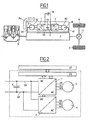
- FIG. figure 1 two electric machines 3, 4 are connected to a mechanical transmission 5 connected to wheels 6, 7 on one side and to a system 8 for storing energy on the other side.
- Two inverters 1, 2 are used to control the machines 3, 4.
- the internal combustion engine is shut down, one of the two machines 3, 4 is used to drive the transmission.
- a common filtering capacitor C is usually mounted on the DC bus between the two inverters 1, 2.
- the inverters 1, 2 cut by opening and closing their switches the DC voltage to generate AC voltages that feed the machines 3, 4. It is called MLI cutting (modulation of the pulse width).
- the high-frequency cutting (a few kHz) generates harmonics in addition to the fundamental useful on the currents of the machines, and in the same way widens the spectrum of the current generated on the DC bus 10.
- the capacitor C filters most of these current harmonics to return as much continuous current as possible to the storage element.
- the aging of the capacitance is sensitive to its heating, and therefore to the effective current flowing through it. It is therefore interesting to control the current to be filtered and its harmonic content.
- a first object of the invention is to optimize the pulse width modulation control of the inverters.
- a second objective of the invention is to minimize the current ripple of the capacitor, as well as the effective current flowing through it.
- a third objective of the invention is to optimize the voltage of the phases of the machines.
- a first object of the invention is a device for controlling a power bypass circuit of a hybrid vehicle, the device comprising first and second inverters whose continuous sides are connected to a DC voltage storage unit, the reciprocating sides of which are intended to be connected to first and second polyphase electrical machines intended to be coupled to the mechanical transmission of the vehicle, the first machine being able to function as a generator and the second machine being able to operate as a motor for the power bypass from the transmission, the inverters further comprising cutting switches for the conversion between continuous sides and reciprocating sides, device comprising a harmonic filtering capacitor on the continuous sides of the inverters and a control unit for the chopper switches, comprising at least one control mode thereof by width modulation pulses of a carrier having an identical frequency for the inverters, characterized in that the first and second machines are able to operate as engine / engine or generator / generator, the control unit comprises means for detecting the operation of the first and second engine / engine or generator / generator machines and first means of control of the switching switches of the second inverter
- a second object of the invention is a method of controlling a power bypass circuit on board a hybrid vehicle, for the implementation of the control device as described above, using first and second inverters whose continuous sides are connected to a DC voltage storage unit, the alternating sides of which are connected to first and second polyphase electrical machines, coupled to the mechanical transmission of the vehicle, the first machine operating as a generator and the second machine operating in a motor for deriving power from the transmission, the inverters further comprising switching switches for converting between the DC and AC sides, a harmonic filtering capability being provided on the continuous sides of the inverters, the cutting being controlled by a control unit having at least one com mode Mande thereof by pulse width modulation of a carrier having an identical frequency for the inverters, characterized in that the first and second machines are operated as engine / engine or generator / generator, the switching switches of the second inverter are controlled in a temporally offset manner with respect to the switching switches of the first inverter in the event of operation of the first and second machines in motor / motor or in
- a third object of the invention is a hybrid vehicle, comprising an internal combustion engine for driving wheels via a mechanical transmission, the mechanical transmission being coupled to first and second electric machines, the first machine being able to operate as a generator and the second machine being able to operate as a motor to form a power bypass circuit from the transmission, characterized in that the first and second electrical machines are connected to an on-board control device as described herein. -above.
- the electrical machines 3, 4 are for example three-phase and each comprise three distinct phases U1, V1, W1, and U2, V2, W2, respectively connected to the alternating side AC of the inverters 1 and 2.
- the machines 3, 4 comprise respectively a movable portion 31, 41, which is mechanically connected to the transmission 5 and which is movable relative to the mechanical part 32, 42 connected to the phases U1, V1, W1, U2, V2, W2.
- the machine 3 When the internal combustion engine 9 operates to mechanically drive the transmission 5 to rotate the wheels 6, 7 through a differential 11, the machine 3 operates as a generator and derives electrical power from the transmission 5 to the alternating AC side of the inverter 1 as represented by the arrow F1, this derived electrical power being converted into direct current on the DC side DC of the inverter 1 to store energy in the storage element 8.
- the other machine 4 then operates as a motor for this power bypass.
- the element 8 of energy storage is for example formed by one or more rechargeable electric batteries, or one or more super-capacitors, as is known.
- the internal combustion engine can also drive the wheels with the machine 3 into the engine and the machine 4 into a generator. The choice of motor / generator or generator / motor modes is chosen by the supervisor.
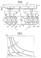
- the inverters 1, 2 respectively comprise switches I1, 12 for cutting the DC current present on their AC DC side on the phases U1, V1, W1 and U2, V2, W2.
- each inverter 1, 2 comprises, for each phase, two switches I1 or 12 in series between the two conductors 10 of the DC bus, the node between the two switches I1 or 12 being connected to the phase U1, V1 or W1, U2, V2 or W2.
- Each switch I1, 12 is for example formed by a transistor type IGBT (insulated gate bipolar transistor) in parallel with which is provided a diode in reverse.
- Each switch I1, I2 has an input E1, E2 to control its opening or closing, this input being formed for the IGBT transistors by their gate.
- the control inputs E1 of the switches I1 of the inverter 1 are connected to a first control circuit 21, while the control inputs E2 of the switches I2 of the inverter 2 are connected to a second control circuit 22.
- the first and second control circuits 21, 22 are connected to a low level control unit 23, comprising a first carrier generation module 24, which is sent to the first circuit 21, and a second carrier generation circuit 25. , which is sent to the second circuit 22.
- the unit 23 comprises one or more computers 26, in particular for the control of the modules 24 and 25.
- the low level control unit 23 is connected to a control unit 27 high level of the vehicle.
- the will of the driver and / or the vehicle control strategy determine the torques and / or speeds applied to the electric machines 3, 4.
- the clipping strategy is selected to solve the problem of reducing the size of the filtering capacitor C, without overly complicating the low-layer control and without impacting the performance of the vehicle.
- Another object is to reduce the current harmonics whose effective current is at the origin of the heating and aging of the C capacity of filtering.
- a "clean" sinusoidal voltage is also desired at the machine terminals.
- the choice of the type of control depends first of all on the speed and the torque demanded from the machines and is selected by the computer 26.
- the vector PWM command is no longer the application of 3 voltages independent of each other as the scalar PWM but as a strategy for driving the rotating vector of a three-phase (or polyphase) system, therefore with pulse synchronization between phases.
- One of the main advantages of this strategy is to be able to provide a fundamental tension greater than that which could be delivered by three juxtaposed independent scalar strategies.
- the full-wave control is preferred when the amplitude of the voltages can not be reached by the other control modes.
- the supply voltage is applied alternately to each pole of the load at the fundamental frequency that is desired. There is thus a maximum amplitude of AC voltage across the terminals of the machines. It is thus possible to reach the areas of high power (torque) at the cost of a current overload (additional losses) due to the low frequency harmonics of the voltage.
- the transitions between the modes are decided according to the electrical losses and their distribution between machine losses and inverter losses.
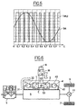
- the figure 4 illustrates different cases of operation.
- the control mode MLI1 scalar is delimited from the point O of zero velocity V and zero CM torque by a first curve C1 torque depending on the speed.
- the second mode MLI2 of vector control is delimited by the curve C1 and a second curve C2 for values of speed V and / or torque CM increasing with respect to the curve C1.
- the third mode MLI3 control over-modulated vector is delimited by the curve C2 and a third curve C3 for values of speed V and / or torque CM increasing with respect to the curve C2.
- the fourth full-wave control mode PO is delimited by the curve C3 and a fourth curve C4 for values of speed V and / or torque CM increasing with respect to the curve C3.
- the curves C1, C2, C3, C4 are decreasing, for example in the manner of hyperbolas.
- the fourth curve C4 is a torque envelope curve of the engine machine.
- the carrier generation module 25 sends to the control circuit 22 of the inverter 2 a carrier shifted by half a period, that is to say in phase opposition, with respect to the carrier of the same frequency sent by the generation module 24 to the control circuit 21 of the inverter 1.
- the carriers sent to the inverters 1 and 2 have the same frequency and are shifted by half a period between them.
- the equilibrium of the phase currents of the two machines is preferred. That is to say that the "high level" control chooses the corresponding torque for the same current on each machine, the sum of the couples being transmitted to the wheel. Typically, this is possible in ZEV driving mode.
- Torques applied to the motor are controlled by the "high level" control.
- the carriers of the two inverters have the same phase and the same frequency.
- the structure may comprise a DC / DC converter between the capacitor C and the storage element 8 so as to have an optimum DC bus voltage for the inverters 1, 2 and 3, 4 d on the one hand, and make this voltage insensitive to the voltage variations of the storage element 8 on the other hand.
- the frequency of the hash harmonics from the DC / DC converter 30 must be of higher frequency than the inverters, which is most of the time the case.
- the low-frequency harmonics of the filtered current will be of a rank greater than 6 times the fundamental frequency of the phase current (twice the number of phases).
- the gap is reduced between the switching harmonics and the harmonics due to the fundamental of the phase current. This may lead to increase the frequency of cutting compared to a three-phase system if this gap is insufficient.
Abstract
Description
L'invention concerne un dispositif de commande d'un circuit de dérivation de puissance d'un véhicule hybride.The invention relates to a device for controlling a power bypass circuit of a hybrid vehicle.
Un domaine d'application de l'invention est les véhicules hybrides routiers.One field of application of the invention is the road hybrid vehicles.
Le document
Ainsi que cela est connu dans les véhicules hybrides à dérivation de puissance et est représenté à la
Une capacité C de filtrage commune est habituellement montée sur le bus 10 de courant continu entre les deux onduleurs 1, 2.A common filtering capacitor C is usually mounted on the DC bus between the two
Les onduleurs 1, 2 découpent par ouverture et fermeture de leurs interrupteurs la tension continue pour générer des tensions alternatives qui alimentent les machines 3, 4. On parle de découpage MLI (modulation de la largeur d'impulsion).The
Le découpage à haute fréquence (quelques kHz) génère des harmoniques en plus du fondamental utile sur les courants des machines, et de la même manière élargit le spectre du courant généré sur le bus continu 10.The high-frequency cutting (a few kHz) generates harmonics in addition to the fundamental useful on the currents of the machines, and in the same way widens the spectrum of the current generated on the
La capacité C filtre l'essentiel de ces harmoniques de courant pour renvoyer un courant le plus continu possible vers l'élément de stockage. Le vieillissement de la capacité est sensible à son échauffement, donc au courant efficace qui la traverse. Il est donc intéressant de contrôler le courant à filtrer et son contenu harmonique.The capacitor C filters most of these current harmonics to return as much continuous current as possible to the storage element. The aging of the capacitance is sensitive to its heating, and therefore to the effective current flowing through it. It is therefore interesting to control the current to be filtered and its harmonic content.
De plus, il existe plusieurs stratégies de découpage possibles pour des onduleurs.In addition, there are several possible cutting strategies for inverters.
Un premier objectif de l'invention est d'optimiser la commande en modulation de largeur d'impulsions des onduleurs.A first object of the invention is to optimize the pulse width modulation control of the inverters.
Un deuxième objectif de l'invention est de minimiser les ondulations de courant de la capacité, ainsi que le courant efficace qui la traverse.A second objective of the invention is to minimize the current ripple of the capacitor, as well as the effective current flowing through it.
Un troisième objectif de l'invention est d'optimiser la tension des phases des machines.A third objective of the invention is to optimize the voltage of the phases of the machines.
Un premier objet de l'invention est un dispositif de commande d'un circuit de dérivation de puissance d'un véhicule hybride,
le dispositif comportant des premier et deuxième onduleurs dont les côtés continus sont reliés à une unité de stockage de tension continue, dont les côtés alternatifs sont destinés à être reliés à des première et deuxième machines électriques polyphasées, destinées à être couplées à la transmission mécanique du véhicule, la première machine étant apte à fonctionner en générateur et la deuxième machine étant apte à fonctionner en moteur pour la dérivation de puissance depuis la transmission, les onduleurs comportant en outre des interrupteurs de découpage pour la conversion entre les côtés continus et les côtés alternatifs, dispositif comportant une capacité de filtrage d'harmoniques sur les côtés continus des onduleurs et une unité de commande des interrupteurs de découpage, comportant au moins un mode de commande de ceux-ci par modulation de largeur d'impulsions d'une porteuse ayant une fréquence identique pour les onduleurs,
caractérisé en ce que
les première et deuxième machines sont aptes à fonctionner en moteur / moteur ou en générateur / générateur, l'unité de commande comporte des moyens de détection du fonctionnement des première et deuxième machines en moteur / moteur ou en générateur / générateur et des premiers moyens de commande des interrupteurs de découpage du deuxième onduleur d'une manière décalée temporellement par rapport aux interrupteurs de découpage du premier onduleur en cas de détection du fonctionnement des première et deuxième machines en moteur / moteur ou en générateur / générateur, et en outre l'unité de commande des onduleurs comporte un moyen de commande de leurs interrupteurs de découpage suivant un mode de modulation vectorielle de largeur d'impulsions.A first object of the invention is a device for controlling a power bypass circuit of a hybrid vehicle,
the device comprising first and second inverters whose continuous sides are connected to a DC voltage storage unit, the reciprocating sides of which are intended to be connected to first and second polyphase electrical machines intended to be coupled to the mechanical transmission of the vehicle, the first machine being able to function as a generator and the second machine being able to operate as a motor for the power bypass from the transmission, the inverters further comprising cutting switches for the conversion between continuous sides and reciprocating sides, device comprising a harmonic filtering capacitor on the continuous sides of the inverters and a control unit for the chopper switches, comprising at least one control mode thereof by width modulation pulses of a carrier having an identical frequency for the inverters,
characterized in that
the first and second machines are able to operate as engine / engine or generator / generator, the control unit comprises means for detecting the operation of the first and second engine / engine or generator / generator machines and first means of control of the switching switches of the second inverter in a temporally offset manner with respect to the switching switches of the first inverter in the event of detection of the operation of the first and second machines in motor / motor or in generator / generator, and furthermore the unit control unit of the inverters comprises means for controlling their switching switches according to a pulse width vector modulation mode.
Suivant d'autres caractéristiques de l'invention :
- Ledit décalage temporel entre le deuxième onduleur et le premier onduleur correspond à une demi - période de la porteuse.
- L'unité de commande des onduleurs comporte un premier mode de commande de leurs interrupteurs de découpage par modulation scalaire de largeur d'impulsions, un deuxième mode de commande de leurs interrupteurs de découpage par modulation vectorielle de largeur d'impulsions, un troisième mode de commande de leurs interrupteurs de découpage par modulation de largeur d'impulsions sur - modulée et un quatrième mode de commande de leurs interrupteurs de découpage pleine onde.
- L'unité de commande comporte un moyen de sélection d'un mode pour appliquer aux onduleurs le premier, deuxième, troisième ou quatrième mode pour des valeurs associées de vitesses et de couples de machines situées respectivement dans des premier, deuxième, troisième et quatrième domaines adjacents de valeurs croissantes.
- L'unité de commande comporte, en plus des premiers moyens de commande, des moyens de détection du fonctionnement des première et deuxième machines en moteur/générateur ou en générateur/moteur et des moyens de commande des interrupteurs de découpage du deuxième onduleur avec la même phase temporelle que les interrupteurs de découpage du premier onduleur en cas de détection du fonctionnement des première et deuxième machine en moteur/générateur ou en générateur/moteur.
- Un convertisseur continu - continu est intercalé entre la capacité et l'unité de stockage d'énergie.
- Said time difference between the second inverter and the first inverter corresponds to half a period of the carrier.
- The control unit of the inverters comprises a first mode of controlling their pulse width modulated pulse switching switches, a second mode of controlling their pulse width vector modulation switching switches, a third mode of control of their pulse modulated pulse width switching switches and a fourth control mode of their full wave cutters.
- The control unit includes mode selection means for applying to the inverters the first, second, third or fourth mode for associated values of speeds and machine pairs located respectively in first, second, third and fourth adjacent domains of increasing values.
- The control unit comprises, in addition to the first control means, means for detecting the operation of the first and second machines in motor / generator or generator / motor and control means of the switching switches of the second inverter with the same temporal phase as the switching switches of the first inverter in case of detection of the operation of the first and second engine machine / generator or generator / engine.
- A DC / DC converter is interposed between the capacitor and the energy storage unit.
Un deuxième objet de l'invention est un procédé de commande d'un circuit de dérivation de puissance à bord d'un véhicule hybride, pour la mise en oeuvre du dispositif de commande tel que décrit ci-dessus, utilisant des premier et deuxième onduleurs dont les côtés continus sont reliés à une unité de stockage de tension continue, dont les côtés alternatifs sont reliés à des première et deuxième machines électriques polyphasées, couplées à la transmission mécanique du véhicule, la première machine fonctionnant en générateur et la deuxième machine fonctionnant en moteur pour la dérivation de puissance depuis la transmission, les onduleurs comportant en outre des interrupteurs de découpage pour la conversion entre les côtés continus et les côtés alternatifs, une capacité de filtrage d'harmoniques étant prévue sur les côtés continus des onduleurs, les interrupteurs de découpage étant commandés par une unité de commande ayant au moins un mode de commande de ceux-ci par modulation de largeur d'impulsions d'une porteuse ayant une fréquence identique pour les onduleurs,
caractérisé en ce que
on fait fonctionner les première et deuxième machines en moteur / moteur ou en générateur / générateur,
on commande les interrupteurs de découpage du deuxième onduleur d'une manière décalée temporellement par rapport aux interrupteurs de découpage du premier onduleur en cas de fonctionnement des première et deuxième machines en moteur / moteur ou en générateur / générateur.A second object of the invention is a method of controlling a power bypass circuit on board a hybrid vehicle, for the implementation of the control device as described above, using first and second inverters whose continuous sides are connected to a DC voltage storage unit, the alternating sides of which are connected to first and second polyphase electrical machines, coupled to the mechanical transmission of the vehicle, the first machine operating as a generator and the second machine operating in a motor for deriving power from the transmission, the inverters further comprising switching switches for converting between the DC and AC sides, a harmonic filtering capability being provided on the continuous sides of the inverters, the cutting being controlled by a control unit having at least one com mode Mande thereof by pulse width modulation of a carrier having an identical frequency for the inverters,
characterized in that
the first and second machines are operated as engine / engine or generator / generator,
the switching switches of the second inverter are controlled in a temporally offset manner with respect to the switching switches of the first inverter in the event of operation of the first and second machines in motor / motor or in generator / generator.
Suivant d'autres caractéristiques de l'invention :
- Le décalage temporel entre le deuxième onduleur et le premier onduleur en cas de fonctionnement des première et deuxième machines en moteur / moteur ou en générateur / générateur correspond à une demi - période de la porteuse.
- On commande les interrupteurs de découpage des onduleurs selon un premier mode de commande par modulation scalaire de largeur d'impulsions, selon un deuxième mode de commande par modulation vectorielle de largeur d'impulsions, selon un troisième mode de commande par modulation de largeur d'impulsions sur - modulée et selon un quatrième mode de commande pleine onde pour des valeurs associées de vitesses et de couples des machines situées respectivement dans des premier, deuxième, troisième et quatrième domaines adjacents de valeurs croissantes.
- The time difference between the second inverter and the first inverter in the case of operation of the first and second engine / engine or generator / generator machines corresponds to half a period of the carrier.
- The switching switches of the inverters are controlled according to a first control mode by scalar modulation of pulse width, according to a second control mode by pulse width vector modulation, according to a third modulation mode of width modulation. over modulated pulses and according to a fourth full wave control mode for associated velocity and torque values of the machines located respectively in first, second, third and fourth adjacent domains of increasing values.
Un troisième objet de l'invention est un véhicule hybride, comportant un moteur à combustion interne pour l'entraînement de roues par l'intermédiaire d'une transmission mécanique, la transmission mécanique étant couplée à des première et deuxième machine électriques, la première machine étant apte à fonctionner en générateur et la deuxième machine étant apte à fonctionner en moteur pour former un circuit de dérivation de puissance depuis la transmission, caractérisé en ce que les première et deuxième machines électriques sont reliées à un dispositif embarqué de commande tel que décrit ci-dessus.A third object of the invention is a hybrid vehicle, comprising an internal combustion engine for driving wheels via a mechanical transmission, the mechanical transmission being coupled to first and second electric machines, the first machine being able to operate as a generator and the second machine being able to operate as a motor to form a power bypass circuit from the transmission, characterized in that the first and second electrical machines are connected to an on-board control device as described herein. -above.
L'invention sera mieux comprise à la lecture de la description qui va suivre, donnée uniquement à titre d'exemple non limitatif en référence aux dessins annexés, sur lesquels :
- la
figure 1 est un synoptique de la transmission d'un véhicule hybride, - la
figure 2 est un synoptique de la partie électrotechnique reliée à la transmission mécanique selon lafigure 1 , - la
figure 3 est un synoptique détaillé des deux onduleurs de la partie électrotechnique de lafigure 2 , - la
figure 4 est un diagramme représentant en abscisse la vitesse de rotation de la machine électrique et en ordonnée le couple de la machine électrique et des courbes délimitant les choix de découpage des tensions par les onduleurs en fonction des zones de fonctionnement de la machine, - la
figure 5 représente un exemple du signal de courant obtenu par modulation scalaire d'un sinus en fonction du temps en abscisse, - la
figure 6 est un synoptique de la transmission selon lafigure 1 avec convertisseur continu -/continu.
- the
figure 1 is a synoptic of the transmission of a hybrid vehicle, - the
figure 2 is a synoptic of the electrotechnical part connected to the mechanical transmission according to thefigure 1 , - the
figure 3 is a detailed synoptic of the two inverters of the electrotechnical part of thefigure 2 , - the
figure 4 is a diagram representing in abscissa the speed of rotation of the electric machine and ordinate the torque of the electric machine and curves delimiting the choice of voltage switching by the inverters according to the operating zones of the machine, - the
figure 5 represents an example of the current signal obtained by scalar modulation of a sinus as a function of time on the abscissa, - the
figure 6 is a synoptic of the transmission according to thefigure 1 with continuous - / continuous converter.
Aux figures, les machines électriques 3, 4 sont par exemple triphasées et comportent chacune trois phases distinctes U1, V1, W1, et U2, V2, W2, reliées respectivement au côté alternatif AC des onduleurs 1 et 2. Les machines 3, 4 comportent respectivement une partie mobile 31, 41, qui est reliée mécaniquement à la transmission 5 et qui est mobile par rapport à la partie mécanique 32, 42 reliée aux phases U1, V1, W1, U2, V2, W2.In the figures, the
Lorsque le moteur 9 à combustion interne fonctionne pour entraîner mécaniquement la transmission 5 pour entraîner en rotation les roues 6, 7 par l'intermédiaire d'un différentiel 11, la machine 3 fonctionne en générateur et dérive de la puissance électrique depuis la transmission 5 vers le côté alternatif AC de l'onduleur 1 ainsi que représenté par la flèche F1, cette puissance électrique dérivée étant transformée en courant continu sur le côté continu DC de l'onduleur 1 pour stocker de l'énergie dans l'élément 8 de stockage. L'autre machine 4 fonctionne alors en moteur pour cette dérivation de puissance. L'élément 8 de stockage d'énergie est par exemple formé par une ou plusieurs batteries électriques rechargeables, ou une ou plusieurs super-capacités, ainsi que cela est connu. Le moteur à combustion interne peut également entraîner les roues avec la machine 3 en moteur et la machine 4 en générateur. Le choix des modes moteur / générateur ou générateur / moteur est choisi par le superviseur.When the
Les onduleurs 1, 2 comportent respectivement des interrupteurs I1, 12 pour découper le courant continu présent sur leur côté DC en courant alternatif sur les phases U1, V1, W1 et U2, V2, W2. Par exemple, à la
La volonté du conducteur et/ou la stratégie de contrôle du véhicule déterminent les couples et/ou les vitesses appliquées aux machines électriques 3, 4.The will of the driver and / or the vehicle control strategy determine the torques and / or speeds applied to the
Indépendamment de cette commande « couche haute » issue d'un superviseur 27, il est possible de contrôler les signaux « couche basse » des onduleurs ; notamment la stratégie du découpage en tension des machines 3, 4. La commande « couche basse » est intégrée dans le ou les calculateurs 26. Ce ou ces calculateurs 26 pilotent les circuits de commande 21, 22 qui transmettent les ordres de commutation ON/OFF à l'interrupteur 11, 12.Independently of this "high layer" command from a
Il existe plusieurs fonctionnements des machines électriques, choisis par le contrôle « haut niveau » du véhicule. Les deux machines peuvent fonctionner en :
- ■ moteur/moteur,
- ■ générateur/moteur,
- ■ moteur/générateur,
- ■ générateur / générateur.
- ■ motor / motor,
- ■ generator / motor,
- ■ motor / generator,
- ■ generator / generator.
La tension de phase des machines est découpée, suivant des premier, deuxième, troisième et quatrième modes de commande imposés par le calculateur 26 de l'unité 23 aux circuits 21, 22, respectivement en :
- ■ MLI scalaire, désignée aux figures par MLI1,
- ■ MLI vectorielle, désignée aux figures par MLI2,
- ■ MLI sur-modulé, désignée aux figures par MLI3,
- ■ Pleine onde, désignée aux figures par PO.
- ■ Scalar MLI, designated in the figures by MLI1,
- ■ MLI vector, designated in the figures by MLI2,
- ■ Over-modulated PWM, designated in the figures by MLI3,
- ■ Full wave, designated in the figures by PO.
La stratégie de découpage est sélectionnée pour résoudre le problème consistant à réduire le dimensionnement de la capacité C de filtrage, sans pour autant trop complexifier la commande couche basse et sans impacter les performances du véhicule.The clipping strategy is selected to solve the problem of reducing the size of the filtering capacitor C, without overly complicating the low-layer control and without impacting the performance of the vehicle.
Un autre but est de réduire les harmoniques de courant dont le courant efficace est à l'origine de l'échauffement et du vieillissement de la capacité C de filtrage. Une tension sinusoïdale "propre" est également souhaitée aux bornes des machines.Another object is to reduce the current harmonics whose effective current is at the origin of the heating and aging of the C capacity of filtering. A "clean" sinusoidal voltage is also desired at the machine terminals.
Par conséquent, on se dispense de devoir automatiquement surdimensionner la capacité C pour résoudre ces problèmes.Therefore, one avoids having to automatically oversize the capacity C to solve these problems.
On cherche à réduire au maximum le courant filtré par la capacité, suivant les cas de fonctionnement du véhicule et des machines électriques.It seeks to minimize the filtered current by capacity, depending on the operation of the vehicle and the electrical machines.
En même temps, on cherche à appliquer la tension la plus propre (c'est-à-dire dont les premiers harmoniques, en dehors du fondamental, sont à la fréquence du découpage ; il n'y a pas d'harmoniques impairs 3, 5, 7, et suivants, les premiers rangs proviennent du découpage) aux machines suivant les consignes de couples et de vitesse.At the same time, we try to apply the cleanest voltage (that is to say, whose first harmonics, outside the fundamental, are at the frequency of the division, there are no
Le choix du type de commande dépend en premier lieu de la vitesse et du couple demandé aux machines et est sélectionné par le calculateur 26.The choice of the type of control depends first of all on the speed and the torque demanded from the machines and is selected by the
On privilégie la commande MLI scalaire lorsqu'une machine est alimentée par une tension de faible amplitude. Dans l'état de l'art, une méthode simple pour générer un tel signal MLI est de faire une comparaison entre une porteuse triangulaire (à la fréquence du découpage MLI) et le signal de consigne (modulante). Dans les faits, la largeur d'impulsions est de plus en plus issue du résultat d'un calculateur numérique au détriment d'une comparaison analogique. La
L'utilisation de cette commande permet d'appliquer de faibles tensions (voire nulle) aux machines. Elle est donc parfaitement adaptée aux zones de basses vitesses.The use of this command makes it possible to apply low voltages (or even zero) to the machines. It is therefore perfectly adapted to low speed areas.
Dans la majorité des cas d'utilisation, on privilégie une commande MLI vectorielle.In the majority of the cases of use, one privileges a control MLI vector.
La commande MLI vectorielle est non plus l'application de 3 tensions indépendantes l'une de l'autre comme la MLI scalaire mais comme une stratégie pour piloter le vecteur tournant d'un système triphasé (ou polyphasé), donc avec une synchronisation des impulsions entre phases. L'un des principaux avantages de cette stratégie est de pouvoir fournir une tension fondamentale supérieure à celle que pourraient délivrer trois stratégies scalaires indépendantes juxtaposées.The vector PWM command is no longer the application of 3 voltages independent of each other as the scalar PWM but as a strategy for driving the rotating vector of a three-phase (or polyphase) system, therefore with pulse synchronization between phases. One of the main advantages of this strategy is to be able to provide a fundamental tension greater than that which could be delivered by three juxtaposed independent scalar strategies.
Lorsque l'on atteint l'amplitude maximale de tension sinusoïdale que l'on peut générer en MLI vectorielle, on parle alors de MLI sur-modulé. Dans ce cas, sont ajoutés des harmoniques multiples de la fréquence fondamentale dans le signal de façon à augmenter l'amplitude de ce dernier.When we reach the maximum amplitude of sinusoidal voltage that can be generated in vector PWM, we speak of over-modulated PWM. In this case, multiple harmonics of the fundamental frequency in the signal are added so as to increase the amplitude of the latter.
On privilégie la commande pleine onde lorsque l'amplitude des tensions ne peut être atteinte par les autres modes de commande. La tension d'alimentation est appliquée alternativement sur chaque pôle de la charge à la fréquence fondamentale que l'on souhaite obtenir. On a ainsi un maximum d'amplitude de tension alternative aux bornes des machines. On parvient ainsi à atteindre les zones de forte puissance (couple) au prix d'une surcharge en courant (pertes supplémentaires) due aux harmoniques basse fréquence de la tension.The full-wave control is preferred when the amplitude of the voltages can not be reached by the other control modes. The supply voltage is applied alternately to each pole of the load at the fundamental frequency that is desired. There is thus a maximum amplitude of AC voltage across the terminals of the machines. It is thus possible to reach the areas of high power (torque) at the cost of a current overload (additional losses) due to the low frequency harmonics of the voltage.
Les transitions entre les modes sont décidées en fonction des pertes électriques et leur répartition entre pertes machines et pertes onduleur. La
A la
Le choix du type de commande dépend également des cas d'utilisation des deux machines 3, 4.The choice of the type of control also depends on the use of the two
Ces modes sont exploités en ZEV (roulage exclusivement électrique, correspondant à l'arrêt du moteur 9 à combustion interne).These modes are operated in ZEV (exclusively electric driving, corresponding to the stopping of the internal combustion engine 9).
Si les deux machines sont commandées en MLI, on déphasera le découpage d'une machine par rapport à l'autre. Ce décalage est par exemple d'une demi-période de porteuse. Les deux porteuses ont la même fréquence. Dans le mode de réalisation de la
Le fait que les machines 3, 4 fonctionnent chacune en moteur ou chacune en générateur est détecté par tout moyen MD approprié de détection, cet état ED de détection de fonctionnement en moteur - moteur ou générateur - générateur des machines 3, 4 étant envoyé à l'unité 23 de commande pour décaler les porteuses des modules 24 et 25.The fact that the
Dans un exemple où les deux machines 3, 4 en mode moteur ont été commandées en modulation de largeur d'impulsion vectorielle, lorsque la somme des courants à filtrer des deux onduleurs a été de 76,5 Ampères efficaces (c'est-à-dire RMS) pour des porteuses non décalées, cette somme des courants à filtrer des deux onduleurs était de 46,8 Ampères efficaces avec la commande en modulation de largeur d'impulsion vectorielle pour des porteuses décalées d'une demi-période, soit une diminution de 39% du courant efficace à filtrer par la capacité C.In an example where the two
Dans un mode de réalisation, on privilégie l'équilibre des courants de phase des deux machines. C'est-à-dire que le contrôle « haut niveau » choisit le couple correspondant pour un même courant sur chaque machine, la somme des couples étant transmise à la roue. Typiquement, cela est possible en mode de roulage ZEV.In one embodiment, the equilibrium of the phase currents of the two machines is preferred. That is to say that the "high level" control chooses the corresponding torque for the same current on each machine, the sum of the couples being transmitted to the wheel. Typically, this is possible in ZEV driving mode.
Il s'agit d'un mode de fonctionnement habituel du véhicule hybride. Les couples appliqués au moteur sont pilotés par le contrôle «haut niveau».This is a common mode of operation of the hybrid vehicle. Torques applied to the motor are controlled by the "high level" control.
Comme les courants sont naturellement de sens opposés, le courant à filtrer sur le bus continu 10 se réduit naturellement.Since the currents naturally have opposite directions, the current to be filtered on the
Si les deux machines sont commandées en MLI, on préférera que les porteuses des deux onduleurs aient la même phase et la même fréquence.If the two machines are controlled in MLI, it will be preferred that the carriers of the two inverters have the same phase and the same frequency.
Dans le mode de réalisation de la
Dans ce cas, la fréquence des harmoniques de hachage issus du convertisseur continu / continu 30 doivent être de fréquence supérieure à ceux des onduleurs, ce qui est la plupart du temps le cas.In this case, the frequency of the hash harmonics from the DC /
Bien que peu utilisée, une variante avec des moteurs de plus de trois phases peu être envisagée. La conséquence principale est que les harmoniques basse fréquence du courant à filtré seront d'un rang supérieur à 6 fois la fréquence fondamentale du courant de phase (2 fois le nombre de phases).Although little used, a variant with motors of more than three phases can be considered. The main consequence is that the low-frequency harmonics of the filtered current will be of a rank greater than 6 times the fundamental frequency of the phase current (twice the number of phases).
La principale conséquence est que l'écart se réduit entre les harmoniques de découpage et les harmoniques dues aux fondamental du courant de phase. Ceci peu amener à augmenter la fréquence du découpage par rapport à un système triphasé si cet écart est insuffisant.The main consequence is that the gap is reduced between the switching harmonics and the harmonics due to the fundamental of the phase current. This may lead to increase the frequency of cutting compared to a three-phase system if this gap is insufficient.
Ainsi, en entrée des onduleurs 1, 2 (côté continu), on minimise les ondulations de courant de la capacité C. En sortie (côté alternatif) des onduleurs 1, 2, on minimise l'erreur en consigne et fondamental des tensions aux bornes des machines 3, 4, pour avoir ainsi des tensions sinus propres. Bien entendu, on peut soit seulement minimiser les ondulations de courant, soit seulement avoir une tension de sortie propre.Thus, at the input of the
Claims (10)
- Device for controlling a power shunt circuit of a hybrid vehicle,
the device comprising first and second inverters (1, 2) the DC sides of which are connected to a DC-Voltage storage unit (8), the AC sides of which are designed to be connected to first and second polyphase electric machines (3, 4), designed to be coupled to the mechanical drive (5) of the vehicle, the first machine (3) being capable of operating as a generator and the second machine (4) being capable of operating as a motor for the shunting of power from the drive (5), the inverters (1, 2) also comprising chopping switches for the conversion between the DC sides and the AC sides, the device comprising a capacitor (C) for filtering harmonics on the DC sides of the inverters (1, 2) and a unit (23) for controlling the chopping switches, comprising at least one mode for controlling the latter by pulse-width modulation of a carrier having an identical frequency for the inverters (1, 2), the unit (23) for controlling the inverters also comprising a means (26) for controlling their chopping switches (I1, 12) according to a pulse-width vectorial modulation mode (MLI2),
characterized in that
the first and second machines (3, 4) are capable of operating as motor/motor or as generator/generator, the control unit (23) comprises means (MD) for detecting the operation of the first and second machines (3, 4) as motor/motor or as generator/ generator and first means (24, 25) for controlling the chopping switches (I2) of the second inverter (2) in a time-shifted manner relative to the chopping switches (I1) of the first inverter (1) in the event of detection of the operation of the first and second machines (3, 4) as motor/motor or as generator/generator, and also the unit (23) for controlling the inverters comprises- a first mode (MLI1) for controlling their chopping switches (I1, 2) by pulse-width scalar modulation,- a second mode (MLI2) for controlling their chopping switches (I1, I2) by pulse-width vectorial modulation,- a third mode (MLI3) for controlling their chopping switches (I1, I2) by overmodulated pulse-width modulation and- a fourth, full wave, mode (PO) for controlling their chopping switches (I1, I2). - Control device according to Claim 1, characterized in that said time shift between the second inverter (2) and the first inverter (1) comprises a half-period of the carrier.
- Control device according to either of the preceding claims, characterized in that the control unit (23) comprises a mode-selection means (26) for applying to the inverters (1, 2) the first, second, third or fourth mode for associated speed and torque values of machines (3, 4) situated respectively in first, second, third and fourth adjacent fields of increasing values.
- Control device according to Claim 3, characterized in that the first scalar control mode (MLI1) is delimited from the point (O) of zero speed (V) and of zero torque (CM) by a first torque curve (C1) as a function of the speed, the second vectorial control mode (MLI2) is delimited by the first curve (C1) and a second curve (C2) for speed values (V) and/or torque values (CM) that are increasing relative to the first curve (C1), the third vectorial overmodulated control mode (MLI3) is delimited by the second curve (C2) and a third curve (C3) for speed values (V) and/or torque values (CM) that are increasing relative to the second curve (C2), the fourth full wave control mode (PO) is delimited by the third curve (C3) and a fourth curve (C4) for speed values (V) and/or torque values (CM) that are increasing relative to the third curve (C3), the first, second, third and fourth curves (C1, C2, C3, C4) being decreasing, the fourth curve (C4) being an envelope curve of torque of one of the machines operating as motor.
- Control device according to any one of the preceding claims, characterized in that the control unit (23) comprises, in addition to the first control means (24, 25), means for detecting the operation of the first and second machines (3, 4) as motor/generator or as generator/motor and means (23) for controlling the chopping switches (I2) of the second inverter (2) with the same time phase as the chopping switches (I1) of the first inverter (1) in the event of detection of the operation of the first and second machine (3, 4) as motor/generator or as generator/motor.
- Control device according to any one of the preceding claims, characterized in that a DC-DC converter (30) is inserted between the capacitor (C) and the power storage unit (8).
- Method for controlling a power shunt circuit onboard a hybrid vehicle, for applying the control device according to any one of the preceding claims, using first and second inverters (1, 2) the DC sides of which are connected to a DC-voltage storage unit (8), the AC sides of which are connected to first and second polyphase electric machines (3, 4), coupled to the mechanical drive (5) of the vehicle, the first machine (3) operating as a generator and the second machine (4) operating as a motor for the shunting of power from the drive (5), the inverters (1, 2) also comprising chopping switches for the conversion between the DC sides and the AC sides, a capacitor (C) for filtering harmonics being provided on the DC sides of the inverters (1, 2), the chopping switches being controlled by a control unit (23) having at least one mode for controlling the latter by pulse-width modulation of a carrier having an identical frequency for the inverters (1, 2),
characterized in that
the first and second machines (3, 4) are made to operate as motor/motor or as generator/generator,
the chopping switches (I2) of the second inverter (2) are controlled in a time-shifted manner relative to the chopping switches (I1) of the first inverter (1) in the event of operation of the first and second machines (3, 4) as motor/motor or as generator/generator,
the chopping switches (I1, I2) of the inverters (1, 2) are controlled according to a first pulse-width scalar modulation control mode (MLI1), according to a second pulse-width vectorial modulation control mode (MLI2), according to a third overmodulated pulse-width modulation control mode (MLI3), and according to a fourth, full wave, control mode (PO) for associated speed and torque values of the machines (3, 4) situated respectively in first, second, third and fourth adjacent fields of increasing values. - Control method according to Claim 7, characterized in that the time shift between the second inverter (2) and the first inverter (1) in the event of operation of the first and second machines (3, 4) as motor/motor or as generator/generator corresponds to a half-period of the carrier.
- Control method according to either one of Claims 7 and 8, characterized in that the first scalar control mode (MLI1) is delimited from the point (O) of zero speed (V) and of zero torque (CM) by a first torque curve (C1) as a function of the speed, the second vectorial control mode (MLI2) is delimited by the first curve (C1) and a second curve (C2) for speed values (V) and/or torque values (CM) that are increasing relative to the first curve (C1), the third vectorial overmodulated control mode (MLI3) is delimited by the second curve (C2) and a third curve (C3) for speed values (V) and/or torque values (CM) that are increasing relative to the second curve (C2), the fourth full wave control mode (PO) is delimited by the third curve (C3) and a fourth curve (C4) for speed values (V) and/or torque values (CM) that are increasing relative to the third curve (C3), the first, second, third and fourth curves (C1, C2, C3, C4) being decreasing, the fourth curve (C4) being an envelope curve of torque of one of the machines operating as motor.
- Hybrid vehicle, comprising an internal combustion engine (9) for driving wheels (6, 7) via a mechanical drive (5), the mechanical drive (5) being coupled to first and second electric machines (3, 4), the first machine (3) being capable of operating as a generator and the second machine (4) being capable of operating as a motor in order to form a power shunt circuit from the drive (5), characterized in that the first and second electric machines (3, 4) are connected to an onboard control device according to any one of Claims 1 to 6.
Applications Claiming Priority (2)
| Application Number | Priority Date | Filing Date | Title |
|---|---|---|---|
| FR0703182A FR2915722B1 (en) | 2007-05-03 | 2007-05-03 | "DEVICE AND METHOD FOR CONTROLLING A POWER DERIVATION CIRCUIT, HYBRID VEHICLE HAVING THE SAME" |
| PCT/FR2008/050767 WO2008148977A2 (en) | 2007-05-03 | 2008-04-28 | Device and method for controlling a power shunt circuit, hybrid vehicle having same |
Publications (2)
| Publication Number | Publication Date |
|---|---|
| EP2142397A2 EP2142397A2 (en) | 2010-01-13 |
| EP2142397B1 true EP2142397B1 (en) | 2012-03-14 |
Family
ID=38855023
Family Applications (1)
| Application Number | Title | Priority Date | Filing Date |
|---|---|---|---|
| EP08805721A Active EP2142397B1 (en) | 2007-05-03 | 2008-04-28 | Device and method for controlling a power shunt circuit, hybrid vehicle having same |
Country Status (7)
| Country | Link |
|---|---|
| US (1) | US8310084B2 (en) |
| EP (1) | EP2142397B1 (en) |
| JP (1) | JP5528327B2 (en) |
| CN (1) | CN101678778B (en) |
| AT (1) | ATE549200T1 (en) |
| FR (1) | FR2915722B1 (en) |
| WO (1) | WO2008148977A2 (en) |
Families Citing this family (13)
| Publication number | Priority date | Publication date | Assignee | Title |
|---|---|---|---|---|
| FR2915722B1 (en) * | 2007-05-03 | 2009-08-28 | Renault Sas | "DEVICE AND METHOD FOR CONTROLLING A POWER DERIVATION CIRCUIT, HYBRID VEHICLE HAVING THE SAME" |
| JP4347377B2 (en) * | 2007-11-06 | 2009-10-21 | トヨタ自動車株式会社 | Hybrid vehicle and control method thereof |
| JP5297953B2 (en) * | 2009-09-08 | 2013-09-25 | トヨタ自動車株式会社 | Electric motor drive system for electric vehicle |
| DE102010004712A1 (en) * | 2010-01-11 | 2011-07-14 | Dr. Ing. h.c. F. Porsche Aktiengesellschaft, 70435 | Hybrid drive of a hybrid vehicle |
| JP5984336B2 (en) | 2011-02-25 | 2016-09-06 | Ntn株式会社 | Driving device for in-wheel motor vehicle |
| US9014300B2 (en) * | 2013-09-12 | 2015-04-21 | Qualcomm Incorporated | Switched-mode high-linearity transmitter using pulse width modulation |
| US10476267B2 (en) * | 2015-11-10 | 2019-11-12 | Caterpillar Inc. | Smart load bank and excitation control |
| CN105471239A (en) * | 2015-12-31 | 2016-04-06 | 清华大学苏州汽车研究院(吴江) | Method for eliminating ripple waves in bus capacitor of dual motor-inverter system |
| US20180145609A1 (en) * | 2016-11-23 | 2018-05-24 | General Electric Company | Hybrid switch for inverter of computed tomography system |
| CN106671970A (en) * | 2016-12-23 | 2017-05-17 | 广东戈兰玛汽车系统有限公司 | Electric vehicle power assembly central controller |
| FR3062003B1 (en) * | 2017-01-16 | 2020-01-03 | Valeo Equipements Electriques Moteur | CONTROL SYSTEM FOR A ROTATING ELECTRIC MACHINE |
| DE102019203776A1 (en) * | 2019-03-20 | 2020-09-24 | Zf Friedrichshafen Ag | Device and method for controlling at least two inverters |
| DE102019204398A1 (en) * | 2019-03-28 | 2020-10-01 | Zf Friedrichshafen Ag | Device and method for controlling at least two inverters |
Family Cites Families (19)
| Publication number | Priority date | Publication date | Assignee | Title |
|---|---|---|---|---|
| JPH0815394B2 (en) * | 1983-10-31 | 1996-02-14 | 株式会社安川電機 | Connection / control method of multiple coupling inverter device |
| JPH0479770A (en) * | 1990-07-20 | 1992-03-13 | Toshiba Corp | 3-phase pwm signal generating circuit of inverter |
| US5142468A (en) * | 1991-05-16 | 1992-08-25 | General Atomics | Power conditioning system for use with two PWM inverters and at least one other load |
| JP2884942B2 (en) * | 1992-09-17 | 1999-04-19 | 株式会社日立製作所 | Electric car control device |
| JPH07322636A (en) * | 1994-05-27 | 1995-12-08 | Mitsubishi Electric Corp | Pulse width modulation method of three-phase inverter |
| JP2000078850A (en) * | 1998-08-31 | 2000-03-14 | Aisin Aw Co Ltd | Inverter device and control method therefor |
| US6337803B2 (en) * | 1999-06-24 | 2002-01-08 | Nissan Motor Co., Ltd. | Power module |
| JP3555567B2 (en) * | 2000-09-04 | 2004-08-18 | 日産自動車株式会社 | Control device for rotating electric machine |
| JP4023171B2 (en) * | 2002-02-05 | 2007-12-19 | トヨタ自動車株式会社 | LOAD DRIVE DEVICE, CHARGE CONTROL METHOD FOR POWER STORAGE DEVICE IN LOAD DRIVE DEVICE, AND COMPUTER-READABLE RECORDING MEDIUM CONTAINING PROGRAM FOR CAUSING COMPUTER TO EXECUTE CHARGE CONTROL |
| JP3582523B2 (en) * | 2002-09-17 | 2004-10-27 | トヨタ自動車株式会社 | Electric load device, abnormality processing method, and computer-readable recording medium recording a program for causing a computer to execute electric load abnormality processing |
| JP2004282826A (en) * | 2003-03-13 | 2004-10-07 | Honda Motor Co Ltd | Engine driven generator |
| US7023171B2 (en) * | 2003-11-12 | 2006-04-04 | Ut-Battelle Llc | Integrated inverter for driving multiple electric machines |
| US7425806B2 (en) * | 2004-04-12 | 2008-09-16 | York International Corporation | System and method for controlling a variable speed drive |
| JP4706324B2 (en) * | 2005-05-10 | 2011-06-22 | トヨタ自動車株式会社 | Control device for motor drive system |
| JP4281725B2 (en) * | 2005-09-01 | 2009-06-17 | トヨタ自動車株式会社 | Hybrid car |
| JP4690151B2 (en) * | 2005-09-07 | 2011-06-01 | 三菱電機株式会社 | Power converter |
| JP4261537B2 (en) * | 2005-09-30 | 2009-04-30 | ジヤトコ株式会社 | Electric motor control device |
| CN2872731Y (en) * | 2006-02-10 | 2007-02-21 | 重庆长安汽车股份有限公司 | DC converter circuit for mixed-power automobile |
| FR2915722B1 (en) * | 2007-05-03 | 2009-08-28 | Renault Sas | "DEVICE AND METHOD FOR CONTROLLING A POWER DERIVATION CIRCUIT, HYBRID VEHICLE HAVING THE SAME" |
-
2007
- 2007-05-03 FR FR0703182A patent/FR2915722B1/en not_active Expired - Fee Related
-
2008
- 2008-04-28 CN CN2008800186906A patent/CN101678778B/en active Active
- 2008-04-28 EP EP08805721A patent/EP2142397B1/en active Active
- 2008-04-28 AT AT08805721T patent/ATE549200T1/en active
- 2008-04-28 WO PCT/FR2008/050767 patent/WO2008148977A2/en active Application Filing
- 2008-04-28 JP JP2010506976A patent/JP5528327B2/en active Active
- 2008-04-28 US US12/598,641 patent/US8310084B2/en active Active
Also Published As
| Publication number | Publication date |
|---|---|
| US20100156172A1 (en) | 2010-06-24 |
| WO2008148977A3 (en) | 2009-02-05 |
| JP2010527306A (en) | 2010-08-12 |
| FR2915722B1 (en) | 2009-08-28 |
| US8310084B2 (en) | 2012-11-13 |
| EP2142397A2 (en) | 2010-01-13 |
| WO2008148977A2 (en) | 2008-12-11 |
| JP5528327B2 (en) | 2014-06-25 |
| CN101678778B (en) | 2012-09-19 |
| FR2915722A1 (en) | 2008-11-07 |
| CN101678778A (en) | 2010-03-24 |
| ATE549200T1 (en) | 2012-03-15 |
Similar Documents
| Publication | Publication Date | Title |
|---|---|---|
| EP2142397B1 (en) | Device and method for controlling a power shunt circuit, hybrid vehicle having same | |
| EP1632019B1 (en) | Pulse width modulation control circuit for multi-mode electrical machine and multimode electrical machine provided with such a control circuit | |
| EP2442436B1 (en) | Control method and system for reducing the common-mode current in a power converter | |
| EP2408087B1 (en) | Method for controlling switching arm switches, in particular for loading accumulation resources, and the corresponding loading device | |
| EP2982036A1 (en) | Device for controlling a polyphase inverter | |
| FR2896106A1 (en) | Salient pole motor-generator controlling apparatus for motor vehicle, has excitation unit exciting stator by voltages at level of starting angles controlled to change continuously according to converter`s voltage and motor-generator`s speed | |
| EP3295550B1 (en) | Ac output multilevel middle power converter device | |
| EP2146856B1 (en) | Electric energy exchange system, in particular for a hybrid vehicle | |
| FR2961975A1 (en) | ELECTRICAL DEVICE COMPRISING AN ALTERNATING CURRENT ELECTRIC MOTOR AND A CONTROL INVERTER AND A METHOD FOR MEASURING THE ELECTROMOTIVE FORCE OF THIS DEVICE | |
| EP3657664B1 (en) | Method for controlling a three-phase electrical machine | |
| EP2823562B1 (en) | Method for controlling a power bridge, and corresponding control device, power bridge and rotary electric machine | |
| EP3369166B1 (en) | System for converting a dc electric power into an ac electric power with an energy recovery module | |
| EP3298687B1 (en) | Method and device for controlling a rotating electrical machine by pwm signals, and corresponding electrical machine of a motor vehicle | |
| EP3476034B1 (en) | System and method for converting dc power into three-phase ac power, the system comprising filtering means | |
| FR3043285B1 (en) | METHOD AND DEVICE FOR CONTROLLING A ROTARY ELECTRIC MACHINE OF A MOTOR VEHICLE, AND CORRESPONDING MACHINE | |
| EP2815501B1 (en) | Module for the regeneration of electrical energy for a speed variator | |
| EP3369168B1 (en) | Method and device for controlling an excited polyphase electrical synchronous rotary machine, and corresponding motor vehicle starter-alternator | |
| FR3056037A1 (en) | ELECTRIC POWER TRANSFER SYSTEM | |
| WO2023094165A1 (en) | Electric energy converter capable of being connected to two power supplies and capable of recovering energy | |
| EP4320720A1 (en) | Device for creating a dc voltage bus for a polyphase electrical system, motor vehicle and renewable energy generator comprising such a device | |
| FR2587559A1 (en) | Supply device for variable reluctance machines |
Legal Events
| Date | Code | Title | Description |
|---|---|---|---|
| PUAI | Public reference made under article 153(3) epc to a published international application that has entered the european phase |
Free format text: ORIGINAL CODE: 0009012 |
|
| 17P | Request for examination filed |
Effective date: 20091102 |
|
| AK | Designated contracting states |
Kind code of ref document: A2 Designated state(s): AT BE BG CH CY CZ DE DK EE ES FI FR GB GR HR HU IE IS IT LI LT LU LV MC MT NL NO PL PT RO SE SI SK TR |
|
| GRAP | Despatch of communication of intention to grant a patent |
Free format text: ORIGINAL CODE: EPIDOSNIGR1 |
|
| GRAS | Grant fee paid |
Free format text: ORIGINAL CODE: EPIDOSNIGR3 |
|
| GRAA | (expected) grant |
Free format text: ORIGINAL CODE: 0009210 |
|
| AK | Designated contracting states |
Kind code of ref document: B1 Designated state(s): AT BE BG CH CY CZ DE DK EE ES FI FR GB GR HR HU IE IS IT LI LT LU LV MC MT NL NO PL PT RO SE SI SK TR |
|
| DAX | Request for extension of the european patent (deleted) | ||
| REG | Reference to a national code |
Ref country code: GB Ref legal event code: FG4D Free format text: NOT ENGLISH |
|
| REG | Reference to a national code |
Ref country code: AT Ref legal event code: REF Ref document number: 549200 Country of ref document: AT Kind code of ref document: T Effective date: 20120315 Ref country code: CH Ref legal event code: EP |
|
| REG | Reference to a national code |
Ref country code: IE Ref legal event code: FG4D Free format text: LANGUAGE OF EP DOCUMENT: FRENCH |
|
| REG | Reference to a national code |
Ref country code: DE Ref legal event code: R096 Ref document number: 602008014160 Country of ref document: DE Effective date: 20120510 |
|
| REG | Reference to a national code |
Ref country code: NL Ref legal event code: VDEP Effective date: 20120314 |
|
| PG25 | Lapsed in a contracting state [announced via postgrant information from national office to epo] |
Ref country code: HR Free format text: LAPSE BECAUSE OF FAILURE TO SUBMIT A TRANSLATION OF THE DESCRIPTION OR TO PAY THE FEE WITHIN THE PRESCRIBED TIME-LIMIT Effective date: 20120314 Ref country code: LT Free format text: LAPSE BECAUSE OF FAILURE TO SUBMIT A TRANSLATION OF THE DESCRIPTION OR TO PAY THE FEE WITHIN THE PRESCRIBED TIME-LIMIT Effective date: 20120314 Ref country code: NO Free format text: LAPSE BECAUSE OF FAILURE TO SUBMIT A TRANSLATION OF THE DESCRIPTION OR TO PAY THE FEE WITHIN THE PRESCRIBED TIME-LIMIT Effective date: 20120614 |
|
| LTIE | Lt: invalidation of european patent or patent extension |
Effective date: 20120314 |
|
| PG25 | Lapsed in a contracting state [announced via postgrant information from national office to epo] |
Ref country code: LV Free format text: LAPSE BECAUSE OF FAILURE TO SUBMIT A TRANSLATION OF THE DESCRIPTION OR TO PAY THE FEE WITHIN THE PRESCRIBED TIME-LIMIT Effective date: 20120314 Ref country code: FI Free format text: LAPSE BECAUSE OF FAILURE TO SUBMIT A TRANSLATION OF THE DESCRIPTION OR TO PAY THE FEE WITHIN THE PRESCRIBED TIME-LIMIT Effective date: 20120314 Ref country code: GR Free format text: LAPSE BECAUSE OF FAILURE TO SUBMIT A TRANSLATION OF THE DESCRIPTION OR TO PAY THE FEE WITHIN THE PRESCRIBED TIME-LIMIT Effective date: 20120615 |
|
| REG | Reference to a national code |
Ref country code: AT Ref legal event code: MK05 Ref document number: 549200 Country of ref document: AT Kind code of ref document: T Effective date: 20120314 |
|
| PG25 | Lapsed in a contracting state [announced via postgrant information from national office to epo] |
Ref country code: CY Free format text: LAPSE BECAUSE OF FAILURE TO SUBMIT A TRANSLATION OF THE DESCRIPTION OR TO PAY THE FEE WITHIN THE PRESCRIBED TIME-LIMIT Effective date: 20120314 |
|
| BERE | Be: lapsed |
Owner name: RENAULT S.A.S. Effective date: 20120430 |
|
| PG25 | Lapsed in a contracting state [announced via postgrant information from national office to epo] |
Ref country code: EE Free format text: LAPSE BECAUSE OF FAILURE TO SUBMIT A TRANSLATION OF THE DESCRIPTION OR TO PAY THE FEE WITHIN THE PRESCRIBED TIME-LIMIT Effective date: 20120314 Ref country code: SI Free format text: LAPSE BECAUSE OF FAILURE TO SUBMIT A TRANSLATION OF THE DESCRIPTION OR TO PAY THE FEE WITHIN THE PRESCRIBED TIME-LIMIT Effective date: 20120314 Ref country code: RO Free format text: LAPSE BECAUSE OF FAILURE TO SUBMIT A TRANSLATION OF THE DESCRIPTION OR TO PAY THE FEE WITHIN THE PRESCRIBED TIME-LIMIT Effective date: 20120314 Ref country code: PL Free format text: LAPSE BECAUSE OF FAILURE TO SUBMIT A TRANSLATION OF THE DESCRIPTION OR TO PAY THE FEE WITHIN THE PRESCRIBED TIME-LIMIT Effective date: 20120314 Ref country code: CZ Free format text: LAPSE BECAUSE OF FAILURE TO SUBMIT A TRANSLATION OF THE DESCRIPTION OR TO PAY THE FEE WITHIN THE PRESCRIBED TIME-LIMIT Effective date: 20120314 Ref country code: SE Free format text: LAPSE BECAUSE OF FAILURE TO SUBMIT A TRANSLATION OF THE DESCRIPTION OR TO PAY THE FEE WITHIN THE PRESCRIBED TIME-LIMIT Effective date: 20120314 Ref country code: IS Free format text: LAPSE BECAUSE OF FAILURE TO SUBMIT A TRANSLATION OF THE DESCRIPTION OR TO PAY THE FEE WITHIN THE PRESCRIBED TIME-LIMIT Effective date: 20120714 |
|
| PG25 | Lapsed in a contracting state [announced via postgrant information from national office to epo] |
Ref country code: SK Free format text: LAPSE BECAUSE OF FAILURE TO SUBMIT A TRANSLATION OF THE DESCRIPTION OR TO PAY THE FEE WITHIN THE PRESCRIBED TIME-LIMIT Effective date: 20120314 Ref country code: PT Free format text: LAPSE BECAUSE OF FAILURE TO SUBMIT A TRANSLATION OF THE DESCRIPTION OR TO PAY THE FEE WITHIN THE PRESCRIBED TIME-LIMIT Effective date: 20120716 Ref country code: MC Free format text: LAPSE BECAUSE OF NON-PAYMENT OF DUE FEES Effective date: 20120430 |
|
| REG | Reference to a national code |
Ref country code: CH Ref legal event code: PL |
|
| PLBE | No opposition filed within time limit |
Free format text: ORIGINAL CODE: 0009261 |
|
| STAA | Information on the status of an ep patent application or granted ep patent |
Free format text: STATUS: NO OPPOSITION FILED WITHIN TIME LIMIT |
|
| PG25 | Lapsed in a contracting state [announced via postgrant information from national office to epo] |
Ref country code: DK Free format text: LAPSE BECAUSE OF FAILURE TO SUBMIT A TRANSLATION OF THE DESCRIPTION OR TO PAY THE FEE WITHIN THE PRESCRIBED TIME-LIMIT Effective date: 20120314 Ref country code: CH Free format text: LAPSE BECAUSE OF NON-PAYMENT OF DUE FEES Effective date: 20120430 Ref country code: BE Free format text: LAPSE BECAUSE OF NON-PAYMENT OF DUE FEES Effective date: 20120430 Ref country code: NL Free format text: LAPSE BECAUSE OF FAILURE TO SUBMIT A TRANSLATION OF THE DESCRIPTION OR TO PAY THE FEE WITHIN THE PRESCRIBED TIME-LIMIT Effective date: 20120314 Ref country code: AT Free format text: LAPSE BECAUSE OF FAILURE TO SUBMIT A TRANSLATION OF THE DESCRIPTION OR TO PAY THE FEE WITHIN THE PRESCRIBED TIME-LIMIT Effective date: 20120314 Ref country code: LI Free format text: LAPSE BECAUSE OF NON-PAYMENT OF DUE FEES Effective date: 20120430 |
|
| 26N | No opposition filed |
Effective date: 20121217 |
|
| GBPC | Gb: european patent ceased through non-payment of renewal fee |
Effective date: 20120614 |
|
| PG25 | Lapsed in a contracting state [announced via postgrant information from national office to epo] |
Ref country code: IT Free format text: LAPSE BECAUSE OF FAILURE TO SUBMIT A TRANSLATION OF THE DESCRIPTION OR TO PAY THE FEE WITHIN THE PRESCRIBED TIME-LIMIT Effective date: 20120314 |
|
| REG | Reference to a national code |
Ref country code: DE Ref legal event code: R097 Ref document number: 602008014160 Country of ref document: DE Effective date: 20121217 |
|
| PG25 | Lapsed in a contracting state [announced via postgrant information from national office to epo] |
Ref country code: GB Free format text: LAPSE BECAUSE OF NON-PAYMENT OF DUE FEES Effective date: 20120614 Ref country code: IE Free format text: LAPSE BECAUSE OF NON-PAYMENT OF DUE FEES Effective date: 20120428 Ref country code: ES Free format text: LAPSE BECAUSE OF FAILURE TO SUBMIT A TRANSLATION OF THE DESCRIPTION OR TO PAY THE FEE WITHIN THE PRESCRIBED TIME-LIMIT Effective date: 20120625 |
|
| PG25 | Lapsed in a contracting state [announced via postgrant information from national office to epo] |
Ref country code: MT Free format text: LAPSE BECAUSE OF FAILURE TO SUBMIT A TRANSLATION OF THE DESCRIPTION OR TO PAY THE FEE WITHIN THE PRESCRIBED TIME-LIMIT Effective date: 20120314 Ref country code: BG Free format text: LAPSE BECAUSE OF FAILURE TO SUBMIT A TRANSLATION OF THE DESCRIPTION OR TO PAY THE FEE WITHIN THE PRESCRIBED TIME-LIMIT Effective date: 20120614 |
|
| PG25 | Lapsed in a contracting state [announced via postgrant information from national office to epo] |
Ref country code: TR Free format text: LAPSE BECAUSE OF FAILURE TO SUBMIT A TRANSLATION OF THE DESCRIPTION OR TO PAY THE FEE WITHIN THE PRESCRIBED TIME-LIMIT Effective date: 20120314 |
|
| PG25 | Lapsed in a contracting state [announced via postgrant information from national office to epo] |
Ref country code: LU Free format text: LAPSE BECAUSE OF NON-PAYMENT OF DUE FEES Effective date: 20120428 |
|
| PG25 | Lapsed in a contracting state [announced via postgrant information from national office to epo] |
Ref country code: HU Free format text: LAPSE BECAUSE OF FAILURE TO SUBMIT A TRANSLATION OF THE DESCRIPTION OR TO PAY THE FEE WITHIN THE PRESCRIBED TIME-LIMIT Effective date: 20080428 |
|
| REG | Reference to a national code |
Ref country code: FR Ref legal event code: PLFP Year of fee payment: 8 |
|
| REG | Reference to a national code |
Ref country code: FR Ref legal event code: PLFP Year of fee payment: 9 |
|
| REG | Reference to a national code |
Ref country code: FR Ref legal event code: PLFP Year of fee payment: 10 |
|
| REG | Reference to a national code |
Ref country code: FR Ref legal event code: PLFP Year of fee payment: 11 |
|
| REG | Reference to a national code |
Ref country code: DE Ref legal event code: R079 Ref document number: 602008014160 Country of ref document: DE Free format text: PREVIOUS MAIN CLASS: B60L0011180000 Ipc: B60L0050500000 |
|
| P01 | Opt-out of the competence of the unified patent court (upc) registered |
Effective date: 20230608 |
|
| PGFP | Annual fee paid to national office [announced via postgrant information from national office to epo] |
Ref country code: FR Payment date: 20230424 Year of fee payment: 16 Ref country code: DE Payment date: 20230420 Year of fee payment: 16 |