JP5524584B2 - Image processing apparatus and control method thereof - Google Patents
Image processing apparatus and control method thereof Download PDFInfo
- Publication number
- JP5524584B2 JP5524584B2 JP2009265531A JP2009265531A JP5524584B2 JP 5524584 B2 JP5524584 B2 JP 5524584B2 JP 2009265531 A JP2009265531 A JP 2009265531A JP 2009265531 A JP2009265531 A JP 2009265531A JP 5524584 B2 JP5524584 B2 JP 5524584B2
- Authority
- JP
- Japan
- Prior art keywords
- encoding
- image
- unit
- block
- image data
- Prior art date
- Legal status (The legal status is an assumption and is not a legal conclusion. Google has not performed a legal analysis and makes no representation as to the accuracy of the status listed.)
- Expired - Fee Related
Links
Images


Classifications
-
- H—ELECTRICITY
- H04—ELECTRIC COMMUNICATION TECHNIQUE
- H04N—PICTORIAL COMMUNICATION, e.g. TELEVISION
- H04N19/00—Methods or arrangements for coding, decoding, compressing or decompressing digital video signals
- H04N19/10—Methods or arrangements for coding, decoding, compressing or decompressing digital video signals using adaptive coding
- H04N19/189—Methods or arrangements for coding, decoding, compressing or decompressing digital video signals using adaptive coding characterised by the adaptation method, adaptation tool or adaptation type used for the adaptive coding
- H04N19/192—Methods or arrangements for coding, decoding, compressing or decompressing digital video signals using adaptive coding characterised by the adaptation method, adaptation tool or adaptation type used for the adaptive coding the adaptation method, adaptation tool or adaptation type being iterative or recursive
-
- H—ELECTRICITY
- H04—ELECTRIC COMMUNICATION TECHNIQUE
- H04N—PICTORIAL COMMUNICATION, e.g. TELEVISION
- H04N19/00—Methods or arrangements for coding, decoding, compressing or decompressing digital video signals
- H04N19/10—Methods or arrangements for coding, decoding, compressing or decompressing digital video signals using adaptive coding
- H04N19/102—Methods or arrangements for coding, decoding, compressing or decompressing digital video signals using adaptive coding characterised by the element, parameter or selection affected or controlled by the adaptive coding
- H04N19/12—Selection from among a plurality of transforms or standards, e.g. selection between discrete cosine transform [DCT] and sub-band transform or selection between H.263 and H.264
-
- H—ELECTRICITY
- H04—ELECTRIC COMMUNICATION TECHNIQUE
- H04N—PICTORIAL COMMUNICATION, e.g. TELEVISION
- H04N19/00—Methods or arrangements for coding, decoding, compressing or decompressing digital video signals
- H04N19/10—Methods or arrangements for coding, decoding, compressing or decompressing digital video signals using adaptive coding
- H04N19/134—Methods or arrangements for coding, decoding, compressing or decompressing digital video signals using adaptive coding characterised by the element, parameter or criterion affecting or controlling the adaptive coding
- H04N19/136—Incoming video signal characteristics or properties
- H04N19/14—Coding unit complexity, e.g. amount of activity or edge presence estimation
-
- H—ELECTRICITY
- H04—ELECTRIC COMMUNICATION TECHNIQUE
- H04N—PICTORIAL COMMUNICATION, e.g. TELEVISION
- H04N19/00—Methods or arrangements for coding, decoding, compressing or decompressing digital video signals
- H04N19/10—Methods or arrangements for coding, decoding, compressing or decompressing digital video signals using adaptive coding
- H04N19/134—Methods or arrangements for coding, decoding, compressing or decompressing digital video signals using adaptive coding characterised by the element, parameter or criterion affecting or controlling the adaptive coding
- H04N19/146—Data rate or code amount at the encoder output
- H04N19/152—Data rate or code amount at the encoder output by measuring the fullness of the transmission buffer
-
- H—ELECTRICITY
- H04—ELECTRIC COMMUNICATION TECHNIQUE
- H04N—PICTORIAL COMMUNICATION, e.g. TELEVISION
- H04N19/00—Methods or arrangements for coding, decoding, compressing or decompressing digital video signals
- H04N19/10—Methods or arrangements for coding, decoding, compressing or decompressing digital video signals using adaptive coding
- H04N19/169—Methods or arrangements for coding, decoding, compressing or decompressing digital video signals using adaptive coding characterised by the coding unit, i.e. the structural portion or semantic portion of the video signal being the object or the subject of the adaptive coding
- H04N19/17—Methods or arrangements for coding, decoding, compressing or decompressing digital video signals using adaptive coding characterised by the coding unit, i.e. the structural portion or semantic portion of the video signal being the object or the subject of the adaptive coding the unit being an image region, e.g. an object
-
- H—ELECTRICITY
- H04—ELECTRIC COMMUNICATION TECHNIQUE
- H04N—PICTORIAL COMMUNICATION, e.g. TELEVISION
- H04N19/00—Methods or arrangements for coding, decoding, compressing or decompressing digital video signals
- H04N19/30—Methods or arrangements for coding, decoding, compressing or decompressing digital video signals using hierarchical techniques, e.g. scalability
- H04N19/37—Methods or arrangements for coding, decoding, compressing or decompressing digital video signals using hierarchical techniques, e.g. scalability with arrangements for assigning different transmission priorities to video input data or to video coded data
-
- H—ELECTRICITY
- H04—ELECTRIC COMMUNICATION TECHNIQUE
- H04N—PICTORIAL COMMUNICATION, e.g. TELEVISION
- H04N19/00—Methods or arrangements for coding, decoding, compressing or decompressing digital video signals
- H04N19/46—Embedding additional information in the video signal during the compression process
Description
本発明は、画像データを圧縮符号化する画像処理装置及びその制御方法に関するものである。 The present invention relates to an image processing apparatus that compresses and encodes image data, and a control method therefor.
高解像度の画像データをメモリへ格納する場合にはメモリ使用量が膨大になるため、画像データを圧縮してからメモリへ格納することが有効である。画像圧縮では、最終的に圧縮された画像データが伸張され出力されるため、画像品位が損なわれないように可変長可逆方式での符号化が望ましい。しかし、可変長可逆方式の場合、画像圧縮に必要となる補間情報が、画像によっては膨大に必要となる。このため、高い圧縮率で圧縮するか、画像に応じて符号化方式を切り替えて、トータルの符号量がメモリ容量に収まるよう制御する必要がある。 When high-resolution image data is stored in the memory, the amount of memory used becomes enormous, so it is effective to store the image data after compressing the image data. In the image compression, since the finally compressed image data is decompressed and output, it is desirable to perform encoding using the variable length lossless method so that the image quality is not impaired. However, in the case of the variable-length reversible method, a large amount of interpolation information necessary for image compression is required depending on the image. For this reason, it is necessary to perform control so that the total code amount fits in the memory capacity by compressing at a high compression rate or switching the encoding method according to the image.
特許文献1では、入力画像をブロック分割して、ブロック毎に画像特性を算出し、画像の種類を判定する技術が提案されている。具体的には、算出した判定結果に基づいて可変長符号化方式と固定長符号化方式とを選択的に切り替えている。これにより、CG(コンピュータグラフィック)画像と自然画像などの画像特性が大きく異なる画像であっても、効率的に符号化し、少ない符号データ用メモリ容量であっても、伸張画像の画像劣化を最小限に抑えた高品質な画像を提供している。 Japanese Patent Application Laid-Open No. 2004-228867 proposes a technique for dividing an input image into blocks, calculating image characteristics for each block, and determining the type of image. Specifically, the variable length coding method and the fixed length coding method are selectively switched based on the calculated determination result. As a result, even if the image characteristics such as a CG (computer graphic) image and a natural image are greatly different from each other, the image is efficiently encoded, and even when the code data memory capacity is small, the image degradation of the expanded image is minimized. Provides high-quality images.
しかしながら、上記従来技術の可変長符号化方式による符号量は、実際に符号化処理を行わないとトータルの符号量が解からない。したがって、画像によってはトータル符号量が使用可能なメモリ容量を超えてしまうことがあるため、メモリへの格納を行うことなく、仮の符号化処理のみを行い、符号量がメモリ容量を超える場合は、圧縮率を大きくして再度符号化処理を行う必要がある。この処理はメモリ容量に収まるまで繰り返されるため、非常に時間がかかってしまう。 However, the code amount according to the above-described conventional variable length coding method cannot be obtained unless the actual coding process is performed. Therefore, depending on the image, the total code amount may exceed the available memory capacity, so only temporary encoding processing is performed without storing in the memory, and the code amount exceeds the memory capacity. Therefore, it is necessary to increase the compression rate and perform the encoding process again. Since this process is repeated until it fits in the memory capacity, it takes a very long time.
そこで、特許文献1に記載の技術では、1回の符号化処理で終了するようにするために、使用する目標サイズを超えないように特定の閾値を超えた時点で、符号量が予測できる固定長符号化方式に切り替えている。しかし、ブロック化された画像データを順番に圧縮していくと、例えば最後の方のブロック画像に細線や文字が多く含まれていると、画像品質が劣化し、不明瞭な画像となってしまう。
Therefore, in the technique described in
本発明は、上述の問題に鑑みて成されたものであり、ブロック化した画像データを符号化する際の処理時間を低減するとともに、画像品質の低下を抑制する画像処理装置を提供することを目的とする。 The present invention has been made in view of the above-described problems, and provides an image processing apparatus that reduces processing time when encoding blocked image data and suppresses deterioration in image quality. Objective.
本発明は、画像処理装置として実現できる。画像処理装置は、画像データを入力する入力手段と、入力された画像データにおいて、予め定められたブロック単位ごとの属性情報を生成する属性情報生成手段と、生成された前記属性情報に基づき、前記ブロック単位で符号化する際の優先順位を設定する優先順位設定手段と、符号化した画像データを復号化するために必要となる符号量について、既に符号化したブロックにおける該符号量の総計を算出する符号量算出手段と、前記符号量の総計が、使用可能なメモリ領域に応じた所定の閾値より小さい場合に、第1方式を用いて、当該ブロックの画像データを符号化する第1符号化手段と、前記符号量の総計が前記所定の閾値以上である場合に、前記第1方式よりも符号量が少ない第2方式を用いて、当該ブロックの画像データを符号化する第2符号化手段とを備えることを特徴とする。 The present invention can be realized as an image processing apparatus. The image processing apparatus includes: an input unit that inputs image data; an attribute information generation unit that generates attribute information for each predetermined block unit in the input image data; and the generated attribute information based on the attribute information. Priority level setting means for setting the priority level when encoding in block units, and for the code amount necessary for decoding the encoded image data, the total of the code amount in the already encoded block is calculated. And a first encoding that encodes the image data of the block using the first method when the total of the code amount is smaller than a predetermined threshold corresponding to an available memory area . And when the total amount of the code amount is equal to or greater than the predetermined threshold, the image data of the block is encoded using the second method having a smaller code amount than the first method. Characterized in that it comprises a second coding means that.
本発明は、例えば、ブロック化した画像データを符号化する際の処理時間を低減するとともに、画像品質の低下を抑制する画像処理装置を提供できる。 The present invention can provide, for example, an image processing apparatus that reduces processing time when encoding blocked image data and suppresses deterioration in image quality.
以下に本発明の一実施形態を示す。以下で説明される個別の実施形態は、本発明の上位概念、中位概念及び下位概念など種々の概念を理解するために役立つであろう。また、本発明の技術的範囲は、特許請求の範囲によって確定されるのであって、以下の個別の実施形態によって限定されるわけではない。 An embodiment of the present invention is shown below. The individual embodiments described below will help to understand various concepts, such as superordinate concepts, intermediate concepts and subordinate concepts of the present invention. Further, the technical scope of the present invention is determined by the scope of the claims, and is not limited by the following individual embodiments.
<第1の実施形態>
<画像処理装置の構成>
以下では、図1乃至図12を参照して、第1の実施形態について説明する。まず、図1を参照して、本実施形態に係る画像処理装置の構成について説明する。本実施形態では、画像処理装置の一例としてMFP(Multi Function Peripheral:マルチファンクション周辺機器)を例に説明する。MFP100は、スキャナから出力されたジョブデータに対しメモリを介してプリントするコピー機能や、コンピュータ等の外部装置から出力されたジョブデータに対しメモリを介してプリントするプリント機能等の複数の機能を備える画像処理装置である。また、MFP100には、フルカラー機器とモノクロ機器があり、色処理や内部データなどを除いて、基本的な部分において、フルカラー機器がモノクロ機器の構成を包含することが多い。したがって、ここでは、フルカラー機器に絞って説明し、必要に応じて随時モノクロ機器の説明を加えることとする。また、本発明における画像処理装置は、プリント機能のみを備える単一機能型のSFP(Single Function Peripheral:単一機能周辺機器)であってもよい。さらに、本発明は、複数のMFPやSFP等の画像処理装置を備える画像処理システムとしても実現可能である。
<First Embodiment>
<Configuration of image processing apparatus>
The first embodiment will be described below with reference to FIGS. 1 to 12. First, the configuration of the image processing apparatus according to the present embodiment will be described with reference to FIG. In the present embodiment, an MFP (Multi Function Peripheral) will be described as an example of an image processing apparatus. MFP 100 has a plurality of functions such as a copy function for printing job data output from a scanner via a memory and a print function for printing job data output from an external device such as a computer via a memory. An image processing apparatus. In addition, the MFP 100 includes a full-color device and a monochrome device. In many cases, the full-color device includes the configuration of a monochrome device, except for color processing and internal data. Therefore, here, the description will be limited to the full-color device, and the description of the monochrome device will be added as needed. The image processing apparatus according to the present invention may be a single function type SFP (Single Function Peripheral) having only a print function. Furthermore, the present invention can be realized as an image processing system including a plurality of image processing apparatuses such as MFPs and SFPs.
MFP100は、スキャナ部101、外部I/F102、プリンタ部103、操作部104、CPU105、メモリコントローラ部106、ROM107、RAM108、HDD109、画像符号化処理部110、及び、画像伸張処理部111を備える。スキャナ部101は、紙原稿などの画像を読み取り、読み取ったデータに画像処理を施す。外部I/F102は、ファクシミリ、ネットワーク接続機器、外部専用装置と画像データなどを送受信する。プリンタ部103は、画像処理が施された画像データに従って、記録材等の用紙に画像を形成する。操作部104は、ユーザがMFP100の様々なフローや機能を選択したり、操作指示したりするためのものである。また、操作部104は、当該操作部104に設けられた表示装置の高解像度化に伴い、文書管理部にある画像データをプレビューし、出力先でのプリント出力イメージをユーザに確認させることもできる。
The MFP 100 includes a
CPU105は、ROM107から読み込んだプログラムに従って動作する。例えば、CPU105は、外部I/F102を介してホストコンピュータから受信したPDL(ページ記述言語)コードデータを解釈し、ラスタイメージデータに展開する。さらに、CPU105は、各種画像データのカラープロファイルを通したカラーマッチング処理を実行する。また、画像符号化処理部110は、JBIGやJPEG等といった各種圧縮方式によってRAM108、HDD109に記憶されている画像データ等の圧縮動作を行う。画像伸張処理部111は、RAM108、HDD109に記憶されている符号化データの伸張動作を行う。
The
メモリコントローラ部106は、接続される記憶装置であるROM107、RAM108、及びHDD109へのアクセスを制御する。接続されている各マスタデバイスからのメモリアクセスが競合した場合には、優先順位によって順番に選択したスレーブメモリへアクセスするよう調停動作を行う。ROM107は、読み出し専用のメモリであり、ブートシーケンスやフォント情報等の各種プログラムを予め記憶している。RAM108は、読み出し及び書き込み可能なメモリで、スキャナ部101や外部I/F102よりメモリコントローラ部106を介して送られてきた画像データや、各種プログラムや設定情報を記憶する。HDD109は、画像符号化処理部110によって圧縮された画像データを記憶する大容量の記憶装置である。
The
<画像符号化処理部の構成>
次に、図2を参照して、本発明の実施形態における画像符号化処理部110の構成について説明する。ここでは、ネットワークを介して接続されるホストコンピュータから画像データを受信して印刷出力を行う場合の画像符号化処理について説明する。ホストコンピュータからの画像データ(GDIコマンド等)は、スプール処理を行うための外部専用装置に一旦格納される。外部専用装置に格納された画像データは、外部I/F102を介して受信され、画像符号化処理部110へ入力される。図2に示すように、画像符号化処理部110は、DL変換部201、インタプリタ部202、優先順位設定部203、タイル生成部204、パケット生成部205、及び画像圧縮部206を備える。
<Configuration of Image Encoding Processing Unit>
Next, the configuration of the image
DL変換部201は、中間言語に変換されている画像データを後段のインタプリタ部202においてインタプリットするために必要なデータ形式のディスプレイリスト(以下DL)に変換する。インタプリタ部202は、属性情報生成手段として機能し、入力される全てのDLを参照して、イメージや背景等のオブジェクトを論理演算して、ラスタ変換後のイメージ及び属性情報を例えば32x32画素サイズのブロック単位で翻訳する。以下では、上記ブロック単位で区分された画像をブロック画像又はタイル画像と称し、その領域をブロック領域又はタイル領域と称する。優先順位設定部203は、インタプリタ部202より生成された属性情報より各タイル画像の重要度を判定して、タイル画像毎に画像圧縮部206へ転送する優先順位を設定する。タイル生成部204は、生成された優先順位を参照して、優先順位の高いDLから順番にブロック単位で再度翻訳してラスタ画像に変換し、タイル画像データとして出力する。パケット生成部205は、タイル画像データに対して、ヘッダ情報を付加してパケット化し、画像圧縮部206へ転送する。画像圧縮部206は、画像データを圧縮するために所定の符号化方式によって符号化処理を行う。
The
<優先順位に従った符号化処理>
次に、図3を参照して、優先順位に従った符号化処理について説明する。画像符号化処理部110へ入力される画像データは、メモリ負荷を抑えて画像ハンドリングを良くするために、タイル単位での符号化処理が行われる。そのため、入力画像データは図3の301に示すように、特定のブロックサイズでタイル化される。
<Encoding processing according to priority>
Next, an encoding process according to the priority order will be described with reference to FIG. The image data input to the image
次に各タイル画像が、文字/細線、ベタ画像、それ以外の画像(以下、イメージと称する。)等のどの属性であるかを判定して、各タイル画像毎の属性情報を付加する。図3の302では、斜線領域が文字属性を示し、ドット領域がイメージ属性を示し、無地領域がベタ画像属性と判定されたタイル画像であることを示す。本発明の符号化処理装置は、各タイル画像の画像属性毎に優先順位を設定し、優先順位の高いものから順番に符号化処理を行うよう制御する。例えば、優先順位が、文字/細線>イメージ>ベタ画像の場合には、最初に文字/細線属性のタイル画像を画像符号化処理部110へ転送する。文字/細線属性のタイル画像の符号化処理が終了すると、イメージ属性のタイル画像、最後に残りのベタ画像属性のタイル画像を順番に転送する。
Next, it is determined which attribute each tile image has such as a character / thin line, a solid image, and other images (hereinafter referred to as images), and attribute information for each tile image is added. In 302 of FIG. 3, the hatched area indicates the character attribute, the dot area indicates the image attribute, and the plain area indicates the tile image determined as the solid image attribute. The encoding processing apparatus according to the present invention sets priority for each image attribute of each tile image, and performs control so that encoding processing is performed in descending order of priority. For example, when the priority order is character / thin line> image> solid image, the tile image having the character / thin line attribute is first transferred to the image
<優先順位に従った符号化処理シーケンス>
次に、図4を参照して、本実施形態における優先順位に従った符号化処理シーケンスについて説明する。以下で説明する処理は、CPU105がROM107等からプログラムをロードして実行することにより実現される。なお、以下で記載するSに続く番号は、各フローチャートのステップ番号を示す。
<Encoding processing sequence according to priority>
Next, an encoding process sequence according to the priority order in the present embodiment will be described with reference to FIG. The processing described below is realized by the
S401において、CPU105は、ホストコンピュータからプリント要求を受信すると、外部I/F102を通じて、入力画像データをDL変換部201へ入力する。ここで、DL変換部201は、中間言語形式の画像データを後段のインタプリタ部202でレンダリングするために必要なディスプレイリスト(以下、DL)形式に変換する。さらに、インタプリタ部202は、ブロック領域毎にDLを翻訳して、オブジェクト(背景、図形、模様など)を論理演算して、各ブロック領域内の画素値を計算する。
In step S <b> 401, when the
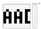
ここで、図5及び図6を参照して、画像属性情報の判定方法について説明する。図5に示すように、各タイル画像領域内の画素を参照して、ライン毎のエッジ数を算出し、各ラインのエッジの総数によって、文字/細線、ベタ画像、それ以外のイメージの各画像属性を判定する。図6にエッジ数算出方法を示す。説明を簡略化するため、10x10画素のブロック画像について説明すると、図6に示すとおり、各0から9までのラインごとのエッジ数は、0,0,4,7,7,3,7,7,0,0となり、各ラインのエッジの総数は35となる。ここでエッジとは、画像のエッジを示す。したがって、2ライン目のエッジは、0画素目と1画素目との間、2画素目と3画素目との間、5画素目と6画素目との間、7画素目と8画素目の間に存在するため、エッジ数が4となる。エッジの総数が0〜5の範囲内がベタ画像、6〜20の範囲内がイメージ、21以上の場合は文字の属性と判定する場合、図6に示すブロック画像(タイル画像)は、エッジの総数が35となるため、文字属性と判定される。判定された画像属性情報はタイル画像毎にリスト化される。ここまでのタイル画像ごとの属性判定がS401の処理となる。 Here, a method for determining image attribute information will be described with reference to FIGS. As shown in FIG. 5, the number of edges for each line is calculated with reference to the pixels in each tile image area, and each image of a character / thin line, a solid image, and other images is calculated according to the total number of edges of each line. Determine the attribute. FIG. 6 shows a method for calculating the number of edges. To simplify the description, a block image of 10 × 10 pixels will be described. As shown in FIG. 6, the number of edges for each line from 0 to 9 is 0, 0, 4, 7, 7, 3, 7, 7 , 0, 0, and the total number of edges in each line is 35. Here, the edge indicates an edge of the image. Therefore, the edge of the second line is between the 0th and 1st pixels, between the 2nd and 3rd pixels, between the 5th and 6th pixels, and between the 7th and 8th pixels. Since it exists in between, the number of edges is 4. When it is determined that the total number of edges is a solid image in the range of 0 to 5, an image in the range of 6 to 20 is an image, and a character attribute is 21 or more, the block image (tile image) shown in FIG. Since the total number is 35, it is determined as a character attribute. The determined image attribute information is listed for each tile image. The attribute determination for each tile image so far is the processing of S401.
S402において、優先順位設定部203は、リスト化された画像属性情報を参照して、符号化処理を行う優先順位を判定する。ここで、図7を参照して、優先順位の設定方法について説明する。例えば優先順位が文字、イメージ、ベタの3段階で高くなる例について説明する。各画像属性に対する優先順位フラグ値は、優先順位の高い順に、文字が1、イメージが2、ベタが3の値とする。図7に示すように、リスト化された画像属性情報が、ベタ、文字、文字、文字、…、である場合は、優先順位フラグはそれぞれ、3、1、1、1、…、と設定される。
In step S402, the priority
次に、S403において、画像符号化処理部110は、設定された優先順位フラグを参照して、タイルリスト毎に出力順序を設定する。図7に示すように、まず、優先順位フラグが1のリストに対して、出力順序を設定する。具体的には、優先順位が1であるタイルNoが2、3、4、…のリストについて出力順序が設定され、それぞれ1、2、3、…が設定される。次に、優先順位フラグが2、最後に優先順位フラグが3のリストに対して出力順序が設定される。したがって、設定される出力順序は、42、1、2、3、4、5、43、44、45、16、…と設定する。
Next, in step S403, the image
次に、S404において、タイル生成部204は、設定された出力順序に従ってDLを翻訳してラスタ画像に変換し、ブロック単位毎のタイル画像として出力する。続いて、S405において、パケット生成部205は、後段の画像圧縮部206における動作モードや、タイル画像の座標情報などをヘッダ情報としてタイル画像に付加して、パケットを生成する。
In step S <b> 404, the
ここで、図8を参照して、パケット生成部205によって生成されるパケット構造について説明する。1パケットは32x32画素の1タイル画像分の画像データを収容するデータ本体1002と、ヘッダ1001から構成される。また、ヘッダ1001は、パケットID1003、圧縮フラグ1004、QテーブルID1005及びデータ長1006の各フィールドを備える。パケットID1003はシリアル番号を示す。圧縮フラグ1004は可変長可逆方式又は固定長非可逆方式のどちらの方式で画像データが圧縮されたかを示す。QテーブルID1005は圧縮する際にどの圧縮率の量子化テーブルを参照されたかを示す。画像データ長1006はデータ本体1002に収容される画像データ量を示す。本実施形態では、パケットID1003が1バイト、圧縮フラグ1004が1ビット、QテーブルID1005が3ビット、画像データ長1006が2バイトである。さらに、ヘッダ1001には、図8に示すように0値を設定する4ビットのフィールドが設けられている。
Here, the packet structure generated by the
次に、図9を参照して、パケット生成部205の詳細について説明する。パケット生成部205は、バッファ2051、マージ回路2052、及びヘッダ生成回路2053を備える。まず、タイル生成部204で生成された画像データがタイル単位でバッファ2051に格納される。ヘッダ生成回路2053は、パケットID1003を順にインクリメントし、QテーブルID1005に対して、圧縮率に応じた量子化テーブルが設定されているIDをセットし、画像データ長1006にデータ量をセットする。生成されたヘッダ情報はマージ回路2052へ出力される。マージ回路2052は、バッファ2051に格納されている画像データを読み出し、ヘッダ情報とマージして、図8に示すフォーマットのパケットを生成する。
Next, the details of the
パケットが生成されると、S406において、画像符号化処理部110は、トータルの符号量が予め設定している閾値より小さいか否かを判定する。トータルの符号量とは、ブロックごとに符号化を実行している際に、現在までに符号化された各ブロックの符号量の総計を示す。また、符号量とは、符号化した画像データを復号化するために必要となるデータ量を示す。ここで、図10を参照して、画像圧縮部206の詳細について説明する。画像圧縮部206は、入力選択部2061、第1圧縮処理部2062、第2圧縮処理部2063、出力選択部2064、及び符号化データ量カウンタ2065を備える。
When the packet is generated, in step S406, the image
まず、画像圧縮部206へ入力されるパケットデータは、入力選択部2061へ入力される。入力選択部2061は、符号化データ量カウンタ2065から供給されるトータルの符号量を参照し、予め定められている閾値と比較する。つまり、符号化データ量カウンタ2065は、現在までに既に符号化されたブロックにおける符号量の総計を算出する符号量算出手段として機能する。ここで、入力選択部2061は、閾値より小さい場合には処理をS407へ移行させるとともに、第1圧縮処理部2062へパケットデータを供給する。一方、入力選択部2061は、それ以外の場合には処理をS408へ移行させるとともに、第2圧縮処理部2063へパケットデータを供給する。
First, packet data input to the
なお、本実施形態によれば、第1圧縮処理部2062が可変長可逆方式の符号化処理を実行し、第2圧縮処理部2063が固定長非可逆方式の符号化処理を実行する。しかし、本発明はこの符号化方式に限定されず、第1圧縮処理部2062及び第2圧縮処理部2063に対して種々の符号化方式を採用してもよい。例えば、第1圧縮処理部2062及び第2圧縮処理部2063ともに可変長符号化方式が採用されてもよい。具体的には、第1圧縮処理部2062は、例えば、可変長非可逆方式のJPEGや可変長で非可逆と可逆の両方式を扱えるJPEG2000などを採用してもよい。また、第2圧縮処理部2063は、例えば、可変長可逆方式のJPEG−LS、GIF、PNGなどを採用してもよい。本発明では、第1圧縮処理部2062が自然画像を得意とする符号化方式を採用し、第2圧縮処理部2063がグラフィック画像を得意とする符号化方式を採用することを意図したものである。
According to the present embodiment, the first
S407において、第1圧縮処理部2062は、第1符号化手段として機能し、可変長可逆方式を用いて符号化処理を実行する。ここで、図11を参照して、第1圧縮処理部2062の構成例とともに、可変長可逆方式の圧縮処理について説明する。第1圧縮処理部2062は、入力バッファ1301、ウェーブレット変換部1302、量子化部1303、EBCOT符号化部1304、出力バッファ1305、及びヘッダ付加部1306を備える。
In step S407, the first
入力バッファ1301は、入力される画像データを格納するためのデータバッファであり、所定量のデータが送られると後段に接続されたウェーブレット変換部1302に対して所定の順序に従ってデータを出力する。ウェーブレット変換部1302では、入力バッファ1301より画像データが入力されると、ウェーブレット変換を行って、各サブバンドのウェーブレット係数に対する微分成分データに変換する。量子化部1303は、ウェーブレット変換部1302より出力される変換データに対して、所定の量子化値を用いて量子化を行う。EBCOT符号化部1304は、量子化部1303から出力されたデータに対して所定の符号化処理を行って符号化データを生成する。出力バッファ1305は、EBCOT符号化部1304からの符号化データの入力が終了すると、符号化されたデータ量を出力するとともに、ヘッダ付加部1306に対して符号化データが出力可能であることを通知する。その後、ヘッダ付加部1306の要求に従って符号化データを出力する。ヘッダ付加部1306は、符号化データと符号化データ量を受信して、ヘッダ情報を付加する。また、ヘッダ付加部1306は、図8に示すヘッダの圧縮フラグ1004に、可変長可逆方式で圧縮したことを示す0をセットし、画像データ長1006に、受信した符号化データ量をセットする。ヘッダを付加された符号化データは、パケットデータとして出力選択部2064へ送信される。このとき出力選択部2064は第1圧縮処理部2062の出力を画像圧縮部206より出力するよう選択する。
The
一方、S406でトータル符号量が閾値以上であると判定されると、S408において、第2圧縮処理部2063は、第2符号化手段として機能し、固定長非可逆方式での符号化処理を行う。ここで、図12を参照して、第2圧縮処理部2063の構成例ととともに、固定長非可逆方式の圧縮処理について説明する。第2圧縮処理部2063は、入力バッファ1401、DCT変換部1402、量子化部1403、ハフマン符号化部1404、出力バッファ1405、ヘッダ付加部1406、量子化テーブル選択部1407、及び量子化テーブル1408を備える。
On the other hand, if it is determined in S406 that the total code amount is equal to or larger than the threshold value, in S408, the second
入力バッファ1401は、入力される画像データを格納するためのデータバッファであり、所定量のデータが送られると後段に接続されたDCT変換部1402に対して所定の順序に従ってデータを出力する。DCT変換部1402では、入力バッファ1401より画像データが入力されると、離散コサイン変換を行って、周波数成分データに変換する。量子化部1403は、DCT変換部1402より出力される変換データに対して、所定の量子化値を用いて量子化を行う。なお、量子化に使用する値は、量子化テーブル選択部1407より入力される。量子化に使用する量子化テーブルは量子化テーブル選択部1407によって、入力バッファ1401に格納されるヘッダ情報のQテーブルID1005を参照することにより決定される。
The
ハフマン符号化部1404は、量子化部1403から出力されたデータに対して所定の符号化処理を行って符号化データを生成する。出力バッファ1405は、ハフマン符号化部1404からの符号化データの入力が終了すると、符号化されたデータ量を出力するとともに、ヘッダ付加部1406に対して符号化データが出力可能であることを通知する。その後、ヘッダ付加部1406の要求に従って符号化データを出力する。ヘッダ付加部1406は、符号化データと符号化データ量を受信して、ヘッダ情報を付加する。図8に示すヘッダの圧縮フラグ1004に、固定長非可逆方式で圧縮したことを示す1をセットし、画像データ長1006に、受信した符号化データ量をセットする。ヘッダを付加された符号化データは、パケットデータとして出力選択部2064へ送信される。このとき出力選択部2064は第2圧縮処理部2063の出力を画像圧縮部206から出力するように選択する。
The
S407又はS408で符号化処理が行われると、S409において、画像符号化処理部110は、符号化された画像データをメモリへ格納する。圧縮された画像データは、メモリ208に予め割り当てられている領域に対して、ヘッダ1001のパケットID1003の順番に従って順次格納される。続いて、S410において、画像符号化処理部110は、全てのタイル画像のメモリ208への格納が終了しているか否かを判定する。ここで、全てのタイル画像の処理が終了している場合は、画像圧縮に関する一連の処理を終了する。一方、まだ全てのタイル画像の処理が終了していない場合には、S404へ戻り、残りのタイル画像に対しての処理を繰り返す。
When the encoding process is performed in S407 or S408, in S409, the image
以上説明したように、本実施形態に係る画像処理装置は、ブロック化(タイル化)した各ブロック画像において、細線や文字などの重要ブロック画像を優先して第1方式で符号化処理を実行する。さらに、画像処理装置は、既に符号化したブロックの符号量が所定の閾値以上になると第2方式で符号化処理を実行する。このように、本実施形態によれば、途中から固定長符号化方式(第2方式)に切り替わっても、既に重要ブロック画像の処理が済んでいる可能性が高くなる。その結果、従来のように画質に大きな影響を与えることなく、符号量を予め定められたメモリ量に抑えることができる。 As described above, the image processing apparatus according to the present embodiment executes encoding processing by the first method with priority on important block images such as thin lines and characters in each block image (tiled). . Further, the image processing apparatus executes the encoding process by the second method when the code amount of the already encoded block exceeds a predetermined threshold. As described above, according to the present embodiment, even when switching to the fixed-length encoding method (second method) from the middle, there is a high possibility that the processing of the important block image has already been completed. As a result, the code amount can be suppressed to a predetermined memory amount without significantly affecting the image quality as in the conventional case.
<第2の実施形態>
次に、図13乃至図15を参照して、第2の実施形態について説明する。本実施形態では、タイル画像中に文字が多く存在するなど、画素値変化量の大きい画像が圧縮対象である場合に、メモリを目標の容量内に圧縮するために、圧縮率を大きくすることを特徴とする。なお、以下では、第1の実施形態と異なる構成や技術について主に説明する。本実施形態ではインタプリタ部202において、画像圧縮部206で使用する量子化テーブルを選択するための、QテーブルIDリストを作成する。
<Second Embodiment>
Next, a second embodiment will be described with reference to FIGS. In this embodiment, when an image with a large amount of change in pixel value is a compression target, such as when there are many characters in the tile image, the compression rate is increased in order to compress the memory within the target capacity. Features. In the following, configurations and techniques different from those of the first embodiment will be mainly described. In the present embodiment, the
まず、図13を参照して、本実施形態における処理が適用されるタイル画像の一例について説明する。図13に示すタイル画像では、各0から9までのラインのエッジ数は、0,0,5,9,9,5,9,8,0,0となり、各ラインにおけるエッジの総数が45となる。ここで第1の実施形態と同様にエッジの総数が0〜5の範囲内をベタ画像と判定し、6〜20の範囲内をイメージと判定し、21以上の場合を文字の属性と判定する。したがって、図13に示すタイル画像は、文字属性と判定される。さらに、本実施形態では、エッジの総数が40以上の場合に、画素値変化量が大きいと判定し、高い圧縮率で圧縮するための量子化テーブルを使用するための、QテーブルIDリストに1が設定される。図14には、本実施形態に係るQテーブルIDリストを示す。図14に示すように、例えば圧縮率の異なる2つの量子化テーブルを使用する場合、大きい圧縮率で量子化する場合はQテーブルIDリストに1が設定され、それ以外のデフォルトの圧縮率でよい場合は0が設定される。
First, an example of a tile image to which the process according to this embodiment is applied will be described with reference to FIG. In the tile image shown in FIG. 13, the number of edges of each line from 0 to 9 is 0, 0, 5, 9, 9, 5, 9, 8, 0, 0, and the total number of edges in each line is 45. Become. Here, as in the first embodiment, the range where the total number of edges is 0 to 5 is determined to be a solid image, the
次に、図15を参照して、本実施形態における符号化処理シーケンスについて説明する。ここでは、図4に示す第1の実施形態と同様の処理については同一のステップ番号を付し、説明を省略する。S1501において、インタプリタ部202は、各ラインエッジ数をカウントする際に、エッジの総数が予め定められた値以上(ここでは、40以上)か否かを判定し、QテーブルIDリストを設定する。つまり、インタプリタ部202は、画素変化量が多いか否かを判定して、タイル画像ごとの圧縮率を決定している。具体的には、インタプリタ部202は、ワークメモリ上に展開されたタイル画素データのエッジの総数をCPU105によりカウントし、予め定められた値以上の場合は、文字数が多いと判断し、予め定められた値より小さい場合には文字数は少ないと判断する。文字数が多い場合は、前述したようにQテーブルIDリストに1を設定し、それ以外の場合は0を設定する。
Next, the encoding processing sequence in the present embodiment will be described with reference to FIG. Here, the same steps as those in the first embodiment shown in FIG. 4 are denoted by the same step numbers, and the description thereof is omitted. In step S1501, the
また、本実施形態によれば、トータル符号量が閾値以上である場合に、S1502において、第2圧縮処理部2063は、各タイル画像ごとに、QテーブルIDリストを参照して、文字数が多いか否かを判定する。ここで、QテーブルIDリストに1が設定されている場合はS1503に進み、0が設定されている場合はS1408に進む。具体的には、第2圧縮処理部2063の量子化テーブル選択部1407が、入力バッファ1401内に格納されている画像データのヘッダ情報のQテーブルID1005を参照する。量子化テーブル選択部1407は、QテーブルID1005が0の場合は、量子化テーブル1408内のデフォルトの圧縮率で設定される量子化テーブルを参照する。QテーブルID1005が1の場合は、圧縮率の高い別の量子化テーブルを参照する。その後、S408において、第2圧縮処理部2063は、量子化テーブル選択部1407によって参照された圧縮率を用いて、固定長非可逆符号化の処理を実行する。このようにQテーブルID1005によって参照する量子化テーブルを切り替えることにより、タイル単位で圧縮処理における圧縮率を切り替える。
Also, according to the present embodiment, when the total code amount is equal to or larger than the threshold, in S1502, the second
以上説明したように、本実施形態における画像処理装置は、第1の実施形態の制御に加えて、文字数(エッジの総数)が多い場合には高い圧縮率に切り替えて符号化処理を実行する。これにより、文字数量が異なるブロックが混在する場合であっても、目標の符号量に収まるよう制御することができる。 As described above, in addition to the control of the first embodiment, the image processing apparatus according to the present embodiment executes the encoding process by switching to a higher compression rate when the number of characters (total number of edges) is large. As a result, even when blocks having different character quantities are mixed, it is possible to perform control so as to be within the target code amount.
<第3の実施形態>
以下では、図16乃至図18を参照して、第3の実施形態について説明する。画像データの符号化を行う際、一般的には画像属性を考慮することなく同じ符号化処理を行っている。そのため、重要でないタイル画像と重要なタイル画像に同じ符号量をメモリ領域に割り当てているのが現状である。そこで、重要でないタイル画像の符号量を減らし、その分を重要なタイル画像の符号量に割り当てることで、メモリ容量を有効に活用でき、画像品位を向上するよう制御することができる。第1の実施形態では画像属性情報を生成しタイル画像毎に優先順位を設定することにより、符号量を調整している。しかし、この方法は予め閾値を設定しているため、メモリ領域をフルに活用できない場合がある。
<Third Embodiment>
The third embodiment will be described below with reference to FIGS. 16 to 18. When encoding image data, the same encoding processing is generally performed without considering image attributes. Therefore, the current situation is that the same code amount is allocated to the memory area for the unimportant tile image and the important tile image. Therefore, by reducing the code amount of an unimportant tile image and allocating that amount to the code amount of an important tile image, the memory capacity can be used effectively and control can be performed to improve the image quality. In the first embodiment, the code amount is adjusted by generating image attribute information and setting the priority order for each tile image. However, since this method sets a threshold value in advance, the memory area may not be fully utilized.
その一例として、ベタ画像が20%、文字画像が80%含まれる画像を想定する。このように、ベタ画像が少なく、文字画像が多い場合には、固定長非可逆方式に割り当てたメモリ領域が余ってしまう場合がある。これは、ベタ画像が少ない場合には固定長非可逆方式のトータル符号量が少ないため、予め設定したメモリの固定長領域が余ってしまうことに起因している。この場合、その余った固定長非可逆方式のメモリ領域を可変長可逆方式のメモリ領域に割り当てることができれば、よりメモリを有効に活用でき、画像品位を向上するよう制御できる。そこで、本実施形態では、画像属性情報を利用して、まず重要でないブロック画像の固定長方式による符号量の合計を推定し、余ったメモリ領域に応じて可変長可逆方式のメモリ領域の所定の閾値を変更する。これにより、重要なブロック画像により多くの可変長可逆方式の符号量を割り当てることができる。 As an example, an image including 20% of a solid image and 80% of a character image is assumed. As described above, when there are few solid images and many character images, the memory area allocated to the fixed-length irreversible method may be left over. This is because, when there are few solid images, the total code amount of the fixed-length irreversible method is small, so that a fixed-length area of a preset memory remains. In this case, if the remaining fixed-length irreversible memory area can be allocated to the variable-length irreversible memory area, the memory can be used more effectively and control can be performed to improve the image quality. Therefore, in the present embodiment, first, the total amount of code of the non-important block image by the fixed length method is estimated using the image attribute information, and a predetermined memory area of the variable length reversible method is determined according to the remaining memory area. Change the threshold. As a result, it is possible to assign more variable-length lossless code amounts to important block images.
図16を参照して、本実施形態に係る画像符号化処理部1600の構成例について説明する。画像符号化処理部1600は、画像符号化処理部110の構成と基本的な構成は同じであるが、さらに、ベタ画像検出部207と、符号量・閾値算出部212とを備える。ベタ画像検出部207は、インタプリタ部202によって生成された属性情報から、ブロック毎に固定長非可逆方式で十分なブロック画像(ここではベタ画像とする。)を検出し、ベタ画像検出フラグを生成する。具体的には、ベタ画像検出部207は、エッジの総数が予め定められた値以下(例えば、5以下)のブロックを固定長非可逆方式で十分なブロック画像として検出する。符号量・閾値算出部212は、ベタ画像検出部207より生成されたベタ画像検出フラグを参照して、ベタ画像を固定長非可逆方式で符号化したときの符号量の合計を推定する。また、その符号量の合計と全メモリ領域から残りのメモリ領域を算出し、可変長可逆方式での符号化の際の所定の閾値を変更する。その他の処理部については第1の実施形態と同様であるため説明を省略する。
A configuration example of the image
次に、図17を参照して、本実施形態における符号化処理シーケンスについて説明する。以下で説明する処理は、CPU105がROM107等からプログラムをロードして実行することにより実現される。なお、以下で記載するSに続く番号は、各フローチャートのステップ番号を示す。また、図4のフローチャートと同様の処理については同一のステップ番号を付し、説明を省略する。
Next, with reference to FIG. 17, the encoding processing sequence in the present embodiment will be described. The processing described below is realized by the
S401で画像属性情報が生成されると、S1701において、ベタ画像検出部207は、リスト化された画像属性情報(文字/細線、イメージ、ベタなど)を参照して、固定長非可逆方式で十分なブロック画像(ここではベタ画像とする)を検出する。さらに、ベタ画像検出部207は、ベタ画像検出フラグを生成する。フラグ値は、固定長非可逆方式で十分なブロック画像(ベタ画像)として検出されたタイル画像は1と設定し、それ以外は0の値を設定する。さらに、ベタ画像検出部207は、ベタ画像検出フラグに基づいてベタ画像検出部207以降のタイル転送順序を決定する。
When the image attribute information is generated in S401, in S1701, the solid
ここで、図18を参照して、ベタ画像検出フラグについて説明する。S1701の処理を実行する段階では、タイル画像毎の属性情報が既に生成されている。したがって、ベタ画像検出部207は、その属性情報に基づいてベタ画像検出フラグの値を決定する。例えば、1番のタイル画像は、属性情報がベタであるため、ベタ画像検出フラグには1が設定される。2番のタイル画像は、属性情報が文字であるため、ベタ画像検出フラグには0が設定される。以下も同様にベタ画像検出フラグが設定される。また、図18では出力番号も記載されているが、これはベタ画像検出フラグが1の値のタイル画像から順番に出力番号を割り振っている。これにより、先にベタ画像を転送しメモリに格納することが可能になる。
Here, the solid image detection flag will be described with reference to FIG. At the stage of executing the processing of S1701, attribute information for each tile image has already been generated. Therefore, the solid
次に、S1702において、符号量・閾値算出部212は、ベタ画像検出フラグを参照してベタ画像を固定長非可逆方式の圧縮で行った場合の符号量の合計を推定する。例えば、予め1ブロックの固定長非可逆方式の符号量を設定しておき、ベタ画像検出フラグが1の値であった場合には、符号量の合計に1タイル画像あたりの符号量を加え、ベタ画像検出フラグが0の値であった場合には、何もしない。この処理を全タイル画像に行うことで固定長非可逆方式の符号量の合計を推定することができる。S1703において、符号量・閾値算出部212は、S1702で推定した符号量から残りのメモリ領域を算出し、残ったブロック画像を圧縮する際の可変長可逆方式の目標閾値を残りのメモリ領域に応じて算出し変更する。このように、まず固定長非可逆方式のトータル符号量を推定してメモリ領域を割り当てることにより、重要なタイル画像に割り当てられる可変長可逆方式の符号量を予め見積もることができる。その後、可変長可逆方式の符号化の閾値を決定することで、予め閾値を設定する場合と比べて可変長可逆方式の符号量を増加させることができる。
In step S <b> 1702, the code amount / threshold
次に、S1704において、タイル生成部204は、32x32のブロック画像をラスタ画像に変換してタイル画像データを生成する。さらに、パケット生成部205は、タイル画像の座標情報などをヘッダ情報としてタイル画像に付加し、パケットを生成する。続いて、S1705において、パケット生成部205は、ベタ画像検出フラグを参照して、フラグの値が1の値のブロックを出力番号に従って画像圧縮部206に転送する。
In step S <b> 1704, the
次に、S1706において、画像圧縮部206は、転送されたブロックを第2圧縮処理部2063により固定長非可逆方式で符号化する。S1707において、画像圧縮部206は、符号化した画像データをメモリへ転送し、格納する。符号化された画像データのメモリ格納は、ブロックごとに処理が終了すると、メモリに順次転送され、格納される。S1708において、画像符号化処理部1600は、ベタ画像が全て固定長非可逆方式で圧縮されメモリに格納されたか否かを判定する。全て終わってない場合には、S1705に戻って残りのベタ画像検出フラグが1のブロック画像を固定長非可逆方式によって圧縮する。全て終わった場合には、S1709に進み、画像符号化処理部1600は、ベタ画像検出フラグが0のブロック画像(ベタ画像以外のブロック画像)の転送を開始する。ここでは、残りのブロックの転送順は特に優先順位を設けず順次転送とするが、例えば第1の実施形態のように優先順位を決定しておき、その優先順位に応じた転送順としてもよい。なお、S406乃至S410の処理は、図4のフローチャートと同様であるため説明を省略する。
In step S <b> 1706, the
以上説明したように、本実施形態における画像処理装置は、重要でないタイル画像(ベタ画像等)を先に固定長符号化方式でメモリ領域を見積もり、メモリ領域をフル活用し残ったメモリ領域に応じて所定の閾値を変更する。これにより、可変長符号化方式での符号化の符号量に対応するメモリ領域を増やすことができる。したがって、本実施形態によれば、残りのメモリ領域をフル活用して、画像品位を向上させることができる。また、本実施形態に係る画像処理装置は、第1の実施形態や第2の実施形態と組み合わせて実現されてもよい。 As described above, the image processing apparatus according to the present embodiment estimates a memory area using a fixed-length encoding method for an unimportant tile image (solid image or the like) first, and uses the memory area in full depending on the remaining memory area. To change the predetermined threshold. As a result, it is possible to increase the memory area corresponding to the code amount of the encoding in the variable length encoding method. Therefore, according to this embodiment, the remaining memory area can be fully utilized to improve the image quality. Further, the image processing apparatus according to the present embodiment may be realized in combination with the first embodiment or the second embodiment.
また、本発明の目的は、以下の処理を実行することによっても達成される。即ち、上述した実施形態の機能を実現するソフトウェアのプログラムコードを記録した記憶媒体を、システム或いは装置に供給し、そのシステム或いは装置のコンピュータ(又はCPUやMPU等)が記憶媒体に格納されたプログラムコードを読み出す処理である。この場合、記憶媒体から読み出されたプログラムコード自体が前述した実施の形態の機能を実現することになり、そのプログラムコード及び該プログラムコードを記憶した記憶媒体は本発明を構成することになる。 The object of the present invention can also be achieved by executing the following processing. That is, a storage medium that records a program code of software that realizes the functions of the above-described embodiments is supplied to a system or apparatus, and a computer (or CPU, MPU, etc.) of the system or apparatus is stored in the storage medium. This is the process of reading the code. In this case, the program code itself read from the storage medium realizes the functions of the above-described embodiments, and the program code and the storage medium storing the program code constitute the present invention.
Claims (9)
入力された画像データにおいて、予め定められたブロック単位ごとの属性情報を生成する属性情報生成手段と、
生成された前記属性情報に基づき、前記ブロック単位で符号化する際の優先順位を設定する優先順位設定手段と、
設定された前記優先順位に従って各ブロックを順番に符号化する際に、既に符号化したブロックにおける符号量の総計を算出する符号量算出手段と、
前記符号量の総計が、使用可能なメモリ領域に応じた所定の閾値より小さい場合に、第1方式を用いて、当該ブロックの画像データを符号化する第1符号化手段と、
前記符号量の総計が前記所定の閾値以上である場合に、前記第1方式よりも符号量が少ない第2方式を用いて、当該ブロックの画像データを符号化する第2符号化手段と
を備えることを特徴とする画像処理装置。 Input means for inputting image data;
Attribute information generating means for generating attribute information for each predetermined block unit in the input image data;
Based on the generated attribute information, priority setting means for setting a priority when encoding in block units;
Code amount calculating means for calculating the total amount of code in the already encoded block when sequentially encoding each block according to the set priority order;
A first encoding means for encoding the image data of the block using the first method when the total amount of the code is smaller than a predetermined threshold according to an available memory area ;
And a second encoding unit that encodes the image data of the block using the second method having a smaller code amount than the first method when the total amount of the code is equal to or greater than the predetermined threshold. An image processing apparatus.
前記ブロック単位ごとに、画素値が変化するエッジの総数を算出するエッジ数算出手段を備え、
算出された前記エッジの総数に基づいて、前記ブロック単位ごとに前記属性情報を生成することを特徴とする請求項1に記載の画像処理装置。 The attribute information generating means
Edge number calculating means for calculating the total number of edges whose pixel values change for each block unit;
The image processing apparatus according to claim 1, wherein the attribute information is generated for each block unit based on the calculated total number of edges.
前記エッジの総数が多い前記属性情報を有するブロックから順に高い優先順位を設定することを特徴とする請求項2に記載の画像処理装置。 The priority order setting means includes:
The image processing apparatus according to claim 2, wherein a higher priority is set in order from a block having the attribute information having a larger total number of edges.
前記エッジの総数が予め定められた値以上のブロックの画像データに対して、前記エッジの総数が前記予め定められた値より小さいブロックの画像データに対して用いられる圧縮率よりも高い圧縮率で符号化することを特徴とする請求項2又は3に記載の画像処理装置。 The second encoding means includes
With respect to the image data of the block whose total number of edges is equal to or greater than a predetermined value, the compression ratio is higher than the compression ratio used for the image data of the block whose total number of edges is smaller than the predetermined value. The image processing apparatus according to claim 2, wherein the image processing apparatus performs encoding.
前記第2符号化手段は、前記第2方式として固定長の符号化方式を用いて符号化処理を実行することを特徴とする請求項2乃至4の何れか1項に記載の画像処理装置。 The first encoding means performs an encoding process using a variable length encoding method as the first method,
5. The image processing apparatus according to claim 2, wherein the second encoding unit executes an encoding process using a fixed-length encoding method as the second method. 6.
推定された前記符号量の合計に従って前記所定の閾値を変更する変更手段と、
前記エッジの総数が予め定められた値以下のブロックの画像データを前記第2符号化手段によって符号化させ、残りのブロックの画像データを、設定された前記優先順位に従って順番に符号化する際に、変更された前記所定の閾値に基づき前記第1符号化手段又は前記第2符号化手段によって符号化させる制御手段と
をさらに備えることを特徴とする請求項5に記載の画像処理装置。 Estimating means for estimating the total amount of code when the second encoding means encodes image data of a block whose total number of edges is a predetermined value or less;
Changing means for changing the predetermined threshold according to a sum of the estimated code amounts;
When the image data of the block whose total number of edges is equal to or less than a predetermined value is encoded by the second encoding means, and the image data of the remaining blocks are encoded in order according to the set priority order The image processing apparatus according to claim 5, further comprising a control unit that performs encoding by the first encoding unit or the second encoding unit based on the changed predetermined threshold.
前記第2符号化手段は、前記第2方式として非可逆の符号化方式を用いて符号化処理を実行することを特徴とする請求項2乃至6の何れか1項に記載の画像処理装置。 The first encoding means performs an encoding process using a reversible encoding method as the first method,
The image processing apparatus according to claim 2, wherein the second encoding unit performs an encoding process using an irreversible encoding method as the second method.
属性情報生成手段が、入力された画像データにおいて、予め定められたブロック単位ごとの属性情報を生成する属性情報生成ステップと、
優先順位設定手段が、生成された前記属性情報に基づき、前記ブロック単位で符号化する際の優先順位を設定する優先順位設定ステップと、
符号量算出手段が、設定された前記優先順位に従って各ブロックを順番に符号化する際に、既に符号化したブロックにおける符号量の総計を算出する符号量算出ステップと、
第1符号化手段が、前記符号量の総計が、使用可能なメモリ領域に応じた所定の閾値より小さい場合に、第1方式を用いて、当該ブロックの画像データを符号化する第1符号化ステップと、
第2符号化手段が、前記符号量の総計が前記所定の閾値以上である場合に、前記第1方式よりも符号量が少ない第2方式を用いて、当該ブロックの画像データを符号化する第2符号化ステップと
を実行することを特徴とする画像処理装置の制御方法。 An input step in which the input means inputs image data;
An attribute information generating step for generating attribute information for each predetermined block unit in the input image data;
A priority order setting means for setting a priority order when encoding in units of blocks based on the generated attribute information;
A code amount calculating step for calculating the total amount of code in the already encoded block when the code amount calculating means sequentially encodes each block according to the set priority;
A first encoding unit configured to encode the image data of the block using the first method when the total amount of the codes is smaller than a predetermined threshold corresponding to an available memory area ; Steps,
The second encoding means encodes the image data of the block using the second method having a smaller code amount than the first method when the total code amount is equal to or greater than the predetermined threshold. A control method for an image processing apparatus, wherein the two encoding steps are executed.
Priority Applications (2)
| Application Number | Priority Date | Filing Date | Title |
|---|---|---|---|
| JP2009265531A JP5524584B2 (en) | 2009-11-20 | 2009-11-20 | Image processing apparatus and control method thereof |
| US12/911,819 US20110123127A1 (en) | 2009-11-20 | 2010-10-26 | Image processing apparatus, control method for the same, program |
Applications Claiming Priority (1)
| Application Number | Priority Date | Filing Date | Title |
|---|---|---|---|
| JP2009265531A JP5524584B2 (en) | 2009-11-20 | 2009-11-20 | Image processing apparatus and control method thereof |
Publications (3)
| Publication Number | Publication Date |
|---|---|
| JP2011109618A JP2011109618A (en) | 2011-06-02 |
| JP2011109618A5 JP2011109618A5 (en) | 2013-01-10 |
| JP5524584B2 true JP5524584B2 (en) | 2014-06-18 |
Family
ID=44062130
Family Applications (1)
| Application Number | Title | Priority Date | Filing Date |
|---|---|---|---|
| JP2009265531A Expired - Fee Related JP5524584B2 (en) | 2009-11-20 | 2009-11-20 | Image processing apparatus and control method thereof |
Country Status (2)
| Country | Link |
|---|---|
| US (1) | US20110123127A1 (en) |
| JP (1) | JP5524584B2 (en) |
Families Citing this family (15)
| Publication number | Priority date | Publication date | Assignee | Title |
|---|---|---|---|---|
| JP2011254405A (en) | 2010-06-03 | 2011-12-15 | Canon Inc | Image processor and image processing method |
| KR20140092861A (en) * | 2011-10-31 | 2014-07-24 | 미쓰비시덴키 가부시키가이샤 | Moving picture encoding device, moving picture decoding device, moving picture encoding method, and moving picture decoding method |
| JP5956180B2 (en) * | 2012-02-24 | 2016-07-27 | ハンファテクウィン株式会社Hanwha Techwin Co.,Ltd. | Encoding apparatus and encoding method |
| KR101953133B1 (en) * | 2012-02-27 | 2019-05-22 | 삼성전자주식회사 | Apparatus and method for rendering |
| JP6029344B2 (en) * | 2012-06-20 | 2016-11-24 | キヤノン株式会社 | Image processing apparatus, image processing method, and program |
| US9754560B2 (en) * | 2012-08-20 | 2017-09-05 | Open Invention Network, Llc | Pooling and tiling data images from memory to draw windows on a display device |
| CN104662900B (en) | 2012-09-19 | 2018-02-13 | 日本电气株式会社 | video image encoding apparatus |
| US9299166B2 (en) * | 2012-12-13 | 2016-03-29 | Qualcomm Incorporated | Image compression method and apparatus for bandwidth saving |
| JP5813024B2 (en) * | 2013-01-29 | 2015-11-17 | 京セラドキュメントソリューションズ株式会社 | Image processing device |
| JP6196117B2 (en) * | 2013-10-08 | 2017-09-13 | 株式会社東芝 | Image encoding apparatus and image decoding apparatus |
| JP6896413B2 (en) * | 2016-12-16 | 2021-06-30 | キヤノン株式会社 | Image processing equipment, image processing methods, and programs |
| WO2018159677A1 (en) * | 2017-03-01 | 2018-09-07 | 日本電信電話株式会社 | Data processing device, network system, packet order control circuit and data processing method |
| JP6986678B2 (en) * | 2017-07-10 | 2021-12-22 | パナソニックIpマネジメント株式会社 | Video signal processing device and video signal transmission system |
| WO2019133052A1 (en) * | 2017-12-28 | 2019-07-04 | Yang Shao Wen | Visual fog |
| CN110113614B (en) * | 2019-05-13 | 2022-04-12 | 格兰菲智能科技有限公司 | Image processing method and image processing apparatus |
Family Cites Families (7)
| Publication number | Priority date | Publication date | Assignee | Title |
|---|---|---|---|---|
| KR950002658B1 (en) * | 1992-04-11 | 1995-03-24 | 주식회사금성사 | Condensation incoding and decoding apparatus of image signal |
| JP3447771B2 (en) * | 1993-09-02 | 2003-09-16 | 富士通株式会社 | Image data encoding method and restoration method and apparatus |
| JPH09168092A (en) * | 1995-12-14 | 1997-06-24 | Ricoh Co Ltd | Image processing unit |
| JPH1051642A (en) * | 1996-07-31 | 1998-02-20 | Fuji Xerox Co Ltd | Image processor |
| JPH10108011A (en) * | 1996-10-01 | 1998-04-24 | Konica Corp | Data-processing unit |
| JP3843581B2 (en) * | 1998-03-05 | 2006-11-08 | 富士ゼロックス株式会社 | Image encoding device, image decoding device, image processing device, image encoding method, image decoding method, and image processing method |
| JP4888335B2 (en) * | 2007-10-25 | 2012-02-29 | ソニー株式会社 | Encoding method and apparatus, and program |
-
2009
- 2009-11-20 JP JP2009265531A patent/JP5524584B2/en not_active Expired - Fee Related
-
2010
- 2010-10-26 US US12/911,819 patent/US20110123127A1/en not_active Abandoned
Also Published As
| Publication number | Publication date |
|---|---|
| US20110123127A1 (en) | 2011-05-26 |
| JP2011109618A (en) | 2011-06-02 |
Similar Documents
| Publication | Publication Date | Title |
|---|---|---|
| JP5524584B2 (en) | Image processing apparatus and control method thereof | |
| JP4533043B2 (en) | Image encoding apparatus and method, computer program, and computer-readable storage medium | |
| EP1271926B1 (en) | Image processing method, apparatus and computer program for compression-encoding | |
| US7561749B2 (en) | Apparatus, method, and computer-readable storage medium for lossy and lossless encoding of image data in accordance with an attribute of the image data | |
| US7454070B2 (en) | Image encoding apparatus and method, computer program, and computer-readable storage medium | |
| US20030031371A1 (en) | Image encoding apparatus and image decoding apparatus | |
| US7468803B2 (en) | Image processing apparatus and image processing method | |
| JP5595151B2 (en) | Image processing apparatus, compression method in image processing apparatus, and program | |
| JP4393319B2 (en) | Image encoding apparatus and method, computer program, and computer-readable storage medium | |
| JP2008104164A (en) | Image processor, and image processing method | |
| JP4781198B2 (en) | Image processing apparatus and method, computer program, and computer-readable storage medium | |
| EP2302896A2 (en) | Data processing apparatus and data processing method for compressing image data | |
| JP2016149762A (en) | Computing device, computer program and method | |
| JP3984813B2 (en) | Image processing apparatus and method, computer program, and storage medium | |
| JP2003209698A (en) | Image processing device and method therefor, computer program, and storage medium | |
| JP2004221998A (en) | Image processor | |
| JP2003046789A (en) | Image coding apparatus and image decoding apparatus | |
| JP6741463B2 (en) | Image processing apparatus, image processing method, and program | |
| JP2003101793A (en) | Picture processing system and method for controlling the same and computer program and storage medium | |
| JP4715175B2 (en) | Image forming apparatus and method | |
| JP3190118B2 (en) | Image processing device | |
| JP2002354266A (en) | Image processor, image processing system, image processing method, recording medium, and program | |
| JP2001326930A (en) | Image encoder and image encoding method, and storage medium | |
| JP2020129728A (en) | Image processing device and control method therefor | |
| JP2017087514A (en) | Image processing device, image processing method, and program |
Legal Events
| Date | Code | Title | Description |
|---|---|---|---|
| A521 | Request for written amendment filed |
Free format text: JAPANESE INTERMEDIATE CODE: A523 Effective date: 20121115 |
|
| A621 | Written request for application examination |
Free format text: JAPANESE INTERMEDIATE CODE: A621 Effective date: 20121115 |
|
| A977 | Report on retrieval |
Free format text: JAPANESE INTERMEDIATE CODE: A971007 Effective date: 20131021 |
|
| A131 | Notification of reasons for refusal |
Free format text: JAPANESE INTERMEDIATE CODE: A131 Effective date: 20131025 |
|
| A521 | Request for written amendment filed |
Free format text: JAPANESE INTERMEDIATE CODE: A523 Effective date: 20131217 |
|
| TRDD | Decision of grant or rejection written | ||
| A01 | Written decision to grant a patent or to grant a registration (utility model) |
Free format text: JAPANESE INTERMEDIATE CODE: A01 Effective date: 20140314 |
|
| A61 | First payment of annual fees (during grant procedure) |
Free format text: JAPANESE INTERMEDIATE CODE: A61 Effective date: 20140410 |
|
| LAPS | Cancellation because of no payment of annual fees |