JP4393319B2 - Image encoding apparatus and method, computer program, and computer-readable storage medium - Google Patents
Image encoding apparatus and method, computer program, and computer-readable storage medium Download PDFInfo
- Publication number
- JP4393319B2 JP4393319B2 JP2004261565A JP2004261565A JP4393319B2 JP 4393319 B2 JP4393319 B2 JP 4393319B2 JP 2004261565 A JP2004261565 A JP 2004261565A JP 2004261565 A JP2004261565 A JP 2004261565A JP 4393319 B2 JP4393319 B2 JP 4393319B2
- Authority
- JP
- Japan
- Prior art keywords
- encoding
- image
- encoded data
- data
- memory
- Prior art date
- Legal status (The legal status is an assumption and is not a legal conclusion. Google has not performed a legal analysis and makes no representation as to the accuracy of the status listed.)
- Expired - Fee Related
Links
Images


Classifications
-
- H—ELECTRICITY
- H04—ELECTRIC COMMUNICATION TECHNIQUE
- H04N—PICTORIAL COMMUNICATION, e.g. TELEVISION
- H04N19/00—Methods or arrangements for coding, decoding, compressing or decompressing digital video signals
- H04N19/42—Methods or arrangements for coding, decoding, compressing or decompressing digital video signals characterised by implementation details or hardware specially adapted for video compression or decompression, e.g. dedicated software implementation
- H04N19/436—Methods or arrangements for coding, decoding, compressing or decompressing digital video signals characterised by implementation details or hardware specially adapted for video compression or decompression, e.g. dedicated software implementation using parallelised computational arrangements
-
- H—ELECTRICITY
- H04—ELECTRIC COMMUNICATION TECHNIQUE
- H04N—PICTORIAL COMMUNICATION, e.g. TELEVISION
- H04N19/00—Methods or arrangements for coding, decoding, compressing or decompressing digital video signals
- H04N19/10—Methods or arrangements for coding, decoding, compressing or decompressing digital video signals using adaptive coding
- H04N19/102—Methods or arrangements for coding, decoding, compressing or decompressing digital video signals using adaptive coding characterised by the element, parameter or selection affected or controlled by the adaptive coding
- H04N19/12—Selection from among a plurality of transforms or standards, e.g. selection between discrete cosine transform [DCT] and sub-band transform or selection between H.263 and H.264
-
- H—ELECTRICITY
- H04—ELECTRIC COMMUNICATION TECHNIQUE
- H04N—PICTORIAL COMMUNICATION, e.g. TELEVISION
- H04N19/00—Methods or arrangements for coding, decoding, compressing or decompressing digital video signals
- H04N19/10—Methods or arrangements for coding, decoding, compressing or decompressing digital video signals using adaptive coding
- H04N19/102—Methods or arrangements for coding, decoding, compressing or decompressing digital video signals using adaptive coding characterised by the element, parameter or selection affected or controlled by the adaptive coding
- H04N19/124—Quantisation
-
- H—ELECTRICITY
- H04—ELECTRIC COMMUNICATION TECHNIQUE
- H04N—PICTORIAL COMMUNICATION, e.g. TELEVISION
- H04N19/00—Methods or arrangements for coding, decoding, compressing or decompressing digital video signals
- H04N19/10—Methods or arrangements for coding, decoding, compressing or decompressing digital video signals using adaptive coding
- H04N19/134—Methods or arrangements for coding, decoding, compressing or decompressing digital video signals using adaptive coding characterised by the element, parameter or criterion affecting or controlling the adaptive coding
- H04N19/146—Data rate or code amount at the encoder output
- H04N19/15—Data rate or code amount at the encoder output by monitoring actual compressed data size at the memory before deciding storage at the transmission buffer
-
- H—ELECTRICITY
- H04—ELECTRIC COMMUNICATION TECHNIQUE
- H04N—PICTORIAL COMMUNICATION, e.g. TELEVISION
- H04N19/00—Methods or arrangements for coding, decoding, compressing or decompressing digital video signals
- H04N19/10—Methods or arrangements for coding, decoding, compressing or decompressing digital video signals using adaptive coding
- H04N19/134—Methods or arrangements for coding, decoding, compressing or decompressing digital video signals using adaptive coding characterised by the element, parameter or criterion affecting or controlling the adaptive coding
- H04N19/146—Data rate or code amount at the encoder output
- H04N19/152—Data rate or code amount at the encoder output by measuring the fullness of the transmission buffer
-
- H—ELECTRICITY
- H04—ELECTRIC COMMUNICATION TECHNIQUE
- H04N—PICTORIAL COMMUNICATION, e.g. TELEVISION
- H04N19/00—Methods or arrangements for coding, decoding, compressing or decompressing digital video signals
- H04N19/10—Methods or arrangements for coding, decoding, compressing or decompressing digital video signals using adaptive coding
- H04N19/169—Methods or arrangements for coding, decoding, compressing or decompressing digital video signals using adaptive coding characterised by the coding unit, i.e. the structural portion or semantic portion of the video signal being the object or the subject of the adaptive coding
- H04N19/17—Methods or arrangements for coding, decoding, compressing or decompressing digital video signals using adaptive coding characterised by the coding unit, i.e. the structural portion or semantic portion of the video signal being the object or the subject of the adaptive coding the unit being an image region, e.g. an object
- H04N19/172—Methods or arrangements for coding, decoding, compressing or decompressing digital video signals using adaptive coding characterised by the coding unit, i.e. the structural portion or semantic portion of the video signal being the object or the subject of the adaptive coding the unit being an image region, e.g. an object the region being a picture, frame or field
-
- H—ELECTRICITY
- H04—ELECTRIC COMMUNICATION TECHNIQUE
- H04N—PICTORIAL COMMUNICATION, e.g. TELEVISION
- H04N19/00—Methods or arrangements for coding, decoding, compressing or decompressing digital video signals
- H04N19/10—Methods or arrangements for coding, decoding, compressing or decompressing digital video signals using adaptive coding
- H04N19/169—Methods or arrangements for coding, decoding, compressing or decompressing digital video signals using adaptive coding characterised by the coding unit, i.e. the structural portion or semantic portion of the video signal being the object or the subject of the adaptive coding
- H04N19/17—Methods or arrangements for coding, decoding, compressing or decompressing digital video signals using adaptive coding characterised by the coding unit, i.e. the structural portion or semantic portion of the video signal being the object or the subject of the adaptive coding the unit being an image region, e.g. an object
- H04N19/176—Methods or arrangements for coding, decoding, compressing or decompressing digital video signals using adaptive coding characterised by the coding unit, i.e. the structural portion or semantic portion of the video signal being the object or the subject of the adaptive coding the unit being an image region, e.g. an object the region being a block, e.g. a macroblock
-
- H—ELECTRICITY
- H04—ELECTRIC COMMUNICATION TECHNIQUE
- H04N—PICTORIAL COMMUNICATION, e.g. TELEVISION
- H04N19/00—Methods or arrangements for coding, decoding, compressing or decompressing digital video signals
- H04N19/10—Methods or arrangements for coding, decoding, compressing or decompressing digital video signals using adaptive coding
- H04N19/189—Methods or arrangements for coding, decoding, compressing or decompressing digital video signals using adaptive coding characterised by the adaptation method, adaptation tool or adaptation type used for the adaptive coding
- H04N19/192—Methods or arrangements for coding, decoding, compressing or decompressing digital video signals using adaptive coding characterised by the adaptation method, adaptation tool or adaptation type used for the adaptive coding the adaptation method, adaptation tool or adaptation type being iterative or recursive
-
- H—ELECTRICITY
- H04—ELECTRIC COMMUNICATION TECHNIQUE
- H04N—PICTORIAL COMMUNICATION, e.g. TELEVISION
- H04N19/00—Methods or arrangements for coding, decoding, compressing or decompressing digital video signals
- H04N19/42—Methods or arrangements for coding, decoding, compressing or decompressing digital video signals characterised by implementation details or hardware specially adapted for video compression or decompression, e.g. dedicated software implementation
- H04N19/423—Methods or arrangements for coding, decoding, compressing or decompressing digital video signals characterised by implementation details or hardware specially adapted for video compression or decompression, e.g. dedicated software implementation characterised by memory arrangements
-
- H—ELECTRICITY
- H04—ELECTRIC COMMUNICATION TECHNIQUE
- H04N—PICTORIAL COMMUNICATION, e.g. TELEVISION
- H04N19/00—Methods or arrangements for coding, decoding, compressing or decompressing digital video signals
- H04N19/60—Methods or arrangements for coding, decoding, compressing or decompressing digital video signals using transform coding
Landscapes
- Engineering & Computer Science (AREA)
- Multimedia (AREA)
- Signal Processing (AREA)
- Computing Systems (AREA)
- Theoretical Computer Science (AREA)
- Physics & Mathematics (AREA)
- Discrete Mathematics (AREA)
- General Physics & Mathematics (AREA)
- Compression Of Band Width Or Redundancy In Fax (AREA)
- Compression Or Coding Systems Of Tv Signals (AREA)
- Image Processing (AREA)
Description
本発明は、画像データを符号化する技術に関するものである。 The present invention relates to a technique for encoding image data.
従来、静止画像の圧縮方式には、離散コサイン変換を利用したJPEG方式や、Wavelet変換を利用した方式が多く使われている。この種の符号化方式は、可変長符号化方式であるので、符号化対象の画像毎に符号量が変化するものである。 Conventionally, as a still image compression method, a JPEG method using discrete cosine transform and a method using Wavelet transform are often used. Since this type of encoding method is a variable-length encoding method, the code amount changes for each image to be encoded.
国際標準化方式であるJPEG方式では、画像に対して1組の量子化マトリクスしか定義できないので、プリスキャン無しには、符号量調整が行えず、限られたメモリに記憶するシステムで使用する場合においては、メモリオーバーを起こす危険性があった。 In the JPEG method, which is an international standardization method, only one set of quantization matrices can be defined for an image. Therefore, the code amount cannot be adjusted without pre-scanning and used in a system that stores in a limited memory. There was a danger of causing memory over.
これを防止するために、予定した符号量よりオーバーした場合は、圧縮率を変更して、原稿の再読み込みを行なう方法や、予めプリスキャンによる符号量見積もりを行ない、符号量を調整するために、量子化パラメータの再設定を行なう方法などがとられていた。 In order to prevent this, in order to adjust the code amount by changing the compression rate and re-reading the original when the code amount exceeds the planned code amount, or by estimating the code amount by pre-scanning in advance For example, a method of resetting the quantization parameter has been used.
従来、プリスキャンを行う符号量制御方式として、例えば、プリ圧縮したデータを内部バッファメモリに入れ、これを伸長し、圧縮パラメータを変え、本圧縮し、外部記憶に出力する方式が知られている。このとき、本圧縮は、プリ圧縮よりも圧縮率を高めにする必要がある。 Conventionally, as a code amount control method for performing pre-scanning, for example, a method in which pre-compressed data is stored in an internal buffer memory, decompressed, changed in compression parameters, subjected to main compression, and output to an external storage is known. . At this time, the main compression needs to have a higher compression rate than the pre-compression.
また、例えば、画素ブロックごとの許容符号量を求め、符号量を減らすために、DCT係数をn回レベルシフトした係数をハフマン符号化する方式が知られており、このシフト量nは許容符号量から決定される。 Further, for example, in order to obtain an allowable code amount for each pixel block and reduce the code amount, a method of performing Huffman coding on a coefficient obtained by level-shifting a DCT coefficient n times is known, and this shift amount n is an allowable code amount. Determined from.
また、一度の画像入力により、効果的にサイズに収まる符号化データを生成する方法もある(特許文献1)。この手法は、符号化データを格納するための2つのメモリを用意し、生成された符号化データを両メモリに格納していくものである。そして、格納した符号化データ量が目標データ量に到達したとき、より高い圧縮率となるような大きな量子化ステップを設定すると共に、一方のメモリ(第1のメモリ)をクリアする。これにより、目標データ量に到達した以降の符号化の圧縮率と高くする。また、もう一方のメモリ(第2のメモリ)には、発生した符号量が目標データ量に到達する以前の符号化データが格納されているので、更に高い量子化ステップで再符号化を行い、再符号化結果を第1のメモリに格納する。そして、この処理を、データ量が目標データ量に達する毎に繰り返るものである。 In addition, there is a method for generating encoded data that effectively fits in the size by one-time image input (Patent Document 1). This method prepares two memories for storing encoded data, and stores the generated encoded data in both memories. Then, when the stored encoded data amount reaches the target data amount, a large quantization step is set so that a higher compression rate is obtained, and one memory (first memory) is cleared. Thereby, the compression rate of encoding after reaching the target data amount is increased. The other memory (second memory) stores encoded data before the generated code amount reaches the target data amount, so re-encoding is performed at a higher quantization step. The re-encoding result is stored in the first memory. This process is repeated every time the data amount reaches the target data amount.
また、これら非可逆方式のみでなく、可逆符号化方式を取り入れて、文字画像や、線画等の非自然画等に可逆符号化方式を用い、自然画部に非可逆符号化方式を用いる方法がとられている。これらはあらかじめその画像の部分部分において属性を判定しておき、その判定結果を用いて符号化方式を切り替える方法がとられている(特許文献2)。 In addition to these irreversible methods, there is a method that adopts a reversible coding method, uses a reversible coding method for character images, non-natural images such as line drawings, etc., and uses a irreversible coding method for natural image portions. It has been taken. In these methods, a method is adopted in which attributes are determined in advance in a partial portion of the image, and the encoding method is switched using the determination result (Patent Document 2).
一方で、上記特許文献1の様な、符号化途中の符号化データ量に応じて再符号化を実行する技術ではないが、画像中の複数の領域において、可逆と非可逆の符号化の何れか一方を選択的に適用しつつ、画像全体を一定の符号量とする技術もある(特許文献3)。
しかしながら、上記の特許文献1における圧縮符号化技術はJPEG等の非可逆圧縮技術のみが用いられる。従って、データ量が所定サイズに収まらなかった場合には、量子化ステップをより大きなものとし、画像全体の圧縮率を一律に引き上げることになり、画像劣化を引き起こす可能性が高い。特に、文字線画及び自然画混在した画像を圧縮符号化する場合、自然画については量子化ステップの引き上げの影響は少なくても、文字線画での影響は無視できない。
However, only the irreversible compression technique such as JPEG is used as the compression encoding technique in the above-mentioned
かかる点、文字線画については可逆符号化、自然画については非可逆符号化を行うことで、それぞれの像域に特化した符号化が行えることにより、画質的に優れた符号化が期待できる。しかしながら、これを実現するためには、前処理としてそれら画像の属性判断処理を行う必要があるし、その正確な属性判定が必須になる。 In this respect, by performing lossless encoding for character / line images and irreversible encoding for natural images, encoding specialized for each image area can be performed, so that excellent image quality can be expected. However, in order to realize this, it is necessary to perform attribute determination processing of these images as preprocessing, and accurate attribute determination is essential.
本発明は上記従来例に鑑みて成されたものであり、格別な像域判定技術を用いずとも、文字線画、自然画が混在した画像を効率良く圧縮符号化するだけでなく、画質的にも優れた符号化データを生成する技術を提供するものである。 The present invention has been made in view of the above-described conventional example, and not only efficiently compresses and encodes an image in which character line images and natural images are mixed without using a special image area determination technique, but also in terms of image quality. Provides a technique for generating encoded data.
この課題を解決するため、例えば本発明の画像符号化装置は以下の構成を備える。すなわち、
画像データを符号化する画像符号化装置であって、
符号化対象の画像データから、複数画素で構成される画像ブロックデータを単位に入力する入力手段と、
入力した画像ブロックデータを非可逆符号化し、非可逆の符号化データを生成する第1の符号化手段と、
入力した前記画像ブロックデータを可逆符号化し、可逆の符号化データを生成する第2の符号化手段と、
前記第2の符号化手段で生成された符号化データの符号長をLx、前記第1の符号化手段で生成された符号化データの符号長をLyとし、所定の非線形境界関数f()関数に対し、
条件: Ly≧f(Lx)
を満たす場合に、前記第2の符号化手段で生成された符号化データを選択して出力し、前記非線形境界関数の前記条件を満たさない場合には第1の符号化手段で生成された符号化データを選択して出力する選択手段とを備え、
X軸を前記第2符号化手段で生成される符号化データの符号長、Y軸を前記第1の符号化手段で生成される符号化データの符号長とするX−Y座標空間において、
予め用意された文字線画、自然画、及び、濃度のグラデーションを持つ画像の3つ種類の画像を、前記第1,第2の符号化手段で符号化して得られたそれぞれの画素ブロックデータの符号化データの符号長Ly、Lxで特定される座標(Lx,Ly)を前記X−Y座標空間にプロットした場合の前記文字線画、自然画、及び、濃度のグラデーションを持つ画像のプロット領域をT,I,Gと定義したとき、
前記非線形境界関数f()は、前記X−Y座標の原点を通り、プロット領域Gとプロット領域Iの間を通る曲線部と、プロット領域Tとプロット領域Iとを間を通る線形部を有する。
In order to solve this problem, for example, an image encoding device of the present invention has the following configuration. That is,
An image encoding device for sign-the image data,
Input means for inputting image block data composed of a plurality of pixels in units of image data to be encoded;
Lossy encoding the input image block data, a first encoding means for producing a lossy encoded data,
And lossless encoding said image block data input, a second encoding means for generating a lossless encoded data,
The code length of the encoded data generated by the second encoding means is Lx, the code length of the encoded data generated by the first encoding means is Ly, and a predetermined nonlinear boundary function f () function Whereas
Condition: Ly ≧ f (Lx)
If the condition is satisfied, the encoded data generated by the second encoding unit is selected and output. If the condition of the nonlinear boundary function is not satisfied, the code generated by the first encoding unit is selected. Selecting means for selecting and outputting the digitized data,
In the XY coordinate space where the X axis is the code length of the encoded data generated by the second encoding means, and the Y axis is the code length of the encoded data generated by the first encoding means,
Codes of respective pixel block data obtained by encoding the three types of images prepared in advance by the first and second encoding means: a character line image, a natural image, and an image having a gradation of density. A plot area of the character line image, natural image, and image having a gradation of density when the coordinates (Lx, Ly) specified by the code lengths Ly and Lx of the digitized data are plotted in the XY coordinate space is represented by T , I, and G,
The nonlinear boundary function f () has a curved portion passing through the origin of the XY coordinates, passing between the plot region G and the plot region I, and a linear portion passing between the plot region T and the plot region I. .
本発明によれば、可逆符号化データ並びに非可逆符号化データが混在しつつ、復号画像の画質劣化を少なくできるようになる。 According to the present invention, it is possible to reduce the image quality degradation of the decoded image while the lossless encoded data and the lossy encoded data are mixed.
以下、図面に従って本発明に係る実施形態を詳細に説明する。 Hereinafter, embodiments according to the present invention will be described in detail with reference to the drawings.
<装置概要の説明>
図22は、実施形態が適用する複写機のブロック構成図である。
<Description of device outline>
FIG. 22 is a block diagram of a copying machine to which the embodiment is applied.
図中、1は装置全体の制御を司る制御部であり、CPU、ROM、RAM等で構成される。2はLCD表示器や各種スイッチ、ボタン等で構成される操作部である。3は原稿読取部(イメージスキャナ部)であり、ADF(Auto Document Feeder)を搭載している。読取った画像はRGB各色成分毎に8ビット(256階調)のデジタルデータを出力する。4は、不図示のインタフェース(ネットワークインタフェースを含む)を介して受信したPDL形式の印刷データに基づき、印刷画像を描画するレンダリング部である。5はセレクタであり、制御部1からの指示に従って、原稿読取部3、又は、レンダリング部4から出力されたビットマップイメージのいずれか一方を選択し、出力する。
In the figure,
6は本実施形態の特徴部分である符号化処理部である。この符号化処理部6の詳細な後述するが、画像データの符号化するものである。
7は2次記憶装置(実施形態ではハードディスク装置とする)であり、符号化処理部6より出力された符号化データを順に格納記憶する。
Reference numeral 7 denotes a secondary storage device (in the embodiment, a hard disk device), which sequentially stores and stores encoded data output from the
8は、復号処理部であって、2次記憶装置7に格納された圧縮符号化された画像データを、その格納順に読出し、復号する。9は画像処理部であって、復号処理部8からの復号画像を入力し、RGB色空間を記録色空間であるYMCへの変換、UCR(Under Color Removal)処理を行うと共に、画像データの補正処理を行う。
10はプリンタエンジン部である。プリンタエンジン部の印刷機構は、レーザビームプリンタエンジンとするが、インク液を吐出するタイプでも構わず、その種類は問わない。
上記構成において、例えば、利用者が操作部2を操作して、複写モードを選択し、原稿を原稿読取部3(のADF)にセットし、複写開始キーを押下すると、原稿読取部3で読取られた原稿画像データは、ラスター順に、セレクタ5を介して符号化処理部6に転送され、ここで圧縮符号化されて2次記憶装置7に格納していく。
In the above configuration, for example, when the user operates the
また、外部より印刷データを受信した場合には、セレクタ5をレンダリング部4を選択するようにし、レンダリング部4が生成した印刷データに基づく画像を圧縮符号化し、2次記憶装置7に格納することになる。
Further, when print data is received from the outside, the
復号処理部8は、プリンタエンジン10の印刷速度に応じて、2次記憶装置7から圧縮符号化データを読出し、復号処理する。そして、画像処理部9で復号した画像データからYMCK成分の記録用画像データを生成する。そして、その結果をプリンタエンジン部10に出力し、印刷を行う。
The
上記の通り、2次記憶装置7への圧縮符号化データの格納処理と、復号し印刷するための読出し処理は、非同期である。つまり、2次記憶装置7は画像圧縮処理と、復号処理との間に介在するバッファとして機能することになり、原稿読取り/符号化処理は、復号/記録処理に非依存なので、多数の原稿を高速に読取ることができ、次のジョブの原稿読取りにすばやく移行することが可能になる。 As described above, the compressed encoded data storage process in the secondary storage device 7 and the read process for decoding and printing are asynchronous. In other words, the secondary storage device 7 functions as a buffer interposed between the image compression process and the decoding process, and the document reading / encoding process is independent of the decoding / recording process. Scanning can be performed at high speed, and it is possible to quickly shift to document reading for the next job.
以上、実施形態における装置全体の構成について説明した。次に、本装置の特徴部分である符号化処理部6について説明する。
The configuration of the entire apparatus in the embodiment has been described above. Next, the
<符号化部の説明>
図1は実施形態における符号化処理部6のブロック構成図である。
<Description of Encoding Unit>
FIG. 1 is a block diagram of the
入力部101は、複数ライン分のラインバッファーメモリを内蔵し、先に説明したように、セレクタ5を介して、原稿読取部3もしくはレンダリング部4からの画像データをラスター順に入力し、内部のラインバッファーに格納し、N×M画素ブロック(実施形態では8×8画素ブロックとした)単位に出力する。
The
第1の符号化部102は非可逆符号化部であって、圧縮率に影響を与えるパラメータに従って、入力部101より入力した画素ブロック単位に圧縮符号化処理を行い、その結果(符号化データ)を出力する。但し、符号化データの先頭には、第1の符号化部102で符号化されたことを示す識別ビットを付加する。
The
実施形態における、この画像符号化部102は、JPEG符号化(不可逆符号化)を適用した例を説明する。つまり、8×8画素単位に相当する画像データを直行変換し、後述する量子化ステップを用いた量子化し、ハフマン符号化処理を行うものである。ここで生成される符号量を左右するのが量子化ステップであり、これは符号化シーケンス制御部110により設定される。JPEG符号化は、自然画に適した技術として知られている。
In the embodiment, the
図21はDCT変換後の周波数係数を量子化する際に用いる量子化マトリクステーブルQ0、Q1、Q2を示している(符号化シーケンス制御部110に記憶保持されている)。ここで、量子化マトリクステーブル内の値Qi(0,0)〜Qi(7,7)(i=0、1、2…)が量子化ステップ値を意味する。量子化ステップ値は、概ね、Q0<Q1<Q2…の関係にある。量子化ステップ値が大きくなればなるほど、量子化後の周波数係数値の取り得る範囲が狭くなり、圧縮率が向上する。 FIG. 21 shows quantization matrix tables Q0, Q1, and Q2 used when quantizing the frequency coefficients after DCT conversion (stored in the encoding sequence control unit 110). Here, values Qi (0, 0) to Qi (7, 7) (i = 0, 1, 2,...) In the quantization matrix table mean quantization step values. The quantization step values are generally in a relationship of Q0 <Q1 <Q2. The greater the quantization step value, the narrower the range of possible frequency coefficient values after quantization, and the compression rate improves.
第2の符号化部103は、第1の符号化部102と異なり、可逆符号化部である。可逆符号化であるため、その復号結果は符号化する前の画像と同じとなり、原理的に画質の劣化は発生しない。但し、圧縮率に影響を与えるパラメータの設定も無い。実施形態では、この第2の符号化部103にJPEG−LSを用いた。JPEG−LSは「JPEG」を冠するものの、第1の符号化部で採用している非可逆符号化JPEGとはそのアルゴリズムは全く異なる。JPEG−LS符号化の特徴は、文字線画、コンピュータグラフィックスに適した技術であり、これらの画像の場合には、非可逆符号化であるJPEGに与える量子化ステップが“1”(実質可逆)は勿論こと、“2”、“3”等の比較的小さい量子化ステップ値よりも遥かに少ない符号データを生成することができる。
Unlike the
また、第2の符号化部103は、第1の符号化部102と実質的に同じタイミングで、同じ画素ブロックに対して符号化を行い、符号化データを出力する。また、第2の符号化部103は、符号化データを出力する際に、その符号化データの先頭に第2の符号化部102で符号化されたことを示す識別ビットを付加する。
The
第1の符号長検出部108は、第1の符号化部102から出力される画素ブロックの符号化データ長(識別ビットである1ビットを含む)を検出し、符号化シーケンス制御部108に出力する。第2の符号長検出部109は第2の符号化部103から出力される画素ブロックの符号化データ長(識別ビットである1ビットを含む)を検出し、符号化シーケンス制御部108に出力する。
The first code
符号化シーケンス制御部110は実施形態における符号化処理部6の制御を司るものである。その処理の1つに、第1の符号長検出部108、第2の符号長検出部109からの信号と、内蔵したLUT(ルックアップテーブル)120を用いて、第1のメモリ105に格納すべき符号化データを決定する(この選択原理は後述する)。そして、その決定した符号化データを選択させるための選択信号を第1のメモリ制御部104に出力する。
The encoding
また、符号化シーケンス制御部110は、第1のメモリ105に格納することになった符号化データの符号長データを累積カウントする第1のカウンタ110を備える。第1のカウンタ110は、注目ブロックに対応し、且つ、第1のメモリ105に格納される符号化データ長を累積するものであるから、第1のメモリ105に格納された総符号化データ量を示す情報を保持することになる。
In addition, the encoding
また、この符号化シーケンス制御部110は、カウンタ111の値(第1のメモリ105に格納された符号化データ量)と目標データ量(入力画像のサイズに依存して決定されるものとする)との比較を行い、その目標データ量に達した(目標値を超えた)ことを検出した時にメモリ105内の格納済みのデータを廃棄するようメモリ制御部104に制御信号を出力すると共に、カウンタ111をゼロクリアする。また、画像の再入力を制御部1(図22参照)に対して要求する。
In addition, the encoding
このように、カウンタ111の値と目標データ量を超えた場合には、画像データの再入力を行うが、画像データの再入力を行う場合には、それ以前に第1の符号化部102に設定されていた量子化ステップQiを次の段階のQi+1に変更し、圧縮率を向上させるようにして符号化を再開する。
As described above, when the value of the
以上のようにして、カウンタ111の値が目標データ量を超えないまま、1ページの符号化が完了すると、第1のメモリ105には、注目ページの可逆、非可逆の混在した符号化データが生成されることになるが、それを2次記憶装置7に出力する。また、次のページの画像データが存在する(或いは次の原稿が存在する)場合には、その符号化を開始することになる。
As described above, when encoding of one page is completed while the value of the
以上実施形態における符号化処理部6の大まかな処理内容について説明した。次に、実施形態における符号化シーケンス制御部110での、第1のメモリ105に格納する符号化データを決定する原理について説明する。
The rough processing content of the
実施形態では、第1の符号化部102に非可逆符号化であるJPEG、第2の符号化部103に可逆符号化であるJPEG−LSを利用した場合である。JPEGは周知の通り自然画の圧縮に適した符号化技術であるが、文字線画等については圧縮率は高くない。一方、JPEG−LSは、文字線画(カラーを含む)、並びに、単調な棒グラフ等の画像に好適なものであり、尚且つ、可逆符号化であるが故に画像劣化は原理的に発生しない。ただし、JPEG−LSは自然画については圧縮率は高くない。つまり、これら2つの符号化技術は互いに補う関係にある。
In the embodiment, JPEG that is lossy encoding is used for the
ここで、図20に示すような、文字線画領域T1、T2、コンピュータグラフィクスによるグラデーション(濃度がなだらかに変化する画像)領域G、自然画領域Iを含む原稿を読取る場合について考察する。 Consider a case where a document including character / line image areas T1 and T2, a gradation (image whose density changes gently) area G, and a natural image area I are read as shown in FIG.
文字線画領域T1内には、画像のエッジが急峻な文字線画のみが存在し、文字線画T2ではエッジ部分が多少ボケた文字線画のみが存在するものとする。文字線画領域T2は文字や図形のふちを滑らかに見せるためのアンチエイリアス処理をかけたものや、デジタル的な解像度変換を行った場合に相当する。 In the character / line image area T1, only character / line images with sharp edges are present, and in the character / line image T2, only character / line images with slightly blurred edges are present. The character / line drawing region T2 corresponds to a case where anti-aliasing processing is applied to make the edges of characters or figures look smooth, or when digital resolution conversion is performed.
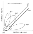
さて、図示の原稿を読取り、8×8画素ブロック単位に可逆符号化して得られた符号化データの符号長をLx、同一画素ブロックを非可逆符号化(量子化ステップQ0)で符号化して得られた符号化データの符号長をLyとし、Lx、Lyを座標とする点P(Lx,Ly)をプロットした結果を示すのが図18である。 Now, the illustrated original is read, and the code length of the encoded data obtained by lossless encoding in units of 8 × 8 pixel blocks is Lx, and the same pixel block is encoded by lossy encoding (quantization step Q0). FIG. 18 shows a result of plotting a point P (Lx, Ly) having the code length of the encoded data as Ly and Lx, Ly as coordinates.
図18における楕円で囲んだ各分布領域2001乃至2005が、上記各領域T1、T2、G、Iのプロットした点の概ねの分布領域を示している。なお、楕円外をプロットすることがあったが、そのようなプロット点は少なく、イレギュラーな点として無視した。また、図示の破線2006はLy=Lxの関係を示す直線である。
Each
ここで符号化データの圧縮効率の観点からすれば、第1のメモリ105に格納する符号化データは次のような条件で決定することになろう。
1.Ly<Lxの関係あるとき、第1のメモリ105には第1の符号化部102からの非可逆符号化データを格納する。
2.Ly≧Lxの関係にあるとき、第1のメモリ105には第2の符号化部102からの可逆符号化データを格納する。
Here, from the viewpoint of the compression efficiency of the encoded data, the encoded data to be stored in the
1. When there is a relationship of Ly <Lx, the
2. When there is a relationship of Ly ≧ Lx, the
上記のようにすると、第1のメモリ105は1ページの総符号化データ量が、最小データ量とすることが可能になる。
As described above, the
しかしながら、境界条件Ly=Lxの場合には、コンピュータグラディエーション領域Gは、境界2006で分断されることになり、非可逆符号化データと可逆符号化データが画素ブロック単位に混在した状態になり、場合によっては可逆符号化データの画素ブロックと非可逆符号化データの画素ブロックが交互に発生することになりかねない。これを復号すると、画素ブロックの境界が不連続となるブロックノイズが発生し、画質の面で問題がある。
However, when the boundary condition Ly = Lx, the computer gradient area G is divided at the
そこで、実施形態では、図18の実線2007で示される非線形な境界条件を設定する。すなわち、コンピュータグラデーション領域Gの分布領域2003と自然画領域Iの分布領域2004との中間位置を通り、分布領域2003外を回り込むような下に凸(上に凹)の曲線を設定し、尚且つ、文字線画領域T2の分布領域2002と自然画領域Iの分布領域2004との間を通るようにした。
Therefore, in the embodiment, a nonlinear boundary condition indicated by the
なお、図18では境界線2007の湾曲部分は、コンピュータグラデーション領域Gと自然画領域Iとの間を通るものとして示したが、必ずしもコンピュータグラデーション領域G外を通るとは限らないし、更に多くのサンプルを用いて求めることが望まれる。いずれにしても、単純な線形境界条件2006と比べ、実施形態の境界線2007のように、比較的符号量の低い部分については、可逆符号化データが採用される確率が高くなり、上記のような問題が発生することを抑制できる。また、境界線が非線形になる箇所は両符号化の符号長の小さい領域であるので、画像全体に対する符号データ量に与える影響は少ないくすることもできる。
In FIG. 18, the curved portion of the
ここで実線2007で示される境界条件を、Ly=f(Lx)と表現すると、
1.Ly<f(Lx)の関係あるとき、第1のメモリ105には第1の符号化部102からの非可逆符号化データを格納する。
2.Ly≧f(Lx)の関係にあるとき、第1のメモリ105には第2の符号化部102からの可逆符号化データを格納する。
Here, when the boundary condition indicated by the
1. When there is a relationship of Ly <f (Lx), the
2. When there is a relationship of Ly ≧ f (Lx), the
この結果、コンピュータグラデーション領域内は、異なる符号化種類の符号化データが混在する確率が低くなり、上記のような問題が発生することを抑制できるようになる。なお、図18では点A(≒コンピュータグラデーション領域の可逆符号化データ長の最大値+α)より、符号長が大きい領域を直線で示したが、分布領域202’に沿った曲線になるようにし、所定以上ではLy=Lxなる直線で定義しても構わない。 As a result, the probability that the encoded data of different encoding types will be mixed in the computer gradation area is reduced, and the occurrence of the above problems can be suppressed. In FIG. 18, the region having a code length larger than the point A (≈the maximum value of the lossless encoded data length of the computer gradation region + α) is shown by a straight line. It may be defined by a straight line Ly = Lx above a predetermined value.
ところで、上記実施形態により、第1のカウンタ111の値が目標データ量を超えた場合、第1の符号化部102に設定する量子化マトリクステーブルをQ0からQ1に変更して、画像の再入力を行う。つまり、2回めの画像データ(もしくは2回目の原稿読取り)の符号化処理では、符号化する際の量子化ステップ値が大きなものとなるので、第1の符号化部102で生成される符号化データ量は1回目より少なくなる。
By the way, according to the embodiment, when the value of the
この結果、図18の分布領域2001乃至2004は、縦軸に対して全体的に小さい方向にシフトし、尚且つ、縦軸に縮小された状態になり、図19に示す分布領域2001’乃至2004’のようになる。また、その際の境界条件はより単純比較に近づける必要があり,曲線は上方向にシフトする。これにより同じオブジェクト内に符号化方式の混在を許すことになり,1度目の符号化時より画質劣化が起こることは否めないが、可逆の符号化方式が優先的に選択されているので、メモリ内可逆符号化ブロックをより多く選択することが可能になる。
As a result, the
以上説明した原理をまとめると、実施形態における符号化シーケンス制御部110の処理をまとめると次のようになる。
Summarizing the principle described above, the processing of the encoding
第1の符号化部102に設定している量子化マトリクステーブルをQiとし、その際の境界条件関数をLy=fi(Lx)とする。
1.Ly<fi(Lx)の関係あるとき、第1のメモリ105には第1の符号化部102からの非可逆符号化データを選択する信号を第1のメモリ制御部104に出力する。
2.Ly≧fi(Lx)の関係にあるとき、第1のメモリ105には第2の符号化部102からの可逆符号化データを選択する信号を第1のメモリ制御部104に出力する。
The quantization matrix table set in the
1. When there is a relationship of Ly <f i (Lx), the
2. When in relation Ly ≧ f i (Lx), the
上記処理を実現するための、符号化シーケンス制御部110には、関数fi()を内蔵し、その都度比較演算しても良いが、処理を簡略化させるためにLUT(ルックアップテーブル)120を内蔵するようにした。
The encoding
符号化シーケンス制御部110内におけるLUT120を用いた符号化データの選択に係る構成は、例えば図2に示す構成で実現できよう。
The configuration related to selection of encoded data using the
LUT120にはアドレスとして、第1の符号長検出部108からの符号長データ、第2の符号長検出部109からの符号長データ、及び、第1の符号化部102に設定した量子化マトリクステーブルQiを特定する量子化マトリクステーブル番号iを供給する。この量子化マトリクステーブル番号iは、複数の境界条件関数fiのテーブルを選択するための信号とも見ることができる。
In the
LUT120内の、上記アドレス位置に1ビットの信号を予め格納しておく。例えば、Ly≧fi(Lx)という関係にあるアドレス位置には1、Ly<fi(Lx)という関係にあるアドレス位置には0を格納する。
A 1-bit signal is stored in advance in the address position in the
そして、アドレスされた際にそのビットを符号化データ選択信号として第1のメモリ制御部104に出力する。また、この符号化データ選択信号はセレクタ121の選択信号としても供給される。そして、セレクタ121は選択された符号長データが選択され、第1のカウンタ111に累積加算させる。
When addressed, the bit is output to the first
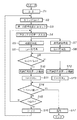
上記を実現するため、符号化シーケンス制御部110は図3のフローチャートに従って処理を行えば良い。
In order to realize the above, the encoding
先ず、ステップS1で変数iに初期値として0をセットする。次いで、ステップS2では、第1のカウンタ111に相当する変数Cnをゼロクリアする。
First, in step S1, 0 is set as an initial value for the variable i. Next, in step S2, the variable Cn corresponding to the
このあと、ステップS3で第1の符号化部102に量子化マトリクステーブルQiをセットし、ステップS4で1画素ブロックのデータを入力する。そして、ステップS5にて第2の符号化部103で可逆符号化を行い、ステップS6にてその際に得られた符号化データ長Lxを求める。また、これと並行して、ステップS7、8では、非可逆符号化を行わせ、その際に得られる符号化データの符号化長Lyを求める。
Thereafter, in step S3, the quantization matrix table Qi is set in the
なお、図示ではステップS5、6とステップS7、8は並行して行う例を示しているが、コンピュータプログラムで実現する場合であって、且つ、マルチタスクOSが稼働するのであれば同様に処理できる。また、シングルタスクOSで実現する場合には、ステップS5、6、7、8の順に処理すれば良いであろう。 In the figure, steps S5 and S6 and steps S7 and S8 are performed in parallel. However, the processing can be similarly performed if the processing is realized by a computer program and the multitask OS is operated. . Further, in the case of realizing with a single task OS, the processing may be performed in the order of steps S5, 6, 7, and 8.
ステップS9では、Ly≧fi(Lx)を満たすか否かを判定する。この関係を満たす場合には、ステップS10にて第1のメモリには可逆符号化データを格納させる。そして、ステップS11にて、カウンタCnに符号長Lxを加算する。 In step S9, it determines whether or not satisfy Ly ≧ f i (Lx). If this relationship is satisfied, lossless encoded data is stored in the first memory in step S10. In step S11, the code length Lx is added to the counter Cn.
一方、ステップS9にてLy<fi(Lx)であると判定した場合には、ステップS12にて、第1のメモリには非可逆符号化データを格納させる。そして、ステップS13にて、カウンタCnに符号長Lyを加算する。 On the other hand, if it is determined in step S9 that Ly <f i (Lx), lossy encoded data is stored in the first memory in step S12. In step S13, the code length Ly is added to the counter Cn.
次に、ステップS14に進んで1ページの符号化処理が終了したか否かを判定する。この判定は、入力した画素ブロック数が、1ページの総画素ブロック数になったか否かで判定すれば良い。 Next, the process proceeds to step S14 to determine whether or not the encoding process for one page has been completed. This determination may be made based on whether or not the number of input pixel blocks has reached the total number of pixel blocks in one page.
このステップS14で未終了と判定した場合には、ステップS15に進み、カウンタCnの値が目標データ量を示す閾値T以上になったか否かをい判定する。否の場合には、次の画素ブロックを入力するため、ステップS4に戻る。 If it is determined in step S14 that the process has not been completed, the process proceeds to step S15, where it is determined whether or not the value of the counter Cn is equal to or greater than a threshold value T indicating the target data amount. If not, the process returns to step S4 to input the next pixel block.
また、カウンタCnが閾値T以上になったと判定した場合、ステップS16に進み、変数iを“1”だけ増加させ、画像をページの先頭から再度入力するため、ステップS2に戻る。 If it is determined that the counter Cn is equal to or greater than the threshold value T, the process proceeds to step S16, the variable i is incremented by “1”, and the image is input again from the top of the page, so the process returns to step S2.
一方、ステップS14にて1ページ分の符号化処理が完了したと判定した場合には、ステップS17に進み、第1のメモリ105に格納された符号化データを2次記憶装置7に出力する処理を行う。
On the other hand, if it is determined in step S14 that the encoding process for one page has been completed, the process proceeds to step S17, and the encoded data stored in the
以上説明したように本実施形態によれば、格別な像域判定回路を設けることなく、可逆符号化、非可逆符号化を併用しつつ像域毎に適切な符号化処理を実行するのと等価の符号化データを生成することが可能になる。また、目標符号化データを超えた場合には、量子化マトリクステーブルを変更し、画像データの再入力・再符号化を行うことで、目標データ量以下の符号化データを生成することも成功する。 As described above, according to the present embodiment, it is equivalent to performing appropriate encoding processing for each image area while using both lossless encoding and lossy encoding without providing a special image area determination circuit. It is possible to generate the encoded data. In addition, when the target encoded data is exceeded, the quantization matrix table is changed, and re-input / re-encoding of the image data is performed, so that it is possible to successfully generate encoded data equal to or less than the target data amount. .
<第2の実施形態の説明>
上記実施形態(第1の実施形態)では、1ページの符号化を行っている最中に、生成される符号化データ量が目標データ量を超えると、再度入力するものであった。
<Description of Second Embodiment>
In the above embodiment (first embodiment), if the amount of encoded data to be generated exceeds the target data amount during the encoding of one page, the input is performed again.
本第2の実施形態では、1ページの画像の再入力を行うことなく、目標データ量以下の符号化データを生成する例を説明する。 In the second embodiment, an example will be described in which encoded data equal to or less than the target data amount is generated without re-inputting an image of one page.
装置構成は図22と同様であるものとし、以下では符号化処理部6に着目して説明することとする。 The apparatus configuration is assumed to be the same as that shown in FIG.
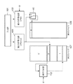
図4は、第2の実施形態における符号化処理部6のブロック構成図である。図1と異なる点は、第2のメモリ制御部106、第2のメモリ107、再符号化部112、並びに第2のカウンタ113が追加された点である。それ以外は図1と同じであるので、同符号を付した。
FIG. 4 is a block configuration diagram of the
また、第1のメモリ105には、先に説明した第1の実施形態と同様の判断基準に従って選択された符号化データが格納されるので、その説明は省略する。従って以下では、本第2の実施形態の特徴的な点について説明することとする。
The
第2のメモリ制御部106は符号化シーケンス制御部110の制御の元で、第2符号化部103で生成された符号化データの第2のメモリ107への格納処理、及び、第2のメモリ107より符号化データの読出しを行う。この第2のメモリ107は、1ページの画像データを符号化する際の作業エリアとして使用されるものである。
The second
再符号化部112は、第2のメモリ107に格納された符号化データ(可逆符号化データ)中の、符号化シーケンス部110より指定された範囲の符号化データを再符号化する。この再符号化部112は例えば図13の構成になる。
The
第2のメモリ107には第2の符号化部(JPEG−LS符号化部)103で符号化された可逆符号化データが格納されているので、先ず、JPEG−LS復号部112aで原画像の画素ブロックに復号(復元)する。そして、JPEG符号化部112bは、復元された画素ブロックを、符号化シーケンス制御部110より設定された量子化マトリクステーブルQiに従ってJPEG符号化(非可逆符号化)を行う。このとき、符号化データの先頭に可逆符号化データであることを示す識別ビットを付加する。
Since the
符号長検出部112cはJPEG符号化された符号化データの符号長を検出し、符号長検出部112dは第2のメモリより読み出した可逆符号化データの符号長を検出する。LUT112eは、符号化シーケンス制御部110内のLUT120と同じ情報を格納しており、符号化シーケンス制御部110からの量子化マトリクステーブル番号iと、2つの符号長データをアドレスとして入力し、1ビットの信号を選択信号として出力する。
The code
セレクタ112fはLUT112eからの選択信号に従って可逆符号化データ、非可逆符号化データのいずれか一方を選択し第2のメモリ制御部106に出力することで、選択した符号化データを第2のメモリ107に格納させる。もう1つのセレクタ112gは選択された符号化データの符号長を選択し、第3のカウンタ113に累積加算させる。
The
上記処理を、符号化シーケンス制御部106より指定された範囲について繰り返し実行する。第2のカウンタ113は、再符号化部112の再符号化が開始される際にリセットされ、再符号化部112で生成される符号化データ量を累積カウントする。設定された範囲の再符号化が完了した場合、第2のカウンタに保持されている値(再符号化で生成された符号化データ量)は、符号化シーケンス制御部110に出力される。
The above process is repeatedly executed for the range specified by the encoding
以上、図4の構成について説明したが、全体の処理を更に詳しく説明すると次の通りである。 The configuration of FIG. 4 has been described above. The overall processing will be described in more detail as follows.
1ページの画像データの符号化を開始する際に、入力される画像サイズに応じた目標データ量が符号化制御部110に制御部1より設定される。符号化シーケンス制御部111は第1の符号化部102に対して初期の量子化マトリクステーブルQ0(最高画質の符号化パラメータ)を設定し、第1のカウンタ111をゼロクリアする。そして、第1の符号化部102、第2の符号化部103に対して符号化処理を開始させる。以下は、1ページの画像データの入力と符号化処理の説明である。
When encoding one page of image data is started, a target data amount corresponding to the input image size is set by the
第1の符号長検出部108及び第2の符号長検出部109より、同じ画素ブロックに対する符号化データが出力されると共に、第1、第2の符号長検出部108、109でそれぞれの符号長が得られる。符号化シーケンス制御部110は、第1の実施形態と同様、すなわち、図2の構成に従って、いずれか一方の符号化データを選択し、その選択した符号化データの符号長情報を第1のカウンタ111に加算させる。このとき、いずれを選択したのかを示す制御信号を第1のメモリ制御部104に出力する。
The first code
第1のメモリ制御部104には、符号化シーケンス制御部110より上記の制御信号を受け取り、符号長の短いと判定された符号化データを選択し、第1のメモリ105に格納する。
The first
以上の結果、第1のメモリ105には、画像データの各画素ブロックについて符号長の短い符号化データが格納されていく。つまり、第1のメモリ105には、可逆符号化データと非可逆符号化データが混在して格納されていく。一方、第2のメモリ107には可逆符号化データのみが格納されていくことになる。
As a result, the
ここで注意したい点は、第1のカウンタ111には第1のメモリ105に格納される符号化データの総符号量の情報が格納されることである。
It should be noted here that the
ここまでは、第2のメモリ107に可逆符号化データが格納される点を除いて、第1の実施形態と同じである。
Up to this point, the second embodiment is the same as the first embodiment except that the lossless encoded data is stored in the
符号化シーケンス制御部110は、符号化処理が進行中、第1のカウンタ111の値、すなわち、第1のメモリ105に格納される符号化データの総量を監視し、目標データ量を越えた(到達も含む)か否かを判定する。そして、第1のカウンタ111に格納された値(総符号量)が、目標データ量を越えたと判定した場合、符号化シーケンス制御部110は次の処理を行う。
1.第1のメモリ105内の格納済みのデータを廃棄するよう第1のメモリ制御部104に制御信号を出力する。第1のメモリ制御部104は、この制御信号に基づいて、メモリアドレスカウンタをクリアするか、あるいは、符号化データ管理テーブルをクリアすることにより、格納された符号化データを廃棄する。
2.第1のカウンタ111をゼロクリアする(入力部101からの画像の入力は継続している)。
3.第1の符号化部102に対して、今までより高い圧縮率で符号化を行うようにするため、量子化マトリクステーブルを更新する。すなわち、従前にセットされた量子化マトリクステーブルがQiであった場合には、Qi+1をセットする。初期状態ではQ0がセットされていたので、最初に目標量を越えたと判定した場合にはQ1がセットされることになる。
4.第2のカウンタ113をゼロクリアし、再符号化部112に量子化マトリクステーブルQi+1をセットし、第2のメモリ107に格納されている符号化データの再符号化を開始させる。再符号化して得られた符号化データ(可逆・非可逆符号化データが混在している)は、第2のメモリ107に再格納する。なお、第2のメモリ107には、第2の符号化部103からの符号化データも格納されているので、両者は区別して格納される。
5.再符号化が完了した場合、第2のメモリ107に「再」格納された符号化データを、第1のメモリ105に転送すると共に、第2のメモリ107より削除する(符号化部103からの符号化データは削除しない)。そして、第2のカウンタ113の値を読出し、第1のカウンタ111に足し込む。この結果、第1のカウンタ111は再び第1のメモリに格納された符号化データの総量を示すことになる。
While the encoding process is in progress, the encoding
1. A control signal is output to the first
2. The
3. The quantization matrix table is updated so that the
4). The
5). When the re-encoding is completed, the encoded data stored “re” in the
なお、再符号化処理が終了したかどうかは、第2のメモリ制御部106が検出する。すなわち、再符号化処理するために読み出すデータが無くなれば、再符号化処理の終了を符号化シーケンス制御部110に知らせる。実際には、第2のメモリ制御部107の読み出し処理だけでなく、再符号化部111の処理も終了した後に、符号化処理が完了したことになる。
Note that the second
そして1ページの画像の入力と符号化が完了する前に再び総符号化データ量が目標データ値を越えたと判断した場合、上記工程1乃至5を実行する。従って、最終的に、第1のメモリ105には目標データ量以下の符号化データが格納されることになる。
If it is determined that the total encoded data amount has again exceeded the target data value before the input and encoding of the image of one page is completed, the
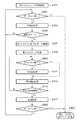
上記、図4の構成における符号化シーケンス制御部110の処理手順を図11のフローチャートに示すが、説明を簡単にするために、簡略化した図5のフローチャートに従ってまず、説明する。
The processing procedure of the encoding
図5のフローチャートは、大別すると、下記の3つの処理フェーズに分かれる。
(1)符号化フェーズ
(2)符号化・再符号化フェーズ
(3)転送フェーズ
上記それぞれの処理フェーズにおいて、どのように画像データ、符号化データ等が流れて処理され、メモリにどのように格納されるのかを視覚的にわかりやすく示したのが図6乃至図10である。
The flowchart of FIG. 5 is roughly divided into the following three processing phases.
(1) Encoding phase (2) Encoding / re-encoding phase (3) Transfer phase In each of the above processing phases, how image data, encoded data, etc. are processed and stored in the memory FIG. 6 to FIG. 10 show how this is done visually.
図6は、図5のフローチャートにおけるステップS303とS305に対応する符号化フェーズの初期状態を表す。なお、図6におけるスイッチ40は、符号化シーケンス制御部110及び第1のメモリ制御部104の機能で実現することになる。切り換えのための信号は、図2に示すLUT120からの信号を利用する。
FIG. 6 shows an initial state of the encoding phase corresponding to steps S303 and S305 in the flowchart of FIG. Note that the
第1のメモリ105には2つの符号化部による符号データのいずれか一方が格納される。従って、第1のメモリ105に格納されるデータ量Iは、第2のメモリ107に格納されるデータ量I’よりも少ない関係が維持されることになる。
The
図7は、ステップS309で量子化マトリクステーブルを変更した際の状態を示している。図示のように、第1のメモリ105内の符号化データはない。
FIG. 7 shows a state when the quantization matrix table is changed in step S309. As shown, there is no encoded data in the
図8は、ステップS311〜S315に対応する符号化・再符号化フェーズの処理状態を示し、図9はステップS317に対応する転送フェーズの処理状態を、図10は転送フェーズ後の符号化フェーズの処理状態を表す。以下、各フェーズについて説明する。 FIG. 8 shows the processing state of the encoding / re-encoding phase corresponding to steps S311 to S315, FIG. 9 shows the processing state of the transfer phase corresponding to step S317, and FIG. 10 shows the encoding phase after the transfer phase. Represents the processing state. Hereinafter, each phase will be described.
<<符号化フェーズ>>
1ページ分の画像データの符号化処理は、符号化パラメータの初期設定処理(ステップS301)から始まる。ここでは、符号化処理する画像サイズ(ページ記述レンダリング等の入力部101から読み取る用紙サイズ)から一意的に定まる符号化データ量の目標データ量や第1の符号化部102に適用する量子化マトリクステーブルQ0を設定する処理である。
<< Encoding Phase >>
The encoding process of image data for one page starts from an encoding parameter initial setting process (step S301). Here, the target data amount of the encoded data amount uniquely determined from the image size to be encoded (paper size read from the
この後、ステップS303にて、第1の符号化部102及び第2の符号化部103にて符号化処理を開始させる。この結果、第1のメモリ105には、画素ブロック単位に、第1の符号化部102からの符号化データと、第2の符号化部103からの符号化データのいずれか一方が格納されていく。第1のメモリ105に格納されている符号化データ量は、第1のカウンタで計数する点は既に述べた通りである。一方、第2のメモリ106には、第2の符号化部103からの符号化データが格納されていくことになる。図6は、この状況を示している。第1のメモリ105に格納されるデータ量を示す領域Iは、少なくとも第2のメモリ107に格納されるデータ量を示す領域I’以下のなる。
Thereafter, in step S303, the
次にステップS305にて、該データ量のカウント値が上記目標値をオーバーしたかどうかを検知し、オーバーしていなければステップS303の第1の符号化と第2の符号化処理を継続する。これが、初期状態の符号化フェーズである。 Next, in step S305, it is detected whether the count value of the data amount has exceeded the target value. If not, the first encoding process and the second encoding process in step S303 are continued. This is the initial encoding phase.
<<符号化・再符号化フェーズ>>
符号化処理が進行し、第1のメモリに格納される総符号データ量が目標量をオーバーすると、ステップS307にて第1のメモリ105内の符号化データを廃棄すると共に、ステップS309にて、第1の符号化部102に設定されていた量子化マトリクステーブルQ0を、次の段階のQ1に更新する。総符号化データ量が目標データ量をオーバーするということは、圧縮後のデータ量が目標以内に収まらないことを意味する。よって同じ量子化ステップを用いて符号化処理を継続しても意味がないので、前よりも量子化ステップ幅の大きい量子化ステップQ1に変更するわけである。
<< Encoding / Recoding Phase >>
When the encoding process proceeds and the total code data amount stored in the first memory exceeds the target amount, the encoded data in the
量子化ステップを変更した後、ステップS311では、第1の符号化部102と第2の符号化部103の符号化処理を再開する。また、再符号化部112に量子化マトリクステーブルQ1(第1の符号化部にセットした更新後の量子化マトリクステーブルと同じ)をセットし、第2のメモリに格納されている符号化データ量の再符号化を開始しさせ、再符号化結果を再び第2のメモリに格納させる。この状態を示すのが図7である。
After changing the quantization step, the encoding process of the
そして、ステップS315で再符号化の処理が完了するまで待つことになる。 In step S315, the process waits until the re-encoding process is completed.
<転送フェーズ>
ステップS315にて、再符号化が完了したと判断した場合、第1メモリ105及び第2のメモリ107の符号化データの格納状況を示すのが図8である。図示において、領域II、II’は、再符号化処理を行っている最中に、新に入力した画像データに対応する符号化データを示し、領域Iは、領域I’に格納されていた符号化データを再符号化した結果(非可逆符号化データと可逆符号化データが混在している)を示している。
<Transfer phase>
When it is determined in step S315 that the re-encoding is completed, FIG. 8 shows the storage status of the encoded data in the
ステップS317では、図9に示すように、第2のメモリ107に格納された再符号化データ(図示の領域I)を、第1のメモリ105に転送する。この転送が完了すると、第2のメモリ107内の領域Iのデータは破棄(もしくは上書きを許容)する。
In step S317, as shown in FIG. 9, the re-encoded data (area I shown in the figure) stored in the
上記転送フェーズが終了したら、ステップS303,S305の符号化フェーズに戻り、符号化フェーズに戻ることになる。この結果、図10に示すように、新たな入力画像データに対する符号化データIII、III’をそれぞれのメモリへの格納処理を行うことになる。この符号化フェーズは、初期状態の符号化フェーズ(図6)と少し異なり、第1の符号化部102で符号化する際の量子化ステップがQ0からQ1に変更されていると共に、第1のメモリ105に格納される符号化データの順序が、画像入力順にならない点である。それらの違いを無視すれば、転送フェーズ直後の符号化フェーズと初期状態の符号化フェーズは、同じと見なせる。なお、図10に示すように、符号化データの順番は必ずしも時系列になるとは限らないが、各フェーズにおける各脳アドレスを別途記憶しておき、1ページの符号化処理が完了し2次記憶装置7に出力する際には、第1のメモリ105より時系列に符号化データを読出し、出力するようにすれば良い。
When the transfer phase ends, the process returns to the encoding phase of steps S303 and S305, and returns to the encoding phase. As a result, as shown in FIG. 10, the encoded data III and III 'for the new input image data are stored in the respective memories. This encoding phase is slightly different from the encoding phase in the initial state (FIG. 6), the quantization step when encoding by the
よって、符号化フェーズ、符号化・再符号化フェーズと転送フェーズの3つを繰り返すことで、最終的に1ページの画像データをデータ量設定値以下に圧縮した符号を第1のメモリ105に格納することが出来る。しかも、入力部101は一連の処理が終わるまで、入力を継続するだけである。すなわち、画像を再度最初から入力し直すということが無くなる。
Therefore, by repeating the encoding phase, the encoding / re-encoding phase, and the transfer phase, the code that finally compresses the image data of one page to the data amount setting value or less is stored in the
図5に示したフローチャートは、説明が理解しやすいように、図6乃至図10に示した各フェーズに対応する処理のみを記述した。しかしながら実際には、1ページの画像データの入力はどこかのフェーズで終了する。従って、どのフェーズで終了したかによって、それ以降の対応も多少異なる。それを考慮した流れを示したのが図11のフローチャートである。図11のフローチャートは、1ページ分の画像データの入力完了と図5で説明した各種処理との関係を考慮したものであり、ここでは図5のフローチャートに、ステップS801、S803、S805、S807を追加している。 The flowchart shown in FIG. 5 describes only the processing corresponding to each phase shown in FIGS. 6 to 10 so that the explanation can be easily understood. In practice, however, the input of image data for one page ends in some phase. Therefore, the correspondence after that is slightly different depending on which phase it is completed. FIG. 11 is a flowchart showing the flow considering this. The flowchart in FIG. 11 considers the relationship between the completion of input of image data for one page and the various processes described with reference to FIG. 5. Here, steps S801, S803, S805, and S807 are added to the flowchart in FIG. It has been added.
ステップS801、S803、S805は、それぞれ、符号化フェーズ、符号化・再符号化フェーズ、転送フェーズにおいて、入力部101からの1ページ分の画像データの入力が終了したことを検知する。
Steps S801, S803, and S805 detect that the input of image data for one page from the
符号化フェーズと転送フェーズで1ページ分の画像データの入力が終了したことを検知した場合(ステップS801、S805)、ステップS807へ移り、当該ページの圧縮符号化処理を終了し、次に処理すべき1ページ以上の画像データがあれば、次の1ページ分の画像データの圧縮符号化処理を開始し、無ければ停止状態に入る。 If it is detected that the input of image data for one page has been completed in the encoding phase and the transfer phase (steps S801 and S805), the process proceeds to step S807, where the compression encoding process for the page is ended, and the next process is performed. If there is more than one page of image data, the compression encoding process of the next one page of image data is started, and if there is no image data, a stop state is entered.
一方、符号化・再符号化フェーズで1ページ分の画像データの入力終了を検知した場合(ステップS803)には、第1の符号化部102、第2の符号化部103では再符号化処理する画像データが無くなるまで一旦動作を止める必要があるので、ステップS311の符号化処理をパスし、ステップS313で、今までに第1の符号化部102、第2の符号化部103で符号化済みの画像データを所定の符号化データ量に抑える為の再符号化処理のみを継続して行なう。再符号化処理が全て終了して、その後の転送処理が終わらないと、1ページ分の画像データ全体の符号化データが第1のメモリ上に集まらないため、1ページ分の画像データの入力終了後も再符号化処理及びそれに続く転送処理は継続して行われる必要がある。この場合には、ステップS315にて、再符号化処理が全て終了したことを検知すると、符号化・再符号化フェーズ中に、第2のメモリ107のみに格納された符号化データを第1のメモリに転送し(ステップS317)た後、次のステップS805にて、1ページ分の画像データの入力終了が検知されてステップS807へ移ることになる。
On the other hand, when the input end of image data for one page is detected in the encoding / re-encoding phase (step S803), the
以上が実施形態における動作であり、図11の動作説明でもある。 The above is the operation in the embodiment, and is also the operation description of FIG.
以上説明したように、本第2の実施形態によれば、第1の実施形態と同様の作用効果を奏することが可能になる。そして、更に、1ページの画像を入力を中断することなく、且つ、再入力を行うことなく、目標符号化データ量以下の符号化データを生成することも可能になる。 As described above, according to the second embodiment, it is possible to achieve the same functions and effects as those of the first embodiment. Further, it is possible to generate encoded data equal to or less than the target encoded data amount without interrupting and re-inputting an image of one page.
特に、注目したい点は、非可逆符号化にJPEG、可逆符号化にJPEG−LSという2つの技術を併用している点である。既に説明したように、JPEG符号化は自然画に対して圧縮効率が高く、JPEG−LS符号化は、文字線画に対して高い圧縮率が得られるし、可逆符号化であるため原画像を忠実に再現することが可能である。 Of particular note is the use of two techniques, JPEG for lossy encoding and JPEG-LS for lossless encoding. As described above, JPEG encoding has high compression efficiency for natural images, and JPEG-LS encoding can obtain a high compression rate for character / line images, and it is lossless encoding, so the original image is faithfully reproduced. Can be reproduced.
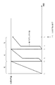
ここで、第1カウンタ111(符号量)の時間軸の推移の一例を図12に示す。 Here, FIG. 12 shows an example of the transition of the time axis of the first counter 111 (code amount).
図示の場合、タイミングT0で、原稿画像の入力を開始し、タイミングT5で原稿画像の入力が完了した場合を示している。入力される原稿のサイズが固定であれば、タイミングT5は固定となる。以下、各タイミングでの処理を説明する。 In the illustrated case, input of a document image is started at timing T0, and input of the document image is completed at timing T5. If the size of the input document is fixed, the timing T5 is fixed. Hereinafter, processing at each timing will be described.
タイミングT0:
画像入力開始(符号化開始)タイミングである。このとき、第1の符号化部102には、初期値として量子化マトリクステーブルQ0をセットし、第1カウンタ111は“0”に初期化される。この後、画像の入力及び符号化が継続すると、画像データの符号化データの符号化が行われ、第1カウンタ111のカウント値は徐々に増えていく。
Timing T0:
This is the image input start (encoding start) timing. At this time, the quantization matrix table Q0 is set as an initial value in the
タイミングT1:
画像データの符号化データ量が、目標符号量に到達した場合を示している。このとき、第1のメモリ105の画像データの符号化データは破棄し、第1カウンタ111をゼロクリアし、第1の符号化部102にセットされていた量子化マトリクステーブルをQ1に更新する。また、再符号化部112にも量子化マトリクステーブルQ1をセットし、再符号化処理を開始させる。
Timing T1:
This shows a case where the encoded data amount of the image data has reached the target code amount. At this time, the encoded data of the image data in the
タイミングT2:
再符号化及び転送処理の完了を示している。再符号化が完了すると、再符号化して得られた符号データが第2のメモリ107から第1のメモリ105に転送されると共に、再符号化データ量を示す第2のカウンタ113の値が、第1のカウンタ111に足し込まれる。この結果、第1のメモリ105及び第2のメモリ107には、1ページの先頭からタイミングT2までの間に入力した画像データに対する量子化マトリクステーブルQ1で符号化したのと等価の符号化データが格納される。
Timing T2:
It shows the completion of the re-encoding and transfer process. When the re-encoding is completed, the code data obtained by re-encoding is transferred from the
タイミングT3:
再び、画像データの符号化データ量が、目標符号量に到達した場合を示している。このとき、第1のメモリ105の画像データの符号化データは破棄し、第1カウンタ111をゼロクリアし、第1の符号化部102の量子化マトリクステーブルをQ2をセットする。また、再符号化部112にも量子化マトリクステーブルQ2をセットし、再符号化処理を開始させる。
Timing T3:
Again, the case where the encoded data amount of the image data has reached the target code amount is shown. At this time, the encoded data of the image data in the
タイミングT4:
再符号化及び転送処理の完了を示している。再符号化が完了すると、再符号化して得られた符号データが第2のメモリ107から第1のメモリ105に転送されると共に、再符号化データ量を示す第2のカウンタ113の値が、第1のカウンタ111に足し込まれる。この結果、第1のメモリ105及び第2のメモリ107には、1ページの先頭からタイミングT2までの間に入力した画像データに対する量子化マトリクステーブルQ2で符号化したのと等価の符号化データが格納される。
Timing T4:
It shows the completion of the re-encoding and transfer process. When the re-encoding is completed, the code data obtained by re-encoding is transferred from the
タイミングT5:
1ページの原稿入力の完了を示している。この場合、第1のメモリ105には、1ページの画像の符号化データが格納されていることになるので、その結果を、2次記憶装置7に出力する。
Timing T5:
This shows the completion of one page of document input. In this case, since the encoded data of the image of one page is stored in the
ここで、2枚めの原稿画像を読取る場合には、上記タイミングT1からの処理を繰り返すことになる。 Here, when the second original image is read, the processing from the timing T1 is repeated.
なお、画像によっては、原稿画像の入力が完了したタイミングT5の直前にて、第1カウンタ111の値が目標量をオーバーすることも有り得る。この場合、タイミングT5の後に、再符号化及び転送処理が行われることになる。従って、第1のメモリ105に格納された符号化データを2次記憶装置7に出力する条件は、原稿画像の入力が完了し、且つ、符号化(再符号化及び転送)が完了した場合となる。
Depending on the image, the value of the
<第2の実施形態の変形例1>
図14は、図4に対する変形例である。図4と異なる点は、再符号化部112で再符号化して得られた符号化データの格納先を、第1のメモリ105にした点である。これ以外の構成は図4と同じである。
<Modification Example 1 of Second Embodiment>
FIG. 14 is a modification to FIG. The difference from FIG. 4 is that the storage location of encoded data obtained by re-encoding by the
図15は、第1のメモリ105に格納された総符号化データ量が目標データをオーバーし、第1のメモリ105内のデータを破棄し、第2のメモリ107に格納されている符号化データ(図示の領域I’)の再符号化を開始する際の状態を示している。
FIG. 15 shows that the total encoded data amount stored in the
図示に示すように、再符号化部112の再符号化の格納先は第1のメモリ105に設定して、再符号化を開始させる。
As shown in the drawing, the re-encoding storage destination of the
図16は、再符号化が完了した際の2つのメモリの符号化データの格納状態を示している。再符号化が完了すると、図示のように、第1のメモリ105には、領域Iで示す符号化データが格納される。この領域Iの符号化データは、目標データ量をオーバーしたと判定する以前までに入力した画像データを、量子化マトリクステーブルQ1で符号化した場合に相当するものとなる。
FIG. 16 shows the storage state of the encoded data in the two memories when the re-encoding is completed. When the re-encoding is completed, the encoded data indicated by the region I is stored in the
再符号化が行われている最中にも、画像データの入力及び符号化が行われているので、図示に示すように領域II及びII’が存在する。 Since image data is being input and encoded while re-encoding is being performed, regions II and II 'exist as shown in the figure.
第1のメモリ105には、空き領域105aが生成されることになるので、図示の領域IIの符号化データを、領域Iの後端位置にまで移動させる。この後、符号化フェーズを再開することになり、この際のメモリへの格納状態は図17に示すようになる。
Since the
図4に対して図14の構成のメリットは、再符号化後のデータ転送が実質的に無くなる点である。 The advantage of the configuration of FIG. 14 compared to FIG. 4 is that data transfer after re-encoding is substantially eliminated.
なお、この変形例では、転送フェーズが無くなるだけであるので、先の第2の実施形態と本変形例は、3つのフェーズを繰り返して処理することに変わりは無い。従って、処理の内容も図5や図11と殆ど同じであるので、説明は不要であろう。なお、図16では空き領域105aを無くすために、第1のメモリ105内での移動を行ったが、各領域の接続関係を管理するファイル管理テーブル、或いは、パケット管理テーブル等を設ければ良いので、必ずしも内部転送は必要ではない。
In this modification, only the transfer phase is eliminated. Therefore, the second embodiment and this modification are processed by repeating three phases. Therefore, the contents of the processing are almost the same as those shown in FIGS. 5 and 11 and need not be described. In FIG. 16, the movement within the
<第2の実施形態の変形例2>
上記第2の実施形態及びその変形例1では、第1のメモリ105内の符号化データ量が目標データ量をオーバーした際に、第2のメモリ107の符号化データを再符号化部112で再符号化した。換言すれば、再符号化部112は、第1のメモリ105内の符号化データ量が目標データ量未満である期間は実行しないことになる。
<
In the second embodiment and the first modification thereof, when the amount of encoded data in the
そこで、期間を有効利用する例を変形例2として説明する。 Therefore, an example in which the period is effectively used will be described as a second modification.
以下は、第1のメモリ105内の符号化データ量が目標データ量未満の場合であって、第2のメモリ107に第2の符号化部103からの可逆符号化データが格納されていく最中の処理の説明である点に注意されたい。また、条件として、第1の符号化部102に設定される量子化マトリクステーブルがQiであるものとして説明する。
The following is a case where the amount of encoded data in the
第2のメモリ107に第2の符号化部103より可逆符号化データを格納していくのは、第2の実施形態と同じである。但し、再符号化部112は、格納されている可逆符号化データから順に読出し、量子化マトリクスQi+1で再符号化して非可逆符号化データを生成し、その結果を第2のメモリ107に格納していく処理を前倒し的に行う。
The lossless encoded data is stored in the
この結果、第1のメモリ105内の符号化データが目標データ量をオーバーしたとき、第2のメモリ107には可逆符号化データは勿論のこと、ある程度の非可逆符号化データが存在することが約束されるので、同一画素ブロック位置であれば小さいほうを第1のメモリに転送し、比べる対象となる非可逆符号化データが存在しない画素ブロックについてだけ、図13による処理を行えば良いことになる。
As a result, when the encoded data in the
また、第2のメモリ107から第1のメモリ105への転送が完了した場合、第2のメモリ内に格納されていた非可逆符号化データを破棄し、今度は、量子化マトリクスQi+2を設定し、再符号化することを開始すればよい。以上の結果、再符号化に係る処理を更に短縮させることが可能になる。
When the transfer from the
以上、本発明に係る第1、第2の実施形態並びにその変形例を説明した。また、第2の実施形態では、第1のメモリ105、第2のメモリ107は物理的に別のメモリであるとして説明をしてきた。本発明においてはこれらのメモリを独立して設けることは十分に1つの特徴となる。しかしながら、これらのメモリを物理的に別のメモリとしない場合も本発明の範疇に含まれる。特に、メモリの転送スピードが、十分に高速な場合には物理的に1つのメモリ上に、第1のメモリ、第2のメモリに相当する2つの領域を確保して、第1のメモリを第1のメモリ領域、第2のメモリを第2のメモリ領域と言い直して、これまでの説明を読み直せば、1つのメモリでも実現できることが分かる。
Heretofore, the first and second embodiments and the modifications thereof according to the present invention have been described. In the second embodiment, the
また、1つのメモリで上記各実施形態を実現する場合には、前記転送フェーズで説明したデータ転送処理のいくつかは不要となる。その詳細はその都度容易に想像できるので説明は省略するが、前記2つの領域を厳密に別けて使用する場合、物理的に2つのメモリを持つ時と同じようにデータ転送処理が必要であるが、2つの領域間で同じデータを共有することになれば、データ転送処理が不要になるだけでなく記憶容量の削減も図れる。 Further, when the above embodiments are realized with one memory, some of the data transfer processes described in the transfer phase are not necessary. The details can be easily imagined each time, so the explanation will be omitted. However, when the two areas are used strictly separated, data transfer processing is necessary as in the case of physically having two memories. If the same data is shared between the two areas, not only the data transfer process becomes unnecessary, but also the storage capacity can be reduced.
例えば、第2のメモリ領域で保持していた符号化データを、第1のメモリ領域へ転送する際、該符号化データが格納されている先頭アドレスとデータサイズの2つの情報を第2のメモリ制御部から第1のメモリ制御部へ転送するだけで、前記符号化データを転送したのと同じ効果が得られる。 For example, when the encoded data held in the second memory area is transferred to the first memory area, two pieces of information of the head address and the data size in which the encoded data is stored are stored in the second memory. The same effect as that obtained by transferring the encoded data can be obtained only by transferring the data from the control unit to the first memory control unit.
前記符号化データを、ファイル形式やパケット形式で格納している場合は、メモリ制御部の間で転送する情報は少し増え、該符号化データに関連する管理テーブル情報を転送する必要がある。 When the encoded data is stored in a file format or a packet format, the information transferred between the memory control units is slightly increased, and it is necessary to transfer the management table information related to the encoded data.
なお、実施形態では、符号化対象を8×8画素ブロックサイズとして説明したが、このサイズも本発明を限定するものではない。要するに、2つ(或いはそれ以上でも良い)の異なる符号化技術を使って、同一の画像領域に対して生成された2種類の符号化データ量を比較できるようにすれば良い。例えば、JPEG符号化ではN×M画素ブロック単位に符号化を行い、JPEG−LSが2N×2Mの画素ブロックを符号化対象とし得るのであれば、4つのJPEG符号化データと1つのJPEG−LS符号化データを比較するようにしても構わない。 In the embodiment, the encoding target has been described as an 8 × 8 pixel block size, but this size is not intended to limit the present invention. In short, it is only necessary to compare two types of encoded data amounts generated for the same image area by using two (or more) different encoding techniques. For example, in JPEG encoding, if encoding is performed in units of N × M pixel blocks, and JPEG-LS can target 2N × 2M pixel blocks, four JPEG encoded data and one JPEG-LS The encoded data may be compared.
また、実施形態では、2種類の符号化技術として、非可逆符号化であるJPEG、可逆符号化であるJPEG−LSを用いる例を説明した。しかしながら、可逆、非可逆符号化技術としては、これによって限定されない。 In the embodiment, an example has been described in which JPEG that is lossy encoding and JPEG-LS that is lossless encoding are used as the two types of encoding techniques. However, the lossless and lossy encoding techniques are not limited to this.
ただし、JPEGとJPEG−LSの様に、非可逆符号化/可逆符号化、及び、自然画/文字線画の両方に対して相異なる性質を持つ2つの符号化技術を用いると、本願発明は有利に作用することがわかるであろう。 However, the present invention is advantageous when two encoding technologies having different properties for both lossy encoding / lossless encoding and natural / character / line drawing are used, such as JPEG and JPEG-LS. You will see that it works.
また、上記第1、第2の実施形態では、図22に示す複写機に適用した例を説明したが、例えばパーソナルコンピュータ等の汎用情報処理装置にイメージスキャナ等の画像入力装置を接続して符号化する場合にも適用できるのは明らかである。この場合、図3、図5(又は図11)に係るプログラムを実行すれば良いので、本願発明はかかるコンピュータプログラムをもその範疇とするのは明らかである。また、通常、コンピュータプログラムはCDROM等のコンピュータ可読記憶媒体をそのコンピュータにセットし、システムにコピーもしくはインストールすることで実行可能になるわけであるから、当然、そのようなコンピュータ可読記憶媒体も本発明の範疇に含まれる。 In the first and second embodiments, the example applied to the copying machine shown in FIG. 22 has been described. For example, an image input device such as an image scanner is connected to a general-purpose information processing device such as a personal computer. It is clear that the present invention can be applied to the case. In this case, since the program according to FIGS. 3 and 5 (or FIG. 11) may be executed, it is clear that the present invention includes such a computer program as its category. In general, a computer program can be executed by setting a computer-readable storage medium such as a CDROM in the computer and copying or installing the computer program in the system. Of course, such a computer-readable storage medium is also included in the present invention. Included in the category.
Claims (10)
符号化対象の画像データから、複数画素で構成される画像ブロックデータを単位に入力する入力手段と、
入力した画像ブロックデータを非可逆符号化し、非可逆の符号化データを生成する第1の符号化手段と、
入力した前記画像ブロックデータを可逆符号化し、可逆の符号化データを生成する第2の符号化手段と、
前記第2の符号化手段で生成された符号化データの符号長をLx、前記第1の符号化手段で生成された符号化データの符号長をLyとし、所定の非線形境界関数f()関数に対し、
条件: Ly≧f(Lx)
を満たす場合に、前記第2の符号化手段で生成された符号化データを選択して出力し、前記非線形境界関数の前記条件を満たさない場合には第1の符号化手段で生成された符号化データを選択して出力する選択手段とを備え、
X軸を前記第2符号化手段で生成される符号化データの符号長、Y軸を前記第1の符号化手段で生成される符号化データの符号長とするX−Y座標空間において、
予め用意された文字線画、自然画、及び、濃度のグラデーションを持つ画像の3つ種類の画像を、前記第1,第2の符号化手段で符号化して得られたそれぞれの画素ブロックデータの符号化データの符号長Ly、Lxで特定される座標(Lx,Ly)を前記X−Y座標空間にプロットした場合の前記文字線画、自然画、及び、濃度のグラデーションを持つ画像のプロット領域をT,I,Gと定義したとき、
前記非線形境界関数f()は、前記X−Y座標の原点を通り、プロット領域Gとプロット領域Iの間を通る曲線部と、プロット領域Tとプロット領域Iとを間を通る線形部を有する
ことを特徴とする画像符号化装置。 An image encoding device for sign-the image data,
Input means for inputting image block data composed of a plurality of pixels in units of image data to be encoded;
Lossy encoding the input image block data, a first encoding means for producing a lossy encoded data,
And lossless encoding said image block data input, a second encoding means for generating a lossless encoded data,
The code length of the encoded data generated by the second encoding means is Lx, the code length of the encoded data generated by the first encoding means is Ly, and a predetermined nonlinear boundary function f () function Whereas
Condition: Ly ≧ f (Lx)
If the condition is satisfied, the encoded data generated by the second encoding unit is selected and output. If the condition of the nonlinear boundary function is not satisfied, the code generated by the first encoding unit is selected. Selecting means for selecting and outputting the digitized data,
In the XY coordinate space where the X axis is the code length of the encoded data generated by the second encoding means, and the Y axis is the code length of the encoded data generated by the first encoding means,
Codes of respective pixel block data obtained by encoding the three types of images prepared in advance by the first and second encoding means: a character line image, a natural image, and an image having a gradation of density. A plot area of the character line image, natural image, and image having a gradation of density when the coordinates (Lx, Ly) specified by the code lengths Ly and Lx of the digitized data are plotted in the XY coordinate space is represented by T , I, and G,
The nonlinear boundary function f () has a curved portion passing through the origin of the XY coordinates, passing between the plot region G and the plot region I, and a linear portion passing between the plot region T and the plot region I. An image encoding apparatus characterized by that.
前記選択手段で出力された符号化データを記憶する第1の記憶手段と、
該第1の記憶手段に記憶された符号化データ量を監視する監視手段と、
該監視手段で前記符号化データ量が所定データ量以上になったと判断した場合、(a)前記第1の記憶手段内の符号化データを破棄し、(b)前記第1の符号化手段に設定されていた従前の量子化マトリクステーブルQiからQi+1にパラメータを更新する制御手段と
を更に備えることを特徴とする請求項4に記載の画像符号化装置。 Initialization means for setting an initial matrix table Q0 in the first encoding means when starting encoding of one page;
First storage means for storing the encoded data output by the selection means;
Monitoring means for monitoring the amount of encoded data stored in the first storage means;
When the monitoring means determines that the amount of encoded data has exceeded a predetermined data amount, (a) the encoded data in the first storage means is discarded, and (b) the first encoding means 5. The image encoding apparatus according to claim 4, further comprising: a control unit that updates the parameter from the previous quantization matrix table Qi that has been set to Qi + 1.
前記第2の記憶手段内の符号化データを復号し、与えられたパラメータに従って再符号化して非可逆の符号化データを生成すると共に、再符号化後の符号化データと再符号化前の可逆符号化データのいずれか一方を前記非線形境界関数f()に従って選択し、前記第1の記憶手段に格納する再符号化手段とを備え、
前記制御手段は、前記監視手段で第1の記憶手段に格納された符号化データ量が所定データ量以上になったと判断した場合、前記(a)、(b)に加えて、(c)パラメータQiを前記再符号化手段に設定して、前記所定データ量以上になる以前の符号化データを生成させることを特徴とする請求項5に記載の画像符号化装置。 And second storage means for storing the lossless encoded data encoded by the second encoding means;
The encoded data in the second storage means is decoded and re-encoded according to the given parameters to generate lossy encoded data, and the encoded data after re-encoding and the reversible before re-encoding Re-encoding means for selecting any one of the encoded data according to the non-linear boundary function f () and storing it in the first storage means,
When the control unit determines that the amount of encoded data stored in the first storage unit is equal to or greater than a predetermined data amount by the monitoring unit, in addition to (a) and (b), (c) parameter 6. The image encoding apparatus according to claim 5, wherein Qi is set in the re-encoding unit, and encoded data before the predetermined data amount is generated is generated.
符号化対象の画像データから、複数画素で構成される画像ブロックデータを単位に入力する入力工程と、
入力した画像ブロックデータを非可逆符号化し、非可逆の符号化データを生成する第1の符号化工程と、
入力した前記画像ブロックデータを可逆符号化し、可逆の符号化データを生成する第2の符号化工程と、
前記第2の符号化工程で生成された符号化データの符号長をLx、前記第1の符号化工程で生成された符号化データの符号長をLyとし、所定の非線形境界関数f()関数に対し、
条件: Ly≧f(Lx)
を満たす場合に、前記第2の符号化工程で生成された符号化データを選択して出力し、前記非線形境界関数の前記条件を満たさない場合には第1の符号化工程で生成された符号化データを選択して出力する選択工程とを備え、
X軸を前記第2符号化工程で生成される符号化データの符号長、Y軸を前記第1の符号化工程で生成される符号化データの符号長とするX−Y座標空間において、
予め用意された文字線画、自然画、及び、濃度のグラデーションを持つ画像の3つ種類の画像を、前記第1,第2の符号化工程で符号化して得られたそれぞれの画素ブロックデータの符号化データの符号長Ly、Lxで特定される座標(Lx,Ly)を前記X−Y座標空間にプロットした場合の前記文字線画、自然画、及び、濃度のグラデーションを持つ画像のプロット領域をT,I,Gと定義したとき、
前記非線形境界関数f()は、前記X−Y座標の原点を通り、プロット領域Gとプロット領域Iの間を通る曲線部と、プロット領域Tとプロット領域Iとを間を通る線形部を有する
ことを特徴とする画像符号化方法。 An image encoding method for inputting and encoding image data in units of pixel blocks of a predetermined size,
An input step of inputting image block data composed of a plurality of pixels from the image data to be encoded in units;
Lossy encoding the input image block data, a first encoding step of generating the lossy encoded data,
And lossless encoding said image block data input, a second encoding step of generating a lossless encoded data,
The code length Lx of the second encoding step encoded data generated by said first code length of the coded data generated by the encoding process to the Ly, predetermined non-linear boundary function f () function Whereas
Condition: Ly ≧ f (Lx)
If the condition is satisfied, the encoded data generated in the second encoding step is selected and output. If the condition of the nonlinear boundary function is not satisfied, the code generated in the first encoding step is output. And a selection process for selecting and outputting the digitized data,
In the XY coordinate space where the X axis is the code length of the encoded data generated in the second encoding step, and the Y axis is the code length of the encoded data generated in the first encoding step,
Codes of the respective pixel block data obtained by encoding the three types of images prepared in advance in the first and second encoding processes: a character line image, a natural image, and an image having a gradation of density. A plot area of the character line image, natural image, and image having a gradation of density when the coordinates (Lx, Ly) specified by the code lengths Ly and Lx of the digitized data are plotted in the XY coordinate space is represented by T , I, and G,
The nonlinear boundary function f () has a curved portion passing through the origin of the XY coordinates, passing between the plot region G and the plot region I, and a linear portion passing between the plot region T and the plot region I. An image encoding method characterized by the above.
符号化対象の画像データから、複数画素で構成される画像ブロックデータを単位に入力する入力手段と、
入力した画像ブロックデータを非可逆符号化し、非可逆の符号化データを生成する第1の符号化手段と、
入力した前記画像ブロックデータを可逆符号化し、可逆の符号化データを生成する第2の符号化手段と、
前記第2の符号化手段で生成された符号化データの符号長をLx、前記第1の符号化手段で生成された符号化データの符号長をLyとし、所定の非線形境界関数f()関数に対し、
条件: Ly≧f(Lx)
を満たす場合に、前記第2の符号化手段で生成された符号化データを選択して出力し、前記非線形境界関数の前記条件を満たさない場合には第1の符号化手段で生成された符号化データを選択して出力する選択手段として機能させ、
X軸を前記第2符号化手段で生成される符号化データの符号長、Y軸を前記第1の符号化手段で生成される符号化データの符号長とするX−Y座標空間において、
予め用意された文字線画、自然画、及び、濃度のグラデーションを持つ画像の3つ種類の画像を、前記第1,第2の符号化手段で符号化して得られたそれぞれの画素ブロックデータの符号化データの符号長Ly、Lxで特定される座標(Lx,Ly)を前記X−Y座標空間にプロットした場合の前記文字線画、自然画、及び、濃度のグラデーションを持つ画像のプロット領域をT,I,Gと定義したとき、
前記非線形境界関数f()は、前記X−Y座標の原点を通り、プロット領域Gとプロット領域Iの間を通る曲線部と、プロット領域Tとプロット領域Iとを間を通る線形部を有する
ことを特徴とするコンピュータプログラム。 A computer program that causes a computer to function as an image encoding device that inputs and encodes image data in units of pixel blocks of a predetermined size when read and executed by a computer,
Input means for inputting image block data composed of a plurality of pixels in units of image data to be encoded;
Lossy encoding the input image block data, a first encoding means for producing a lossy encoded data,
And lossless encoding said image block data input, a second encoding means for generating a lossless encoded data,
The code length of the encoded data generated by the second encoding means is Lx, the code length of the encoded data generated by the first encoding means is Ly, and a predetermined nonlinear boundary function f () function Whereas
Condition: Ly ≧ f (Lx)
If the condition is satisfied, the encoded data generated by the second encoding unit is selected and output. If the condition of the nonlinear boundary function is not satisfied, the code generated by the first encoding unit is selected. Function as a selection means to select and output data,
In the XY coordinate space where the X axis is the code length of the encoded data generated by the second encoding means, and the Y axis is the code length of the encoded data generated by the first encoding means,
Codes of respective pixel block data obtained by encoding the three types of images prepared in advance by the first and second encoding means: a character line image, a natural image, and an image having a gradation of density. A plot area of the character line image, natural image, and image having a gradation of density when the coordinates (Lx, Ly) specified by the code lengths Ly and Lx of the digitized data are plotted in the XY coordinate space is represented by T , I, and G,
The nonlinear boundary function f () has a curved portion passing through the origin of the XY coordinates, passing between the plot region G and the plot region I, and a linear portion passing between the plot region T and the plot region I. A computer program characterized by the above.
Priority Applications (3)
| Application Number | Priority Date | Filing Date | Title |
|---|---|---|---|
| JP2004261565A JP4393319B2 (en) | 2004-09-08 | 2004-09-08 | Image encoding apparatus and method, computer program, and computer-readable storage medium |
| CNB200510098330XA CN100493133C (en) | 2004-09-08 | 2005-09-07 | Image encoding apparatus and method |
| US11/220,536 US7627181B2 (en) | 2004-09-08 | 2005-09-08 | Image encoding apparatus and method, computer program, and computer-readable storage medium |
Applications Claiming Priority (1)
| Application Number | Priority Date | Filing Date | Title |
|---|---|---|---|
| JP2004261565A JP4393319B2 (en) | 2004-09-08 | 2004-09-08 | Image encoding apparatus and method, computer program, and computer-readable storage medium |
Publications (3)
| Publication Number | Publication Date |
|---|---|
| JP2006080792A JP2006080792A (en) | 2006-03-23 |
| JP2006080792A5 JP2006080792A5 (en) | 2009-09-10 |
| JP4393319B2 true JP4393319B2 (en) | 2010-01-06 |
Family
ID=35996278
Family Applications (1)
| Application Number | Title | Priority Date | Filing Date |
|---|---|---|---|
| JP2004261565A Expired - Fee Related JP4393319B2 (en) | 2004-09-08 | 2004-09-08 | Image encoding apparatus and method, computer program, and computer-readable storage medium |
Country Status (3)
| Country | Link |
|---|---|
| US (1) | US7627181B2 (en) |
| JP (1) | JP4393319B2 (en) |
| CN (1) | CN100493133C (en) |
Families Citing this family (20)
| Publication number | Priority date | Publication date | Assignee | Title |
|---|---|---|---|---|
| JP4693603B2 (en) * | 2004-11-15 | 2011-06-01 | キヤノン株式会社 | Image encoding apparatus, control method therefor, computer program, and computer-readable storage medium |
| US7925098B2 (en) * | 2006-03-02 | 2011-04-12 | Canon Kabushiki Kaisha | Image encoding apparatus and method with both lossy and lossless means |
| JP4795161B2 (en) * | 2006-08-08 | 2011-10-19 | キヤノン株式会社 | Image processing apparatus, control method therefor, computer program, and computer-readable storage medium |
| JP2008042688A (en) * | 2006-08-08 | 2008-02-21 | Canon Inc | Image processing apparatus and control method thereof, and computer program and computer readable storage medium |
| JP4682107B2 (en) * | 2006-08-28 | 2011-05-11 | 株式会社リコー | Image forming apparatus, information processing method, and information processing program |
| JP2008054210A (en) * | 2006-08-28 | 2008-03-06 | Ricoh Co Ltd | Image forming apparatus, information processing method and information processing program |
| US20080212130A1 (en) * | 2007-02-21 | 2008-09-04 | Samsung Electronics Co., Ltd. | Data file compression apparatus and method thereof |
| KR101375662B1 (en) * | 2007-08-06 | 2014-03-18 | 삼성전자주식회사 | Method and apparatus for image data compression |
| US8014612B2 (en) * | 2007-10-12 | 2011-09-06 | Himax Technologies Limited | Image processing device and method for compressing and decompressing images |
| JP5153676B2 (en) * | 2009-02-10 | 2013-02-27 | キヤノン株式会社 | Image processing apparatus, image processing method, program, and storage medium |
| JP5089713B2 (en) * | 2010-01-18 | 2012-12-05 | シャープ株式会社 | Image compression apparatus, compressed image output apparatus, image compression method, computer program, and recording medium |
| CN101783952A (en) * | 2010-03-01 | 2010-07-21 | 广东威创视讯科技股份有限公司 | Coding optimization method and coding optimization device for images |
| EP3462738A1 (en) * | 2011-02-10 | 2019-04-03 | Velos Media International Limited | Efficient signaling of quantization matrices |
| US9185424B2 (en) | 2011-07-05 | 2015-11-10 | Qualcomm Incorporated | Image data compression |
| JP6056124B2 (en) * | 2011-09-05 | 2017-01-11 | 富士ゼロックス株式会社 | Image processing apparatus and image processing program |
| CN103369313B (en) * | 2012-03-31 | 2017-10-10 | 百度在线网络技术(北京)有限公司 | A kind of method, device and equipment for carrying out compression of images |
| CN103543974B (en) * | 2013-07-31 | 2017-03-08 | Tcl集团股份有限公司 | A kind of method and system improving font clarity |
| CN103544931B (en) * | 2013-10-12 | 2017-04-19 | Tcl集团股份有限公司 | Character generating method and device and application terminal |
| CN106778289A (en) | 2015-11-24 | 2017-05-31 | 虹光精密工业(苏州)有限公司 | Information Security Management System and the transaction machine using the system |
| CN108810537B (en) * | 2017-04-26 | 2023-04-07 | 腾讯科技(深圳)有限公司 | Picture transcoding method and device and image processing equipment |
Family Cites Families (64)
| Publication number | Priority date | Publication date | Assignee | Title |
|---|---|---|---|---|
| US5247357A (en) * | 1989-05-31 | 1993-09-21 | Scientific Atlanta, Inc. | Image compression method and apparatus employing distortion adaptive tree search vector quantization with avoidance of transmission of redundant image data |
| JP3171913B2 (en) | 1992-04-03 | 2001-06-04 | キヤノン株式会社 | Image encoding apparatus and image encoding method |
| JPH0651721A (en) | 1992-07-29 | 1994-02-25 | Canon Inc | Display controller |
| JP2800633B2 (en) | 1993-04-30 | 1998-09-21 | 富士ゼロックス株式会社 | Image coding device |
| US5764804A (en) | 1993-10-14 | 1998-06-09 | Seiko Epson Corporation | Data encoding and decoding system |
| JP2720926B2 (en) | 1993-10-26 | 1998-03-04 | 富士ゼロックス株式会社 | Image coding device |
| JPH08130649A (en) | 1994-11-01 | 1996-05-21 | Canon Inc | Data processing unit |
| US6031938A (en) | 1995-04-26 | 2000-02-29 | Canon Kabushiki Kaisha | Image encoding apparatus with selective Markov and predictive coding |
| US6101282A (en) | 1995-06-22 | 2000-08-08 | Canon Kabushiki Kaisha | Apparatus and method for image data encoding |
| DE69623882T2 (en) | 1995-07-17 | 2003-05-08 | Canon K.K., Tokio/Tokyo | Image processing device and method |
| US5960116A (en) | 1995-11-02 | 1999-09-28 | Canon Kabushiki Kaisha | Image processing apparatus and method for performing prediction data encoding |
| US6266449B1 (en) | 1995-11-22 | 2001-07-24 | Canon Kabushiki Kaisha | Information processing apparatus and method which selectively controls data encoding by monitoring amount of encoded data |
| US6094510A (en) | 1996-04-15 | 2000-07-25 | Canon Kabushiki Kaisha | Image processing apparatus and method for predicting a compression rate of image data processed to modify an image |
| US6028963A (en) | 1996-06-17 | 2000-02-22 | Canon Kabushiki Kaisha | Image encoding based on judgement on prediction error |
| JPH104557A (en) | 1996-06-17 | 1998-01-06 | Canon Inc | Unit, and method for image processing and storage medium storing the method |
| JP3787389B2 (en) | 1996-06-17 | 2006-06-21 | キヤノン株式会社 | Image processing apparatus and method, and storage medium storing the method |
| JP3408094B2 (en) | 1997-02-05 | 2003-05-19 | キヤノン株式会社 | Image processing apparatus and method |
| JPH10336682A (en) | 1997-04-02 | 1998-12-18 | Canon Inc | Coder, its method and storage medium storing the method |
| JP3699814B2 (en) | 1997-11-28 | 2005-09-28 | 富士ゼロックス株式会社 | Image processing apparatus and image processing method |
| US6650361B1 (en) * | 1997-12-17 | 2003-11-18 | Canon Kabushiki Kaisha | Imaging apparatus control method, and a computer program product having computer program code therefor |
| US6175650B1 (en) | 1998-01-26 | 2001-01-16 | Xerox Corporation | Adaptive quantization compatible with the JPEG baseline sequential mode |
| JP2000069292A (en) | 1998-08-24 | 2000-03-03 | Canon Inc | Image processing unit, its method and storage medium |
| JP3839974B2 (en) | 1998-10-06 | 2006-11-01 | キヤノン株式会社 | Encoder |
| JP2000115782A (en) | 1998-10-06 | 2000-04-21 | Canon Inc | Coder, coding method and storage medium |
| JP2000115783A (en) | 1998-10-06 | 2000-04-21 | Canon Inc | Decoder and its method |
| US6665444B1 (en) | 1999-04-28 | 2003-12-16 | Canon Kabushiki Kaisha | Image processing apparatus and method, and storage medium |
| JP2001045301A (en) | 1999-08-02 | 2001-02-16 | Fuji Xerox Co Ltd | Image processor |
| JP4365957B2 (en) | 1999-11-05 | 2009-11-18 | キヤノン株式会社 | Image processing method and apparatus and storage medium |
| JP4367880B2 (en) | 1999-12-09 | 2009-11-18 | キヤノン株式会社 | Image processing apparatus and method, and storage medium |
| US6771828B1 (en) * | 2000-03-03 | 2004-08-03 | Microsoft Corporation | System and method for progessively transform coding digital data |
| JP2002281444A (en) | 2000-03-03 | 2002-09-27 | Canon Inc | Method and device for processing image and storage medium |
| JP4208378B2 (en) | 2000-03-10 | 2009-01-14 | キヤノン株式会社 | Image processing apparatus and method, and recording medium |
| JP4480119B2 (en) | 2000-03-30 | 2010-06-16 | キヤノン株式会社 | Image processing apparatus and image processing method |
| US6847735B2 (en) | 2000-06-07 | 2005-01-25 | Canon Kabushiki Kaisha | Image processing system, image processing apparatus, image input apparatus, image output apparatus and method, and storage medium |
| JP4612782B2 (en) | 2000-09-27 | 2011-01-12 | キヤノン株式会社 | Image processing apparatus, method thereof, program, and storage medium |
| US6853755B2 (en) | 2001-03-28 | 2005-02-08 | Sharp Laboratories Of America, Inc. | Method and apparatus for adaptive compression of scanned documents |
| JP4003410B2 (en) | 2001-06-11 | 2007-11-07 | 富士ゼロックス株式会社 | Encoding selection apparatus, encoding apparatus and method thereof |
| EP1271926B1 (en) | 2001-06-18 | 2015-08-12 | Canon Kabushiki Kaisha | Image processing method, apparatus and computer program for compression-encoding |
| JP3984813B2 (en) | 2001-10-12 | 2007-10-03 | キヤノン株式会社 | Image processing apparatus and method, computer program, and storage medium |
| JP4124982B2 (en) | 2001-06-18 | 2008-07-23 | キヤノン株式会社 | Image processing apparatus and method, computer program, and storage medium |
| US7013050B2 (en) | 2001-06-26 | 2006-03-14 | Canon Kabushiki Kaisha | Image encoding apparatus and method, program code, and storage medium |
| US20030031371A1 (en) | 2001-08-02 | 2003-02-13 | Shinichi Kato | Image encoding apparatus and image decoding apparatus |
| CN1320809C (en) | 2001-08-29 | 2007-06-06 | 佳能株式会社 | Picture processing device and method, and computer program and storage medium |
| JP3984886B2 (en) | 2001-09-28 | 2007-10-03 | キヤノン株式会社 | Data conversion apparatus, data conversion method, computer program, and storage medium |
| JP2003143411A (en) | 2001-11-02 | 2003-05-16 | Canon Inc | Picture processing apparatus, control method thereof, computer program, and memorizing medium |
| US7194140B2 (en) | 2001-11-05 | 2007-03-20 | Canon Kabushiki Kaisha | Image processing apparatus and method which compresses image data of each region using a selected encoding method |
| JP3902953B2 (en) | 2002-01-10 | 2007-04-11 | キヤノン株式会社 | Image processing apparatus and method, computer program, and storage medium |
| US7106909B2 (en) | 2001-12-25 | 2006-09-12 | Canon Kabushiki Kaisha | Method and apparatus for encoding image data in accordance with a target data size |
| JP2003244446A (en) | 2002-02-21 | 2003-08-29 | Canon Inc | Image processor and image processing method |
| JP4047183B2 (en) | 2002-03-07 | 2008-02-13 | キヤノン株式会社 | Image compression encoding apparatus and control method thereof |
| JP3902968B2 (en) | 2002-03-26 | 2007-04-11 | キヤノン株式会社 | Image processing apparatus, control method therefor, computer program, and storage medium |
| WO2003084243A1 (en) | 2002-03-28 | 2003-10-09 | Sony Corporation | Image compression/encoding device, method, and program |
| JP2003304404A (en) | 2002-04-09 | 2003-10-24 | Canon Inc | Image encoder |
| JP4065522B2 (en) | 2003-01-07 | 2008-03-26 | キヤノン株式会社 | Image processing apparatus and control method thereof |
| US7227998B2 (en) | 2002-06-11 | 2007-06-05 | Canon Kabushiki Kaisha | Image processing apparatus, control method of the same, computer program, and computer-readable storage medium |
| US7302105B2 (en) | 2002-07-22 | 2007-11-27 | Canon Kabushiki Kaisha | Moving image coding apparatus, moving image decoding apparatus, and methods therefor |
| US7903734B2 (en) | 2003-04-24 | 2011-03-08 | Canon Kabushiki Kaisha | Moving image decoding apparatus, moving image decoding method, image decoding method, and image decoding apparatus |
| US7574063B2 (en) | 2003-07-23 | 2009-08-11 | Canon Kabushiki Kaisha | Image coding method and apparatus |
| JP4418762B2 (en) | 2004-05-07 | 2010-02-24 | キヤノン株式会社 | Image encoding apparatus, image decoding apparatus, control method thereof, computer program, and computer-readable storage medium |
| JP4533035B2 (en) | 2004-08-02 | 2010-08-25 | キヤノン株式会社 | Image encoding apparatus and method, computer program, and computer-readable storage medium |
| JP4533043B2 (en) | 2004-08-25 | 2010-08-25 | キヤノン株式会社 | Image encoding apparatus and method, computer program, and computer-readable storage medium |
| US6987468B1 (en) | 2004-10-29 | 2006-01-17 | Microsoft Corporation | Lossless adaptive encoding and decoding of integer data |
| US7925098B2 (en) | 2006-03-02 | 2011-04-12 | Canon Kabushiki Kaisha | Image encoding apparatus and method with both lossy and lossless means |
| JP2008042688A (en) | 2006-08-08 | 2008-02-21 | Canon Inc | Image processing apparatus and control method thereof, and computer program and computer readable storage medium |
-
2004
- 2004-09-08 JP JP2004261565A patent/JP4393319B2/en not_active Expired - Fee Related
-
2005
- 2005-09-07 CN CNB200510098330XA patent/CN100493133C/en not_active Expired - Fee Related
- 2005-09-08 US US11/220,536 patent/US7627181B2/en not_active Expired - Fee Related
Also Published As
| Publication number | Publication date |
|---|---|
| JP2006080792A (en) | 2006-03-23 |
| CN1747525A (en) | 2006-03-15 |
| US7627181B2 (en) | 2009-12-01 |
| US20060050974A1 (en) | 2006-03-09 |
| CN100493133C (en) | 2009-05-27 |
Similar Documents
| Publication | Publication Date | Title |
|---|---|---|
| JP4533043B2 (en) | Image encoding apparatus and method, computer program, and computer-readable storage medium | |
| JP4393319B2 (en) | Image encoding apparatus and method, computer program, and computer-readable storage medium | |
| JP4693603B2 (en) | Image encoding apparatus, control method therefor, computer program, and computer-readable storage medium | |
| US7454070B2 (en) | Image encoding apparatus and method, computer program, and computer-readable storage medium | |
| US7466863B2 (en) | Image encoding apparatus and method, computer program, computer-readable storage medium, and image forming apparatus | |
| JP3902968B2 (en) | Image processing apparatus, control method therefor, computer program, and storage medium | |
| US7925098B2 (en) | Image encoding apparatus and method with both lossy and lossless means | |
| EP1271926B1 (en) | Image processing method, apparatus and computer program for compression-encoding | |
| US7715637B2 (en) | Image processing apparatus and control method therefor | |
| JP4697967B2 (en) | Image coding apparatus and control method thereof | |
| JPH1051642A (en) | Image processor | |
| JP2008042688A (en) | Image processing apparatus and control method thereof, and computer program and computer readable storage medium | |
| JP2008072624A (en) | Image encoding device and its control method | |
| JP4697966B2 (en) | Image encoding apparatus and method, computer program, and computer-readable storage medium | |
| JP3902953B2 (en) | Image processing apparatus and method, computer program, and storage medium | |
| JP3984813B2 (en) | Image processing apparatus and method, computer program, and storage medium | |
| US6879725B2 (en) | Method, system, and program for decoding a section from compressed data | |
| JP4697965B2 (en) | Image encoding apparatus and method, computer program, and computer-readable storage medium | |
| JP4715175B2 (en) | Image forming apparatus and method | |
| JP4651109B2 (en) | Image encoding apparatus and method, computer program, and computer-readable storage medium | |
| JP2011004284A (en) | Image coding apparatus and method of controlling the same | |
| JP2013121154A (en) | Image processing device |
Legal Events
| Date | Code | Title | Description |
|---|---|---|---|
| A521 | Written amendment |
Free format text: JAPANESE INTERMEDIATE CODE: A523 Effective date: 20070828 |
|
| A621 | Written request for application examination |
Free format text: JAPANESE INTERMEDIATE CODE: A621 Effective date: 20070828 |
|
| RD03 | Notification of appointment of power of attorney |
Free format text: JAPANESE INTERMEDIATE CODE: A7423 Effective date: 20070828 |
|
| A521 | Written amendment |
Free format text: JAPANESE INTERMEDIATE CODE: A523 Effective date: 20090729 |
|
| A977 | Report on retrieval |
Free format text: JAPANESE INTERMEDIATE CODE: A971007 Effective date: 20091005 |
|
| TRDD | Decision of grant or rejection written | ||
| A01 | Written decision to grant a patent or to grant a registration (utility model) |
Free format text: JAPANESE INTERMEDIATE CODE: A01 Effective date: 20091009 |
|
| A01 | Written decision to grant a patent or to grant a registration (utility model) |
Free format text: JAPANESE INTERMEDIATE CODE: A01 |
|
| A61 | First payment of annual fees (during grant procedure) |
Free format text: JAPANESE INTERMEDIATE CODE: A61 Effective date: 20091013 |
|
| R150 | Certificate of patent or registration of utility model |
Ref document number: 4393319 Country of ref document: JP Free format text: JAPANESE INTERMEDIATE CODE: R150 Free format text: JAPANESE INTERMEDIATE CODE: R150 |
|
| FPAY | Renewal fee payment (event date is renewal date of database) |
Free format text: PAYMENT UNTIL: 20121023 Year of fee payment: 3 |
|
| FPAY | Renewal fee payment (event date is renewal date of database) |
Free format text: PAYMENT UNTIL: 20131023 Year of fee payment: 4 |
|
| LAPS | Cancellation because of no payment of annual fees |