JP4047183B2 - Image compression encoding apparatus and control method thereof - Google Patents
Image compression encoding apparatus and control method thereof Download PDFInfo
- Publication number
- JP4047183B2 JP4047183B2 JP2003027607A JP2003027607A JP4047183B2 JP 4047183 B2 JP4047183 B2 JP 4047183B2 JP 2003027607 A JP2003027607 A JP 2003027607A JP 2003027607 A JP2003027607 A JP 2003027607A JP 4047183 B2 JP4047183 B2 JP 4047183B2
- Authority
- JP
- Japan
- Prior art keywords
- encoded data
- data amount
- compression
- unit
- encoding
- Prior art date
- Legal status (The legal status is an assumption and is not a legal conclusion. Google has not performed a legal analysis and makes no representation as to the accuracy of the status listed.)
- Expired - Fee Related
Links
Images


Classifications
-
- H—ELECTRICITY
- H04—ELECTRIC COMMUNICATION TECHNIQUE
- H04N—PICTORIAL COMMUNICATION, e.g. TELEVISION
- H04N19/00—Methods or arrangements for coding, decoding, compressing or decompressing digital video signals
- H04N19/10—Methods or arrangements for coding, decoding, compressing or decompressing digital video signals using adaptive coding
- H04N19/169—Methods or arrangements for coding, decoding, compressing or decompressing digital video signals using adaptive coding characterised by the coding unit, i.e. the structural portion or semantic portion of the video signal being the object or the subject of the adaptive coding
- H04N19/17—Methods or arrangements for coding, decoding, compressing or decompressing digital video signals using adaptive coding characterised by the coding unit, i.e. the structural portion or semantic portion of the video signal being the object or the subject of the adaptive coding the unit being an image region, e.g. an object
-
- H—ELECTRICITY
- H04—ELECTRIC COMMUNICATION TECHNIQUE
- H04N—PICTORIAL COMMUNICATION, e.g. TELEVISION
- H04N19/00—Methods or arrangements for coding, decoding, compressing or decompressing digital video signals
- H04N19/10—Methods or arrangements for coding, decoding, compressing or decompressing digital video signals using adaptive coding
- H04N19/102—Methods or arrangements for coding, decoding, compressing or decompressing digital video signals using adaptive coding characterised by the element, parameter or selection affected or controlled by the adaptive coding
- H04N19/124—Quantisation
-
- H—ELECTRICITY
- H04—ELECTRIC COMMUNICATION TECHNIQUE
- H04N—PICTORIAL COMMUNICATION, e.g. TELEVISION
- H04N19/00—Methods or arrangements for coding, decoding, compressing or decompressing digital video signals
- H04N19/10—Methods or arrangements for coding, decoding, compressing or decompressing digital video signals using adaptive coding
- H04N19/134—Methods or arrangements for coding, decoding, compressing or decompressing digital video signals using adaptive coding characterised by the element, parameter or criterion affecting or controlling the adaptive coding
- H04N19/146—Data rate or code amount at the encoder output
- H04N19/15—Data rate or code amount at the encoder output by monitoring actual compressed data size at the memory before deciding storage at the transmission buffer
-
- H—ELECTRICITY
- H04—ELECTRIC COMMUNICATION TECHNIQUE
- H04N—PICTORIAL COMMUNICATION, e.g. TELEVISION
- H04N19/00—Methods or arrangements for coding, decoding, compressing or decompressing digital video signals
- H04N19/10—Methods or arrangements for coding, decoding, compressing or decompressing digital video signals using adaptive coding
- H04N19/169—Methods or arrangements for coding, decoding, compressing or decompressing digital video signals using adaptive coding characterised by the coding unit, i.e. the structural portion or semantic portion of the video signal being the object or the subject of the adaptive coding
- H04N19/17—Methods or arrangements for coding, decoding, compressing or decompressing digital video signals using adaptive coding characterised by the coding unit, i.e. the structural portion or semantic portion of the video signal being the object or the subject of the adaptive coding the unit being an image region, e.g. an object
- H04N19/172—Methods or arrangements for coding, decoding, compressing or decompressing digital video signals using adaptive coding characterised by the coding unit, i.e. the structural portion or semantic portion of the video signal being the object or the subject of the adaptive coding the unit being an image region, e.g. an object the region being a picture, frame or field
-
- H—ELECTRICITY
- H04—ELECTRIC COMMUNICATION TECHNIQUE
- H04N—PICTORIAL COMMUNICATION, e.g. TELEVISION
- H04N19/00—Methods or arrangements for coding, decoding, compressing or decompressing digital video signals
- H04N19/10—Methods or arrangements for coding, decoding, compressing or decompressing digital video signals using adaptive coding
- H04N19/169—Methods or arrangements for coding, decoding, compressing or decompressing digital video signals using adaptive coding characterised by the coding unit, i.e. the structural portion or semantic portion of the video signal being the object or the subject of the adaptive coding
- H04N19/17—Methods or arrangements for coding, decoding, compressing or decompressing digital video signals using adaptive coding characterised by the coding unit, i.e. the structural portion or semantic portion of the video signal being the object or the subject of the adaptive coding the unit being an image region, e.g. an object
- H04N19/176—Methods or arrangements for coding, decoding, compressing or decompressing digital video signals using adaptive coding characterised by the coding unit, i.e. the structural portion or semantic portion of the video signal being the object or the subject of the adaptive coding the unit being an image region, e.g. an object the region being a block, e.g. a macroblock
-
- H—ELECTRICITY
- H04—ELECTRIC COMMUNICATION TECHNIQUE
- H04N—PICTORIAL COMMUNICATION, e.g. TELEVISION
- H04N19/00—Methods or arrangements for coding, decoding, compressing or decompressing digital video signals
- H04N19/60—Methods or arrangements for coding, decoding, compressing or decompressing digital video signals using transform coding
Landscapes
- Engineering & Computer Science (AREA)
- Multimedia (AREA)
- Signal Processing (AREA)
- Compression Or Coding Systems Of Tv Signals (AREA)
- Compression Of Band Width Or Redundancy In Fax (AREA)
Description
【0001】
【発明の属する技術分野】
本発明は、入力された画像のデータ量を好適に圧縮符号化する画像圧縮符号化装置及びその制御方法に関する。
【0002】
【従来の技術】
現在、多くのディジタルイメージング機器に、静止画像に対する圧縮符号化処理機能が搭載されている。これらのディジタルイメージング機器の代表的なものが、いわゆるディジタルカメラの類である。また、ディジタルカラーコピー機も圧縮符号化処理機能を備えるディジタルイメージング機器の一つである。
【0003】
ディジタルカラーコピー機では、原稿読み取り部から印刷部に対して、読み取られた原稿画像データを転送する際のデータ転送量を軽減する目的で、原稿読み取り部には、読み取られた原稿画像データに対する圧縮符号化処理機能が搭載されている。一方、印刷部には、圧縮符号化された原稿画像データ列に対する伸長復号化処理機能が搭載されている。
【0004】
原稿読み取り部の後段に具備される圧縮符号化処理部によって生成される符号化された原稿画像データ列のデータ量は、圧縮符号化処理される前の原稿画像データ、すなわち読み取られたままの原稿画像データのデータ量に比べて、数分の一から十数分の一程度にまで低減され得る。
【0005】
符号化された原稿画像データ列の圧縮符号化処理される前の原稿画像データに対するデータ量の低減度、すなわち圧縮率の上限値は、符号化歪みが伸長復号化処理によって得られる再構成画像データから容易に視認できない程度の値が、その許容される上限値として設定される。
【0006】
一方、上記圧縮率の許容される下限値は、原稿読み取り部における単位時間当たりに読み込むことができる原稿画像データの最大データ量、及び、原稿読み取り部から印刷部に転送する際の圧縮符号化された原稿画像データ列の最大データ転送量といったような、そのシステムにおける各種システムパラメータによって一意に決定される。
【0007】
このように圧縮率の許容される上限値及び下限値が設定されたとしても、供給されるすべての原稿画像データに対する圧縮率をその範囲内に収めるように圧縮符号化処理を行うことは容易ではない。その理由は、量子化テーブルに代表される符号化パラメータとして同一のものを用いて圧縮符号化処理を行った場合であっても、得られる符号化された原稿画像データ列のデータ量は、原稿画像データ毎に不定であるからである。言い換えるならば、読み取られた原稿画像データは、通常、原稿毎にその圧縮率が変わってしまう。
【0008】
これは、読み取られた原稿画像データ毎に、その画像データが有する情報の空間周波数から見た偏り及びその度合いが異なっており、そのような原稿画像データに対する圧縮符号化処理において、値が0である変換係数に対するランレングス符号化及び可変長符号を用いたエントロピー符号化と言ったような被圧縮符号化画像データが持つ冗長性を、限りなく除去するための様々な手法が採用されているためである。
【0009】
従って、すべての原稿画像データに対する圧縮率をその許容される上限値と下限値の間の範囲に収めるように圧縮符号化処理を施すためには、被圧縮符号化データ、すなわち供給される原稿画像データの各々に対して適用する符号化パラメータを適応的に変える必要がある。
【0010】
一般に、圧縮率が一定になるように圧縮符号化処理を行うためには、いわゆる情報量制御あるいは符号量制御と称される符号化制御を実現しなければならない。上記情報量制御の具体的な実現手法として、大きく分けて、フィードフォワード手法とフィードバック手法の2つの手法が知られている。
【0011】
フィードフォワード手法は、圧縮符号化処理を行う前に被圧縮符号化データとして入力される原画像データから別途ダイナミックレンジ、電力、各種統計情報を算出して、それらの算出値を基に最適な符号化パラメータを予測した後、その得られた符号化パラメータを用いて実際の圧縮符号化処理を行うものである。これに対して、フィードバック手法は、試行となる圧縮符号化処理を行うことによって得られた符号化データ量の実測値から最適な符号化パラメータを予測した後、その得られた符号化パラメータを用いて最終的な圧縮符号化処理を行うものである。
【0012】
これらの2つの手法においては、圧縮符号化処理を試行することによって得られた符号化データ量の実測値から最適な符号化パラメータを予測するフィードバック手法の方が、実際に得られた符号化データ量を直接的に予測値算出に用いているという点で、フィードフォワード手法に比べて、より高い精度で目的とする符号化データ量を生成する符号化パラメータの予測値を得ることができる。しかし、このフィードバック手法には、原理的に、試行される圧縮符号化処理のために費やされる時間的なオーバーヘッドが余計にかかってしまうという欠点がある。
【0013】
これに対して、一つの原画像データに対して目標とする圧縮率の符号化データ列が得られるまで何回も圧縮符号化処理を繰り返した場合であっても、その処理時間の増分が許容できるようなシステム、いわばリアルタイム性や性能が過度に要求されないシステムにおいて有限回繰り返し試行アルゴリズムを適用することも可能である(例えば、特許文献1参照)。
【0014】
しかし、ディジタルカメラやディジタルカラーコピー機器のようなディジタルイメージング機器では、一般的にリアルタイム性及び性能が要求される。したがって、最適な符号化パラメータを予測するための試行となる圧縮符号化処理に費やされる時間的なオーバーヘッドは、限りなく小さく抑えることが課題とされ、さらにその予測精度として十分高いものが要求される。
【0015】
ここで、フィードバック手法を用いた情報量制御における最適な符号化パラメータの予測精度を高めるためには、互いに異なる数多くの符号化パラメータを用いて試行となる圧縮符号化処理を複数回行い、それらの符号化パラメータと実際に得られた符号化データ量の実測値との組み合わせ数を増やすことが効果的であることは容易に考えられる。
【0016】
しかし、その時間的なオーバーヘッドを最小限に抑えるためには、試行となる圧縮符号化処理の際に用いられる符号化パラメータの数と同数の演算回路あるいは処理回路を具備し、それらの回路を並列に動作させて、試行となる圧縮符号化処理を高速に行うような工夫が必要となる。そして、従来からこのような課題を解決するために、いくつかの技術が提案されている。その一例として、並列回路アーキテクチャの公知技術がある(例えば、非特許文献1参照)。
【0017】
例えば、上記非特許文献1では、複数の符号化パラメータとしてN組の量子化テーブルを用いて、N個の量子化回路及びN個の発生符号量測定回路を具備する圧縮符号化装置から得られるN個の符号化データ量から曲線近似を行うことによって、最適な符号化パラメータ、すなわち最適な量子化テーブルを得ることが記載されている。
【0018】
また、同様な構成でありながら回路規模の増大を抑える工夫をした例もある(例えば、特許文献2参照)。上記特許文献2では、3個の量子化回路を備えることによって試行となる圧縮符号化処理の際に、5組の量子化テーブルを用いた量子化を並列に行い、結果として5つの符号化データ量の値を算出することが記載されている。
【0019】
また、一つの画像データを圧縮復号化処理するに当たって、符号化パラメータ、より具体的には、量子化テーブルに対するスケーリング値を適応的に変えながら順次圧縮符号化処理を進めることができる符号化方式を採用している動画像圧縮符号化では、画像圧縮符号化装置における符号化パラメータの逐次補正アルゴリズムを適用することもできる(例えば、特許文献3参照)。
【0020】
上記特許文献3記載の従来例では、試行となる圧縮符号化処理の際に特定の量子化スケーリング値を用いて量子化して得られるブロック単位の符号化データ列のデータ量が算出される。そして、算出されたデータ量を基にM個の量子化スケール値で得られることが期待されるM個の符号化データ列のデータ量を予測し、前記M個の予測値から算出した目標符号化データ量と、実際に出力されている符号化データ列の現在までのデータ量の累積加算値との差分、すなわち予測誤差から実際に使用している量子化スケーリング値を逐次補正しながら圧縮符号化処理が進められている。
【0021】
さらに、実際に生成された符号化データ量が予測に反して許容される上限値を超えることを回避する目的で、電子カメラ装置において、試行となる圧縮符号化処理の際に得られた符号化データ量から導出した量子化ステップ値を用いて実際に量子化及び可変長符号化して得られた符号化データ列のデータ量が、ブロック単位に割り当てたデータ量を超えてしまった場合に、そのブロックにおける可変長符号化を打ち切ること(有意の変換係数の情報を廃棄すること)が記載されている(例えば、特許文献4参照)。
【0022】
上述したフィードバック手法を用いた情報量制御における従来例は、試行として行われる圧縮符号化処理によって得られた一つ、あるいは複数個の符号化データ量の実測値を基にして、最適な符号化パラメータ及びその符号化パラメータによって生成される符号化データ量の予測値を導出するという点でいずれも共通している。
【0023】
また、一般的な静止画像圧縮符号化方式として今日広く採用されているJPEG符号化方式においては、最も代表的な符号化パラメータの一つである量子化ステップ値行列、すなわち量子化テーブルについては、そのただ一つのテーブルの組み合わせが、一つの被圧縮符号化データを構成するすべてのブロックに対して共通に適用される。
【0024】
【特許文献1】
特公平8-32037号公報
【特許文献2】
特許第2523953号公報
【特許文献3】
特許第2897563号公報
【特許文献4】
特許第3038022号公報
【非特許文献1】
「60〜140Mbps対応のHDTVコーデック」,映像情報,1992年1月号,p.51〜58
【0025】
【発明が解決しようとする課題】
しかしながら、上述したような符号化パラメータの自由度に制限のある静止画像圧縮符号化方式を採用することが前提になっている場合、どの従来技術を用いても、前述した符号化パラメータの逐次補正アルゴリズムを適用することができないという問題がある。
【0026】
また、上述した特許文献4に記載されているアルゴリズムでは、ブロック単位に割り当てたデータ量を超えてしまった時点で、そのブロックに対する可変長符号化が打ち切られてしまう。従って、画像データを構成するすべてのブロックの圧縮符号化処理が終了した時点で得られた最終的な符号化データ列のデータ量が、許容される上限値を超えない場合でも、本来廃棄する必要がない有意の変換係数まで廃棄されてしまう。それゆえ、伸長復号化処理によって得られる再構成画像において、圧縮符号化歪みの局所的なばらつきが生じてしまうので、このような圧縮符号化処理をディジタルイメージング機器へ適用することは好ましいとは言えない。
【0027】
これらのことから、ディジタルイメージング機器において、JPEG符号化方式のような符号化パラメータの自由度に制限のある静止画像圧縮符号化方式を採用する場合、許容範囲内の回路規模で並列化数を上げて、少しでも多くの、互いに異なる符号化パラメータによって圧縮符号化処理を同時に行い、得られた複数個の符号化データ列から、圧縮率の許容される範囲内で最も符号化歪みの小さい符号化データ列を出力とすることが最適である。しかし、並列化数が上がるほど、伝送路を経由して符号化データをメモリに転送し蓄積する際のオーバーヘッドが増大し、システムの性能低下に繋がってしまうという問題が生じる。
【0028】
また、並列化数を上げるのではなく、圧縮率の許容範囲を超えた時点で新たな符号化パラメータを決定して、被符号化データの先頭から再び圧縮符号化処理をやり直して実現する方法もある。しかし、このやり直し、すなわち再符号化処理に費やされる時間は、そのままシステムの性能低下につながってしまうという問題が生じる。
【0029】
本発明は、このような事情を考慮してなされたものであり、ディジタルイメージング機器のようにリアルタイム性及び性能が要求されるシステムにおいて、予測精度の高いフィードバック手法を用いた情報量制御を実現しつつ圧縮符号化処理を行う場合、システムの性能低下を極力抑えつつ、結果的に許容される圧縮率の範囲内で最も符号化歪みの小さい符号化データ列を得ることができる画像圧縮符号化装置及びその制御方法を提供することを目的とする。
【0030】
【課題を解決するための手段】
上記課題を解決するため、本発明に係る1つの画像圧縮符号化装置によれば、入力された画像データをブロックに分割するブロック分割手段と、
分割されたブロック毎に前記画像データを複数の圧縮パラメータに基づいて圧縮符号化し、各圧縮パラメータに対応する符号化データを出力する圧縮符号化手段と、
各圧縮パラメータにおいて、圧縮符号化済みのブロックの累積符号化データ量を算出する符号化データ量積算手段と、
入力された画像データの総符号化データ量の上限値を設定する上限値設定手段と、
算出された前記累積符号化データ量が最も大きい圧縮パラメータにおいて、一定のブロック数あたりの最大符号化データ量と、前記累積符号化データ量を基に、前記画像データを全て圧縮符号化したときの最大総符号化データ量の予測値を算出する最大総符号化データ量予測手段と、
前記最大総符号化データ量の予測値が前記上限値を超えない場合には、該最大総符号化データ量の予測値を算出するために用いられた圧縮パラメータよりも圧縮率の高い圧縮パラメータによる圧縮符号化処理を打ち切る処理を行う制御手段と
を備えることを特徴とする。
尚、本発明における他の特徴については以下で明らかにされる。
【0039】
【発明の実施の形態】
以下、本発明に係る画像圧縮符号化装置について、図面を参照して具体的に説明する。
【0040】
<第1の実施形態>
図16は、本発明の第1の実施形態における画像圧縮符号化装置の構成を示すブロック図である。本実施形態による画像圧縮符号化装置は、ブロック分割部211(ブロック分割手段)、上限値設定部212(上限値設定手段)、ブロック数設定部213(ブロック数設定手段)、圧縮符号化部214(圧縮符号化手段)、データ量積算部215(データ量積算手段)、最小総符号化データ量予測部216(最小総符号化データ量予測部手段)、制御部217(制御手段)から構成される。
【0041】
ブロック分割部211は、本実施形態の画像圧縮符号化装置に入力される原画像データ221を、所定の大きさのブロックに分割し、圧縮符号化部214に出力する。上限値設定部212には、ブロックに分割された原画像データの全てを符号化した際に得られる総符号化データ量の上限値が設定される。ブロック数設定部213には、原画像データの大きさとブロックの大きさに応じて決定されるブロックの数が画像サイズとして設定され保持される。
【0042】
圧縮符号化部214は、複数の符号化パラメータ222a〜222nを用いて、ブロックに分割された原画像データを圧縮符号化し、複数の符号化データ列223a〜223nを出力する。データ量積算部215は、符号化データ列223a〜223nのデータ量を積算し、累積データ量を算出する。
【0043】
最小総符号化データ量予測部216は、ブロック数設定部213に設定されたブロック数と、圧縮符号化部214によって符号化されたブロックの数から、未圧縮のブロック数Nを算出する。そして、1ブロックあたりの最小符号量Lと、前記未圧縮のブロック数Nと、データ量積算部215によって算出された累積データ量Dから、最小総符号化データ量予測値Pを式(1)を用いて求める。
【0044】
P=D+L×N (1)
ここで、最小総符号化データ量予測部216は、符号化パラメータ222a〜222nにそれぞれ対応する最小総符号化データ量予測値Pa〜Pnを算出する。
【0045】
制御部217は、最小総符号化データ量予測部216で算出された最小総符号化データ量予測値Pa〜Pnと、上限値設定部212に設定された総符号化データ量の上限値を比較し、前記上限値を超えたものがあれば、該当する符号化データ列生成に用いた符号化パラメータでの圧縮符号化処理を打ち切る制御を圧縮符号化部214に対して行う。これは、最小総符号化データ量予測値が前記上限値を超えた場合、以後の原画像のタイルを符号化したときに符号化データの累積データ量が総符号化データ量上限値を超えることが明らかであるためである。
【0046】
ここで、1ブロックあたりの最小符号量の算出方法を、静止画の圧縮符号化において広く用いられているJPEG符号化方式を例にとって説明する。例えば、白画素のみから成る画像をJPEG符号化した場合、DCTによって周波数変換されたときのDC成分の隣接するブロックのDC成分との差分値は0である。このときのハフマン符号は"00"の2ビットである。また、AC成分は全て0であり、EOBで表現され、EOBのハフマン符号は"1010"の4ビットである。従って、1ブロック当たりの最小符号量は6ビットとなる。
【0047】
また、最小符号量は、ブロックに分割された原画像を構成しJPEGにおけるDCTの単位となる小ブロックの1ブロック当たりの個数や、コンポーネント数、サブサンプル数にも依存する。さらにJPEGのECS符号化部だけではなく、EOIマーカやリスタートマーカ、ヘッダなどのマーカコードの数にも依存する。あるいは、ブロックに分割され圧縮符号化されたデータをパケット化し、各々のパケットにヘッダを付加するような場合は、そのパケットの大きさも最小符号量に関わる。よって1ブロックの最小符号量は、6ビットよりも大きくなり、画像圧縮符号化装置を含むシステムの仕様に依存する。
【0048】
図17は、第1の実施形態による画像圧縮符号化装置における上限値設定部212で設定される総符号化データ量上限値と、圧縮符号化部214によって生成された符号化データの累積データ量(縦軸)と、その時点で既に圧縮符号化処理されたブロックの原画像データにおける相対位置(横軸)との関係を説明するためのグラフである。
【0049】
図17において、符号T1は、符号化データ列C1の累積データ量が総符号化データ量上限値に達した時点までに符号化処理がなされたブロック数を示す。T1’は、符号化データ列C1の最小総符号化データ量予測値が総符号化データ量上限値に達した時点までに符号化処理がなされたブロック数を示す。
【0050】
本実施形態に係る画像圧縮符号化装置では、符号化データ列C1がブロックT1’まで生成され、最小総符号化データ量予測値が総符号化データ量上限値を超えたとき、C1の符号化処理が打ち切られる。すなわち、符号化データ列の累積データ量が総符号化データ量上限値を超えたときよりも早く符号化処理が打ち切られる。
【0051】
図5は、第1の実施形態における画像圧縮符号化装置が、外部システムにおいて符号化データを格納するメモリに接続されている様子を説明するための概要図である。本実施形態の画像圧縮符号化装置10から出力された符号化データ列23a〜23nは、バス制御部52によって制御されるバスを介してメモリ51へ転送される。本実施形態の画像圧縮符号化装置を備えるシステムは、符号化データ列の累積データ量が総符号化データ量上限値を超えず、かつ、総符号化データ量上限値に最も近い符号化データ列を、原画像の圧縮符号化データとしてメモリ51に格納し、それ以外の符号化データは破棄する。
【0052】
図5に示したシステムでは、符号化データ列が多いほどメモリへの転送時のオーバーヘッドが大きく、メモリ転送待ちの間、画像圧縮符号化装置は圧縮符号化を一時中断しなければならない。その結果として画像圧縮符号化に要する時間が増大する。ここで、上述したように1ブロック当たりの最小符号量と原画像におけるブロックの相対位置に基づいて算出した最小総符号化データ量予測値が、総符号化データ量上限値を超えた時点で符号化処理を打ち切ることにより、累積データ量が総符号化データ量上限値を超えることが自明な符号化データ列がメモリに転送されなくなる。従って、画像符号化装置外部へのデータ転送に伴うオーバーヘッドの低下を抑えることが可能となる。
【0053】
以上説明したように、第1の実施形態における画像圧縮符号化装置は、1ブロック当たりの最小符号量と原画像におけるブロックの相対位置に基づいて算出した最小総符号化データ量予測値が、総符号化データ量上限値を超えた場合に、該当する圧縮符号化パラメータでの圧縮符号化処理が打ち切られるようにした。
【0054】
従って、総符号化データ量上限値を超えることが自明な符号化データ列の累積データ量が総符号化データ量上限値を超える前に符号化処理が打ち切られるため、圧縮率の異なる符号化データ列を並列に出力し伝送路を介して外部メモリなどに転送した場合のオーバーヘッドを削減でき、情報量制御を実現しつつ圧縮符号化処理を行う場合の処理速度が向上するという効果が得られる。
【0055】
<第2の実施形態>
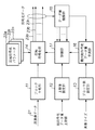
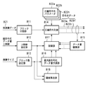
図1は、本発明の第2の実施形態による画像圧縮符号化装置の構成を示すブロック図である。図1に示すように、本実施形態における画像圧縮符号化装置は、ブロック分割部11(ブロック分割手段)、上限値設定部12(上限値設定手段)、ブロック数設定部13(ブロック数設定手段)、圧縮符号化部14(圧縮符号化手段)、データ量積算部15(符号化データ量積算手段)、最大総符号化データ量予測部16(最大総符号化データ量予測手段)及び制御部17(制御手段)から構成される。
【0056】
ブロック分割部11は、本実施形態による画像圧縮符号化装置に入力される原画像データ21を、所定の大きさのブロックに分割し、圧縮符号化部14に出力する。また、上限値設定部12には、ブロックに分割された原画像データの全てを符号化した際に得られる総符号化データ量上限値が設定される。さらに、ブロック数設定部13では、原画像データの大きさとブロックの大きさに応じて決定されるブロックの数が画像サイズとして設定され保持される。
【0057】
圧縮符号化部14は、複数の符号化パラメータ22a〜22nを用いて、ブロックに分割された原画像データを圧縮符号化し、複数の符号化データ列23a〜23nを並列に出力する。データ量積算部15は、圧縮符号化部14から出力された符号化データ列23a〜23nのデータ量をそれぞれ計数して積算し、累積データ量を出力する。
【0058】
最大総符号化データ量予測部16は、ブロック数設定部13で設定された総ブロック数と既に圧縮符号化されたブロック数とから得られる残りのブロック数と、1ブロック当たりの最大符号化データ量と、データ量積算部15によって積算された符号化データ量積算値(累積データ量)が最も大きい符号化データ列の符号化データ量積算値を基に、残りのブロックを符号化した際にそれら全てのブロックの符号化データ量が最大であるときのデータ量である最大総符号化データ量予測値を算出する。
【0059】
制御部17は、データ量積算部15によって積算された複数の符号化データ量積算値と、上限値設定部12に設定された総符号化データ量上限値とを比較する。そして、上限値を超えたものがあれば、該当する圧縮符号化パラメータでの圧縮符号化処理を打ち切る処理が行われる。また、最大総符号化データ量予測値が、総符号化データ量の上限値を超えないと判断した時点で、該当する圧縮符号化パラメータ以外での圧縮符号化処理を打ち切る。
【0060】
尚、本発明に係る画像圧縮符号化装置においては、1ブロック当たりの最大符号化データ量及びその算出方法は規定されない。
【0061】
1ブロック当たりの最大符号化データ量は、ブロックの大きさ、圧縮符号化方式、圧縮符号化パラメータに依存する。一例として、圧縮符号化方式として静止画の代表的な圧縮符号化方式であるJPEG符号化を本実施形態の画像圧縮符号化装置に用いた場合の、1ブロック当たりの最大符号化データ量について述べる。
【0062】
JPEG符号化では、DCTによって得られる直交変換係数を量子化した後、エントロピー符号化が行われる。尚、エントロピー符号化として、ハフマン符号化方式が用いられる。最大符号化データ量は、量子化を行う際に用いられる量子化テーブルと、直交変換係数中のDC成分の差分値及び無効係数のランレングスと有効係数の組のそれぞれに割り当てられるハフマン符号と付加ビット長に依存する。これらから理論上の最大符号化データ量を求める方法が考えられる。
【0063】
また、JPEG符号化方式では、隣接する画素間の相関度が低い画像ほど圧縮率が悪くなるので、そのような画像をサンプルとしていくつか符号化処理を行い、その中で最も符号化データ量が大きかったものを最大符号化データ量として実測統計的に求める方法も考えられる。
【0064】
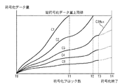
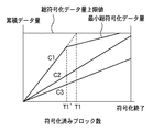
図2は、第2の実施形態による画像圧縮符号化装置における上限値設定部12で設定される総符号化データ量上限値と、圧縮符号化部14によって生成され、データ量積算部15によって積算された符号化データ量(縦軸)と、その時点で既に圧縮符号化処理されたブロックの原画像データにおける相対位置(横軸)との関係を説明するためのグラフである。また、図3は、図2に示されるブロックT0、T1、T2、T3及びT4の原画像データにおける相対位置を説明するための概要図である。
【0065】
以下、図面を参照して、本実施形態による画像圧縮符号化装置の動作手順について説明する。図4は、第2の実施形態による画像圧縮符号化装置の動作手順について説明するためのフローチャートである。上述したように、本装置に入力された原画像データ21は、ブロック分割部11において、複数の所定の大きさのブロックに分割される(ステップS41)。そして、圧縮符号化部14では、分割されたブロックを複数の符号化パラメータを用いて圧縮符号化する(ステップS42)。尚、本実施形態では5つのパラメータを用いて圧縮符号化がされる場合について説明する。
【0066】
すなわち、本実施形態による画像圧縮符号化装置は、図3に示すブロックT0から圧縮符号化処理を開始し、各ブロックについて、図2に示す圧縮率の異なる5つの符号化データ列C1〜C5を出力する。そして、データ量積算部15において、圧縮符号化部14から出力された5つの符号化データ列のデータ量がそれぞれ計数して積算される(ステップS44)。そして、制御部17では、データ量積算部15において積算された符号化データ量積算値と、上限設定部12に設定された上限値とが比較される(ステップS45)。
【0067】
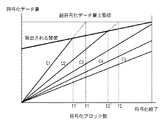
その結果、符号化データ量積算値が上限値を超える場合(Yes)、該当する符号化パラメータによる圧縮処理が打ち切られる(ステップS46)。尚、以降のブロックの圧縮処理では、当該符号化パラメータ以外のものを用いて行われる。図2のグラフに示すように、本実施形態による画像圧縮符号化装置は、ブロックT1まで圧縮符号化処理を終えた時点で、符号化データ列C1の符号化データ量積算値が総符号化データ量上限値を超えるので、符号化データ列C1の符号化処理が打ち切られる。すなわち、以降のブロックについては、C2〜C5の4つの符号化データ列を出力するようにする。また、ブロックT2まで圧縮符号化処理が終了した時点においても符号化データ列C2が総符号化データ量上限値を超えるので、符号化データ列C2の符号化処理が打ち切られる。すなわち、以降のブロックについては、C3〜C5の3つの符号化データ列を出力するようにする。
【0068】
一方、積算値が上限値を超えない場合(No)、最大総符号化データ量予測部16において、最大総符号化データ量予測値が算出される(ステップS47)。そして、制御部17では、当該最大総符号化データ量予測値と、上限設定部12に設定されら上限値とが比較される(ステップS48)。
【0069】
その結果、最大総符号化データ量予測値が上限値を超える場合(Yes)、該当する符号化パラメータ以外による圧縮処理が打ち切られる(ステップS49)。
【0070】
例えば、ブロックT3まで圧縮符号化処理がされたとき、最大総符号化データ量予測値C3Maxが総符号化データ量上限値を超えないと判断されるので、制御部17によってC3よりも圧縮率の高い符号化データ列C4〜C5での圧縮符号化処理が打ち切られる。すなわち、以降の処理については、符号化データ列C3のみが出力されるようになる。最終的に、ブロックT4まで圧縮符号化処理を終えた時点で、原画像を構成する全てのブロックに対する圧縮符号化処理が終了し、本実施形態の画像圧縮符号化装置の生成した符号化データ列はC3となる。
【0071】
以上説明したように、本実施形態における画像圧縮符号化装置は、ブロックに分割された原画像データを圧縮符号化する際に、圧縮符号化処理を終えていない全てのブロックを符号化したときのデータ量が最大になるような画像であったとしても総符号化データ量上限値を超えないと判断した時点で、該当する符号化データ列の圧縮に用いた圧縮符号化パラメータ以外での圧縮符号化処理を打ち切り、当該符号化データ列を本実施形態における画像圧縮符号化装置が出力する圧縮符号化データとして選択する。
【0072】
図5は、また、第2の実施形態における画像圧縮符号化装置が、外部システムにおいて符号化データを格納するメモリに接続されている様子を説明するための概要図である。図5に示すように、画像圧縮符号化装置10から出力された符号化データ列23a〜23nは、バス制御部52によって制御されるバスを介して、メモリ51へ転送される。
【0073】
図5に示すように、本実施形態の画像圧縮符号化装置を備えるシステムは、符号化データ量積算値が総符号化データ量上限値を超えず、かつ、総符号化データ量上限値に最も近い符号化データ列を原画像の圧縮符号化データとしてメモリ51に格納し、それ以外の符号化データは破棄する。図5に示したシステムでは、符号化データ列が多いほどメモリへの転送時のオーバーヘッドが大きく、メモリ転送待ちの間に画像圧縮符号化装置10は、圧縮符号化処理を一時中断しなければならない。その結果として画像圧縮符号化に要する時間が増大してしまう。
【0074】
ここで、上述したように、最大総符号化データ量予測値が総符号化データ量上限値を超えないと判断されたとき、該当する圧縮符号化パラメータ以外での圧縮符号化処理を打ち切ることにより、最終的にメモリ51から破棄される符号化データ列が出力されなくなる。従って、画像圧縮符号化装置外部へのデータ転送に伴うオーバーヘッドの低下を抑えることが可能となる。
【0075】
すなわち、本発明は、圧縮符号化された複数の符号化データを記憶する記憶手段(メモリ51)と、制御手段(制御部17)によって画像データの圧縮符号化処理が打ち切られた場合の圧縮率で圧縮符号化された符号化データを破棄する破棄手段(制御部17)とをさらに備えることを特徴とする。
【0076】
以上に説明したように、本実施形態による画像圧縮符号化装置は、原画像を構成する残りのブロックを符号化した際に、それら全てのブロックの符号化データ量が最大であるときの最大総符号化データ量予測値が、あらかじめ設定された総符号化データ量の上限値を超えなければ、該当する圧縮符号化パラメータ以外での圧縮符号化処理を打ち切るようにした。
【0077】
従って、ブロックに分割された原画像を全て圧縮符号化したときの総符号化データ量が、上限値を超えないことが自明になった時点で、該当する符号化データ列以外の符号化データ列が出力されないため、符号化データ列の転送に伴うオーバーヘッドが削減され、情報量制御を実現しつつ圧縮符号化処理を行う場合の処理時間を短縮することができるという効果が得られる。
【0078】
尚、本実施形態の画像圧縮符号化装置においては、圧縮符号化部14は、符号化されたブロックのデータ量が原画像のブロックのデータ量を超えた場合でも、当該ブロックの符号化データ列をそのまま出力する。しかし、他の実施形態によっては、原画像をそのまま出力することも可能である。この場合、ブロックの最大符号化データ量は、ブロックに分割された原画像のデータ量となる。このような実施形態による画像圧縮符号化装置では、総符号化データ量を一定値以内に抑えつつ圧縮符号化する処理をさらに効率よく行うことができる。
【0079】
<第3の実施形態>
次に、本発明の第3の実施形態に係る画像圧縮符号化装置について説明する。図6は、本発明の第3の実施形態による画像圧縮符号化装置の構成を示すブロック図である。図6に示すように、本実施形態の画像圧縮符号化装置は、ブロック分割部31(ブロック分割手段)、上限値設定部32(上限値設定手段)、ブロック数設定部33(ブロック数設定手段)、圧縮符号化部34(圧縮符号化手段)、制御部35(制御手段)、最大総符号化データ量予測部36(最大総符号化データ量予測手段)、データ量積算部37(符号化データ量積算手段)、メモリ38(記憶手段)、再圧縮符号化部39(再符号化手段)及び符号化データ入出力制御部40(出力制御手段)から構成される。
【0080】
以下、図6を参照して、本実施形態による画像圧縮符号化装置の詳細について説明する。ブロック分割部31は、画像圧縮符号化装置に入力される原画像データ41を、所定の大きさのブロックに分割し、圧縮符号化部34に出力する。また、上限値設定部32には、ブロックに分割された原画像データの全てを符号化した際に得られる総符号化データ量の上限値が設定される。さらに、ブロック数設定部33には、原画像データの大きさとブロックの大きさに応じて決定されるブロックの数が画像サイズとして設定され保持される。
【0081】
一方、圧縮符号化部34は、圧縮符号化パラメータ42a〜42nのうち制御部35によって指定された圧縮符号化パラメータを用いて、ブロック分割部31によって所定の大きさのブロックに分割された原画像を圧縮符号化し、符号化データ列43a及び43bを出力する。尚、符号化データ列43bは、符号化データ列43aよりも圧縮率が高いものとする。そして、符号化データ列43aは、画像圧縮符号化装置外部へ出力され、符号化データ列43bはメモリ38へ出力される。
【0082】
再圧縮符号化部39は、制御部35からの指示により、メモリ38に一時的に格納された符号化データ列を再圧縮符号化し、符号化データ列44を出力する。また、データ量積算部37は、符号化データ列43a、43b及び44のデータ量を計数し積算する。ここで、符号化データ列43b及び44のデータ量積算値は合計されて、最大総符号化データ量予測部36へ出力される。
【0083】
また、最大総符号化データ量予測部36は、ブロック数設定部33で設定された総ブロック数と既に圧縮符号化されたブロック数とから得られる残りブロック数と、1ブロック当たりの最大符号化データ量と、符号化データ量積算部37から得られる符号化データ列43b及び44のデータ量積算値の合計値を基に、原画像を構成する残りのブロックを符号化した際に、それら全てのブロックの符号化データ量が最大であるときのデータ量である最大総符号化データ量予測値を算出する。
【0084】
さらに、制御部35は、データ量積算部37によって積算された符号化データ列43aの符号化データ量積算値(累積データ量)と、上限値設定部32に設定された総符号化データ量の上限値を比較し、上限値を超えていれば以下の処理を行う。
【0085】
まず、最大総符号化データ量予測値が総符号化データ量の上限値を超えている場合、符号化データ列43a及び43bの生成に用いる圧縮符号化パラメータを変更し、再圧縮符号化部39に対しメモリ38に一時的に格納されている符号化データ列の再圧縮符号化処理を行う指示を出す。そして、符号化データ入出力制御部40に対し、メモリ38へ一時的に格納されていた符号化データ列を本実施形態による画像圧縮符号化装置外部へ出力する制御と、再圧縮符号化部39へ符号化データ列を入出力する制御を行う旨の指示を出す。
【0086】
一方、最大総符号化データ量予測値が総符号化データ量の上限値を超えていない場合、符号化データ列43aの生成に用いる圧縮符号化パラメータを変更し、符号化データ列43bの生成を打ち切る。そして、符号化データ入出力制御部40に対し、メモリ38に一時的に格納されていた符号化データ列を本実施形態の画像圧縮符号化装置外部へ出力する旨の指示を出す。この場合、再圧縮符号化部39は再圧縮符号化処理を行わない。
【0087】
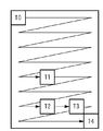
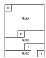
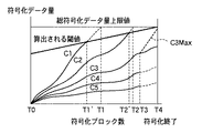
ここで、本実施形態の画像圧縮符号化装置が、原画像の圧縮符号化処理に要する時間について説明する。図7は、第3の実施形態による画像圧縮符号化装置が生成した符号化データ列の符号化データ量積算値(縦軸)と、原画像の圧縮符号化処理に要した時間(横軸)との関係を説明するためのグラフである。また、図8は、図7のグラフ上で示される時刻t0、t1、t2及びt3の時点で圧縮符号化処理を終えたブロックの原画像データ上の相対位置T0、T1、T2及びT3と、3つの分割領域A、B及びCを2次元的に表現された原画像データ上で表わした図である。
【0088】
図7のグラフに示す時刻t1までは符号化データ列C1が本実施形態による画像圧縮符号化装置外部へ出力され、符号化データ列C2が図2に示したメモリ38に一時的に格納される。図8に示した原画像データのブロックT1まで圧縮符号化処理を終了した時点(すなわち、図6における時刻t1の時点)で、符号化データ列C1の符号化データ量積算値が総符号化データ量上限値を超える。
【0089】
このとき、最大総符号化データ量予測部36によって算出された符号化データ列C2の最大総符号化データ量予測値C2Maxが総符号化データ量上限値を超える。従って、最終的に、図8に示す原画像を全て符号化した際に得られる総符号化データ量は、総符号化データ量上限値を超える可能性があるものとする。
【0090】
ここで、本実施形態による画像圧縮符号化装置の制御部35は、符号化データ列C1を生成する圧縮符号化処理を打ち切ると同時に、ブロックT1の次のブロックからは符号化データ列C2及びC3を生成する圧縮符号化処理を開始する制御を行う。
【0091】
さらに、再圧縮符号化部39に対し、メモリ38に格納されていた図8に示す領域Aの原画像を符号化した符号化データ列C2を再圧縮符号化して、符号化データ列C3を生成し、再びメモリ38に格納する旨の指示を出す。また、符号化データ入出力制御部40は、メモリ38に格納されていた図8における領域Aの原画像を符号化した符号化データ列C2を、本実施形態による画像圧縮符号化装置外部へ出力する。尚、図7に示した時刻t1以降は、符号化データ列C2は、本実施形態による画像圧縮符号化装置外部へ出力され、前記符号化データ列C3はメモリ38に一時的に格納される。
【0092】
時刻t2において、図8に示したブロックT2まで符号化された時点で、図7の符号化データ列C2の符号化データ量積算値が、総符号化データ量上限値を超えるので、制御部35は符号化データ列C2の生成を打ち切る。このとき、最大総符号化データ量予測部36によって算出された最大総符号化データ量予測値C3Maxが、総符号化データ量上限値を超えない。従って、時刻t2の時点で符号化処理を終えていない図8の領域Cを全て符号化したとしても、符号化データ列C3の総符号化データ量は総符号化データ量上限値を超えない。
【0093】
従って、制御部35は、図7に示す符号化データ列C4を生成する圧縮符号化処理の開始を指示せず、図8の領域A及びBを符号化した符号化データ列C3を再圧縮符号化処理する指示を行わない。また、符号化データ入出力制御部40は、メモリ38に一時的に格納されている前記領域A及びBの符号化データ列C3を出力する。
【0094】
最終的に、ブロックT3まで圧縮符号化処理を終えた時点で、原画像を構成する全てのブロックに対する圧縮符号化処理が終了し、本実施形態の画像圧縮符号化装置の生成した符号化データ列はC3となる。
【0095】
以上説明した処理がなされることにより、本実施形態による画像圧縮符号化装置は、総符号化データ量があらかじめ設定された上限値を超えないと判断した場合、該当する符号化データ列以外の符号化処理を打ち切る。従って、圧縮符号化部34が出力する符号化データ列が減るので、図4で示した第2の実施形態による画像圧縮符号化装置と外部メモリとの接続で説明した場合と同様に、符号化データ列の画像圧縮符号化装置外部への転送に伴うオーバーヘッドが削減される。また、上記の場合には再圧縮符号化処理が行われないので、再符号化部39とメモリ38間の符号化データ列の転送が行われず、符号化データ列の出力に伴うオーバーヘッドが削減される。
【0096】
尚、本実施形態の説明においては、画像データの圧縮符号化方式としてJPEG圧縮符号化方式を取り上げたが、本発明の画像圧縮符号化装置は画像データの種類及びその圧縮符号化方式は限定されない。例えば、画像データとして、画像を構成する画素が文字であるか否か、有彩色か無彩色かなど、画像の属性を表すデータをランレングス圧縮符号化するような場合にも、本発明に係る画像圧縮符号化装置を適用することができる。
【0097】
また、本発明の第3の実施形態による画像圧縮符号化装置は、原画像を構成する残りのブロックを符号化した際にそれら全てのブロックの符号化データ量が最大であるときの最大総符号化データ量予測値が、あらかじめ設定された総符号化データ量の上限値を超えなければ、該当する圧縮符号化パラメータ以外での圧縮符号化処理を打ち切り、再圧縮符号化処理が行われないようにした。
【0098】
従って、符号化データ量積算値が総符号化データ量上限値を超えたとき、ブロックに分割された原画像を全て圧縮符号化したときの総符号化データ量が前記上限値を超えないことが自明である場合、該当する圧縮符号化パラメータ以外での圧縮符号化処理と、メモリに格納された符号化データ列に対する再符号化処理を行わないため、符号化データ列の転送に伴うオーバーヘッドが削減され、情報量制御を実現しつつ圧縮符号化処理を行う場合の処理時間を短縮できるという効果が得られる。
【0099】
<第4の実施形態>
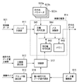
次に、本発明に係る第4の実施形態における画像圧縮符号化装置について、図面を参照しながら具体的に説明する。図9は、本発明の第4の実施形態における画像圧縮符号化装置の構成を示すブロック図である。本実施形態による画像圧縮符号化装置は、ブロック分割部111(ブロック分割手段)、ブロック数設定部112(ブロック数設定手段)、上限値設定部113(上限値設定手段)、圧縮符号化部114(圧縮符号化手段)、データ量積算部115(データ量積算手段)、閾値算出部116(閾値算出手段)、制御部117(制御手段)から構成される。
【0100】
ブロック分割部111は、本実施形態の画像圧縮符号化装置に入力される原画像データ121を、所定の大きさのブロックに分割し、圧縮符号化部114に出力する。ブロック数設定部112には、原画像データの大きさとブロックの大きさに応じて決定されるブロックの数が画像サイズとして設定され保持される。上限値設定部113には、ブロックに分割された原画像データの全てを符号化した際に得られる総符号化データ量の上限値が設定される。
【0101】
圧縮符号化部114は、複数の符号化パラメータ122a〜122nを用いて、ブロックに分割された原画像データを圧縮符号化し、複数の符号化データ列123a〜123nを出力する。データ量積算部115は、符号化データ列123a〜123nのデータ量を計数し、累積データ量を積算する。
【0102】
閾値算出部116は、ブロック数設定部112に設定されたブロック数と、圧縮符号化部114によって符号化されたブロックの原画像データにおける相対的な位置と、上限値設定部113に設定された上限値と、圧縮符号化方式に基づく理論上の最低符号量を基に、符号化データ量の閾値を算出する。本実施形態の画像圧縮符号化装置においては、1ブロックあたりの最小符号量を、圧縮符号化方式に基づく理論上の最小符号量とする。
【0103】
ここで、理論上の最低符号量を、静止画の圧縮符号化において広く用いられているJPEG符号化方式を例にとって説明する。例えば、白画素のみから成る画像をJPEG符号化した場合、DCTによって周波数変換されたときのDC成分の隣接するブロックのDC成分との差分値は0である。このときのハフマン符号は“00”の2ビットである。また、AC成分は全て0であり、EOBで表現され、EOBのハフマン符号は“1010”の4ビットである。従って、1ブロック当たりの最低符号量は6ビットとなる。
【0104】
また、最低符号量は、ブロックに分割された原画像を構成しJPEGにおけるDCTの単位となる小ブロックの1ブロック当たりの個数や、コンポーネント数、サブサンプル数にも依存する。さらにJPEGのECS符号化部だけではなく、EOIマーカやリスタートマーカ、ヘッダなどのマーカコードの数にも依存する。あるいは、ブロックに分割され圧縮符号化されたデータをパケット化し、各々のパケットにヘッダを付加するような場合は、そのパケットの大きさも最低符号量に関わる。よって1ブロックの最低符号量は、6ビットよりも大きくなり、画像圧縮符号化装置を含むシステムの仕様に依存する。
【0105】
本実施形態による画像圧縮符号化装置おける閾値を算出する方法の一例を次に示す。すなわち、1ブロック当たりの理論上の最低符号量をL、総符号化データ量の上限値をH、総ブロック数と原画像データにおけるブロックの相対位置情報から求められる符号化処理を終えていない残りのタイル数をRとする。このとき、閾値Tは、
T=H−L×R (2)
で与えられる。
【0106】
本実施形態における画像圧縮符号化装置では、1ブロックの圧縮符号化処理が行われる毎に閾値が算出されるが、演算量を考慮して、複数タイルの圧縮符号化処理が行われた時点で上記閾値を算出するようにしてもよい。また、画像データの符号化処理を開始する前に初期の閾値を求め、1ブロックの圧縮符号化処理が行われる毎に、1ブロックの最低符号量を加算していく方法で閾値を算出する方法であってもよい。
【0107】
この場合、総ブロック数をBとすると、初期の閾値T’は
T’=H−L×B (3)
で求められる。
【0108】
そして、初期の閾値T’に、1ブロックの圧縮符号化処理が行われる毎に最低符号量Lを累積加算していくことで、閾値Tを得られる。
【0109】
制御部117は、閾値算出部116で算出された閾値と、データ量積算部115で計数され積算された複数の符号化データ量積算値を比較し、閾値を超えたものがあれば、該当する符号化データ列生成に用いた符号化パラメータでの圧縮符号化処理を打ち切る制御を圧縮符号化部114に対して行う。これは、前述したように、算出された閾値を超えた場合、以後の原画像のタイルを符号化したときに符号化データ量積算値が総符号化データ量上限値を超えることが明らかであるためである。
【0110】
図10は、図9に示す上限値設定部113に設定された総符号化データ量上限値と、閾値算出部116によって算出された閾値と、圧縮符号化部114が生成しデータ量積算部115によって積算された符号化データ量(縦軸)と、その時点で既に圧縮符号化処理がなされているブロックの原画像データにおける相対位置(横軸)との関係を示すグラフである。
【0111】
図10において、符号T1は、符号化データ列C1の符号化データ量積算値が総符号化データ量上限値に達した時点までに符号化処理がなされたブロック数を示す。T1’は、符号化データ列C1の符号化データが閾値算出部116で算出された閾値に達した時点までに符号化処理がなされたブロック数を示す。本実施形態の画像圧縮符号化装置は、符号化データ列C1がブロックT1’まで生成され符号化データ量積算値が閾値を超えたとき、C1の符号化処理が打ち切られる。また、C2が閾値を超えるブロックT2’においても同様に符号化処理が打ち切られる。このように、総符号化データ量上限値を超えたときよりも早くC1及びC2の符号化処理が打ち切られる。
【0112】
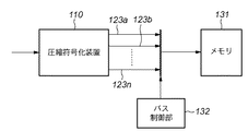
図11は、第4の実施形態の画像圧縮符号化装置が、外部システムにおいて符号化データを格納するメモリに接続されている様子を示す図である。圧縮符号化装置110から出力された符号化データ列123a〜123nは、バス制御部132によって制御されるバスを介してメモリ131へ転送される。本実施形態の画像圧縮符号化装置を備えるシステムは、符号化データ量積算値が総符号化データ量上限値を超えず、かつ、総符号化データ量上限値に最も近い符号化データ列を、原画像の圧縮符号化データとしてメモリ131に格納し、それ以外の符号化データは破棄する。
【0113】
図11に示したシステムでは、符号化データ列が多いほどメモリへの転送時のオーバーヘッドが大きく、メモリ転送待ちの間、画像圧縮符号化装置は圧縮符号化を一時中断しなければならない。その結果として画像圧縮符号化に要する時間が増大する。ここで、上述したように1ブロック当たりの最低符号量と原画像におけるブロックの相対位置に基づいて算出した閾値を超えた時点で符号化処理を打ち切ることにより、総符号化データ量上限値を超えることが自明な符号化データ列がメモリに転送されなくなる。従って、画像符号化装置外部へのデータ転送に伴うオーバーヘッドの低下を抑えることが可能となる。
【0114】
以上説明したように、第4の実施形態における画像圧縮符号化装置は、あらかじめ設定された総符号化データ量の上限値と、圧縮符号化方式に基づく1ブロック当たりの理論上の最低符号化データ量と、ブロック数設定手段に設定された総ブロック数と、圧縮符号化手段により圧縮符号化されたブロックの画像データにおける相対位置情報を基に算出された閾値を、圧縮率の異なる複数の符号化データ列の符号化データ量積算値のうち上回ったものがあった場合に、該当する圧縮符号化パラメータでの圧縮符号化処理が打ち切られるようにした。
【0115】
従って、総符号化データ量上限値を超えることが自明な符号化データ列の符号化データ量積算値が総符号化データ量上限値を超える前に符号化処理が打ち切られるため、圧縮率の異なる符号化データ列を並列に出力し伝送路を介して外部メモリなどに転送した場合のオーバーヘッドを削減でき、情報量制御を実現しつつ圧縮符号化処理を行う場合の処理速度が向上するという効果が得られる。
【0116】
さらに、本発明の第1の実施形態と第4の実施形態を比較した場合、第2の実施形態において式(3)により初期閾値を算出した後、所定ブロック数の符号化が終了する毎に所定ブロック数の最小符号量を加算する方法によれば、演算量を削減できるという効果も得られる。
【0117】
<第5の実施形態>
次に、本発明に係る第5の実施形態による画像圧縮符号化装置を説明する。本実施形態の画像圧縮符号化装置は、図9に示した第4の実施形態の画像圧縮符号化装置が備える圧縮符号化部114の内部が、図12に示す画像圧縮符号化部141、再圧縮符号化部142、メモリ143、制御部144から構成されている点で異なる。すなわち、図12は、第5の実施形態の画像圧縮符号化装置が、外部システムにおいて符号化データを格納するメモリに接続されている場合の様子を示すブロック図である。以下、図12を参照して、本実施形態による画像圧縮符号化装置について詳細に説明する。
【0118】
画像圧縮符号化部141は、制御部17によって指定された符号化パラメータを用い、ブロックに分割された原画像データを圧縮符号化する。バス制御部144は、符号化データ列を圧縮符号化部114の外部に出力し、同時にメモリ143に書き込む。データ量積算部115は圧縮符号化部114から出力された符号化データ列の符号化データ量を計数して積算し、累積データ量を算出する。
【0119】
閾値算出部116は、ブロック数設定部112に設定されたブロック数と、圧縮符号化部114によって符号化されたブロックの原画像データにおける相対的な位置と、上限値設定部113に設定された上限値と、1ブロックあたりの最小符号量を基に、累積データ量の閾値を算出する。
【0120】
制御部117は、符号化データ量積算値を閾値算出部16によって算出された閾値と比較し、前記符号化データ量積算値が閾値を超えていれば、画像圧縮符号化部141に対し圧縮符号化処理停止の指示を出し、再圧縮符号化部143に対しメモリ143に蓄積されていた符号化データ列を再圧縮符号化する旨の指示を出す。制御部144は、メモリ143に蓄積されていた符号化データ列を再圧縮符号化部142に入力し、再圧縮符号化された符号化データ列を圧縮符号化部114の外部に出力し、同時にメモリ143に書き込む動作を開始する。
【0121】
そして、符号化データ量積算値が閾値を超えた時点までに符号化されたブロックの全てに対して再符号化処理を行った後、制御部117は再圧縮符号化部142に対して再圧縮符号化処理の停止を指示し、画像圧縮符号化部141に対し符号化パラメータを変更して圧縮符号化処理を再開する旨の指示を出す。尚、本実施形態における画像圧縮符号化装置においては、圧縮率の異なる複数の符号化データは並列には出力されない。
【0122】
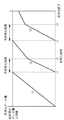
図13及び図14は、第5の実施形態における画像圧縮符号化装置の圧縮符号化部114が生成しデータ量積算部115によって積算された符号化データ量積算値(縦軸)と、原画像の圧縮符号化処理に要した時間(横軸)との関係を表すグラフである。すなわち、図13のグラフでは、符号化データ量積算値が総符号化データ量上限値で再符号化処理を開始した場合に、符号化処理及び再符号化処理に要した時間が示される。また、図14のグラフでは、符号化データ量積算値が閾値を超えた時点で再符号化処理を開始した場合に、符号化処理及び再符号化処理に要した時間が示される。
【0123】
図13及び図14に示したグラフの比較から明らかなように、符号化データ量積算値が前記閾値を超えた時点で再符号化処理を開始した場合、総符号化データ量上限値で再符号化処理を開始した場合よりも再符号化処理時間が短縮される。従って、原画像データ全体の圧縮符号化処理に要する時間が削減される。
【0124】
以上説明したように、第5の実施形態における画像圧縮符号化装置は、あらかじめ設定された総符号化データ量の上限値と、圧縮符号化方式に基づく1ブロック当たりの理論上の最低符号化データ量と、ブロック数設定手段に設定された総ブロック数と、圧縮符号化手段により圧縮符号化されたブロックの画像データにおける相対位置情報を基に算出された閾値を、符号化データ列の符号化データ量積算値が上回った場合に、再圧縮符号化手段に再圧縮符号化の開始が指示されるようにした。従って、ある圧縮符号化パラメータを用いて圧縮された符号化データ列のデータ量が総符号化データ量上限値を超えることが明らかになった時点で即座に再圧縮符号化処理を開始するため、再符号化処理によるオーバーヘッドを削減でき、再圧縮符号化処理による情報量制御を実現しつつ圧縮符号化処理を行う場合の処理速度が向上するという効果が得られる。
【0125】
<第6の実施形態>
次に、本発明に係る第6の実施形態の画像圧縮符号化装置について説明する。本実施形態の画像符号化装置は、複写機など光学読み取り装置を備える製品に搭載されることを想定している。本実施形態の画像圧縮符号化装置は、図9に示した第4の実施形態の画像圧縮符号化装置と同一構成であるが、閾値算出部116が、画像の実測統計上の最低符号量に基づいて閾値を逐次算出する点で異なる。ここで、実測統計上の最低符号量とは、例えば、本実施形態の画像圧縮符号化装置が、複写機等の光学読み取り装置によってスキャンされた原画像の光学的なブレを考慮したものである。
【0126】
例えば、白画素のみから成る下地の画像をスキャンした場合でも、光学的なブレや雑音が入り得るので、実際は、全く無為のブロックが画像圧縮符号化装置に入力されるわけではない。そのため、原画像を構成するブロックを圧縮符号化した場合でも、その符号化データ量は圧縮符号化方式に基づく理論上の最低符号量よりも多いと考えられる。そこで、白画素のみから成る下地の原画像データが光学読み取り装置によって読み取られた場合の最低符号量を実測し統計を取り、本画像符号化装置が備える閾値算出部116が閾値を算出する際に、実測統計上の最低符号量を用いるようにする。
【0127】
本実施形態の画像圧縮符号化装置の構成を図9に示す。本実施形態の画像符号化装置は、ブロック分割部111(ブロック分割手段)、上限値設定部112(上限値設定手段)、ブロック数設定部113(ブロック数設定手段)、圧縮符号化部114(圧縮符号化手段)、データ量積算部115(データ量積算手段)、閾値算出部116(閾値算出手段)、制御部117(制御手段)から構成される。
【0128】
本実施形態の画像符号化装置のブロック分割部111(ブロック分割手段)、上限値設定部112(上限値設定手段)、ブロック数設定部113(ブロック数設定手段)、圧縮符号化部114(圧縮符号化手段)、データ量積算部115(データ量積算手段)の動作は、本発明の第4の実施形態においてそれぞれ対応するものと同じである。閾値算出部116は、ブロック数設定部113に設定されたブロック数と、圧縮符号化部114によって符号化されたブロックの原画像データにおける相対的な位置と、上限値設定部112に設定された上限値と、1ブロックあたりの最小符号量を基に、累積データ量の閾値を算出する。
【0129】
ここで、閾値算出部116は、原稿の種類、画像補正情報、読み取り雑音係数、画像特徴情報、符号化パラメータ122a〜122nを参照して前記最小符号量を算出する。以下、最小符号量の補正について説明する。
【0130】
原稿の種類131は、複写機のスキャナ部で読み取られる原稿の種類を表すパラメータである。原稿の質によって、スキャナから読み取られる画像の隣接する画素間の相関度が異なるため、符号化データ量も異なる。画像補正情報132は、ブロック分割部111に入力される原画像データに対して成された画像補正処理のパラメータである。エッジ強調処理を行なった場合は隣接する画素間の相関度が高くなるため符号量が増え、平滑化処理を行なった場合は隣接する画素間の相関度が低くなるため符号量が減る。読み取り雑音係数は、光学読み取り装置によってスキャンされた原画像の光学的なブレや雑音に基づくパラメータである。雑音が多いほど、隣接する画素間の相関度が高くなるため符号量が増える。画像特徴情報は、スキャナから読み取られた画像の特徴を抽出したものである。入力画像に文字が多い、網目模様の画像であるなどの情報が、画像圧縮符号化装置に入力される前に抽出される。文字や網目が多ければ符号量が増え、少なければ符号量が減る。閾値算出部116は、これらの情報を基に最小符号量を算出し、さらに、圧縮率の低い符号化パラメータに対応する最小符号化データ量を理論上の最小符号化データ量よりも大きく補正し、補正された最小符号化データ量を基に閾値を算出する。
【0131】
図15は、本発明に係る第6の実施形態の画像圧縮符号化装置の閾値算出部116が算出した閾値と、本発明に係る第4の実施形態の画像圧縮符号化装置の閾値算出部116が算出した閾値との比較を示すグラフである。図15のグラフから明らかなように、第4の実施形態の画像圧縮符号化装置では、ブロックT1まで符号化した時点で閾値に到達するが、第6の実施形態の画像圧縮符号化装置では、ブロックT1’まで符号化した時点で閾値に到達するので、符号化データ列C1の符号化処理を打ち切るタイミングが早まる。
【0132】
すなわち、本実施形態による画像圧縮符号化装置は、1ブロック当たりの実測統計上の最低符号化データ量に加えて、スキャナで読み取られる原稿の種類、画像補正情報、読み取り雑音係数及び画像特徴情報に基づいて閾値が算出されるようにしたので、第4の実施形態による画像圧縮符号化装置よりも、符号化データ量が総符号化データ量上限値を超えることが自明な符号化パラメータによる符号化処理の打ち切りをさらに早めることができるため、前述したオーバーヘッドをさらに削減でき、さらなる圧縮符号化処理速度の向上を図ることができるという効果が得られる。
【0133】
以上、第2から第6の実施形態で説明したように、本発明の各実施形態による画像圧縮符号化装置は、ディジタルイメージング機器のようにリアルタイム性及び性能が要求されるシステムにおいて、予測精度の高いフィードバック手法を用いた情報量制御を実現しつつ圧縮符号化処理を行う場合、一つの原画像データに対する一連の圧縮符号化処理に費やされる処理時間、特に、再符号化処理に係わるオーバーヘッドを最小限に抑え、かつ、伸長復号化処理によって得られる再構成画像において圧縮符号化歪みの局所的なばらつきを抑えながら、結果的に許容される圧縮率の範囲内で最も符号化歪みの小さい符号化データ列を得ることができるという効果が得られる。
【0134】
<第7の実施形態>
図18は、本発明の第7の実施形態による画像圧縮符号化装置の構成を示すブロック図である。図18に示すように、本実施形態における画像圧縮符号化装置は、ブロック分割部711(ブロック分割手段)、上限値設定部712(上限値設定手段)、ブロック数設定部713(ブロック数設定手段)、圧縮符号化部714(圧縮符号化手段)、データ量積算部715(符号化データ量積算手段)、最大総符号化データ量予測部716(最大総符号化データ量予測手段)、制御部717(制御手段)、画像補正情報718から構成される。
【0135】
本実施形態の画像符号化装置のブロック分割部711(ブロック分割手段)、上限値設定部712(上限値設定手段)、ブロック数設定部713(ブロック数設定手段)、圧縮符号化部714(圧縮符号化手段)、データ量積算部715(データ量積算手段)の動作は、本発明の第6の実施形態においてそれぞれ対応するものと同じである。
【0136】
画像補正情報718は、原画像データ721が入力される前に行なわれた画像補正処理のパラメータを表す。画像特徴情報719は、スキャナから読み取られた画像の特徴を抽出したものである。
【0137】
最大総符号化データ量予測部716は、画像補正情報718と、画像特徴情報719と、累積データ量が最も大きい符号化データの符号化パラメータを基に、1ブロックあたりの最大符号量を算出する。圧縮率の高い符号化パラメータの最大符号量は、圧縮率の低い符号化パラメータの最大符号量よりも小さくなるように算出される。また、画像に対し平滑化処理がなされている場合は、最大符号量を小さくし、エッジ強調処理が成されている場合は大きくする。入力画像に文字や網目が多ければ符号量が増え、少なければ符号量が減る。
【0138】
そして、前記1ブロックあたりの最大符号量と、ブロック数設定部713で設定された総ブロック数と既に圧縮符号化されたブロック数とから得られる残りのブロック数と、データ量積算部715によって算出された累積データ量が最も大きい符号化データ列の累積データ量と、残りのブロックを符号化した際にそれら全てのブロックの符号量が最大であるときのデータ量である最大総符号化データ量予測値を算出する。
【0139】
制御部717は、データ量積算部715によって算出された複数の累積データ量と、上限値設定部712に設定された総符号化データ量上限値とを比較する。そして、上限値を超えたものがあれば、該当する圧縮符号化パラメータでの圧縮符号化処理を打ち切る処理が行われる。また、最大総符号化データ量予測値が、総符号化データ量の上限値を超えないと判断した時点で、該当する圧縮符号化パラメータ以外での圧縮符号化処理を打ち切る。
【0140】
図19は、第7の実施形態による画像圧縮符号化装置において算出される最大総符号化データ量予測値C3Max’と、本発明の第2の実施形態において算出される最大総符号化データ量予測値C3Maxを比較して説明するためのグラフである。
【0141】
ブロックT3まで符号化パラメータC3による符号化を終えた時点で算出される最大総符号化データ量予測値は、第2の実施形態においては総符号化データ量上限値を超える。一方、本実施形態においては、最大総符号化データ量予測値が符号化パラメータ及び画像補正情報に基づいて算出されるため、圧縮率の高いパラメータに対しては最大総符号化データ量が小さくなるので、図19に示したグラフにおいては総符号化データ量上限値を超えない。従って、ブロックT3の符号化処理を終えた時点で、符号化パラメータC4及びC5による圧縮符号化処理が打ち切られるので、符号化データ列の出力に伴うオーバーヘッドが削減される。
【0142】
<第8の実施形態>
図20は、本発明の第8の実施形態における画像圧縮符号化装置の構成を示すブロック図である。本実施形態の画像圧縮符号化装置は、本発明の第2の実施形態の画像圧縮符号化装置と第4の実施形態の画像圧縮符号化装置を組み合わせた構成になっている。
【0143】
本実施形態による画像圧縮符号化装置は、ブロック分割部811(ブロック分割手段)、上限値設定部812(上限値設定手段)、ブロック数設定部813(ブロック数設定手段)、圧縮符号化部814(圧縮符号化手段)、データ量積算部815(データ量積算手段)、最大総符号化データ量予測部816(最大符号化データ量予測手段)、制御部817(制御手段)、閾値算出部818(閾値算出手段)から構成される。
【0144】
ブロック分割部811は、本実施形態による画像圧縮符号化装置に入力される原画像データ821を、所定の大きさのブロックに分割し、圧縮符号化部814に出力する。また、上限値設定部812には、ブロックに分割された原画像データの全てを符号化した際に得られる総符号化データ量上限値が設定される。さらに、ブロック数設定部813では、原画像データの大きさとブロックの大きさに応じて決定されるブロックの数が画像サイズとして設定され保持される。
【0145】
圧縮符号化部814は、複数の符号化パラメータ822a〜822nを用いて、ブロックに分割された原画像データを圧縮符号化し、複数の符号化データ列823a〜823nを並列に出力する。データ量積算部815は、圧縮符号化部814から出力された符号化データ列823a〜823nのデータ量をそれぞれ計数し積算する。
【0146】
最大総符号化データ量予測部816は、ブロック数設定部813で設定された総ブロック数と既に圧縮符号化されたブロック数とから得られる残りのブロック数と、1ブロック当たりの最大符号量と、データ量積算部815によって算出された累積データ量が最も大きい符号化データ列の累積データ量を基に、残りのブロックを符号化した際にそれら全てのブロックの符号量が最大であるときのデータ量である最大総符号化データ量予測値を算出する。
【0147】
閾値算出部818は、ブロック数設定部813に設定されたブロック数と、圧縮符号化部814によって符号化されたブロックの原画像データにおける相対的な位置と、上限値設定部812に設定された上限値と、1ブロックあたりの最小符号量を基に、符号化データ量の閾値を算出する。
【0148】
制御部817は、データ量積算部815によって積算された複数の累積データ量と、閾値算出部818によって算出された符号化データ量の閾値を比較する。そして、閾値を超えたものがあれば、該当する圧縮符号化パラメータでの圧縮符号化処理を打ち切る処理が行われる。また、最大総符号化データ量予測値が、総符号化データ量の上限値を超えないと判断した時点で、該当する圧縮符号化パラメータよりも圧縮率が高いパラメータでの圧縮符号化処理を打ち切る。
【0149】
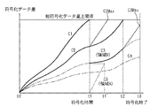
図21は、図20に示す上限値設定部812に設定された総符号化データ量上限値と、閾値算出部818によって算出された閾値と、圧縮符号化部814が生成しデータ量積算部815によって算出された累積データ量(縦軸)と、その時点で既に圧縮符号化処理がなされているブロックの原画像データにおける相対位置(横軸)との関係を示すグラフである。
【0150】
図21において、T1は、符号化データ列C1の累積データ量が総符号化データ量上限値に達した時点までに符号化処理がなされたブロック数を示す。T1'は、符号化データ列C1の符号化データが閾値算出部818で算出された閾値に達した時点までに符号化処理がなされたブロック数を示す。本実施形態の画像圧縮符号化装置は、符号化データ列C1がブロックT1’まで生成され累積データ量が閾値を超えたとき、C1の符号化処理が打ち切られる。また、C2が閾値を超えるブロックT2’においても同様に符号化処理が打ち切られる。このように、総符号化データ量上限値を超えたときよりも早くC1及びC2の符号化処理が打ち切られる。
【0151】
また、ブロックT3まで圧縮符号化処理がされたとき、最大総符号化データ量予測値C3Maxが総符号化データ量上限値を超えないと判断されるので、制御部817によってC3よりも圧縮率の高い符号化データ列C4〜C5での圧縮符号化処理が打ち切られる。すなわち、以降の処理については、符号化データ列C3のみが出力されるようになる。最終的に、ブロックT4まで圧縮符号化処理を終えた時点で、原画像を構成する全てのブロックに対する圧縮符号化処理が終了し、本実施形態の画像圧縮符号化装置の生成した符号化データ列はC3となる。
【0152】
以上説明したように、本実施形態の画像圧縮符号化装置においては、1ブロックあたりの最小符号量に基づいて算出した閾値を、累積データ量が上回った時点で、該当する圧縮符号化パラメータによる符号化処理を打ち切るようにした。また、1ブロックあたりの最大符号量に基づいて算出した最大総符号化データ量予測値が、総符号化データ量上限値を超えないと判断した時点で、該当するパラメータよりも圧縮率の高いパラメータによる符号化処理を打ち切るようにした。以上より、本実施形態の画像圧縮符号化装置においては、符号化データ列の出力に伴うオーバーヘッドが削減される。
【0153】
尚、本実施形態の説明においては、画像データの圧縮符号化方式としてJPEG圧縮符号化方式を取り上げたが、本発明の画像圧縮符号化装置は画像データの種類及びその圧縮符号化方式は限定されない。例えば、画像データとして、画像を構成する画素が文字であるか否か、有彩色か無彩色かなど、画像の属性を表すデータをランレングス圧縮符号化するような場合にも、本発明に係る画像圧縮符号化装置を適用することができる。
【0154】
以上、第1から第8の実施形態で説明したように、本発明の各実施形態による画像圧縮符号化装置は、ディジタルイメージング機器のようにリアルタイム性及び性能が要求されるシステムにおいて、予測精度の高いフィードバック手法を用いた情報量制御を実現しつつ圧縮符号化処理を行う場合、一つの原画像データに対する一連の圧縮符号化処理に費やされる処理時間、特に、再符号化処理に係わるオーバーヘッドを最小限に抑え、かつ、伸長復号化処理によって得られる再構成画像において圧縮符号化歪みの局所的なばらつきを抑えながら、結果的に許容される圧縮率の範囲内で最も符号化歪みの小さい符号化データ列を得ることができるという効果が得られる。
【0155】
<第9の実施形態>
図22は、本発明の第9の実施形態における画像圧縮符号化装置の構成を示すブロック図である。本実施形態の画像圧縮符号化装置は、ブロック分割部911(ブロック分割手段)、上限値設定部912(上限値設定手段)、ブロック数設定部913(ブロック数設定手段)、データ量積算部915(データ量積算手段)、最小総符号化データ量予測部916(最小総符号化データ量予測手段)、制御部917(制御手段)、画像圧縮部914から構成される。画像圧縮部914は、圧縮符号化部941(圧縮符号化手段)、再圧縮符号化部942(再圧縮符号化手段)、メモリ943、バス制御部944から構成される。以下、図22を参照して、本実施形態による画像圧縮符号化装置について詳細に説明する。
【0156】
圧縮符号化部941は、制御部917によって指定された符号化パラメータを用い、ブロック分割部911によってブロックに分割された原画像データを圧縮符号化する。バス制御部944は、符号化データ列を画像圧縮部914の外部に出力し、同時にメモリ943に書き込む。データ量積算部915は画像圧縮部914から出力された符号化データ列の符号化データ量を計数して積算し、累積データ量を算出する。
【0157】
最小総符号化データ量予測部916は、本発明の第1の実施形態における画像圧縮符号化装置が備える最小総符号化データ量予測部116と同様の方法により、累積データ量の最小総符号化データ量予測値を算出する。
【0158】
制御部917は、前記最小総符号化データ量予測部916によって算出された最小総符号化データ量予測値と、上限値設定部912に設定された上限値を比較し、前記最小総符号化データ量予測値が前記上限値を超えていれば、画像圧縮符号化部941に対し圧縮符号化処理停止の指示を出し、再圧縮符号化部943に対しメモリ943に蓄積されていた符号化データ列を再圧縮符号化する旨の指示を出す。制御部944は、メモリ943に蓄積されていた符号化データ列を再圧縮符号化部342に入力し、再圧縮符号化された符号化データ列を画像圧縮部914の外部に出力し、同時にメモリ943に書き込む動作を開始する。
【0159】
そして、前記最小総符号化データ量予測値が前記上限値を超えた時点までに符号化されたブロックの全てに対して再符号化処理を行った後、制御部917は再圧縮符号化部942に対して再圧縮符号化処理の停止を指示し、画像圧縮符号化部941に対し符号化パラメータを変更して圧縮符号化処理を再開する旨の指示を出す。尚、本実施形態における画像圧縮符号化装置においては、圧縮率の異なる複数の符号化データは並列には出力されない。
【0160】
図13及び図23はまた、第9の実施形態における画像圧縮符号化装置の圧縮符号化部941が生成しデータ量積算部915によって算出された累積データ量(縦軸)と、原画像の圧縮符号化処理に要した時間(横軸)との関係を表すグラフである。すなわち、図13のグラフでは、累積データ量が総符号化データ量上限値で再符号化処理を開始した場合に、符号化処理及び再符号化処理に要した時間が示される。また、図23のグラフでは、最小総符号化データ量予測値が総符号化データ量上限値を超えた時点で再符号化処理を開始した場合に、符号化処理及び再符号化処理に要した時間が示される。
【0161】
図13及び図23に示したグラフの比較から明らかなように、最小総符号化データ量予測値が総符号化データ量上限値を超えた時点で再符号化処理を開始した場合、累積データ量が総符号化データ量上限値を越えた時点で再符号化処理を開始した場合よりも再符号化処理時間が短縮される。従って、原画像データ全体の圧縮符号化処理に要する時間が削減される。
【0162】
以上説明したように、第9の実施形態における画像圧縮符号化装置は、圧縮符号化方式に基づく1ブロックあたりの理論上の最小符号量を基に算出された最小総符号化データ量予測値が総符号化データ量上限値を上回った場合に、再圧縮符号化手段に再圧縮符号化の開始が指示されるようにした。従って、ある圧縮符号化パラメータを用いて圧縮された符号化データ列のデータ量が総符号化データ量上限値を超えることが明らかになった時点で即座に再圧縮符号化処理を開始するため、再符号化処理によるオーバーヘッドを削減でき、再圧縮符号化処理による情報量制御を実現しつつ圧縮符号化処理を行う場合の処理速度が向上するという効果が得られる。
【0163】
<第10の実施形態>
図24は、本発明の第10の実施形態における画像圧縮符号化装置の構成を示すブロック図である。本実施形態の画像圧縮符号化装置は、本発明の第1の実施形態の画像圧縮符号化装置と第2の実施形態の画像圧縮符号化装置を組み合わせた構成になっている。
【0164】
本実施形態による画像圧縮符号化装置は、ブロック分割部1011(ブロック分割手段)、上限値設定部1012(上限値設定手段)、ブロック数設定部1013(ブロック数設定手段)、圧縮符号化部1014(圧縮符号化手段)、データ量積算部1015(データ量積算手段)、最大総符号化データ量予測部1016(最大総符号化データ量予測手段)、制御部1017(制御手段)、最小総符号化データ量予測部1018(最小総符号化データ量予測算出手段)から構成される。
【0165】
ブロック分割部1011は、本実施形態による画像圧縮符号化装置に入力される原画像データ1021を、所定の大きさのブロックに分割し、圧縮符号化部1014に出力する。また、上限値設定部1012には、ブロックに分割された原画像データの全てを符号化した際に得られる総符号化データ量上限値が設定される。さらに、ブロック数設定部1013では、原画像データの大きさとブロックの大きさに応じて決定されるブロックの数が画像サイズとして設定され保持される。
【0166】
圧縮符号化部1014は、複数の符号化パラメータ1022a〜1022nを用いて、ブロックに分割された原画像データを圧縮符号化し、複数の符号化データ列1023a〜1023nを並列に出力する。データ量積算部1015は、圧縮符号化部1014から出力された符号化データ列1023a〜1023nのデータ量をそれぞれ計数し積算する。
【0167】
最大総符号化データ量予測部1016は、ブロック数設定部1013で設定された総ブロック数と既に圧縮符号化されたブロック数とから得られる残りのブロック数と、1ブロック当たりの最大符号量と、データ量積算部1015によって算出された累積データ量が最も大きい符号化データ列の累積データ量を基に、残りのブロックを符号化した際にそれら全てのブロックの符号量が最大であるときのデータ量である最大総符号化データ量予測値を算出する。
【0168】
最小総符号化データ量予測部1018は、本発明の第1の実施形態が備える最小総符号化データ量予測部116と同様の方法により、最小総符号化データ量予測値を算出する。
【0169】
制御部1017は、総符号化データ量上限値と、最小総符号化データ量予測部1018によって算出された最小総符号化データ量予測値を比較する。そして、上限値を超えたものがあれば、該当する圧縮符号化パラメータでの圧縮符号化処理を打ち切る処理が行われる。また、最大総符号化データ量予測値が、総符号化データ量の上限値を超えないと判断した時点で、該当する圧縮符号化パラメータよりも圧縮率が高いパラメータでの圧縮符号化処理を打ち切る。
【0170】
図25は、図24に示す上限値設定部1012に設定された総符号化データ量上限値と、最小総符号化データ量予測部1018によって算出された最小総符号化データ量予測値と、圧縮符号化部1014が生成しデータ量積算部1015によって算出された累積データ量(縦軸)と、その時点で既に圧縮符号化処理がなされているブロックの原画像データにおける相対位置(横軸)との関係を示すグラフである。
【0171】
図25において、T1は、符号化データ列C1の累積データ量が総符号化データ量上限値に達した時点までに符号化処理がなされたブロック数を示す。T1'は、符号化データ列C1の符号化データが最小総符号化データ量予測部1018で算出された最小総符号化データ量予測値が上限値に達した時点までに符号化処理がなされたブロック数を示す。本実施形態の画像圧縮符号化装置は、符号化データ列C1がブロックT1'まで生成され、最小総符号化データ量予測値が上限値を超えたとき、C1の符号化処理が打ち切られる。また、C2が閾値を超えるブロックT2'においても同様に符号化処理が打ち切られる。このように、総符号化データ量上限値を超えたときよりも早くC1及びC2の符号化処理が打ち切られる。
【0172】
また、ブロックT3まで圧縮符号化処理がされたとき、最大総符号化データ量予測値C3Maxが総符号化データ量上限値を超えないと判断されるので、制御部517によってC3よりも圧縮率の高い符号化データ列C4〜C5での圧縮符号化処理が打ち切られる。すなわち、以降の処理については、符号化データ列C3のみが出力されるようになる。最終的に、ブロックT4まで圧縮符号化処理を終えた時点で、原画像を構成する全てのブロックに対する圧縮符号化処理が終了し、本実施形態の画像圧縮符号化装置の生成した符号化データ列はC3となる。
【0173】
以上説明したように、本実施形態の画像圧縮符号化装置においては、1ブロックあたりの最小符号量に基づいて算出した最小総符号化データ量予測値が、総符号化データ量上限値を上回った時点で、該当する圧縮符号化パラメータによる符号化処理を打ち切るようにした。また、1ブロックあたりの最大符号量に基づいて算出した最大総符号化データ量予測値が、総符号化データ量上限値を超えないと判断した時点で、該当するパラメータよりも圧縮率の高いパラメータによる符号化処理を打ち切るようにした。以上より、本実施形態の画像圧縮符号化装置においては、符号化データ列の出力に伴うオーバーヘッドが削減される。
【0174】
<第11の実施形態>
図26は、本発明の第11の実施形態における画像圧縮符号化装置の構成を示すブロック図である。本実施形態の画像圧縮符号化装置は、本発明の第3の実施形態の画像圧縮符号化装置と第5の実施形態の画像圧縮符号化装置を組み合わせた構成になっている。
【0175】
図26に示すように、本実施形態の画像圧縮符号化装置は、ブロック分割部1131(ブロック分割手段)、上限値設定部1132(上限値設定手段)、ブロック数設定部1133(ブロック数設定手段)、圧縮符号化部1134(圧縮符号化手段)、制御部1135(制御手段)、最大総符号化データ量予測部1136(最大総符号化データ量予測手段)、データ量積算部1137(符号化データ量積算手段)、メモリ1138(記憶手段)、再圧縮符号化部1139(再符号化手段)、符号化データ入出力制御部1140(出力制御手段)及び閾値算出部1150(閾値算出手段)から構成される。
【0176】
以下、図26を参照して、本実施形態による画像圧縮符号化装置の詳細について説明する。ブロック分割部1131は、画像圧縮符号化装置に入力される原画像データ1141を、所定の大きさのブロックに分割し、圧縮符号化部1134に出力する。また、上限値設定部1132には、ブロックに分割された原画像データの全てを符号化した際に得られる総符号化データ量の上限値が設定される。さらに、ブロック数設定部1133には、原画像データの大きさとブロックの大きさに応じて決定されるブロックの数が画像サイズとして設定され保持される。
【0177】
一方、圧縮符号化部1134は、圧縮符号化パラメータ1142a〜1142nのうち制御部1135によって指定された圧縮符号化パラメータを用いて、ブロック分割部1131によって所定の大きさのブロックに分割された原画像を圧縮符号化し、符号化データ列1143a及び1143bを出力する。尚、符号化データ列1143bは、符号化データ列1143aよりも圧縮率が高いものとする。そして、符号化データ列1143aは、画像圧縮符号化装置外部へ出力され、符号化データ列1143bはメモリ1138へ出力される。
【0178】
再圧縮符号化部1139は、制御部1135からの指示により、メモリ1138に一時的に格納された符号化データ列を再圧縮符号化し、符号化データ列1144を出力する。また、データ量積算部1137は、符号化データ列1143a、1143b及び1144のデータ量を計数し積算して、累積データ量を算出する。ここで、符号化データ列1143b及び1144の累積データ量は合計されて、最大総符号化データ量予測部1136へ出力される。
【0179】
また、最大総符号化データ量予測部1136は、ブロック数設定部1133で設定された総ブロック数と既に圧縮符号化されたブロック数とから得られる残りブロック数と、1ブロック当たりの最大符号化データ量と、符号化データ量積算部1137から得られる符号化データ列1143b及び1144の累積データ量の合計値を基に、原画像を構成する残りのブロックを符号化した際に、それら全てのブロックの符号化データ量が最大であるときのデータ量である最大総符号化データ量予測値を算出する。
【0180】
閾値算出部1150は、本発明の第4の実施形態が画像圧縮符号化装置が備える閾値算出部116と同様の方法で、ブロック数設定部1133に設定されたブロック数と、圧縮符号化部1134によって符号化されたブロックの原画像データにおける相対的な位置と、上限値設定部1132に設定された上限値と、1ブロックあたりの最小符号量を基に、閾値を算出する。
【0181】
さらに、制御部1135は、データ量積算部1137によって算出された符号化データ列1143aの累積データ量と、閾値算出部1150によって算出された閾値を比較し、累積データ量が閾値を超えていれば以下の処理を行う。
【0182】
まず、最大総符号化データ量予測値が総符号化データ量の上限値を超えている場合、符号化データ列1143a及び1143bの生成に用いる圧縮符号化パラメータを変更し、再圧縮符号化部1139に対しメモリ1138に一時的に格納されている符号化データ列の再圧縮符号化処理を行う指示を出す。そして、符号化データ入出力制御部1140に対し、メモリ1138へ一時的に格納されていた符号化データ列を本実施形態による画像圧縮符号化装置外部へ出力する制御と、再圧縮符号化部1139へ符号化データ列を入出力する制御を行う旨の指示を出す。
【0183】
一方、最大総符号化データ量予測値が総符号化データ量の上限値を超えていない場合、符号化データ列1143aの生成に用いる圧縮符号化パラメータを変更し、符号化データ列1143bの生成を打ち切る。そして、符号化データ入出力制御部1140に対し、メモリ1138に一時的に格納されていた符号化データ列を本実施形態の画像圧縮符号化装置外部へ出力する旨の指示を出す。この場合、再圧縮符号化部1139は再圧縮符号化処理を行わない。
【0184】
ここで、本実施形態の画像圧縮符号化装置が、原画像の圧縮符号化処理に要する時間について説明する。図27は、第11の実施形態による画像圧縮符号化装置が生成した符号化データ列の累積データ量(縦軸)と、原画像の圧縮符号化処理に要した時間(横軸)との関係を説明するためのグラフである。図8は、また、図27のグラフ上で示される時刻t0、t1、t2及びt3の時点で圧縮符号化処理を終えたブロックの原画像データ上の相対位置T0、T1、T2及びT3と、3つの分割領域A、B及びCを2次元的に表現された原画像データ上で表わした図である。
【0185】
図27のグラフに示す時刻t1までは符号化データ列C1が本実施形態による画像圧縮符号化装置外部へ出力され、符号化データ列C2が図26に示したメモリ1138に一時的に格納される。図8に示した原画像データのブロックT1まで圧縮符号化処理を終了した時点(すなわち、図27における時刻t1の時点)で、符号化データ列C1の累積データ量が、閾値算出1150によって算出された閾値を超える。
【0186】
このとき、最大総符号化データ量予測部1136によって算出された符号化データ列C2の最大総符号化データ量予測値C2Maxが総符号化データ量上限値を超える。従って、最終的に、図8に示す原画像を全て符号化した際に得られる総符号化データ量は、総符号化データ量上限値を超える可能性があるものとする。
【0187】
ここで、本実施形態による画像圧縮符号化装置の制御部1135は、符号化データ列C1を生成する圧縮符号化処理を打ち切ると同時に、ブロックT1の次のブロックからは符号化データ列C2及びC3を生成する圧縮符号化処理を開始する制御を行う。
【0188】
さらに、再圧縮符号化部1139に対し、メモリ1138に格納されていた図8に示す領域Aの原画像を符号化した符号化データ列C2を再圧縮符号化して、符号化データ列C3を生成し、再びメモリ1138に格納する旨の指示を出す。また、符号化データ入出力制御部1140は、メモリ1138に格納されていた図8における領域Aの原画像を符号化した符号化データ列C2を、本実施形態による画像圧縮符号化装置外部へ出力する。尚、図27に示した時刻t1以降は、符号化データ列C2は、本実施形態による画像圧縮符号化装置外部へ出力され、前記符号化データ列C3はメモリ1138に一時的に格納される。
【0189】
時刻t2において、図8に示したブロックT2まで符号化された時点で、図27の符号化データ列C2の累積データ量が閾値を超えるので、制御部1135は符号化データ列C2の生成を打ち切る。このとき、最大総符号化データ量予測部1136によって算出された最大総符号化データ量予測値C3Maxが、総符号化データ量上限値を超えない。従って、時刻t2の時点で符号化処理を終えていない図8の領域Cを全て符号化したとしても、符号化データ列C3の総符号化データ量は総符号化データ量上限値を超えない。
【0190】
従って、制御部1135は、図27に示す符号化データ列C4を生成する圧縮符号化処理の開始を指示せず、図8の領域A及びBを符号化した符号化データ列C3を再圧縮符号化処理する指示を行わない。また、符号化データ入出力制御部1140は、メモリ1138に一時的に格納されている前記領域A及びBの符号化データ列C3を出力する。
【0191】
最終的に、ブロックT3まで圧縮符号化処理を終えた時点で、原画像を構成する全てのブロックに対する圧縮符号化処理が終了し、本実施形態の画像圧縮符号化装置の生成した符号化データ列はC3となる。
【0192】
以上説明した処理がなされることにより、本実施形態による画像圧縮符号化装置は、累積データ量が最小符号量を基に算出された閾値を超えた場合に、該当するパラメータによる符号化処理を打ち切り、再符号化処理を開始する。また、総符号化データ量があらかじめ設定された上限値を超えないと判断した場合、該当する符号化データ列以外の符号化処理を打ち切る。従って、圧縮符号化部1134が出力する符号化データ列が減るので、図5で示した第1の実施形態による画像圧縮符号化装置と外部メモリとの接続で説明した場合と同様に、符号化データ列の画像圧縮符号化装置外部への転送に伴うオーバーヘッドが削減される。また、上記の場合には再圧縮符号化処理が行われないので、再符号化部1139とメモリ1138間の符号化データ列の転送が行われず、符号化データ列の出力に伴うオーバーヘッドが削減される。
【0193】
尚、本発明は、複数の機器(例えば、ホストコンピュータ、インタフェース機器、リーダ、プリンタ等)から構成されるシステムに適用しても、一つの機器からなる装置(例えば、複写機、ファクシミリ装置等)に適用してもよい。
【0194】
また、本発明の目的は、前述した実施形態の機能を実現するソフトウェアのプログラムコードを記録した記録媒体(または記憶媒体)を、システムあるいは装置に供給し、そのシステムあるいは装置のコンピュータ(またはCPUやMPU)が記録媒体に格納されたプログラムコードを読み出し実行することによっても、達成されることは言うまでもない。この場合、記録媒体から読み出されたプログラムコード自体が前述した実施形態の機能を実現することになり、そのプログラムコードを記録した記録媒体は本発明を構成することになる。また、コンピュータが読み出したプログラムコードを実行することにより、前述した実施形態の機能が実現されるだけでなく、そのプログラムコードの指示に基づき、コンピュータ上で稼働しているオペレーティングシステム(OS)などが実際の処理の一部または全部を行い、その処理によって前述した実施形態の機能が実現される場合も含まれることは言うまでもない。
【0195】
さらに、記録媒体から読み出されたプログラムコードが、コンピュータに挿入された機能拡張カードやコンピュータに接続された機能拡張ユニットに備わるメモリに書き込まれた後、そのプログラムコードの指示に基づき、その機能拡張カードや機能拡張ユニットに備わるCPUなどが実際の処理の一部または全部を行い、その処理によって前述した実施形態の機能が実現される場合も含まれることは言うまでもない。
【0196】
本発明を上記記録媒体に適用する場合、その記録媒体には、先に説明したフローチャートに対応するプログラムコードが格納されることになる。
【0197】
【発明の効果】
以上説明したように、本発明によれば、ディジタルイメージング機器のようにリアルタイム性及び性能が要求されるシステムにおいて、予測精度の高いフィードバック手法を用いた情報量制御を実現しつつ圧縮符号化処理を行う場合、システムの性能低下を極力抑えつつ、結果的に許容される圧縮率の範囲内で最も符号化歪みの小さい符号化データ列を得ることができる。
【図面の簡単な説明】
【図1】本発明の第2の実施形態による画像圧縮符号化装置の構成を示すブロック図である。
【図2】第2の実施形態による画像圧縮符号化装置における上限値設定部12で設定される総符号化データ量上限値と、圧縮符号化部14によって生成され、データ量積算部15によって積算された符号化データ量(縦軸)と、その時点で既に圧縮符号化処理されたブロックの原画像データにおける相対位置(横軸)との関係を説明するためのグラフである。
【図3】図2に示されるブロックT0、T1、T2、T3及びT4の原画像データにおける相対位置を説明するための概要図である。
【図4】第2の実施形態による画像圧縮符号化装置の動作手順について説明するためのフローチャートである。
【図5】第1又は第2の実施形態における画像圧縮符号化装置が、外部システムにおいて符号化データを格納するメモリに接続されている様子を説明するための概要図である。
【図6】本発明の第3の実施形態による画像圧縮符号化装置の構成を示すブロック図である。
【図7】第3の実施形態による画像圧縮符号化装置が生成した符号化データ列の符号化データ量積算値(縦軸)と、原画像の圧縮符号化処理に要した時間(横軸)との関係を説明するためのグラフである。
【図8】図7又は図27のグラフ上で示される時刻t0、t1、t2及びt3の時点で圧縮符号化処理を終えたブロックの原画像データ上の相対位置T0、T1、T2及びT3と、3つの分割領域A、B及びCを2次元的に表現された原画像データ上で表わした図である。
【図9】本発明の第4の実施形態における画像圧縮符号化装置の構成を示すブロック図である。
【図10】図9に示す上限値設定部113に設定された総符号化データ量上限値と、閾値算出部116によって算出された閾値と、圧縮符号化部114が生成しデータ量積算部115によって積算された符号化データ量(縦軸)と、その時点で既に圧縮符号化処理がなされているブロックの原画像データにおける相対位置(横軸)との関係を示すグラフである。
【図11】第4の実施形態の画像圧縮符号化装置が、外部システムにおいて符号化データを格納するメモリに接続されている様子を示す図である。
【図12】第5の実施形態の画像圧縮符号化装置が、外部システムにおいて符号化データを格納するメモリに接続されている様子を示すブロック図である。
【図13】第5又は第9の実施形態における画像圧縮符号化装置の圧縮符号化部114が生成しデータ量積算部115によって積算された符号化データ量積算値(縦軸)と、原画像の圧縮符号化処理に要した時間(横軸)との関係を表すグラフである。
【図14】第5の実施形態における画像圧縮符号化装置の圧縮符号化部114が生成しデータ量積算部115によって積算された符号化データ量積算値(縦軸)と、原画像の圧縮符号化処理に要した時間(横軸)との関係を表すグラフである。
【図15】本発明に係る第6の実施形態の画像圧縮符号化装置の閾値算出部116が算出した閾値と、本発明に係る第4の実施形態の画像圧縮符号化装置の閾値算出部116が算出した閾値との比較を示すグラフである。
【図16】本発明の第1の実施形態における画像圧縮符号化装置の構成を示すブロック図である。
【図17】第1の実施形態による画像圧縮符号化装置における上限値設定部212で設定される総符号化データ量上限値と、圧縮符号化部214によって生成された符号化データの累積データ量(縦軸)と、その時点で既に圧縮符号化処理されたブロックの原画像データにおける相対位置(横軸)との関係を説明するためのグラフである。
【図18】本発明の第7の実施形態による画像圧縮符号化装置の構成を示すブロック図である。
【図19】第7の実施形態による画像圧縮符号化装置において算出される最大総符号化データ量予測値C3Max’と、本発明の第6の実施形態において算出される最大総符号化データ量予測値C3Maxを比較して説明するためのグラフである。
【図20】本発明の第8の実施形態における画像圧縮符号化装置の構成を示すブロック図である。
【図21】図20に示す上限値設定部812に設定された総符号化データ量上限値と、閾値算出部818によって算出された閾値と、圧縮符号化部814が生成しデータ量積算部815によって算出された累積データ量(縦軸)と、その時点で既に圧縮符号化処理がなされているブロックの原画像データにおける相対位置(横軸)との関係を示すグラフである。
【図22】本発明の第9の実施形態における画像圧縮符号化装置の構成を示すブロック図である。
【図23】第9の実施形態における画像圧縮符号化装置の圧縮符号化部941が生成しデータ量積算部915によって算出された累積データ量(縦軸)と、原画像の圧縮符号化処理に要した時間(横軸)との関係を表すグラフである。
【図24】本発明の第10の実施形態における画像圧縮符号化装置の構成を示すブロック図である。
【図25】図24に示す上限値設定部1012に設定された総符号化データ量上限値と、最小総符号化データ量予測部1018によって算出された最小総符号化データ量予測値と、圧縮符号化部1014が生成しデータ量積算部1015によって算出された累積データ量(縦軸)と、その時点で既に圧縮符号化処理がなされているブロックの原画像データにおける相対位置(横軸)との関係を示すグラフである。
【図26】本発明の第11の実施形態における画像圧縮符号化装置の構成を示すブロック図である。
【図27】第11の実施形態による画像圧縮符号化装置が生成した符号化データ列の累積データ量(縦軸)と、原画像の圧縮符号化処理に要した時間(横軸)との関係を説明するためのグラフである。
【符号の説明】
11、31、111、211、711、811 ブロック分割部
12、32、113、212、712、812 上限値設定部
13、33、112、213、713、813 ブロック数設定部
14、34、114、214、714、814 圧縮符号化部
15、37、115、215、715、815 データ量積算部
16、36、716、816 最大総符号化データ量予測部
17、35、117、217、717、817 制御部
38、143 メモリ
39、142 再圧縮符号化部
40 符号化データ入出力制御部
116、818 閾値算出部
141 画像圧縮符号化部
144 バス制御部
216 最小総符号化データ量予測部[0001]
BACKGROUND OF THE INVENTION
The present invention relates to an image compression encoding apparatus that suitably compresses and encodes the data amount of an input image, and a control method therefor.
[0002]
[Prior art]
Currently, many digital imaging devices are equipped with a compression coding processing function for still images. A typical example of these digital imaging devices is a so-called digital camera. A digital color copier is also one of digital imaging devices having a compression coding processing function.
[0003]
In the digital color copier, the original reading unit compresses the read original image data for the purpose of reducing the data transfer amount when the read original image data is transferred from the original reading unit to the printing unit. An encoding processing function is installed. On the other hand, the printing unit is equipped with a decompression decoding function for the compression-encoded document image data string.
[0004]
The data amount of the encoded document image data sequence generated by the compression encoding processing unit provided in the subsequent stage of the document reading unit is the document image data before the compression encoding processing, that is, the document that has been read. Compared to the data amount of image data, the image data can be reduced to a fraction of 1/10.
[0005]
The degree of reduction of the data amount with respect to the original image data before the compression encoding process of the encoded original image data string, that is, the upper limit value of the compression rate is the reconstructed image data in which the encoding distortion is obtained by the expansion decoding process Therefore, a value that is not easily visible is set as the allowable upper limit value.
[0006]
On the other hand, the allowable lower limit of the compression rate is the maximum amount of document image data that can be read per unit time in the document reading unit, and the compression encoding when transferring from the document reading unit to the printing unit. It is uniquely determined by various system parameters in the system such as the maximum data transfer amount of the original image data sequence.
[0007]
Even if the upper limit and lower limit of the allowable compression rate are set in this way, it is not easy to perform the compression encoding process so that the compression rate for all supplied document image data falls within the range. Absent. The reason is that, even when compression encoding processing is performed using the same encoding parameters represented by the quantization table, the data amount of the encoded original image data string obtained is This is because it is indefinite for each image data. In other words, the compression ratio of the read document image data usually changes for each document.
[0008]
This is because each read document image data has a different bias and degree of information as viewed from the spatial frequency of the information included in the image data, and the value is 0 in the compression encoding process for such document image data. Because various methods are used to eliminate the redundancy of compressed image data, such as run-length coding for a certain transform coefficient and entropy coding using variable-length code, as much as possible. It is.
[0009]
Therefore, in order to perform compression encoding processing so that the compression rate for all document image data falls within the range between the allowable upper limit value and the lower limit value, the encoded data to be compressed, that is, the supplied document image It is necessary to adaptively change the encoding parameters applied to each of the data.
[0010]
In general, in order to perform compression encoding processing so that the compression ratio becomes constant, encoding control called so-called information amount control or code amount control must be realized. As specific implementation methods of the information amount control, two methods, a feedforward method and a feedback method, are broadly known.
[0011]
The feed-forward method calculates the dynamic range, power, and various statistical information separately from the original image data that is input as the compression-encoded data before performing the compression-encoding process. After predicting the encoding parameter, actual compression encoding processing is performed using the obtained encoding parameter. On the other hand, the feedback method predicts the optimal encoding parameter from the actual measurement value of the encoded data amount obtained by performing the compression encoding process as a trial, and then uses the obtained encoding parameter. The final compression encoding process is performed.
[0012]
In these two methods, the feedback method that predicts the optimal encoding parameter from the actual measurement value of the encoded data amount obtained by trying the compression encoding process is actually the encoded data obtained. The prediction value of the encoding parameter that generates the target encoded data amount can be obtained with higher accuracy than the feed forward method in that the amount is directly used for calculating the prediction value. However, this feedback method has a drawback that, in principle, the time overhead spent for the compression encoding process to be tried is excessive.
[0013]
On the other hand, even if the compression encoding process is repeated many times until an encoded data string having a target compression rate is obtained for one original image data, the process time increment is allowed. It is also possible to apply a finite number of trial algorithms in such a system, that is, a system that does not require excessive real-time performance and performance (see, for example, Patent Document 1).
[0014]
However, digital imaging devices such as digital cameras and digital color copy devices generally require real-time performance and performance. Therefore, the time overhead spent on the compression encoding process, which is a trial for predicting the optimal encoding parameter, is a problem to be suppressed as much as possible, and the prediction accuracy is required to be sufficiently high. .
[0015]
Here, in order to improve the prediction accuracy of the optimal encoding parameter in the information amount control using the feedback method, the compression encoding process that is a trial is performed a plurality of times using a large number of different encoding parameters, and those It can be easily considered that it is effective to increase the number of combinations of the encoding parameter and the actually obtained encoded data amount.
[0016]
However, in order to minimize the time overhead, it is provided with the same number of arithmetic circuits or processing circuits as the number of encoding parameters used in the trial compression encoding process, and these circuits are arranged in parallel. Therefore, it is necessary to devise such that the compression encoding process as a trial is performed at high speed. Conventionally, several techniques have been proposed in order to solve such problems. As an example, there is a known technique of a parallel circuit architecture (for example, see Non-Patent Document 1).
[0017]
For example, in Non-Patent
[0018]
In addition, there is an example in which an increase in circuit scale is suppressed while the configuration is the same (see, for example, Patent Document 2). In the above-mentioned
[0019]
In addition, when compressing and decoding one image data, an encoding method that can sequentially proceed with the compression encoding process while adaptively changing the encoding parameter, more specifically, the scaling value for the quantization table is provided. In the moving image compression encoding employed, a sequential correction algorithm for encoding parameters in an image compression encoding apparatus can be applied (see, for example, Patent Document 3).
[0020]
In the conventional example described in
[0021]
Furthermore, in order to avoid that the amount of encoded data actually generated exceeds the allowable upper limit value against prediction, the encoding obtained at the time of trial compression encoding processing in the electronic camera device If the data amount of the encoded data sequence obtained by actually quantizing and variable-length coding using the quantization step value derived from the data amount exceeds the data amount allocated in block units, Discontinuing variable-length coding in a block (discarding significant transform coefficient information) is described (for example, see Patent Document 4).
[0022]
In the conventional example of information amount control using the feedback method described above, optimal encoding is performed based on actual measurement values of one or a plurality of encoded data amounts obtained by compression encoding processing performed as a trial. Both are common in that the prediction value of the encoded data amount generated by the parameter and the encoding parameter is derived.
[0023]
In addition, in the JPEG encoding method that is widely adopted today as a general still image compression encoding method, a quantization step value matrix that is one of the most representative encoding parameters, that is, a quantization table, The single table combination is commonly applied to all the blocks constituting one compressed encoded data.
[0024]
[Patent Document 1]
Japanese Patent Publication No. 8-32037
[Patent Document 2]
Japanese Patent No. 2539553
[Patent Document 3]
Japanese Patent No. 2895563
[Patent Document 4]
Japanese Patent No. 3038022
[Non-Patent Document 1]
"60-140 Mbps HDTV codec", Video Information, January 1992, p. 51-58
[0025]
[Problems to be solved by the invention]
However, if it is assumed that a still image compression coding method with a limited degree of freedom of coding parameters as described above is adopted, any of the conventional techniques is used to sequentially correct the coding parameters described above. There is a problem that the algorithm cannot be applied.
[0026]
Further, in the algorithm described in Patent Document 4 described above, when the amount of data allocated to each block is exceeded, variable-length encoding for that block is terminated. Therefore, even when the data amount of the final encoded data sequence obtained when the compression encoding processing of all the blocks constituting the image data is completed does not exceed the allowable upper limit value, it must be originally discarded. There is no significant conversion factor that is discarded. Therefore, local variations in compression encoding distortion occur in the reconstructed image obtained by the decompression decoding process. Therefore, it can be said that it is preferable to apply such a compression encoding process to a digital imaging apparatus. Absent.
[0027]
For these reasons, in digital imaging equipment, when a still image compression encoding method with a limited degree of freedom in encoding parameters, such as the JPEG encoding method, is adopted, the number of parallelization is increased with an allowable circuit scale. Thus, compression encoding processing is simultaneously performed with as many different encoding parameters as possible, and encoding with the smallest encoding distortion within the allowable range of the compression rate is performed from the obtained plurality of encoded data strings. It is optimal to output a data string. However, as the number of parallelization increases, the overhead of transferring and storing encoded data to the memory via the transmission path increases, resulting in a problem that the system performance is degraded.
[0028]
Also, instead of increasing the number of parallelization, a method for determining a new encoding parameter when the allowable range of the compression rate is exceeded and performing the compression encoding process again from the beginning of the encoded data is also realized. is there. However, this redoing, that is, the time spent for the re-encoding process causes a problem that the system performance is reduced as it is.
[0029]
The present invention has been made in consideration of such circumstances, and realizes information amount control using a feedback method with high prediction accuracy in a system that requires real-time performance and performance, such as a digital imaging device. When performing compression encoding processing, an image compression encoding apparatus capable of obtaining an encoded data string having the smallest encoding distortion within the allowable compression rate range as a result while minimizing system performance degradation as much as possible. And it aims at providing the control method.
[0030]
[Means for Solving the Problems]
In order to solve the above-described problem, according to one image compression encoding apparatus according to the present invention, block dividing means for dividing input image data into blocks,
Compression encoding means for compressing and encoding the image data for each divided block based on a plurality of compression parameters, and outputting encoded data corresponding to each compression parameter;
In each compression parameter, an encoded data amount integrating means for calculating the cumulative encoded data amount of the compression-encoded block;
Upper limit setting means for setting the upper limit of the total encoded data amount of the input image data;
Compression parameter with the largest amount of accumulated encoded data calculated In the above, the maximum total for calculating the predicted value of the maximum total encoded data amount when all the image data is compression encoded based on the maximum encoded data amount per fixed number of blocks and the cumulative encoded data amount An encoded data amount prediction means;
When the predicted value of the maximum total encoded data amount does not exceed the upper limit value, Used to calculate the predicted value of the maximum total encoded data amount Control means for performing a process of aborting the compression encoding process with a compression parameter having a higher compression ratio than the compression parameter;
It is characterized by providing.
Other features of the present invention will be clarified below.
[0039]
DETAILED DESCRIPTION OF THE INVENTION
Hereinafter, an image compression coding apparatus according to the present invention will be specifically described with reference to the drawings.
[0040]
<First Embodiment>
FIG. 16 is a block diagram showing the configuration of the image compression coding apparatus according to the first embodiment of the present invention. The image compression encoding apparatus according to the present embodiment includes a block dividing unit 211 (block dividing unit), an upper limit setting unit 212 (upper limit setting unit), a block number setting unit 213 (block number setting unit), and a
[0041]
The
[0042]
The
[0043]
The minimum total encoded data
[0044]
P = D + L × N (1)
Here, the minimum total encoded data
[0045]
The
[0046]
Here, a method of calculating the minimum code amount per block will be described by taking as an example a JPEG encoding method widely used in still image compression encoding. For example, when an image consisting only of white pixels is JPEG-encoded, the difference value between the DC component of the adjacent block and the DC component when the frequency is converted by DCT is zero. The Huffman code at this time is 2 bits of “00”. The AC components are all 0 and expressed in EOB, and the HOBman code of EOB is 4 bits of “1010”. Therefore, the minimum code amount per block is 6 bits.
[0047]
The minimum code amount also depends on the number of small blocks constituting a DCT unit in JPEG, the number of components, and the number of sub-samples that constitute an original image divided into blocks. Further, it depends not only on the JPEG ECS encoding unit but also on the number of marker codes such as an EOI marker, a restart marker, and a header. Alternatively, when data that is divided into blocks and compressed and encoded is packetized and a header is added to each packet, the size of the packet is also related to the minimum code amount. Therefore, the minimum code amount of one block is larger than 6 bits, and depends on the specifications of the system including the image compression coding apparatus.
[0048]
FIG. 17 shows the total encoded data amount upper limit value set by the upper limit
[0049]
In FIG. 17, a code T1 indicates the number of blocks that have been encoded up to the time when the accumulated data amount of the encoded data sequence C1 reaches the total encoded data amount upper limit value. T1 ′ indicates the number of blocks that have been encoded before the minimum total encoded data amount prediction value of the encoded data sequence C1 reaches the total encoded data amount upper limit value.
[0050]
In the image compression encoding apparatus according to the present embodiment, when the encoded data string C1 is generated up to the block T1 ′ and the minimum total encoded data amount prediction value exceeds the total encoded data amount upper limit value, the encoding of C1 is performed. Processing is aborted. That is, the encoding process is aborted earlier than when the accumulated data amount of the encoded data string exceeds the total encoded data amount upper limit value.
[0051]
FIG. 5 is a schematic diagram for explaining a state in which the image compression encoding apparatus according to the first embodiment is connected to a memory that stores encoded data in an external system. The encoded data strings 23a to 23n output from the image
[0052]
In the system shown in FIG. 5, as the number of encoded data strings increases, the overhead at the time of transfer to the memory increases, and the image compression encoding apparatus must temporarily stop the compression encoding while waiting for the memory transfer. As a result, the time required for image compression encoding increases. Here, as described above, when the minimum total encoded data amount prediction value calculated based on the minimum code amount per block and the relative position of the block in the original image exceeds the upper limit value of the total encoded data amount, When the encoding process is terminated, an encoded data string that is obvious that the accumulated data amount exceeds the total encoded data amount upper limit value is not transferred to the memory. Accordingly, it is possible to suppress a reduction in overhead associated with data transfer to the outside of the image encoding device.
[0053]
As described above, the image compression encoding apparatus according to the first embodiment has a minimum total encoded data amount prediction value calculated based on the minimum code amount per block and the relative position of the block in the original image. When the upper limit value of the encoded data amount is exceeded, the compression encoding process with the corresponding compression encoding parameter is terminated.
[0054]
Accordingly, since the encoding process is terminated before the accumulated data amount of the encoded data sequence that is obvious to exceed the total encoded data amount upper limit value exceeds the total encoded data amount upper limit value, encoded data having different compression ratios. The overhead when the columns are output in parallel and transferred to an external memory or the like via the transmission path can be reduced, and the processing speed can be improved when the compression encoding process is performed while realizing the information amount control.
[0055]
<Second Embodiment>
FIG. 1 is a block diagram showing a configuration of an image compression coding apparatus according to the second embodiment of the present invention. As shown in FIG. 1, the image compression coding apparatus according to this embodiment includes a block dividing unit 11 (block dividing unit), an upper limit setting unit 12 (upper limit setting unit), and a block number setting unit 13 (block number setting unit). ), Compression encoding unit 14 (compression encoding unit), data amount integration unit 15 (encoded data amount integration unit), maximum total encoded data amount prediction unit 16 (maximum total encoded data amount prediction unit), and control unit 17 (control means).
[0056]
The
[0057]
The
[0058]
The maximum total encoded data
[0059]
The
[0060]
In the image compression encoding apparatus according to the present invention, the maximum encoded data amount per block and the calculation method thereof are not defined.
[0061]
The maximum amount of encoded data per block depends on the block size, compression encoding method, and compression encoding parameters. As an example, the maximum encoded data amount per block when JPEG encoding, which is a representative compression encoding method for still images, is used in the image compression encoding apparatus of this embodiment will be described. .
[0062]
In JPEG encoding, entropy encoding is performed after quantizing orthogonal transform coefficients obtained by DCT. A Huffman coding method is used as the entropy coding. The maximum amount of encoded data includes the quantization table used for quantization, the difference value of the DC component in the orthogonal transform coefficient, the run length of the invalid coefficient, and the Huffman code assigned to each set of the effective coefficient. Depends on bit length. A method for obtaining the theoretical maximum encoded data amount from these can be considered.
[0063]
In the JPEG encoding method, an image having a lower degree of correlation between adjacent pixels has a lower compression rate. Therefore, some encoding processing is performed using such an image as a sample, and the amount of encoded data is the highest. A method is also conceivable in which statistically obtained data is statistically determined as the maximum encoded data amount.
[0064]
FIG. 2 shows the total encoded data amount upper limit value set by the upper limit
[0065]
Hereinafter, an operation procedure of the image compression coding apparatus according to the present embodiment will be described with reference to the drawings. FIG. 4 is a flowchart for explaining an operation procedure of the image compression coding apparatus according to the second embodiment. As described above, the
[0066]
That is, the image compression coding apparatus according to the present embodiment starts the compression coding process from the block T0 shown in FIG. 3, and for each block, the five coded data strings C1 to C5 having different compression rates shown in FIG. Output. Then, in the data amount
[0067]
As a result, when the encoded data amount integrated value exceeds the upper limit value (Yes), the compression process using the corresponding encoding parameter is terminated (step S46). The subsequent block compression processing is performed using a parameter other than the encoding parameter. As shown in the graph of FIG. 2, the image compression coding apparatus according to the present embodiment, when the compression coding processing up to the block T1 is finished, the coded data amount integrated value of the coded data string C1 is the total coded data. Since the amount upper limit is exceeded, the encoding process of the encoded data string C1 is aborted. That is, for the subsequent blocks, four encoded data strings C2 to C5 are output. Even when the compression encoding process is completed up to the block T2, the encoded data string C2 exceeds the total encoded data amount upper limit value, so that the encoding process of the encoded data string C2 is terminated. That is, for the subsequent blocks, three encoded data strings C3 to C5 are output.
[0068]
On the other hand, when the integrated value does not exceed the upper limit (No), the maximum total encoded data
[0069]
As a result, when the maximum total encoded data amount prediction value exceeds the upper limit value (Yes), the compression process other than the corresponding encoding parameter is terminated (step S49).
[0070]
For example, when the compression encoding process is performed up to the block T3, the
[0071]
As described above, the image compression encoding apparatus according to the present embodiment encodes all blocks that have not been subjected to compression encoding processing when compressing and encoding the original image data divided into blocks. Compressed code other than the compression encoding parameters used to compress the corresponding encoded data sequence when it is determined that the total encoded data amount upper limit is not exceeded even if the image has the maximum data amount. The encoding process is discontinued, and the encoded data string is selected as compressed encoded data output by the image compression encoding apparatus in the present embodiment.
[0072]
FIG. 5 is a schematic diagram for explaining a state in which the image compression encoding apparatus according to the second embodiment is connected to a memory for storing encoded data in an external system. As illustrated in FIG. 5, the encoded
[0073]
As shown in FIG. 5, the system including the image compression encoding apparatus of the present embodiment has the encoded data amount integrated value that does not exceed the total encoded data amount upper limit value and is the highest in the total encoded data amount upper limit value. The near encoded data string is stored in the
[0074]
Here, as described above, when it is determined that the maximum total encoded data amount prediction value does not exceed the upper limit value of the total encoded data amount, the compression encoding process other than the corresponding compression encoding parameter is terminated. The encoded data string that is finally discarded from the
[0075]
That is, according to the present invention, the compression rate when the compression encoding process of image data is terminated by the storage unit (memory 51) that stores a plurality of encoded data that has been compression encoded and the control unit (control unit 17). And a discarding unit (control unit 17) that discards the encoded data that has been compression-encoded in (1).
[0076]
As described above, the image compression coding apparatus according to the present embodiment, when coding the remaining blocks constituting the original image, produces the maximum total when the amount of coded data of all the blocks is maximum. If the encoded data amount prediction value does not exceed the preset upper limit value of the total encoded data amount, the compression encoding processing other than the corresponding compression encoding parameter is terminated.
[0077]
Therefore, when it becomes obvious that the total amount of encoded data when the original image divided into blocks is all compressed and encoded does not exceed the upper limit value, the encoded data sequence other than the corresponding encoded data sequence Is not output, the overhead associated with the transfer of the encoded data sequence is reduced, and the processing time when performing the compression encoding process while realizing the information amount control can be shortened.
[0078]
Note that, in the image compression coding apparatus of the present embodiment, the
[0079]
<Third Embodiment>
Next, an image compression coding apparatus according to the third embodiment of the present invention will be described. FIG. 6 is a block diagram showing a configuration of an image compression coding apparatus according to the third embodiment of the present invention. As shown in FIG. 6, the image compression encoding apparatus of this embodiment includes a block dividing unit 31 (block dividing unit), an upper limit setting unit 32 (upper limit setting unit), and a block number setting unit 33 (block number setting unit). ), Compression encoding unit 34 (compression encoding unit), control unit 35 (control unit), maximum total encoded data amount prediction unit 36 (maximum total encoded data amount prediction unit), data amount integration unit 37 (encoding) (Data amount integrating means), a memory 38 (storage means), a recompression encoding section 39 (recoding means), and an encoded data input / output control section 40 (output control means).
[0080]
The details of the image compression coding apparatus according to the present embodiment will be described below with reference to FIG. The
[0081]
On the other hand, the
[0082]
The
[0083]
The maximum total encoded data amount predicting
[0084]
Further, the
[0085]
First, when the maximum total encoded data amount prediction value exceeds the upper limit value of the total encoded data amount, the compression encoding parameter used to generate the encoded
[0086]
On the other hand, when the maximum total encoded data amount prediction value does not exceed the upper limit value of the total encoded data amount, the compression encoding parameter used for generating the encoded
[0087]
Here, the time required for the compression compression encoding process of the original image by the image compression encoding apparatus of the present embodiment will be described. FIG. 7 shows the encoded data amount integrated value (vertical axis) of the encoded data sequence generated by the image compression encoding apparatus according to the third embodiment and the time (horizontal axis) required for the compression encoding process of the original image. Is a graph for explaining the relationship. FIG. 8 shows relative positions T0, T1, T2, and T3 on the original image data of the blocks that have undergone compression encoding processing at the times t0, t1, t2, and t3 shown on the graph of FIG. FIG. 3 is a diagram showing three divided areas A, B, and C on original image data expressed two-dimensionally.
[0088]
Until time t1 shown in the graph of FIG. 7, the encoded data sequence C1 is output to the outside of the image compression encoding apparatus according to the present embodiment, and the encoded data sequence C2 is temporarily stored in the
[0089]
At this time, the maximum total encoded data amount prediction value C2Max of the encoded data sequence C2 calculated by the maximum total encoded data
[0090]
Here, the
[0091]
Further, the
[0092]
Since the encoded data amount integrated value of the encoded data string C2 in FIG. 7 exceeds the total encoded data amount upper limit value at the time point t2 when encoding is performed up to the block T2 shown in FIG. Aborts the generation of the encoded data string C2. At this time, the maximum total encoded data amount prediction value C3Max calculated by the maximum total encoded data
[0093]
Therefore, the
[0094]
Finally, when the compression encoding process up to block T3 is completed, the compression encoding process for all blocks constituting the original image is completed, and the encoded data sequence generated by the image compression encoding apparatus of the present embodiment is completed. Becomes C3.
[0095]
By performing the processing described above, the image compression coding apparatus according to the present embodiment, when it is determined that the total encoded data amount does not exceed the preset upper limit value, codes other than the corresponding encoded data string Abort the process. Accordingly, since the encoded data string output by the
[0096]
In the description of the present embodiment, the JPEG compression encoding method has been taken up as a compression encoding method for image data. However, the image compression encoding apparatus of the present invention is not limited to the type of image data and the compression encoding method. . For example, the present invention also relates to a case where data representing image attributes, such as whether or not pixels constituting the image are characters, whether chromatic or achromatic, is run-length compression encoded as image data. An image compression encoding apparatus can be applied.
[0097]
In addition, the image compression coding apparatus according to the third embodiment of the present invention can perform the maximum total code when the encoded data amount of all the blocks is maximum when the remaining blocks constituting the original image are encoded. If the predicted value of the encoded data amount does not exceed the preset upper limit value of the total encoded data amount, the compression encoding process other than the corresponding compression encoding parameter is terminated, and the recompression encoding process is not performed. I made it.
[0098]
Accordingly, when the encoded data amount integrated value exceeds the total encoded data amount upper limit value, the total encoded data amount when all the original images divided into blocks are compression encoded may not exceed the upper limit value. If it is obvious, the compression encoding process other than the corresponding compression encoding parameter and the re-encoding process for the encoded data string stored in the memory are not performed, so the overhead associated with the transfer of the encoded data string is reduced. As a result, it is possible to reduce the processing time when the compression encoding process is performed while realizing the information amount control.
[0099]
<Fourth Embodiment>
Next, an image compression coding apparatus according to the fourth embodiment of the present invention will be specifically described with reference to the drawings. FIG. 9 is a block diagram showing a configuration of an image compression coding apparatus according to the fourth embodiment of the present invention. The image compression encoding apparatus according to the present embodiment includes a block dividing unit 111 (block dividing unit), a block number setting unit 112 (block number setting unit), an upper limit setting unit 113 (upper limit setting unit), and a
[0100]
The
[0101]
The
[0102]
The
[0103]
Here, the theoretical minimum code amount will be described taking as an example a JPEG encoding method widely used in still image compression encoding. For example, when an image consisting only of white pixels is JPEG-encoded, the difference value between the DC component of the adjacent block and the DC component when the frequency is converted by DCT is zero. The Huffman code at this time is 2 bits of “00”. The AC components are all 0 and are expressed in EOB. The HOBman code of EOB is 4 bits of “1010”. Therefore, the minimum code amount per block is 6 bits.
[0104]
The minimum code amount also depends on the number of small blocks constituting the DCT unit in JPEG, the number of components, and the number of subsamples. Further, it depends not only on the JPEG ECS encoding unit but also on the number of marker codes such as an EOI marker, a restart marker, and a header. Alternatively, when data that is divided into blocks and compressed and encoded is packetized and a header is added to each packet, the size of the packet is also related to the minimum code amount. Therefore, the minimum code amount of one block is larger than 6 bits, and depends on the specifications of the system including the image compression coding apparatus.
[0105]
An example of a method for calculating a threshold value in the image compression coding apparatus according to the present embodiment will be described below. That is, the theoretical minimum code amount per block is L, the upper limit value of the total encoded data amount is H, and the remaining encoding processing that is not completed from the total number of blocks and the relative position information of the blocks in the original image data Let R be the number of tiles. At this time, the threshold T is
T = H−L × R (2)
Given in.
[0106]
In the image compression coding apparatus according to the present embodiment, the threshold value is calculated every time one block of compression coding processing is performed. However, when the compression coding processing of a plurality of tiles is performed in consideration of the calculation amount. The threshold value may be calculated. Also, a method of calculating an initial threshold value before starting an encoding process of image data and calculating a threshold value by adding a minimum code amount of one block every time compression encoding process of one block is performed It may be.
[0107]
In this case, if the total number of blocks is B, the initial threshold T ′ is
T ′ = H−L × B (3)
Is required.
[0108]
The threshold value T can be obtained by accumulating the minimum code amount L every time one block of compression encoding processing is performed to the initial threshold value T ′.
[0109]
The
[0110]
10 shows the total encoded data amount upper limit value set in the upper limit
[0111]
In FIG. 10, a code T1 indicates the number of blocks that have been subjected to the encoding process up to the time when the encoded data amount integrated value of the encoded data string C1 reaches the total encoded data amount upper limit value. T1 ′ indicates the number of blocks that have been subjected to encoding processing up to the time point when the encoded data of the encoded data sequence C1 reaches the threshold value calculated by the threshold
[0112]
FIG. 11 is a diagram illustrating a state in which the image compression encoding apparatus according to the fourth embodiment is connected to a memory that stores encoded data in an external system. The encoded data strings 123 a to 123 n output from the
[0113]
In the system shown in FIG. 11, as the number of encoded data strings increases, the overhead at the time of transfer to the memory increases, and the image compression encoding apparatus must temporarily stop the compression encoding while waiting for the memory transfer. As a result, the time required for image compression encoding increases. Here, as described above, the upper limit of the total encoded data amount is exceeded by terminating the encoding process when the threshold value calculated based on the minimum code amount per block and the relative position of the block in the original image is exceeded. Therefore, the self-encoded encoded data string is not transferred to the memory. Accordingly, it is possible to suppress a reduction in overhead associated with data transfer to the outside of the image encoding device.
[0114]
As described above, the image compression coding apparatus according to the fourth embodiment has the upper limit value of the total encoded data amount set in advance and the theoretical minimum coding data per block based on the compression coding method. A plurality of codes having different compression ratios, the threshold value calculated based on the amount, the total number of blocks set in the block number setting means, and the relative position information in the image data of the blocks compressed and encoded by the compression encoding means. When there is an increase in the encoded data amount integrated value of the encoded data string, the compression encoding process with the corresponding compression encoding parameter is aborted.
[0115]
Therefore, the encoding process is terminated before the encoded data amount integrated value of the encoded data sequence that is obvious to exceed the total encoded data amount upper limit value exceeds the total encoded data amount upper limit value. The overhead when the encoded data string is output in parallel and transferred to an external memory or the like via the transmission path can be reduced, and the processing speed when the compression encoding process is performed while realizing the information amount control is improved. can get.
[0116]
Further, when the first embodiment and the fourth embodiment of the present invention are compared, after the initial threshold value is calculated by the expression (3) in the second embodiment, every time the encoding of the predetermined number of blocks is completed. According to the method of adding the minimum code amount of the predetermined number of blocks, an effect that the calculation amount can be reduced is also obtained.
[0117]
<Fifth Embodiment>
Next, an image compression coding apparatus according to the fifth embodiment of the present invention will be described. In the image compression encoding apparatus of the present embodiment, the inside of the
[0118]
The image
[0119]
The
[0120]
The
[0121]
Then, after performing the re-encoding process on all the blocks encoded up to the time when the integrated amount of encoded data exceeds the threshold value, the
[0122]
FIGS. 13 and 14 show the encoded data amount integrated value (vertical axis) generated by the
[0123]
As is clear from the comparison of the graphs shown in FIGS. 13 and 14, when the re-encoding process is started when the encoded data amount integrated value exceeds the threshold value, the re-encoding is performed with the total encoded data amount upper limit value. The re-encoding processing time is shortened compared to when the encoding process is started. Therefore, the time required for compression encoding processing of the entire original image data is reduced.
[0124]
As described above, the image compression coding apparatus according to the fifth embodiment has the upper limit value of the total encoded data amount set in advance and the theoretical minimum coding data per block based on the compression coding method. Encoding the encoded data string using the amount, the total number of blocks set in the block number setting means, and the threshold value calculated based on the relative position information in the image data of the block compression encoded by the compression encoding means When the data amount integrated value exceeds, the recompression encoding means is instructed to start recompression encoding. Therefore, in order to immediately start the recompression encoding process when it becomes clear that the data amount of the encoded data sequence compressed using a certain compression encoding parameter exceeds the total encoded data amount upper limit value, The overhead due to the re-encoding process can be reduced, and the effect of improving the processing speed when performing the compression-encoding process while realizing the information amount control by the re-compression encoding process can be obtained.
[0125]
<Sixth Embodiment>
Next, an image compression coding apparatus according to the sixth embodiment of the present invention will be described. It is assumed that the image encoding device of this embodiment is mounted on a product including an optical reading device such as a copying machine. The image compression encoding apparatus of the present embodiment has the same configuration as the image compression encoding apparatus of the fourth embodiment shown in FIG. 9, but the threshold
[0126]
For example, even when a background image consisting only of white pixels is scanned, optical blurring and noise can occur, and in fact, no useless blocks are input to the image compression coding apparatus. For this reason, even when the blocks constituting the original image are compression-encoded, the encoded data amount is considered to be larger than the theoretical minimum code amount based on the compression encoding method. Therefore, when the original image data of the background consisting of only white pixels is read by the optical reading device, the minimum code amount is actually measured to obtain statistics, and the threshold
[0127]
FIG. 9 shows the configuration of the image compression encoding apparatus of this embodiment. The image encoding apparatus according to the present embodiment includes a block dividing unit 111 (block dividing unit), an upper limit setting unit 112 (upper limit setting unit), a block number setting unit 113 (block number setting unit), and a compression encoding unit 114 ( Compression encoding unit), data amount integration unit 115 (data amount integration unit), threshold calculation unit 116 (threshold calculation unit), and control unit 117 (control unit).
[0128]
The block dividing unit 111 (block dividing unit), the upper limit setting unit 112 (upper limit setting unit), the block number setting unit 113 (block number setting unit), and the compression encoding unit 114 (compression) of the image encoding apparatus according to the present embodiment. The operations of the encoding unit) and the data amount integrating unit 115 (data amount integrating unit) are the same as those corresponding in the fourth embodiment of the present invention. The
[0129]
Here, the threshold
[0130]
The
[0131]
FIG. 15 shows the threshold value calculated by the threshold
[0132]
In other words, the image compression encoding apparatus according to the present embodiment includes, in addition to the minimum encoded data amount in actual measurement statistics per block, the type of document read by the scanner, image correction information, reading noise coefficient, and image feature information. Since the threshold value is calculated based on the encoding parameter, it is obvious that the encoded data amount exceeds the total encoded data amount upper limit value as compared with the image compression encoding apparatus according to the fourth embodiment. Since the processing can be further aborted, the above-described overhead can be further reduced, and the effect of further improving the compression encoding processing speed can be obtained.
[0133]
As described above, as described in the second to sixth embodiments, the image compression coding apparatus according to each embodiment of the present invention has a prediction accuracy in a system that requires real-time performance and performance, such as a digital imaging device. When performing compression encoding processing while realizing information amount control using a high feedback technique, the processing time spent on a series of compression encoding processing for a single original image data, in particular, overhead associated with re-encoding processing is minimized. Coding with the lowest coding distortion within the allowable compression rate range while suppressing local variations in compression coding distortion in the reconstructed image obtained by decompression decoding processing. The effect that a data string can be obtained is obtained.
[0134]
<Seventh Embodiment>
FIG. 18 is a block diagram showing a configuration of an image compression coding apparatus according to the seventh embodiment of the present invention. As shown in FIG. 18, the image compression coding apparatus according to this embodiment includes a block dividing unit 711 (block dividing unit), an upper limit setting unit 712 (upper limit setting unit), and a block number setting unit 713 (block number setting unit). ), Compression encoding unit 714 (compression encoding unit), data amount integration unit 715 (encoded data amount integration unit), maximum total encoded data amount prediction unit 716 (maximum total encoded data amount prediction unit), control unit 717 (control means) and
[0135]
Block division unit 711 (block division unit), upper limit setting unit 712 (upper limit setting unit), block number setting unit 713 (block number setting unit), compression encoding unit 714 (compression) of the image coding apparatus according to the present embodiment. The operations of the encoding unit) and the data amount integrating unit 715 (data amount integrating unit) are the same as the corresponding ones in the sixth embodiment of the present invention.
[0136]
The
[0137]
The maximum total encoded data
[0138]
Then, the maximum code amount per block, the remaining number of blocks obtained from the total number of blocks set by the block
[0139]
The
[0140]
FIG. 19 shows the maximum total encoded data amount prediction value C3Max ′ calculated in the image compression encoding apparatus according to the seventh embodiment and the maximum total encoded data amount prediction calculated in the second embodiment of the present invention. It is a graph for comparing and explaining value C3Max.
[0141]
The maximum total encoded data amount prediction value calculated when encoding with the encoding parameter C3 is completed up to the block T3 exceeds the total encoded data amount upper limit value in the second embodiment. On the other hand, in the present embodiment, since the maximum total encoded data amount prediction value is calculated based on the encoding parameter and the image correction information, the maximum total encoded data amount is small for a parameter with a high compression rate. Therefore, the graph shown in FIG. 19 does not exceed the total encoded data amount upper limit value. Therefore, when the encoding process of the block T3 is finished, the compression encoding process with the encoding parameters C4 and C5 is terminated, so that the overhead associated with the output of the encoded data string is reduced.
[0142]
<Eighth Embodiment>
FIG. 20 is a block diagram showing a configuration of an image compression coding apparatus according to the eighth embodiment of the present invention. The image compression coding apparatus according to the present embodiment is configured by combining the image compression coding apparatus according to the second embodiment of the present invention and the image compression coding apparatus according to the fourth embodiment.
[0143]
The image compression encoding apparatus according to the present embodiment includes a block dividing unit 811 (block dividing unit), an upper limit setting unit 812 (upper limit setting unit), a block number setting unit 813 (block number setting unit), and a
[0144]
The
[0145]
The
[0146]
The maximum total encoded data
[0147]
The
[0148]
The
[0149]
21 shows the total encoded data amount upper limit value set in the upper limit
[0150]
In FIG. 21, T1 indicates the number of blocks that have been subjected to encoding processing up to the time point when the accumulated data amount of the encoded data string C1 reaches the total encoded data amount upper limit value. T1 ′ indicates the number of blocks that have been subjected to encoding processing up to the point when the encoded data of the encoded data string C1 reaches the threshold value calculated by the threshold
[0151]
When the compression encoding process is performed up to the block T3, it is determined that the maximum total encoded data amount prediction value C3Max does not exceed the total encoded data amount upper limit value. Therefore, the
[0152]
As described above, in the image compression coding apparatus according to the present embodiment, when the accumulated data amount exceeds the threshold calculated based on the minimum code amount per block, the coding by the corresponding compression coding parameter is performed. The discontinuation process was aborted. In addition, when it is determined that the maximum total encoded data amount prediction value calculated based on the maximum code amount per block does not exceed the total encoded data amount upper limit value, a parameter having a higher compression rate than the corresponding parameter The encoding process by was stopped. As described above, in the image compression encoding apparatus according to the present embodiment, the overhead associated with the output of the encoded data sequence is reduced.
[0153]
In the description of the present embodiment, the JPEG compression encoding method has been taken up as a compression encoding method for image data. However, the image compression encoding apparatus of the present invention is not limited to the type of image data and the compression encoding method. . For example, the present invention also relates to a case where data representing image attributes, such as whether or not pixels constituting the image are characters, whether chromatic or achromatic, is run-length compression encoded as image data. An image compression encoding apparatus can be applied.
[0154]
As described above, as described in the first to eighth embodiments, the image compression coding apparatus according to each embodiment of the present invention has a prediction accuracy in a system that requires real-time performance and performance, such as a digital imaging device. When performing compression encoding processing while realizing information amount control using a high feedback technique, the processing time spent on a series of compression encoding processing for a single original image data, in particular, overhead associated with re-encoding processing is minimized. Coding with the lowest coding distortion within the allowable compression rate range while suppressing local variations in compression coding distortion in the reconstructed image obtained by decompression decoding processing. The effect that a data string can be obtained is obtained.
[0155]
<Ninth Embodiment>
FIG. 22 is a block diagram showing a configuration of an image compression coding apparatus according to the ninth embodiment of the present invention. The image compression coding apparatus of this embodiment includes a block dividing unit 911 (block dividing unit), an upper limit setting unit 912 (upper limit setting unit), a block number setting unit 913 (block number setting unit), and a data
[0156]
The
[0157]
The minimum total encoded data
[0158]
The
[0159]
Then, after performing the re-encoding process on all the blocks encoded up to the time when the minimum total encoded data amount prediction value exceeds the upper limit value, the
[0160]
13 and 23 also show the cumulative amount of data (vertical axis) generated by the
[0161]
As is clear from the comparison of the graphs shown in FIGS. 13 and 23, when the re-encoding process is started when the minimum total encoded data amount prediction value exceeds the total encoded data amount upper limit value, the accumulated data amount Therefore, the re-encoding processing time is shortened compared to the case where the re-encoding process is started when the upper limit of the total encoded data amount is exceeded. Therefore, the time required for compression encoding processing of the entire original image data is reduced.
[0162]
As described above, the image compression encoding apparatus according to the ninth embodiment has the minimum total encoded data amount prediction value calculated based on the theoretical minimum code amount per block based on the compression encoding method. When the total encoded data amount upper limit value is exceeded, the recompression encoding means is instructed to start recompression encoding. Therefore, in order to immediately start the recompression encoding process when it becomes clear that the data amount of the encoded data sequence compressed using a certain compression encoding parameter exceeds the total encoded data amount upper limit value, The overhead due to the re-encoding process can be reduced, and the effect of improving the processing speed when performing the compression-encoding process while realizing the information amount control by the re-compression encoding process can be obtained.
[0163]
<Tenth Embodiment>
FIG. 24 is a block diagram showing a configuration of an image compression coding apparatus according to the tenth embodiment of the present invention. The image compression encoding apparatus according to the present embodiment is configured by combining the image compression encoding apparatus according to the first embodiment of the present invention and the image compression encoding apparatus according to the second embodiment.
[0164]
The image compression encoding apparatus according to this embodiment includes a block dividing unit 1011 (block dividing unit), an upper limit setting unit 1012 (upper limit setting unit), a block number setting unit 1013 (block number setting unit), and a
[0165]
The
[0166]
The
[0167]
The maximum total encoded data
[0168]
The minimum total encoded data
[0169]
The
[0170]
FIG. 25 shows the total encoded data amount upper limit value set in the upper limit
[0171]
In FIG. 25, T1 indicates the number of blocks that have been encoded up to the point when the accumulated data amount of the encoded data string C1 reaches the upper limit value of the total encoded data amount. T1 ′ has been encoded by the time when the encoded data of the encoded data string C1 reaches the upper limit of the minimum total encoded data amount prediction value calculated by the minimum total encoded data
[0172]
When the compression encoding process is performed up to the block T3, it is determined that the maximum total encoded data amount prediction value C3Max does not exceed the total encoded data amount upper limit value. The compression encoding process with high encoded data strings C4 to C5 is terminated. That is, for the subsequent processing, only the encoded data string C3 is output. Finally, when the compression encoding process up to block T4 is completed, the compression encoding process for all blocks constituting the original image is completed, and the encoded data sequence generated by the image compression encoding apparatus of the present embodiment is completed. Becomes C3.
[0173]
As described above, in the image compression encoding apparatus of the present embodiment, the minimum total encoded data amount prediction value calculated based on the minimum code amount per block exceeds the total encoded data amount upper limit value. At the time, the encoding process using the corresponding compression encoding parameter is terminated. In addition, when it is determined that the maximum total encoded data amount prediction value calculated based on the maximum code amount per block does not exceed the total encoded data amount upper limit value, a parameter having a higher compression rate than the corresponding parameter The encoding process by was stopped. As described above, in the image compression encoding apparatus according to the present embodiment, the overhead associated with the output of the encoded data sequence is reduced.
[0174]
<Eleventh embodiment>
FIG. 26 is a block diagram showing a configuration of an image compression coding apparatus according to the eleventh embodiment of the present invention. The image compression coding apparatus according to the present embodiment is configured by combining the image compression coding apparatus according to the third embodiment of the present invention and the image compression coding apparatus according to the fifth embodiment.
[0175]
As shown in FIG. 26, the image compression coding apparatus of the present embodiment includes a block dividing unit 1131 (block dividing unit), an upper limit setting unit 1132 (upper limit setting unit), and a block number setting unit 1133 (block number setting unit). ), Compression encoding unit 1134 (compression encoding unit), control unit 1135 (control unit), maximum total encoded data amount prediction unit 1136 (maximum total encoded data amount prediction unit), data amount integration unit 1137 (encoding) Data amount integration unit), memory 1138 (storage unit), recompression encoding unit 1139 (reencoding unit), encoded data input / output control unit 1140 (output control unit), and threshold calculation unit 1150 (threshold calculation unit). Composed.
[0176]
The details of the image compression coding apparatus according to the present embodiment will be described below with reference to FIG. The
[0177]
On the other hand, the
[0178]
In response to an instruction from the
[0179]
The maximum total encoded data
[0180]
The
[0181]
Furthermore, the
[0182]
First, when the maximum total encoded data amount prediction value exceeds the upper limit value of the total encoded data amount, the compression encoding parameter used for generating the encoded
[0183]
On the other hand, when the maximum total encoded data amount prediction value does not exceed the upper limit value of the total encoded data amount, the compression encoding parameter used for generating the encoded
[0184]
Here, the time required for the compression compression encoding process of the original image by the image compression encoding apparatus of the present embodiment will be described. FIG. 27 shows the relationship between the accumulated data amount (vertical axis) of the encoded data sequence generated by the image compression encoding apparatus according to the eleventh embodiment and the time (horizontal axis) required for compression encoding processing of the original image. It is a graph for demonstrating. FIG. 8 also shows the relative positions T0, T1, T2, and T3 on the original image data of the blocks that have undergone compression encoding processing at the times t0, t1, t2, and t3 shown on the graph of FIG. FIG. 3 is a diagram showing three divided areas A, B, and C on original image data expressed two-dimensionally.
[0185]
Until time t1 shown in the graph of FIG. 27, the encoded data sequence C1 is output to the outside of the image compression encoding apparatus according to the present embodiment, and the encoded data sequence C2 is temporarily stored in the
[0186]
At this time, the maximum total encoded data amount prediction value C2Max of the encoded data sequence C2 calculated by the maximum total encoded data
[0187]
Here, the
[0188]
Further, the
[0189]
At time t2, when the data is encoded up to the block T2 shown in FIG. 8, the accumulated data amount of the encoded data string C2 in FIG. 27 exceeds the threshold value, so the
[0190]
Therefore, the
[0191]
Finally, when the compression encoding process up to block T3 is completed, the compression encoding process for all blocks constituting the original image is completed, and the encoded data sequence generated by the image compression encoding apparatus of the present embodiment is completed. Becomes C3.
[0192]
By performing the processing described above, the image compression coding apparatus according to the present embodiment aborts the coding processing using the corresponding parameter when the accumulated data amount exceeds the threshold value calculated based on the minimum code amount. The re-encoding process is started. Also, when it is determined that the total encoded data amount does not exceed the preset upper limit value, encoding processing other than the corresponding encoded data string is terminated. Accordingly, since the encoded data string output by the
[0193]
Note that the present invention can be applied to a system composed of a plurality of devices (for example, a host computer, an interface device, a reader, a printer, etc.), but a device (for example, a copier, a facsimile machine, etc.) composed of a single device. You may apply to.
[0194]
Also, an object of the present invention is to supply a recording medium (or storage medium) in which a program code of software that realizes the functions of the above-described embodiments is recorded to a system or apparatus, and a computer (or CPU or CPU) of the system or apparatus. Needless to say, this can also be achieved when the MPU) reads and executes the program code stored in the recording medium. In this case, the program code itself read from the recording medium realizes the functions of the above-described embodiment, and the recording medium on which the program code is recorded constitutes the present invention. Further, by executing the program code read by the computer, not only the functions of the above-described embodiments are realized, but also an operating system (OS) running on the computer based on the instruction of the program code. It goes without saying that a case where the function of the above-described embodiment is realized by performing part or all of the actual processing and the processing is included.
[0195]
Further, after the program code read from the recording medium is written into a memory provided in a function expansion card inserted into the computer or a function expansion unit connected to the computer, the function expansion is performed based on the instruction of the program code. It goes without saying that the CPU or the like provided in the card or the function expansion unit performs part or all of the actual processing, and the functions of the above-described embodiments are realized by the processing.
[0196]
When the present invention is applied to the recording medium, program code corresponding to the flowchart described above is stored in the recording medium.
[0197]
【The invention's effect】
As described above, according to the present invention, compression encoding processing can be performed while realizing information amount control using a feedback method with high prediction accuracy in a system that requires real-time performance and performance such as digital imaging equipment. In the case of performing, it is possible to obtain an encoded data string having the smallest encoding distortion within the allowable compression rate range as a result while minimizing system performance degradation.
[Brief description of the drawings]
FIG. 1 is a block diagram showing a configuration of an image compression coding apparatus according to a second embodiment of the present invention.
FIG. 2 shows a total encoded data amount upper limit set by an upper
3 is a schematic diagram for explaining relative positions in original image data of blocks T0, T1, T2, T3, and T4 shown in FIG. 2; FIG.
FIG. 4 is a flowchart for explaining an operation procedure of the image compression coding apparatus according to the second embodiment.
FIG. 5 is a schematic diagram for explaining a state in which the image compression encoding apparatus according to the first or second embodiment is connected to a memory that stores encoded data in an external system.
FIG. 6 is a block diagram showing a configuration of an image compression coding apparatus according to a third embodiment of the present invention.
FIG. 7 shows a coded data amount integrated value (vertical axis) of a coded data sequence generated by the image compression coding apparatus according to the third embodiment, and time (horizontal axis) required for compression coding processing of an original image. Is a graph for explaining the relationship.
8 shows relative positions T0, T1, T2, and T3 on the original image data of blocks that have undergone compression encoding processing at times t0, t1, t2, and t3 shown on the graph of FIG. 7 or FIG. FIG. 3 is a diagram showing three divided areas A, B, and C on original image data expressed two-dimensionally.
FIG. 9 is a block diagram illustrating a configuration of an image compression coding apparatus according to a fourth embodiment of the present invention.
10 is a total encoded data amount upper limit set in the upper
FIG. 11 is a diagram illustrating a state in which an image compression encoding apparatus according to a fourth embodiment is connected to a memory that stores encoded data in an external system.
FIG. 12 is a block diagram illustrating a state in which an image compression encoding apparatus according to a fifth embodiment is connected to a memory that stores encoded data in an external system.
FIG. 13 shows an encoded data amount integration value (vertical axis) generated by the
FIG. 14 shows an encoded data amount integrated value (vertical axis) generated by the
FIG. 15 shows a threshold value calculated by the threshold
FIG. 16 is a block diagram illustrating a configuration of an image compression coding apparatus according to the first embodiment of the present invention.
17 is a total encoded data amount upper limit value set by an upper limit
FIG. 18 is a block diagram showing a configuration of an image compression coding apparatus according to a seventh embodiment of the present invention.
FIG. 19 shows the maximum total encoded data amount prediction value C3Max ′ calculated in the image compression encoding apparatus according to the seventh embodiment and the maximum total encoded data amount prediction calculated in the sixth embodiment of the present invention. It is a graph for comparing and explaining value C3Max.
FIG. 20 is a block diagram illustrating a configuration of an image compression coding apparatus according to an eighth embodiment of the present invention.
FIG. 21 shows the total encoded data amount upper limit set in the upper
FIG. 22 is a block diagram illustrating a configuration of an image compression coding apparatus according to a ninth embodiment of the present invention.
FIG. 23 shows the cumulative data amount (vertical axis) generated by the
FIG. 24 is a block diagram illustrating a configuration of an image compression coding apparatus according to a tenth embodiment of the present invention.
25 is a total encoded data amount upper limit set in the upper
FIG. 26 is a block diagram illustrating a configuration of an image compression coding apparatus according to an eleventh embodiment of the present invention.
FIG. 27 shows the relationship between the accumulated data amount (vertical axis) of the encoded data sequence generated by the image compression encoding apparatus according to the eleventh embodiment and the time (horizontal axis) required for compression encoding processing of the original image. It is a graph for demonstrating.
[Explanation of symbols]
11, 31, 111, 211, 711, 811 Block division unit
12, 32, 113, 212, 712, 812 Upper limit setting unit
13, 33, 112, 213, 713, 813 Block number setting section
14, 34, 114, 214, 714, 814 Compression encoding unit
15, 37, 115, 215, 715, 815 Data amount integration unit
16, 36, 716, 816 Maximum total encoded data amount prediction unit
17, 35, 117, 217, 717, 817 Control unit
38, 143 memory
39, 142 Recompression encoding unit
40 Encoded data input / output control unit
116, 818 Threshold value calculation unit
141 Image compression encoding unit
144 Bus control unit
216 Minimum total encoded data amount prediction unit
Claims (8)
分割されたブロック毎に前記画像データを複数の圧縮パラメータに基づいて圧縮符号化し、各圧縮パラメータに対応する符号化データを出力する圧縮符号化手段と、
各圧縮パラメータにおいて、圧縮符号化済みのブロックの累積符号化データ量を算出する符号化データ量積算手段と、
入力された画像データの総符号化データ量の上限値を設定する上限値設定手段と、
算出された前記累積符号化データ量が最も大きい圧縮パラメータにおいて、一定のブロック数あたりの最大符号化データ量と、前記累積符号化データ量を基に、前記画像データを全て圧縮符号化したときの最大総符号化データ量の予測値を算出する最大総符号化データ量予測手段と、
前記最大総符号化データ量の予測値が前記上限値を超えない場合には、該最大総符号化データ量の予測値を算出するために用いられた圧縮パラメータよりも圧縮率の高い圧縮パラメータによる圧縮符号化処理を打ち切る処理を行う制御手段と
を備えることを特徴とする画像圧縮符号化装置。A block dividing means for dividing the input image data into blocks;
Compression encoding means for compressing and encoding the image data for each divided block based on a plurality of compression parameters, and outputting encoded data corresponding to each compression parameter;
In each compression parameter, an encoded data amount integrating means for calculating the cumulative encoded data amount of the compression-encoded block;
Upper limit setting means for setting the upper limit of the total encoded data amount of the input image data;
When the compression parameter with the largest accumulated encoded data amount is calculated , when all the image data is compression encoded based on the maximum encoded data amount per fixed number of blocks and the accumulated encoded data amount A maximum total encoded data amount prediction means for calculating a predicted value of the maximum total encoded data amount;
When the predicted value of the maximum total encoded data amount does not exceed the upper limit value, the compression parameter having a higher compression rate than the compression parameter used to calculate the predicted value of the maximum total encoded data amount An image compression encoding apparatus comprising: control means for performing a process of terminating the compression encoding process.
前記画像データをブロックに分割するブロック分割工程と、
分割されたブロック毎に前記画像データを複数の圧縮パラメータに基づいて圧縮符号化し、各圧縮パラメータに対応する符号化データを出力する圧縮符号化工程と、
各圧縮パラメータにおいて、圧縮符号化済みのブロックの累積符号化データ量を算出する符号化データ量積算工程と、
入力された画像データの総符号化データ量の上限値を設定する上限値設定工程と、
算出された前記累積符号化データ量が最も大きい圧縮パラメータにおいて、一定のブロック数あたりの最大符号化データ量と、前記累積符号化データ量を基に、前記画像データを全て圧縮符号化したときの最大総符号化データ量の予測値を算出する最大総符号化データ量予測工程と、
前記最大総符号化データ量の予測値が前記上限値を超えない場合に、該最大総符号化データ量の予測値を算出するために用いられた圧縮パラメータよりも圧縮率の高い圧縮パラメータによる圧縮符号化処理を打ち切る処理を行う制御工程と
を有することを特徴とする制御方法。A method for controlling an apparatus for compressing and encoding input image data,
A block dividing step of dividing the image data into blocks;
A compression encoding step of compressing and encoding the image data for each divided block based on a plurality of compression parameters, and outputting encoded data corresponding to each compression parameter;
In each compression parameter, an encoded data amount integration step for calculating the cumulative encoded data amount of the compression-encoded block;
An upper limit setting step for setting an upper limit of the total encoded data amount of the input image data;
When the compression parameter with the largest cumulative encoded data amount is calculated , when all the image data is compression encoded based on the maximum encoded data amount per fixed number of blocks and the cumulative encoded data amount A maximum total encoded data amount prediction step of calculating a predicted value of the maximum total encoded data amount;
When the predicted value of the maximum total encoded data amount does not exceed the upper limit value, compression using a compression parameter having a higher compression rate than the compression parameter used to calculate the predicted value of the maximum total encoded data amount And a control step of performing a process of terminating the encoding process.
Priority Applications (2)
| Application Number | Priority Date | Filing Date | Title |
|---|---|---|---|
| JP2003027607A JP4047183B2 (en) | 2002-03-07 | 2003-02-04 | Image compression encoding apparatus and control method thereof |
| US10/379,655 US7215818B2 (en) | 2002-03-07 | 2003-03-06 | Image compression coding apparatus and control method therefor |
Applications Claiming Priority (3)
| Application Number | Priority Date | Filing Date | Title |
|---|---|---|---|
| JP2002-62304 | 2002-03-07 | ||
| JP2002062304 | 2002-03-07 | ||
| JP2003027607A JP4047183B2 (en) | 2002-03-07 | 2003-02-04 | Image compression encoding apparatus and control method thereof |
Publications (3)
| Publication Number | Publication Date |
|---|---|
| JP2003333346A JP2003333346A (en) | 2003-11-21 |
| JP2003333346A5 JP2003333346A5 (en) | 2006-08-10 |
| JP4047183B2 true JP4047183B2 (en) | 2008-02-13 |
Family
ID=27791002
Family Applications (1)
| Application Number | Title | Priority Date | Filing Date |
|---|---|---|---|
| JP2003027607A Expired - Fee Related JP4047183B2 (en) | 2002-03-07 | 2003-02-04 | Image compression encoding apparatus and control method thereof |
Country Status (2)
| Country | Link |
|---|---|
| US (1) | US7215818B2 (en) |
| JP (1) | JP4047183B2 (en) |
Families Citing this family (26)
| Publication number | Priority date | Publication date | Assignee | Title |
|---|---|---|---|---|
| JP4418762B2 (en) * | 2004-05-07 | 2010-02-24 | キヤノン株式会社 | Image encoding apparatus, image decoding apparatus, control method thereof, computer program, and computer-readable storage medium |
| JP4533035B2 (en) * | 2004-08-02 | 2010-08-25 | キヤノン株式会社 | Image encoding apparatus and method, computer program, and computer-readable storage medium |
| JP4533043B2 (en) * | 2004-08-25 | 2010-08-25 | キヤノン株式会社 | Image encoding apparatus and method, computer program, and computer-readable storage medium |
| JP4393319B2 (en) * | 2004-09-08 | 2010-01-06 | キヤノン株式会社 | Image encoding apparatus and method, computer program, and computer-readable storage medium |
| JP4440051B2 (en) * | 2004-09-08 | 2010-03-24 | キヤノン株式会社 | Image encoding apparatus and method, computer program, and computer-readable storage medium |
| JP4440052B2 (en) * | 2004-09-14 | 2010-03-24 | キヤノン株式会社 | Image coding apparatus and image coding method |
| JP4693603B2 (en) * | 2004-11-15 | 2011-06-01 | キヤノン株式会社 | Image encoding apparatus, control method therefor, computer program, and computer-readable storage medium |
| JP2006174331A (en) * | 2004-12-20 | 2006-06-29 | Fuji Xerox Co Ltd | Image compression apparatus, image compression method, and program therefor |
| JP2006270441A (en) * | 2005-03-23 | 2006-10-05 | Fuji Xerox Co Ltd | Device, method, and program for log data recording |
| US7783781B1 (en) | 2005-08-05 | 2010-08-24 | F5 Networks, Inc. | Adaptive compression |
| US20070030816A1 (en) * | 2005-08-08 | 2007-02-08 | Honeywell International Inc. | Data compression and abnormal situation detection in a wireless sensor network |
| US8275909B1 (en) * | 2005-12-07 | 2012-09-25 | F5 Networks, Inc. | Adaptive compression |
| US8782436B2 (en) * | 2006-05-31 | 2014-07-15 | International Business Machines Corporation | Method and system for transformation of logical data objects for storage |
| US8699808B2 (en) * | 2007-10-15 | 2014-04-15 | Chih-Ta Star Sung | Method and apparatus of temporary image frame compression |
| JP5173547B2 (en) * | 2008-04-15 | 2013-04-03 | キヤノン株式会社 | Image decoding apparatus and control method thereof |
| JP2011170669A (en) * | 2010-02-19 | 2011-09-01 | Oki Semiconductor Co Ltd | Memory writing system and method |
| JP5843450B2 (en) * | 2011-02-25 | 2016-01-13 | キヤノン株式会社 | Image processing apparatus and control method thereof |
| JP2012244437A (en) | 2011-05-19 | 2012-12-10 | Canon Inc | Image processing apparatus and image processing method |
| US8787454B1 (en) * | 2011-07-13 | 2014-07-22 | Google Inc. | Method and apparatus for data compression using content-based features |
| BR112014007494B1 (en) * | 2011-09-29 | 2022-05-31 | Sharp Kabushiki Kaisha | Image decoding device, image decoding method, and image encoding device |
| PL3754982T3 (en) | 2011-09-29 | 2024-09-02 | Sharp Kabushiki Kaisha | Image decoding device, image decoding method, image encoding method and image encoding device for performing bi-prediction to uni-prediction conversion |
| JP6000670B2 (en) | 2012-06-11 | 2016-10-05 | キヤノン株式会社 | Image processing apparatus and image processing method |
| WO2014178840A1 (en) * | 2013-04-30 | 2014-11-06 | Hewlett-Packard Development Company, L.P. | Creation of a hierarchical dictionary |
| JP6285711B2 (en) * | 2013-12-26 | 2018-02-28 | 株式会社メガチップス | Image processing device |
| US9900604B2 (en) * | 2015-03-11 | 2018-02-20 | Kabushiki Kaisha Toshiba | Semiconductor integrated circuit, image transmission apparatus and image transmission system |
| CN114328373A (en) * | 2020-09-29 | 2022-04-12 | 伊姆西Ip控股有限责任公司 | Method, electronic device and computer program product for managing a file system |
Family Cites Families (12)
| Publication number | Priority date | Publication date | Assignee | Title |
|---|---|---|---|---|
| JPH0832037B2 (en) | 1988-10-07 | 1996-03-27 | 富士写真フイルム株式会社 | Image data compression device |
| JP3038022B2 (en) | 1990-04-25 | 2000-05-08 | オリンパス光学工業株式会社 | Electronic camera device |
| US5291282A (en) | 1990-04-19 | 1994-03-01 | Olympus Optical Co., Ltd. | Image data coding apparatus and method capable of controlling amount of codes |
| JP2523953B2 (en) | 1990-07-02 | 1996-08-14 | 松下電器産業株式会社 | Encoder |
| US5991515A (en) * | 1992-11-10 | 1999-11-23 | Adobe Systems Incorporated | Method and apparatus for compressing and decompressing data prior to display |
| JP2897563B2 (en) | 1992-11-25 | 1999-05-31 | 松下電器産業株式会社 | Image compression coding device |
| US5543844A (en) | 1992-11-25 | 1996-08-06 | Matsushita Electric Industrial Co., Ltd. | Method and apparatus for coding image data |
| JPH0981763A (en) * | 1995-07-07 | 1997-03-28 | Oki Data:Kk | Method and device for compressing character and image mixed data |
| JPH09284509A (en) * | 1996-04-10 | 1997-10-31 | Canon Inc | Picture processor |
| JPH09307726A (en) * | 1996-05-17 | 1997-11-28 | Oki Data:Kk | Image compression and restoring device |
| US6301392B1 (en) * | 1998-09-03 | 2001-10-09 | Intel Corporation | Efficient methodology to select the quantization threshold parameters in a DWT-based image compression scheme in order to score a predefined minimum number of images into a fixed size secondary storage |
| US6195024B1 (en) * | 1998-12-11 | 2001-02-27 | Realtime Data, Llc | Content independent data compression method and system |
-
2003
- 2003-02-04 JP JP2003027607A patent/JP4047183B2/en not_active Expired - Fee Related
- 2003-03-06 US US10/379,655 patent/US7215818B2/en active Active
Also Published As
| Publication number | Publication date |
|---|---|
| JP2003333346A (en) | 2003-11-21 |
| US20030169934A1 (en) | 2003-09-11 |
| US7215818B2 (en) | 2007-05-08 |
Similar Documents
| Publication | Publication Date | Title |
|---|---|---|
| JP4047183B2 (en) | Image compression encoding apparatus and control method thereof | |
| US7106909B2 (en) | Method and apparatus for encoding image data in accordance with a target data size | |
| US7136531B2 (en) | Image encoder, image encoding method, image encoding computer program, and storage medium | |
| EP0940994B1 (en) | Image processing apparatus and method and storage medium storing steps realizing such method | |
| US7454070B2 (en) | Image encoding apparatus and method, computer program, and computer-readable storage medium | |
| JP2000115770A (en) | Coder and its method | |
| JP4532980B2 (en) | Moving picture coding apparatus and method, computer program, and computer-readable storage medium | |
| JPH07107300A (en) | Picture encoding device | |
| US7551788B2 (en) | Digital image coding device and method for noise removal using wavelet transforms | |
| US8873878B2 (en) | Image processing apparatus and method with reduced processing load | |
| JP3835273B2 (en) | Image encoding / decoding device | |
| JP4034317B2 (en) | Image encoding device | |
| JP2010034802A (en) | Moving image encoding device and method of controlling the same | |
| JP4510696B2 (en) | Image processing apparatus and image processing method | |
| JP3902987B2 (en) | Image encoding apparatus, image encoding method, program, and storage medium | |
| JP7451131B2 (en) | Image encoding device, image encoding method, and program | |
| JP2004336247A (en) | Image coding method, image coder and computer program | |
| JP2007043495A (en) | Image processing device and image processing method | |
| JP2993212B2 (en) | How to combine images | |
| JP2002218464A (en) | Method, device and program for performing transcoding of moving image coded data and recording medium | |
| JP2022116923A (en) | Moving image encoding device and moving image encoding method | |
| JP2003199104A (en) | Image encoding apparatus, image encoding method, program, and storage medium | |
| JP4939460B2 (en) | Image processing device | |
| JP2019097030A (en) | Image coding apparatus, imaging apparatus, image coding method, and program | |
| JP2001298623A (en) | Encoder and encoding method |
Legal Events
| Date | Code | Title | Description |
|---|---|---|---|
| A521 | Request for written amendment filed |
Free format text: JAPANESE INTERMEDIATE CODE: A523 Effective date: 20060203 |
|
| A621 | Written request for application examination |
Free format text: JAPANESE INTERMEDIATE CODE: A621 Effective date: 20060203 |
|
| A521 | Request for written amendment filed |
Free format text: JAPANESE INTERMEDIATE CODE: A523 Effective date: 20060623 |
|
| A131 | Notification of reasons for refusal |
Free format text: JAPANESE INTERMEDIATE CODE: A131 Effective date: 20070813 |
|
| A521 | Request for written amendment filed |
Free format text: JAPANESE INTERMEDIATE CODE: A523 Effective date: 20071010 |
|
| TRDD | Decision of grant or rejection written | ||
| A01 | Written decision to grant a patent or to grant a registration (utility model) |
Free format text: JAPANESE INTERMEDIATE CODE: A01 Effective date: 20071102 |
|
| A61 | First payment of annual fees (during grant procedure) |
Free format text: JAPANESE INTERMEDIATE CODE: A61 Effective date: 20071121 |
|
| FPAY | Renewal fee payment (event date is renewal date of database) |
Free format text: PAYMENT UNTIL: 20101130 Year of fee payment: 3 |
|
| R150 | Certificate of patent or registration of utility model |
Ref document number: 4047183 Country of ref document: JP Free format text: JAPANESE INTERMEDIATE CODE: R150 Free format text: JAPANESE INTERMEDIATE CODE: R150 |
|
| FPAY | Renewal fee payment (event date is renewal date of database) |
Free format text: PAYMENT UNTIL: 20101130 Year of fee payment: 3 |
|
| FPAY | Renewal fee payment (event date is renewal date of database) |
Free format text: PAYMENT UNTIL: 20111130 Year of fee payment: 4 |
|
| FPAY | Renewal fee payment (event date is renewal date of database) |
Free format text: PAYMENT UNTIL: 20121130 Year of fee payment: 5 |
|
| FPAY | Renewal fee payment (event date is renewal date of database) |
Free format text: PAYMENT UNTIL: 20131130 Year of fee payment: 6 |
|
| LAPS | Cancellation because of no payment of annual fees |