JP4065522B2 - Image processing apparatus and control method thereof - Google Patents
Image processing apparatus and control method thereof Download PDFInfo
- Publication number
- JP4065522B2 JP4065522B2 JP2003001382A JP2003001382A JP4065522B2 JP 4065522 B2 JP4065522 B2 JP 4065522B2 JP 2003001382 A JP2003001382 A JP 2003001382A JP 2003001382 A JP2003001382 A JP 2003001382A JP 4065522 B2 JP4065522 B2 JP 4065522B2
- Authority
- JP
- Japan
- Prior art keywords
- encoding
- image
- data
- compression
- amount
- Prior art date
- Legal status (The legal status is an assumption and is not a legal conclusion. Google has not performed a legal analysis and makes no representation as to the accuracy of the status listed.)
- Expired - Fee Related
Links
Images


Classifications
-
- G—PHYSICS
- G06—COMPUTING; CALCULATING OR COUNTING
- G06T—IMAGE DATA PROCESSING OR GENERATION, IN GENERAL
- G06T9/00—Image coding
- G06T9/004—Predictors, e.g. intraframe, interframe coding
Landscapes
- Engineering & Computer Science (AREA)
- Multimedia (AREA)
- Physics & Mathematics (AREA)
- General Physics & Mathematics (AREA)
- Theoretical Computer Science (AREA)
- Compression Or Coding Systems Of Tv Signals (AREA)
- Compression Of Band Width Or Redundancy In Fax (AREA)
- Compression, Expansion, Code Conversion, And Decoders (AREA)
Description
【0001】
【発明の属する技術分野】
本発明は、画像データを符号化する技術に関するものである。
【0002】
【従来の技術】
従来、静止画像の圧縮方式には、離散コサイン変換(以下、DCTと略す)を利用したJPEG方式や、Wavelet変換を利用した方式が多く使われている。この種の符号化方式は、可変長符号化方式であるので、符号化対象の画像毎に符号量が変化するものである。
【0003】
国際標準化方式であるJPEG方式では、画像に対して1組の量子化マトリクスしか定義できない。従ってイメージスキャナでもって原稿画像を読み取る場合、プリスキャン無しには、符号量調整が行えず、限られたメモリに記憶するシステムで使用する場合においては、メモリオーバーを起こす危険性があった。
【0004】
これを防止するためには、充分なメモリ容量を確保しておくことが必要となるが、入力される画像のサイズが一律同じではなく、異なる場合もある。したがって、これまでは、その入力する可能性のある最大サイズ分に適合し得る容量のメモリを確保せざるを得ない。
【0005】
一方、画像情報には、元の画像データ以外に、該画像データに付随する像域情報というものがある。像域情報は主に、画像出力時の見栄えを良くするために、画像出力部での色処理や階調数の調整に用いられる。有彩色と無彩色が混在する自然画像と、文書原稿中に多く見られる黒文字とでは、同じ黒色でも使用するインクの種類を変えることで、自然画像について自然画像らしく見せる一方で、文字については鮮明に出力することが出来る。
【0006】
このように、画素毎に、有彩色か無彩色、文字部かそうでないか、といった各々1ビットの属性フラグデータを持つことにより、画像出力時、特にプリントアウト時に出力画像の画質向上を図ることが出来る。像域情報には前記以外の他の情報もある。
【0007】
画像情報を圧縮するには、画像データの圧縮はもちろんのこと、上記像域情報も圧縮する必要がある。画像データは、公知のJPEG符号化方式を用い量子化ステップを段階的に大きくすることで、符号化データを所定のメモリ容量に収めることが可能である。
【0008】
一方、像域情報は2値データの集まりであり、これを圧縮するには基本的に可逆の符号化方式を用いる必要がある。可逆符号化の一例としては、PackbitsやJBIG符号化方式が知られている。
【0009】
【発明が解決しようとする課題】
本願出願人は、画像を入力しつつ、その画像データ及び像域情報を圧縮する技術を既にいくつか提案してきた。かかる提案によれば、画像データ及び像域情報を目標サイズ以内に抑えることに成功するが、例えば一方の符号量が目標サイズよりも十分に小さくなった場合、残ったメモリ容量をもう一方の符号化データの格納に有効利用するには至っていない。すなわち、2種類の符号量の合計サイズを見たとき、全格納可能メモリ容量を有効利用するには至っていなかった。
【0010】
本発明はかかる問題点に鑑みなされたものであり、画像データとその像域情報の合計符号量が目標サイズ以下になるようにし、メモリを有効利用する技術を提供しようとするものである。
【0011】
【課題を解決するための手段】
この課題を解決するため、例えば本発明の画像処理装置は以下の構成を備える。すなわち、
画像データ、及び、当該画像データの各画素毎の、複数ビットで表わされる像域属性データを圧縮符号化する画像処理装置であって、
入力した画像データを、画像用の圧縮パラメータに従って圧縮符号化する第1の画像符号化手段と、
該第1の画像符号化手段で生成された符号化データを復号し、前記画像用の圧縮パラメータに従って再圧縮符号化する第2の画像符号化手段と、
入力した像域属性データを、像域用の圧縮パラメータに従って圧縮符号化する第1の属性符号化手段と、
該第1の属性符号化手段で生成された符号化データを復号し、復号して得た像域属性データ中の、前記像域用の圧縮パラメータによって特定されるビットの像域属性を、他の像域属性を示す値に変換し、再圧縮符号化を行う第2の属性符号化手段と、
前記第1の画像符号化手段、及び、前記第1の属性符号化手段で圧縮符号化している最中の、それぞれにより生成される符号化データのデータ量の合算符号量が設定量に達したか否かを判断する監視手段と、
該監視手段により、前記合算符号量が前記設定量に達したと判断された場合、前記第1の画像符号化手段で生成された符号化データのデータ量と、前記第1の属性符号化手段で生成された符号化データのデータ量の相関関係に基づいて、圧縮パラメータの更新対象として、前記第1、第2の画像符号化手段とするか、前記第1、第2の属性符号化手段とするかを決定する決定手段と、
該決定手段によって、圧縮パラメータの更新対象を前記第1、第2の画像符号化手段と決定した場合、前記第1、第2の画像符号化手段の画像用の圧縮パラメータを更新し、前記設定量に達したと判断された後に入力される画像データについては更新後の画像用の圧縮パラメータに従って前記第1の画像符号化手段で圧縮符号化させ、前記設定量に達したと判断される以前に前記第1の画像符号化手段で生成された符号化データについては、更新後の画像用の圧縮パラメータに従って前記第2の画像符号化手段で再圧縮符号化を行なわせ、
前記決定手段によって、圧縮パラメータの変更対象を前記第1、第2の属性符号化手段と決定した場合、前記第1、第2の属性符号化手段の像域用の圧縮パラメータを更新し、前記設定量に達したと判断された後に入力される像域属性データについては更新後の像域用の圧縮パラメータに従って前記第1の属性符号化手段で圧縮符号化させ、前記設定量に達したと判断された以前に前記第1の属性符号化手段で生成された符号化データについては、更新後の像域用の圧縮パラメータに従って前記第2の属性符号化手段で再圧縮符号化を行なわせる制御手段とを備え、
前記決定手段は、
予め設定された画像データの符号化データ量と像域属性データの符号化データ量の比と、前記第1の画像符号化手段で生成された符号化データのデータ量と前記第1の属性符号化手段で生成された符号データのデータ量の比に基づき、圧縮パラメータの更新対象と圧縮パラメータを仮決定する第1の手段と、
該第1の手段で、仮決定された圧縮パラメータの更新対象及び圧縮パラメータでもって再圧縮させた場合に要する再圧縮予測時間と、前記設定量に再び到達する予測到達時間とを演算する第2の手段と、
該第2の手段で得られた再圧縮予測時間と予測到達時間が、
再圧縮予測時間<予測到達時間
の条件を満たす場合、前記仮決定した圧縮パラメータ変更対象及び圧縮パラメータを最終決定とする第3の手段と、
前記条件が満たされない場合、前記仮決定で圧縮符号化させたと仮定した際の前記画像 データの推定符号量及び前記像域属性データの推定符号量を、前記第1の手段における画像データの符号化データのデータ量及び前記像域属性データの符号化データのデータ量として前記第1乃至第3の手段を繰り返させる第4の手段と
を含むことを特徴とする。
【0012】
【発明の実施の形態】
以下、添付図面に従って本発明に係る実施形態を説明するが、先ず、基本部分について説明する。
【0013】
図1は、実施形態が適用する画像処理装置100の機能ブロック構成図である。以下、同図の各部を簡単に説明する。
【0014】
画像処理装置100は、イメージスキャナから画像を入力する入力部101を備えている。なお、入力部101は、ページ記述言語をラスターイメージにレンダリングする手段などから画像データを入力しても良いし、記憶媒体に格納された画像ファイルを読込むことで実現しても良く、場合によってはネットワークより受信するようにしても良い。
【0015】
符号化部102は、入力された画像データの符号化を行なう。なお、符号化方式は公知のJPEG符号化方式を用い、8×8画素で画像データをDCT変換し、後述する量子化ステップ(圧縮パラメータで決定される)を用いた量子化、ハフマン符号化処理を行なうものである。
【0016】
第1のメモリ制御部103と、第2のメモリ制御部105は、上記符号化部102から出力されてくる上記符号化データ(同じ符号化データ)を第1のメモリ104と第2のメモリ106へそれぞれ格納する様に制御する。ここで、第1のメモリ104は、最終的に確定した(目標値以内のデータ量に圧縮し終わった)符号化データを、図1の基本構成の外部に接続されるネットワーク機器、画像出力装置や大容量記憶装置等へ出力するために、該符号化データを保持するためのメモリである。また、第2のメモリ106は、前記符号化データを第1のメモリ上に形成するための圧縮符号化処理を補助する作業用のメモリである。
【0017】
カウンタ107は、符号化部102によって圧縮符号化された画像データのデータ量をカウントし、該カウント値を保持すると共に、そのカウント結果により符号化シーケンスの制御を行なう符号化シーケンス制御部108に出力する。
【0018】
符号化シーケンス制御部108では、カウンタ107のカウント値がある設定値に達したかどうかを検出し、その設定値に達した(目標値を越えた)ことを検出した時にメモリ104内の格納済みの符号化データを廃棄するよう第1のメモリ制御部103に制御信号を出力する。上記第1のメモリ制御部103は、この制御信号に基づいて、メモリアドレスカウンタをクリアするか、あるいは符号化データ管理テーブルをクリアすることにより、前記格納データを廃棄する。また、このとき、符号化シーケンス制御部108は、第1のカウンタ107をゼロクリアして、第1のメモリ104におけるデータ量と一致させる(入力部101からの入力は継続している)。また、符号化部102に対して今までより、高い圧縮率で符号化を行なうよう制御する。具体的には、DCT変換係数を量子化する際の量子化ステップを2倍にするよう設定する。
【0019】
なお、ここでは、単純に量子化ステップを2倍としたが、カラー画像の場合、色変換した際に生成される1つの輝度信号(輝度データ)と、2つの色差信号(色差データ)に対して別々の量子化ステップを割り当て、片方ずつ交互に2倍にするようにして、より細かな制御を行っても良い。
【0020】
そして、圧縮率変更後の符号化データも、これまでと同様、第1のメモリ制御部103と第2のメモリ制御部105を経て、第1のメモリ104と第2のメモリ106に夫々格納される。なお、第1のメモリ104には、前記廃棄動作移以降に入力されるデータを符号化処理して生成された符号を格納することになる。
【0021】
符号化シーケンス制御部108は、カウンタ107のカウント値がある設定値に達した場合に、前記制御と並行して、第2のメモリ制御部105に対して、これまでに第2のメモリ106に格納していた符号化データを読み出し、符号化データ変換手段である再符号化部109に該符号化データを出力するよう制御信号を出す。
【0022】
再符号化部109は、入力された符号化データを復号化し、データ量を減らすための再量子化等を行なった後に再び符号化処理を行ない、該符号化データは、第1、第2のメモリ制御部103、105を介して第1、第2のメモリ104、105に格納する。このときの再符号化部109における再符号化の量子化ステップは、符号化部102の更新された量子化ステップと同じである。再符号化部109で再符号化して得られる符号量は第2のカウンタ110で計数する。
【0023】
再符号化部109の再符号化処理が終了したかどうかは、第2のメモリ制御部が検出する。すなわち、再符号化処理するために読み出すデータが無くなれば、再符号化処理の終了を符号化シーケンス制御部108に知らせる。実際には、第2のメモリ制御部105の読みだし処理だけでなく、再符号化部109の処理も終了した後に、再符号化処理が完了したことになる。
【0024】
第2のカウンタ110で得られるカウント値は、再符号化処理が完了した後、第1のカウンタ107で保持されているカウンタ値に加算される。この加算は、符号化シーケンス部108が第2のメモリ制御部105から再符号化完了の通知を受信した場合に行う。この加算をした結果、第1のカウンタ107は、第1のメモリ104内のデータ量の合計を表す計数値を保持することになる。即ち、1画面分(ページ分)の符号化部102と再符号化部109の符号化処理が終了した時点では、上記加算後の第1のカウンタ107で保持されているカウンタ値は、1画面分(1ページ分)を本装置が符号化した場合に発生した総データ量を表す(詳細は後述)。
【0025】
符号化部102は、再符号化処理の終了/未終了に関わらず、符号化するべき入力部101からの画像データが残っている限りは符号化処理を継続して行なう。
【0026】
第1のカウンタ107のカウント値がある設定値に達したかどうかの検出は、入力部101から入力される1ページ分の画像データの符号化処理(符号化、再符号化)が終わるまで繰り返され、上述した符号化と再符号化の処理は、ここで得られる検出結果に応じた制御の上で実行される。
【0027】
上記処理内容をより分かりやすく説明すると次の通りである。なお、以下はモノクロ画像の符号化についてのものである。
【0028】
入力部101より入力された画像データは符号化部102にて初期段階での量子化パラメータQ1に従い圧縮符号化を行う。生成された圧縮符号データは、第1のメモリ104、第2のメモリ106にそれぞれ書き込まれていく。このとき、第1のカウンタ107は生成される符号データ量を計数していくが、設定量以下のまま圧縮符号化処理が完了した場合には、第1のメモリ104に格納されたデータを外部に出力し、後続する画像(次ページの画像)があれば、カウンタ107、110をリセットしてその入力を行う。
【0029】
一方、或るページを符号化している最中に、生成される符号化データ量が設定値に達したと符号化シーケンス制御部108が検出した場合、第1のメモリ104内のデータを破棄させ、符号化部102に対して更に高い圧縮率となるよう、次の段階の量子化パラメータQ2を設定して画像データの入力を継続させる。このとき、第1のカウンタ107をリセットする。これにより、設定値に達したと判断された以降に入力された画像データは、更に高い圧縮率で符号化が行われることになる。また、符号化データ量が設定値に達する以前の符号化データ(量子化パラメータQ1で符号化されたデータ)は、第2のメモリ106に格納されている。そこで、このデータを再符号化部109にて、再符号化を行ない、その結果を、第1のメモリ104、第2のメモリ106にそれぞれ格納する。再符号化部109で再符号化する際の量子化パラメータは、設定変更後の符号化部102の量子化パラメータQ2と同じである。第2のメモリ106に格納されていた以前の符号化データに対する再符号化が完了すると、その符号量は第2のカウンタ110に保持されているので、それを第1のカウンタ107に足しこむ。
【0030】
以上の結果、第1のメモリ104、第2のメモリ106それぞれには、1ページの先頭から量子化パラメータQ2で圧縮された符号化データが格納されることになる。この量子化パラメータQ2で圧縮符号化している最中に、再度、カウンタ107の値が設定値に達したと判断した場合、更に高い圧縮率となるべく、量子化パラメータQ3を符号化部102及び再符号化部109に設定して、上記の処理を行う。そして、量子化パラメータQ3でも設定値に達したと判断した場合には、量子化パラメータをQ4に設定することになる。
【0031】
量子化ステップは、Q2=Q1×m、Q3=Q2×m、Q4=Q3×m…と、m倍(m>1)ずつ大きくしていく(必ずしも等倍である必要はない)。量子化ステップを大きくすると、DCT変換した際の周波数成分値が小さな値、すなわち、少ないビット数で表現できるわけであるから、データ量を減らすことが可能となる。
【0032】
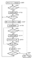
上記、図1の構成における処理のフローを表わすフローチャートを図8に示すが、説明を簡単にするため、簡略化した図3のフローチャートに従って先ず説明する。
【0033】
既に説明したように、本発明の画像処理装置100は、スキャナ等の入力部101から入力した1ページの画像データを所定のデータ量以下に圧縮符号化する装置である。該符号化処理を実現するために、前記入力部101以外に、符号化部102、再符号化部109、第1のメモリ104、第2のメモリ106等を有する。これらの機能ブロックを用い、図3に示すフローチャートに基づいて符号化処理を行なう。
【0034】
図3のフローチャートは、大別すると、下記の3つの処理フェーズに分かれる。
(1)符号化フェーズ
(2)符号化・再符号化フェーズ
(3)転送フェーズ
上記それぞれの処理フェーズおいて、どのように画像データ、符号化データ等が流れて処理され,メモリにどのように格納されるかを視覚的に解り易く示したのが図4乃至図7である。
【0035】
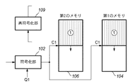
図4は、図3のフローチャートにおけるステップS303とS305に対応する符号化フェーズの初期状態を表わす。また、図5はステップS307〜S315に対応する符号化・再符号化フェーズの処理状態を、図6はステップS317に対応する転送フェーズの処理状態を、図7は転送フェーズ後の符号化フェーズの処理状態を表わす。以下、各フェーズについて説明する。
【0036】
<<符号化フェーズ>>
1ページ分の画像データの符号化処理は、符号化パラメータの初期設定(ステップS301)から始まる。ここでは符号化処理する画像サイズ(スキャナ等の入力部101から読み取る用紙サイズ)から一意的に定まる符号化データ量の上限値に基づき符号化部102に適用する量子化ステップQ1を設定する。
【0037】
そして、ステップS303にて、第1のカウンタ107は、実際の符号化処理(画像を8×8画素のブロック単位でJPEG圧縮)を行ない、出力される符号化データのデータ量を累積カウントする。
【0038】
次にステップS305にて、該データ量のカウント値が上記上限値をオーバーしたかどうかを検知し、オーバーしていなければステップS303のJPEG符号化処理を継続する。これが初期状態の符号化フェーズである。
【0039】
符号化部102から出力する符号化データは、図4に示すように第1のメモリ104と第2のメモリ106の両方に格納されていく。縦縞で示した領域が該格納した符号を表現している。
【0040】
<<符号化・再符号化フェーズ>>
符号化部102の符号化処理が進行し、前記データ量のカウント値が設定されている上限値をオーバーすると、ステップS307にて、第1のメモリ104内の符号化データを廃棄すると共に、ステップS309にて、符号化部102の量子化パラメータをQ2に変更する。
【0041】
符号化データのデータ量のカウント値が設定された上限値をオーバーするという事は、圧縮後のデータ量が目標値以内に収まらないことを意味する。よって同じ量子化ステップを用いて符号化処理を継続しても意味が無いので、前よりもデータ量が少なくなるように、Q1よりも量子化ステップ幅の大きい量子化ステップQ2に変更するわけである。
【0042】
量子化ステップ及び量子化演算内容を変更した後、ステップS311では符号化部102の符号化処理を再開し、図5に示すように符号化データを第2のメモリ106のみに格納する。それと並行して、ステップS313の再符号化処理を行なう。再符号化処理では、第2のメモリ106に格納済みの符号化データを読み出して、再符号化部109にて再符号化処理を行ない、前記2つのメモリ104、106に格納する。そして、縦縞▲1▼の符号を全て再符号化するまで、該符号化処理と再符号化処理を継続する。
【0043】
具体的にこの再符号化処理では、符号化データを一旦ハフマン復号した後の各量子化値に対して、これら値を2nで割った結果と同様の結果が出るビットシフト処理を施した後、再度ハフマン符号化を行なうことにより実現される(m=2の場合)。この方法は、ビットシフトのみで量子化ステップを変更する点と逆直交変換や再直交変換処理を行なわない点で、高速な再符号化処理が可能である。ステップ315では、再符号化処理の終了検知が行なわれる。
【0044】
再符号化後のデータ量は再符号化前の符号化データのデータ量よりも少なくなるので、図5に示すように、再符号化前の符号を格納していたメモリ領域に再符号化後の符号化データを上書きするように格納することができる。再符号化処理が終了した時点で、縦縞▲1▼の符号化データのデータ量は図6に示すの斜め縞▲1▼の符号化データのデータ量へと減少する。
【0045】
以上で説明したステップS307〜315が、符号化・再符号化フェーズで行なう処理である。
【0046】
<<転送フェーズ>>
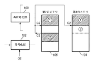
再符号化処理が終了したら、ステップS317では転送処理が行なわれる。該転送処理では、図6に示すように、符号化・再符号化フェーズで第2のメモリ106のみに格納した斜め縞▲2▼の符号化データを、第1のメモリ104内の斜め線▲1▼の符号化データに連結されるアドレスに転送し、格納する。その一方で、第2のメモリ106上で分散してしまっている斜め縞▲1▼の符号化データと斜め縞▲2▼の符号化データが第1のメモリ104上で連続して格納される様に、前記斜め縞▲2▼の符号化データを第2のメモリ106内で転送し、連結させる。これが、転送フェーズで行なう処理である。
【0047】
上記転送フェーズが終了したら、ステップS303、S305の符号化フェーズに戻り、図7に示すように斜め縞▲4▼の符号を符号化部102から出力して2つのメモリ104,106に格納する。この符号化フェーズは、初期状態の符号化フェーズ(図4)と少し異なり、符号化部102で符号化する際の量子化ステップがQ1からQ2に変更されていると共に、2つのメモリ104,106に格納されている符号化データも様々なフェーズで処理された符号の集まりである。それらの違いを無視すれば、転送フェーズ直後の符号化フェーズと初期状態の符号化フェーズは、同じと見なせる。
【0048】
よって、符号化フェーズ、符号化・再符号化フェーズと転送フェーズの3つを繰り返すことで、最終的に1ページの画像データを設定符号量以下に圧縮した符号を第1のメモリに格納することが出来る。しかも、入力部101は一連の処理が終わるまで、入力を継続するだけである。すなわち、画像を再度最初から入力し直すということが無くなる。
【0049】
図3に示したフローチャートは、説明が理解しやすいように、図4、図5、及び、図6に示した各フェーズに対応する処理のみを記述した。しかしながら実際には、1ページの画像データの入力はどこかのフェーズで終了する。従って、どのフェーズで終了したかによって、それ以降の対応も多少異なる。それを考慮した流れを示したのが図8のフローチャートである。図8のフローチャートは、1ページ分の画像データの入力完了と図3で説明した各種処理との関係を考慮したものであり、ここでは図3のフローチャートに、ステップS801、S803、S805、S807を追加している。
【0050】
ステップS801、S803、S805は、それぞれ、符号化フェーズ、符号化・再符号化フェーズ、転送フェーズにおいて、入力部101からの1ページ分の画像データの入力が終了したことを検知する。
【0051】
符号化フェーズと転送フェーズで1ページ分の画像データの入力が終了したことを検知した場合(ステップS801、S805)、ステップS807へ移り、当該ページの圧縮符号化処理を終了し、次に圧縮処理すべき画像データがあれば、次の1ページ分の画像データの圧縮符号化処理を開始し(各カウンタをリセットし、量子化パラメータを初期値に設定する)、無ければ停止状態に入る。
【0052】
一方、符号化・再符号化フェーズで1ページ分の画像データの入力終了を検知した場合(ステップS803)には、符号化部102では再符号化処理する画像データが無くなるまで一旦動作を止める必要があるので、ステップS311の符号化処理をパスし、ステップS313で、今までに符号化部102で符号化済みの画像データを所定の符号化データ量に抑える為の再符号化処理のみを継続して行なう。再符号化処理が全て終了して、その後の転送処理が終わらないと、1ページ分の画像データ全体の符号化データが第1のメモリ上に集まらないため、1ページ分の画像データの入力終了後も再符号化処理及びそれに続く転送処理は継続して行われる必要がある。この場合には、ステップS315にて、再符号化処理が全て終了したことを検知すると、符号化・再符号化フェーズ中に、第2のメモリ106のみに格納された符号化データを第1のメモリに転送し(ステップS317)た後、次のステップS805にて、1ページ分の画像データの入力終了が検知されてステップS807へ移ることになる。
【0053】
以上が動作であり、図8の動作説明でもある。
【0054】
<メモリ格納方法の変形例>
図9、図10は図5、図6の概念図で示したメモリ格納方法の変形例を示す図である。
【0055】
図5の概念図においては、符号化・再符号化フェーズでは、符号化部102から出力する符号化データは第2のメモリ106のみに格納していたが、図9に示すように符号化・再符号化フェーズ中に、符号化部102から出力する符号化データを第1、第2メモリの両方に直接格納する。
【0056】
符号化部102から見ると、どのフェーズで符号化して出力する符号化データも両方のメモリへ格納することになる。また、図6の概念図とは異なり、図10に示す様に、転送フェーズでメモリ間のデータ転送が必要なくなる。またこの変形例の場合には、符号化・再符号化フェーズにおいて、符号化データと再符号化データを第1のメモリ104へ送った順序で順次格納される。そのため2種類のデータが入り混じってしまうという問題は有る。
【0057】
従って、この変形例の場合にはこれに対応する為に符号化データをある単位で区切って、ファイル或いはパケットとして管理する様にする。具体的には、ファイル管理テーブル、或いは、パケット管理テーブル等を別に作成して管理する。
【0058】
一つの手法としては、符号化部102からのデータを第1メモリ104に格納する際、適当な単位(例えば前記直交変換の単位が8×8のブロックであるので、8×i(i=1、2…の整数)ライン分のデータ)毎に、画像データの先頭から管理番号を割り当て、各管理番号に対応する符号化データの格納先頭アドレスと該符号化データ量とを、管理番号順に格納できるような管理テーブルを作成する。
【0059】
符号化部102や再符号化部109は処理中のデータの管理番号を保持し、該管理番号に基づいて、符号化データ格納時の先頭アドレスと符号化データ量とを管理テーブルに書き込む。このようにすれば、符号化部102と再符号化部109で処理した符号化データをランダムに格納したとしても、前記管理テーブルを管理番号順にアクセスし、その時読み出させる先頭アドレスと符号化データ量に基づいて、符号化データを第1メモリ104から読み出せば、画像の先頭から順番に符号化データを読み出すことができる。このような管理機構を設ければ、画像上で連続するデータをメモリ上で連続するように格納する必要性が無くなる。
【0060】
図10の概念図における転送フェーズ後の符号化フェーズは、これまで説明した2つの符号化フェーズ(図4、図7)とほとんど同じであり、第1のメモリ内における符号の格納状態が図11に示した様に若干異なるだけである。よって、先の説明と本変形例は、3つのフェーズを繰り返して処理することに変わりは無い。
【0061】
<第2の例>
次に、本発明において特徴的な符号化処理を行なう為の、第2の例(これまで説明した構成を第1の例という)を図2を用いて説明する。
【0062】
図2は、第2の例における画像処理装置200のブロック構成図である。
【0063】
図1の第1の例における画像処理装置100と大きく異なる点は、最初に符号化を行なう符号化部が2つ並列に存在する点である。画像処理装置200は、入力部201から入力される画像データを、第1の符号化部202と第2の符号化部205で並行して符号化し、互いに圧縮率の異なる2種類の符号化データを生成する。本第2の例でも、符号化方式は公知のJPEG符号化方式を用い、8×8画素のブロック単位で画像データをDCT変換し、後述する量子化ステップを用いた量子化、ハフマン符号化処理を行なうものである。
【0064】
なお、本例では第1の符号化部202よりも、第2の符号化部205の方が適用する圧縮率を高く設定する場合について説明する。具体的には、第1の符号化部202における量子化パラメータをQ1、第2の符号化部205の量子化パラメータをQ2(Q2の量子化ステップは、Q1の量子化ステップより大きい)とする。
【0065】
符号化部202から出力される符号化データは、第1のメモリ制御部203を経由して、第1のメモリ204に格納される。このとき、第1のカウンタ208は、符号化部202から出力される符号化データのデータ量をカウントし、これを保持すると共に、符号化シーケンス制御部209にも出力する。
【0066】
一方、符号化部205で符号化された符号化データは、第2のメモリ制御部206を経由して、第2のメモリ207に格納される。このとき、第2のカウンタ210は、符号化部205から出力される符号化データのデータ量をカウントし、これを保持する。更に、後述する第2のメモリ207に格納している符号化データを第1のメモリ204に転送する時には、それと同時に上記第2のカウンタ210のカウント値を、第1のカウンタ208に転送する。
【0067】
さて、第1のカウンタ208が符号化部202から出力される符号化データのデータ量をカウント中に、該カウント値がある設定値に達した時には、符号化シーケンス制御部209は、第1の例と同様、メモリ制御部203に対して第1のメモリ204に格納されているデータを廃棄するよう制御信号を出す。
【0068】
そして、符号化シーケンス制御部209は、第2のメモリ207に格納済みの符号化データを読み出して第1のメモリ204に転送し、第1のメモリ204に格納するよう、メモリ制御部206とメモリ制御部203に制御信号を出力する。この結果、第2のカウンタ210のカウント値が第1のカウンタ208に転送され、その値が第1のカウンタのカウント値としてロード(上書き)される。
【0069】
要するに、上記第2のカウンタ210のカウント値は、第2のメモリ207に格納している符号化データのデータ量を表わしているので、そのカウント値と対応する符号化データを、そのまま第1のカウンタと第1のメモリへコピーしたと考えれば良い。
【0070】
さらに、符号化シーケンス制御209は、第2の符号化部205に対して、今までよりも、符号化データが少なくなるような符号化を行なうように制御信号を出す。一方、第1の符号化部202に対しては、その直前までの第2の符号化部205における量子化パラメータQ2を継承するよう設定を変更する。
【0071】
例えば、第2の符号化部205における量子化ステップを2倍に切り替える。この結果、第1の符号化部202は、第2の符号化部205は更に大きな量子化ステップQ3を用いて、次のオーバーフローに備えた更に高い圧縮率の符号化処理を行うことになる。切り替えられた各符号化部202、205から出力された符号化データは、それぞれ、対応するメモリ制御部203、206を経由して、対応するメモリ204、207に格納される。
【0072】
ここでは、量子化ステップの倍率比を2倍としたがこれに限らず、任意に設定できることは示すまでもない。例えば、カラー画像の場合、色変換した際に生成される1つの輝度信号(輝度データ)と、2つの色差信号(色差データ)に対して別々の量子化ステップを割り当て、片方ずつ交互に2倍にするようにすることで、より細かな設定が可能となる。
【0073】
そして、符号化シーケンス制御209は、メモリ制御部206に対し、既に第2のメモリ207内に格納している符号化データを読み出して、再符号化部211にデータを送るよう制御信号を出す。再符号化部211は、図1の再符号化部109と同様にして符号化データの再符号化処理を行なう。
【0074】
第3のカウンタ212は、再符号化部211が出力したデータ量をカウントするもので、再符号化処理を開始する直前にゼロにリセットされ、再符号化処理中の出力データ量をカウントする。このカウンタ212は、再符号化処理が終了した時点で、そこで得られたカウント値を第2のカウンタ210に転送する。
【0075】
第2のカウンタ210は、上記転送されてきたデータ量カウント値を、第2のカウンタ210内に保持しているカウンタ値に加算することにより、再符号化処理中にメモリ207に格納した、符号化データと再符号化データの合計のデータ量を算出する。即ち、メモリ207に格納しているデータ量とカウンタ210のカウント値とが一致する。
【0076】
再符号化処理の終了/未終了に関わらず、符号化するべき入力部201からの画像データが残っていれば、2つの符号化部202と205による符号化処理を継続して行なう。そして、カウンタ208のカウント値がある設定値に達したかどうかの監視は入力部201から入力される1ページ分の画像データの符号化処理(符号化、再符号化)が終わるまで繰り返され、上述した符号化と再符号化の処理は、ここで得られる検出結果に応じた制御の上で実行される。
【0077】
上記動作を簡単にまとめると、第2の符号化部205は、第1の符号化部202よりも1つ上の圧縮率での符号化を行う。そして、第1の符号化部202で生成された符号量が設定量に達した場合、第1の符号化部202の量子化パラメータを、直前の第2の符号化部205と同じにする。また、第2の符号化部205の量子化パラメータを更に高い圧縮率となるよう設定する。そして、第1のメモリ204内のデータを破棄し、第2のメモリ207に格納されていたデータを第1のメモリ204に転送すると共に、第2のカウンタ210の値を第1のカウンタ208に書き込む。そして、第2のメモリ内のデータを更に高い圧縮率で再符号化させるため、再符号化部211に対して、第2の符号化部205に新に設定した量子化パラメータと同じにする。この結果、第2のメモリ207内のデータは、ページの先頭から新たなに設定された量子化パラメータで圧縮したのと等価の符号データが格納されることになる。
【0078】
図2で説明したように符号化部が2つある場合は、図12に示すフローチャートに基づいて1ページ分の画像データの符号化を行なうことになる。なお、図12の説明は、符号化部が1つの場合のフローチャートである図8とは、大半は類似しており、当業者であれば上記説明から本第2の例の特徴は十分に理解できるであろうから、符号化部1つの場合と同じように3つのフェーズで処理を説明する様にし、図8と異なる点を主に説明することとする。
【0079】
上述した図8のフローと本例のフローとの一番大きな違いは、ステップS317の転送処理が、ステップS307とステップS309の間に移動していることである。要するに、符号化・再符号化フェーズと転送フェーズが入れ替わったと見なせば良い(ステップS307の符号化データの廃棄処理は例外である)。
【0080】
ステップS301の符号化パラメータの初期設定では、第1の符号化部202に量子化パラメータQ1を、第2の符号化部205には量子化パラメータQ2を設定する。ただし、量子化パラメータQ2で表される量子化ステップは、Q1よりも大きい。
【0081】
符号化フェーズでは、ステップS801、S303、S305を繰り返し実行する。ステップS801とステップS305は符号化部が1つの場合と同じ処理であるが、ステップS303の符号化処理だけは図13に示すように異なっている。
【0082】
第1のメモリ204へ格納する符号化データは圧縮率が段階的に高くなるようにするため、最初に格納する符号化データは圧縮率が一番低い量子化パラメータQ1で符号化したデータを格納し、第2のメモリへ格納する符号化データは量子化パラメータQ2で符号化したデータを格納する。
【0083】
第1のメモリ204へ格納中のデータ量が設定されている上限値をオーバーしたら(ステップS305)、直ちに、第1のメモリ204で保持していた符号化データを廃棄し(ステップS307)、第2のメモリ207で保持している圧縮率の高い符号化データを、第1のメモリ204へ転送する(ステップS317、図14参照)。これにより、第1の例で説明した1回目の再符号化処理の終了を待たずに、速やかに、上限値をオーバーしない適切な2番目の候補の符号化データを第1のメモリ207内に格納出来る。これが、図1に対する、2つの符号器を持つ図2を適用することの最大の利点である。
【0084】
本第2の例では、2つのメモリ204、207で同じ圧縮率の符号化データを持っていることが無駄という考え方なので、第2のメモリ207には、第1のメモリ204に格納する符号化データよりも圧縮率の高い符号化データを格納しておくようにしている。従って、それ以降の処理もこの考え方に基づき行われるものであり、第2のメモリ207内の符号化データを第1のメモリ204に転送する処理(転送フェーズ)が終了した後は、第2のメモリ207の符号化データを、更に1段階圧縮率の高い符号化データを保持する様に再符号化することとなる。
【0085】
具体的には、まず図15に示す様に、転送フェーズの次の符号化・再符号化フェーズでは、上記再符号化の前に、2つの符号化部202,205に適用される各量子化パラメータQ1、Q2をそれぞれQ2、Q3へ変更し(ステップS309)、1ページの画像データの入力が終了せずに続いていれば(ステップS803)、後続の画像データは新たな量子化ステップが設定された2つの符号化部で該入力データを符号化して(ステップS311)、対応する各メモリ204,207へ格納する。そして、上記符号化処理と並行して第2のメモリに格納されている符号化データ(第1のメモリ204に転送したもの)は、第1のメモリ内の符号化データよりも1段階高い圧縮率の符号化データに変更するべく、再符号化部211にて量子化パラメータQ3を用いて符号化されたデータが得られる様な再符号化処理(S313)を行ない、再符号化データを第2のメモリ207に格納し直す。
【0086】
なお、本第2の例でも、第1の例と同様、再符号化処理では、符号化データを一旦ハフマン復号した後の各量子化値に対して、これら値を2nで割った結果と同様の結果が出るビットシフト処理を施した後、再度ハフマン符号化を行なうことにより実現される。この方法は、ビットシフトのみで量子化ステップを変更する点と逆直交変換や再直交変換処理を行わない点で、高速な再符号化処理が可能である。
【0087】
また、本第2の例の様に符号化部が2つ有る場合には、図15に示したように、第2のメモリ207に符号化データと再符号化データを混在して格納する状況が発生する。従って、前述したように、符号化データをある単位で区切って、ファイル或いはパケットとして管理することが、第2のメモリ207に対しても必要になる。その為には、例えば第1の例における変形例と同様の構成を設ければ良いであろう。
【0088】
図12において、再符号化処理の終了をステップS315で検知したら、また符号化フェーズ(ステップS801、S303)に移行する。なお、符号化・再符号化フェーズ後の符号化フェーズでは、図16に示すように、2つのメモリ204,207が保持する符号化データは圧縮率が違うだけでなく、符号化データの混在の仕方(アドレス)もかなり違ってくる。従って、再度、第1のメモリ204のデータ量が設定値をオーバーした場合には、第2のメモリ207で保持されている符号化データ(▲6▼+▲8▼の横縞の領域の符号)を第1のメモリ204へ転送する必要が出てくる。これらを考慮すると、第2のメモリ207だけでなく、第1のメモリ204でも符号化データをファイル或いはパケットとして管理する必要がある。よって、第1のメモリ204にも前述の管理テーブルを用いた管理機構が必要となる。
【0089】
図16に示された符号化フェーズの状態は、量子化パラメータと符号化データの混在の仕方が、再符号化処理の前後で異なっていること以外は、初期状態の符号化フェーズ(図13)と同じである。よって、符号化フェーズ、転送フェーズと符号化・再符号化フェーズを繰り返すことで、最終的に、1ページ分の画像データを設定した上限値以下に圧縮した符号化データを確実に第1のメモリ204に格納することが出来る。
【0090】
なお、第1の例に対し、転送フェーズと符号化・再符号化フェーズの配置順が逆であることから、図8において転送処理後に行なっていた1ページ分の画像データの入力終了検知(ステップS805)は、符号化・再符号化フェーズで行なう1ページ分の画像データの入力終了検知(ステップS803)と、ほとんど同じタイミングになってしまう。また、2つの検知処理は、機能的にはステップS805と同じで、タイミング的にはステップS803と同じである、従って、これら2つのステップは、新たな1ページ分の画像データの入力終了を検知するステップとして統合し、ステップS1201と表記しておく。
【0091】
以上説明した第1、第2の例では、第1のメモリと第2のメモリは物理的に別のメモリであるとして説明をしてきた。これは、2つのメモリに対するアクセスが独立している方が有利なためである。しかしながら、第1のメモリと第2のメモリを、物理的に別のメモリとしない場合も本発明の範疇に含まれる。物理的に1つのメモリ上に、前記第1のメモリと第2のメモリに相当する2つの領域を確保して、第1のメモリを第1のメモリ領域、第2のメモリを第2のメモリ領域と言い直して、これまでの説明を読み直せば、本発明は、1つのメモリでも実現できることが分かる。
【0092】
また、1つのメモリで上記各例を実現する場合には、前記転送フェーズで説明したデータ転送処理のいくつかは不要となる。その詳細はその都度容易に想像できるので説明は省略するが、前記2つの領域を厳密に別けて使用する場合、物理的に2つのメモリを持つ時と同じようにデータ転送処理が必要であるが、2つの領域間で同じデータを共有することになれば、データ転送処理が不要になるだけでなく記憶容量の削減も図れる。
【0093】
例えば、第2のメモリ領域で保持していた符号化データを、第1のメモリ領域へ転送する際、該符号化データが格納されている先頭アドレスとデータサイズの2つの情報を第2のメモリ制御部から第1のメモリ制御部へ転送するだけで、前記符号化データを転送したのと同じ効果が得られる。
【0094】
前記符号化データを、ファイル形式やパケット形式で格納している場合は、メモリ制御部の間で転送する情報は少し増え、該符号化データに関連する管理テーブル情報を転送する必要がある。それでも、符号化データを転送するよりは、効率が良い。
【0095】
<第3の例(第1の例に像域情報の圧縮機能を追加した例)>
前記第1、第2の例では、画像データをJPEG方式で符号化して、該JPEG符号のみを格納するものである。これと並列に像域情報の可逆符号化も行ない、該可逆符号も格納するようにした画像処理装置の構成を図17に示す。同図は図1に示した基本構成に像域情報の処理系を追加したもので、以下で説明を行なう。但し、図1の構成と同じ機能ブロックには、同一番号を付し説明を省略する。
【0096】
イメージスキャナやページ記述言語レンダリングなどから入力部101を通して入力した画像データは、既に説明した処理方法に基づいて符号化と再符号化処理を繰り返して行ない、符号化データを設定した符号量以内に収める。
【0097】
一方で、該画像データを像域情報生成部1701に送り、前述の像域情報を生成する。スキャナ入力画像の場合、該画像データのみに基づいて像域情報を生成するが、ページ記述言語(PDL)を展開・描画した画像の場合、該PDL情報も参照して像域情報を生成する。なお、像域情報はスキャナ等の画像入力機器で生成することもある。その場合、前記像域情報も入力部101を通して入力され、像域情報生成部1701を素通りして、次のユニットへ送られる。
【0098】
ただし、実施形態では説明を簡単なものとするため、像域情報は、各画素毎に、有彩色/無彩色の区別する1ビット、文字線画/中間調画像を区別する1ビットの計2ビットとする。有彩色/無彩色の区別は、入力した画像データがRGB形式のデータであれば、各色成分の値が互いに実質的に等しい場合に無彩色、それ以外の場合には有彩色として判定する。また、注目画素の濃度(或いは輝度)が隣接する画素に対して急峻に変化している(予め設定した閾値以上に変化している)場合には、文字線画のエッジであると判断し、変化がなだらかであれば中間調画像として判断することで実現できるであろう。像域情報の取り得るデータはバイナリ表現で00、01、10、11(10進数では0〜3)の4通りとなる。
【0099】
生成した像域情報は、ブロック化ユニット1703にて、符号化部102において画像データをまとめて符号化するデータのサイズと同じサイズ(第1の例では8×8であったので、8×8サイズとなる)へブロック化する。
【0100】
画像データの圧縮に利用するJPEGのような多値の圧縮は、2値データの集まりである像域情報の圧縮に使うには非効率である上に非可逆圧縮である。像域情報の圧縮には可逆圧縮であるJBIG、或いはPackBits等のランレングス符号化を用い、可逆符号化部1705にて像域情報を可逆符号化する。
【0101】
符号化した像域情報は、第1のメモリ制御部103を経由して第1のメモリ104に格納し、同じデータをメモリ制御部105を経由して第2のメモリ106にも格納する。それと同時に、前記可逆符号化部から出力する符号量を第4のカウンタ1707にてカウントし、該カウント値を可逆符号化制御部1709に送る。
【0102】
可逆符号化制御部1709内のレジスタには目標値が設定され、前記符号量が該目標値をオーバーした時に、第1のメモリ104に格納済みの符号化データ(像域情報の符号化データ)を廃棄するよう第1のメモリ制御部103に制御信号を出力する。廃棄の仕方は前記画像データの符号化データを廃棄する方法と同じである。続いて、第2のメモリ106から符号化した像域データを読み出し、該データを可逆符号再符号化部1711に送るよう、該可逆符号化制御部1709は第2のメモリ制御部105へ制御信号を出力する。
【0103】
すなわち、符号化部102や再符号化部109が符号化シーケンス部108からの指示情報(圧縮パラメータ)に従って圧縮処理を行うのと同様、この可逆符号化1705、可逆符号再符号化部1711も、可逆符号化制御部1709からの圧縮パラメータ(圧縮率を決定するパラメータ)に従って像域情報を圧縮することになる。
【0104】
可逆符号再符号化部1709は、符号化データを受け取るとそれを復号化し、複数の属性フラグデータの一部を廃棄するか固定値に置き換えた後、再び可逆符号化を行なう。後に説明するが、属性フラグの一部を固定値に置き換えた場合でも情報エントロピーが低下するため、ランレングス符号化後のデータ量は減少する。再符号化後の属性データは、第2のメモリ106に再び格納すると共に、第1のメモリ104にも格納する。そして、再符号化後の符号量を第5のカウンタ1713にてカウントする。
【0105】
一方、可逆符号化制御部1709は、可逆符号再符号部1711において情報量を減らした属性フラグデータと、同じ情報エントロピーの属性フラグデータを符号化するよう、可逆符号化部1705が備えた像域情報変換処理部に対して属性フラグの一部を廃棄、或いは固定値に置き換えるよう制御信号を送り、符号化処理を継続させる。但し符号化データは第2のメモリのみに格納する。それと同時に、第4のカウンタ1711にも制御信号を送り、それまでカウントして保持していた値をリセットさせ、像域情報変換処理の内容が変更になった後に符号化処理して生成する符号量を新たにカウントさせる。
【0106】
前記再符号化する像域情報の符号化データが無くなり再符号化処理が終了したら、前記第2のメモリのみに格納した符号化データを第1のメモリにも転送して格納する。それと共に、第5のカウンタ1713の計数値を第4のカウンタ1707に転送して加算する。それによって、カウンタ1711には、像域情報変換処理の内容が変更になった後の可逆符号化データの全符号量が計数され、それに対応する符号化データは第1及び第2のメモリ各々に格納された状態となる。この状態は初期の可逆符号化処理のみをしている時とほとんど同じである。よって、これ以降は、可逆符号化部1705が出力する符号化データを第1及び第2の両方のメモリに格納して、可逆符号化処理をしている最初の状態と同じ状態に戻り、引き続き符号量の監視が行なわれる。
【0107】
第4のカウンタの計数値が、符号化制御部1709内のレジスタに設定された目標値をオーバーするたびに、廃棄、或いは固定値に置き換える属性フラグを増やすことで、像域データの符号量を段階的に減らすことができ、該像域データの符号量を目標値以内に収めることが可能となる。
【0108】
次に、図17の画像処理装置の処理内容を表わすフローチャートを図18に示し、該フローチャートを用いて説明を行なう。該画像処理装置の処理は、上述したように、図1の構成における画像データの符号量の制御方法と基本的に同じであり、個別の処理の内容が少しずつ異なるだけである。以下に相違点を列挙する。
(1)符号化処理と可逆符号化処理
(2)量子化ステップ変更と像域情報変換処理の変更
(3)再符号化処理と可逆符号再符号化処理
上記処理の相違を、前記図8のフローチャートに反映させたものが図18のフローチャートである。図8におけるステップS303、S309、S311、S313の処理を、図18ではステップS1703、S1709、S1711、S1713の処理に置き換えている。符号化パラメータの初期設定では、画像サイズによって決まる可逆符号化データ量の上限値を可逆符号化制御部内のレジスタにセットし、上記像域情報変換処理の内容を初期状態にリセットする。あとは、図8のフローチャートと同じ説明になる。
【0109】
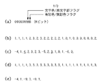
次に、1画素あたり2ビットの像域情報に6ビットデータ“000000”を付加して8ビット化(一般に、コンピュータでは8ビットで処理が効率が良いため)した後、可逆符号としてPackbits符号化を行なった場合の、具体的な処理内容を、図19を用いてさらに詳しく説明する。
【0110】
Packbits符号化する前の8ビットデータは、図19(a)に示すように上位6ビットは全て0で、下位2ビットの上位側に、対応する画素データが文字部かそうでないかを表わすフラグ、下位側には有彩色か無彩色を表わすフラグデータが入っているものとする。よって、該8ビットデータが取り得る値は、0以上3以下の値である。なお、像域の特性は上記のように各ビットが0、1のいずれかで決定され、フラグとしての性格を持つので、以下では、像域情報を像域フラグもしくは像域フラグデータと表現することとする。
【0111】
像域情報生成部1701からは、上記8ビットのデータが画素単位で出力されるものとする。具体的な出力データとして、図19(b)に示すデータを考える。
【0112】
これをPackbits符号化すると図19(c)に示すデータに圧縮される。圧縮後のデータで負の値は連続するデータの個数を表わし、非連続データの個数は正の値で表わしている。これらは長さ情報と言うもので、該長さ情報のサインビットから連続データが続くのか、非連続データが続くのかを判別することが出来るようになっている。圧縮後の各データは同図(b)と同じく8ビット(1バイト)である。1バイトの長さ情報で、表わすことができる最大値は255の半分の約128であり、長さ情報がそれ以下の場合は1組の長さ情報とそれに続く像域フラグデータ群で符号化でき、それを超える場合は複数の組の、長さ情報+像域フラグデータ群、に分けて符号化される。
【0113】
図19(c)の圧縮データを詳しく見てみることにする。最初の長さ情報“−4”はマイナスの値なので、上述したように連続データの連続個数を表わし、長さ情報直後の像域フラグデータ“1”が4つ続くことを表わしている。
【0114】
次のデータ“4”はまた長さ情報であるが、今度はプラスの値なので非連続データが4つ続くことを示している。よって、前記“4”に続く4つのデータ“2,3,2,3”が非連続データを表わす。図19(c)では、長さ情報と像域フラグデータとが区別し易いように、プラスの長さ情報のみ下線を引いている。
【0115】
上記非連続データの次の“−5”は又、連続データの長さ情報で、該長さ情報直後の像域フラグデータ“2”が5つ続くことを表わしている。次の下線付きのデータ“3”は非連続データの長さ情報で、後続する3つのデータ“1,0,1”が像域フラグデータであり、さらに次の“−6,0”は、像域フラグデータ“0”が6個連続することを示している。
【0116】
上記圧縮データを可逆符号再符号化部1715で再符号化処理(設定した目標値に達しいた場合に実行されるものである)するとどのようになるのかを、図19(d)(e)を用いて説明する。ここでは、再符号化処理において、有彩色・無彩色フラグを“1”に固定してすべて有彩色にする。
【0117】
符号化された像域データは一旦復号され、図19(b)のデータに戻された後、上記フラグデータの置き換えが行なわれ、図19(d)のデータに変換される。そして、変換されたデータを再びPackbits符号化することによって、図19(e)の符号化データが得られる。再符号化前の15バイトの符号化データが再符号化後には6バイトに減少することが解かる。
【0118】
上記の再符号化処理を行なったにもかかわらず、全符号量の計数値が符号化制御部1713内のレジスタに設定された目標値を再びオーバーした場合には、前記再符号化処理が終了していれば、直ちに次の新たな再符号化処理を開始する。前記再符号化処理が終了していなければ、該再符号化処理が終了後、直ちに次の新たな再符号化処理を開始する。
【0119】
新たな再符号化処理では、残りの1ビットの像域フラグも“1”(中間調を示すことになる)に置き換える。これにより、すべての像域フラグデータ(8ビット)の値は“3”となり、データのバイト数をNとすると、符号化後のデータ量はおよそ(2N/128)+2バイトとなる。
【0120】
これは、連続データの個数が128個を超えるたびに、あらたな2バイト1組の符号化データ(長さ情報と連続データ)が増えるためである。
【0121】
Packbitsの符号化回路や復号回路それにデータ変換回路はそれぞれ公知の技術であり、個別の回路構成についての説明は省略する。
【0122】
上記説明では簡単化のため、各画素の像域フラグを2ビットとして説明したが、前述したように像域フラグとして他の情報もいくつかある。上記再符号化処理では、2ビットの像域フラグデータでは最大2回の再符号化、4ビットの像域フラグデータでは最大4回の再符号化処理が可能であり、像域フラグのビット数が多い程、再符号化処理の回数を増やすことができ、符号量を多段階で制御することができる。
【0123】
さらに、状態数を縮退させる方法を用いれば、さらに符号量を多段階で制御することができる。例えば、2ビットの像域フラグでは、4状態を表わすことができるが、これを1回目の再符号化処理で3状態に縮退させ、2回目の再符号化処理で2状態に縮退させることで、符号化前の情報エントロピーを少しずつ減らし、符号化後のデータ量(符号量)を細かく減らしていくものである。
【0124】
上述したフラグデータを1ビットずつ固定値に置き換える処理を、状態数という言葉を用いて表現すると、像域フラグデータを再符号化するごとに状態数を半分に減らす、と言うことが出来る。
【0125】
1回の再符号化処理で、状態数を半分に減らすより、状態数を1つずつ減らした方が、符号量を細かく減らせるのは当然である。
【0126】
状態数を1つずつ減らした場合の処理結果を図20(b)(c)(d)(e)に示し、それについて説明する。図20(a)は、図19(b)に示した像域フラグデータと同じ、2ビットの4状態の全てが存在するデータである。該4状態をあらためて列挙すると、以下のようになる。
(1)有彩色の文字部(データ“3”に対応)
(2)無彩色の文字部(データ“2”に対応)
(3)有彩色の非文字部(データ“1”に対応、有彩色の画像部とも言う)
(4)無彩色の非文字部(データ“0”に対応、無彩色の画像部とも言う)
1回目の再符号化処理で、上記4状態の内、(3)有彩色の非文字部と(4)無彩色の非文字部、の2状態を合体して1つの状態(3')非文字部に縮退させる。これにより、以下の3つの状態となる。
(1)有彩色の文字部
(2)無彩色の文字部、
(3')非文字部
具体的には、データ“0”を“1”に置き換えることで、上記状態の縮退を行なう。状態縮退後のデータは図20(b)に示すデータに変わる。これをPackbits符号化すると図20(c)に示す符号化データになる。再符号化前の符号化データ図19(c)よりも多少符号量が少なくなっていることが解かる。
【0127】
2回目の再符号化処理では、(1)有彩色の文字部と(2)無彩色の文字部、の2状態を合体して1つの状態(1')文字部に縮退させる。これにより、以下の2状態となる。
(1')文字部
(3')非文字部
今度は、データ“2”を“3”に置き換えることで、上記状態の縮退を行なう。状態縮退後のデータは図20(d)に示すデータに変わる。このデータは図19(d)のデータと同じである。これをPackbits符号化した符号化データ図20(e)は当然図19(e)と同じ符号化データになる。
【0128】
状態数を1つずつ減らした場合、再符号化前の15バイトのデータが1回目の再符号化で11バイトに減少し、2回目の再符号化でやっと6バイトに減少する。このように細かく変化して減少する符号量を得ることが出来るので、目標符号量に近い像域フラグの圧縮データを得ることができる。
【0129】
上述したように像域フラグデータの可逆符号化処理は、画像データの圧縮符号化処理とは独立に制御され、それぞれに目標符号量以内のデータに収められる。
符号化された2種類のデータは、外部に接続されるネットワーク機器、画像出力装置や大容量記憶装置等へ出力する際に多重化する。該多重化を考慮して、前記2種類のデータを符号化処理する単位を、前述したように同じサイズに合わせておき、1単位を符号化して生成される符号化データを1つのパケットあるいはファイルとして管理・格納する。多重化する際に、画像位置が同じ2種類のパケットデータを、例えば画像データ・像域データの順に連結して、1パケット化し、外部へ出力する。
【0130】
<第4の例(第2の例に像域情報の圧縮機能を追加した例)>
前記例2に対して、画像データの符号化処理と並列に像域情報の可逆符号化も行ない、該可逆符号も格納するようにしたものが図21に画像処理装置である。同図は図2に示した基本構成に像域情報の処理系を追加したもので、以下で説明を行なう。但し、同図には図2及び図17で用いた機能ブロックを使用しており、該ブロックには同一番号を付し説明を省略する。
【0131】
図21の画像処理装置では、図2の構成における画像データの圧縮符号化処理と同じように、2つの符号化部で情報エントロピーの異なる2種類の像域情報を可逆符号化する。該2つの符号化部とは第1の可逆符号化部1705と第2の可逆符号化部2106である。ここで追加する第2の可逆変換部2106では、第1の可逆符号化部よりもエントロピーの下げた像域情報を符号化する。
【0132】
その他の追加ブロックは、上記第2の可逆変換部2106が出力する符号量をカウントする第6のカウンタ2108のみである。
【0133】
図21において、画像データを圧縮符号化するブロックと像域情報を可逆符号化するブロックとは以下のような対応関係がある。
(1)第1、第2の符号化部と第1、第2の可逆符号化部
(2)第1、第2、第3のカウンタと第4、第6、第5のカウンタ
(3)再符号化部と可逆符号再符号化部
(4)符号化シーケンス制御部と可逆符号化制御部
上記各項目の前者のブロックを用いて画像データを圧縮符号化し、後者のブロックを用いて像域情報を可逆符号化する。2つの符号化処理は、ほとんど同じ方法で独立に制御され、各々のデータを目標符号量以下に圧縮する。
【0134】
画像データは量子化ステップの変更により段階的に符号量を減らしていくが、像域情報の方は、可逆符号化前の像域情報のフラグデータの状態数を減少させてエントロピーを下げることで、可逆符号化後の符号量を減らしていく。
【0135】
初期状態では、第1の可逆符号化部1705は画素毎の全像域情報を符号化するが、第2の可逆符号化部2106は該像域情報のフラグデータの状態数を前述した像域情報変換処理によって減らしてから可逆符号化を行なう。
【0136】
第1の可逆符号化部から出力した符号量が目標値をオーバーした(もしくは目標値に達した)ところで、第1のメモリ104に格納していた可逆符号を廃棄して、第2のメモリ106に格納していた可逆符号を第1のメモリに転送し、前記第2の可逆符号化部で行なっていた像域情報変換処理を第1の可逆符号化で引き継いで、前記第1のメモリに転送した可逆符号の後に符号化データを格納する。
【0137】
第2の可逆符号化部では、これまでよりもさらに前記フラグデータの状態数を減らすような像域情報変換処理を行ない、それを可逆符号化する。そうすることで、第1の可逆符号化部より、符号量が少ない可逆符号を生成して第2のメモリに格納する。
【0138】
すでに第2の可逆符号化部で符号化済みの第2のメモリ内の可逆符号、すなわち第1のメモリにも転送した可逆符号は、可逆符号再符号化部1711にて復号化し、第2の可逆符号化部で行なう像域情報変換処理と同じ状態数となるように可逆符号再符号化部にて像域情報変換処理し、再び可逆符号化して、第2のメモリに書き戻す。このように、図21に示す構成においても、画像データの圧縮符号化処理と同様の方法で、像域情報の符号化処理を行ない、該符号量を制御することが出来る。
【0139】
よって、上述した処理のフローチャートは、図12に示す画像データを圧縮符号化処理するフローチャートの一部の表現を変えるだけで、そのまま用いることが出来る。変える部分は図8のフローチャートから図18のフローチャートの変更と同様、以下の3点である。
(1)符号化処理 → 可逆符号化処理
(2)量子化ステップ変更 → 像域情報変換処理の変更
(3)再符号化処理 → 可逆符号再符号化処理
上記3点の表現を変えたフローチャートを図22に示す。ステップS2103、S2109、S2111、S2113の4つの処理内容が上記のように変わる。
【0140】
画像データの圧縮符号化処理と像域情報の符号化処理は並列に行ない、且つ独立に制御するので、図21に示す画像処理装置は、図12と図22の2つのフローチャートによって処理フローを規定することが出来る。
【0141】
<第1の実施形態>
以上本発明の実施形態の前提となる例を説明した。本第1の実施形態では、上記第3の例、第4の例に対して、先に示した解決すべき課題を克服するための構成と制御方法を提供する。説明を簡単なものとするため、ここで、図21の構成(第4の例)に対するものとして説明する。ただし、第3の例に適用できるのは、当業者であれば、以下の説明からすれば容易に想到し得よう。
【0142】
図21では、画像データ及び像域情報の各々の符号量が、各々の設定符号量以下になるよう、符号化シーケンス制御部と可逆符号化制御部で各々独立に符号量を制御していた。そのため、各々の制御を確実に行なえば、トータルの符号量も2つの設定符号量の和以内に確実に収まる。
【0143】
ただし、一方の符号量が大幅に少ないとき、全体の符号量としては過剰圧縮の状態となる。一方の符号量が設定符号量より確実に少なくなる時、その残りの符号格納メモリを有効に利用するには、2つの符号量を見て、総合的に制御する必要がある。
【0144】
そのため、本第1の実施形態では、図23に示すように、非可逆符号化した符号量と可逆符号化した両方の符号量を符号化シーケンス制御部209へ入力する。
【0145】
本第1の実施形態の符号化処理フローは、前記図12に示したフローチャートの一部(S305,S307,S309,S317)を図24のフローチャートに置き換えたものとなる。但し、ステップS303とS311の符号化処理は、可逆符号化と非可逆符号化の両方を並列に行なうものとする。
【0146】
ステップS2401にて入力された画像情報を符号化した2種類の符号量(第1の符号化部202での符号量、第1の可逆符号化部1705による符号量)の総和Wを計算する。
【0147】
ステップS2403にて前記総和Wを全符号量の上限として設定された設定符号量Tと比較する。
【0148】
ステップS2405にて非可逆符号量(画像データの符号量)を前記総和で割って全符号量に対する非可逆符号量の割合Rを求める。次いで、ステップS2407にて該割合を設定符号比率Pと比較する。設定符号比率Pとは全符号量に対する非可逆符号量の比率の基準値となる閾値である。
【0149】
2種類の符号で符号格納メモリを有効に利用するために、ステップS2401にて該2種類の符号の総和Wを計算し、該総和Wが設定符号量Tを越えていないかどうかをステップS2403で検出する。どちらか一方の符号量が対応する設定符号量を超えていても、総和Wが設定符号量Tを超えなければ、そのままの状態で符号化処理を継続する。よって、W>Tでなければ、S2405〜S2415をパスしてS2417へ進み、次のブロックの符号化処理を行なう。
【0150】
しかし、総和Wが設定符号量Tを超えた場合、少なくとも一方の符号を再符号化処理しなければ、全体の符号量が設定符号量T以内に収まらない。そこで、どちらの符号を再符号化処理するのかを決めるために、ステップS2405にて全符号量に対する非可逆符号量の割合Rを計算し、ステップS2407にて該割合Rを設定符号比率Pと比較する。
【0151】
該割合Rが設定符号比率Pより大きい場合、非可逆符号(JPEG)の符号量が基準よりも多いことになるので、ステップS2409へ移り、非可逆符号の再符号化処理を起動するよう制御する。逆の場合にはステップS2411へ移り、可逆符号(Packbits)の再符号化処理を起動するよう制御する。
【0152】
いずれの場合も、再符号化処理後の符号と同じ圧縮率(設定)の符号へと未圧縮画像情報を符号化するため、ステップS2413またはステップS2415にて、対応する符号化部の圧縮条件等を更新した後、図12におけるS311の符号化処理とS313の再符号化処理等から成るループ処理に移る。上記各種判定処理は符号化シーケンス制御部209にて行ない、ここから、4つの符号化部と2つのメモリ制御部の制御を行なう。
【0153】
以上説明したように、2種類の符号を各々独立に再符号化処理するのではなく、設定した比率よりも符号量の多い方を、全符号量Wが設定符号量Tを超えた時点で再符号化処理することにより、再符号化処理の回数を減らして、符号格納メモリを有効に利用することができるようになる。
【0154】
前記設定符号比率Pは、全符号量に対する非可逆符号量の割合でなくてもよく、全符号量に対する可逆符号量の割合であってもよい。 また、ステップS2405で計算する値は全符号量Wに対する非可逆符号量の割合でなくてもよく、非可逆符号量を設定符号量Tで割った値でもよい。
【0155】
この値は非可逆符号量の符号格納メモリに対する占有率を表わすことになるが、全符号量Wが設定符号量Tを超えた直後の両者の値はだいたい同じ値と見なせるので、どちらを使っても大した違いは無い。設定符号量Tを用いる場合はあらかじめ逆数を求めておき、それを乗算すれば演算速度の面でも有利である。
【0156】
また、ステップS2407で比較するものは2種類の符号量の比率、例えば可逆符号量÷非可逆符号量であってもよい。この場合、設定符号比率もそれに対応した値になっていれば問題ない。
【0157】
さらに、前記オーバーフロー検出時の非可逆符号量の割合Rが設定符号比率Pとあまり差がない場合、両方の符号を同時に再符号化するのも1つの方法である。これを実現するには、両者の差の絶対値を求め、それが設定した閾値と比較して小さいことを検出するステップを追加すればよい。
【0158】
要するに、本実施形態の技術思想からすれば、可逆符号量と非可逆符号量の相関関係が、予め設定された好適な相関関係(バランス)に近づくよう、圧縮符号化する対象を決定すればよい。
【0159】
また、図17の構成においても、非可逆符号化した符号量(第1のカウンタの出力)と可逆符号化した符号量(第4のカウンタの出力)両方の符号量を符号化シーケンス制御部108へ入力し、上述の説明と同様の制御を行なうことで、符号格納メモリの有効利用が可能となる。
【0160】
図17の構成より図21の構成の方が複雑だが、これまで説明してきたように、図17の構成と図21の構成は極めて関連性が高く、図17において可能な制御方法は、基本的に図21においても可能であることは当業者であれば容易に類推できると思われる。次の実施形態からは、図17の構成に限定して説明を行なうこととする。
【0161】
以上の第1の実施形態は、主として、第4の例(図21)をベースにして説明したが、第3の例をそのベースにしても構わない。第3の例をベースにするであれば、その構成は次に示す態様となるであろう。すなわち、
画像データ及び当該画像データの像域情報を圧縮符号化する画像処理方法であって、
圧縮パラメータが変更可能な画像データ用の第1の非可逆圧縮符号化工程と、
圧縮パラメータが変更可能なであって、前記第1の非可逆圧縮符号化工程よりも高い圧縮率となる圧縮パラメータで圧縮符号化する画像データ用の第2の非可逆圧縮符号化工程と、
前記第2の非可逆圧縮符号化工程で圧縮した符号データを復号し、再符号化する画像データ用の第3の非可逆圧縮符号化工程と、
圧縮パラメータが変更可能な像域情報用の第1の可逆圧縮符号化工程と、
圧縮パラメータが変更可能なであって、前記第1の可逆圧縮符号化工程よりも高い圧縮率となる圧縮パラメータで圧縮符号化する像域情報用の第2の可逆圧縮符号化工程と、
前記第2の可逆圧縮符号化工程で圧縮した符号データを復号し、再符号化する像域情報用の第3の可逆圧縮符号化工程と、
前記第1の非可逆圧縮符号化工程、及び、前記第1の可逆圧縮工程により圧縮符号化している最中の、それぞれにより生成される符号量の合算符号量が所定量に達したか否かを判断する符号量監視工程と、
該符号化量監視工程により、前記合算符号量が前記所定量に達したと判断された場合、前記第1の非可逆圧縮工程による符号量と、前記第1の可逆圧縮工程による符号量の相関関係に基づいて、圧縮パラメータを変更する対象となる情報を決定する決定工程と、
該決定工程で決定された内容で、前記第1乃至第3の非可逆圧縮工程、及び、前記第1乃至第3の可逆圧縮工程を制御する制御工程とを備え、
当該制御工程は、
前記決定工程によって圧縮パラメータを変更する対象が画像データであると決定された場合、
前記第1、第2の非可逆圧縮符号化工程の圧縮パラメータを更新し、
前記第1の非可逆圧縮符号化工程に対し、前記第2の非可逆圧縮符号化工程を継承して圧縮処理を継続させ、
前記第3の非可逆圧縮符号化工程に対しては前記所定量に達したと判断される以前の前記第2の非可逆圧縮符号化工程で圧縮符号化された画像データを再符号化させ、
前記決定工程によって、圧縮パラメータを変更する対象が像域情報であると決定された場合、
前記第1、第2の可逆圧縮符号化工程の圧縮パラメータを更新し、
前記第1の可逆圧縮符号化工程に対し、前記第2の可逆圧縮符号化工程を継承して圧縮処理を継続させ、
前記第3の可逆圧縮符号化工程に対しては前記所定量に達したと判断される以前の前記第2の可逆圧縮符号化工程で圧縮符号化された像域情報を再符号化させる
ことを特徴とする画像処理方法。
【0162】
<第2の実施形態>
前記第1の実施形態は、再符号化処理が極めて高速、すなわち、どの設定に対する再符号化処理においても、全符号量Wが次に設定符号量Tを超える(W>T)までに再符号化処理が必ず終了するといった場合には大変有効な制御方法である。
【0163】
しかし、再符号化処理後の符号量がほとんど減少しないといったことも、当然有り得る。この場合、次のオーバーフローまでの時間が大変短くなり、制限時間内で再符号化処理を終了させることが困難となる場合が有り得る。
【0164】
本第2の実施形態ではかかる問題を解決する例を示す。説明を簡単なものとするため、今度は、図17の構成を基礎にし、前記第1の実施形態のごとく格納メモリの有効利用を図りつつ、全符号量Wが次に設定符号量Tを超える(W>T)までに再符号化処理が必ず終了ような、制御方法を実現する例を説明する。
【0165】
図17の構成に、本第2の実施形態を適用した場合の構成は、前述したように、非可逆符号化した符号量(第1のカウンタの出力)と可逆符号化した符号量(第4のカウンタの出力)両方の符号量を符号化シーケンス制御部108へ入力したものとなる。ブロック構成図を示すのであれば図25のようになる。
【0166】
図26のフローチャートは、元々は図1の構成の処理フローを表わすフローチャートである図2の構成の処理フローを表わすフローチャートである図12において、ステップS307の前又は後に挿入して実行するものである。
【0167】
以下、簡単に図26の処理フローについて説明する。ステップS305(図3又は図12)にて符号量が設定値オーバーを起こすと検出したら、以前よりも高い圧縮率が得られる符号化設定条件を設定候補として定める(S2601)。該設定候補で再符号化した時の符号量を見積もる(S2603)と共に、その時のメモリ空き容量と設定候補での予測発生符号量からオーバーフローまでの最短時間を推定する(S2605)。一方、再符号化する符号のシンボル数等の統計量に基づき再符号化時間を推定する(S2607)。前記推定最短時間に対して、推定再符号化時間が長い場合(S2609)、符号量が設定値をオーバーする以前に実際の再符号化処理が終了する保証が無いため、前記設定候補をさらに1段階更新して、より圧縮率の高い符号化設定条件を設定候補とする(S2601)。圧縮率が高くなればなるほど、再符号化処理後の符号量も大きく減少するため、前記最短時間が長くなるので、ある符号化設定条件に達すると、推定最短時間≧推定再符号化時間という関係が成り立ち、符号量が設定値をオーバーする以前に実際の再符号化処理が終了する保証が得られる。
【0168】
ある時点における再符号化処理後の符号化データと入力データを符号化処理した符号化データは、画質が均一となるよう、同じ符号化設定条件になるよう制御しているので、前記符号化設定条件とは再符号化設定条件とも言うことができる。
【0169】
「(推定)最短時間≧(推定)再符号化時間」という関係が成り立ったら(S2609)設定候補を反映すべく、図3又は図12のステップS307(第1メモリの符号化データの廃棄)へ戻り、その後の量子化ステップ変更処理S309にて、該設定候補を量子化ステップとして設定する。
【0170】
本実施形態における制御フローの基本的な考え方を上述の処理フローを利用して説明すると、上述した図26の処理フローを図24の処理フローと統合することにより両者の特徴を出す。すなわち、前記第1の実施形態のごとく格納メモリの有効利用を図りつつ、全符号量Wが次に設定符号量Tを超える(W>T)までに再符号化処理が必ず終了ような、制御方法を実現するものである。統合した処理フローを図27に示す。以下、図27の処理フローを具体的な例を示しながら説明する。
【0171】
符号化開始時の量子化ステップ設定レベルをQ1(JPEG)、像域情報変換設定レベルをM1(Packbits)とし、各々設定レベルを表わす数字が大きくなるにつれて圧縮率が高くなるものとする。
【0172】
おおまかな処理の流れは図24に近く、図24と同様、ステップS303(図12)の符号化処理に続く処理を示したものである。まず、ステップS2401にて非可逆と可逆符号2種類の符号(図25における第1のカウンタ107の出力と第4のカウンタ1707の出力)の総和Wを計算し、該総和Wが設定符号量Tを越えていないかどうかをステップS2403で検出する。総和Wが設定符号量Tを超えた場合、少なくとも一方の符号を再符号化処理する必要がある。そこで、どちらの符号を再符号化処理するのかを決めるために、ステップS2405にて全符号量に対する非可逆符号量の割合Rを計算し、ステップS2407にて該割合Rを設定符号比率Pと比較する。
【0173】
説明を簡単なものとするため、最初の比較結果は、該割合Rが設定符号比率Pより大きかったと仮定する。これは、非可逆符号量(JPEG)が基準よりも多いことになるので、ステップS2701へ移り、量子化ステップ設定候補をQ2とする。ステップS2603にて該Q2という設定で再符号化処理した時の非可逆符号量を予測計算し、ステップS2605にてオーバーフローまでの最短時間を推定する。そして、ステップS2607にて再符号化処理時間を推定して、ステップS2609にて再符号化処理が間に合うかどうか判定する。再符号化処理が間に合わない、すなわち、再符号化時間>最短時間という関係になったら、より高い圧縮率で再符号化処理する必要があるため、ステップS2405に戻り、前記Q2という設定で再符号化する場合の予測符号量に基づき、新たな非可逆符号量の割合Rを計算する。
【0174】
該割合Rが、また設定符号量比率Pより大きかったとすると、さらに量子化ステップ設定候補を1段階進めQ3とする(S2701)。該Q3という設定で前述と同様、非可逆符号量の予測(S2603)、オーバーフローまでの最短時間の推定(S2605)、再符号化処理時間の推定(S2607)をおこない、再符号化処理が間に合うかどうか判定(S2609)する。
【0175】
ここで、また間に合わないという判定結果が出ると、ステップS2405に戻り、量子化ステップQ3に対応する非可逆符号量の割合Rを計算し(S2405)、設定符号量比率Pと比較する(S2407)。今度は前記設定比率Pに対して非可逆符号量の割合Rの方が少なかったとする。ここで初めてステップS2703に進み、像域情報変換設定候補をM1からM2へと更新する。
【0176】
この新たな設定候補に対して、今度は可逆符号量(Packbits)の予測(S2603)、オーバーフローまでの最短時間の推定(S2605)、再符号化処理時間の推定(S2607)をおこない、再符号化処理が間に合うかどうか判定(S2609)する。ここで、再符号化処理が間に合うと判定されたとすると、上記設定候補Q3,M2が最終的な新たな圧縮設定条件となり、図12のステップS1201へ処理が引き継がれる。
【0177】
以上、説明したように、再符号化処理時間がオーバーフローまでの最短時間を超えなくなるまで、非可逆符号あるいは可逆符号の圧縮設定条件を段階的に高めていくことにより、格納メモリの有効利用を図りつつ、全符号量Wが次に設定符号量Tを超える(W>T)までに再符号化処理が必ず終了ような、制御方法を実現することが出来る。
【0178】
<第3の実施形態>
前記第2の実施形態は、非可逆符号あるいは可逆符号の圧縮設定条件を段階的に高めていくため、説明として分かり易い。ところが、第2の実施形態によっても過剰圧縮となるような圧縮設定条件になる場合がある。具体的には、上記説明ではQ3,M2が最終的な圧縮設定条件となったが、それよりも画質劣化が少ない設定Q2,M2でも再符号化処理時間がオーバーフローまでの最短時間を超えないことも有り得る。すなわち、この設定を飛ばしてしまうことが起こりうるという点で改善の余地がある。本第3の実施形態はこれを改善する。
【0179】
本第3の実施形態は、明らかに除外できる場合を除いて、2種類の符号の圧縮設定候補の組み合わせをくまなく探索する。すなわち、圧縮設定条件を更新する対象となる符号が変化した時、未確認の圧縮設定候補に対して、再符号化処理時間がオーバーフローまでの最短時間を超えないかどうかを判定する。
【0180】
具体的には、前記第2の実施形態の説明において、可逆符号の圧縮設定候補をM1からM2に更新する際、そのときの非可逆圧縮条件Q3をQ1に戻して、(Q1,M2)、(Q2,M2),(Q3,M2)といった順序で、再符号化処理時間が間に合うかどうか判定する。
【0181】
その次も、可逆符号の圧縮設定候補をM2からM3に更新する場合、同様にQ3をQ1に戻して、(Q1,M3)、(Q2,M3),(Q3,M3)といった順序で、再符号化処理時間が間に合うかどうか判定する。さらに、可逆符号の圧縮設定候補をM3からM4に更新する場合、Q3をQ1に戻して、(Q1,M4)、(Q2,M4),(Q3,M4)といった順序で、再符号化処理時間が間に合うかどうか判定する。この後に、非可逆符号の圧縮設定候補をQ3からQ4に更新する場合、M4をM1に戻して、(Q4,M1)、(Q4,M2),(Q4,M3)),(Q4,M4)といった順序で、再符号化処理時間が間に合うかどうか判定する。
【0182】
多少処理が増加するが、画質劣化を抑えるため必要以上に圧縮しないようにするためには、必要となる処理である。処理をあまり増やさないようにする方法として、次のようなバリエーションも考えられる。
【0183】
上記説明では、可逆圧縮条件Mnが決定された場合、QnをQ1に戻していたが、これをQnからQ((n+1)/2)、具体的には、Q3からQ2に戻すようにすれば、戻り量が半分になるので、処理量も半分くらいに減る。また、nが小さい時の有効な戻り量を、nが大きくなった時の戻り量に反映させるといった方法も考えることができる。このように、2種類の圧縮設定候補を探索する範囲はいろいろ調整できる。
【0184】
上記圧縮設定の中から、例えば(Q4,M2)が候補として残り、この設定に対して符号化処理と再符号化処理が行なわれ、再符号化前の符号は消滅し該設定の符号が生成されたとする。この設定で画像を最後まで符号化処理しても2種類の符号量の和Wがオーバーフローしなければ(設定符号量Tを超えなければ)、該設定が画像に対する最終的な圧縮設定条件となる。Wがオーバーフローを起こす場合、図27におけるステップS2407でそれを検出し、また新たな圧縮設定候補の探索を行なう。再符号化処理の対象となる符号の圧縮設定条件が(Q4,M2)である時、それよりも圧縮率の低い設定であるQ1,Q2,Q3,M1を探索する意味がない、再符号化処理によって無くなった情報を戻すことが出来ないためである。よって、上述の説明で“QnをQ1に戻す”という処理は“QnをQ4に戻す”という処理に替わる。言い方を変えると、再符号化処理の対象となる符号の圧縮設定条件まで戻すと言える。
【0185】
初期状態(Q1,M1)での探索範囲と上記説明の探索例を図28(a)に、圧縮設定候補が(Q2,M4)に確定した次の探索範囲と探索例を図28(b)に示す。
【0186】
上記各実施形態では、イメージスキャナから画像を読み取る装置を例にし、その装置の機能動作について説明した。そして、その機能のほとんど(符号化処理も含む)は、上述した様にコンピュータプログラムによっても実現できる。
【0187】
従って、本発明はパーソナルコンピュータ等の汎用情報処理装置上で動作するアプリケーションプログラムに適用しても構わない。アプリケーションプログラムに適用する場合には、圧縮元となる画像ファイルをユーザに指定させると共に、目標サイズをユーザに選択させる等のGUIを設ければ良いであろう。このときの目標値は、ユーザーが任意に設定できるものとするが、数値での設定はわかりずらいので、原稿サイズと画質(高中低等)を加味した直感的に分かりやすいメニューから選択させることで、決定するようにすれば良いであろう。
【0188】
また、上記の通り、本発明は、汎用装置上で動作するアプリケーションプログラムによって実現できるものであるので、本発明はコンピュータプログラムをも含むものである。また、コンピュータプログラムは、通常、フロッピー(登録商標)ディスクやCDROM等の記憶媒体を装置にセットしてコピー或いはインストールことで行われるので、かかる記憶媒体も本発明の範疇に当然に含まれる。
【0189】
また、実施形態では、スキャナから画像データを入力するものとして説明したが、ホストコンピュータ上で動作するプリンタドライバに適用しても良い。プリンタドライバに適用する場合には、上位処理(アプリケーション等)から印刷対象のデータを受信したときに、その時点で、そのデータが中間調画像か、文字・線画かは勿論は判別できるので、像域情報生成処理にかかる構成を省くか、或いはより簡素なものとすることができる。
【0190】
また、本発明は、コンピュータプログラムと適当なハードウェア(符号化回路等)の組み合わせにも適用できる。
【0191】
以上説明したように本実施形態によれば、画像データを非可逆圧縮する非可逆符号化手段と、該符号化手段により得られる符号化データを圧縮率が高くなるように再符号化する手段と、
像域情報を可逆圧縮する可逆符号化手段と、該可逆符号化手段より得られる可逆符号化データを、像域情報のエントロピーが低下するように該像域情報を書き換えて可逆圧縮した符号化データへと変換する可逆符号再符号化手段と、
前記2種類の符号化データを格納することが可能な所定容量の格納手段とを有し、
各符号のデータ量、再符号化後の推定符号量、トータルの符号量のオーバーフローまでの推定最短時間、及び、再符号化処理時間などに基づいて次に再符号化すべき符号化データと圧縮設定条件を探索することにより、画像データと像域情報を符号化した2種類の符号を合わせて目標値以内の符号量に収めるような圧縮が可能になった。
【0192】
以上本発明に係る実施形態を説明したが、当業者であれば本発明の趣旨と範囲は本明細書の特定の説明と図に限定されるものではなく、本願特許請求の範囲に全て述べられた様々な修正と変更に及ぶことが理解されるであろう。
【0193】
図25をその基礎にするのであれば、本発明の実施態様は次のようになるであろう。
【0194】
[実施態様1] 画像データ及び当該画像データの像域情報を圧縮符号化する画像処理方法であって、
圧縮パラメータが変更可能な画像データ用の第1の非可逆圧縮工程と、
圧縮パラメータが変更可能であって、前記第1の非可逆圧縮工程で圧縮された符号を復号し、再非可逆圧縮を行う画像データ用の第2の非可逆圧縮工程と、
圧縮パラメータが変更可能な像域情報用の第1の可逆圧縮工程と、
圧縮パラメータが変更可能であって、前記第1の可逆圧縮工程で圧縮された符号を復号し、復号して得た像域情報の特定の像域値を前記圧縮パラメータに従って他の像域値に変換し、再可逆圧縮を行う像域情報用の第2の可逆圧縮工程と、
前記第1の非可逆圧縮工程、及び、前記第1の可逆圧縮工程により圧縮符号化している最中の、それぞれにより生成される符号量の合算符号量が所定量に達したか否かを判断する符号量監視工程と、
該符号化量監視工程により、前記合算符号量が前記所定量に達したと判断された場合、前記第1の非可逆圧縮工程による符号量と、前記第1の可逆圧縮工程による符号量の相関関係に基づいて、圧縮パラメータを変更する対象となる情報を決定する決定工程と、
該決定工程によって、圧縮パラメータを変更する対象が画像データであると決定された場合、前記第1、第2の非可逆圧縮工程の圧縮パラメータを更新し、前記所定量に達したと判断された後に入力される画像データについては前記第1の非可逆圧縮工程で圧縮させ、前記所定量に達したと判断された以前の圧縮符号化された画像データについては前記第2の非可逆圧縮工程で再非可逆圧縮を行なわせ、
前記決定工程によって、圧縮パラメータを変更する対象が像域情報であると決定された場合、前記第1、第2の可逆圧縮工程の圧縮パラメータを更新し、前記所定量に達したと判断された後に入力される像域情報については前記第1の可逆圧縮工程で圧縮させ、前記所定量に達したと判断された以前の圧縮符号化された像域情報については前記第2の可逆圧縮工程で再可逆圧縮を行なわせる制御工程と
を備えることを特徴とする画像処理方法。
【0195】
[実施態様2] 前記決定工程は、予め設定された画像データの符号量と像域情報の符号量の比と、前記第1の非可逆圧縮符号化工程での符号量と前記第1の可逆圧縮符号化工程での符号量の比に基づき、圧縮パラメータを更新する対象を決定することを特徴とする実施態様1の画像処理方法。
【0196】
[実施態様3] 前記決定工程は、
予め設定された画像データの符号量と像域情報の符号量の比と、前記第1の非可逆圧縮符号化工程での符号量と前記第1の可逆圧縮符号化工程での符号量の比に基づき、圧縮パラメータを更新する対象と圧縮パラメータを仮決定する第1の工程と、
該第1の工程で、仮決定された圧縮パラメータの更新対象及び圧縮パラメータでもって再圧縮させた場合に要する再圧縮予測時間と、前記設定量に再び到達する予測到達時間とを演算する第2の工程と、
該第2の工程によって、
再圧縮予測時間<予測到達時間
の条件を満たす場合、前記仮決定した圧縮パラメータ変更対象及び圧縮パラメータを最終決定とする第3の工程と、
前記条件が満たされない場合、前記仮決定で圧縮符号化させたと仮定した際の前記画像データの推定符号量及び前記像域情報の推定符号量を、前記第1の工程における画像データの符号量及び前記像域情報の符号量として前記第1乃至第3の工程を繰り返させる第4の工程と
を含むことを特徴とする実施態様1の画像処理方法。
【0197】
[実施態様4] 前記第1の工程は、圧縮パラメータを更新する対象と圧縮パラメータを決定した場合、もう一方の対象となる情報の圧縮パラメータについては低い圧縮率となる圧縮パラメータで仮決定することを特徴とする実施態様3の画像処理方法。
【0198】
なお、上記は方法についての態様であるが、装置発明とした場合、上記各工程に相当する機能を実現する手段として表現すればよいし、コンピュータプログラムで実現する場合には各手段として機能する構成となれば良い。更にコンピュータ可読記憶媒体としての態様は、コンピュータプログラムを格納することを明確にすれば良いであろう。
【0199】
また、図23をその基礎にするのであれば、次のようになるであろう。
【0200】
[実施態様5] 画像データ及び当該画像データの像域情報を圧縮符号化する画像処理方法であって、
圧縮パラメータが変更可能な画像データ用の第1の非可逆圧縮符号化工程と、
圧縮パラメータが変更可能なであって、前記第1の非可逆圧縮符号化工程よりも高い圧縮率となる圧縮パラメータで圧縮符号化する画像データ用の第2の非可逆圧縮符号化工程と、
前記第2の非可逆圧縮符号化工程で圧縮した符号データを復号し、再符号化する画像データ用の第3の非可逆圧縮符号化工程と、
圧縮パラメータが変更可能な像域情報用の第1の可逆圧縮符号化工程と、
圧縮パラメータが変更可能なであって、前記第1の可逆圧縮符号化工程よりも高い圧縮率となる圧縮パラメータで圧縮符号化する像域情報用の第2の可逆圧縮符号化工程と、
前記第2の可逆圧縮符号化工程で圧縮した符号データを復号し、再符号化する像域情報用の第3の可逆圧縮符号化工程と、
前記第1の非可逆圧縮符号化工程、及び、前記第1の可逆圧縮工程により圧縮符号化している最中の、それぞれにより生成される符号量の合算符号量が所定量に達したか否かを判断する符号量監視工程と、
該符号化量監視工程により、前記合算符号量が前記所定量に達したと判断された場合、前記第1の非可逆圧縮工程による符号量と、前記第1の可逆圧縮工程による符号量の相関関係に基づいて、圧縮パラメータを変更する対象となる情報を決定する決定工程と、
該決定工程で決定された内容で、前記第1乃至第3の非可逆圧縮工程、及び、前記第1乃至第3の可逆圧縮工程を制御する制御工程とを備え、
当該制御工程は、
前記決定工程によって圧縮パラメータを変更する対象が画像データであると決定された場合、
前記第1、第2の非可逆圧縮符号化工程の圧縮パラメータを更新し、
前記第1の非可逆圧縮符号化工程に対し、前記第2の非可逆圧縮符号化工程を継承して圧縮処理を継続させ、
前記第3の非可逆圧縮符号化工程に対しては前記所定量に達したと判断される以前の前記第2の非可逆圧縮符号化工程で圧縮符号化された画像データを再符号化させ、
前記決定工程によって、圧縮パラメータを変更する対象が像域情報であると決定された場合、
前記第1、第2の可逆圧縮符号化工程の圧縮パラメータを更新し、
前記第1の可逆圧縮符号化工程に対し、前記第2の可逆圧縮符号化工程を継承して圧縮処理を継続させ、
前記第3の可逆圧縮符号化工程に対しては前記所定量に達したと判断される以前の前記第2の可逆圧縮符号化工程で圧縮符号化された像域情報を再符号化させる
ことを特徴とする画像処理方法。
【0201】
なお、この実施態様5についても、先に示した実施態様2乃至4が同様に好適な例をして盛り込むことができるであろうし、装置、コンピュータプログラム並びにコンピュータ可読記憶媒体としても実現できるのは勿論である。
【0202】
【発明の効果】
以上説明したように本発明によれば、画像データ及び像域情報の入力しながら圧縮符号化を行っている最中に、その総符号量が設定量に達してしまった場合であっても、画像データ及び像域情報の入力を継続させつつ、画質劣化を最小限にし、設定量に近い符号量になるよう制御することが可能となる。
【図面の簡単な説明】
【図1】本発明の前提である第1の例における画像処理装置のブロック構成図である。
【図2】第2の例における画像処理装置のブロック構成図である。
【図3】図1の構成における処理を簡略化して示したフローチャートである。
【図4】初期状態の符号化フェーズにおけるデータフローとメモリ内容を表わす図である。
【図5】符号化・再符号化フェーズにおけるデータフローとメモリ内容を表わす図である。
【図6】転送フェーズにおけるデータフローとメモリ内容を表わす図である。
【図7】転送フェーズ後の符号化フェーズにおけるデータフローとメモリ内容を表わす図である。
【図8】図1の構成における処理の詳細を示すフローチャートである。
【図9】図1の構成の変形例における符号化・再符号化フェーズにおけるデータフローとメモリ内容を表わす図である。
【図10】図9の変形例における転送フェーズにおけるデータフローとメモリ内容を表わす図である。
【図11】図9の変形例における転送フェーズ後の符号化フェーズにおけるデータフローとメモリ内容を表わす図である。
【図12】図2の構成における処理手順を示すフローチャートである。
【図13】図2の構成における、初期状態の符号化フェーズにおけるデータフローとメモリ内容を表わす図である。
【図14】図2に構成における、転送フェーズにおけるデータフローとメモリ内容を表わす図である。
【図15】図2の構成における、符号化・再符号化フェーズにおけるデータフローとメモリ内容を表わす図である。
【図16】図2の構成における、符号化・再符号化フェーズ後の符号化フェーズにおけるデータフローとメモリ内容を表わす図である。
【図17】第3の例における画像処理装置のブロック構成図である。
【図18】第3の例における処理手順を示すフローチャートである。
【図19】Packbits符号化の処理内容を示す図である。
【図20】第3の例におけるPackbits符号化の処理内容を示す図である。
【図21】第4の例における画像処理装置のブロック構成図である。
【図22】第4の例における処理手順を示すフローチャートである。
【図23】第1の実施形態における画像処理装置のブロック構成図である。
【図24】第1の実施形態における処理手順の主要部分のフローチャートである。
【図25】第2の実施形態における画像処理装置のブロック構成図である。
【図26】第2の実施形態における処理手順の主要部分のフローチャートである。
【図27】第2の実施形態における処理手順の主要部分のフローチャートである。
【図28】第3の実施形態における符号化パラメータの推移を示す図である。[0001]
BACKGROUND OF THE INVENTION
The present invention relates to a technique for encoding image data.
[0002]
[Prior art]
Conventionally, as a still image compression method, a JPEG method using discrete cosine transform (hereinafter abbreviated as DCT) and a method using Wavelet transform are often used. Since this type of encoding method is a variable-length encoding method, the code amount changes for each image to be encoded.
[0003]
In the JPEG method, which is an international standardization method, only one set of quantization matrices can be defined for an image. Therefore, when reading an original image with an image scanner, the code amount cannot be adjusted without pre-scanning, and there is a risk of memory over when used in a system that stores data in a limited memory.
[0004]
In order to prevent this, it is necessary to secure a sufficient memory capacity. However, the sizes of the input images are not always the same but may be different. Therefore, until now, it has been necessary to secure a memory having a capacity that can be adapted to the maximum size that can be input.
[0005]
On the other hand, the image information includes, in addition to the original image data, image area information accompanying the image data. The image area information is mainly used for color processing in the image output unit and adjustment of the number of gradations in order to improve the appearance at the time of image output. By changing the type of ink that is used in the same black color, natural images that contain both chromatic and achromatic colors and black characters that are often found in document manuscripts can be seen as natural images, but characters are clear. Can be output.
[0006]
As described above, each pixel has 1-bit attribute flag data indicating whether it is a chromatic color or an achromatic color and whether it is a character portion, thereby improving the image quality of the output image at the time of image output, particularly at the time of printout. I can do it. The image area information includes information other than the above.
[0007]
In order to compress image information, it is necessary to compress not only the image data but also the image area information. Image data can be stored in a predetermined memory capacity by using a known JPEG encoding method and gradually increasing the quantization step.
[0008]
On the other hand, image area information is a collection of binary data, and in order to compress it, it is basically necessary to use a reversible encoding method. As an example of lossless encoding, Packbits and JBIG encoding methods are known.
[0009]
[Problems to be solved by the invention]
The present applicant has already proposed several techniques for compressing image data and image area information while inputting an image. According to such a proposal, the image data and the image area information are successfully suppressed within the target size. For example, when one code amount is sufficiently smaller than the target size, the remaining memory capacity is reduced to the other code. It has not been used effectively for storing structured data. That is, when the total size of the two types of code amounts is viewed, the total storable memory capacity has not been effectively used.
[0010]
The present invention has been made in view of such problems, and an object of the present invention is to provide a technique for effectively using a memory by making the total code amount of image data and image area information equal to or less than a target size.
[0011]
[Means for Solving the Problems]
In order to solve this problem, for example, an image processing apparatus of the present invention has the following configuration. That is,
An image processing apparatus that compresses and encodes image data and image area attribute data represented by a plurality of bits for each pixel of the image data,
First image encoding means for compressing and encoding the input image data in accordance with an image compression parameter;
Second image encoding means for decoding encoded data generated by the first image encoding means and recompressing and encoding according to the compression parameters for the image;
First attribute encoding means for compressing and encoding the input image area attribute data in accordance with an image area compression parameter;
Decoding the encoded data generated by the first attribute encoding means, the image area attribute of the bit specified by the compression parameter for the image area in the image area attribute data obtained by decoding, other Second attribute encoding means for converting to a value indicating the image area attribute and performing recompression encoding;
During the compression encoding by the first image encoding unit and the first attribute encoding unit, the total code amount of the encoded data generated by each reaches a set amount. Monitoring means for determining whether or not,
When the monitoring unit determines that the total code amount has reached the set amount, the data amount of the encoded data generated by the first image encoding unit and the first attribute encoding unit Based on the correlation of the data amount of the encoded data generated in
When the determination unit determines that the compression parameter update target is the first and second image encoding units, the compression parameter for the image of the first and second image encoding units is updated and the setting is performed. The image data input after it is determined that the amount has been reached is compressed and encoded by the first image encoding means in accordance with the compression parameters for the updated image, and before it is determined that the set amount has been reached For the encoded data generated by the first image encoding means, the second image encoding means performs recompression encoding according to the updated image compression parameters,
When the determination unit determines the compression parameter change target to be the first and second attribute encoding units, updates the compression parameters for the image areas of the first and second attribute encoding units, The image area attribute data input after it is determined that the set amount has been reached is compression-encoded by the first attribute encoding means according to the updated image area compression parameters, and the set amount has been reached. Control for causing the second attribute encoding unit to perform recompression encoding on the encoded data generated by the first attribute encoding unit before the determination in accordance with the compression parameter for the updated image area With means,
The determining means includes
The ratio between the encoded data amount of the image data set in advance and the encoded data amount of the image area attribute data, the data amount of the encoded data generated by the first image encoding means, and the first attribute code First means for tentatively determining a compression parameter update target and a compression parameter based on a ratio of the amount of code data generated by the conversion means;
A second means for calculating a recompression prediction time required when recompressing with the compression parameter update target and the compression parameter temporarily determined and a predicted arrival time for reaching the set amount again by the first means; Means of
Recompression prediction time and prediction arrival time obtained by the second means
Recompression predicted time <predicted arrival time
If the above condition is satisfied, third means for final determination of the compression parameter change target and the compression parameter that are provisionally determined;
When the condition is not satisfied, the image when it is assumed that compression encoding is performed by the provisional determination. The estimated code amount of the data and the estimated code amount of the image area attribute data are used as the data amount of the encoded data of the image data and the encoded data amount of the image area attribute data in the first means. A fourth means for repeating the third means;
It is characterized by including.
[0012]
DETAILED DESCRIPTION OF THE INVENTION
Hereinafter, embodiments according to the present invention will be described with reference to the accompanying drawings. First, basic portions will be described.
[0013]
FIG. 1 is a functional block configuration diagram of an
[0014]
The
[0015]
The
[0016]
The first
[0017]
The
[0018]
The encoding
[0019]
Although the quantization step is simply doubled here, in the case of a color image, one luminance signal (luminance data) generated when color conversion is performed and two color difference signals (color difference data). Therefore, finer control may be performed by assigning different quantization steps and alternately doubling each one.
[0020]
The encoded data after the compression rate change is also stored in the
[0021]
When the count value of the
[0022]
The
[0023]
The second memory control unit detects whether or not the re-encoding process of the
[0024]
The count value obtained by the
[0025]
The
[0026]
The detection of whether or not the count value of the
[0027]
The above processing contents will be described in a more easy-to-understand manner as follows. The following is about monochrome image encoding.
[0028]
The image data input from the
[0029]
On the other hand, when the encoding
[0030]
As a result, the
[0031]
The quantization step is increased by m times (m> 1) (Q2 = Q1 × m, Q3 = Q2 × m, Q4 = Q3 × m,... (Not necessarily equal). When the quantization step is increased, the frequency component value at the time of DCT conversion can be expressed with a small value, that is, with a small number of bits, and thus the data amount can be reduced.
[0032]
FIG. 8 is a flowchart showing the process flow in the configuration shown in FIG. 1, but for the sake of simplicity, description will be given first according to the simplified flowchart shown in FIG.
[0033]
As described above, the
[0034]
The flowchart of FIG. 3 is roughly divided into the following three processing phases.
(1) Encoding phase
(2) Encoding / re-encoding phase
(3) Transfer phase
FIG. 4 to FIG. 7 show how the image data, encoded data, etc. flow and are processed and stored in the memory in each of the above processing phases in an easy-to-understand manner. .
[0035]
FIG. 4 shows an initial state of the encoding phase corresponding to steps S303 and S305 in the flowchart of FIG. 5 shows the processing state of the encoding / recoding phase corresponding to steps S307 to S315, FIG. 6 shows the processing state of the transfer phase corresponding to step S317, and FIG. 7 shows the encoding phase after the transfer phase. Indicates processing status. Hereinafter, each phase will be described.
[0036]
<< Encoding Phase >>
Encoding processing of image data for one page starts from initial setting of encoding parameters (step S301). Here, the quantization step Q1 to be applied to the
[0037]
In step S303, the
[0038]
Next, in step S305, it is detected whether the count value of the data amount has exceeded the upper limit value. If not, the JPEG encoding process in step S303 is continued. This is the initial encoding phase.
[0039]
The encoded data output from the
[0040]
<< Encoding / Recoding Phase >>
When the encoding process of the
[0041]
That the count value of the data amount of the encoded data exceeds the set upper limit value means that the data amount after compression does not fall within the target value. Therefore, since it is meaningless to continue the encoding process using the same quantization step, it is changed to the quantization step Q2 having a larger quantization step width than Q1 so that the data amount is smaller than before. is there.
[0042]
After changing the quantization step and the contents of the quantization operation, in step S311, the encoding process of the
[0043]
Specifically, in this re-encoding process, these values are set to 2 for each quantized value after the encoded data is once Huffman-decoded.nThis is realized by performing a Huffman coding again after performing a bit shift process that produces a result similar to that obtained by dividing by (when m = 2). This method enables high-speed re-encoding processing in that the quantization step is changed only by bit shift and that inverse orthogonal transformation or re-orthogonal transformation processing is not performed. In
[0044]
Since the amount of data after re-encoding is smaller than the amount of encoded data before re-encoding, as shown in FIG. 5, after re-encoding in the memory area where the code before re-encoding was stored Can be stored so as to be overwritten. When the re-encoding process is completed, the data amount of the encoded data of the vertical stripes (1) decreases to the data amount of the encoded data of the diagonal stripes (1) shown in FIG.
[0045]
Steps S307 to 315 described above are processes performed in the encoding / recoding phase.
[0046]
<< Transfer Phase >>
When the re-encoding process is completed, a transfer process is performed in step S317. In the transfer process, as shown in FIG. 6, encoded data of diagonal stripes (2) stored only in the
[0047]
When the transfer phase ends, the process returns to the encoding phase of steps S303 and S305, and the code of the diagonal stripe (4) is output from the
[0048]
Therefore, by repeating the encoding phase, the encoding / re-encoding phase, and the transfer phase, a code in which one page of image data is finally compressed to a set code amount or less is stored in the first memory. I can do it. In addition, the
[0049]
The flowchart shown in FIG. 3 describes only the processing corresponding to each phase shown in FIGS. 4, 5, and 6 so that the explanation can be easily understood. In practice, however, the input of image data for one page ends in some phase. Therefore, the correspondence after that is slightly different depending on which phase it is completed. FIG. 8 is a flowchart showing the flow considering this. The flowchart in FIG. 8 considers the relationship between the completion of input of image data for one page and the various processes described with reference to FIG. 3. Here, steps S801, S803, S805, and S807 are added to the flowchart in FIG. It has been added.
[0050]
Steps S801, S803, and S805 detect that the input of image data for one page from the
[0051]
When it is detected that the input of image data for one page has been completed in the encoding phase and the transfer phase (steps S801 and S805), the process proceeds to step S807 to end the compression encoding process for the page, and then the compression process If there is image data to be processed, compression encoding processing of image data for the next one page is started (respective counters are reset and quantization parameters are set to initial values).
[0052]
On the other hand, when the end of input of image data for one page is detected in the encoding / re-encoding phase (step S803), the
[0053]
The above is the operation, and is also the operation description of FIG.
[0054]
<Modification of memory storage method>
9 and 10 are diagrams showing modifications of the memory storing method shown in the conceptual diagrams of FIGS.
[0055]
In the conceptual diagram of FIG. 5, in the encoding / re-encoding phase, the encoded data output from the
[0056]
When viewed from the
[0057]
Therefore, in the case of this modification, the encoded data is divided into certain units and managed as a file or a packet in order to cope with this. Specifically, a file management table or a packet management table is created and managed separately.
[0058]
As one method, when data from the
[0059]
The
[0060]
The encoding phase after the transfer phase in the conceptual diagram of FIG. 10 is almost the same as the two encoding phases described above (FIGS. 4 and 7), and the code storage state in the first memory is shown in FIG. It is only slightly different as shown in. Therefore, the above description and this modification are the same in that the three phases are repeated.
[0061]
<Second example>
Next, a second example (the configuration described so far is referred to as the first example) for performing a characteristic encoding process in the present invention will be described with reference to FIG.
[0062]
FIG. 2 is a block diagram of the
[0063]
A significant difference from the
[0064]
In this example, a case where the compression rate applied by the
[0065]
The encoded data output from the
[0066]
On the other hand, the encoded data encoded by the
[0067]
When the
[0068]
Then, the encoding
[0069]
In short, since the count value of the
[0070]
Further, the
[0071]
For example, the quantization step in the
[0072]
Here, although the magnification ratio of the quantization step is set to double, it is not limited to this, and needless to say, it can be arbitrarily set. For example, in the case of a color image, separate quantization steps are assigned to one luminance signal (luminance data) generated at the time of color conversion and two color difference signals (color difference data), and each one is doubled alternately. By making it, it becomes possible to make finer settings.
[0073]
Then, the
[0074]
The
[0075]
The
[0076]
Regardless of whether the re-encoding process is completed or not, if the image data from the
[0077]
To summarize the above operations, the
[0078]
When there are two encoding units as described with reference to FIG. 2, the image data for one page is encoded based on the flowchart shown in FIG. Note that the description of FIG. 12 is mostly similar to FIG. 8, which is a flowchart in the case of one encoding unit, and those skilled in the art will fully understand the features of the second example from the above description. Since it will be possible, the process will be described in three phases as in the case of one encoder, and the points different from FIG. 8 will be mainly described.
[0079]
The biggest difference between the flow of FIG. 8 described above and the flow of this example is that the transfer processing in step S317 is moved between step S307 and step S309. In short, it can be regarded that the encoding / re-encoding phase and the transfer phase are switched (the exception is the discarded processing of the encoded data in step S307).
[0080]
In the initial setting of the encoding parameter in step S301, the quantization parameter Q1 is set in the
[0081]
In the encoding phase, steps S801, S303, and S305 are repeatedly executed. Steps S801 and S305 are the same processing as in the case of one encoding unit, but only the encoding processing in step S303 is different as shown in FIG.
[0082]
In order to increase the compression rate of the encoded data stored in the
[0083]
When the amount of data stored in the
[0084]
In this second example, since it is a wasteful idea to have encoded data having the same compression rate in the two
[0085]
Specifically, first, as shown in FIG. 15, in the encoding / re-encoding phase subsequent to the transfer phase, each quantization applied to the two encoding
[0086]
In the second example, as in the first example, in the re-encoding process, these values are set to 2 for each quantized value after the encoded data is once Huffman-decoded.nThis is realized by performing a Huffman coding again after performing a bit shift process that produces a result similar to that obtained by dividing by. This method is capable of high-speed re-encoding processing in that the quantization step is changed only by bit shift and the inverse orthogonal transformation or re-orthogonal transformation processing is not performed.
[0087]
Further, when there are two encoding units as in the second example, as shown in FIG. 15, a situation in which encoded data and re-encoded data are mixedly stored in the
[0088]
In FIG. 12, when the end of the re-encoding process is detected in step S315, the process proceeds to the encoding phase (steps S801 and S303) again. In the encoding phase after the encoding / re-encoding phase, as shown in FIG. 16, the encoded data held in the two
[0089]
The state of the encoding phase shown in FIG. 16 is the encoding phase in the initial state (FIG. 13) except that the method of mixing the quantization parameter and the encoded data is different before and after the re-encoding process. Is the same. Therefore, by repeating the encoding phase, the transfer phase, and the encoding / re-encoding phase, the encoded data that is finally compressed to be equal to or less than the set upper limit value of the image data for one page is surely stored in the first memory. 204 can be stored.
[0090]
Since the arrangement order of the transfer phase and the encoding / re-encoding phase is opposite to that of the first example, the input end detection of one page of image data performed after the transfer process in FIG. S805) is almost the same timing as the input end detection of image data for one page (step S803) performed in the encoding / recoding phase. The two detection processes are functionally the same as step S805 and the timing is the same as step S803. Therefore, these two steps detect the end of input of image data for a new page. Are integrated as a step to be performed and described as step S1201.
[0091]
In the first and second examples described above, the first memory and the second memory have been described as physically separate memories. This is because it is advantageous that the accesses to the two memories are independent. However, the case where the first memory and the second memory are not physically separate memories is also included in the scope of the present invention. Two areas corresponding to the first memory and the second memory are secured on one physical memory, the first memory is the first memory area, and the second memory is the second memory. It can be understood that the present invention can be realized with a single memory by re-reading the above description by rephrasing the area.
[0092]
Further, when each of the above examples is realized with one memory, some of the data transfer processes described in the transfer phase are unnecessary. The details can be easily imagined each time, so the explanation will be omitted. However, when the two areas are used strictly separated, data transfer processing is necessary as in the case of physically having two memories. If the same data is shared between the two areas, not only the data transfer process becomes unnecessary, but also the storage capacity can be reduced.
[0093]
For example, when the encoded data held in the second memory area is transferred to the first memory area, two pieces of information of the head address and the data size in which the encoded data is stored are stored in the second memory. The same effect as that obtained by transferring the encoded data can be obtained only by transferring the data from the control unit to the first memory control unit.
[0094]
When the encoded data is stored in a file format or a packet format, the information transferred between the memory control units is slightly increased, and it is necessary to transfer the management table information related to the encoded data. Nevertheless, it is more efficient than transferring encoded data.
[0095]
<Third Example (Example in which Image Area Information Compression Function is Added to First Example)>
In the first and second examples, image data is encoded by the JPEG method and only the JPEG code is stored. FIG. 17 shows a configuration of an image processing apparatus that performs lossless encoding of image area information in parallel with this and stores the lossless code. This figure is obtained by adding an image area information processing system to the basic configuration shown in FIG. 1, and will be described below. However, the same functional blocks as those in the configuration of FIG.
[0096]
Image data input through the
[0097]
On the other hand, the image data is sent to the image area
[0098]
However, in order to simplify the description in the embodiment, the image area information includes 1 bit for distinguishing chromatic / achromatic color and 1 bit for distinguishing a character line image / halftone image for each pixel. And If the input image data is RGB format data, the chromatic / achromatic distinction is determined as an achromatic color when the values of the respective color components are substantially equal to each other, and as a chromatic color otherwise. Further, when the density (or luminance) of the pixel of interest changes sharply with respect to adjacent pixels (changes above a preset threshold value), it is determined that the edge of the character / line image is changed. If it is gentle, it can be realized by judging as a halftone image. The data that the image area information can take are binary representations of 00, 01, 10, and 11 (0 to 3 in decimal number).
[0099]
The generated image area information is the same size as the data to be encoded together in the
[0100]
Multi-value compression such as JPEG used for image data compression is inefficient and lossy compression for use in compression of image area information that is a collection of binary data. For compression of the image area information, run length encoding such as JBIG or PackBits which is lossless compression is used, and the
[0101]
The encoded image area information is stored in the
[0102]
When a target value is set in the register in the lossless
[0103]
That is, the
[0104]
When the lossless
[0105]
On the other hand, the lossless
[0106]
When there is no encoded data of the image area information to be re-encoded and the re-encoding process is completed, the encoded data stored only in the second memory is transferred and stored also in the first memory. At the same time, the count value of the
[0107]
Every time the count value of the fourth counter exceeds the target value set in the register in the
[0108]
Next, a flowchart showing the processing contents of the image processing apparatus of FIG. 17 is shown in FIG. As described above, the processing of the image processing apparatus is basically the same as the method for controlling the code amount of the image data in the configuration of FIG. 1, and the contents of the individual processing are slightly different. The differences are listed below.
(1) Encoding process and lossless encoding process
(2) Change of quantization step and change of image area information conversion process
(3) Re-encoding process and reversible code re-encoding process
The flowchart of FIG. 18 reflects the difference in the above processing in the flowchart of FIG. The processing in steps S303, S309, S311, and S313 in FIG. 8 is replaced with the processing in steps S1703, S1709, S1711, and S1713 in FIG. In the initial setting of the encoding parameter, the upper limit value of the lossless encoded data amount determined by the image size is set in a register in the lossless encoding control unit, and the contents of the image area information conversion process are reset to the initial state. The rest is the same as the flowchart of FIG.
[0109]
Next, 6-bit data “000000” is added to 2-bit image area information per pixel to make it 8 bits (generally because the processing is efficient with 8 bits in a computer), and then Packbits coding as a lossless code The specific processing contents when performing the above will be described in more detail with reference to FIG.
[0110]
As shown in FIG. 19A, the 8-bit data before Packbits encoding is 0 in all the upper 6 bits, and a flag indicating whether the corresponding pixel data is a character part or not in the upper side of the lower 2 bits. It is assumed that flag data representing a chromatic color or an achromatic color is included in the lower side. Therefore, the values that the 8-bit data can take are values of 0 or more and 3 or less. Note that the characteristics of the image area are determined by each bit being 0 or 1 as described above and have characteristics as a flag. Therefore, the image area information is expressed as an image area flag or image area flag data in the following. I will do it.
[0111]
It is assumed that the 8-bit data is output from the image area
[0112]
When this is encoded by Packbits, it is compressed into data shown in FIG. In the compressed data, a negative value represents the number of continuous data, and a non-continuous data number represents a positive value. These are length information, and it is possible to determine whether continuous data continues or non-continuous data continues from the sign bit of the length information. Each data after compression is 8 bits (1 byte) as in FIG. The maximum value that can be represented with 1-byte length information is about 128, which is half of 255. If the length information is less than that, it is encoded with a set of length information and the image area flag data group that follows. If it exceeds that, it is divided into a plurality of sets of length information + image area flag data group and encoded.
[0113]
Let us take a closer look at the compressed data in FIG. Since the first length information “−4” is a negative value, it represents the number of continuous data as described above, and represents that four image area flag data “1” immediately after the length information follow.
[0114]
The next data “4” is also length information, but this time is a positive value, indicating that four non-consecutive data continue. Therefore, the four data “2, 3, 2, 3” following the “4” represent discontinuous data. In FIG. 19C, only the positive length information is underlined so that the length information and the image area flag data can be easily distinguished.
[0115]
“−5” next to the non-continuous data is also length information of the continuous data, and represents that five image area flag data “2” immediately after the length information follow. The next underlined data “3” is the length information of the non-continuous data, the following three data “1, 0, 1” are the image area flag data, and the next “−6, 0” is It indicates that 6 image area flag data “0” are continuous.
[0116]
FIGS. 19D and 19E show how the compressed data is re-encoded by the lossless code re-encoding unit 1715 (which is executed when the set target value is reached). It explains using. Here, in the re-encoding process, the chromatic color / achromatic color flag is fixed to “1” to make all chromatic colors.
[0117]
The encoded image area data is once decoded and returned to the data of FIG. 19B, and then the flag data is replaced and converted to the data of FIG. 19D. Then, the encoded data shown in FIG. 19E is obtained by performing Packbits encoding on the converted data again. It can be seen that the encoded data of 15 bytes before re-encoding is reduced to 6 bytes after re-encoding.
[0118]
In spite of performing the above re-encoding process, when the count value of the total code amount again exceeds the target value set in the register in the
[0119]
In the new re-encoding process, the remaining 1-bit image area flag is also replaced with “1” (indicating halftone). As a result, the value of all image area flag data (8 bits) is “3”, and when the number of data bytes is N, the amount of data after encoding is approximately (2N / 128) +2 bytes.
[0120]
This is because every time the number of continuous data exceeds 128, a new set of encoded data (length information and continuous data) of 2 bytes increases.
[0121]
The Packbits encoding circuit, decoding circuit, and data conversion circuit are known techniques, and the description of the individual circuit configuration is omitted.
[0122]
In the above description, the image area flag of each pixel has been described as 2 bits for simplification. However, as described above, there are some other information as the image area flag. In the re-encoding process, 2-bit image area flag data can be re-encoded up to 2 times, and 4-bit image area flag data can be re-encoded up to 4 times. As the number increases, the number of re-encoding processes can be increased, and the amount of codes can be controlled in multiple stages.
[0123]
Furthermore, if a method for reducing the number of states is used, the amount of codes can be further controlled in multiple stages. For example, in a 2-bit image area flag, four states can be represented, but this is reduced to 3 states by the first re-encoding process and reduced to 2 states by the second re-encoding process. The information entropy before encoding is reduced little by little, and the data amount (code amount) after encoding is reduced finely.
[0124]
If the process of replacing the flag data described above with a fixed value bit by bit is expressed using the term number of states, it can be said that the number of states is reduced by half each time the image area flag data is re-encoded.
[0125]
Naturally, the amount of code can be reduced more finely by reducing the number of states by one than by reducing the number of states by half in one re-encoding process.
[0126]
The processing results when the number of states is reduced by one are shown in FIGS. 20B, 20C, 20D, and 20E, which will be described. FIG. 20A shows the same 2-bit 4-state data as the image area flag data shown in FIG. 19B. The four states are listed again as follows.
(1) Chromatic character part (corresponding to data “3”)
(2) Achromatic character part (corresponding to data “2”)
(3) Chromatic non-character part (corresponds to data “1”, also called chromatic image part)
(4) Achromatic non-character part (corresponding to data “0”, also called achromatic image part)
In the first re-encoding process, two states, (3) chromatic non-character part and (4) achromatic non-character part, are combined into one state (3 ′) Reduce to character. As a result, the following three states are obtained.
(1) Chromatic character part
(2) Achromatic character part,
(3 ') Non-character part
Specifically, the above state is degenerated by replacing data “0” with “1”. The data after the state degradation is changed to the data shown in FIG. When this is Packbits encoded, the encoded data shown in FIG. It can be seen that the code amount is somewhat smaller than that of the encoded data before re-encoding in FIG.
[0127]
In the second re-encoding process, the two states of (1) a chromatic color character portion and (2) an achromatic color character portion are merged and degenerated into one state (1 ′) character portion. As a result, the following two states are obtained.
(1 ') Character part
(3 ') Non-character part
This time, the data “2” is replaced with “3” to degenerate the above state. The data after the state degeneration is changed to the data shown in FIG. This data is the same as the data in FIG. The encoded data obtained by packing this into Packbits FIG. 20 (e) is naturally the same encoded data as FIG. 19 (e).
[0128]
When the number of states is reduced by one, the 15-byte data before re-encoding is reduced to 11 bytes by the first re-encoding, and finally reduced to 6 bytes by the second re-encoding. Since it is possible to obtain a code amount that changes finely and decreases in this way, it is possible to obtain compressed data of an image area flag that is close to the target code amount.
[0129]
As described above, the lossless encoding process of the image area flag data is controlled independently of the compression encoding process of the image data, and each is stored in data within the target code amount.
The encoded two types of data are multiplexed when output to a network device, an image output device, a mass storage device, or the like connected to the outside. Considering the multiplexing, the unit for encoding the two types of data is matched to the same size as described above, and the encoded data generated by encoding one unit is stored in one packet or file. Manage and store as When multiplexing, two types of packet data having the same image position are connected in the order of, for example, image data and image area data to form one packet and output to the outside.
[0130]
<Fourth Example (Example in which Image Area Information Compression Function is Added to Second Example)>
FIG. 21 shows an image processing apparatus in which image area information is reversibly encoded in parallel with the image data encoding process and the lossless code is also stored. This figure is obtained by adding an image area information processing system to the basic configuration shown in FIG. 2, and will be described below. However, the functional blocks used in FIG. 2 and FIG. 17 are used in the figure, and the same reference numerals are given to the blocks, and description thereof is omitted.
[0131]
In the image processing apparatus of FIG. 21, two types of image area information having different information entropy are losslessly encoded by two encoding units, similarly to the image data compression encoding process in the configuration of FIG. The two encoding units are a first
[0132]
The other additional blocks are only the
[0133]
In FIG. 21, a block for compressing and encoding image data and a block for reversibly encoding image area information have the following correspondence.
(1) First and second encoding units and first and second lossless encoding units
(2) First, second and third counters and fourth, sixth and fifth counters
(3) Re-encoding unit and lossless code re-encoding unit
(4) Encoding sequence control unit and lossless encoding control unit
Image data is compression-encoded using the former blocks of the above items, and image area information is losslessly encoded using the latter blocks. The two encoding processes are independently controlled in almost the same manner, and each data is compressed to a target code amount or less.
[0134]
The amount of code for image data is gradually reduced by changing the quantization step, but image area information can be reduced by reducing the number of states of the flag data of the image area information before lossless encoding to lower entropy. The code amount after lossless encoding is reduced.
[0135]
In the initial state, the first
[0136]
When the code amount output from the first lossless encoding unit exceeds the target value (or reaches the target value), the lossless code stored in the
[0137]
The second lossless encoding unit performs image area information conversion processing that further reduces the number of states of the flag data than before, and performs lossless encoding. By doing so, the first lossless encoding unit generates a lossless code with a smaller code amount and stores it in the second memory.
[0138]
The lossless code in the second memory that has already been encoded by the second lossless encoding unit, that is, the lossless code transferred to the first memory is decoded by the lossless
[0139]
Therefore, the flowchart of the above-described process can be used as it is by changing only a part of the expression of the flowchart for compressing and encoding the image data shown in FIG. Similar to the change from the flowchart of FIG. 8 to the flowchart of FIG. 18, the following three points are changed.
(1) Encoding process → Lossless encoding process
(2) Change quantization step → Change image area information conversion process
(3) Re-encoding process → Lossless code re-encoding process
FIG. 22 shows a flowchart in which the above three points are changed. The four processing contents of steps S2103, S2109, S2111, and S2113 are changed as described above.
[0140]
Since the compression coding process of image data and the coding process of image area information are performed in parallel and controlled independently, the image processing apparatus shown in FIG. 21 defines the processing flow according to the two flowcharts of FIGS. I can do it.
[0141]
<First Embodiment>
In the above, the example used as the premise of embodiment of this invention was demonstrated. In the first embodiment, a configuration and a control method are provided for overcoming the problems to be solved as described above with respect to the third example and the fourth example. In order to simplify the description, the description will be made here with respect to the configuration of FIG. 21 (fourth example). However, those skilled in the art can easily conceive what can be applied to the third example from the following description.
[0142]
In FIG. 21, the code amount is controlled independently by the encoding sequence control unit and the lossless encoding control unit so that each code amount of the image data and the image area information is equal to or less than each set code amount. Therefore, if each control is performed reliably, the total code amount is surely within the sum of the two set code amounts.
[0143]
However, when one of the code amounts is significantly small, the entire code amount is over-compressed. When one of the code amounts is surely smaller than the set code amount, in order to effectively use the remaining code storage memory, it is necessary to comprehensively control by looking at the two code amounts.
[0144]
Therefore, in the first embodiment, as shown in FIG. 23, both the lossy encoded code amount and the lossless encoded code amount are input to the encoding
[0145]
The encoding processing flow of the first embodiment is obtained by replacing a part of the flowchart shown in FIG. 12 (S305, S307, S309, S317) with the flowchart of FIG. However, it is assumed that the encoding processing in steps S303 and S311 performs both lossless encoding and lossy encoding in parallel.
[0146]
A total sum W of two types of code amounts (code amount in the
[0147]
In step S2403, the total sum W is compared with a set code amount T set as an upper limit of the total code amount.
[0148]
In step S2405, the irreversible code amount (code amount of image data) is divided by the sum to obtain the ratio R of the irreversible code amount to the total code amount. In step S2407, the ratio is compared with the set code ratio P. The set code ratio P is a threshold value serving as a reference value for the ratio of the irreversible code amount to the total code amount.
[0149]
In order to effectively use the code storage memory with two types of codes, the total sum W of the two types of codes is calculated in step S2401, and whether or not the total sum W exceeds the set code amount T is determined in step S2403. To detect. Even if either one of the code amounts exceeds the corresponding set code amount, if the total sum W does not exceed the set code amount T, the encoding process is continued as it is. Therefore, if W> T is not satisfied, the process passes from S2405 to S2415 and proceeds to S2417, and the next block is encoded.
[0150]
However, when the total sum W exceeds the set code amount T, the entire code amount does not fall within the set code amount T unless at least one of the codes is re-encoded. Therefore, to determine which code is to be re-encoded, the ratio R of the lossy code amount to the total code amount is calculated in step S2405, and the ratio R is compared with the set code ratio P in step S2407. To do.
[0151]
When the ratio R is larger than the set code ratio P, the code amount of the irreversible code (JPEG) is larger than the reference, so the process proceeds to step S2409 and control is performed so as to start the re-encoding process of the irreversible code. . In the opposite case, the process moves to step S2411, and control is performed so as to start re-encoding processing of lossless codes (Packbits).
[0152]
In any case, in order to encode the uncompressed image information into a code having the same compression rate (setting) as the code after the re-encoding process, in step S2413 or step S2415, the compression condition of the corresponding encoding unit, etc. Then, the process proceeds to a loop process including the encoding process of S311 and the re-encoding process of S313 in FIG. The various determination processes are performed by the coding
[0153]
As described above, the two types of codes are not independently re-encoded, but the code having a larger code amount than the set ratio is re-executed when the total code amount W exceeds the set code amount T. By performing the encoding process, the number of re-encoding processes can be reduced and the code storage memory can be used effectively.
[0154]
The set code ratio P may not be the ratio of the irreversible code amount to the total code amount, but may be the ratio of the lossless code amount to the total code amount. The value calculated in step S2405 may not be the ratio of the irreversible code amount to the total code amount W, but may be a value obtained by dividing the irreversible code amount by the set code amount T.
[0155]
This value represents the occupancy ratio of the irreversible code amount in the code storage memory, but both values immediately after the total code amount W exceeds the set code amount T can be regarded as almost the same value. There is no significant difference. When the set code amount T is used, it is advantageous in terms of calculation speed if the reciprocal is obtained in advance and multiplied.
[0156]
Further, what is compared in step S2407 may be a ratio of two types of code amounts, for example, lossless code amount / lossy code amount. In this case, there is no problem if the set code ratio is also a value corresponding thereto.
[0157]
Further, when the ratio R of the lossy code amount at the time of overflow detection is not so different from the set code ratio P, it is one method to re-encode both codes simultaneously. In order to realize this, an absolute value of the difference between the two may be obtained and a step of detecting that it is smaller than the set threshold value may be added.
[0158]
In short, according to the technical idea of the present embodiment, the compression encoding target may be determined so that the correlation between the lossless code amount and the lossy code amount approaches a preset preferable correlation (balance). .
[0159]
Also in the configuration of FIG. 17, both the losslessly encoded code amount (the output of the first counter) and the losslessly encoded code amount (the output of the fourth counter) are used as the encoding
[0160]
The configuration of FIG. 21 is more complicated than the configuration of FIG. 17, but as described so far, the configuration of FIG. 17 and the configuration of FIG. 21 are extremely related, and the possible control method in FIG. In addition, it can be easily analogized by those skilled in the art that this is also possible in FIG. In the following embodiment, the description will be limited to the configuration of FIG.
[0161]
The first embodiment has been described mainly based on the fourth example (FIG. 21). However, the third example may be based on the fourth example. If the third example is used as a base, the configuration will be as follows. That is,
An image processing method for compressing and encoding image data and image area information of the image data,
A first lossy compression encoding process for image data in which compression parameters can be changed;
A second irreversible compression encoding process for image data, the compression parameter of which can be changed, and compression-encoded with a compression parameter having a higher compression ratio than the first irreversible compression encoding process;
Decoding the code data compressed in the second lossy compression encoding step, and a third lossy compression encoding step for image data to be re-encoded;
A first lossless compression encoding process for image area information with variable compression parameters;
A second lossless compression encoding step for image area information, the compression parameters of which can be changed, and compression encoded with a compression parameter having a higher compression ratio than the first lossless compression encoding step;
A third lossless compression encoding step for image area information for decoding and re-encoding the code data compressed in the second lossless compression encoding step;
Whether or not the total code amount of the code amount generated by each of the first lossy compression encoding step and the first lossless compression step during compression encoding has reached a predetermined amount A code amount monitoring step for determining
When it is determined by the encoding amount monitoring step that the total code amount has reached the predetermined amount, the correlation between the code amount by the first lossy compression step and the code amount by the first lossless compression step A determination step for determining information on which compression parameters are to be changed based on the relationship;
A control step for controlling the first to third lossy compression steps and the first to third lossless compression steps with the contents determined in the determination step;
The control process is
When it is determined that the object whose compression parameter is changed by the determination step is image data,
Updating the compression parameters of the first and second lossy compression encoding processes;
For the first lossy compression encoding step, the second lossy compression encoding step is inherited and the compression process is continued.
For the third lossy compression encoding step, re-encode the image data compressed and encoded in the second lossy compression encoding step before it is determined that the predetermined amount has been reached,
When the determination step determines that the object whose compression parameter is to be changed is image area information,
Updating the compression parameters of the first and second lossless compression encoding steps;
For the first lossless compression encoding process, the compression process is continued by inheriting the second lossless compression encoding process,
For the third lossless compression encoding step, the image area information compression encoded in the second lossless compression encoding step before it is determined that the predetermined amount has been reached is re-encoded.
An image processing method.
[0162]
<Second Embodiment>
In the first embodiment, the re-encoding process is extremely fast, that is, re-encoding is performed before the total code amount W exceeds the set code amount T (W> T) in the re-encoding process for any setting. This is a very effective control method in the case where the digitization process is always finished.
[0163]
However, it is naturally possible that the code amount after the re-encoding process is hardly reduced. In this case, the time until the next overflow becomes very short, and it may be difficult to end the re-encoding process within the time limit.
[0164]
The second embodiment shows an example for solving such a problem. In order to simplify the explanation, this time, based on the configuration of FIG. 17, the total code amount W next exceeds the set code amount T while effectively using the storage memory as in the first embodiment. An example of realizing a control method in which the re-encoding process is always finished by (W> T) will be described.
[0165]
The configuration in the case where the second embodiment is applied to the configuration of FIG. 17 is, as described above, the lossy encoded code amount (output of the first counter) and the lossless encoded code amount (fourth). The output of both counters) is obtained by inputting both code amounts to the encoding
[0166]
The flowchart of FIG. 26 is inserted and executed before or after step S307 in FIG. 12, which is a flowchart representing the processing flow of the configuration of FIG. 2, which is originally a flowchart representing the processing flow of the configuration of FIG. .
[0167]
The processing flow of FIG. 26 will be briefly described below. If it is detected in step S305 (FIG. 3 or FIG. 12) that the code amount exceeds the set value, an encoding setting condition that provides a higher compression rate than before is determined as a setting candidate (S2601). The code amount at the time of re-encoding with the setting candidate is estimated (S2603), and the memory free space at that time and the shortest time from the predicted generated code amount at the setting candidate to the overflow are estimated (S2605). On the other hand, the re-encoding time is estimated based on statistics such as the number of symbols of the code to be re-encoded (S2607). If the estimated re-encoding time is longer than the estimated shortest time (S2609), there is no guarantee that the actual re-encoding process will be completed before the code amount exceeds the set value. The stage setting is updated, and a coding setting condition with a higher compression rate is set as a setting candidate (S2601). As the compression rate increases, the amount of code after the re-encoding process also greatly decreases, so the shortest time becomes longer. Therefore, when a certain encoding setting condition is reached, the relationship of estimated shortest time ≧ estimated re-encoding time Thus, it is possible to obtain a guarantee that the actual re-encoding process is completed before the code amount exceeds the set value.
[0168]
The encoded data obtained by encoding the encoded data after the re-encoding process at a certain time and the input data are controlled to have the same encoding setting condition so that the image quality is uniform. The condition can also be referred to as a re-encoding setting condition.
[0169]
If the relationship of “(estimated) shortest time ≧ (estimated) re-encoding time” is established (S2609), the process proceeds to step S307 (discard of encoded data in the first memory) in FIG. Returning, in the subsequent quantization step change processing S309, the setting candidate is set as a quantization step.
[0170]
The basic concept of the control flow in the present embodiment will be described using the above-described processing flow. The above-described processing flow in FIG. 26 is integrated with the processing flow in FIG. In other words, the control is performed so that the re-encoding process is always completed before the total code amount W exceeds the set code amount T (W> T) while effectively using the storage memory as in the first embodiment. The method is realized. The integrated processing flow is shown in FIG. The processing flow of FIG. 27 will be described below with a specific example.
[0171]
Assume that the quantization step setting level at the start of encoding is Q1 (JPEG), the image area information conversion setting level is M1 (Packbits), and the compression rate increases as the number representing the setting level increases.
[0172]
The general processing flow is similar to that in FIG. 24, and similarly to FIG. 24, shows processing subsequent to the encoding processing in step S303 (FIG. 12). First, in step S2401, a total sum W of two types of codes (irreversible and lossless codes (the output of the
[0173]
In order to simplify the explanation, it is assumed that the ratio R is larger than the set code ratio P in the first comparison result. This means that the irreversible code amount (JPEG) is larger than the reference, so that the process proceeds to step S2701 and the quantization step setting candidate is set to Q2. In step S2603, the lossy code amount when re-encoding processing is performed with the setting of Q2 is predicted and calculated, and in step S2605, the shortest time to overflow is estimated. In step S2607, the re-encoding process time is estimated, and in step S2609, it is determined whether the re-encoding process is in time. If the re-encoding process is not in time, that is, the relationship of re-encoding time> shortest time is reached, it is necessary to re-encode the re-encoding process at a higher compression rate. Based on the predicted code amount in the case of conversion, a new lossy code amount ratio R is calculated.
[0174]
If the ratio R is larger than the set code amount ratio P, the quantization step setting candidate is further advanced by one step and set to Q3 (S2701). With the setting of Q3, the lossy code amount is predicted (S2603), the shortest time to overflow is estimated (S2605), and the re-encoding processing time is estimated (S2607). Whether or not is determined (S2609).
[0175]
Here, if a determination result that it is not in time again is obtained, the process returns to step S2405, the ratio R of the lossy code amount corresponding to the quantization step Q3 is calculated (S2405), and compared with the set code amount ratio P (S2407). . Now, it is assumed that the ratio R of the lossy code amount is smaller than the set ratio P. Here, the process proceeds to step S2703 for the first time, and the image area information conversion setting candidate is updated from M1 to M2.
[0176]
For this new setting candidate, this time, reversible code amount (Packbits) prediction (S2603), shortest time to overflow (S2605), re-encoding processing time estimation (S2607) are performed, and re-encoding is performed. It is determined whether the process is in time (S2609). If it is determined that the re-encoding process is in time, the setting candidates Q3 and M2 become the final new compression setting condition, and the process is taken over to step S1201 in FIG.
[0177]
As described above, by effectively increasing the compression setting conditions of the lossy code or lossless code until the re-encoding processing time does not exceed the shortest time until overflow, effective use of the storage memory is achieved. On the other hand, it is possible to realize a control method in which the re-encoding process is always finished before the total code amount W exceeds the set code amount T (W> T).
[0178]
<Third Embodiment>
In the second embodiment, the compression setting conditions for the irreversible code or the lossless code are increased step by step, so that the description is easy to understand. However, there may be a compression setting condition that causes excessive compression even in the second embodiment. Specifically, in the above description, Q3 and M2 are the final compression setting conditions, but the re-encoding processing time does not exceed the shortest time until overflow even in the settings Q2 and M2 where image quality degradation is less than that. It is also possible. That is, there is room for improvement in that this setting can be skipped. The third embodiment improves this.
[0179]
The third embodiment searches all combinations of compression setting candidates of two types of codes, except when it can be clearly excluded. That is, when the code for which the compression setting condition is to be updated changes, it is determined whether or not the re-encoding processing time does not exceed the shortest time until overflow for an unconfirmed compression setting candidate.
[0180]
Specifically, in the description of the second embodiment, when the compression setting candidate of the lossless code is updated from M1 to M2, the irreversible compression condition Q3 at that time is returned to Q1, (Q1, M2), It is determined whether or not the re-encoding processing time is enough in the order of (Q2, M2), (Q3, M2).
[0181]
After that, when the compression setting candidate of the lossless code is updated from M2 to M3, similarly, Q3 is returned to Q1 and re-ordered in the order of (Q1, M3), (Q2, M3), (Q3, M3). It is determined whether the encoding processing time is in time. Further, when updating the lossless code compression setting candidate from M3 to M4, Q3 is returned to Q1, and the re-encoding processing time is changed in the order of (Q1, M4), (Q2, M4), (Q3, M4). Determine if is in time. Thereafter, when the compression setting candidate for the lossy code is updated from Q3 to Q4, M4 is returned to M1, and (Q4, M1), (Q4, M2), (Q4, M3)), (Q4, M4) In this order, it is determined whether the re-encoding processing time is enough.
[0182]
Although the processing slightly increases, this processing is necessary in order not to compress more than necessary in order to suppress image quality deterioration. The following variations are also conceivable as methods for preventing the processing from increasing too much.
[0183]
In the above description, when the reversible compression condition Mn is determined, Qn is returned to Q1, but if Qn is changed back to Q ((n + 1) / 2), specifically, Q3 is returned to Q2. Because the return amount is halved, the processing amount is also reduced by half. It is also possible to consider a method in which an effective return amount when n is small is reflected in a return amount when n is large. As described above, the search range for the two types of compression setting candidates can be variously adjusted.
[0184]
Among the above compression settings, for example, (Q4, M2) remains as a candidate, the encoding process and the re-encoding process are performed on this setting, the code before the re-encoding disappears, and the code of the setting is generated Suppose that If the sum W of the two types of code amount does not overflow even if the image is encoded to the end with this setting (if the set code amount T is not exceeded), this setting becomes the final compression setting condition for the image. . If W causes an overflow, it is detected in step S2407 in FIG. 27, and a new compression setting candidate is searched. When the compression setting condition of the code to be re-encoded is (Q4, M2), it is meaningless to search for Q1, Q2, Q3, M1, which are settings with a lower compression rate than that. This is because information lost by processing cannot be returned. Therefore, the process of “returning Qn to Q1” in the above description is replaced with the process of “returning Qn to Q4”. In other words, it can be said that the compression setting condition of the code to be re-encoded is restored.
[0185]
FIG. 28A shows the search range in the initial state (Q1, M1) and the search example described above, and FIG. 28B shows the next search range and search example in which the compression setting candidate is fixed at (Q2, M4). Shown in
[0186]
In each of the above-described embodiments, the functional operation of the apparatus has been described using the apparatus that reads an image from the image scanner as an example. Most of the functions (including the encoding process) can be realized by a computer program as described above.
[0187]
Therefore, the present invention may be applied to an application program that operates on a general-purpose information processing apparatus such as a personal computer. In the case of application to an application program, a GUI may be provided such as allowing the user to specify an image file as a compression source and allowing the user to select a target size. The target value at this time can be set arbitrarily by the user, but setting with numerical values is difficult to understand, so it should be selected from an intuitive menu that takes into account the document size and image quality (high, medium, low, etc.). It would be good to make a decision.
[0188]
Further, as described above, the present invention can be realized by an application program that runs on a general-purpose device, and therefore the present invention includes a computer program. Further, since the computer program is normally performed by setting or copying or installing a storage medium such as a floppy (registered trademark) disk or CDROM in the apparatus, such a storage medium is naturally included in the scope of the present invention.
[0189]
In the embodiment, the image data is input from the scanner. However, the present invention may be applied to a printer driver that operates on a host computer. In the case of application to a printer driver, when data to be printed is received from a higher-level process (such as an application), it is of course possible to determine whether the data is a halftone image or a character / line image. The configuration related to the area information generation processing can be omitted or simplified.
[0190]
The present invention can also be applied to a combination of a computer program and appropriate hardware (such as an encoding circuit).
[0191]
As described above, according to the present embodiment, lossy encoding means for irreversibly compressing image data, and means for re-encoding encoded data obtained by the encoding means so as to increase the compression rate; ,
Lossless encoding means for reversibly compressing image area information, and encoded data obtained by reversibly compressing reversible encoded data obtained from the lossless encoding means by rewriting the image area information so that the entropy of the image area information is reduced. Reversible code re-encoding means for converting to
A storage unit having a predetermined capacity capable of storing the two types of encoded data;
Coded data to be re-encoded next and compression setting based on the data amount of each code, estimated code amount after re-encoding, estimated shortest time until overflow of total code amount, re-encoding processing time, etc. By searching for the conditions, it has become possible to perform compression such that the image data and the two types of codes obtained by encoding the image area information are combined and fall within the code amount within the target value.
[0192]
The embodiments according to the present invention have been described above. However, the spirit and scope of the present invention are not limited to the specific descriptions and drawings of the present specification, and are all described in the claims of the present application. It will be understood that this will cover various modifications and changes.
[0193]
Based on FIG. 25, the embodiment of the present invention will be as follows.
[0194]
[Embodiment 1] An image processing method for compressing and encoding image data and image area information of the image data,
A first irreversible compression step for image data, the compression parameters of which can be changed;
A second irreversible compression step for image data, the compression parameter of which can be changed, the code compressed in the first irreversible compression step is decoded and the lossy compression is performed again;
A first lossless compression step for image area information, the compression parameters of which can be changed;
The compression parameter can be changed, the code compressed in the first lossless compression step is decoded, and a specific image area value of the image area information obtained by decoding is changed to another image area value according to the compression parameter. A second lossless compression step for image area information to convert and perform lossless compression;
It is determined whether or not the total code amount of the code amount generated by each of the first lossy compression step and the first lossless compression step has reached a predetermined amount. A code amount monitoring step to perform,
When it is determined by the encoding amount monitoring step that the total code amount has reached the predetermined amount, the correlation between the code amount by the first lossy compression step and the code amount by the first lossless compression step A determination step for determining information on which compression parameters are to be changed based on the relationship;
When it is determined by the determining step that the object whose compression parameter is to be changed is image data, it is determined that the compression parameters of the first and second lossy compression steps are updated and the predetermined amount is reached. The image data input later is compressed in the first lossy compression step, and the previously compression-coded image data determined to have reached the predetermined amount is compressed in the second lossy compression step. Let it perform lossy compression,
When it is determined by the determining step that the object whose compression parameter is to be changed is image area information, it is determined that the compression parameter of the first and second lossless compression steps has been updated and the predetermined amount has been reached. Image area information to be input later is compressed in the first lossless compression process, and previously compressed and encoded image area information determined to have reached the predetermined amount is compressed in the second lossless compression process. A control process for performing reversible compression;
An image processing method comprising:
[0195]
[Embodiment 2] In the determination step, the ratio of the code amount of image data and the code amount of image area information set in advance, the code amount in the first lossy compression encoding step, and the first lossless code amount are determined. The image processing method according to the first embodiment, wherein a target for updating a compression parameter is determined based on a code amount ratio in the compression encoding step.
[0196]
[Embodiment 3] The determination step includes:
The ratio of the code amount of image data and the image amount of image area information set in advance, and the ratio of the code amount in the first lossy compression encoding step and the code amount in the first lossless compression encoding step. A first step of temporarily determining the compression parameter update target and the compression parameter,
A second step of calculating a recompression prediction time required when recompression is performed with the compression parameter update target and the compression parameter temporarily determined and a predicted arrival time for reaching the set amount again in the first step; And the process of
By the second step,
Recompression predicted time <predicted arrival time
If the above condition is satisfied, a third step in which the provisionally determined compression parameter change target and the compression parameter are finally determined,
When the condition is not satisfied, the estimated code amount of the image data and the estimated code amount of the image area information when it is assumed that compression encoding is performed in the provisional determination, the code amount of the image data in the first step, and A fourth step of repeating the first to third steps as a code amount of the image area information;
The image processing method of
[0197]
[Embodiment 4] In the first step, when the compression parameter update target and the compression parameter are determined, the compression parameter of the information that is the other target is provisionally determined with a compression parameter that provides a low compression rate. The image processing method of Embodiment 3 characterized by these.
[0198]
In addition, although the above is an aspect about a method, when it is set as an apparatus invention, what is necessary is just to express as a means which implement | achieves the function corresponded to each said process, and the structure which functions as each means when implement | achieving by a computer program It would be good if Further, it may be clear that the computer readable storage medium stores a computer program.
[0199]
Moreover, if FIG. 23 is used as the basis, it will be as follows.
[0200]
[Embodiment 5] An image processing method for compressing and encoding image data and image area information of the image data,
A first lossy compression encoding process for image data in which compression parameters can be changed;
A second irreversible compression encoding process for image data, the compression parameter of which can be changed, and compression-encoded with a compression parameter having a higher compression ratio than the first irreversible compression encoding process;
Decoding the code data compressed in the second lossy compression encoding step, and a third lossy compression encoding step for image data to be re-encoded;
A first lossless compression encoding process for image area information with variable compression parameters;
A second lossless compression encoding step for image area information, the compression parameters of which can be changed, and compression encoded with a compression parameter having a higher compression ratio than the first lossless compression encoding step;
A third lossless compression encoding step for image area information for decoding and re-encoding the code data compressed in the second lossless compression encoding step;
Whether or not the total code amount of the code amount generated by each of the first lossy compression encoding step and the first lossless compression step during compression encoding has reached a predetermined amount A code amount monitoring step for determining
When it is determined by the encoding amount monitoring step that the total code amount has reached the predetermined amount, the correlation between the code amount by the first lossy compression step and the code amount by the first lossless compression step A determination step for determining information on which compression parameters are to be changed based on the relationship;
A control step for controlling the first to third lossy compression steps and the first to third lossless compression steps with the contents determined in the determination step;
The control process is
When it is determined that the object whose compression parameter is changed by the determination step is image data,
Updating the compression parameters of the first and second lossy compression encoding processes;
For the first lossy compression encoding step, the second lossy compression encoding step is inherited and the compression process is continued.
For the third lossy compression encoding step, re-encode the image data compressed and encoded in the second lossy compression encoding step before it is determined that the predetermined amount has been reached,
When the determination step determines that the object whose compression parameter is to be changed is image area information,
Updating the compression parameters of the first and second lossless compression encoding steps;
For the first lossless compression encoding process, the compression process is continued by inheriting the second lossless compression encoding process,
For the third lossless compression encoding step, the image area information compression encoded in the second lossless compression encoding step before it is determined that the predetermined amount has been reached is re-encoded.
An image processing method.
[0201]
It should be noted that, in the fifth embodiment, the second to fourth embodiments described above can be incorporated as preferable examples, and can also be realized as an apparatus, a computer program, and a computer-readable storage medium. Of course.
[0202]
【The invention's effect】
As described above, according to the present invention, during compression encoding while inputting image data and image area information, even when the total code amount reaches a set amount, While continuing to input image data and image area information, it is possible to control the code amount to be close to the set amount while minimizing image quality degradation.
[Brief description of the drawings]
FIG. 1 is a block diagram of an image processing apparatus according to a first example which is a premise of the present invention.
FIG. 2 is a block configuration diagram of an image processing apparatus in a second example.
FIG. 3 is a flowchart showing a simplified process in the configuration of FIG. 1;
FIG. 4 is a diagram illustrating a data flow and memory contents in an encoding phase in an initial state.
FIG. 5 is a diagram showing a data flow and memory contents in an encoding / re-encoding phase.
FIG. 6 is a diagram illustrating a data flow and memory contents in a transfer phase.
FIG. 7 is a diagram illustrating a data flow and memory contents in an encoding phase after a transfer phase.
FIG. 8 is a flowchart showing details of processing in the configuration of FIG. 1;
9 is a diagram showing a data flow and memory contents in an encoding / re-encoding phase in the modification of the configuration of FIG. 1; FIG.
10 is a diagram showing a data flow and memory contents in a transfer phase in the modification of FIG. 9;
11 is a diagram showing a data flow and memory contents in an encoding phase after a transfer phase in the modification of FIG.
12 is a flowchart showing a processing procedure in the configuration of FIG. 2;
13 is a diagram showing a data flow and memory contents in an encoding phase in an initial state in the configuration of FIG.
14 is a diagram showing a data flow and memory contents in a transfer phase in the configuration shown in FIG.
15 is a diagram illustrating a data flow and memory contents in an encoding / re-encoding phase in the configuration of FIG.
16 is a diagram illustrating a data flow and memory contents in an encoding phase after an encoding / re-encoding phase in the configuration of FIG. 2;
FIG. 17 is a block diagram of an image processing apparatus according to a third example.
FIG. 18 is a flowchart illustrating a processing procedure in the third example.
FIG. 19 is a diagram illustrating processing contents of Packbits encoding.
FIG. 20 is a diagram illustrating processing contents of Packbits encoding in the third example.
FIG. 21 is a block diagram of an image processing apparatus according to a fourth example.
FIG. 22 is a flowchart illustrating a processing procedure in the fourth example.
FIG. 23 is a block diagram of an image processing apparatus according to the first embodiment.
FIG. 24 is a flowchart of a main part of a processing procedure in the first embodiment.
FIG. 25 is a block diagram of an image processing apparatus according to the second embodiment.
FIG. 26 is a flowchart of a main part of a processing procedure in the second embodiment.
FIG. 27 is a flowchart of a main part of a processing procedure in the second embodiment.
FIG. 28 is a diagram illustrating a transition of an encoding parameter in the third embodiment.
Claims (5)
入力した画像データを、画像用の圧縮パラメータに従って圧縮符号化する第1の画像符号化手段と、
該第1の画像符号化手段で生成された符号化データを復号し、前記画像用の圧縮パラメータに従って再圧縮符号化する第2の画像符号化手段と、
入力した像域属性データを、像域用の圧縮パラメータに従って圧縮符号化する第1の属性符号化手段と、
該第1の属性符号化手段で生成された符号化データを復号し、復号して得た像域属性データ中の、前記像域用の圧縮パラメータによって特定されるビットの像域属性を、他の像域属性を示す値に変換し、再圧縮符号化を行う第2の属性符号化手段と、
前記第1の画像符号化手段、及び、前記第1の属性符号化手段で圧縮符号化している最中の、それぞれにより生成される符号化データのデータ量の合算符号量が設定量に達したか否かを判断する監視手段と、
該監視手段により、前記合算符号量が前記設定量に達したと判断された場合、前記第1の画像符号化手段で生成された符号化データのデータ量と、前記第1の属性符号化手段で生成された符号化データのデータ量の相関関係に基づいて、圧縮パラメータの更新対象として、前記第1、第2の画像符号化手段とするか、前記第1、第2の属性符号化手段とするかを決定する決定手段と、
該決定手段によって、圧縮パラメータの更新対象を前記第1、第2の画像符号化手段と決定した場合、前記第1、第2の画像符号化手段の画像用の圧縮パラメータを更新し、前記設定量に達したと判断された後に入力される画像データについては更新後の画像用の圧縮パラメータに従って前記第1の画像符号化手段で圧縮符号化させ、前記設定量に達したと判断される以前に前記第1の画像符号化手段で生成された符号化データについては、更新後の画像用の圧縮パラメータに従って前記第2の画像符号化手段で再圧縮符号化を行なわせ、
前記決定手段によって、圧縮パラメータの変更対象を前記第1、第2の属性符号化手段と決定した場合、前記第1、第2の属性符号化手段の像域用の圧縮パラメータを更新し、前記設定量に達したと判断された後に入力される像域属性データについては更新後の像域用の圧縮パラメータに従って前記第1の属性符号化手段で圧縮符号化させ、前記設定量に達したと判断された以前に前記第1の属性符号化手段で生成された符号化データについては、更新後の像域用の圧縮パラメータに従って前記第2の属性符号化手段で再圧縮符号化を行なわせる制御手段とを備え、
前記決定手段は、
予め設定された画像データの符号化データ量と像域属性データの符号化データ量の比と、前記第1の画像符号化手段で生成された符号化データのデータ量と前記第1の属性符号化手段で生成された符号データのデータ量の比に基づき、圧縮パラメータの更新対象と圧縮パラメータを仮決定する第1の手段と、
該第1の手段で、仮決定された圧縮パラメータの更新対象及び圧縮パラメータでもって再圧縮させた場合に要する再圧縮予測時間と、前記設定量に再び到達する予測到達時間とを演算する第2の手段と、
該第2の手段で得られた再圧縮予測時間と予測到達時間が、
再圧縮予測時間<予測到達時間
の条件を満たす場合、前記仮決定した圧縮パラメータ変更対象及び圧縮パラメータを最終決定とする第3の手段と、
前記条件が満たされない場合、前記仮決定で圧縮符号化させたと仮定した際の前記画像データの推定符号量及び前記像域属性データの推定符号量を、前記第1の手段における画像データの符号化データのデータ量及び前記像域属性データの符号化データのデータ量と して前記第1乃至第3の手段を繰り返させる第4の手段と
を含むことを特徴とする画像処理装置。An image processing apparatus that compresses and encodes image data and image area attribute data represented by a plurality of bits for each pixel of the image data,
First image encoding means for compressing and encoding the input image data in accordance with an image compression parameter;
Second image encoding means for decoding encoded data generated by the first image encoding means and recompressing and encoding according to the compression parameters for the image;
First attribute encoding means for compressing and encoding the input image area attribute data in accordance with an image area compression parameter;
Decoding the encoded data generated by the first attribute encoding means, the image area attribute of the bit specified by the compression parameter for the image area in the image area attribute data obtained by decoding, other Second attribute encoding means for converting to a value indicating the image area attribute and performing recompression encoding;
During the compression encoding by the first image encoding unit and the first attribute encoding unit, the total code amount of the encoded data generated by each reaches a set amount. Monitoring means for determining whether or not,
When the monitoring unit determines that the total code amount has reached the set amount, the data amount of the encoded data generated by the first image encoding unit and the first attribute encoding unit Based on the correlation of the data amount of the encoded data generated in step 1, the first and second image encoding means or the first and second attribute encoding means are used as compression parameter update targets. A determination means for determining whether to
When the determination unit determines that the compression parameter update target is the first and second image encoding units, the compression parameter for the image of the first and second image encoding units is updated and the setting is performed. The image data input after it is determined that the amount has been reached is compressed and encoded by the first image encoding means in accordance with the compression parameters for the updated image, and before it is determined that the set amount has been reached For the encoded data generated by the first image encoding means, the second image encoding means performs recompression encoding according to the updated image compression parameters,
When the determination unit determines the compression parameter change target to be the first and second attribute encoding units, updates the compression parameters for the image areas of the first and second attribute encoding units, The image area attribute data input after it is determined that the set amount has been reached is compression-encoded by the first attribute encoding means according to the updated image area compression parameters, and the set amount has been reached. Control for causing the second attribute encoding unit to perform recompression encoding on the encoded data generated by the first attribute encoding unit before the determination in accordance with the compression parameter for the updated image area and means,
The determining means includes
The ratio between the encoded data amount of the image data set in advance and the encoded data amount of the image area attribute data, the data amount of the encoded data generated by the first image encoding means, and the first attribute code First means for tentatively determining a compression parameter update target and a compression parameter based on a ratio of the amount of code data generated by the conversion means;
A second means for calculating a recompression prediction time required when recompressing with the compression parameter update target and the compression parameter temporarily determined and a predicted arrival time for reaching the set amount again by the first means; Means of
Recompression prediction time and prediction arrival time obtained by the second means
Recompression predicted time <predicted arrival time
If the above condition is satisfied, third means for final determination of the compression parameter change target and the compression parameter that are provisionally determined;
When the condition is not satisfied, the estimated code amount of the image data and the estimated code amount of the image area attribute data when it is assumed that compression encoding is performed by the provisional determination are performed. the image processing apparatus characterized by comprising a fourth means for data amount of the data and the data amount of the encoded data of the image area attribute data to repeat the first to third means.
第1の画像符号化手段が、入力した画像データを、画像用の圧縮パラメータに従って圧縮符号化する第1の画像符号化工程と、
第2の画像符号化手段が、該第1の画像符号化工程で生成された符号化データを復号し、前記画像用の圧縮パラメータに従って再圧縮符号化する第2の画像符号化工程と、
第1の属性符号化手段が、入力した像域属性データを、像域用の圧縮パラメータに従って圧縮符号化する第1の属性符号化工程と、
第2の属性符号化手段が、該第1の属性符号化工程で生成された符号化データを復号し、復号して得た像域属性データ中の、前記像域用の圧縮パラメータによって特定されるビットの像域属性を、他の像域属性を示す値に変換し、再圧縮符号化を行う第2の属性符号化工程と、
監視手段が、前記第1の画像符号化工程、及び、前記第1の属性符号化工程で圧縮符号化している最中の、それぞれにより生成される符号化データのデータ量の合算符号量が設定量に達したか否かを判断する監視工程と、
該監視工程により、前記合算符号量が前記設定量に達したと判断された場合、前記第1の画像符号化工程で生成された符号化データのデータ量と、前記第1の属性符号化工程で生成された符号化データのデータ量の相関関係に基づいて、圧縮パラメータの更新対象として、前記第1、第2の画像符号化工程とするか、前記第1、第2の属性符号化工程とするかを、決定手段が決定する決定工程と、
制御手段が、
該決定工程によって、圧縮パラメータの更新対象を前記第1、第2の画像符号化工程と決定した場合、前記第1、第2の画像符号化工程の画像用の圧縮パラメータを更新し、前記設定量に達したと判断された後に入力される画像データについては更新後の画像用の圧縮パラメータに従って前記第1の画像符号化工程で圧縮符号化させ、前記設定量に達したと判断される以前に前記第1の画像符号化工程で生成された符号化データについては、更新後の画像用の圧縮パラメータに従って前記第2の画像符号化工程で再圧縮符号化を行なわせ、
前記決定工程によって、圧縮パラメータの変更対象を前記第1、第2の属性符号化工程と決定した場合、前記第1、第2の属性符号化工程の像域用の圧縮パラメータを更新し、前記設定量に達したと判断された後に入力される像域属性データについては更新後の像域用の圧縮パラメータに従って前記第1の属性符号化工程で圧縮符号化させ、前記設定量に達したと判断された以前に前記第1の属性符号化工程で生成された符号化データについては、更新後の像域用の圧縮パラメータに従って前記第2の属性符号化工程で再圧縮符号化を行なわせる制御工程とを備え、
前記決定工程は、
第1の手段が、予め設定された画像データの符号化データ量と像域属性データの符号化データ量の比と、前記第1の画像符号化手段で生成された符号化データのデータ量と前記第1の属性符号化手段で生成された符号データのデータ量の比に基づき、圧縮パラメータの更新対象と圧縮パラメータを仮決定する第1の工程と、
第2の手段が、前記第1の工程で仮決定された圧縮パラメータの更新対象及び圧縮パラメータでもって再圧縮させた場合に要する再圧縮予測時間と、前記設定量に再び到達する予測到達時間とを演算する第2の工程と、
第3の手段が、前記第2の工程で得られた再圧縮予測時間と予測到達時間が、
再圧縮予測時間<予測到達時間
の条件を満たす場合、前記仮決定した圧縮パラメータ変更対象及び圧縮パラメータを最終決定とする第3の工程と、
第4の手段が、前記条件が満たされない場合、前記仮決定で圧縮符号化させたと仮定した際の前記画像データの推定符号量及び前記像域属性データの推定符号量を、前記第1の工程における画像データの符号化データのデータ量及び前記像域属性データの符号化データのデータ量として前記第1乃至第3の工程を繰り返させる第4の工程と
を含むことを特徴とする画像処理装置の制御方法。A control method of an image processing apparatus that compresses and encodes image data and image area attribute data represented by a plurality of bits for each pixel of the image data,
A first image encoding step in which the first image encoding means compresses and encodes the input image data in accordance with an image compression parameter;
A second image encoding step, wherein the second image encoding means decodes the encoded data generated in the first image encoding step, and recompresses and encodes according to the compression parameter for the image;
A first attribute encoding step, wherein the first attribute encoding means compresses and encodes the input image area attribute data in accordance with an image area compression parameter;
The second attribute encoding means decodes the encoded data generated in the first attribute encoding step, and is specified by the compression parameter for the image area in the image area attribute data obtained by decoding. A second attribute encoding step of converting the image area attribute of a bit to a value indicating another image area attribute and performing recompression encoding;
The total code amount of the data amount of the encoded data generated by each of the monitoring means is set during the compression encoding in the first image encoding step and the first attribute encoding step. A monitoring process to determine whether the quantity has been reached,
When it is determined by the monitoring step that the total code amount has reached the set amount, the amount of encoded data generated in the first image encoding step and the first attribute encoding step Based on the correlation of the data amount of the encoded data generated in step 1, the first and second image encoding steps or the first and second attribute encoding steps are used as compression parameter update targets. A determining step in which the determining means determines whether or not
The control means
When it is determined in the determination step that compression parameter update targets are the first and second image encoding steps, the compression parameters for images in the first and second image encoding steps are updated, and the setting is performed. The image data input after it is determined that the amount has been reached is compression-encoded in the first image encoding step according to the compression parameter for the image after the update, and before it is determined that the set amount has been reached In addition, the encoded data generated in the first image encoding step is subjected to recompression encoding in the second image encoding step according to the compression parameter for the image after the update,
When determining the compression parameter change target as the first and second attribute encoding steps by the determining step, update the compression parameters for the image areas of the first and second attribute encoding steps, The image area attribute data input after it is determined that the set amount has been reached is compression-encoded in the first attribute encoding step according to the updated image area compression parameters, and the set amount is reached. Control for causing the second attribute encoding step to perform recompression encoding on the encoded data generated in the first attribute encoding step before the determination in accordance with the compression parameter for the updated image area A process,
The determination step includes
The first means is a ratio of the encoded data amount of the image data and the encoded data amount of the image area attribute data set in advance, and the data amount of the encoded data generated by the first image encoding means, A first step of tentatively determining a compression parameter update target and a compression parameter based on a ratio of the amount of code data generated by the first attribute encoding means;
The second means is the compression parameter update target temporarily determined in the first step and the recompression prediction time required for recompression with the compression parameter; and the predicted arrival time for reaching the set amount again. A second step of calculating
The third means is that the recompression prediction time and the prediction arrival time obtained in the second step are:
Recompression predicted time <predicted arrival time
If the above condition is satisfied, a third step in which the provisionally determined compression parameter change target and the compression parameter are finally determined;
When the fourth means performs the first step, the estimated code amount of the image data and the estimated code amount of the image area attribute data when it is assumed that compression encoding is performed by the provisional determination when the condition is not satisfied. And a fourth step of repeating the first to third steps as the amount of encoded data of the image data and the amount of encoded data of the image area attribute data. Control method.
Priority Applications (2)
| Application Number | Priority Date | Filing Date | Title |
|---|---|---|---|
| JP2003001382A JP4065522B2 (en) | 2003-01-07 | 2003-01-07 | Image processing apparatus and control method thereof |
| US10/458,490 US7227998B2 (en) | 2002-06-11 | 2003-06-11 | Image processing apparatus, control method of the same, computer program, and computer-readable storage medium |
Applications Claiming Priority (1)
| Application Number | Priority Date | Filing Date | Title |
|---|---|---|---|
| JP2003001382A JP4065522B2 (en) | 2003-01-07 | 2003-01-07 | Image processing apparatus and control method thereof |
Publications (3)
| Publication Number | Publication Date |
|---|---|
| JP2004215093A JP2004215093A (en) | 2004-07-29 |
| JP2004215093A5 JP2004215093A5 (en) | 2007-02-08 |
| JP4065522B2 true JP4065522B2 (en) | 2008-03-26 |
Family
ID=32819418
Family Applications (1)
| Application Number | Title | Priority Date | Filing Date |
|---|---|---|---|
| JP2003001382A Expired - Fee Related JP4065522B2 (en) | 2002-06-11 | 2003-01-07 | Image processing apparatus and control method thereof |
Country Status (1)
| Country | Link |
|---|---|
| JP (1) | JP4065522B2 (en) |
Families Citing this family (13)
| Publication number | Priority date | Publication date | Assignee | Title |
|---|---|---|---|---|
| JP4533035B2 (en) * | 2004-08-02 | 2010-08-25 | キヤノン株式会社 | Image encoding apparatus and method, computer program, and computer-readable storage medium |
| JP2006081152A (en) | 2004-08-12 | 2006-03-23 | Seiko Epson Corp | Digital image encoding device, digital image encoding program, digital image encoding method, digital image decoding device, digital image decoding program, and digital image decoding method |
| JP4533043B2 (en) | 2004-08-25 | 2010-08-25 | キヤノン株式会社 | Image encoding apparatus and method, computer program, and computer-readable storage medium |
| JP4393319B2 (en) | 2004-09-08 | 2010-01-06 | キヤノン株式会社 | Image encoding apparatus and method, computer program, and computer-readable storage medium |
| JP4693603B2 (en) * | 2004-11-15 | 2011-06-01 | キヤノン株式会社 | Image encoding apparatus, control method therefor, computer program, and computer-readable storage medium |
| JP4861711B2 (en) * | 2005-07-27 | 2012-01-25 | 株式会社リコー | Image processing apparatus, image compression method, image compression program, and recording medium |
| JP4651109B2 (en) * | 2006-03-02 | 2011-03-16 | キヤノン株式会社 | Image encoding apparatus and method, computer program, and computer-readable storage medium |
| US7925098B2 (en) | 2006-03-02 | 2011-04-12 | Canon Kabushiki Kaisha | Image encoding apparatus and method with both lossy and lossless means |
| JP4697966B2 (en) * | 2006-03-02 | 2011-06-08 | キヤノン株式会社 | Image encoding apparatus and method, computer program, and computer-readable storage medium |
| JP4697965B2 (en) * | 2006-03-02 | 2011-06-08 | キヤノン株式会社 | Image encoding apparatus and method, computer program, and computer-readable storage medium |
| JP4697967B2 (en) * | 2006-03-02 | 2011-06-08 | キヤノン株式会社 | Image coding apparatus and control method thereof |
| JP2008042688A (en) | 2006-08-08 | 2008-02-21 | Canon Inc | Image processing apparatus and control method thereof, and computer program and computer readable storage medium |
| JP4994902B2 (en) * | 2007-03-16 | 2012-08-08 | 京セラドキュメントソリューションズ株式会社 | Image compression apparatus, image forming apparatus, and still image compression method |
-
2003
- 2003-01-07 JP JP2003001382A patent/JP4065522B2/en not_active Expired - Fee Related
Also Published As
| Publication number | Publication date |
|---|---|
| JP2004215093A (en) | 2004-07-29 |
Similar Documents
| Publication | Publication Date | Title |
|---|---|---|
| US7257264B2 (en) | Image processing apparatus and method for compression-encoding image area information | |
| US7227998B2 (en) | Image processing apparatus, control method of the same, computer program, and computer-readable storage medium | |
| EP1271926B1 (en) | Image processing method, apparatus and computer program for compression-encoding | |
| US7627181B2 (en) | Image encoding apparatus and method, computer program, and computer-readable storage medium | |
| US7680345B2 (en) | Image encoding apparatus and method, computer program, and computer-readable storage medium | |
| US7127115B2 (en) | Image processing apparatus and method, computer program, and storage medium | |
| US7561749B2 (en) | Apparatus, method, and computer-readable storage medium for lossy and lossless encoding of image data in accordance with an attribute of the image data | |
| US7454070B2 (en) | Image encoding apparatus and method, computer program, and computer-readable storage medium | |
| US7466863B2 (en) | Image encoding apparatus and method, computer program, computer-readable storage medium, and image forming apparatus | |
| US7769237B2 (en) | Dynamic, locally-adaptive, lossless palettization of color and grayscale images | |
| JP4697967B2 (en) | Image coding apparatus and control method thereof | |
| JP4065522B2 (en) | Image processing apparatus and control method thereof | |
| JPH1051642A (en) | Image processor | |
| US7916954B2 (en) | Image encoding apparatus and control method thereof | |
| JP2003244446A (en) | Image processor and image processing method | |
| JP3902953B2 (en) | Image processing apparatus and method, computer program, and storage medium | |
| JP3984813B2 (en) | Image processing apparatus and method, computer program, and storage medium | |
| JP4693309B2 (en) | Image processing apparatus, control method therefor, computer program, and storage medium | |
| JP4124982B2 (en) | Image processing apparatus and method, computer program, and storage medium | |
| JP3840076B2 (en) | Image processing apparatus and method, computer program, and storage medium | |
| JP3902954B2 (en) | Image processing apparatus and method, computer program, and storage medium | |
| JP3902983B2 (en) | Image processing apparatus, control method therefor, computer program, and storage medium | |
| JP4035475B2 (en) | Image processing apparatus, control method therefor, computer program, and storage medium | |
| JP3998115B2 (en) | Image processing apparatus and image processing method | |
| JP2001217722A (en) | Device and method for encoding information, and computer readable storage medium |
Legal Events
| Date | Code | Title | Description |
|---|---|---|---|
| A621 | Written request for application examination |
Free format text: JAPANESE INTERMEDIATE CODE: A621 Effective date: 20051221 |
|
| A521 | Request for written amendment filed |
Free format text: JAPANESE INTERMEDIATE CODE: A523 Effective date: 20061207 |
|
| A977 | Report on retrieval |
Free format text: JAPANESE INTERMEDIATE CODE: A971007 Effective date: 20071012 |
|
| A131 | Notification of reasons for refusal |
Free format text: JAPANESE INTERMEDIATE CODE: A131 Effective date: 20071019 |
|
| A521 | Request for written amendment filed |
Free format text: JAPANESE INTERMEDIATE CODE: A523 Effective date: 20071121 |
|
| TRDD | Decision of grant or rejection written | ||
| A01 | Written decision to grant a patent or to grant a registration (utility model) |
Free format text: JAPANESE INTERMEDIATE CODE: A01 Effective date: 20071221 |
|
| A61 | First payment of annual fees (during grant procedure) |
Free format text: JAPANESE INTERMEDIATE CODE: A61 Effective date: 20080105 |
|
| R150 | Certificate of patent or registration of utility model |
Free format text: JAPANESE INTERMEDIATE CODE: R150 Ref document number: 4065522 Country of ref document: JP Free format text: JAPANESE INTERMEDIATE CODE: R150 |
|
| FPAY | Renewal fee payment (event date is renewal date of database) |
Free format text: PAYMENT UNTIL: 20110111 Year of fee payment: 3 |
|
| FPAY | Renewal fee payment (event date is renewal date of database) |
Free format text: PAYMENT UNTIL: 20120111 Year of fee payment: 4 |
|
| FPAY | Renewal fee payment (event date is renewal date of database) |
Free format text: PAYMENT UNTIL: 20130111 Year of fee payment: 5 |
|
| FPAY | Renewal fee payment (event date is renewal date of database) |
Free format text: PAYMENT UNTIL: 20140111 Year of fee payment: 6 |
|
| LAPS | Cancellation because of no payment of annual fees |