JP5517552B2 - Press mold for hydraulic tube expansion molding - Google Patents
Press mold for hydraulic tube expansion molding Download PDFInfo
- Publication number
- JP5517552B2 JP5517552B2 JP2009236774A JP2009236774A JP5517552B2 JP 5517552 B2 JP5517552 B2 JP 5517552B2 JP 2009236774 A JP2009236774 A JP 2009236774A JP 2009236774 A JP2009236774 A JP 2009236774A JP 5517552 B2 JP5517552 B2 JP 5517552B2
- Authority
- JP
- Japan
- Prior art keywords
- liquid
- die
- workpiece
- molding
- pipe
- Prior art date
- Legal status (The legal status is an assumption and is not a legal conclusion. Google has not performed a legal analysis and makes no representation as to the accuracy of the status listed.)
- Active
Links
Images


Landscapes
- Shaping Metal By Deep-Drawing, Or The Like (AREA)
Description
本発明は、液圧拡管成形機、すなわち、管の内部に入れた水、油などの液体に圧力をかけて管状の被加工部材の中間部を膨らませることにより拡管成形を行う液圧拡管成形機に関する。 The present invention relates to a liquid pressure expansion molding machine, that is, a liquid pressure expansion molding method that performs pressure expansion on a liquid such as water or oil placed inside a tube to expand the middle part of the tubular workpiece, thereby expanding the tube. Related to the machine.
自動車などの輸送用機器では燃費向上を目的とし軽量化が強く望まれている。特に駆動軸部品では、ねじり荷重が支配的であり、軸中心部には大きな応力が発生しないことから、中実材ではなく中空パイプから希望する形状に成形すること、例えば拡管成形が行われている。しかしながら、パイプに軸方向の力を加えることにより拡管しようとすると、座屈あるいは減肉、割れの不具合が生じ、困難である。 For transportation equipment such as automobiles, weight reduction is strongly desired for the purpose of improving fuel efficiency. Especially in drive shaft parts, the torsional load is dominant, and no large stress is generated in the shaft center. Therefore, molding is performed from a hollow pipe instead of a solid material into a desired shape, for example, pipe expansion molding is performed. Yes. However, if an attempt is made to expand the pipe by applying an axial force to the pipe, it is difficult to cause buckling, thinning, or cracking.
この問題を解決する成形方法として、チューブ・ハイドロフォーミング(THF)がある。これは、パイプ内部に気体や液体を満たし、これに荷重を加えることによりパイプ内部表面から外側に圧力を加えた状態で成形することにより、座屈・減肉・割れなどの成形不具合を生じさせない方法である。 As a forming method for solving this problem, there is tube hydroforming (THF). This does not cause molding defects such as buckling, thinning and cracking by filling the inside of the pipe with gas or liquid and molding it with pressure applied from the inside surface of the pipe to the outside. Is the method.
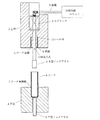
図6は、上記のチューブ・ハイドロフォーミング法を用いた従来の液圧拡管成形機の一例である。図に示すように、ワーク21の膨らます部分以外の部分をガイド22、23と芯金24によりシールした後、油圧ポンプ26を駆動し、ガイド22と芯金24の中央に形成された油路25に高圧の油を注入すると、芯金24の中央の油注入穴27から高圧の油がワーク21と芯金24との間に注入される。これにより、図6(b)に示すように、ワーク21と芯金24との間に油28が溜まり、油の圧力によってワーク21が外に向かって膨らみ、拡管成形が行われる。 FIG. 6 is an example of a conventional hydraulic tube forming machine using the above-described tube hydroforming method. As shown in the figure, after the work 21 is sealed with the guides 22, 23 and the cored bar 24, the hydraulic pump 26 is driven and the oil passage 25 formed at the center of the guide 22 and the cored bar 24. When high-pressure oil is injected into the core metal 24, high-pressure oil is injected between the workpiece 21 and the core metal 24 through the central oil injection hole 27 of the core metal 24. Thereby, as shown in FIG.6 (b), the oil 28 accumulates between the workpiece | work 21 and the metal core 24, the workpiece | work 21 swells outside with the pressure of oil, and pipe expansion molding is performed.
一方、被加工物に対して絞り加工、トリミング加工、孔明け加工等の複数の加工工程を順次実行する装置としてトランスファプレスが良く知られている。このようなトランスファプレスは、各プレス位置で成形されるワークを、金型の昇降動作に同期させて次のプレス位置へ順次搬送させながらプレス作業を行うようになっている(例えば、特許文献1参照)。 On the other hand, a transfer press is well known as an apparatus for sequentially executing a plurality of processing steps such as drawing, trimming, and drilling on a workpiece. Such a transfer press is configured to perform a pressing operation while sequentially transferring a workpiece formed at each pressing position to the next pressing position in synchronization with the lifting and lowering operation of the mold (for example, Patent Document 1). reference).
上記のように、従来の液圧拡管成形機は、ワークの膨らます部分以外の部分をガイドと芯金によりシールした後、油圧ポンプから高圧の油を注入する必要があり、拡管成形を行う場合には、専用機にワークをセットしなければならず、上記のようなトランスファプレスに組み込むことができかったので、ワークの加工速度が遅くなるという問題があった、
また、従来の液圧拡管成形機は高圧力を発生させるために、油圧ポンプを必要とするので、装置が高価になるという問題もあった。
As mentioned above, the conventional hydraulic pipe expansion molding machine needs to inject high-pressure oil from a hydraulic pump after sealing the parts other than the part where the workpiece swells with the guide and the metal core. Had to set the work on a dedicated machine and could not be incorporated into the transfer press as described above, so there was a problem that the processing speed of the work was slow,
In addition, the conventional hydraulic expansion pipe forming machine requires a hydraulic pump to generate a high pressure, which causes a problem that the apparatus becomes expensive.
本発明は、上記の問題に鑑みてなされたもので、液圧発生装置を必要とせず、汎用プレス機の順送金型やトランスファ金型に組み込むことができる液圧拡管成形用プレス金型を提供することを目的とする。 The present invention has been made in view of the above problems, and provides a press mold for forming a hydraulic pipe that can be incorporated into a progressive die or a transfer die of a general-purpose press without requiring a hydraulic pressure generator. The purpose is to do.
請求項1に係る発明は、内部に所定の位置の側面で開口する液路が形成され、スプリングにより下方に付勢する上金型ノックアウトおよび前記上金型ノックアウトを囲むように形成された筒状ワークの先端部分を侵入させる筒状ワークの通路とを有する上金型と、前記筒状ワークの後端部分を保持する下金型とからなる液圧拡管成形用金型をトランスファまたは順送プレスの金型に付設し、前記トランスファまたは順送プレスの上金型の下降に伴う前記液圧拡管成形用の上金型の下降時に前記液圧拡管成形用の下金型に保持されている筒状ワーク内に、前記液圧拡管成形用の上金型の液路の開口から液体を供給し、前記液圧拡管成形用の上金型の下降にしたがい前記液路の開口を閉塞して液体の供給を停止するとともに、供給された液体を前記液圧拡管成形用の上金型と下金型で圧縮することにより、前記筒状ワーク内に充填した液体の圧力で筒状ワークの中間部分を拡管することを特徴とする。 The invention according to claim 1, a liquid path which is open at the side of the predetermined position is formed inside the formed tubular so as to surround the mold knockout and the upper mold knockout over to biased downwardly by a spring Transfer or progressive press for a hydraulic expansion molding die comprising an upper die having a cylindrical workpiece passage for allowing the leading end portion of the workpiece to enter and a lower die holding the rear end portion of the cylindrical workpiece. cylinder that of annexed to the mold, it is held in the lower die of the liquid圧拡pipe molding during lowering of the upper mold of the liquid圧拡pipe molding due to lowering of the upper mold of the transfer or progressive press in Jo workpiece, the liquid圧拡pipe fluid is supplied from the upper mold of the liquid passage openings for forming the liquid closes the opening of the fluid passage in accordance with the lowering of the upper die of the liquid圧拡pipe molding It stops the supply of, before the supplied liquid By compressing at the upper die and the lower die for the liquid圧拡pipe forming, characterized by tube expansion of the intermediate portion of the cylindrical workpiece at a pressure of the liquid filled in the cylindrical workpiece within.
請求項1に係る発明の液圧拡管成形用プレス金型によれば、液体を媒介としてプレス機の上金型の上下運動によって高圧力を発生することができるので、油圧発生装置等を必要とすることなく、拡管成形を行うことができる。また、請求項1に係る発明の液圧拡管成形用プレス金型によれば、拡管成形機としての専用機を必要としないので、他のプレス成形との一貫生産が可能となり、同一工程の中で完結できるので、拡管成形を必要とするワーク加工のスピードアップを図ることができる。 According to the press mold for forming a hydraulic pipe according to the first aspect of the invention, a high pressure can be generated by the vertical movement of the upper mold of the press machine through the liquid, so that a hydraulic pressure generator or the like is required. It is possible to perform tube expansion molding without doing. Further, according to the liquid圧拡pipe molding press die of the invention according to claim 1, it does not require a dedicated machine as bulge forming machine enables integrated production with other press forming, the same process Because it can be completed inside, it is possible to speed up the work processing that requires tube expansion forming .
なお、下金型(以下、単に下型という。)に下型ノックアウトを設ければ、拡管成形後ワークを容易に下型から離すことができ、また、上金型(以下、単に上型という。)に設けられたワークが侵入する通路の上部にシール材を設ければ、液の加圧時の液体の漏れを防止することができ、拡管成形のための高い圧力を得ることができる。また、トランスファまたは順送プレスの金型に付設した液圧拡管成形用金型をによる液圧拡管成形加工部を以下液圧拡管成形機と呼ぶ。 The lower die (hereinafter, simply referred to. Lower die) by providing the lower knockout in the tube expansion after work easily can be separated from the lower mold, also, the upper die (hereinafter, simply upper die that If a sealing material is provided in the upper part of the passage into which the workpiece provided in .) Enters, it is possible to prevent leakage of the liquid when the liquid is pressurized, and to obtain a high pressure for tube expansion molding. In addition, a hydraulic pressure expansion forming portion using a hydraulic pressure expansion molding die attached to a transfer or progressive press die is hereinafter referred to as a hydraulic pressure expansion molding machine.
以下、本発明の液圧拡管成形機の実施例について説明する。
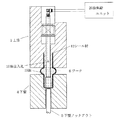
図1は、本発明の液圧拡管成形機がプレス上死点にある状態を示す図であり、この液圧拡管成形機は、上型1、上型ノックアウト2、スプリング3、下型4、下型ノックアウト5により構成されている。
上型ノックアウト2は上型1に形成された孔内を移動可能に設けられており、スプリング3は上型ノックアウト2を下方に付勢している。下型4にはワーク6を保持するワーク保持部7が形成されており、下型ノックアウト5は、ワーク6の拡管成形後に上昇することによってワーク6を下型4から押し出す。
Examples of the hydraulic expansion pipe forming machine of the present invention will be described below.
FIG. 1 is a view showing a state in which the hydraulic expansion pipe forming machine of the present invention is at the top dead center of the press. The hydraulic expansion pipe forming machine includes an upper mold 1, an upper mold knockout 2, a spring 3, a lower mold 4, It is constituted by a lower mold knockout 5.
The upper mold knockout 2 is provided so as to be movable in a hole formed in the upper mold 1, and the spring 3 biases the upper mold knockout 2 downward. The lower mold 4 is formed with a workpiece holding portion 7 that holds the workpiece 6, and the lower mold knockout 5 pushes out the workpiece 6 from the lower mold 4 by being lifted after tube expansion molding of the workpiece 6.
一方、上型ノックアウト2内には油路8が形成されており、この油路8に連通した油路9が油供給ユニット20に連結されている。油供給ユニット20から供給された油は油路9を介して上型ノックアウト2内の油路8に供給され、油注入孔10からワーク6内に流出する。また、上型1の下方にワーク6の先端部分が侵入するワーク通路11が形成されており、このワーク通路11の上端にシール材12が挿入されている。
On the other hand, an
次に、図1の液圧拡管成形機によるパーティカルチューブハイドロフォーミングの作用について、図2、図3の状態図及び図4のプレスと油供給及び拡管形成のタイミング図を用いて説明する。
前工程で加工されたワーク6がフィンガー(図示せず)により挟み持たれて下型4の上部に搬送され、下型4のワーク保持部7に保持された後、上型1が下降を開始する。そして、図4に示すように、上型ノックアウト2の油注入孔10がワーク6の上端を通過したタイミングで油供給ユニット20が油の供給を開始する。これにより、図2に示すように、上型ノックアウト2の油注入孔10からワーク6内に油13が供給される。
Next, the operation of the particulate tube hydroforming by the hydraulic tube forming machine of FIG. 1 will be described with reference to the state diagrams of FIGS. 2 and 3 and the timing diagram of the press and oil supply and tube forming of FIG.
After the workpiece 6 processed in the previous process is held between fingers (not shown) and conveyed to the upper portion of the lower die 4 and held by the workpiece holding portion 7 of the lower die 4, the upper die 1 starts to descend. To do. Then, as shown in FIG. 4, the oil supply unit 20 starts supplying oil at the timing when the oil injection hole 10 of the upper knockout 2 passes the upper end of the workpiece 6. Thereby, as shown in FIG. 2, the
そして、上型1がさらに下降し、上型ノックアウト2がワーク6の底部に到達した状態になると、スプリング3が圧縮されることにより、上型1のみが下降する。そして、上型ノックアウト2の油注入孔10が上型1内に入ったタイミングで油供給ユニット20が油の供給を停止するとともに、上型ノックアウト2が上型1に沈み込むことにより油注入孔10が塞がり、シールされる。 Then, when the upper die 1 is further lowered and the upper die knockout 2 reaches the bottom of the workpiece 6, the spring 3 is compressed, so that only the upper die 1 is lowered. The oil supply unit 20 stops supplying oil at the timing when the oil injection hole 10 of the upper mold knockout 2 enters the upper mold 1, and the oil injection hole is caused by the upper mold knockout 2 sinking into the upper mold 1. 10 is closed and sealed.
この後、さらに上型1が下降すると、上型1の下降によりワーク6内に閉じ込められた油13が圧縮され、外に向かってワーク6を膨らませるので、ワーク6の拡管成形が行われる。このとき、上型1に設けられたワークが侵入する通路11の上部にシール材12が設けられているので、油の漏れを防止することができ、拡管成形のための高い圧力を得ることができる。
Thereafter, when the upper die 1 is further lowered, the
そして、図3に示すように上型1がプレス下死点の位置まで到達すると、拡管成形が終了し、上型1が上昇を開始する。
上型1の上昇後、下型ノックアウト5が上昇するので、この下型ノックアウト5の上昇によりワーク6が上昇し、このワーク6の上昇とともに、フィンガーが金型に近づく方向に移動してワーク6がフィンガーにより挟み込まれ、次工程に搬送される。
Then, as shown in FIG. 3, when the upper die 1 reaches the position of the press bottom dead center, the tube expansion molding is finished, and the upper die 1 starts to rise.
Since the lower mold knockout 5 is raised after the upper mold 1 is lifted, the work 6 is lifted by the lift of the lower mold knockout 5, and as the work 6 is lifted, the fingers move in a direction approaching the mold and the work 6 Is sandwiched between fingers and conveyed to the next process.
次に、本発明の液圧拡管成形機を組み込んだトランスファプレスによる加工工程の一例について、以下、説明する。
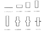
図5は、本発明の液圧拡管成形機を組み込んだトランスファプレスの各加工工程でのワークの形状を示す図であり、鋼板を円盤状に打ち抜くブランキング工程(1)、1次絞り工程(2)、2次絞り工程(3)、3次絞り工程(4)、4次絞り工程(5)により、ワークが円筒形状に成形された後、図1の液圧拡管成形機による拡管成形工程(6)によりワークが拡管成形される。
次に、油吸引工程(7)でワーク内の油が吸引された後、ツブシ工程(8)でワークの拡管部がつぶされることにより、張り出し量の大きい局所的な拡管部を有する円筒容器を製造することができる。
Next, an example of a processing process using a transfer press incorporating the hydraulic pressure expansion molding machine of the present invention will be described below.
FIG. 5 is a diagram showing the shape of a work in each processing step of a transfer press incorporating the hydraulic expansion pipe forming machine of the present invention, blanking step (1) for punching a steel plate into a disk shape (1), primary drawing step ( 2) After the workpiece has been formed into a cylindrical shape by the secondary drawing step (3), the third drawing step (4), and the fourth drawing step (5), the tube expansion forming step by the hydraulic tube forming machine of FIG. The workpiece is expanded by (6).
Next, after the oil in the workpiece is sucked in the oil suction step (7), the expanded tube portion of the workpiece is crushed in the bushing step (8), so that a cylindrical container having a local expanded portion with a large overhang amount is obtained. Can be manufactured.
以上のように、油を媒介として上型の上下運動によって高圧力を発生することができるので、油圧発生装置等を必要とすることなく、拡管成形を行うことができる。また、この液圧拡管成形機は汎用プレス機の順送金型やトランスファ金型に組み込むことができ、専用機を必要としないので、プレス成形との一貫生産が可能となり、ワーク加工のスピードアップを図ることができる。 As described above, since high pressure can be generated by the vertical movement of the upper mold through oil, tube expansion can be performed without the need for a hydraulic pressure generator or the like. In addition, this hydraulic expansion machine can be incorporated into a progressive die or transfer die of a general-purpose press machine, and does not require a dedicated machine, enabling integrated production with press molding and speeding up workpiece processing. Can be planned.
なお、上記の実施例ではワークを加圧するため、油を使用したが水などの他の液体を使用することもできる。また、図5に示したトランスファプレスによる加工工程は一例であり、様々なトランスファプレス及び順送プレスに本発明の液圧拡管成形機を組み込むことが可能である。 In the above embodiment, oil is used to pressurize the workpiece, but other liquids such as water may be used. Moreover, the processing process by the transfer press shown in FIG. 5 is an example, and it is possible to incorporate the liquid pressure expansion molding machine of the present invention into various transfer presses and progressive presses.
1 上型
2 上型ノックアウト
3 スプリング
4 下型
5 下型ノックアウト
6 ワーク
7 ワーク保持部
8、9 油路
10 油注入孔
11 ワーク通路
12 シール材
13 油
20 油供給ユニット
DESCRIPTION OF SYMBOLS 1 Upper mold 2 Upper mold knockout 3 Spring 4 Lower mold 5 Lower mold knockout 6 Work 7
Claims (1)
Priority Applications (1)
| Application Number | Priority Date | Filing Date | Title |
|---|---|---|---|
| JP2009236774A JP5517552B2 (en) | 2009-10-14 | 2009-10-14 | Press mold for hydraulic tube expansion molding |
Applications Claiming Priority (1)
| Application Number | Priority Date | Filing Date | Title |
|---|---|---|---|
| JP2009236774A JP5517552B2 (en) | 2009-10-14 | 2009-10-14 | Press mold for hydraulic tube expansion molding |
Publications (2)
| Publication Number | Publication Date |
|---|---|
| JP2011083785A JP2011083785A (en) | 2011-04-28 |
| JP5517552B2 true JP5517552B2 (en) | 2014-06-11 |
Family
ID=44077134
Family Applications (1)
| Application Number | Title | Priority Date | Filing Date |
|---|---|---|---|
| JP2009236774A Active JP5517552B2 (en) | 2009-10-14 | 2009-10-14 | Press mold for hydraulic tube expansion molding |
Country Status (1)
| Country | Link |
|---|---|
| JP (1) | JP5517552B2 (en) |
Families Citing this family (2)
| Publication number | Priority date | Publication date | Assignee | Title |
|---|---|---|---|---|
| CN103386431A (en) * | 2013-08-08 | 2013-11-13 | 贵州航天精工制造有限公司 | Soft flange molding method by rigid soft convex die compound bulging processing |
| JP7650302B2 (en) * | 2021-02-09 | 2025-03-24 | 住友重機械工業株式会社 | Molding device and metal pipe |
Family Cites Families (5)
| Publication number | Priority date | Publication date | Assignee | Title |
|---|---|---|---|---|
| JPS5680329A (en) * | 1979-12-04 | 1981-07-01 | Kaoru Abe | Hydraulic forging device |
| US4414834A (en) * | 1981-02-05 | 1983-11-15 | Carrier Corporation | Method for expanding tubular blanks |
| NL8600617A (en) * | 1986-03-10 | 1987-10-01 | Ultra Centrifuge Nederland Nv | METHOD FOR FORMING A CRICK IN A BUSH |
| JPH10314874A (en) * | 1997-05-22 | 1998-12-02 | Nisshin Kogyo Kk | Transfer press mold |
| JP2002282965A (en) * | 2001-03-26 | 2002-10-02 | Press Kogyo Co Ltd | Cylindrical product with flange and its forming method and apparatus |
-
2009
- 2009-10-14 JP JP2009236774A patent/JP5517552B2/en active Active
Also Published As
| Publication number | Publication date |
|---|---|
| JP2011083785A (en) | 2011-04-28 |
Similar Documents
| Publication | Publication Date | Title |
|---|---|---|
| US20080098789A1 (en) | Draw Forming Method and Device | |
| CN104741432B (en) | A kind of internal high pressure forming equipment and the technique of shaping | |
| CN104096742B (en) | Keep the hydro piercing method and device of workpiece wall flatness | |
| CN104923779A (en) | One-die-multiple-output ring-type magnet blank isobaric floating pressing die and method | |
| CN204842971U (en) | Isobaric compacting tool set that floats of many loop type magnet blanks of a mould | |
| JP5168743B2 (en) | Simultaneous mold making method and blank frame mold making apparatus | |
| CN104226776A (en) | Impact hydraulic expansion system for metal thin-walled pipes | |
| CN101244439A (en) | Design method of a mechanical-hydraulic auxiliary reverse drawing die | |
| JP5517552B2 (en) | Press mold for hydraulic tube expansion molding | |
| JP2015091591A (en) | Gear manufacturing method and forging device for the method | |
| JP5240467B2 (en) | Press forming method | |
| CN211707847U (en) | Lower-pressure hydraulic press for internal high-pressure bulging process | |
| KR101402334B1 (en) | Automatic pile pressing system and pile pressing method using that | |
| CN103464591B (en) | A kind of steel pipe throat mould | |
| CN110270619A (en) | A kind of circular material blank ultrahigh-pressure hydraulic breathing intensifying device | |
| JP5668698B2 (en) | Tube forming apparatus and method | |
| CN219786314U (en) | Pipe reaming forming device | |
| JP4274439B2 (en) | Molding equipment for closed forging | |
| CN214290344U (en) | Small machining device for winding pad positioning ring | |
| KR101647217B1 (en) | Hydro forming apparatus and method | |
| KR101024287B1 (en) | Forged Yellow Mold for Herbs | |
| CN112976424A (en) | Matched die hammering device of matched die machine | |
| JP2007000887A (en) | Forging method and double-action die apparatus for forging | |
| JPH07155998A (en) | Hydraulic die cushion device of punching hydraulic press of stepped forging | |
| CN112502137A (en) | Construction method of pile and special equipment |
Legal Events
| Date | Code | Title | Description |
|---|---|---|---|
| A621 | Written request for application examination |
Free format text: JAPANESE INTERMEDIATE CODE: A621 Effective date: 20120914 |
|
| A977 | Report on retrieval |
Free format text: JAPANESE INTERMEDIATE CODE: A971007 Effective date: 20131011 |
|
| A131 | Notification of reasons for refusal |
Free format text: JAPANESE INTERMEDIATE CODE: A131 Effective date: 20131031 |
|
| A521 | Written amendment |
Free format text: JAPANESE INTERMEDIATE CODE: A523 Effective date: 20131225 |
|
| TRDD | Decision of grant or rejection written | ||
| A01 | Written decision to grant a patent or to grant a registration (utility model) |
Free format text: JAPANESE INTERMEDIATE CODE: A01 Effective date: 20140401 |
|
| A61 | First payment of annual fees (during grant procedure) |
Free format text: JAPANESE INTERMEDIATE CODE: A61 Effective date: 20140401 |
|
| R150 | Certificate of patent or registration of utility model |
Ref document number: 5517552 Country of ref document: JP Free format text: JAPANESE INTERMEDIATE CODE: R150 |
|
| R250 | Receipt of annual fees |
Free format text: JAPANESE INTERMEDIATE CODE: R250 |
|
| R250 | Receipt of annual fees |
Free format text: JAPANESE INTERMEDIATE CODE: R250 |
|
| R250 | Receipt of annual fees |
Free format text: JAPANESE INTERMEDIATE CODE: R250 |
|
| R250 | Receipt of annual fees |
Free format text: JAPANESE INTERMEDIATE CODE: R250 |