JP5500575B2 - Mixing element, mixing device, mixing method, stirring blade, stirring device, and stirring method - Google Patents
Mixing element, mixing device, mixing method, stirring blade, stirring device, and stirring method Download PDFInfo
- Publication number
- JP5500575B2 JP5500575B2 JP2009132802A JP2009132802A JP5500575B2 JP 5500575 B2 JP5500575 B2 JP 5500575B2 JP 2009132802 A JP2009132802 A JP 2009132802A JP 2009132802 A JP2009132802 A JP 2009132802A JP 5500575 B2 JP5500575 B2 JP 5500575B2
- Authority
- JP
- Japan
- Prior art keywords
- laminated
- mixing
- hole
- fluid
- plate
- Prior art date
- Legal status (The legal status is an assumption and is not a legal conclusion. Google has not performed a legal analysis and makes no representation as to the accuracy of the status listed.)
- Active
Links
Images


Description
本発明は、混合要素、混合装置、混合方法、攪拌翼、攪拌装置及び攪拌方法に関するものであって、流体の混合、細分化、乳化等の処理をするための分野に利用される技術に係るものであり、動的混合にも静的混合にも使用される。 The present invention relates to a mixing element, a mixing device, a mixing method, a stirring blade, a stirring device, and a stirring method, and relates to a technique used in the field for processing fluid mixing, fragmentation, emulsification, and the like. Used for both dynamic and static mixing.
流体を混合する装置として、動的な混合装置としては攪拌槽内の流体中に攪拌羽根を配設して当該攪拌羽根を回転させて混合するものが広く使用されている。一方、静的な混合装置としては、スタティックミキサー等が広く使用されている。このような静的な混合装置は、一般的に可動部品を有していないため、化学工業や食品工業のように流体をライン中で混合する必要がある分野で広く使用されている。 As a device for mixing fluid, a dynamic mixing device widely used is a device in which a stirring blade is disposed in a fluid in a stirring tank and the stirring blade is rotated to perform mixing. On the other hand, static mixers are widely used as static mixing devices. Such static mixing devices generally have no moving parts and are therefore widely used in fields where fluids need to be mixed in a line, such as in the chemical and food industries.
特許文献1は、静止型の流体混合装置の例である。この流体混合装置は、中心に流通孔を穿設すると共に、一面に前面開放の多角形状の小室をハニカム状に多数配列して形成した大小2枚の円板を同心的に重合してなる複数の導流単位体からなる。大径円板の小室と小径円板の小室は互いの小室が対向する他の複数の小室に連通するように位置を違えて配列させ、これら複数の導流単位体を重ね合わせたものである。
当該流体混合装置においては、流体は、導流単位体の各小室を移動する際に分散、反転、合流することにより混合されるとともに、さらに各小室における渦流、乱流、衝突等によって混合される。そして、導流単位体の中央部から外側へ又は外側から中央部へと放射状に再分散と集合を交互に繰り返して混合させるもので、高い混合効果が得られることを特徴としている。
In the fluid mixing device, the fluid is mixed by being dispersed, inverted, and joined when moving through each chamber of the flow guiding unit, and further mixed by vortex, turbulence, collision, etc. in each chamber. . And it is what mixes by repeating re-dispersion and a gathering alternately radially from the center part to the outside or from the outside to the center part, and is characterized by obtaining a high mixing effect.
しかし、前記流体混合装置は、流体の流れる流路面積が、前記大小2枚の円板の小室が連通する部分のみであり、混合効果に限界がある。また、流体の流量が多いと装置全体の圧力損失が大きくなって大きな動力が必要とされるという問題点があった。
また、小室のデッドスペースに流体の残留物や異物が付着して、洗浄作業に手間を要するというメンテナンス上の問題点があった。
However, the fluid mixing device has a limited mixing effect because the flow path area through which the fluid flows is only the portion where the small chambers of the two large and small disks communicate. Further, when the flow rate of the fluid is large, there is a problem that the pressure loss of the entire apparatus becomes large and a large power is required.
In addition, there is a problem in maintenance that a fluid residue or a foreign substance adheres to the dead space of the small chamber and requires a lot of time for cleaning work.
一方、攪拌槽内の液体を混合するためには、タービン翼等が広く使用されるが、混合効率を高くするために特許文献2の攪拌翼がある。これは、攪拌軸に装着せしめられる支持体の両面に、その片面につき回転平面に対して並列せしめられた2個の部分攪拌器を1組として、その4組が装着され、且つ各組の部分攪拌器の外側開口は回転方向に対して後方になるに伴って逐次内側に後退せしめられているものであり、短時間でありながら大きい混合度が容易に、確実に、しかもわずかな動力で得られる。
On the other hand, in order to mix the liquid in the stirring tank, turbine blades and the like are widely used, but there is a stirring blade of
しかし、上記攪拌翼であっても流体が混合されるのは支持体に取り付けられた部分攪拌器周辺に限られているため、混合効率には限界がある。 However, even with the above-described stirring blade, the mixing efficiency is limited because the fluid is mixed only around the partial stirrer attached to the support.
さらに、特許文献3は、特許文献1の導流単位体を混合回転体として攪拌槽内の液中に配設したものであるが、やはり流体が混合されるのは混合回転体周辺に限られているため、混合効率には限界がある。
Further, in
本発明は、前記に鑑みてなされたものであり、混合要素、混合装置、混合方法として、小さなスペースで高い混合効果を有し、多くの流量の流体を混合することが可能なこと、洗浄作業を容易に行えることを課題とする。
また、攪拌翼、攪拌装置及び攪拌方法として、小さなスペースで高い混合効果を有し、洗浄作業を容易に行えることを課題とする。
The present invention has been made in view of the above, and has a high mixing effect in a small space as a mixing element, a mixing device, and a mixing method, and can mix a large amount of fluids, and a cleaning operation. It is an object to be able to easily perform.
Another object of the present invention is to provide a stirring blade, a stirring device, and a stirring method that have a high mixing effect in a small space and can easily perform a cleaning operation.
本発明は、前記課題を解決するため、以下の混合要素、混合装置、混合方法、攪拌翼、攪拌装置及び攪拌方法を提供する。
(1)混合要素
本発明に係る混合要素の一つの構成は、
複数の積層エレメントが積層される積層体と、当該積層体を挟んで対向配置される第1の板と第2の板とを備え、
前記積層エレメントは、複数の第1の貫通孔を有し、
前記第2の板は、前記積層エレメントの少なくとも1つの第1の貫通孔に連通する貫通孔を有し、
前記積層エレメントは、前記第1の貫通孔の一部又は全部が、隣接する積層エレメントの第1の貫通孔とその位置をずらせて部分的に重なり合うように配置され、且つ隣接する積層エレメントの第1の貫通孔との間で流体を積層エレメントの延在する方向に流通可能に連通するように配置されていることを特徴とする(第1の技術的手段)。
The present invention provides the following mixing element, mixing device, mixing method, stirring blade, stirring device, and stirring method in order to solve the above problems.
(1) Mixing element One configuration of the mixing element according to the present invention is:
A laminated body in which a plurality of laminated elements are laminated, and a first plate and a second plate arranged to face each other with the laminated body interposed therebetween,
The laminated element has a plurality of first through holes,
The second plate has a through hole communicating with at least one first through hole of the laminated element,
The laminated element is arranged so that a part or all of the first through holes partially overlap with the first through holes of the adjacent laminated elements, and the first through holes of the adjacent laminated elements It is arrange | positioned so that a fluid may be connected to the through-hole of 1 through so that a flow is possible in the direction where a lamination | stacking element is extended (1st technical means).
本構成によれば、第2の板の貫通孔から流入した流体は、第2の板の貫通孔に連通する積層エレメントの第1の貫通孔から積層体内部に流入し、積層体内部の連通する第1の貫通孔を流通しながら混合され、積層体から流出する。
積層体の積層方向両端部では、第1の板と第2の板により、積層エレメントの第1の貫通孔は積層方向に閉じている。従って、積層体内部に流入した流体は、積層エレメントの延在する方向に連通する第1の貫通孔を流通するように案内される。
上記とは逆に、積層エレメントの第1の貫通孔から積層体内部に流入した流体が第2の板の貫通孔から流出する場合でも、流体は、積層体内部の連通する第1の貫通孔を流通しながら混合される。
なお、ここで、積層エレメントの延在する方向とは、積層エレメントの積層方向に対して垂直方向をいう。
According to this configuration, the fluid that has flowed from the through hole of the second plate flows into the laminated body from the first through hole of the laminated element that communicates with the through hole of the second plate, and communicates inside the laminated body. Are mixed while flowing through the first through hole to flow out of the laminate.
At both ends in the stacking direction of the stacked body, the first through hole of the stacking element is closed in the stacking direction by the first plate and the second plate. Therefore, the fluid that has flowed into the laminated body is guided so as to flow through the first through hole that communicates in the extending direction of the laminated element.
Contrary to the above, even when the fluid flowing into the laminated body from the first through-hole of the laminated element flows out of the through-hole of the second plate, the fluid is communicated with the first through-hole inside the laminated body. Mixed while circulating.
Here, the extending direction of the laminated element means a direction perpendicular to the laminated direction of the laminated element.
さらに、本構成によれば、流体は、当該第1の貫通孔から積層方向に連通する他の第1の貫通孔に流出し、また、その逆に積層方向に連通する他の第1の貫通孔から当該第1の貫通孔に流入することにより複雑に連通する第1の貫通孔で流入及び流出を繰り返すので、より流体が複雑に流動し混合効果が増大する。また、積層エレメントの積層枚数を多くすることにより、流体の流れる積層エレメントが延在する方向への断面積が大きくなるので、より多くの流量の流体を混合することができる。 Furthermore, according to this configuration, the fluid flows out from the first through hole to the other first through hole communicating with the stacking direction, and conversely, the other first through hole communicating with the stacking direction. Since the inflow and outflow are repeated in the first through-hole communicating in a complicated manner by flowing into the first through-hole from the hole, the fluid flows more complicated and the mixing effect is increased. Moreover, since the cross-sectional area in the direction in which the laminated element through which the fluid flows increases by increasing the number of laminated laminated elements, a fluid having a larger flow rate can be mixed.
本発明に係る他の局面に従った混合要素の構成は、
第1の技術的手段に係る混合要素において、
前記複数の積層エレメント、前記第1の板及び前記第2の板は、分解可能に固定されていることを特徴とする(第2の技術的手段)。
The composition of the mixing element according to another aspect of the present invention is:
In the mixing element according to the first technical means,
The plurality of laminated elements, the first plate, and the second plate are fixed so as to be disassembled (second technical means).
本構成によれば、混合要素は、各積層エレメント、第1の板及び第2の板の各々に分解することにより、積層エレメントの第1の貫通孔に残留した残留物や異物の除去のような洗浄作業を容易にすることができる。 According to this configuration, the mixing element is decomposed into each of the laminated elements, the first plate, and the second plate, thereby removing residues and foreign matters remaining in the first through holes of the laminated element. Cleaning operation can be facilitated.
本発明に係る他の局面に従った混合要素の構成は、
第1又は第2の技術的手段に係る混合要素において、
前記複数の積層エレメント、前記第1の板及び前記第2の板は、分割可能であることを特徴とする(第3の技術的手段)。
The composition of the mixing element according to another aspect of the present invention is:
In the mixing element according to the first or second technical means,
The plurality of laminated elements, the first plate, and the second plate can be divided (third technical means).
本構成によれば、混合要素は、各積層エレメント、第1の板及び第2の板の各々が分割可能なので、複雑な形状のものにも容易に配設することができる。 According to this configuration, the mixing elements can be easily arranged even in complicated shapes because each of the laminated elements, the first plate, and the second plate can be divided.
本発明に係る他の局面に従った混合要素の構成は、
第1乃至第3の技術的手段に係る混合要素において、
前記積層エレメントは、複数の貫通孔を有する金属板を穿設して形成されていることを特徴とする(第4の技術的手段)。
The composition of the mixing element according to another aspect of the present invention is:
In the mixing element according to the first to third technical means,
The laminated element is formed by drilling a metal plate having a plurality of through holes (fourth technical means).
本構成によれば、複数の第1の貫通孔を有する市販のパンチングメタル等の金属板を打ち抜き加工等により穿設して短時間で大量に積層エレメントを製作することができる。従って、安価に混合要素を製作することができる。 According to this configuration, it is possible to produce a large number of laminated elements in a short time by punching a metal plate such as a commercially available punching metal having a plurality of first through holes by punching or the like. Therefore, the mixing element can be manufactured at a low cost.
本発明に係る他の局面に従った混合要素の構成は、
第1乃至第4のいずれかの技術的手段に係る混合要素において、
前記第1の板の外側形状が、前記第2の板の貫通孔より大きいことを特徴とする(第5の技術的手段)。
The composition of the mixing element according to another aspect of the present invention is:
In the mixing element according to any one of the first to fourth technical means,
The outer shape of the first plate is larger than the through hole of the second plate (fifth technical means).
本構成によれば、流体が積層体を通過するに際し、積層方向に短絡して流れることを抑止することができる。そのため、積層体内部に流入した流体は、積層エレメントの延在する方向へ流通し易くなるので、より多くの連通する第1の貫通孔を流通する。従って、流体の混合効率を向上させることができる。 According to this structure, when a fluid passes a laminated body, it can suppress that it short-circuits in a lamination direction and flows. Therefore, the fluid that has flowed into the laminated body easily circulates in the direction in which the laminated elements extend, and therefore circulates through more communicating first through holes. Therefore, the fluid mixing efficiency can be improved.
本発明に係る他の局面に従った混合要素の構成は、
複数の積層エレメントが積層される積層体と、当該積層体を挟んで対向配置される第1の板と第2の板とを備え、
前記積層エレメントは、複数の第1の貫通孔を有し、
前記第2の板は、前記積層エレメントの少なくとも1つの第1の貫通孔に連通する貫通孔を有し、
前記積層エレメントは、前記第1の貫通孔の一部又は全部が、隣接する積層エレメントの第1の貫通孔との間で流体を積層エレメントの延在する方向に流通可能に連通するように配置され、
前記積層エレメントは、第1の貫通孔より大きい第2の貫通孔を有し、且つ前記第2の貫通孔が積層方向に連通して前記積層体に中空部が形成されるように配置されており、
前記第2の板の貫通孔が前記中空部を介して前記積層エレメントの少なくとも1つの第1の貫通孔に連通されていることを特徴とする(第6の技術的手段)。
The composition of the mixing element according to another aspect of the present invention is:
A laminated body in which a plurality of laminated elements are laminated, and a first plate and a second plate arranged to face each other with the laminated body interposed therebetween,
The laminated element has a plurality of first through holes,
The second plate has a through hole communicating with at least one first through hole of the laminated element,
The laminated element is arranged such that a part or all of the first through-hole communicates with a first through-hole of an adjacent laminated element so that fluid can flow in the direction in which the laminated element extends. And
The laminated element has a second through hole larger than the first through hole, and is arranged such that the second through hole communicates in the laminating direction to form a hollow portion in the laminated body. And
A through hole of the second plate is communicated with at least one first through hole of the laminated element through the hollow portion (sixth technical means).
本構成によれば、第2の板の貫通孔から流入した流体は、混合要素の中空部に流入する。ここで、中空部とは、積層エレメントの第2の貫通孔が積層して形成される中空状の空間部をいう。中空部では流体が流れる際の流動抵抗が小さいので、積層方向の圧力分布が小さい。従って、流体は積層方向の位置に関らず、略均等に中空部内側面に開く第1の貫通孔を介して積層体内部に流入し、積層エレメントの延在する方向へ流れる。
上記とは逆に、積層エレメントの第1の貫通孔から積層体内部に流入した流体が中空部へ流出する場合でも、流体は積層方向の位置に関らず略均等に積層体内部を積層エレメントの延在する方向へ流れ、略均等に積層体内部から中空部内側面に開く第1の貫通孔から流出する。
According to this configuration, the fluid that has flowed from the through hole of the second plate flows into the hollow portion of the mixing element. Here, the hollow portion refers to a hollow space portion formed by laminating the second through holes of the laminated element. Since the flow resistance when the fluid flows in the hollow portion is small, the pressure distribution in the stacking direction is small. Therefore, regardless of the position in the stacking direction, the fluid flows into the stacked body through the first through holes that open to the inner surface of the hollow portion almost evenly and flows in the direction in which the stacking element extends.
Contrary to the above, even when the fluid that has flowed into the laminated body from the first through-hole of the laminated element flows out into the hollow portion, the fluid passes through the laminated body almost uniformly regardless of the position in the lamination direction. Flows out from the first through hole that opens from the inside of the laminated body to the inner side surface of the hollow portion.
(2)混合装置
本発明に係る混合装置の一つの構成は、
第1乃至第6のいずれかの技術的手段に係る混合要素と、当該混合要素を収容する入口及び出口を有するケーシングとを備え、
前記混合要素における第1の板は、前記ケーシング内側形状よりも小さい外側形状を有し、
前記混合要素における第2の板は、前記ケーシング内側形状と略同一の外側形状を有し、且つ当該第2の板の外側面が前記ケーシング内側面と略内接されていることを特徴とする(第7の技術的手段)。
(2) Mixing device One configuration of the mixing device according to the present invention is as follows.
A mixing element according to any one of the first to sixth technical means, and a casing having an inlet and an outlet for accommodating the mixing element,
The first plate of the mixing element has an outer shape smaller than the casing inner shape;
The second plate of the mixing element has an outer shape that is substantially the same as the inner shape of the casing, and the outer surface of the second plate is substantially inscribed with the inner surface of the casing. (Seventh technical means).
本構成によれば、ケーシングの入口から流入した流体は、第2の板の貫通孔を経由して第2の板の貫通孔に連通する積層エレメントの第1の貫通孔から積層体内部に流入する。そして、積層体内部の連通する第1の貫通孔を流通しながら混合され、積層体から流出し、さらに、ケーシング出口から流出する。
上記とは逆に、積層体内部の流体が第2の板の貫通孔から流出する場合には、流体は、積層エレメントの第1の貫通孔から積層体内部に流入する。そして、積層体内部の連通する第1の貫通孔を流通しながら混合され、第2の板の貫通孔と連通する第1の貫通孔から流出し、さらに、ケーシング出口から流出する。
According to this configuration, the fluid flowing in from the inlet of the casing flows into the laminated body from the first through hole of the laminated element communicating with the through hole of the second plate via the through hole of the second plate. To do. And it mixes, distribute | circulating the 1st through-hole which connects the inside of a laminated body, flows out from a laminated body, and also flows out from a casing exit.
Contrary to the above, when the fluid inside the laminated body flows out from the through hole of the second plate, the fluid flows into the laminated body from the first through hole of the laminated element. And it mixes, distribute | circulating the 1st through-hole which connects inside a laminated body, flows out from the 1st through-hole connected with the through-hole of a 2nd board, and also flows out from a casing exit.
積層体の積層方向両端部では、第1の板と第2の板により、積層エレメントの第1の貫通孔は積層方向に閉じている。従って、積層体内部に流入した流体は、積層エレメントの延在する方向に連通する第1の貫通孔を流通するように案内される。
なお、混合要素を構成する第1の板は、ケーシング内側形状よりも小さい外側形状を有しているので、流体が積層体内部に流入するのを妨げられることはない。また、第2の板の外側面はケーシング内側面と略内接しているので、流体を第2の板の貫通孔から積層体内部に確実に流入させることができる。
なお、ここで、積層エレメントの延在する方向とは、積層エレメントの積層方向に対して垂直方向をいう。
At both ends in the stacking direction of the stacked body, the first through hole of the stacking element is closed in the stacking direction by the first plate and the second plate. Therefore, the fluid that has flowed into the laminated body is guided so as to flow through the first through hole that communicates in the extending direction of the laminated element.
In addition, since the 1st board which comprises a mixing element has outer shape smaller than casing inner shape, it does not prevent that a fluid flows in into a laminated body. Further, since the outer surface of the second plate is substantially inscribed with the inner surface of the casing, the fluid can surely flow into the laminated body from the through hole of the second plate.
Here, the extending direction of the laminated element means a direction perpendicular to the laminated direction of the laminated element.
さらに、本構成によれば、流体は、当該第1の貫通孔から積層方向に連通する他の第1の貫通孔に流出し、また、その逆に積層方向に連通する他の第1の貫通孔から当該第1の貫通孔に流入することにより複雑に連通する第1の貫通孔で流入及び流出を繰り返すので、より流体が複雑に流動し混合効果が増大する。また、積層エレメントの積層枚数を多くすることにより、流体の流れる積層エレメントが延在する方向への断面積が大きくなるので、より多くの流量の流体を混合することができる。 Furthermore, according to this configuration, the fluid flows out from the first through hole to the other first through hole communicating with the stacking direction, and conversely, the other first through hole communicating with the stacking direction. Since the inflow and outflow are repeated in the first through-hole communicating in a complicated manner by flowing into the first through-hole from the hole, the fluid flows more complicated and the mixing effect is increased. Moreover, since the cross-sectional area in the direction in which the laminated element through which the fluid flows increases by increasing the number of laminated laminated elements, a fluid having a larger flow rate can be mixed.
さらに、本構成によれば、ケーシング内部で流体を混合することができるため、インライン静止型混合装置としての使用が可能である。従って、流体を連続的に混合することができる。 Furthermore, according to this structure, since a fluid can be mixed inside a casing, it can be used as an in-line static mixing device. Therefore, the fluid can be mixed continuously.
(3)混合方法
本発明に係る混合方法の一つの構成は、
前記第7の技術的手段に係る混合装置により流体を混合する方法であって、
前記混合要素内部に流入した流体を、前記積層エレメントの延在する方向に前記第1の貫通孔に流通させて前記混合要素外部に流出させることを特徴とする(第8の技術的手段)。
(3) Mixing method One configuration of the mixing method according to the present invention is:
A method of mixing fluid with a mixing device according to the seventh technical means,
The fluid that has flowed into the mixing element is caused to flow through the first through-hole in the direction in which the laminated element extends to flow out of the mixing element (eighth technical means).
本方法によれば、流体は、第2の板の貫通孔を経由して第2の板の貫通孔に連通する積層エレメントの少なくとも1つの第1の貫通孔から積層体内部に流入する。そして、積層体内部の連通する第1の貫通孔を流通しながら混合され、積層体から流出し、さらに、ケーシング出口から流出する。
上記とは逆に、積層体内部の流体が第2の板の貫通孔から流出する場合には、流体は、積層エレメントの第1の貫通孔から積層体内部に流入する。そして、積層体内部の連通する第1の貫通孔を流通しながら混合され、第2の板の貫通孔と連通する第1の貫通孔から流出し、さらに、ケーシング出口から流出する。
According to this method, the fluid flows into the laminated body from at least one first through hole of the laminated element that communicates with the through hole of the second plate via the through hole of the second plate. And it mixes, distribute | circulating the 1st through-hole which connects the inside of a laminated body, flows out from a laminated body, and also flows out from a casing exit.
Contrary to the above, when the fluid inside the laminated body flows out from the through hole of the second plate, the fluid flows into the laminated body from the first through hole of the laminated element. And it mixes, distribute | circulating the 1st through-hole which connects inside a laminated body, flows out from the 1st through-hole connected with the through-hole of a 2nd board, and also flows out from a casing exit.
積層体の積層方向両端部では、対向配置された第1の板と第2の板により積層エレメントの第1の貫通孔は積層方向に閉じている。従って、積層体内部に流入した流体は、積層エレメントの延在する方向に連通する第1の貫通孔を流通するように案内される。
なお、第1の板は、ケーシング内側形状よりも小さい外側形状を有しているので、流体が積層体内部に流入するのを妨げられることはない。また、第2の板の外側面はケーシング内側面と略内接しているので、流体を第2の板の貫通孔から積層体内部に確実に流入させることができる。
なお、ここで、積層エレメントの延在する方向とは、積層エレメントの積層方向に対して垂直方向をいう。
At both ends in the stacking direction of the stacked body, the first through-holes of the stacking element are closed in the stacking direction by the first plate and the second plate arranged to face each other. Therefore, the fluid that has flowed into the laminated body is guided so as to flow through the first through hole that communicates in the extending direction of the laminated element.
Since the first plate has an outer shape smaller than the inner shape of the casing, the fluid is not prevented from flowing into the laminated body. Further, since the outer surface of the second plate is substantially inscribed with the inner surface of the casing, the fluid can surely flow into the laminated body from the through hole of the second plate.
Here, the extending direction of the laminated element means a direction perpendicular to the laminated direction of the laminated element.
さらに、本方法によれば、流体は、当該第1の貫通孔から積層方向に連通する他の第1の貫通孔に流出し、また、その逆に積層方向に連通する他の第1の貫通孔から当該第1の貫通孔に流入することにより複雑に連通する第1の貫通孔で流入及び流出を繰り返すので、より流体が複雑に流動し混合効果が増大する。また、積層エレメントの積層枚数を多くすることにより、流体の流れる積層エレメントが延在する方向への断面積が大きくなるので、より多くの流量の流体を混合することができる。 Furthermore, according to this method, the fluid flows out from the first through hole to the other first through hole communicating in the stacking direction, and conversely, the other first through hole communicating in the stacking direction. Since the inflow and outflow are repeated in the first through-hole communicating in a complicated manner by flowing into the first through-hole from the hole, the fluid flows more complicated and the mixing effect is increased. Moreover, since the cross-sectional area in the direction in which the laminated element through which the fluid flows increases by increasing the number of laminated laminated elements, a fluid having a larger flow rate can be mixed.
さらに、本方法によれば、ケーシング内部で流体を混合することができるためインライン静止型混合装置としての応用が可能である。従って、流体を連続的に混合することができる。 Furthermore, according to the present method, the fluid can be mixed inside the casing, so that it can be applied as an in-line static mixing device. Therefore, the fluid can be mixed continuously.
(4)攪拌装置
本発明に係る攪拌装置の一つの構成は、
第6の技術的手段に係る混合要素が回転駆動される回転軸に取り付けられ、当該混合要素が攪拌槽内の流体中に配設されていることを特徴とする(第9の技術的手段)。
(4) Stirrer One configuration of the stirrer according to the present invention is as follows.
The mixing element according to the sixth technical means is attached to a rotating shaft that is rotationally driven, and the mixing element is disposed in the fluid in the stirring vessel (ninth technical means) .
本構成によれば、回転軸の回転により混合要素が回転し、混合要素内部の流体に遠心力が作用し、流体は連通する第1の貫通孔を流通しながら混合させられ、積層体の外側面に開く第1の貫通孔から吐出させられる。攪拌槽内部の流体は、混合要素の回転により中空部に吸い込まれ、中空部の内側面に開く第1の貫通孔を介して積層体内部に流入する。以上により、流体は混合される。
積層体の積層方向両端部では、第1の板及び第2の板により、積層エレメントの第1の貫通孔は積層方向に閉じている。従って、積層体内部に流入した流体は、積層エレメントの延在する方向へ連通する第1の貫通孔を流通するように案内される。
なお、上記中空部とは、積層エレメントの第2の貫通孔が積層して形成される中空状の空間部をいう。
According to this configuration, the mixing element is rotated by the rotation of the rotating shaft, the centrifugal force acts on the fluid inside the mixing element, and the fluid is mixed while flowing through the communicating first through hole. It discharges from the 1st through-hole opened to a side surface. The fluid inside the stirring tank is sucked into the hollow portion by the rotation of the mixing element, and flows into the laminated body through the first through hole that opens on the inner surface of the hollow portion. Thus, the fluid is mixed.
At both ends in the stacking direction of the stacked body, the first through hole of the stacking element is closed in the stacking direction by the first plate and the second plate. Therefore, the fluid that has flowed into the laminated body is guided so as to flow through the first through hole that communicates in the direction in which the laminated element extends.
In addition, the said hollow part means the hollow space part formed by laminating | stacking the 2nd through-hole of a lamination | stacking element.
さらに、本構成によれば、流体は、当該第1の貫通孔から積層方向に連通する他の第1の貫通孔に流出し、また、その逆に積層方向に連通する他の第1の貫通孔から当該第1の貫通孔に流入することにより複雑に連通する第1の貫通孔で流入及び流出を繰り返すので、より流体が複雑に流動し混合効果が増大する。また、積層エレメントの積層枚数を多くすることにより、流体の流れる積層エレメントが延在する方向への断面積が大きくなるので、攪拌槽内を循環する流体の流量が多くなって、より混合時間を短くすることができる。 Furthermore, according to this configuration, the fluid flows out from the first through hole to the other first through hole communicating with the stacking direction, and conversely, the other first through hole communicating with the stacking direction. Since the inflow and outflow are repeated in the first through-hole communicating in a complicated manner by flowing into the first through-hole from the hole, the fluid flows more complicated and the mixing effect is increased. Also, by increasing the number of laminated elements, the cross-sectional area in the direction in which the laminated element through which the fluid flows increases, so the flow rate of the fluid circulating in the agitation tank increases and the mixing time is further increased. Can be shortened.
中空部を形成する第2の貫通孔は積層エレメントの第1の貫通孔より大きく、流体が中空部を流れる際の流動抵抗は積層体内部を流れる際の流動抵抗より小さいので、圧力損失も小さい。そのため、流体は、積層エレメントの積層枚数が多い場合でも、積層方向の位置に関らず略均等に各積層エレメントの内周部に到達する。ゆえに、流体は、積層方向の位置に関らず、積層体内部を内周部から外周部へ略均等に流れる。
また、従来の攪拌翼を使用した攪拌装置では主に攪拌翼近傍の小さな空間でしか混合エネルギーを流体に与えられなかったが、本構成によれば撹拌槽に占める混合要素の体積割合を大きくすることにより、従来の攪拌翼と比較して格段に大きな空間で混合エネルギーを流体に与えられる。従って、攪拌槽内の空間を有効に利用することができ、効率的に流体を混合することができる。
The second through hole forming the hollow portion is larger than the first through hole of the laminated element, and the flow resistance when the fluid flows through the hollow portion is smaller than the flow resistance when flowing through the inside of the laminated body, so the pressure loss is also small. . Therefore, even when the number of laminated elements is large, the fluid reaches the inner peripheral portion of each laminated element substantially evenly regardless of the position in the lamination direction. Therefore, the fluid flows substantially uniformly from the inner peripheral portion to the outer peripheral portion within the stacked body regardless of the position in the stacking direction.
In addition, in the conventional stirring apparatus using the stirring blade, the mixing energy can be given to the fluid mainly in a small space near the stirring blade. However, according to this configuration, the volume ratio of the mixing element in the stirring tank is increased. As a result, the mixing energy can be given to the fluid in a much larger space compared to the conventional stirring blade. Therefore, the space in the stirring tank can be used effectively, and the fluid can be mixed efficiently.
本発明に係る他の局面に従った攪拌装置の構成は、
第9の技術的手段に係る攪拌装置において、
前記混合要素は、前記積層体に形成される中空部の内側に、前記積層エレメントの積層方向に伸びる内板が配設されていることを特徴とする(第10の技術的手段)。
The configuration of the stirring device according to another aspect of the present invention is as follows:
In the stirring device according to the ninth technical means,
The mixing element is characterized in that an inner plate extending in the stacking direction of the stacked elements is disposed inside a hollow portion formed in the stacked body (tenth technical means).
本構成によれば、混合要素は、中空部の内側に積層方向に伸びる内板を有するので、混合要素の回転により内板の回転方向と反対側の面近傍に流体の吸込み流が発生する。従って、より多くの流体が積層体内部に流入し、連通する第1の貫通孔を流通して混合されるので、さらに効率的に流体が混合される。 According to this configuration, since the mixing element has the inner plate extending in the stacking direction inside the hollow portion, a suction flow of fluid is generated in the vicinity of the surface opposite to the rotation direction of the inner plate by the rotation of the mixing element. Accordingly, a larger amount of fluid flows into the laminated body and flows through the first through-holes that are in communication to be mixed, so that the fluid is mixed more efficiently.
(5)攪拌方法
本発明に係る攪拌方法は、
第9又は第10の技術的手段に係る攪拌装置により流体を攪拌する方法であって、
前記混合要素が、自己の回転動作により、前記第2の板の貫通孔を介して前記積層エレメントの第2の貫通孔から混合要素内部に流入した流体を、前記積層エレメントの複数の第1の貫通孔を介して混合要素の外側部から流出させることを特徴とする(第11の技術的手段)。
(5) Stirring method The stirring method according to the present invention includes:
A method of stirring fluid by a stirring device according to the ninth or tenth technical means,
The mixing element causes the fluid that has flowed into the mixing element from the second through-hole of the stacked element through the through-hole of the second plate by the self-rotating operation, and the plurality of first elements of the stacked element It flows out from the outer side part of a mixing element through a through-hole (11th technical means).
本方法によれば、回転軸の回転により混合要素が回転し、混合要素内部の流体に遠心力が作用し、流体は連通する第1の貫通孔を流通しながら混合させられ、積層体の外側面に開く第1の貫通孔から吐出させられる。攪拌槽内部の流体は、混合要素の回転により中空部に吸い込まれ、中空部の内側面に開く第1の貫通孔を介して積層体内部に流入する。以上により、流体は混合される。
積層体の積層方向両端部では、第1の板及び第2の板により、積層エレメントの第1の貫通孔は積層方向に閉じている。従って、積層体内部に流入した流体は、積層エレメントの延在する方向へ連通する第1の貫通孔を流通するように案内される。
なお、上記中空部とは、積層エレメントの第2の貫通孔が積層して形成される中空状の空間部をいう。
According to this method, the mixing element is rotated by the rotation of the rotating shaft, the centrifugal force acts on the fluid inside the mixing element, and the fluid is mixed while flowing through the first through hole communicating with the mixing element. It discharges from the 1st through-hole opened to a side surface. The fluid inside the stirring tank is sucked into the hollow portion by the rotation of the mixing element, and flows into the laminated body through the first through hole that opens on the inner surface of the hollow portion. Thus, the fluid is mixed.
At both ends in the stacking direction of the stacked body, the first through hole of the stacking element is closed in the stacking direction by the first plate and the second plate. Therefore, the fluid that has flowed into the laminated body is guided so as to flow through the first through hole that communicates in the direction in which the laminated element extends.
In addition, the said hollow part means the hollow space part formed by laminating | stacking the 2nd through-hole of a lamination | stacking element.
さらに、本方法によれば、流体は、当該第1の貫通孔から積層方向に連通する他の第1の貫通孔に流出し、また、その逆に積層方向に連通する他の第1の貫通孔から当該第1の貫通孔に流入することにより複雑に連通する第1の貫通孔で流入及び流出を繰り返すので、より流体が複雑に流動し混合効果が増大する。また、積層エレメントの積層枚数を多くすることにより、流体の流れる積層エレメントが延在する方向への断面積が大きくなるので、攪拌槽内を循環する流体の流量が多くなって、より混合時間を短くすることができる。
また、従来の攪拌翼を使用した攪拌装置では主に攪拌翼近傍の小さな空間でしか混合エネルギーを流体に与えられなかったが、本方法によれば撹拌槽に占める混合要素の体積割合を大きくすることにより、従来の攪拌翼と比較して格段に大きな空間で混合エネルギーを流体に与えられる。従って、攪拌槽内の空間を有効に利用することができ、効率的に流体を混合することができる。
Furthermore, according to this method, the fluid flows out from the first through hole to the other first through hole communicating in the stacking direction, and conversely, the other first through hole communicating in the stacking direction. Since the inflow and outflow are repeated in the first through-hole communicating in a complicated manner by flowing into the first through-hole from the hole, the fluid flows more complicated and the mixing effect is increased. Also, by increasing the number of laminated elements, the cross-sectional area in the direction in which the laminated element through which the fluid flows increases, so the flow rate of the fluid circulating in the agitation tank increases and the mixing time is further increased. Can be shortened.
In addition, in the conventional stirring apparatus using the stirring blade, the mixing energy can be given to the fluid mainly in a small space near the stirring blade. However, according to this method, the volume ratio of the mixing element in the stirring tank is increased. As a result, the mixing energy can be given to the fluid in a much larger space compared to the conventional stirring blade. Therefore, the space in the stirring tank can be used effectively, and the fluid can be mixed efficiently.
以上のように本方法によれば、攪拌槽内に収容されている流体中で混合要素を回転することにより、攪拌槽内の流体を効率的に混合することができる。 As described above, according to this method, the fluid in the stirring tank can be efficiently mixed by rotating the mixing element in the fluid accommodated in the stirring tank.
(6)攪拌翼
本発明に係る攪拌翼の構成は、
第6の技術的手段に係る混合要素を具備する攪拌翼であって、前記攪拌翼は回転軸に支持されたことを特徴とする(第12の技術的手段)。
(6) Stirring blade The configuration of the stirring blade according to the present invention is:
A stirring blade including a mixing element according to a sixth technical means, wherein the stirring blade is supported by a rotating shaft (a twelfth technical means).
本構成によれば、攪拌翼は混合要素を具備するので、攪拌槽内に混合要素を具備する攪拌翼を配した場合には、攪拌翼の回転により流体の流れが混合要素を形成する積層体内部に流入し、連通する第1の貫通孔を流通して混合されるので、流体を効率的に混合することができる。 According to this configuration, since the stirring blade includes the mixing element, when the stirring blade including the mixing element is arranged in the stirring tank, the laminate in which the flow of the fluid forms the mixing element by the rotation of the stirring blade. Since the fluid flows through the first through-hole that flows into the interior and communicates therewith, the fluid can be mixed efficiently.
(7)攪拌装置
本発明に係る他の局面に従った攪拌装置の構成は、
第12の技術的手段に係る攪拌翼が、攪拌槽内の流体中に配設されていることを特徴とする(第13の技術的手段)。
(7) Stirrer The configuration of the stirrer according to another aspect of the present invention is as follows:
The stirring blade according to the twelfth technical means is arranged in the fluid in the stirring tank (13th technical means).
本構成によれば、攪拌槽内の流体中に第12の技術的手段に係る攪拌翼が配設されているので、流体を効率的に混合することができる。 According to this configuration, since the stirring blade according to the twelfth technical means is disposed in the fluid in the stirring tank, the fluid can be mixed efficiently.
(8)攪拌方法
本発明に係る他の局面に従った攪拌方法は、
第12の技術的手段に係る攪拌翼により流体を攪拌する方法であって、
前記攪拌翼の回転動作により、前記攪拌翼に具備された混合要素が、前記第2の板の貫通孔を介して前記積層エレメントの第2の貫通孔から混合要素内部に流入した流体を、前記積層エレメントの複数の第1の貫通孔を介して混合要素の外側部から流出させることを特徴とする(第14の技術的手段)。
(8) Stirring method A stirring method according to another aspect of the present invention includes:
A method of stirring fluid with a stirring blade according to a twelfth technical means,
Due to the rotation operation of the stirring blade, the mixing element provided in the stirring blade causes the fluid flowing into the mixing element from the second through hole of the laminated element through the through hole of the second plate, It is made to flow out from the outside part of a mixing element through a plurality of 1st penetration holes of a lamination element (14th technical means).
本方法によれば、第12の技術的手段に係る攪拌翼により流体を混合するので、攪拌翼に具備された混合要素内部を流体が流通するため、攪拌槽内の流体を効率的に混合することができる。 According to this method, since the fluid is mixed by the stirring blade according to the twelfth technical means, the fluid flows through the mixing element provided in the stirring blade, so the fluid in the stirring tank is efficiently mixed. be able to.
以上のように、本発明に係る混合要素、混合装置及び混合方法によれば、流体が、連通する第1の貫通孔を複雑に流動するので混合効果が増大する。従って、積層エレメントの積層枚数を多くすることにより、多くの流量の流体を混合することができる。また、洗浄作業を容易にすることができる。 As described above, according to the mixing element, the mixing apparatus, and the mixing method according to the present invention, the mixing effect is increased because the fluid flows in a complicated manner through the communicating first through hole. Therefore, it is possible to mix a large amount of fluid by increasing the number of laminated elements. Further, the cleaning operation can be facilitated.
また、本発明に係る攪拌翼、攪拌装置及び攪拌方法によれば、流体が、連通する第1の貫通孔を複雑に流動するので混合効果が増大する。従って、積層エレメントの積層枚数を多くすることにより、混合時間を短くすることができる。また、洗浄作業を容易にすることができる。また、攪拌槽内に収容された流体を混合することができる。 In addition, according to the stirring blade, the stirring device, and the stirring method according to the present invention, the mixing effect increases because the fluid flows in a complicated manner through the communicating first through hole. Therefore, the mixing time can be shortened by increasing the number of laminated elements. Further, the cleaning operation can be facilitated. Moreover, the fluid accommodated in the stirring tank can be mixed.
(混合要素の実施形態1)
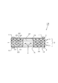
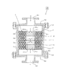
図1は、実施形態1による混合要素1Aの内部を流体Aが流れる様子を示した断面図であり、図2は、この混合要素1Aの構成部品を示す斜視図である。図3は、積層エレメント21が隣接する積層エレメント21と積層したときの第1の貫通孔22の重なりを示す平面図である。
(
FIG. 1 is a cross-sectional view showing a state in which a fluid A flows inside a mixing element 1A according to
混合要素1Aは、図1及び図2に示すように、円板から構成される積層エレメント21を複数枚(ここでは6枚)積層した積層体2を、第1の板3及び第2の板4により、例えば、適宜な位置に配された4本のボルト11及びナット12の固定手段にて両側から挟持して構成される。
第1の板3は、ボルト用の穴のみを有する円板である。第2の板4は、ボルト用の穴とともに、中央部に流体Aが流入する円形の貫通孔41を有している。第1の板3及び第2の板4は、積層エレメント21と略同一の外径を有する。
As shown in FIGS. 1 and 2, the mixing
The
積層エレメント21は、円形の第1の貫通孔22を複数有し、中央部に円形の第2の貫通孔23を有している。第2の貫通孔23の内径は、第2の板4の貫通孔41の内径と略同一、且つ略同心である。積層エレメント21が積層されることにより、第2の貫通孔23は中空部24を形成する。
各第1の貫通孔22は、その内径及びピッチが略同一である。図3に示すように、複数の第1の貫通孔22の一部は、互いに隣接する積層エレメント21の第1の貫通孔22とその位置をずらせて、部分的に重なり合うように配置され、積層エレメント21の延在する方向に連通する。複数の第1の貫通孔22の一部は、積層エレメント21の内周面及び外周面に開いている。
積層体2の両端部に対向配置されている第1の板3及び第2の板4により、積層体両端部の積層エレメント21の第1の貫通孔22は積層方向に閉じている。そのため、積層体2内部の流体Aは、積層体2両端部の積層エレメント21の第1の貫通孔22から積層方向に流出することを妨げられ、積層体2内部を積層エレメント21の延在する方向へ確実に流通する。
従って、流体Aは、混合要素1A内部を内周部から外周部へ、又はその逆に外周部から内周部へ流通させられる。以上により、複数の第1の貫通孔22間で流体Aを積層エレメント21の延在する方向に流通可能に連通するように形成される。
The
Each first through
The first through
Therefore, the fluid A is circulated in the mixing element 1A from the inner peripheral portion to the outer peripheral portion or vice versa from the outer peripheral portion to the inner peripheral portion. As described above, the fluid A is communicated between the plurality of first through
以上の混合要素1Aに、例えば、流体Aは、適宜な圧送手段により第2の板4の貫通孔41を経由して中空部24に流入する。次に、流体Aは、中空部24の内周面に開く積層エレメント21の第1の貫通孔22から、積層体2内部に流入する。次に、流体Aは、当該第1の貫通孔22に連通する他の第1の貫通孔22に流通し、さらに、他の第1の貫通孔22に連通する当該第1の貫通孔22に流通する。最終的に、流体Aは、積層体2の外周面に開く積層エレメント21の第1の貫通孔22を経由して、積層体2内部から流出する。
In the mixing element 1A described above, for example, the fluid A flows into the
以上のように、流体Aは、積層体2内部の連通する第1の貫通孔22を内周部から外周部に向かって略放射状に流動する。そして、その際に、分散、合流、反転、乱流、渦流、衝突等を繰り返すことにより高度に混合される。なお、流体Aは、上記とは逆に、積層エレメント21の積層体2の外周部から流入させ、内周部から流出させてもよい。
As described above, the fluid A flows in a substantially radial manner from the inner peripheral portion toward the outer peripheral portion through the first through
分散、合流、反転、乱流、渦流、衝突については概ね次のようである。すなわち、分散
とは、各第1の貫通孔22から隣接する第1の貫通孔22に流体Aが流出する際の分散を、合流とは複数の第1の貫通孔22から隣接する第1の貫通孔22へ流体Aが流れ込むことによる合流を、反転とは第1の貫通孔22内部での流体Aの反転をいう。また、乱流とは流体Aの不規則な流れを、渦流は強い乱流に伴って発生する渦状の流れをいい、そして、それらの流れが衝突する。
Dispersion, confluence, inversion, turbulence, vortex flow, and collision are generally as follows. That is, the dispersion is the dispersion when the fluid A flows out from each first through
中空部24は第1の貫通孔22に対して十分な大きさを有し、中空部24を構成する各積層エレメントの第2の貫通孔23は略同一の内径を有するとともに、且つ略同心である。そのため、流体Aが中空部24を流れる際の流動抵抗は積層体2内部を流れる際の流動抵抗と比較して小さく、圧力損失も小さい。従って、流体Aは、積層エレメント21の積層枚数が多い場合でも、積層方向の位置に関らず略均等に各積層エレメント21の内周部に到達し、積層体2内部を内周部から外周部へ略均等に流れる。
The
また、混合要素1A内部において、上面及び下面を他の積層エレメント21と接している積層エレメント21の第1の貫通孔22においては、当該第1の貫通孔22から上面及び下面の他の第1の貫通孔22へ流出するので、上面及び下面の他の第1の貫通孔22により流体は分散される。また、当該第1の貫通孔22へは上面及び下面の他の第1の貫通孔22から流入するので、上面及び下面の他の第1の貫通孔22からの流体が合流する。従って、混合効果が高く流体Aは高度に混合される。
特に、流量が増大して流動状態が乱流に移行すると、乱流及び渦流の効果が高くなって、上記分散及び合流に伴う流体の混合効果がより一層増大する。流量が少なくて流動状態が層流の場合でも、流体は上面及び下面に分散・合流するので高度に混合される。
In addition, in the first through
In particular, when the flow rate increases and the flow state shifts to turbulent flow, the effects of turbulent flow and vortex flow are enhanced, and the fluid mixing effect associated with the dispersion and merging is further increased. Even when the flow rate is low and the flow state is laminar, the fluid is highly mixed because it is dispersed and joined to the upper and lower surfaces.
また、積層エレメント21、第1の板3及び第2の板4が各々に分解可能なので、積層エレメント21の第1の貫通孔22に残存した残留物や異物の除去のような洗浄作業を容易にすることができる。
また、積層エレメント21、第1の板3及び第2の板4を別々に製作することができるので、混合要素1の製作が容易であり、且つ安価に製作することができる。
また、積層エレメント21として略環状の板を製作する際に、一定の厚みを有する金属板、例えばパンチングメタル等を打ち抜き加工により形成することができるので、混合要素1を、さらに安価に製作することができる。
In addition, since the
Moreover, since the
Further, when a substantially annular plate is manufactured as the
なお、本実施形態1では、積層エレメント21の第1の貫通孔22及び第2の貫通孔23、並びに第2の板4の貫通孔41を円形としているが、本発明の範囲内であればこれに限定されるものではない。また、積層エレメント21は第2の貫通孔23を中央部に、第2の板4は貫通孔41を中央部に有し、略同一径、略同心であるが、本発明の範囲内であればこれに限定されるものではない。
In the first embodiment, the first through
(混合要素1の実施形態2)
図4は、実施形態2による混合要素1Bの内部を流体Aが流れる様子を示した断面図であり、図5は、この混合要素1Bの構成部品を示す斜視図である。図6は、積層エレメント21aが他の積層エレメント21bと積層したときの第1の貫通孔22の重なりを示す平面図である。
本実施形態2による混合要素1Bが実施形態1の混合要素1Aと異なるところは、第1の板3と第2の板4との間に、第1の貫通孔22の形成パターンが異なる積層エレメント21a,21bを積層したことである。図5をも参照して、一方の積層エレメント21aでは、内周面に沿って配設される第1の貫通孔22が開放されているが、外周面では第1の貫通孔22が開放されていない。他方、積層エレメント21bでは、逆に、内周面では第1の貫通孔22が開放されていないが、外周面に沿って配設される第1の貫通孔22が開放されている。積層エレメント21a、21bの各々の第1の貫通孔22は、半径方向
及び円周方向に部分的にずれて重なり合い、積層エレメント21a,21bの延在する方向に連通する。
(
FIG. 4 is a cross-sectional view showing how the fluid A flows inside the mixing
The mixing
混合要素1Bのように構成することによっても、適宜な圧送手段により混合要素1Bに流入させられた流体Aは、第2の板4の貫通孔41を経由して中空部24に流入する。次に流体Aは、中空部24の内周面に開く積層エレメント21aの第1の貫通孔22を介して積層体2に流入し、当該積層体2内部を放射状に流通しながら、積層エレメント21a,21bの連通する第1の貫通孔22を流通することにより高度に混合される。最終的に、流体Aは、積層エレメント21bの外周面に開く第1の貫通孔22を介して積層体2から流出する。
本実施形態2の混合要素1Bにおけるその他の構成及び作用効果は、上記混合要素1における実施形態1の混合要素1Aと同様である。
Also by configuring like the
Other configurations and operational effects of the mixing
(混合要素1の実施形態3)
図7は、実施形態3による混合要素1Cの内部を流体Aが流れる様子を示した断面図であり、図8は、この混合要素1Cにおける積層エレメント21cを示す斜視図である。
本混合要素1Cが、実施形態1による混合要素1Aと異なるところは、図7及び図8に示すように、複数の積層エレメント21cが、中央部には第2の貫通孔23を設けずに第1の貫通孔22を全面に有し、且つ外周部に第1の貫通孔22が開放しない枠部25(図8参照)を有していることである。また、各第1の貫通孔22は、四角形状に形成されている(図8参照)。さらに、第1の板3の外周形状は、当該板に重ね合わされた積層エレメント21cの外周部分の第1の貫通孔22が開放されるように、積層エレメント21cよりも小径に形成されている(図7参照)。
(
FIG. 7 is a cross-sectional view showing a state where the fluid A flows inside the mixing
The mixing
混合要素1Cをこのように構成することによっても、適宜な圧送手段により混合要素1Cに流入させられた流体Aは、第2の板4の貫通孔41を介して積層体2に流入し、積層体2内部を放射状に流通しながら、積層エレメント21cの連通する第1の貫通孔22を流通することにより高度に混合される。最終的に、流体Aは、積層体2の一端に配設された第1の板3の外周部に開く第1の貫通孔22を介して流出する。
Also by configuring the mixing
このように、実施形態3による混合要素1Cによれば、第1の貫通孔22を積層エレメント21cの全面に形成するため、中央部に第2の貫通孔23を設ける必要が無く、製作が容易である。
本実施形態3の混合要素1Cにおけるその他の構成及び作用効果は、上記実施形態1の混合要素1Aと同様である。
As described above, according to the
Other configurations and operational effects of the mixing
(混合要素1の変形例)
なお、本発明に係る混合要素1は、上記各実施形態1〜3に限定されず、種々の変更を施すことが可能である。
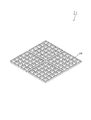
例えば、積層エレメント21の第1の貫通孔22は、円形に限らず図9(a)〜(d)に示すように、正四角形、三角形、六角形、長方形等の多角形形状としてもよい。第1の貫通孔22を多角形形状とすることで、積層エレメント21の開口率が大きくなるので、混合要素1の流動抵抗を小さくすることができる。
(Modification of mixing element 1)
In addition, the mixing
For example, the 1st through-
さらに、上記各混合要素の実施形態において積層エレメント21として略環状の板を製作する場合には、一定の厚みを有する金属板、例えばパンチングメタル等を打ち抜き加工等により穿設して短時間で大量に製作することができる。これにより、混合要素1を安価に製作することができる。
また、積層エレメント21、第1の板3及び第2の板4等は、各種形状の分割構造とすることができる。この場合、大型の混合要素1であっても容易に製作することができる。
図10に示すように、積層エレメント21が環状の形状を有する場合には、扇形形状の分割体26による分割構造とすることができる。また、図11に示すように、積層エレメント21が四角形の場合は、矩形形状の分割体26による分割構造とすることができる。
また、積層エレメント21を光触媒を担持したものとすることができる。これによれば、各板に付着した流体の残留物や異物を光触媒の作用によって短時間に容易に分解することができるので、混合装置の運転終了後の洗浄等のメンテナンスが容易になる。
Further, when a substantially annular plate is manufactured as the
Moreover, the
As shown in FIG. 10, when the
Moreover, the
(混合装置の実施形態1)
図12は、混合装置の実施形態1による流体Aが流れる様子を示した断面図である。
本実施形態1による混合装置5Aは、図12に示すように、フランジ53を有する円筒状ケーシング50に、入口51及び出口52を有する外周円板状のフランジ54が着脱自在に装着している。円筒状ケーシング50の内部には、前記した円板から構成される積層エレメント21を複数枚(ここでは3枚)重ね合わせた積層体2が4つ配設されている。
ケーシング50の入口51側には、中央部に貫通孔41を有し、ケーシング50の内径と略同一の外径を有する第2の板4が配設され、その下面に積層エレメント21の第1積層体2aが配設されている。第1積層体2aの下面には積層エレメント21の外径と略同一の外径を有する第1の板3が配設されている。続いて第2積層体2b、第2の板4、第3積層体2c、第1の板3、第4積層体2d、第2の板4が、順次配設されている。
図12に示す混合装置では、各第2の板4の外径がケーシング50の内径と略同一であり、混合要素1がケーシング50内に固定されるが、第1の板3、第2の板4及び積層体2による混合要素1をボルトとナットのような固定手段で固定するようにしてもよい。
(
FIG. 12 is a cross-sectional view illustrating a state in which the fluid A flows according to the first embodiment of the mixing device.
In the
On the
In the mixing apparatus shown in FIG. 12, the outer diameter of each
積層エレメント21は、混合要素1の実施形態の混合要素1A及び1Bと同様に、第1の貫通孔22を複数有し、中央部に円形の第2の貫通孔23を有している。積層エレメント21の第2の貫通孔23の内径は、第2の板4の貫通孔41の内径と略同一、且つ略同心である。積層エレメント21が積層されることにより、第2の貫通孔23は中空状の空間部である第1中空部24a、第2中空部24b、第3中空部24c及び第4中空部24dを構成する。各々の中空部24a〜24dは、各々積層体2a〜2dに対応する中空部24である。
ケーシング50の内周部と、第1積層体2a及び第2積層体2bの外周部との間には第1環状空間部55aが、並びに、第3積層体2c及び第4積層体2dの外周部との間には第2環状空間部55bが形成される。
Like the mixing
Between the inner peripheral part of the
また、各積層体2a〜2d内部において、混合要素1A及び1Bの実施形態1、2と同様に、複数の第1の貫通孔22の一部は、積層エレメント21の延在する方向に連通し、また、積層エレメント21の内周面及び外周面に開いている。
各積層体2a〜2dの両端部に対向配置されている第1の板3及び第2の板4により、各積層体2a〜2dの両端部の第1の貫通孔22は積層方向に閉じている。そのため、積層体2内部の流体は、各積層体2a〜2dの両端部の第1の貫通孔22から積層方向に流出することを妨げられ、積層体2a〜2d内部を積層エレメント21の延在する方向へ確実に流通する。
In addition, in each of the
The
以上の構成を有する混合装置5Aに、例えば、流体Aは、適宜な圧送手段により入口51から流入し、第1中空部24aに流入する。続いて、流体Aは、第1中空部24aの内周面に開く第1の貫通孔22から第1積層体2a内部に流入し、連通する第1の貫通孔22を外周方向へ流通する。続いて、流体Aは、第1積層体2aの外周面に開く第1の貫通孔22から流出し、第1環状空間部55aに流入する。
In the
続いて、流体Aは、第2積層体2bの外周面に開く第1の貫通孔22から第2積層体2b内部に流入し、連通する第1の貫通孔22を内周方向へ流通する。そして、流体Aは、第2中空部24bの内周面に開く第1の貫通孔22から流出し、第2中空部24bに流入する。
Subsequently, the fluid A flows into the second
その後、流体Aは、第3中空部24c→第3積層体2c→第2環状空間部55b→第4積層体2d→第4中空部24dを経由して出口52から流出する。以上のように、流体Aは、各積層体2a〜2dの内部を内周部から外周部へ、又は外周部から内周部へ放射状に流通しながら、連通する第1の貫通孔22を流通することにより高度に混合される。以上により、混合装置5Aの入口51から流入した流体Aは、高度に混合されて出口52から流出する。
Thereafter, the fluid A flows out from the
本混合装置5Aによれば、各積層体2a〜2dの両端部に対向配置されている第1の板3及び第2の板4により、流体Aが積層体2内部を流れる方向を、内周部から外周部へ、又はその逆に、外周部から内周部へと変えることができる。そうすると、流体Aは、より多くの連通する第1の貫通孔22を流通するので、さらに流体Aの混合度を高めることができる。
According to the
また、各中空部24a〜24dは第1の貫通孔22に対して十分な大きさを有し、中空部24を構成する各積層エレメントの第2の貫通孔23は略同一の内径を有するとともに、且つ略同心である。そのため、流体Aが各中空部24a〜24dを流れる際の流動抵抗は各積層体2a〜2d内部を流れる際の流動抵抗と比較して小さく、圧力損失も小さい。従って、流体Aは、積層エレメント21の積層枚数が多い場合でも、積層方向の位置に関らず略均等に各積層エレメント21の内周部に到達し、各積層体2a〜2d内部を内周部から外周部へ、又はその逆に外周部から内周部へ略均等に流れる。
Moreover, each hollow part 24a-24d has sufficient magnitude | size with respect to the 1st through-
各環状空間部55a,55bから積層体2内部への流体Aの流入についても、上記各中空部24a〜24dについてのものと同様である。
The flow of the fluid A from the
さらに、本混合装置5Aによれば、入口51及び出口52を有するケーシング50の内部で流体Aを混合することができるため、インライン静止型混合装置としての使用が可能であって、流体Aを連続的に混合することができる。
また、積層エレメント21、第1の板3及び第2の板4の外周形状を円形とすることにより、ケーシング50を円筒形状とすることができるため、ケーシング50の耐圧を高くすることができる。従って、流体Aを高圧条件下で混合することができる。
本実施形態1による混合装置5Aにおけるその他の構成及び作用効果は、上記混合要素1の実施形態1の混合要素1Aと同様である。
Furthermore, according to the
Moreover, since the
Other configurations and operational effects of the
(混合装置の実施形態2)
図13は、混合装置5の実施形態2による流体Aが流れる様子を示した断面図である。
本実施形態2による混合装置5Bでは、図13に示すように、各積層体2a〜2dを構成する積層エレメント21の外径がケーシング50内径と略同一であって、他の構成は上記混合装置5の実施形態1と同じである。
この混合装置5Bでは、混合要素1とケーシング50との間に環状空間部55a,55bを有しておらず、第1の板3の外径は、第2の板4や積層体2の外径よりも小さい。従って、流体Aは、第1積層体2aと第2積層体2bとの間、第3積層体2cと第4積層体2dとの間では、外周部で互いに連通する第1の貫通孔22間で流通する。
このような構成によっても、流体Aは、各積層体2a〜2d内部の連通する第1の貫通孔22を積層エレメント21の延在する方向に流通することにより混合される。
本実施形態2は、積層エレメント21の外径及び第2の板4の外径がケーシング50の内径と略同一であるため、積層エレメント21及び第2の板4のケーシング50の内部への設置が容易である。
(
FIG. 13 is a cross-sectional view illustrating a state in which the fluid A according to the second embodiment of the mixing device 5 flows.
In the
In the
Even with such a configuration, the fluid A is mixed by flowing through the first through
In the second embodiment, since the outer diameter of the
本実施形態2における混合装置5Bのその他の作用効果は、上記混合装置5の実施形態1における混合装置5Aの作用効果と同様である。
Other functions and effects of the
(混合装置の実施形態3)
図14は、混合装置5の実施形態3による流体Aが流れる様子を示した断面図である。
本実施形態3による混合装置5Cでは、図14に示すように、第1積層体2a〜第4積層体2dを構成する積層エレメント21が第2の貫通孔23を有さない点を除いては、混合装置5の実施形態2と同じである。このような構成によっても、流体Aは、各積層体2a〜2d内部の連通する第1の貫通孔22を積層エレメント21の延在する方向に流通することにより混合される。
本実施形態3は、積層エレメント21の外径及び第2の板4の外径が、ケーシング50の内径と略同一であるので、積層エレメント21及び第2の板4のケーシング50内部への設置が容易である。また、積層エレメント21が第2の貫通孔23を有さないので、製作が容易である。例えば、図8に示される積層エレメント21cが本実施形態3の一部に使用される。
(
FIG. 14 is a cross-sectional view showing a state in which the fluid A according to the third embodiment of the mixing device 5 flows.
In the mixing device 5C according to the third embodiment, as shown in FIG. 14, except that the
In the third embodiment, since the outer diameter of the
本実施形態3における混合装置5Cのその他の作用効果は、上記混合装置5の実施形態1における混合装置5Aの作用効果と同様である。
Other functions and effects of the mixing device 5C according to the third embodiment are the same as those of the
(混合装置の変形例)
本発明に係る混合装置5は、混合要素1の変形例と同様に上記の混合装置5の各実施形態1〜3に限定されない。本発明の範囲内で変形して実施することができる。
例えば、積層エレメント21、第1の板3及び第2の板4の外周形状は特に円形には限定されない。外周形状が円形でなくても、いずれの発明を実施する上においては何の支障もないからである。工場の排気ガス処理装置のような断面が長方形状の管路に本混合方法を適用するに際しては、第2の板4の外側形状を長方形状の管路の内側形状と略同一にすれば良い。
(Modification of mixing device)
The mixing apparatus 5 which concerns on this invention is not limited to each Embodiment 1-3 of said mixing apparatus 5 similarly to the modification of the mixing
For example, the outer peripheral shape of the
(その他)
混合される流体Aは、気体や液体に限定されるものではなく、液体と固体との混合物あるいはその他であってもよい。特に、液体に粒状物質を溶解させる場合には、従来の円板に前面開放の多角形状の小室を有する導流単位体では、小室に閉塞した粒状物質の除去が困難であったが、本発明に係る混合装置5は分解可能な構造であるため、そのような場合でも閉塞した粒状物質の除去が容易である。
(Other)
The fluid A to be mixed is not limited to gas or liquid, but may be a mixture of liquid and solid or others. In particular, when dissolving a granular substance in a liquid, it is difficult to remove the granular substance blocked in the small chamber in the conventional flow guide unit having a polygonal small chamber open on the front surface of the disk. Since the mixing apparatus 5 which concerns on this is the structure which can be decomposed | disassembled, removal of the obstruct | occluded granular material is easy even in such a case.
用途としては、流体の濃度を均一にする用途以外にも、例えば、温度が異なる同一種の流体を混合して均一な温度とする用途にも適用できる。 As an application, in addition to an application for making the concentration of the fluid uniform, for example, it can be applied to an application for mixing the same kind of fluids having different temperatures to obtain a uniform temperature.
(攪拌装置の実施形態1)
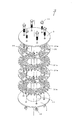
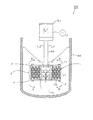
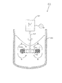
図15は、攪拌装置6の実施形態1による流体Bが攪拌装置6A内部を循環する様子を示した断面図である。図16は、この攪拌装置6Aに用いられる混合要素1の平面図である。図17は、この混合要素1の構成部品を示す斜視図である。なお、図15及び図16に示された内板7は、図17では省略されている。
攪拌装置6Aは、図15に示すように、混合要素1、駆動源61、回転軸62及び攪拌槽63を備えている。駆動源61は、混合要素1を回転駆動するものであり、本実施形態では、供給電源Pから電力が供給されることで回転駆動する駆動モータである。回転軸62は、駆動源61に連結された状態で、混合要素1を支持するものであり、また、攪拌槽63の内部には、流体Bが収容されている。
(
FIG. 15 is a cross-sectional view showing a state where the fluid B according to the first embodiment of the stirring device 6 circulates inside the stirring
As shown in FIG. 15, the stirring device 6 </ b> A includes a mixing
図17を参照して、混合要素1は、図1及び図2に示す積層エレメント21と同様に、略環状の形状を有する積層エレメント21を複数枚(ここでは6枚)を重ね合わせた積層エレメント21からなる積層体2を、第1の板3及び第2の板4により、適宜な位置に配された4本のボルト11及びナット12の締結部材にて両側から挟持して構成される。
第1の板3は、ボルト用の穴と、4つの貫通孔31とを有する円板である。第2の板4は、ボルト用の穴とともに、中央部に流体Aが流入する円形の貫通孔41を有する。第1の板3及び第2の板4は、積層エレメント21と略同一の外径を有する。
積層エレメント21は、円形の第1の貫通孔22を複数有し、中央部に攪拌槽63内を循環する流体Bが流入する円形の第2の貫通孔23を有する。積層エレメント21の第2の貫通孔23の内径は、第2の板4の貫通孔41の内径と略同一、且つ略同心である。積層エレメント21が積層されることにより、第2の貫通孔23は中空部24を形成する。中空部24の内周面には、積層エレメント21の積層方向に伸びる内板7が4枚配設されている。
本混合要素1のその他の構成は、混合要素1の実施形態1における混合要素1Aと同様である。
Referring to FIG. 17, the mixing
The
The
Other configurations of the mixing
駆動モータ61により混合要素1が回転駆動すると、混合要素1の積層体2内部の流体Bは、遠心力の作用により半径方向外方に向けて付勢される。付勢された流体Bは、積層体2内部の連通する第1の貫通孔22を内周部から外周部に向かって略放射状に流通し、外周面に開く第1の貫通孔22から外方へ吐出される。
一方、図15を参照して、攪拌槽63内の流体Bは、混合要素1の下端部の第2の板4の貫通孔41及び上端部の第1の板3の4つの貫通孔31を介して積層体2内部の中空部24に吸い込まれる。吸い込まれた流体Bは、中空部24の内周面に開く第1の貫通孔22を経由して、積層体2内部に流入する。そして、混合要素1の回転動作による遠心力の作用により半径方向外方に向けて付勢され、上記のように外周面に開く第1の貫通孔22から外方へ吐出される。
そして、流体Bは、積層体2内部を内周部から外周部に向かって略放射状に流動する際に、連通する第1の貫通孔22を流通することにより高度に混合される。
When the mixing
On the other hand, referring to FIG. 15, the fluid B in the stirring
The fluid B is highly mixed by flowing through the first through
本攪拌装置6Aによれば、積層エレメント21の積層枚数を多くすることにより、流体が流通する混合要素1内部の連通する第1の貫通孔22が多くなるので、流体Bの混合時間を短くすることができる。
According to the
また、中空部24には、内周に積層エレメント21の積層方向に伸びる内板7が配設されており、混合要素1の回転動作により、内板7の回転方向と反対側の面近傍に強力な吸い込み流れが発生する。そのため、中空部24に流入する流体Bの流量がより多くなる。従って、さらに攪拌槽63内部を循環する流体Bの流量が多くなり、より混合効果を高めることができる。
また、混合要素1の底部の第2の板4の下面に、鉛直方向に放射状に伸びる外板を設けてもよい。これにより、当該外板の回転方向と反対側の面近傍に強力な吸い込み流れが発生し、中空部24に流入する流体Bの流量が多くなる。従って、さらに攪拌槽63内を循環する流体Bの流量が多くなり、より混合効果を高めることができる。
また、混合要素1を攪拌槽63の底部近くに配設する場合には、混合要素1を支持する回転軸62及び駆動源61を攪拌槽63の下部に配設しても良い。この場合は、攪拌槽63底部の回転軸62が挿通される部分に適宜なシール機構が設けられる。
また、積層体2の中空部24に設けた内板7を設けない構成としてもよい。
Further, in the
Further, an outer plate extending radially in the vertical direction may be provided on the lower surface of the
When the mixing
Moreover, it is good also as a structure which does not provide the inner board 7 provided in the
なお、本発明に係る攪拌装置6Aは、混合要素1の変形例と同様に上記の攪拌装置6Aの実施形態1に限定されない。
本実施形態1における攪拌装置6Aのその他の作用効果は、上記混合要素1の実施形態1における混合要素1Aの作用効果と同様である。
Note that the
Other functions and effects of the
(攪拌装置の実施形態2)
図18は、攪拌装置6の実施形態2による流体Bが攪拌装置6B内部を循環する様子を示した断面図である。図19は、攪拌翼80Aにおけるパドル翼8aの斜視図である。図20は、パドル翼8aに混合要素1が配設された攪拌翼80Aの平面図及び断面図である。
(
FIG. 18 is a cross-sectional view showing a state where the fluid B according to the second embodiment of the stirring device 6 circulates inside the stirring
本実施形態2による攪拌装置6Bでは、図18に示すように、攪拌槽63内に混合要素1を具備する攪拌翼80Aが配設されている点を除いて、攪拌装置6の実施形態1と同じである。攪拌翼80Aは、図20に示すように、回転軸62を設けたパドル翼8aと、このパドル翼8aに具備する混合要素1とを備える。パドル翼8aは、図19に示すように、回転軸62に設置された4枚の羽根81を有する。混合要素1は、第1の板3、積層体2を構成する積層エレメント21、第2の板4が積層方向に分解可能に固定されるとともに、円周方向に複数(4個)の扇形形状の分割体26Aに分割可能に固定されている。分割体26Aは、第1の板3、積層体2及び第2の板4の各々が内周側を円弧状に切り欠いた扇形に形成されて、積層体2が第1の板3及び第2の板4の間に挟持されるようにボルト11及びナット12等の固定手段で固定されている。これら扇形形状の分割体26Aがパドル翼8aの隣り合った羽根81の間に配置されて、適宜の固定手段(図示せず)により羽根81に固定されている。これにより、パドル翼8aには4個の扇形形状の分割体26Aが円周方向に配置されて、内側には両端側(図20(b)の上下端側)に開放する中空部24を有する混合要素1が形成される。なお、本混合要素1のその他の構成は、混合要素1の実施形態1における混合要素1Aと同様である。
In the
再び図18を参照して、この攪拌装置6Bによれば、駆動モータ61により攪拌翼80Aが回転駆動されると、上述の攪拌装置6の実施形態1と同様に、攪拌槽63内の流体Bは、パドル翼8aの回転動作によって中空部24の上下の開放部から中空部24内に吸込まれるとともに、回転による円周方向への吸込流により中空部24と連通する第1の貫通孔22を経由して積層体2内部に流入される。積層体2内部に流入した流体Bは、パドル翼8a及び混合要素1の回転動作による遠心力の作用により、積層体2内部に連通する第1の貫通孔22を半径方向外方に向けて付勢されて流動され、そして、混合要素1の外周面に開く第1の貫通孔22から外方へ吐出される。このように、この攪拌翼80Aによれば、流体Bは混合要素1により高度に混合されるので、パドル翼8aによる混合をより効率的にすることができる。
なお、本実施形態2における攪拌装置6Bのその他の作用効果は、上記攪拌装置6の実施形態1における攪拌装置6Aの作用効果と同様である。
Referring to FIG. 18 again, according to the
In addition, the other effect of the
(攪拌装置の実施形態3)
図21は、攪拌装置6の実施形態3による流体Bが攪拌装置6C内部を循環する様子を示した断面図である。図22は、攪拌翼80Bにおけるディスクタービン翼8bの斜視図である。図23は、ディスクタービン翼8bに混合要素1が配設された攪拌翼80Bの平面図及び断面図である。
(
FIG. 21 is a cross-sectional view showing a state where the fluid B according to the third embodiment of the stirring device 6 circulates inside the stirring
本実施形態3による攪拌装置6Cでは、図21に示すように、攪拌槽63内に混合要素1を具備する攪拌翼80Bが配設されている点を除いて、攪拌装置6の実施形態1と同じである。攪拌翼80Bは、図23に示すように、回転軸62を設けたディスクタービン翼8bと、このディスクタービン翼8bに具備する混合要素1とを備える。ディスクタービン翼8bは、図22に示すように、回転軸62に取り付けられたディスク82と、このディスク82の外周部に設けられた6枚の羽根83とを有する。混合要素1は、第1の板3、積層体2を構成する積層エレメント21、第2の板4が積層方向に分解可能にボルト11及びナット12等の固定手段で固定されている。この混合要素1は、中空部24内にディスクタービン翼8bの6枚の羽根83が配設されるように回転軸62に取り付けられている。これにより、ディスクタービン翼8bの外周に混合要素1が配置される。なお、この混合要素1は、第1の板3が4つの貫通孔31を有する円板で形成されている点を除いて、その構成は、混合要素1の実施形態1における混合要素1Aと同様である。
In the
再び図21を参照して、この攪拌装置6Cによれば、駆動モータ61により攪拌翼80Bが回転駆動されると、上述の攪拌装置6の実施形態1と同様に、攪拌槽63内の流体Bは、ディスクタービン翼8bの回転動作によって中空部24の上下の開放部から中空部24内に吸込まれるとともに、回転による円周方向への吸込流により中空部24と連通する第1の貫通孔22を経由して積層体2内部に流入される。積層体2内部に流入した流体Bは、ディスクタービン翼8b及び混合要素1の回転動作による遠心力の作用により、積層体2内部に連通する第1の貫通孔22を半径方向外方に向けて付勢されて流動され、そして、混合要素1の外周面に開く第1の貫通孔22から外方へ吐出される。このように、この攪拌翼80Bによれば、流体Bは混合要素1により高度に混合されるので、ディスクタービン翼8bによる混合をより効率的にすることができる。
なお、本実施形態3における攪拌装置6Cのその他の作用効果は、上記攪拌装置6の実施形態1における攪拌装置6Aの作用効果と同様である。
Referring to FIG. 21 again, according to the
In addition, the other effect of the
本発明において攪拌翼80を備えた攪拌装置6は上記攪拌装置6の実施形態2,3に限定されず、例えば、図20に示す攪拌翼80Aは、扇形形状の分割体26Aによる混合要素1に代えて図23に示す環状の混合要素1を用い、この環状の混合要素1の中空部24内に適宜の間隔を保ってパドル翼8aが配設されてもよい。また、羽根81の数も適宜に設定してもよく、パドル翼8aに限らず傾斜パドル翼としてもよい。
また、図23に示す攪拌翼80Bは、環状の混合要素1に代えて図20に示す扇形形状の分割体26Aをディスクタービン翼8bの隣り合った羽根83の間に配設されてもよい。ディスクタービン翼8bの羽根83は、図22に示すディスク82の半径方向に真っ直ぐ配置したものに限らず半径方向から一定角度傾斜した傾斜タービン翼や羽根を湾曲させたホローブレイド翼等としてもよく、また、羽根83の数も適宜に設定することができる。
In the present invention, the stirring device 6 provided with the stirring blade 80 is not limited to the second and third embodiments of the stirring device 6 described above. For example, the
Further, in the
(その他)
積層エレメント21、第1の板3及び第2の板4は簡単な構造を有するので、従来の導流単位体のような構造では製作が難しいセラミックス等の材料によっても製作することが可能である。従って、耐食性や耐熱性が必要とされる用途にも混合要素1、混合装置5、混合方法、攪拌装置6及び攪拌方法を適用することができる。
(Other)
Since the
また、大きな空間を必要とせず、又、管路中に配設することができるので、例えば、ディーゼル自動車の排気ガスラインのように設置空間が限られている場所に混合要素1、混合装置5、混合方法を適用することもできる。この場合、排気ガスと還元剤の混合を良好に行うことにより、排気ガス中の窒素酸化物の分解率が向上する。従って、排気ガス中の窒素酸化物の濃度を低下するので、地球環境の向上に貢献することができる。
Moreover, since a large space is not required and it can be arranged in a pipe line, for example, the mixing
また、化学プラントで数種類の流体を混合して反応させる触媒反応器入口に混合要素1、混合装置5、混合方法を適用することもできる。この場合には、触媒層に供給される流体の濃度分布が小さくなるので、反応率が向上し、目的とする生成物質の収率の向上が可能である。その結果、化学プラント全体のエネルギー効率が向上して二酸化炭素の発生を減少させることができるので、やはり、地球環境の向上に貢献することができる。
Moreover, the mixing
以上に開示された実施の形態はすべての点で例示であって制限的なものではないと考慮されるべきである。本発明の範囲は、以上の実施の形態ではなく、特許請求の範囲によって示され、特許請求の範囲と均等の意味及び範囲内でのすべての修正や変形を含むものである。 The embodiment disclosed above should be considered as illustrative in all points and not restrictive. The scope of the present invention is shown not by the above-described embodiments but by the scope of claims for patent, and includes all modifications and variations within the scope and meaning equivalent to the scope of claims for patent.
1 混合要素
2 積層体
3 第1の板
4 第2の板
5 混合装置
6 攪拌装置
7 内板
8a パドル翼
8b ディスクタービン翼
21 積層エレメント
22 第1の貫通孔
23 第2の貫通孔
24 中空部
41 貫通孔
55 環状空間部
A,B 流体
DESCRIPTION OF
Claims (14)
前記積層エレメントは、複数の第1の貫通孔を有し、
前記第2の板は、前記積層エレメントの少なくとも1つの第1の貫通孔に連通する貫通孔を有し、
前記積層エレメントは、前記第1の貫通孔の一部又は全部が、隣接する積層エレメントの第1の貫通孔とその位置をずらせて部分的に重なり合うように配置され、且つ隣接する積層エレメントの第1の貫通孔との間で流体を積層エレメントの延在する方向に流通可能に連通するように配置されていることを特徴とする混合要素。 A laminated body in which a plurality of laminated elements are laminated, and a first plate and a second plate arranged to face each other with the laminated body interposed therebetween,
The laminated element has a plurality of first through holes,
The second plate has a through hole communicating with at least one first through hole of the laminated element,
The laminated element is arranged so that a part or all of the first through holes partially overlap with the first through holes of the adjacent laminated elements, and the first through holes of the adjacent laminated elements A mixing element, wherein the mixing element is arranged to communicate with a through-hole so that fluid can flow in a direction in which the laminated element extends.
前記複数の積層エレメント、前記第1の板及び前記第2の板は、分解可能に固定されていることを特徴とする混合要素。 The mixing element according to claim 1,
The mixing element, wherein the plurality of laminated elements, the first plate, and the second plate are fixed so as to be disassembled.
前記複数の積層エレメント、前記第1の板及び前記第2の板は、分割可能であることを特徴とする混合要素。 The mixing element according to claim 1 or 2,
The mixing element, wherein the plurality of laminated elements, the first plate, and the second plate are separable.
前記積層エレメントは、複数の貫通孔を有する金属板を穿設して形成されていることを特徴とする混合要素。 A mixing element according to claims 1-3.
The laminated element is formed by drilling a metal plate having a plurality of through holes.
前記第1の板の外側形状が、前記第2の板の貫通孔よりも大きいことを特徴とする混合要素。 The mixing element according to any one of claims 1 to 4,
A mixing element characterized in that an outer shape of the first plate is larger than a through hole of the second plate.
前記積層エレメントは、複数の第1の貫通孔を有し、
前記第2の板は、前記積層エレメントの少なくとも1つの第1の貫通孔に連通する貫通孔を有し、
前記積層エレメントは、前記第1の貫通孔の一部又は全部が、隣接する積層エレメントの第1の貫通孔との間で流体を積層エレメントの延在する方向に流通可能に連通するように配置され、
前記積層エレメントは、第1の貫通孔より大きい第2の貫通孔を有し、且つ前記第2の貫通孔が積層方向に連通して前記積層体に中空部が形成されるように配置されており、
前記第2の板の貫通孔が前記中空部を介して前記積層エレメントの少なくとも1つの第1の貫通孔に連通されていることを特徴とする混合要素。 A laminated body in which a plurality of laminated elements are laminated, and a first plate and a second plate arranged to face each other with the laminated body interposed therebetween,
The laminated element has a plurality of first through holes,
The second plate has a through hole communicating with at least one first through hole of the laminated element,
The laminated element is arranged such that a part or all of the first through-hole communicates with a first through-hole of an adjacent laminated element so that fluid can flow in the direction in which the laminated element extends. And
The laminated element has a second through hole larger than the first through hole, and is arranged such that the second through hole communicates in the laminating direction to form a hollow portion in the laminated body. And
The mixing element, wherein a through hole of the second plate communicates with at least one first through hole of the laminated element through the hollow portion.
前記混合要素における第1の板は、前記ケーシング内側形状よりも小さい外側形状を有し、
前記混合要素における第2の板は、前記ケーシング内側形状と略同一の外側形状を有し、且つ当該第2の板の外側面が前記ケーシング内側面と略内接されていることを特徴とする混合装置。 A mixing element according to any one of claims 1 to 6, and a casing having an inlet and an outlet for accommodating the mixing element,
The first plate of the mixing element has an outer shape smaller than the casing inner shape;
The second plate of the mixing element has an outer shape that is substantially the same as the inner shape of the casing, and the outer surface of the second plate is substantially inscribed with the inner surface of the casing. Mixing device.
前記混合要素内部に流入した流体を、前記積層エレメントの延在する方向に前記第1の貫通孔に流通させて前記混合要素外部に流出させることを特徴とする混合方法。 A method of mixing fluid with the mixing device according to claim 7,
The mixing method, wherein the fluid that has flowed into the mixing element is caused to flow through the first through hole in a direction in which the laminated element extends to flow out of the mixing element.
前記混合要素は、前記積層体に形成される中空部の内側に、前記積層エレメントの積層方向に伸びる内板が配設されていることを特徴とする攪拌装置。 The stirrer according to claim 9,
The mixing element is provided with an inner plate extending in a stacking direction of the stacked elements inside a hollow portion formed in the stacked body.
前記混合要素が、自己の回転動作により、前記第2の板の貫通孔を介して前記積層エレメントの第2の貫通孔から混合要素内部に流入した流体を、前記積層エレメントの複数の第1の貫通孔を介して混合要素の外側部から流出させることを特徴とする攪拌方法。 A method of stirring fluid with the stirring device according to claim 9 or 10,
The mixing element causes the fluid that has flowed into the mixing element from the second through-hole of the stacked element through the through-hole of the second plate by the self-rotating operation, and the plurality of first elements of the stacked element An agitation method, wherein the mixing element is caused to flow out from an outer portion of the mixing element through a through hole.
前記攪拌翼の回転動作により、前記攪拌翼に具備された混合要素が、前記第2の板の貫通孔を介して前記積層エレメントの第2の貫通孔から混合要素内部に流入した流体を、前記積層エレメントの複数の第1の貫通孔を介して混合要素の外側部から流出させることを特徴とする攪拌方法。 A method of stirring fluid with the stirring blade according to claim 12,
Due to the rotation operation of the stirring blade, the mixing element provided in the stirring blade causes the fluid flowing into the mixing element from the second through hole of the laminated element through the through hole of the second plate, An agitation method, wherein the mixing element is caused to flow out from the outer side of the mixing element through the plurality of first through holes of the laminated element.
Priority Applications (9)
| Application Number | Priority Date | Filing Date | Title |
|---|---|---|---|
| JP2009132802A JP5500575B2 (en) | 2008-06-16 | 2009-06-02 | Mixing element, mixing device, mixing method, stirring blade, stirring device, and stirring method |
| KR1020177011006A KR101853241B1 (en) | 2008-06-16 | 2009-06-16 | Mixing element, mixing device, agitation blade, mixing machine, mixing system and reaction device |
| PCT/JP2009/060922 WO2009154188A1 (en) | 2008-06-16 | 2009-06-16 | Mixing element, mixing device, agitation blade, mixing machine, mixing system and reaction device |
| US12/999,102 US8715585B2 (en) | 2008-06-16 | 2009-06-16 | Mixing unit, mixing device, agitation impeller, pump mixer, mixing system and reaction device |
| KR1020107028585A KR101740736B1 (en) | 2008-06-16 | 2009-06-16 | Mixing element, mixing device, agitation blade, mixing machine, mixing system and reaction device |
| EP09766636.6A EP2286905B1 (en) | 2008-06-16 | 2009-06-16 | Mixing element, mixing device, agitation blade, mixing machine, mixing system and reaction device |
| US14/203,188 US9656223B2 (en) | 2008-06-16 | 2014-03-10 | Mixing unit and device, fluid mixing method and fluid |
| US15/484,352 US10376851B2 (en) | 2008-06-16 | 2017-04-11 | Mixing unit and device, and fluid mixing method |
| US16/051,577 US10589236B2 (en) | 2008-06-16 | 2018-08-01 | Mixing unit and device, and fluid mixing method |
Applications Claiming Priority (3)
| Application Number | Priority Date | Filing Date | Title |
|---|---|---|---|
| JP2008157237 | 2008-06-16 | ||
| JP2008157237 | 2008-06-16 | ||
| JP2009132802A JP5500575B2 (en) | 2008-06-16 | 2009-06-02 | Mixing element, mixing device, mixing method, stirring blade, stirring device, and stirring method |
Related Child Applications (1)
| Application Number | Title | Priority Date | Filing Date |
|---|---|---|---|
| JP2014042671A Division JP5887688B2 (en) | 2008-06-16 | 2014-03-05 | Technology for mixing or stirring fluids |
Publications (2)
| Publication Number | Publication Date |
|---|---|
| JP2010023026A JP2010023026A (en) | 2010-02-04 |
| JP5500575B2 true JP5500575B2 (en) | 2014-05-21 |
Family
ID=41729364
Family Applications (2)
| Application Number | Title | Priority Date | Filing Date |
|---|---|---|---|
| JP2009132802A Active JP5500575B2 (en) | 2008-06-16 | 2009-06-02 | Mixing element, mixing device, mixing method, stirring blade, stirring device, and stirring method |
| JP2014042671A Active JP5887688B2 (en) | 2008-06-16 | 2014-03-05 | Technology for mixing or stirring fluids |
Family Applications After (1)
| Application Number | Title | Priority Date | Filing Date |
|---|---|---|---|
| JP2014042671A Active JP5887688B2 (en) | 2008-06-16 | 2014-03-05 | Technology for mixing or stirring fluids |
Country Status (1)
| Country | Link |
|---|---|
| JP (2) | JP5500575B2 (en) |
Families Citing this family (11)
| Publication number | Priority date | Publication date | Assignee | Title |
|---|---|---|---|---|
| WO2013137136A1 (en) * | 2012-03-13 | 2013-09-19 | アイセル株式会社 | Mixed element, device using same, fluid mixing method, and fluid |
| WO2012029663A1 (en) * | 2010-08-30 | 2012-03-08 | 株式会社Mgグローアップ | Nitrogen-treated-water generating device, nitrogen-treated-water generating method, nitrogen-treated water, and processing method for maintaining freshness of fresh fishery products processed by means of nitrogen-treated water |
| JP5654291B2 (en) * | 2010-08-30 | 2015-01-14 | 株式会社Mgグローアップ | Static fluid mixing device |
| DK2529829T3 (en) * | 2011-06-01 | 2014-01-20 | Vakumix Ruehr Und Homogenisiertechnik Ag | Dispersion rotor for homogenizing liquid media |
| JP2013135834A (en) * | 2011-10-24 | 2013-07-11 | Mg Grow Up:Kk | Display stand |
| JP6387497B2 (en) * | 2012-07-27 | 2018-09-12 | アイセル株式会社 | Substance production method |
| JP6046465B2 (en) * | 2012-11-22 | 2016-12-14 | 株式会社Mgグローアップ | Static fluid mixing device |
| JP2016064400A (en) * | 2014-04-04 | 2016-04-28 | アイセル株式会社 | Technique for mixing or agitating fluid |
| JP2016215192A (en) * | 2015-05-15 | 2016-12-22 | アイセル株式会社 | Method for mixing fluid |
| JP6387487B2 (en) * | 2016-04-18 | 2018-09-12 | アイセル株式会社 | Stirrer, stirrer, stirring method, cell culture method, reaction promotion method, and stirrer assembly method |
| CN115709555B (en) * | 2022-11-11 | 2023-07-21 | 宏岳塑胶集团股份有限公司 | Raw material high-speed mixer applied to production process of crosslinked polyethylene PE-Xa (polyethylene-x) pipe |
Family Cites Families (21)
| Publication number | Priority date | Publication date | Assignee | Title |
|---|---|---|---|---|
| GB398114A (en) * | 1933-03-17 | 1933-09-07 | Cyril Faulkner Morgan | An improved form of perforate body adapted for use in aerating or carbonating liquids, for separating liquids from solids, for emulsifying immiscible ingredients and other like purposes |
| NL6917131A (en) * | 1969-11-14 | 1971-05-18 | ||
| BE783859A (en) * | 1971-06-18 | 1972-09-18 | Petzholdt J S | MIXING, HOMOGENEIZATION AND EMULSIONING DEVICE |
| US3780767A (en) * | 1972-12-18 | 1973-12-25 | Masoneilan Int Inc | Control valve trim having high resistance vortex chamber passages |
| US4222671A (en) * | 1978-09-05 | 1980-09-16 | Gilmore Oscar Patrick | Static mixer |
| US4456033A (en) * | 1981-10-09 | 1984-06-26 | Vacco Industries | Perforated sheet stock flow restrictor |
| JPS5939173B2 (en) * | 1982-02-01 | 1984-09-21 | 名友産業株式会社 | fluid mixing device |
| JPS5942192B2 (en) * | 1982-04-23 | 1984-10-13 | 株式会社中北製作所 | control valve |
| JPH0422431A (en) * | 1990-05-16 | 1992-01-27 | Hitachi Ltd | Agitating element |
| US5108662A (en) * | 1991-05-01 | 1992-04-28 | Union Carbide Industrial Gases Technology Corporation | Gas-liquid mixing process and apparatus |
| US5658537A (en) * | 1995-07-18 | 1997-08-19 | Basf Corporation | Plate-type chemical reactor |
| JPH09276675A (en) * | 1996-04-17 | 1997-10-28 | Kankyo Kagaku Kogyo Kk | Gas-liquid contact apparatus |
| JPH10216495A (en) * | 1997-02-12 | 1998-08-18 | Kankyo Kagaku Kogyo Kk | Static fluid mixer |
| US5886056A (en) * | 1997-04-25 | 1999-03-23 | Exxon Research And Engineering Company | Rapid injection process and apparatus for producing synthesis gas (law 560) |
| JPH119980A (en) * | 1997-06-24 | 1999-01-19 | Kankyo Kagaku Kogyo Kk | Stationary fluid mixing device |
| JP4009035B2 (en) * | 1999-03-05 | 2007-11-14 | 株式会社フジキン | Static mixing and stirring device |
| WO2002089989A1 (en) * | 2001-05-07 | 2002-11-14 | Epcon Co., Ltd. | Mixing, crushing, and pulverizing device, and method of pulverizing substances using the device |
| FR2834652B1 (en) * | 2002-01-11 | 2004-02-27 | Atofina | AGITATION DEVICE IN PARTICULAR FOR THE DISPERSION OR EMULSIFICATION OF TWO NON-MISCIBLE LIQUIDS |
| JP4189166B2 (en) * | 2002-04-11 | 2008-12-03 | 積水化学工業株式会社 | Method for producing thermally expandable microcapsules |
| DE102004021128A1 (en) * | 2004-04-29 | 2005-11-24 | Oxeno Olefinchemie Gmbh | Apparatus and method for the continuous reaction of a liquid with a gas on a solid catalyst |
| JP2007209862A (en) * | 2006-02-07 | 2007-08-23 | Bco:Kk | Stirring device and water purification system |
-
2009
- 2009-06-02 JP JP2009132802A patent/JP5500575B2/en active Active
-
2014
- 2014-03-05 JP JP2014042671A patent/JP5887688B2/en active Active
Also Published As
| Publication number | Publication date |
|---|---|
| JP5887688B2 (en) | 2016-03-16 |
| JP2010023026A (en) | 2010-02-04 |
| JP2014097506A (en) | 2014-05-29 |
Similar Documents
| Publication | Publication Date | Title |
|---|---|---|
| JP5500575B2 (en) | Mixing element, mixing device, mixing method, stirring blade, stirring device, and stirring method | |
| JP6229185B2 (en) | Mixing element, apparatus using the same, fluid mixing method and fluid | |
| WO2009154188A1 (en) | Mixing element, mixing device, agitation blade, mixing machine, mixing system and reaction device | |
| JP2011121020A (en) | Mixing element, mixing device, mixing method, stirring blade, stirring device, and stirring method | |
| US9656223B2 (en) | Mixing unit and device, fluid mixing method and fluid | |
| US20180339277A1 (en) | Mixing unit and device, and fluid mixing method | |
| JP5263877B2 (en) | Mixing apparatus and mixing system | |
| JP3285427B2 (en) | Emulsion manufacturing apparatus and method | |
| JP5760205B2 (en) | Mixing method, mixing apparatus, and mixed fluid | |
| JP2016064400A (en) | Technique for mixing or agitating fluid | |
| PL211672B1 (en) | Device for cavitational processing of liquid utilities and the manner of application of this device | |
| JP2001321651A (en) | Agitating device | |
| US10376851B2 (en) | Mixing unit and device, and fluid mixing method | |
| JPH09276675A (en) | Gas-liquid contact apparatus | |
| JP5794564B2 (en) | Stirrer | |
| JP2019188267A (en) | Agitating blade, agitator, and agitation method | |
| JPH09276681A (en) | Stirring apparatus | |
| JP5463475B2 (en) | Reaction apparatus, reaction method and catalyst unit | |
| RU222860U1 (en) | MIXER | |
| KR102162029B1 (en) | Impeller and mixing device using the same | |
| RU220754U1 (en) | MIXER | |
| JP2001145827A (en) | Mixing device | |
| JP2006326566A (en) | Gas-liquid mixing apparatus | |
| RU2006275C1 (en) | Turbine mixer | |
| JP2023093279A (en) | Mixing body, stirring blade, stirring method, static fluid mixer, and static fluid mixing method |
Legal Events
| Date | Code | Title | Description |
|---|---|---|---|
| A621 | Written request for application examination |
Free format text: JAPANESE INTERMEDIATE CODE: A621 Effective date: 20120406 |
|
| A131 | Notification of reasons for refusal |
Free format text: JAPANESE INTERMEDIATE CODE: A131 Effective date: 20130730 |
|
| A521 | Request for written amendment filed |
Free format text: JAPANESE INTERMEDIATE CODE: A523 Effective date: 20130926 |
|
| TRDD | Decision of grant or rejection written | ||
| A01 | Written decision to grant a patent or to grant a registration (utility model) |
Free format text: JAPANESE INTERMEDIATE CODE: A01 Effective date: 20140204 |
|
| A61 | First payment of annual fees (during grant procedure) |
Free format text: JAPANESE INTERMEDIATE CODE: A61 Effective date: 20140305 |
|
| R150 | Certificate of patent or registration of utility model |
Ref document number: 5500575 Country of ref document: JP Free format text: JAPANESE INTERMEDIATE CODE: R150 |
|
| R250 | Receipt of annual fees |
Free format text: JAPANESE INTERMEDIATE CODE: R250 |
|
| R250 | Receipt of annual fees |
Free format text: JAPANESE INTERMEDIATE CODE: R250 |
|
| R250 | Receipt of annual fees |
Free format text: JAPANESE INTERMEDIATE CODE: R250 |
|
| R250 | Receipt of annual fees |
Free format text: JAPANESE INTERMEDIATE CODE: R250 |
|
| R250 | Receipt of annual fees |
Free format text: JAPANESE INTERMEDIATE CODE: R250 |
|
| R250 | Receipt of annual fees |
Free format text: JAPANESE INTERMEDIATE CODE: R250 |
|
| R250 | Receipt of annual fees |
Free format text: JAPANESE INTERMEDIATE CODE: R250 |
|
| S111 | Request for change of ownership or part of ownership |
Free format text: JAPANESE INTERMEDIATE CODE: R313113 |
|
| R350 | Written notification of registration of transfer |
Free format text: JAPANESE INTERMEDIATE CODE: R350 |