JP5497528B2 - Laminated rubber support - Google Patents
Laminated rubber support Download PDFInfo
- Publication number
- JP5497528B2 JP5497528B2 JP2010107994A JP2010107994A JP5497528B2 JP 5497528 B2 JP5497528 B2 JP 5497528B2 JP 2010107994 A JP2010107994 A JP 2010107994A JP 2010107994 A JP2010107994 A JP 2010107994A JP 5497528 B2 JP5497528 B2 JP 5497528B2
- Authority
- JP
- Japan
- Prior art keywords
- metal material
- cap plate
- plug
- laminated rubber
- elastic
- Prior art date
- Legal status (The legal status is an assumption and is not a legal conclusion. Google has not performed a legal analysis and makes no representation as to the accuracy of the status listed.)
- Active
Links
Images


Description
本発明は、積層ゴム支承に関する。さらに詳しくは、弾塑性金属材料プラグ挿入型積層ゴム支承に関する。 The present invention relates to a laminated rubber bearing. More specifically, the present invention relates to an elastoplastic metal material plug insertion type laminated rubber bearing.
集合住宅、ビル(商業ビルなど)、官庁建物、病院、工場、戸建て住宅など免震建物の支承装置として、積層ゴム支承が用いられている。積層ゴム支承としては、鉛、錫などのプラグが挿入された鉛(錫)プラグ挿入型積層ゴム支承、およびこのようなプラグを有さない積層ゴム支承が挙げられる。 Laminated rubber bearings are used as bearing devices for base-isolated buildings such as apartment buildings, buildings (commercial buildings, etc.), government office buildings, hospitals, factories, and detached houses. Examples of the laminated rubber bearing include a lead (tin) plug insertion type laminated rubber bearing into which a plug of lead, tin or the like is inserted, and a laminated rubber bearing without such a plug.
地震の際の振動減衰能力の観点から、鉛(錫)プラグ挿入型積層ゴム支承が、一般的に用いられている(特許文献1〜3)。鉛(錫)プラグは、通常、金属性のキャッププレートによって塞がれており、直接空気などと接触しない。しかし、キャッププレートが固定されているフランジプレートも金属製であり、キャッププレートとフランジプレートとの固定部分は、金属接触部となるため、例えば、特許文献1に記載のように単にボルトで固定するだけでは、微小な隙間が存在する。
From the viewpoint of vibration damping capability during an earthquake, lead (tin) plug insertion type laminated rubber bearings are generally used (
このような隙間から水が侵入してプラグと接触すると、鉛、錫などを含む成分が溶出して、土壌中に漏洩したり、あるいは空気が侵入すると、鉛、錫などの酸化物が大気中に漏洩したりする。鉛、錫などは重金属であり、土壌中、大気中などに漏洩すると、環境に悪影響を与えることになる。 When water enters through these gaps and comes into contact with the plug, components containing lead, tin, etc. elute and leak into the soil, or when air enters, oxides such as lead, tin, etc. will enter the atmosphere. Or leak. Lead, tin, and the like are heavy metals, and if they leak into the soil or the atmosphere, they will adversely affect the environment.
このような漏洩を防止するために、特許文献2の免震支承装置では、キャッププレートの代わりにゴム柱を用いて、接着剤で固定している。しかし、接着剤で固定するだけでは、完全に隙間を塞ぐことは困難である。 In order to prevent such leakage, the seismic isolation device of Patent Document 2 uses a rubber column instead of the cap plate and is fixed with an adhesive. However, it is difficult to completely close the gap only by fixing with an adhesive.
一方、特許文献3の積層ゴム支承体では、シール材が用いられているものの、シール材は、鉛などの成分の漏洩を防止する目的ではなく、鉛の被拘束性が保持できなくなることを防止する目的で用いられている。すなわち、特許文献3のようなシール材の使用方法では、鉛などの成分の漏洩を防止することはできない。 On the other hand, in the laminated rubber bearing body of Patent Document 3, although a sealing material is used, the sealing material is not intended to prevent leakage of components such as lead, but prevents the restraint of lead from being lost. It is used for the purpose. That is, the method of using the sealing material as in Patent Document 3 cannot prevent leakage of components such as lead.
本発明の目的は、優れた振動減衰能力を有し、さらにプラグとして用いられる鉛、錫などの成分が大気中、土壌中などに漏洩せず環境汚染を防止し得る積層ゴム支承を提供することにある。 An object of the present invention is to provide a laminated rubber bearing that has excellent vibration damping capability and can prevent environmental pollution without leakage of components such as lead and tin used as plugs into the atmosphere and soil. It is in.
本発明は、鋼板とゴム層とを交互に積層した積層体、フランジプレート、キャッププレート、シール手段、および弾塑性金属材料プラグを備える積層ゴム支承を提供し、該積層ゴム支承は、該積層体が、積層方向に貫通する貫通孔を有し、該貫通孔に密着するように該弾塑性金属材料プラグが挿入され、該弾塑性金属材料プラグの上下端面が、それぞれ該キャッププレートに接触し、該積層体の上下端面が、それぞれ該フランジプレートに接合され、該キャッププレートが、該フランジプレートに嵌合され、そして該フランジプレートと該キャッププレートとの隙間が、該シール手段によって封止されている。 The present invention provides a laminated rubber bearing comprising a laminate in which steel plates and rubber layers are alternately laminated, a flange plate, a cap plate, a sealing means, and an elastoplastic metal material plug, and the laminated rubber bearing is a laminate. Has a through-hole penetrating in the stacking direction, and the elastic-plastic metal material plug is inserted so as to be in close contact with the through-hole, and the upper and lower end surfaces of the elastic-plastic metal material plug are in contact with the cap plate, respectively. Upper and lower end surfaces of the laminate are respectively joined to the flange plate, the cap plate is fitted to the flange plate, and a gap between the flange plate and the cap plate is sealed by the sealing means. Yes.
1つの実施態様では、上記弾塑性金属材料プラグは、鉛プラグまたは錫プラグである。 In one embodiment, the elastoplastic metal material plug is a lead plug or a tin plug.
ある実施態様では、上記シール手段は、Oリング、グランドパッキン、樹脂系封止剤およびガスケットからなる群より選択される少なくとも1種である。 In one embodiment, the sealing means is at least one selected from the group consisting of an O-ring, a gland packing, a resin sealant, and a gasket.
本発明によれば、優れた振動減衰能力を有し、さらにプラグとして用いられる鉛、錫などの成分が大気中、土壌中などに漏洩せず環境汚染を防止し得る積層ゴム支承を提供することができる。 According to the present invention, it is possible to provide a laminated rubber bearing that has excellent vibration damping capability and that can prevent environmental pollution without leaking components such as lead and tin used as a plug into the atmosphere and soil. Can do.
本発明の積層ゴム支承を、図面を参照して説明する。 The laminated rubber bearing of the present invention will be described with reference to the drawings.
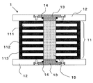
図1は、本発明の積層ゴム支承の一実施態様を示す縦断面図である。図1の積層ゴム支承1は、鋼板111とゴム層112とを交互に積層した積層体11、フランジプレート12、キャッププレート13、シール手段14、および弾塑性金属材料プラグ15を備える。
FIG. 1 is a longitudinal sectional view showing an embodiment of the laminated rubber bearing of the present invention. The laminated
本発明に用いられる積層体11は、鋼板111とゴム層112との積層構造を有する。
The
鋼板111としては、例えば、鉄系の鋼板、ステンレス系の鋼板などが挙げられる。これらの鋼板の中でも、腐食しにくいステンレス系の鋼板などが好ましい。
Examples of the
ゴム層112に用いられるゴム材料としては、例えば、天然ゴム、ブタジエンゴム、イソプレンゴム、ブチルゴム、クロロプレンゴム、ニトリルゴムなどが挙げられる。
Examples of the rubber material used for the
鋼板111とゴム層112との積層数は、積層ゴム支承として用いられ得る積層数であれば特に限定されず、好ましくは20層〜60層、より好ましくは30層〜50層である。さらに、積層体11の上面および底面は、いずれもゴム層112であることが好ましい。
The number of laminations of the
積層体11の側面は、通常、被覆ゴム113で被覆されている。被覆ゴム113に用いられるゴム材料としては、上記のゴム層112に用いられるゴム材料が挙げられる。
The side surface of the
積層体11の形状は、免震建物の構造、大きさ、設置される地形などによって適宜設定され得る。例えば、円柱状、角柱状などが挙げられる。角柱状としては、四角柱が挙げられる。積層体11の材料の性状に方向性がない点で、円柱状が好ましい。
The shape of the laminated
積層体11は、通常、後述する弾塑性金属材料プラグ15を挿入するための貫通孔を有する。貫通孔は、好ましくは、積層体11の中心付近で積層方向に上面から底面まで貫通するように形成される。貫通孔の断面形状としては円形、四角形などが挙げられ、通常、円形である。貫通孔の断面形状が円形の場合、直径は、好ましくは50cm〜500cm、より好ましくは90cm〜350cmである。さらに、貫通孔は、複数形成されてもよい。
The laminated
本発明に用いられるフランジプレート12は、一般的な積層ゴム支承に用いられるフランジプレートが用いられる。フランジプレート12は、積層体11の上下端面に接合され、通常、鉄製、ステンレス製など金属製の板である。フランジプレート12の形状、大きさ、厚みなどは、積層体11の形状、大きさなどに応じて適宜設定され得る。
As the
フランジプレート12には、通常、後述するキャッププレート13を嵌合するための孔が、積層体11の貫通孔に対応する場所に形成されている。
In the
本発明に用いられるキャッププレート13は、後述する弾塑性金属材料プラグ15の上下端面に接触させる。キャッププレート13の弾塑性金属材料プラグ15に接する接触端面は、好ましくは平均平面粗さ5μm〜25μmに形成され、弾塑性金属材料プラグ15に対するアンカー効果により地震エネルギーを入力し易い構造となっている。平均平面粗さが5μm未満の場合は、十分なアンカー効果が得られないおそれがある。また、平均平面粗さが25μmより大きい場合でも、アンカー効果が得られるが、25μmで十分なアンカー効果が得られるため、25μmを超える平均平面粗さは特に必要ない。キャッププレート13は、通常、鉄製、ステンレス製など金属製である。
The
キャッププレート13は、一般的に、弾塑性金属材料プラグ15の上下端面に接触させる際にフランジプレート12に嵌合される。しかし、上記のように、フランジプレート12とキャッププレート13との嵌合部分は、金属接触部となり微小な隙間が存在する。この隙間からの水、空気などの侵入、鉛、錫などを含む成分の漏洩を防ぐために、本発明においては、シール手段14が用いられる。シール手段14によって、フランジプレート12とキャッププレート13との隙間が封止される。
The
シール手段14としては、例えば、パッキン(Oリング、グランドパッキンなど)、樹脂系封止剤(エポキシ樹脂、シリコンシーラントなどの液状ガスケット)、ガスケットなどが挙げられる。これらの中でも、Oリング、グランドパッキン、樹脂系封止剤、ガスケットなどが好ましい。 Examples of the sealing means 14 include packing (O-ring, gland packing, etc.), resin sealant (liquid gasket such as epoxy resin, silicone sealant), gasket, and the like. Among these, an O-ring, a gland packing, a resin sealant, a gasket and the like are preferable.
Oリング、グランドパッキンなどのパッキンは、キャッププレート13の形状に応じて適宜設定され得、断面の形状は、例えば、円形状、角形状などである。Oリングを用いる場合、中空Oリングを用いてもよい。Oリングの材料としては、例えば、上記のゴム材料などが挙げられる。グランドパッキンの材料としては、上記のゴム材料、フッ素樹脂(ポリテトラフルオロエチレンなど)、黒鉛(膨張黒鉛など)、ポリアミド、ポリエチレンなどが挙げられる。また、繊維補強されたグランドパッキンなども用いられる。
A packing such as an O-ring or a gland packing can be appropriately set according to the shape of the
樹脂系封止剤としては、エポキシ樹脂、シリコンシーラントなどの液状ガスケットの硬化性樹脂が挙げられる。樹脂系封止剤は、硬化後に柔軟性を有するものでもよく、剛性を有するものでもよい。 Examples of the resin sealant include curable resins for liquid gaskets such as epoxy resins and silicone sealants. The resin sealant may have flexibility after curing or may have rigidity.
ガスケットとしては、上記ゴム材料でなるシート、黒鉛(膨張黒鉛など)でなるシート、フッ素樹脂(ポリテトラフルオロエチレンなど)でなるシート、ポリアミドでなるシートポリエチレンでなるシートなどが挙げられる。 Examples of the gasket include a sheet made of the above rubber material, a sheet made of graphite (such as expanded graphite), a sheet made of fluororesin (such as polytetrafluoroethylene), and a sheet made of polyethylene made of polyamide.
本発明に用いられる弾塑性金属材料プラグ15は、弾塑性金属製のため、振動に伴って変形し、変形した後に元の形状に戻りやすい性質を有する。このような弾塑性金属材料プラグ15を用いることによって、積層ゴム支承の振動減衰能力を補強することができる。
Since the elastoplastic
弾塑性金属材料プラグ15としては、鉛プラグおよび錫プラグが好ましく、純度が高い(99.9%以上)鉛および錫を用いたプラグがより好ましい。
As the elastoplastic
弾塑性金属材料プラグ15は、積層体11に設けられた貫通孔に密着するように挿入されるため、形状、大きさなどは、貫通孔に応じて適宜設定され得る。
Since the elastoplastic
図2〜9に、本発明の積層ゴム支承において、弾塑性金属材料プラグの端面を、キャッププレートおよびシール手段によって封止する種々の実施態様を示す。 2 to 9 show various embodiments in which the end face of the elastic-plastic metal material plug is sealed by the cap plate and the sealing means in the laminated rubber bearing of the present invention.
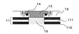
図2は、シール手段14がパッキンである実施態様を示す。 FIG. 2 shows an embodiment in which the sealing means 14 is a packing.
図2の積層ゴム支承は、弾塑性金属材料プラグ15が積層体11の貫通孔に密着するように挿入され、キャッププレート13が弾塑性金属材料プラグ15の上下端面に接触させる際にフランジプレート12に嵌合され、ボルトで固定されている。フランジプレート12とキャッププレート13との間に生じる隙間にパッキンが装着されている。パッキンはOリングである。パッキンを挿入する溝は、図2では、フランジプレート12に形成されているが、キャッププレート13に形成されていてもよい。
The laminated rubber support of FIG. 2 is inserted so that the elastic-plastic
このように、パッキンを装着することによって、フランジプレート12とキャッププレート13との隙間が封止され、水、空気などの侵入、鉛を含む成分の漏洩を防止することができる。Oリングの代わりにグランドパッキンを用いてもよい。
Thus, by mounting | wearing with packing, the clearance gap between the
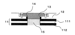
図3は、シール手段14として積層体11のゴム層112の一部を利用する実施態様を示す。
FIG. 3 shows an embodiment in which a part of the
図3の積層ゴム支承は、弾塑性金属材料プラグ15が積層体11の貫通孔に密着するように挿入され、キャッププレート13が弾塑性金属材料プラグ15の上下端面に接触させる際にフランジプレート12に嵌合され、ボルトで固定されている。この積層ゴム支承では、キャッププレート13と弾塑性金属材料プラグ15との接触面において、キャッププレート13の径を弾塑性金属材料プラグ15の径よりも大きくしている。そのため、キャッププレート13は、ゴム層112の一部とも接触し、キャッププレート13をボルトでフランジプレート12に固定する際に、キャッププレート13によってゴム層112の一部が圧迫されて隙間が封止される。
The laminated rubber bearing of FIG. 3 is inserted so that the elastoplastic
このように、積層体11のゴム層112の一部を利用することによって、フランジプレート12とキャッププレート13との隙間が封止され、水、空気などの侵入、鉛を含む成分の漏洩を防止することができる。
In this way, by utilizing a part of the
図4は、シール手段14が樹脂系封止剤である実施態様を示す。 FIG. 4 shows an embodiment in which the sealing means 14 is a resin sealant.
図4の積層ゴム支承は、弾塑性金属材料プラグ15が積層体11の貫通孔に密着するように挿入され、キャッププレート13が弾塑性金属材料プラグ15の上下端面に接触させる際にフランジプレート12に嵌合され、ボルトで固定されている。この積層ゴム支承では、ボルトで固定する代わりに、フランジプレート12とキャッププレート13との隙間に、樹脂系封止剤を注入し硬化させている。樹脂系封止剤はエポキシ樹脂である。
The laminated rubber bearing of FIG. 4 is inserted so that the elastoplastic
このように、接着剤ではなく樹脂系封止剤を用いることによって、フランジプレート12とキャッププレート13との隙間が封止され、水、空気などの侵入、鉛を含む成分の漏洩を防止することができる。エポキシ樹脂の代わりにシリコンシーラントを用いてもよい。
In this way, by using a resin-based sealant instead of an adhesive, the gap between the
図5は、シール手段14が樹脂系封止剤である実施態様を示す。 FIG. 5 shows an embodiment in which the sealing means 14 is a resin sealant.
図5の積層ゴム支承は、弾塑性金属材料プラグ15が積層体11の貫通孔に密着するように挿入され、キャッププレート13が弾塑性金属材料プラグ15の上下端面に接触させる際にフランジプレート12に嵌合され、ボルトで固定されている。フランジプレート12とキャッププレート13との間に生じる隙間に、樹脂系封止剤を注入し硬化させている。樹脂系封止剤はエポキシ樹脂である。
The laminated rubber bearing of FIG. 5 is inserted so that the elastic-plastic
このように、接着剤ではなく樹脂系封止剤を用いることによって、フランジプレート12とキャッププレート13との隙間が封止され、水、空気などの侵入、鉛を含む成分の漏洩を防止することができる。エポキシ樹脂の代わりにシリコンシーラントを用いてもよい。
In this way, by using a resin-based sealant instead of an adhesive, the gap between the
図6〜図9は、シール手段14がガスケットである実施態様を示す。 6 to 9 show an embodiment in which the sealing means 14 is a gasket.
図6および図7の積層ゴム支承は、弾塑性金属材料プラグ15が積層体11の貫通孔に密着するように挿入され、キャッププレート13が弾塑性金属材料プラグ15の上下端面に接触させる際にフランジプレート12に嵌合され、ボルトで固定されている。
6 and 7 is inserted when the elastoplastic
図6の積層ゴム支承では、フランジプレート12とキャッププレート13との水平方向の接触面の全面に、ガスケットが装着されている。一方、図7の積層ゴム支承では、フランジプレート12とキャッププレート13との水平方向の接触面の全面ではなく、ボルトの位置よりも内側の接触面にガスケットが装着されている。
In the laminated rubber bearing of FIG. 6, a gasket is mounted on the entire contact surface in the horizontal direction between the
図8の積層ゴム支承は、弾塑性金属材料プラグ15が積層体11の貫通孔に密着するように挿入され、キャッププレート13が弾塑性金属材料プラグ15の上下端面に接触させる際にフランジプレート12に嵌合され、ボルトで固定されている。この積層ゴム支承では、キャッププレート13と弾塑性金属材料プラグ15との接触面にガスケットが装着されている。
The laminated rubber bearing of FIG. 8 is inserted so that the elastic-plastic
図9の積層ゴム支承は、弾塑性金属材料プラグ15が積層体11の貫通孔に密着するように挿入され、キャッププレート13が弾塑性金属材料プラグ15の上下端面に接触させる際にフランジプレート12に嵌合され、ボルトで固定されている。この積層ゴム支承では、フランジプレート12とキャッププレート13との間にガスケットが装着されている。
The laminated rubber support of FIG. 9 is inserted so that the elastoplastic
このように、ガスケットを装着することによって、フランジプレート12とキャッププレート13との隙間が封止され、水、空気などの侵入、鉛を含む成分の漏洩を防止することができる。
As described above, by mounting the gasket, the gap between the
以上、本発明を詳細に説明したが、上記実施態様は例示にすぎず、本発明はこれらの実施態様に限定されるものではない。 As mentioned above, although this invention was demonstrated in detail, the said embodiment is only an illustration and this invention is not limited to these embodiments.
本発明によれば、優れた振動減衰能力を有し、さらにプラグとして用いられる鉛、錫などの成分が大気中、土壌中などに漏洩せず環境汚染を防止し得る積層ゴム支承を提供することができる。したがって、本発明の積層ゴム支承は、集合住宅、ビル(商業ビルなど)、官庁建物、病院、工場、戸建て住宅など免震建物の支承装置として用いられる。 According to the present invention, it is possible to provide a laminated rubber bearing that has excellent vibration damping capability and that can prevent environmental pollution without leaking components such as lead and tin used as a plug into the atmosphere and soil. Can do. Therefore, the laminated rubber bearing of the present invention is used as a bearing device for seismic isolation buildings such as apartment houses, buildings (commercial buildings, etc.), government office buildings, hospitals, factories, and detached houses.
1 積層ゴム支承
11 積層体
111 鋼板
112 ゴム層
113 被覆ゴム
12 フランジプレート
13 キャッププレート
14 シール手段
15 弾塑性金属材料プラグ
DESCRIPTION OF
Claims (3)
該積層体が、積層方向に貫通する貫通孔を有し、該貫通孔に密着するように該弾塑性金属材料プラグが挿入され、
挿入された弾塑性金属材料プラグの上下端面と積層体の上下端面が面一であり、
該弾塑性金属材料プラグの上下端面が、それぞれ該キャッププレートに接触し、
キャッププレートの弾塑性金属材料プラグに接する接触端面が平均平面粗さ5μm以上であり、
該積層体の上下端面が、それぞれ該フランジプレートに接合され、
該キャッププレートが、該フランジプレートに嵌合され、そして
該フランジプレートと該キャッププレートとの隙間が、該シール手段によって封止されている、
積層ゴム支承。 A laminated rubber bearing comprising a laminate in which steel plates and rubber layers are alternately laminated, a flange plate, a cap plate, a sealing means, and an elastic-plastic metal material plug,
The laminated body has a through-hole penetrating in the laminating direction, and the elastic-plastic metal material plug is inserted so as to be in close contact with the through-hole,
The upper and lower end surfaces of the inserted elastic-plastic metal material plug and the upper and lower end surfaces of the laminate are flush with each other,
The upper and lower end surfaces of the elastoplastic metal plug are in contact with the cap plate, respectively.
The contact end face of the cap plate contacting the elastic-plastic metal material plug has an average plane roughness of 5 μm or more,
Upper and lower end surfaces of the laminate are respectively joined to the flange plate,
The cap plate is fitted to the flange plate, and a gap between the flange plate and the cap plate is sealed by the sealing means;
Laminated rubber bearing.
Priority Applications (1)
| Application Number | Priority Date | Filing Date | Title |
|---|---|---|---|
| JP2010107994A JP5497528B2 (en) | 2010-05-10 | 2010-05-10 | Laminated rubber support |
Applications Claiming Priority (1)
| Application Number | Priority Date | Filing Date | Title |
|---|---|---|---|
| JP2010107994A JP5497528B2 (en) | 2010-05-10 | 2010-05-10 | Laminated rubber support |
Publications (2)
| Publication Number | Publication Date |
|---|---|
| JP2011236957A JP2011236957A (en) | 2011-11-24 |
| JP5497528B2 true JP5497528B2 (en) | 2014-05-21 |
Family
ID=45325166
Family Applications (1)
| Application Number | Title | Priority Date | Filing Date |
|---|---|---|---|
| JP2010107994A Active JP5497528B2 (en) | 2010-05-10 | 2010-05-10 | Laminated rubber support |
Country Status (1)
| Country | Link |
|---|---|
| JP (1) | JP5497528B2 (en) |
Cited By (1)
| Publication number | Priority date | Publication date | Assignee | Title |
|---|---|---|---|---|
| KR102501532B1 (en) * | 2022-10-17 | 2023-02-21 | (주)솔방이엔지 | Earthquake reduction device for water tank |
Families Citing this family (2)
| Publication number | Priority date | Publication date | Assignee | Title |
|---|---|---|---|---|
| JP5845130B2 (en) * | 2012-04-12 | 2016-01-20 | 昭和電線デバイステクノロジー株式会社 | Laminated rubber bearing |
| CN107021251B (en) | 2016-01-29 | 2018-10-16 | 住友化学株式会社 | The assembly and its manufacturing method that coiling body to being wound with film is assembled |
Family Cites Families (1)
| Publication number | Priority date | Publication date | Assignee | Title |
|---|---|---|---|---|
| JP2005233205A (en) * | 2004-02-17 | 2005-09-02 | Sachiyo Kikaku:Kk | Vibration-isolation support system |
-
2010
- 2010-05-10 JP JP2010107994A patent/JP5497528B2/en active Active
Cited By (1)
| Publication number | Priority date | Publication date | Assignee | Title |
|---|---|---|---|---|
| KR102501532B1 (en) * | 2022-10-17 | 2023-02-21 | (주)솔방이엔지 | Earthquake reduction device for water tank |
Also Published As
| Publication number | Publication date |
|---|---|
| JP2011236957A (en) | 2011-11-24 |
Similar Documents
| Publication | Publication Date | Title |
|---|---|---|
| US9892945B2 (en) | Composite seal | |
| JP5497528B2 (en) | Laminated rubber support | |
| KR101599334B1 (en) | Supporting Structure for Sound proof tunnel | |
| JP2012072906A (en) | System for dynamically sealing conduit sleeve through which pipe or cable extends | |
| JP2009144735A5 (en) | ||
| JP5649618B2 (en) | Seal structure and method for forming seal structure | |
| JP6340292B2 (en) | Seal structure and building | |
| JP2009002407A (en) | Penetration section sealing member and penetration section sealing method | |
| EA034713B1 (en) | Encapsulation assembly and forming method thereof, and vehicle window | |
| JP2015094093A (en) | Foundation combining use of support member for roof installation facility | |
| CN103746081A (en) | Battery pack sealing piece for pure electric vehicle | |
| JP2014040860A (en) | Seal structure and construction method for the same | |
| JP2014025264A (en) | Seal structure, and construction method for the same | |
| JP6653615B2 (en) | Sliding seismic isolation device | |
| JP2013160261A (en) | End structure of pipe penetration section | |
| JP6378663B2 (en) | Seam structure of the manhole wall | |
| JP4648721B2 (en) | Base isolation structure for buildings | |
| JP2007214105A (en) | Cell seal for fuel cell | |
| WO2024029056A1 (en) | Magnet-type water stop device | |
| JP2014141794A (en) | Reinforcement structure for existing building | |
| JP6650811B2 (en) | Seal structure | |
| CN219317608U (en) | Sealing structure for fire grate shaft and fire grate shaft using same | |
| CN211649047U (en) | Dustproof gasket subassembly | |
| JP4286318B1 (en) | Bridge bearing device | |
| JP6843705B2 (en) | Gasket and engine |
Legal Events
| Date | Code | Title | Description |
|---|---|---|---|
| A621 | Written request for application examination |
Free format text: JAPANESE INTERMEDIATE CODE: A621 Effective date: 20121106 |
|
| A977 | Report on retrieval |
Free format text: JAPANESE INTERMEDIATE CODE: A971007 Effective date: 20130828 |
|
| A131 | Notification of reasons for refusal |
Free format text: JAPANESE INTERMEDIATE CODE: A131 Effective date: 20130910 |
|
| A521 | Written amendment |
Free format text: JAPANESE INTERMEDIATE CODE: A523 Effective date: 20131021 |
|
| TRDD | Decision of grant or rejection written | ||
| A01 | Written decision to grant a patent or to grant a registration (utility model) |
Free format text: JAPANESE INTERMEDIATE CODE: A01 Effective date: 20140304 |
|
| A61 | First payment of annual fees (during grant procedure) |
Free format text: JAPANESE INTERMEDIATE CODE: A61 Effective date: 20140306 |
|
| R150 | Certificate of patent or registration of utility model |
Ref document number: 5497528 Country of ref document: JP Free format text: JAPANESE INTERMEDIATE CODE: R150 |