JP5484213B2 - Recording apparatus and image processing method - Google Patents
Recording apparatus and image processing method Download PDFInfo
- Publication number
- JP5484213B2 JP5484213B2 JP2010142993A JP2010142993A JP5484213B2 JP 5484213 B2 JP5484213 B2 JP 5484213B2 JP 2010142993 A JP2010142993 A JP 2010142993A JP 2010142993 A JP2010142993 A JP 2010142993A JP 5484213 B2 JP5484213 B2 JP 5484213B2
- Authority
- JP
- Japan
- Prior art keywords
- recording
- nozzle group
- nozzle
- nozzle rows
- image
- Prior art date
- Legal status (The legal status is an assumption and is not a legal conclusion. Google has not performed a legal analysis and makes no representation as to the accuracy of the status listed.)
- Active
Links
Images


Classifications
-
- B—PERFORMING OPERATIONS; TRANSPORTING
- B41—PRINTING; LINING MACHINES; TYPEWRITERS; STAMPS
- B41J—TYPEWRITERS; SELECTIVE PRINTING MECHANISMS, i.e. MECHANISMS PRINTING OTHERWISE THAN FROM A FORME; CORRECTION OF TYPOGRAPHICAL ERRORS
- B41J29/00—Details of, or accessories for, typewriters or selective printing mechanisms not otherwise provided for
- B41J29/38—Drives, motors, controls or automatic cut-off devices for the entire printing mechanism
- B41J29/393—Devices for controlling or analysing the entire machine ; Controlling or analysing mechanical parameters involving printing of test patterns
Landscapes
- Ink Jet (AREA)
- Particle Formation And Scattering Control In Inkjet Printers (AREA)
Description
本発明は、記録装置および画像処理方法に関し、特に、濃度ムラを補正する記録装置および画像処理方法に関するものである。 The present invention relates to a recording apparatus and an image processing method, and more particularly to a recording apparatus and an image processing method for correcting density unevenness.
インクジェット記録装置は、同色のインクを吐出するための、複数の記録ヘッドもしくは複数のノズル列を備えたものが知られている。複数の記録ヘッドや複数のノズル列を備えることにより、記録速度の向上を図ることができる。しかし、このような複数の記録ヘッドや複数の吐出口列を備えた記録装置では、記録画像において濃度ムラあるいは色ムラを生じることがある。これは、記録ヘッドごとあるいはノズル列ごとに吐出特性の違いが存在しあるいは生じることが1つの原因である。このような記録ヘッドごとあるいはノズル列ごとに吐出特性が異なる要因として、インクを吐出させるための発熱ヒータの発熱量のばらつきやインクを吐出するノズル(吐出口)の口径のばらつきなどが挙げられる。また、経年変化による発熱ヒータの発熱量の変動や、使用環境の違いによるインクの粘性の変動によっても、吐出特性に差が生じることがある。 An ink jet recording apparatus is known that includes a plurality of recording heads or a plurality of nozzle rows for ejecting ink of the same color. By providing a plurality of recording heads and a plurality of nozzle rows, the recording speed can be improved. However, in such a recording apparatus including a plurality of recording heads and a plurality of ejection port arrays, density unevenness or color unevenness may occur in a recorded image. One reason for this is that there exists or occurs a difference in ejection characteristics for each print head or nozzle row. Factors that cause different ejection characteristics for each recording head or nozzle array include variations in the amount of heat generated by the heater for ejecting ink and variations in the diameter of nozzles (ejection ports) that eject ink. In addition, there may be a difference in ejection characteristics due to fluctuations in the amount of heat generated by the heating heater due to secular change, and fluctuations in ink viscosity due to differences in use environment.
このような吐出特性の違いに起因した濃度ムラなどを抑制するために、キャリブレーション技術が知られている。このキャリブレーションは、例えば、記録ヘッドの吐出特性を補正するために画像処理の一環として行われるγ補正処理で用いるテーブルを変更することによって行われる。具体的には、記録媒体にパッチを記録し、そのパッチの記録結果からそのときの記録ヘッドもしくはノズル列ごとの吐出特性を検出し、γ補正処理で用いるテーブルを適切なものに設定し直すことにより行なわれる。記録したパッチに基づいて吐出特性を検出する方法としては、記録したパッチを目視によって検出(検査)する方法や、スキャナなどの入力機器を用いて検出する方法がある。 In order to suppress density unevenness caused by such a difference in ejection characteristics, a calibration technique is known. This calibration is performed, for example, by changing a table used in γ correction processing performed as part of image processing to correct the ejection characteristics of the recording head. Specifically, the patch is recorded on the recording medium, the ejection characteristic for each recording head or nozzle array is detected from the recording result of the patch, and the table used in the γ correction processing is reset to an appropriate one. It is done by. As a method for detecting the ejection characteristics based on the recorded patch, there are a method for visually detecting (inspecting) the recorded patch, and a method for detecting it using an input device such as a scanner.
例えば、特許文献1には、記録装置におけるキャリッジにパッチを読み取るためのスキャナもしくは光センサを設け、このスキャナなどによって記録したパッチの濃度測定を行うことが記載されている。そして、測定結果に基づいて濃度ムラあるいは色ムラの補正(キャリブレーション)を自動で行う方法が記載されている。この方法では、各インク色の記録ヘッドについてそれぞれキャリブレーションを行い、対応する各インク色の階調ごとの濃度補正値を求めている。このように、従来知られるキャリブレーションの多くは、上記特許文献1に記載されるようにインク色ごとの1つの記録ヘッドに関して行うものである。
For example,
これに対し、前述した記録装置のように、同じインク色について複数の記録ヘッドもしくは複数のノズル列を備える構成では、キャリブレーションは代表的な記録ヘッドもしくはノズル列に関して行う。そして、そこで求めた濃度補正値を他の記録ヘッドもしくはノズル列にも適用することが行われている。 On the other hand, in a configuration including a plurality of recording heads or a plurality of nozzle rows for the same ink color as in the recording apparatus described above, the calibration is performed with respect to a typical recording head or nozzle row. The density correction value obtained there is also applied to other recording heads or nozzle rows.
しかしながら、記録ヘッドごとあるいはノズル列ごとに吐出特性の違いが存在する場合に、代表的な記ノズル列などについてのみキャリブレーションを行い、その結果求められる濃度補正値を他のノズル列などに適用する構成では、適切な濃度補正ができない。これに対して、記録ヘッドごとあるいはノズル列ごとに濃度補正値を求めたとしても、これら複数の記録ヘッドもしくはノズル列の使用比率が記録領域ごとに異なる場合には、不都合を生じる。すなわち、ノズル列ごとの異なる濃度補正量が記録領域ごとに使用比率に応じて現れることになり、記録領域間で濃度ムラを生じるという新たな問題を派生する。 However, when there is a difference in ejection characteristics for each print head or nozzle row, calibration is performed only for a typical nozzle row and the density correction value obtained as a result is applied to other nozzle rows and the like. With the configuration, appropriate density correction cannot be performed. On the other hand, even if the density correction value is obtained for each recording head or nozzle row, inconvenience occurs when the usage ratios of the plurality of recording heads or nozzle rows are different for each recording region. That is, a different density correction amount for each nozzle row appears in accordance with the use ratio for each recording area, and this leads to a new problem that density unevenness occurs between the recording areas.
例えば、複数のノズル列がノズルの配列方向と交差する方向にオーバーラップするように配列された記録ヘッドを走査させて記録を行う記録装置では、ラスタごとに記録に使用される複数ノズル列の使用比率が異なる場合がある。この場合には、カラム方向に濃淡の変化が現れる濃度ムラが発生することがある。 For example, in a recording apparatus that performs recording by scanning a recording head arranged so that a plurality of nozzle rows overlap in a direction intersecting the nozzle arrangement direction, use of the plurality of nozzle rows used for recording for each raster The ratio may be different. In this case, density unevenness in which a change in shading appears in the column direction may occur.
また、例えば、記録媒体に対する記録ヘッドの相対的な走査方向にノズル列が複数配列された、いわゆるフルライン方式の記録装置でも、カラムごとに記録に使用される複数ノズル列の使用比率が異なると、ラスタ方向に濃淡の濃度ムラが発生することがある。 Further, for example, even in a so-called full-line recording apparatus in which a plurality of nozzle arrays are arranged in the scanning direction relative to the recording medium, the use ratio of the plurality of nozzle arrays used for recording differs from column to column. In some cases, uneven density in the raster direction may occur.
本発明の目的は、記録に使用する複数ノズル列の使用比率が異なる場合であっても適切な濃度ムラ補正を行うことができる記録装置および画像処理方法を提供することである。 An object of the present invention is to provide a recording apparatus and an image processing method capable of performing appropriate density unevenness correction even when the usage ratios of a plurality of nozzle arrays used for recording are different.
この目的を達成するために本発明は、同色のインクを付与する複数のノズル列を備えた記録ヘッドと、記録媒体の単位領域と、の少なくとも1回の相対走査の間に、前記記録ヘッドの前記複数のノズル列によって前記単位領域にインクを付与することにより前記単位領域に画像を記録するための処理を行う画像処理装置であって、前記単位領域に対応する多値画像データを取得する取得手段と、前記単位領域の記録における前記複数のノズル列それぞれの寄与率を設定する設定手段と、前記複数のノズル列間の吐出特性による濃度差を低減するために、前記複数のノズル列にそれぞれ対応する複数の濃度補正データと前記寄与率とに基づいて、前記多値画像データを補正する補正手段と、を具えたことを特徴とする。 In order to achieve this object, the present invention relates to a recording head including at least one relative scan between a recording head having a plurality of nozzle arrays for applying ink of the same color and a unit area of the recording medium. An image processing apparatus that performs a process for recording an image in the unit area by applying ink to the unit area by the plurality of nozzle rows, and acquires multi-value image data corresponding to the unit area Means for setting the contribution ratio of each of the plurality of nozzle rows in the recording of the unit area, and each of the plurality of nozzle rows in order to reduce a density difference due to ejection characteristics between the plurality of nozzle rows. And a correction unit that corrects the multi-valued image data based on a plurality of corresponding density correction data and the contribution rate.
以上の構成によれば、記録に使用するノズル列の使用比率に応じてそれぞれのノズル列の濃度補正を行うことができ、複数ノズル列の吐出特性が異なることによって生じる濃度ムラもしくは色ムラを低減することができる。 According to the above configuration, it is possible to perform density correction of each nozzle array in accordance with the usage ratio of the nozzle arrays used for recording, and reduce density unevenness or color unevenness caused by different ejection characteristics of the plurality of nozzle arrays. can do.
(第1の実施形態)
以下に図面を参照して本発明における実施形態を詳細に説明する。
(First embodiment)
Embodiments of the present invention will be described below in detail with reference to the drawings.
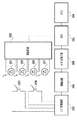
図1は、本発明の第1の実施形態に係る記録システムの構成を示すブロック図である。ホスト装置100は、パーソナルコンピュータやデジタルカメラなど、記録装置200に接続される情報処理装置である。このホスト装置100は、CPU10と、メモリ11と、記憶部13と、キーボードやマウス等の入力部12と、記録装置200との間の通信のためのインターフェース14とを備えている。CPU10は、メモリ11に格納されたプログラムに従い、種々の処理を実行するものである。これらのプログラムは、記憶部13が記憶するためにCD−ROMなどの外部装置から供給されたり、予め記憶部13に記憶されている。
FIG. 1 is a block diagram showing a configuration of a recording system according to the first embodiment of the present invention. The
ホスト装置100はインターフェース14を介して記録装置200と接続されており、後述する画像処理工程におけるR′、G′、B′で表される記録データと、その後の画像処理用のテーブルを記録装置200に送信する。記録装置200は、送信された画像処理情報を基に、特に後述の色処理、2値化処理等の画像処理や、本実施形態に関する記録特性の補正処理を実行する。また、画像処理を施した記録データの記録を行うことができる。
The
図2は、記録装置200の機械的構成を示す概略斜視図である。記録用紙、プラスチックシート等の記録媒体1は、不図示のカセット等に複数枚が積層されることにより、記録時には不図示の給紙ローラによって1枚ずつ分離されて供給される。給紙された記録媒体は、一定間隔を隔てて配置される第1搬送ローラ3および第2搬送ローラ4により、記録ヘッドの走査に応じたタイミングで矢印A方向(以下、搬送方向、副走査方向とも称する。)に所定量ずつ搬送される。第1搬送ローラ3は、ステッピングモータ(不図示)によって駆動される駆動ローラと駆動ローラの回転にともなって回転する従動ローラの1対のローラからなる。同様に、第2搬送ローラも1対のローラからなる。なお、記録装置200は、カセットに積層された所定の大きさにカットされた記録媒体以外に、ロール状の記録媒体に記録することも可能である。
FIG. 2 is a schematic perspective view showing the mechanical configuration of the
キャリッジ6に搭載された記録ヘッド5は、YMCK各色のインクを吐出して記録を行うインクジェット方式の記録ヘッドである。本実施形態の記録ヘッド5は、分離した複数の記録ヘッドが集合して形成されている。集合体としての記録ヘッド5を形成するそれぞれの記録ヘッドはノズル列を有している。記録ヘッド5には、不図示のインクカートリッジからインクが供給される。そして、記録ヘッド5は、吐出信号に応じて駆動されることによりノズル列を形成するそれぞれのノズル(吐出口)から各色のインクを吐出する。すなわち、インクを吐出するそれぞれのノズル内には、電気熱変換素子(ヒータ)が設けられており、吐出信号に応じた電気熱変換素子の駆動により発生する熱エネルギを利用してインクに気泡を発生させ、この気泡の圧力によってインクを吐出する。
The
キャリッジ6にはベルト7およびプーリ8a、8bを介してキャリッジモータ2の駆動力が伝達される。これにより、キャリッジ6はガイドシャフト9に沿って矢印B方向(以下、主走査方向とも称する。)に往復運動し、これにより、記録ヘッド5の走査を行うことができる。また、キャリッジ6の側面には後述する多目的センサが搭載されている。多目的センサは、記録媒体に吐出したインクの濃度検知や、記録媒体の幅検知、記録ヘッドから記録媒体までの距離検知などに使用される。
The driving force of the
以上の構成において、記録ヘッド5は、主走査方向に往復走査しながら吐出信号に応じて記録ヘッドからインクを吐出することで、記録媒体1上にインクのドットを形成して記録を行う(以下、記録走査とも称する。)ことができる。記録ヘッド5は、必要に応じてホームポジションに移動し、ホームポジション位置に設けられた吐出回復装置による回復動作を行うことにより、吐出口の目詰まり等による吐出不良の状態から回復する。記録ヘッド5による記録走査の後、搬送ローラ対3、4が駆動されて記録媒体1は矢印A方向に所定量搬送される。この記録ヘッド5の記録走査と記録媒体の搬送動作とを交互に繰り返すことにより、記録媒体1に画像等の記録を行うことができる。
In the above configuration, the
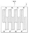
図3は、記録ヘッド5をインク吐出口(ノズル)を配設した面から見た正面図である。本実施形態の記録装置は、同一の色のインクを吐出する複数のノズル列を備えた記録ヘッドを有するものである。図3において、記録ヘッド5には記録媒体の排紙方向に向かって上部には4個のノズル列5a、5b、5cおよび5d(以下、単にノズル群または上ノズル群とも称する。)が配置されている。また、記録媒体の排紙方向に向かって下部には4個のノズル列5e、5f、5gおよび5h(以下、単にノズル群または下ノズル群とも称する。)が配置されている。ノズル群5a、5eからはシアン(C)インク、ノズル群5b、5fからはマゼンタ(M)インク、ノズル群5c、5gからはイエロー(Y)インク、ノズル群5d、5hからはブラック(K)インクがそれぞれ吐出される。なお、インク色の種類はこれらの種類のみに限られるものではない。また、集合体としての記録ヘッド5を形成する記録ヘッドのそれぞれに形成されるノズル群は、上ノズル群および下ノズル群の2群に限定されず、3群以上配列されたものであっても良い。
FIG. 3 is a front view of the
このように、本実施形態では、記録ヘッド5は、複数の色のインクに対応した複数の記録ヘッドとして、各インク色のノズル列を走査方向に配列した形態のものである。そして、本実施形態では、複数のノズル列のうち、図中、上下方向に配列するそれぞれ、上ノズル群5aと下ノズル群5e、上ノズル群5bと下ノズル群5f、上ノズル群5cと下ノズル群5g、上ノズル群5dと下ノズル群5hは、それぞれ同じ色のインクを吐出するノズル群である。さらに、上ノズル群5aと下ノズル群5e、上ノズル群5bと下ノズル群5f、上ノズル群5cと下ノズル群5g、上ノズル群5dと下ノズル群5hは、走査方向に重複した部分(オーバーラップ部)を有するように配設されている。すなわち、複数のノズル列は、ノズルの配列方向と交差する方向に重複する重複部を有するように上記配列方向にずれて配列されている。
As described above, in the present embodiment, the
図4は、記録装置200の制御構成を示すブロック図である。制御部20は、マイクロプロセッサ等のCPU20a、ROM20cおよびRAM20b等をメモリとして備えている。ROM20cは、CPU20aの制御プログラムや記録動作に必要なパラメータなどの各種データを格納している。RAM20bは、CPU20aのワークエリアとして使用されると共に、ホスト装置100から受信した画像データや生成した記録データなどの各種データの一時保管等を行う。また、ROM20cには図7を用いて後に説明するテーブルとしてのLUT(ルックアップテーブル)が、RAM20bにはパッチを記録するためのパッチデータがそれぞれ格納されている。なお、LUTはRAM20bに格納してもよく、パッチデータはROM20cに格納してもよい。
FIG. 4 is a block diagram illustrating a control configuration of the
制御部20は、インターフェース21を介してホスト装置100との間で画像データ等の記録に用いられるデータ、パラメータを入出力する処理や、操作パネル22から各種情報(例えば文字ピッチ、文字種類等)を入力する処理を行う。また、制御部20は、インターフェース21を介して各モータ23〜26を駆動させるためのON、OFF信号を出力する。さらに、吐出信号等をドライバ28に出力して記録ヘッドにおけるインク吐出のための駆動を制御する。
The
また、この制御系は、インターフェース21、操作パネル22、多目的センサ102、ドライバ27および28を有している。ドライバ27は、CPU20aからの指示に従ってキャリッジ駆動用のモータ23、給紙ローラ駆動用のモータ24、第1搬送ローラ対駆動用のモータ25、第2搬送ローラ対駆動用のモータ26を駆動する。ドライバ28は記録ヘッド5それぞれを駆動する。
The control system includes an
図5(a)および(b)は、多目的センサ102を示す構成図である。図5(a)は多目的センサ102の平面図を、図5(b)は断面図を、それぞれ示している。
FIGS. 5A and 5B are configuration diagrams showing the
多目的センサ102は、測定領域が記録ヘッド5の記録面に対し下流側に位置し、また、多目的センサ102の下面は、記録ヘッド5の下面と同位置もしくはそれよりも高くなるように配置されている。多目的センサ102は、光学素子として2つのフォトトランジスタ203および204と、3つの可視LED205、206および207と、1つの赤外LED201とを備えており、それぞれの素子の駆動は不図示の外部回路によって行われる。これらの素子は全て直径が最大部分で約4mmの砲弾型素子(一般的なφ3.0〜3.1mmサイズの量産型タイプ)である。
The
なお、本実施形態では、発光素子から測定面に対して照射された照射光の照射範囲の中心点と発光素子の中心とを結ぶ直線を、発光素子の光軸、または照射軸と称する。この照射軸は、照射光の光束の中心でもある。 In this embodiment, a straight line connecting the center point of the irradiation range of the irradiation light irradiated from the light emitting element to the measurement surface and the center of the light emitting element is referred to as an optical axis of the light emitting element or an irradiation axis. This irradiation axis is also the center of the luminous flux of the irradiation light.
赤外LED201は、XY平面と平行な記録媒体の表面(測定面)に対して45度の照射角を持つ。そして、その照射光中心である照射軸は、測定面の法線(Z軸)と平行なセンサ中心軸202と所定の位置で交差するように配置されている。この交差する位置(交点)のZ軸上における位置を基準位置とし、センサから基準位置までの距離を基準距離とする。赤外LED201の照射光は開口部によって照射光の幅が調整され、基準位置にある測定面に直径約4〜5mmの照射面(照射領域)を形成するように最適化されている。
The
2つのフォトトランジスタ203および204は可視光から赤外光までの波長の光に対して感度を持っている。測定面が基準位置にあるとき、フォトトランジスタ203および204は、その受光軸が赤外LED201の反射軸と平行となるように設置されている。すなわち、反射軸に対しフォトトランジスタ203の受光軸はX方向に+2mm、Z方向に+2mm移動した位置となるように配置されている。また、フォトトランジスタ204の受光軸はX方向に−2mm、Z方向に−2mm移動した位置となるように配置されている。測定面が基準位置にあるとき、測定面と赤外LED201と可視LED205の照射軸の交点が一致し、また、この位置における2つのフォトトランジスタ203および204の受光領域がこの交点を挟むように形成される。2つの素子の間には厚さ約1mmのスペーサーがはさまれており、互いに受光した光が回り込まないような構造となっている。フォトトランジスタ側にも入光範囲を制限するために開口部が設けられており、その大きさは基準位置にある測定面の直径3〜4mmの範囲の反射光のみを受光可能となるように最適化される。なお、本実施形態においては、測定面(測定対象表面)において、受光素子が受光可能である領域(範囲)の中心点と受光素子の中心とを結ぶ線を、受光素子の光軸、または受光軸と称する。この受光軸は、測定面で反射し、受光素子に受光される反射光の光束の中心でもある。
The two
図5(a)および(b)において、LED205は、緑色の発光波長(約510〜530nm)を持つ単色可視LEDであり、センサ中心軸202と一致するように設置される。また、LED206は、青色の発光波長(約460〜480nm)を持つ単色可視LEDであり、図5(a)に示すように可視LED205に対しX方向に+2mm、Y方向に−2mm移動した位置に配置されている。そして、測定面が基準位置にあるとき、可視LED206の照射軸と測定面との交点位置においてフォトトランジスタ203の受光軸と交差するように配置される。さらに、LED207、は赤色の発光波長(約620〜640nm)を持つ単色可視LEDであって、図5(a)に示すように可視LED205に対しX方向に−2mm、Y方向に+2mm離れた位置にある。そして、測定面が基準位置にあるとき、可視LED207の照射軸と測定面との交点位置においてフォトトランジスタ204の受光軸と交差するように配置される。
5A and 5B, an
図6は、本実施形態に係る多目的センサ102のそれぞれのセンサの入出力信号を処理する制御回路の概略図を示している。CPU301は、赤外LED201および可視LED205〜207のオン/オフの制御信号の出力やフォトトランジスタ203、204の受光量に応じて得られる出力信号の演算などを行う。駆動回路302は、CPU301から送られるオン信号を受けてそれぞれの発光素子へ定電流を供給し発光させたり、受光素子の受光量が所定量となるようにそれぞれの発光素子の発光量を調整したりする。I/V変換回路303は、フォトトランジスタ203、204から電流値として送られてきた出力信号を電圧値に変換する。増幅回路304は、微小信号である電圧値に変換後の出力信号を、A/D変換において最適なレベルまで増幅する働きをする。A/D変換回路305は、増幅回路304で増幅された出力信号を10bitディジタル値に変換してCPU301に入力する。メモリ(不揮発性メモリなど)306は、CPU301の演算結果から所望の測定値を導き出すための参照テーブルの記録や出力値の一時的な記憶に用いられる。なお、このCPU301やメモリ306は、記録装置のCPU20aやRAM20bを用いてもよい。
FIG. 6 is a schematic diagram of a control circuit that processes input / output signals of each sensor of the
次に、記録装置200で用いる記録データを、ホスト装置100と記録装置200で生成するための画像処理方法について説明する。
Next, an image processing method for generating recording data used in the
図7は、本実施形態の画像処理の構成を示すブロック図である。本実施形態の画像処理では、レッド(R)、グリーン(G)、ブルー(B)各色8ビット(それぞれ256階調)の画像データ(輝度データ)が入力される。最終的にノズル群5a〜5hにより記録される各ノズルについて1ビットのビットイメージデータ(記録データ)として出力する処理を行う。なお、色の種類や、色の階調はこの値に限るものではない。
FIG. 7 is a block diagram illustrating a configuration of image processing according to the present embodiment. In the image processing of the present embodiment, image data (luminance data) of 8 bits (256 gradations) for each color of red (R), green (G), and blue (B) is input. Finally, a process of outputting 1-bit bit image data (recording data) for each nozzle recorded by the
まず、ホスト装置100において、多次元のLUT401を用いてR、G、B多値の輝度信号で表現される画像データが、R′、G′、B′多値のデータに変換される。この色空間変換前処理(以下、前段色処理とも称する。)は、記録対象におけるR、G、Bの画像データが表わす入力画像の色空間と、記録装置200で再現可能な色空間との間の差を補正するために行なわれる。
First, in the
前段色処理を施されたR′、G′、B′各色のデータは、記録装置200に送信される。記録装置200は、まず、多次元LUT402を用いてホスト装置より受信した、前段色処理が施されたR′、G′、B′各色のデータをC、M、Y、Kの多値のデータに変換する。この色変換処理(以下、後段処理とも称する。)は、輝度信号で表現される入力系のRGB系画像データを、濃度信号で表現するための出力系のCMYK系の画像データに変換する処理である。
Data of each color R ′, G ′, and B ′ subjected to the preceding color processing is transmitted to the
次に、後段色処理が施されたC、M、Y、Kの多値のデータは、それぞれの色の1次元LUT403により出力γ補正が行なわれる。通常、記録媒体の単位面積当たりに記録されるドットの数と、記録された画像を測定して得られる反射濃度などの記録特性は、線形関係にならない。そのため、C、M、Y、K各10ビットの入力階調レベルとそれによって記録される画像の濃度レベルが線形関係となるように、C、M、Y、Kの多値の入力階調レベルを補正する出力γ補正処理が行なわれる。
Next, C, M, Y, and K multi-valued data that have undergone post-stage color processing are subjected to output γ correction by the one-
前述したように、出力γ補正テーブル(1次元LUT403)は、標準的な記録特性を示す記録ヘッド用に作成されたものが用いられることが多い。しかし、前述したように、記録ヘッドもしくはノズル群には吐出特性に関して個体差がある。このため、標準的な吐出特性を示す記録ヘッドもしくはノズル群の記録特性を補正する出力γ補正テーブルだけでは、全ての記録ヘッドもしくはノズル群に対して適切な濃度補正をすることができない。 As described above, the output γ correction table (one-dimensional LUT 403) is often used for a print head showing standard print characteristics. However, as described above, there are individual differences in the ejection characteristics between the print heads or nozzle groups. For this reason, it is not possible to perform appropriate density correction for all the recording heads or nozzle groups with only the output γ correction table for correcting the recording characteristics of the recording heads or nozzle groups exhibiting standard ejection characteristics.
このため、本実施形態では、出力γ補正が施されたC、M、Y、Kの多値データについて、色ずれ補正処理を行う。この色ずれ補正処理は、各色について、上ノズル群の色ずれ補正用1次元LUT404、および下ノズル群の色ずれ補正用1次元LUT405によって行われる。
For this reason, in this embodiment, color misregistration correction processing is performed on C, M, Y, and K multivalued data that has undergone output γ correction. This color misregistration correction process is performed for each color by the one-
ここで、それぞれの色の色ずれ補正用1次元LUTついて述べる。色ずれ補正出力γ補正は、キャリブレーション工程において取得される、ノズル群毎の濃度値情報より設定される。 Here, a one-dimensional LUT for color misregistration correction of each color will be described. The color misregistration correction output γ correction is set from density value information for each nozzle group acquired in the calibration process.
図12は、ホスト100とプリンタ200による画像処理動作の流れを説明するフローチャートである。
FIG. 12 is a flowchart for explaining the flow of image processing operations by the
まず、ホスト装置100において、多次元のLUT401を用いてR、G、B多値の輝度信号で表現される画像データが、R′、G′、B′多値のデータに変換される(S401)。次に、プリンタ200は、多次元LUT402を用いてホスト装置より受信した前段色処理を施されたR′、G′、B′各色のデータをC、M、Y、K多値のデータに変換する(S402)。そして、後段色処理が施されたC、M、Y、K多値のデータは、それぞれの色の1次元LUT403により出力γ補正が行なわれる(S403)。
First, in the
ここで、本実施形態では、C、M、Y、K多値データについて、上ノズル群の色ずれ補正用1次元LUT404により上ノズル群の色ずれ補正処理が行われ(S404)、下ノズル群の色ずれ補正用1次元LUT405によって下ノズル群の色ずれ補正処理が行われる(S405)。
Here, in this embodiment, the color misalignment correction processing of the upper nozzle group is performed by the one-
次に、画素毎に上ノズル群の色ずれ補正処理の結果と上ノズル群の使用率情報を示す上ノズル群寄与率TBL406との論理積演算し(S406)、下ノズル群の色ずれ補正処理の結果と下ノズル群の使用率情報を示す下ノズル群寄与率TBL407との論理積演算をする(S407)。そして、S406,S407の論理積演算の結果と論理和を算出し、画素毎に色ずれ補正処理を行う(S408)。
Next, the logical product of the result of the color misregistration correction process of the upper nozzle group and the upper nozzle group
そして、算出したC、M、Y、K毎の多値データをディザやEDなどによりハーフトーン処理およびIndex展開によって量子化処理409を行い、C、M、Y、K毎の2値データに変換する(S409)。その後、マスクパターンなどによってパス分配および上下ノズル群分配処理410を行い、上ノズル群データは上ノズル群で記録し、下ノズル群データは下ノズル群で記録するデータを生成する(S410)。
The calculated multi-value data for each C, M, Y, and K is subjected to
図8は、キャリブレーション工程における記録装置200の動作の流れを示すフローチャートである。
FIG. 8 is a flowchart showing an operation flow of the
ホスト装置100の入力部12やCPU10、または記録装置200の操作パネル22等から、パッチを記録して濃度を測定するキャリブレーション開始命令が入力される(S801)。キャリブレーション動作の実行の指示が入力されると、記録装置200のCPU20aは、給紙モータ24を駆動して、給紙トレイから記録媒体の供給を開始する(S802)。記録ヘッドによる記録が可能な領域まで記録媒体を搬送すると、記録媒体の副走査方向への搬送動作と、キャリッジモータ23を駆動したキャリッジ6の主走査方向への記録走査とを交互に行う。そして、パッチ記録手段としての記録ヘッド5が、記録媒体上にキャリブレーションに必要な数のパッチ(テストパターン)を記録する(S804)。本実施形態では、このパッチ記録工程によりパッチA、B、C、D、E、F、G、Hが記録される。
A calibration start command for recording a patch and measuring the density is input from the
図9は、本実施形態のパッチを示す概略図である。パッチを構成する各インク色のカラーパッチに記載されているA〜Hまでの英字はそれぞれ、図3に示したノズル群5a〜5hから吐出されたインクによって記録されたパッチを示す符号である。また、1〜5までの数字は、記録するカラーパッチの濃度階調をランク付けした数字である。すなわち、例えばパッチA1はシアンインクを吐出する上ノズル群であるノズル列5aにより記録された濃度階調1のパッチである。なお、階調値は5値に限るものではなく、数字の大きさと階調の高さが関連するとは限らない。
FIG. 9 is a schematic diagram showing a patch according to the present embodiment. The letters A to H described in the color patches of each ink color constituting the patch are codes indicating patches recorded by the ink ejected from the
次に、記録されたパッチを乾燥させるために、所定時間待機するためのタイマーカウンタをスタートする(S804)。続いて、多目的センサ102を用いてパッチが記録されていない白レベル(記録媒体の地色)の反射光度測定を開始する(S805)。白レベルの測定結果はこの後に記録するパッチの濃度値算出を行う際の、基準白として利用される。このため、白レベルの値はLED毎にそれぞれ保持される。ここで、パッチが記録されていない記録媒体の空白部分の濃度は、記録媒体の地色が測定され、白い記録媒体であれば地色は白色である。本実施形態においては、白い地色の記録媒体を用いる例について説明する。 Next, in order to dry the recorded patch, a timer counter for waiting for a predetermined time is started (S804). Subsequently, the reflected light intensity measurement of the white level (ground color of the recording medium) where no patch is recorded is started using the multipurpose sensor 102 (S805). The measurement result of the white level is used as a reference white when calculating the density value of the patch to be recorded later. For this reason, the value of the white level is held for each LED. Here, as for the density of the blank portion of the recording medium on which no patch is recorded, the ground color of the recording medium is measured. If the recording medium is white, the ground color is white. In the present embodiment, an example in which a white ground color recording medium is used will be described.
乾燥タイマーのカウンタが所定時間経過したことが確認された後(S806)、パッチA、B、C、D、E、F、G、Hの反射光度測定を開始する(S807)。反射光度測定は、多目的センサ102に搭載されているLED205から207のうち、濃度測定するインク色に適したLEDを点灯し、パッチの濃度を測定する測定手段としてのフォトトランジスタ203および204により反射光を読み取ることにより行う。緑色LED205は、例えば、Mインクにより記録されたパッチ、およびパッチが記録されていない空白部分(白色)を測定する時に点灯する。また、青色LED206は、例えば、Yインク、Kインクにより記録されたパッチ、およびパッチが記録されていない空白部分(白色)を測定する時に点灯する。さらに、赤色LED207は、例えば、Cにより記録されたパッチ、およびパッチが記録されていない空白部分(白色)を測定する時に点灯する。
After confirming that the counter of the drying timer has passed for a predetermined time (S806), the reflected light intensity measurement of the patches A, B, C, D, E, F, G, and H is started (S807). The reflected light intensity measurement is performed by turning on an LED suitable for the ink color whose density is to be measured among the
パッチの読み取りが終了すると、それぞれのパッチと空白部分(白色)の双方からの出力値に基づいて、パッチの濃度値を算出し、それぞれのパッチの濃度値は、記録装置本体内のメモリ306またはRAM20bに保存される(S808)。その後、記録媒体の排出処理を行い(S809)、処理を終了する(S810)。
When the reading of the patch is completed, the density value of the patch is calculated based on the output values from both the patch and the blank portion (white), and the density value of each patch is stored in the
そして、上述した濃度測定値に基づき、色ずれ補正処理の内容が更新される。本実施形態では、予め設定されている色ずれ補正処理に用いられる色ずれ補正用1次元LUTに対して補正処理が行われる。ここでは、濃度測定により得られた各パッチの濃度測定値と、ターゲット値と称する予め定められている所定の目標濃度とを比較し、記録したときのパッチの濃度がターゲット値に近づくように濃度補正値を較正する。ターゲット値は、予め精度の良好なインクジェット記録装置および記録ヘッドを用いてパッチを記録し、濃度測定した際に得られた値を採用することもできる。このように、ターゲット値は極めて理想値に近い値である。ここでは、例えば、ホスト100のCPU10あるいは記録装置200のCPU20a(テーブル設定手段)が、色ずれ補正用1次元LUTを作成する(テーブル設定工程)。色ずれ補正用1次元LUTは記録媒体の種類や解像度ごとに作成し、作成された色ずれ補正用1次元LUTは記録装置本体のメモリに保存される。
Then, the content of the color misregistration correction process is updated based on the above-described density measurement value. In the present embodiment, correction processing is performed on a color misregistration correction one-dimensional LUT used for preset color misregistration correction processing. Here, the density measurement value of each patch obtained by the density measurement is compared with a predetermined target density called a target value, and the density of the patch when recorded approaches the target value. Calibrate the correction value. As the target value, a value obtained when a patch is recorded in advance using a highly accurate ink jet recording apparatus and recording head and the density is measured can be adopted. Thus, the target value is very close to the ideal value. Here, for example, the
このようにキャリブレーションが行われる際には、記録ヘッドの各ノズル群の吐出特性のバランスが、適正な吐出特性を示す記録ヘッドのバランスと比較して好ましくない場合には、適正な吐出特性に近づくように1次元LUTテーブルが選択される。 When calibration is performed in this way, if the balance of the ejection characteristics of each nozzle group of the recording head is not preferable as compared with the balance of the recording head exhibiting the appropriate ejection characteristics, the proper ejection characteristics are obtained. A one-dimensional LUT table is selected so as to approach.
例えば、シアンの色材を吐出するノズル群5aの吐出特性の出力値が大きくなっていると仮定する。このとき、それぞれ補正値が異なる複数の色ずれ補正用1次元LUT404のうち、シアン成分の出力値が入力値に対して低めの値となるような1次元LUTテーブルを選択して設定する。このようにキャリブレーションを行うことにより、シアンの色材が多めに付与される記録ヘッドを用いても、標準的な記録特性を示す記録ヘッドと同じ色味が再現されるようにシアンの色材を吐出するための出力値が小さめになる補正がなされる。
For example, it is assumed that the output value of the ejection characteristics of the
さらに例えば、同じくシアンの色材を吐出する記録ノズル群5eの吐出特性の出力値が小さくなっていると仮定する。このとき、それぞれ補正値が異なる複数の色ずれ補正用1次元LUT405のうち、シアン成分の出力値が入力値に対して高めの値となるような1次元LUTテーブルを選択して設定する。このようにキャリブレーションを行うことにより、シアンの色材が少なめに付与される記録ノズル群5eを用いても、標準的な記録特性を示す記録ヘッドと同じ色味が再現されるようにCの色材を吐出するための出力値が大きめになる補正がなされる。
Further, for example, it is assumed that the output value of the discharge characteristic of the
なお、色ずれ補正用1次元LUTは、使用環境毎に別々の色ずれ補正用1次元LUTが作成されてもよい。また、色ずれ補正用1次元LUTは、キャリブレーション時に生成して保存せずに、画像の記録時の画像処理工程においてその都度生成してもよい。さらに、パッチ記録手段によって記録されたパッチに基づいて、予め作成されているテーブルが選択されてもよい。 Note that the color misregistration correction one-dimensional LUT may be created separately for each use environment. The one-dimensional LUT for color misregistration correction may be generated each time in the image processing process at the time of image recording, without being generated and stored at the time of calibration. Furthermore, a table created in advance may be selected based on the patches recorded by the patch recording means.
以上のように、本実施形態では、ノズル群ごとに記録されたパッチの濃度情報により、記録濃度特性を保持する記録濃度特性保持部としての色ずれ補正用1次元LUTが設定される。 As described above, in the present embodiment, a one-dimensional LUT for color misregistration correction is set as a recording density characteristic holding unit that holds recording density characteristics, based on patch density information recorded for each nozzle group.
次に、記録比率を設定するノズル列寄与率設定手段であるノズル群寄与率テーブルの設定について、図10(a)、(b)および図11(a)、(b)を用いて説明する。 Next, setting of the nozzle group contribution rate table, which is a nozzle row contribution rate setting means for setting the recording ratio, will be described with reference to FIGS. 10 (a) and 10 (b) and FIGS. 11 (a) and 11 (b).
図10(a)は、各領域の画像データを示しており、1走査目で401−11の領域の画像データが記録され、2走査目で401−12の領域の画像データ、3走査目で401−13の領域の画像データが記録さる。図10(a)は、また、シアンインクを吐出する10つのノズルからなるノズル群5aおよび同じくシアンインクを吐出する10つのノズルからなるノズル群5eを示している。ノズル群5aおよびノズル群5eは、互いに4つのノズルが走査方向に重複した構成となっている。図10(a)は、さらに、ノズル群5aおよびノズル群5eそれぞれの、マスク情報を有したマスクテーブル5a−M1および5e−M1をそれぞれ示している。詳しくは、ノズル群5aまたはノズル群5eのみで記録を行う領域に対しては、記録データがそのままノズル群5aまたはノズル群5eに割り振られる。一方、ノズル群5aとノズル群5eが重複したオーバーラップ部では、記録データが50%ずつ割り振られる。図10(b)は、ノズル群5aおよびノズル群5eの記録に対する寄与率を示す図である。詳しくは、寄与率5a−406−1がノズル群5aの寄与率を示し、寄与率5a−407−1がノズル群5eの寄与率を示している。本実施形態では、オーバーラップ部に相当するノズル列寄与率はノズル群5aおよび5eとも50%、それ以外のノズル列寄与率は一方のノズル群の寄与率が100%として設定される。
FIG. 10A shows the image data of each region. The image data of the region 401-11 is recorded in the first scan, the image data of the region 401-12 in the second scan, and in the third scan. Image data in the area 401-13 is recorded. FIG. 10A also shows a
図11(a)は、シアンの8ビット多値入力データが入力されたときの、上ノズル群5aの色ずれ補正結果と、下ノズル群5eの色ずれ補正結果を示す。ここでは、図11(b)の左側のようにシアンの8ビット多値入力データとして128が入力された場合に、上ノズル群5aでは出力値として130に補正され、下ノズル群5eでは出力値として120に補正された例を示している。
FIG. 11A shows the color shift correction result of the
なお、本実施形態では、上下寄与率TBLとマスクTBLの解像度がノズル列に対して同じであるが、異なる場合は、解像度変換計算を行うことにより、寄与率テーブルを設定する。例えば、ノズル列の各ノズル間隔が1200dpiで、マスクTBLの解像度が1200dpi単位であるが、色ずれ補正を行う際の解像度が600dpiで、上下寄与率TBLとノズル列が600dpi単位の場合がある。この場合には、マスクTBLの2ラスタ分の情報を基に、1ラスタ分の上下寄与率TBLを設定すればよい。 In the present embodiment, the resolution of the vertical contribution rate TBL and the mask TBL is the same for the nozzle row, but if they are different, the contribution rate table is set by performing resolution conversion calculation. For example, the nozzle interval of the nozzle row is 1200 dpi and the resolution of the mask TBL is 1200 dpi units, but the resolution when performing color misregistration correction is 600 dpi, and the vertical contribution ratio TBL and the nozzle row may be 600 dpi units. In this case, the vertical contribution rate TBL for one raster may be set based on the information for two rasters of the mask TBL.
次に、色ずれ補正用1次元LUTとノズル列寄与率テーブルとに基づく色ずれ補正処理について説明する。本実施形態の色ずれ補正処理は、色ずれ補正用1次元LUTに基づく値をラスタ毎の上下寄与率TBLを基に補正することにより、記録ヘッドの各ノズル群の吐出特性のバランスが適正なバランスに保たれる。 Next, color misregistration correction processing based on the one-dimensional LUT for color misregistration correction and the nozzle row contribution rate table will be described. In the color misregistration correction process of the present embodiment, the value based on the one-dimensional LUT for color misregistration correction is corrected based on the vertical contribution rate TBL for each raster, so that the balance of the ejection characteristics of each nozzle group of the recording head is appropriate. Kept in balance.
本実施形態では、上下それぞれのノズル群用色ずれ補正出力γ補正の結果を、それぞれのノズル群寄与率により配分することにより、色ずれ補正を行う。すなわち、それぞれのノズル群の色ずれ補正の結果と、それぞれの記録領域におけるノズル群の使用率情報を示す寄与率との積を求め、それぞれの値の総和が出力値となる。図11(b)には、上下それぞれのノズル群用色ずれ補正LUTと上下寄与率TBLに基づいて計算された、各記録領域(ここでは、1ラスタ単位)の出力値を示す。本実施形態は、2群のノズル群が一部重複するように配列された記録装置である。したがって、上ノズル群用色ずれ補正の結果と、記録領域における上ノズル群の使用率情報を示す上ノズル群用寄与率の積を取る。また、下ノズル群用色ずれ補正の結果と、記録領域における下ノズル群の使用率情報を示す下ノズル群用寄与率の積を取る。そして、それぞれの結果を合計したものが、入力に対する色ずれ補正後の値となる。 In the present embodiment, color misregistration correction is performed by distributing the results of the color misregistration correction output γ correction for the upper and lower nozzle groups according to the respective nozzle group contribution ratios. That is, the product of the result of color misregistration correction for each nozzle group and the contribution rate indicating the usage rate information of the nozzle group in each printing area is obtained, and the sum of the respective values becomes the output value. FIG. 11B shows the output value of each recording area (here, one raster unit) calculated based on the color misregistration correction LUTs for the upper and lower nozzle groups and the vertical contribution rate TBL. This embodiment is a recording apparatus in which two nozzle groups are arranged so as to partially overlap. Therefore, the product of the upper nozzle group color misregistration correction result and the upper nozzle group contribution rate indicating the usage rate information of the upper nozzle group in the recording area is calculated. Also, the product of the lower nozzle group color misregistration correction result and the lower nozzle group contribution rate indicating the usage rate information of the lower nozzle group in the recording area is calculated. The sum of the results is the value after color misregistration correction for the input.
具体的には、図11(a)、(b)に示すように、1次元LUT403により出力されたシアンの多値のデータが128であった場合であって、上ノズル群用色ずれ補正の結果の値が130であり、下ノズル群用色ずれ補正の結果の値が120であるとする。そして、非オーバーラップ部のうち、上ノズル群のみで記録が行われる領域は、上ノズル群によるノズル使用率が100%であり、下ノズル群によるノズル使用率が0%である。この場合、130の100%と120の0%の合計である130が、シアンデータが128であった場合の色ずれ補正の結果となる。また、オーバーラップ部については、130の50%と120の50%の合計である125が、シアンデータが128であった場合の色ずれ補正の結果となる。このように、本実施形態によれば、複数のノズル群それぞれの使用比率が記録領域ごとに異なる場合に、それらの使用比率(寄与率)に応じて濃度補正を行うので、記録領域ごとに記録濃度が異なることを抑制でき、結果として濃度ムラを低減することができる。
Specifically, as shown in FIGS. 11A and 11B, when cyan multi-value data output by the one-
そして、算出したC、M、Y、K毎の多値データに、誤差拡散法(ED)を用いてハーフトーン処理を施し、また、Index展開によって量子化処理を施す(量子化処理408)ことにより、C、M、Y、K毎の2値データを得る。そして、図10(b)に示すマスクを用いて2回のパスに、上下ノズル列それぞれの記録データを分配する、ノズル列分配処理409を行う。記録動作では、以上のように求めた上ノズル列用データに基づき上ノズル列からインクを吐出し、下ノズル列用データに基づき下ノズル列からインクを吐出して記録を行う。
Then, halftone processing is performed on the calculated multi-value data for each of C, M, Y, and K using an error diffusion method (ED), and quantization processing is performed by index expansion (quantization processing 408). Thus, binary data for each of C, M, Y, and K is obtained. Then, nozzle
以上により、記録に使用する複数ノズル列の使用率が異なる場合であっても、記録ヘッドごとに補正テーブルを設定、補正することなく、濃度ムラを補正するキャリブレーション処理を実施することができる。 As described above, calibration processing for correcting density unevenness can be performed without setting and correcting a correction table for each recording head even when the usage rates of a plurality of nozzle arrays used for recording differ.
なお、本実施形態においてLUT402、403、404、405、406および407は記録装置200に保持されているが、予めROM20cに格納しておいても、RAM20bに格納しておいても良い。また、ROM20cに格納しておく場合には、ひとつの目的のために複数のLUTを予め用意しておき、そのうちから適当なLUTを選択して利用できるように構成されていることが望ましい。
In this embodiment, the
また、本実施形態では、オーバーラップ部において、上ノズル群5aの使用率と下ノズル群5eの使用率が一律に50%ずつであるが、各ノズル群の使用率はこれに限られない。例えば、オーバーラップ部では、上ノズル群5aと下ノズル群5eが互いに、ノズル群の端部に近いほど使用率が徐々に減少するように設定されていてもよい。
In this embodiment, the usage rate of the
(第2の実施形態)
本実施形態は、第1の実施形態の記録ヘッドを用いた2パス記録の場合の色ずれ補正処理に関するものである。
(Second Embodiment)
The present embodiment relates to a color misregistration correction process in the case of two-pass printing using the print head of the first embodiment.
図13(a)は、各領域の画像データおよび各走査での上ノズル群5aと下ノズル群5eの位置を示している。ここで、1走査目で401−21の領域に1パス目の画像データが記録され、2走査目では401−21の領域に2パス目の画像データが記録されて、401−21の領域に対する記録が完成する。また、2走査目では401−22の領域に1パス目の画像データも記録されており、この領域は、3走査目で2パス目の画像データが記録さて画像が完成する。同様にして、他の領域401−23,401−24,401−25も2パス記録により記録が行われる。
FIG. 13A shows the image data of each region and the positions of the
図13(b)は、図13(a)に示したノズル群5aおよびノズル群5eそれぞれの、マスクテーブル5a−M2および5e−M2をそれぞれ示している。詳しくは、非オーバーラップ部については、記録データがノズル群5aとノズル群5eに50%ずつ割り振られる。一方、オーバーラップ部では、各パスに記録データが50%ずつ割り当てられ、さらに1回のパスでは50%の記録データがノズル群5aとノズル群5eに25%ずつ割り振られる。図14(a)は、ノズル群5aおよびノズル群5eの記録に対する寄与率を示す図である。詳しくは、寄与率5a−406−2がノズル群5aの寄与率を示し、寄与率5a−406−2がノズル群5eの寄与率を示している。
FIG. 13B shows mask tables 5a-M2 and 5e-M2 of the
図14(b)は、シアンの8ビット多値入力データが入力されたときの、上ノズル群5aの色ずれ補正結果と、下ノズル群5eの色ずれ補正結果を示す。第1の実施形態と同じように、シアンの8ビット多値入力データとして128が入力された場合に、上ノズル群5aでは出力値として130に補正され、下ノズル群5eでは出力値として120に補正された例を示している。さらに
本実施形態では、シアンの8ビット多値入力データとして128が入力された場合(図14(c)の左側)、その出力値は、図14(c)の右側のようになる。つまり、上下それぞれのノズル群用色ずれ補正の結果を、それぞれのノズル群寄与率により値を配分することにより、色ずれ補正を行う。すなわち、上ノズル群用色ずれ補正の結果と、上ノズル群の使用率情報を示す上ノズル群用寄与率の積を取る。また、下ノズル群用色ずれ補正の結果と、下ノズル群の使用率情報を示す下ノズル群用寄与率の積を取る。そして、それぞれの結果を合計したものが、入力に対する色ずれ補正後の値となる。このように、本実施形態によれば、複数のノズル群それぞれの使用比率が記録領域ごとに異なる場合に、それらの使用比率(寄与率)に応じて濃度補正を行うので、記録領域ごとに記録濃度が異なることを抑制でき、結果として濃度ムラを低減することができる。
FIG. 14B shows the color shift correction result of the
なお、以上の説明では、2パス記録の場合を例に説明したが、2パスに限らず、3パス以上のパス数であっても本発明が適用可能なことは勿論である。 In the above description, the case of two-pass printing has been described as an example. However, the present invention is naturally applicable not only to two passes but also to the number of passes of three or more passes.
(第3の実施形態)
第1、第2の実施形態では、同色のインクを吐出するノズル群が走査方向に重複したオーバーラップ部を有する記録ヘッドを用いるものであるが、本実施形態は、同色のインクを吐出するノズル群が走査方向に並列された記録ヘッドを用いるものである。
(Third embodiment)
In the first and second embodiments, a recording head having an overlap portion in which nozzle groups that eject ink of the same color overlap in the scanning direction is used. In this embodiment, nozzles that eject ink of the same color are used. A recording head in which groups are arranged in parallel in the scanning direction is used.
図15は、本実施形態の記録ヘッド5をインク吐出口(ノズル)を配設した面から見た正面図である。一の色のインクを吐出する複数のノズル列を備えた記録ヘッドを有するものである。図15において、記録ヘッド5には走査方向に沿って8個のノズル列5a〜5hが配設されている。ノズル列は各々10個のノズルから形成され、ノズル列5aと5eにはシアン(C)インク、5bと5fにはマゼンタ(M)インク、5cと5gにはイエロー(Y)インク、5dと5hにはブラック(K)インクが供給される。
FIG. 15 is a front view of the
図16(a)、(b)および図17(a)、(b)は、本実施形態の色ずれ補正処理を説明する図である。図16(a)は、各領域の画像データ、および各走査でのノズル群5aとノズル群5eの位置を示している。ここで、1走査目で401−31の領域にノズル群5aとノズル群5eによって画像データが記録され、2走査目では401−32の領域にノズル群5aとノズル群5eによって画像データが記録される。同様にして、3走査目で401−33の領域にノズル群5aとノズル群5eによって画像データが記録される。このように、各走査において、記録データはノズル群5aとノズル群5eとに割り振られて、2つのノズル群によって記録が行われる。
FIGS. 16A and 16B and FIGS. 17A and 17B are diagrams for explaining the color misregistration correction processing of the present embodiment. FIG. 16A shows the image data of each region and the positions of the
図16(a)は、さらに、同図に示すノズル群5aおよびノズル群5eそれぞれの、マスクテーブル5a−M3および5e−M3を示している。ノズル群5aについては、ノズル群の端部の記録比率が20%、中央部の記録比率が80%となっており、ノズル群の中央部ほど記録比率が高く設定されている。一方、ノズル群5eについては、ノズル群の端部の記録比率が80%、中央部の記録比率が20%となっており、ノズル群の端部ほど記録比率が高く設定されている。
FIG. 16A further shows mask tables 5a-M3 and 5e-M3 of the
図16(b)は、ノズル群5aおよびノズル群5eの記録に対する寄与率を示す図である。詳しくは、寄与率5a−406−3がノズル群5aの寄与率を示し、寄与率5a−406−3がノズル群5eの寄与率を示している。
FIG. 16B is a diagram showing the contribution ratio of the
図17(a)は、シアンの8ビット多値入力データが入力されたときの、ノズル群5aの色ずれ補正結果と、ノズル群5eの色ずれ補正結果を示す。第1,第2の実施形態と同じように、シアンの8ビット多値入力データとして128が入力された場合に、ノズル群5aでは出力値として130に補正され、ノズル群5eでは出力値として120に補正された例を示している。
FIG. 17A shows the color shift correction result of the
本実施形態では、シアンの8ビット多値入力データとして128が入力された場合(図17(b)の左側)、その出力値は、図17(b)右側のようになる。つまり、図17(a)、(b)に示すように、それぞれのノズル群用色ずれ補正の結果を、それぞれのノズル群寄与率により値を配分することにより、色ずれ補正を行う。すなわち、ノズル群5a用色ずれ補正の結果と、ノズル群5aの寄与率の積をとる。また、ノズル群5e用色ずれ補正の結果と、ノズル群5eの寄与率の積をとる。そして、それぞれの結果を合計したものが、入力に対する色ずれ補正後の値となる。このように、本実施形態によれば、複数のノズル群それぞれの使用比率が記録領域ごとに異なる場合に、それらの使用比率(寄与率)に応じて濃度補正を行うので、記録領域ごとに記録濃度が異なることを抑制でき、結果として濃度ムラを低減することができる。
In this embodiment, when 128 is input as cyan 8-bit multi-value input data (left side of FIG. 17B), the output value is as shown on the right side of FIG. 17B. That is, as shown in FIGS. 17A and 17B, the color misregistration correction is performed by allocating the values of the color misregistration correction for each nozzle group according to the contribution ratio of each nozzle group. That is, the product of the result of color misregistration correction for the
5 記録ヘッド
5a、5b、5c、5d、5e、5f、5g、5h ノズル列
20a CPU
20c ROM
20b RAM
5
20c ROM
20b RAM
Claims (7)
前記単位領域に対応する多値画像データを取得する取得手段と、
前記単位領域の記録における前記複数のノズル列それぞれの寄与率を設定する設定手段と、
前記複数のノズル列間の吐出特性による濃度差を低減するために、前記複数のノズル列にそれぞれ対応する複数の濃度補正データと前記寄与率とに基づいて、前記多値画像データを補正する補正手段と、
を具えたことを特徴とする画像処理装置。 During at least one relative scan of a recording head having a plurality of nozzle rows for applying ink of the same color and a unit region of the recording medium, ink is applied to the unit region by the plurality of nozzle rows of the recording head. An image processing apparatus that performs processing for recording an image in the unit area by assigning
Obtaining means for obtaining multivalued image data corresponding to the unit region;
Setting means for setting a contribution rate of each of the plurality of nozzle rows in the recording of the unit area;
Correction for correcting the multi-valued image data based on a plurality of density correction data and the contribution rate respectively corresponding to the plurality of nozzle rows in order to reduce a density difference due to ejection characteristics between the plurality of nozzle rows. Means,
An image processing apparatus comprising:
前記単位領域に対応する多値画像データを取得する取得工程と、
前記単位領域の記録における前記複数のノズル列それぞれの寄与率を設定する設定工程と、
前記複数のノズル列間の吐出特性による濃度差を低減するために、前記複数のノズル列にそれぞれ対応する複数の濃度補正データと前記寄与率とに基づいて、前記多値画像データを補正する補正工程と、
を有することを特徴とする画像処理方法。 During at least one relative scan of a recording head having a plurality of nozzle rows for applying ink of the same color and a unit region of the recording medium, ink is applied to the unit region by the plurality of nozzle rows of the recording head. An image processing method for performing a process for recording an image in the unit area by providing
An acquisition step of acquiring multi-value image data corresponding to the unit region;
A setting step of setting the contribution ratio of each of the plurality of nozzle rows in the recording of the unit area;
Correction for correcting the multi-valued image data based on a plurality of density correction data and the contribution rate respectively corresponding to the plurality of nozzle rows in order to reduce a density difference due to ejection characteristics between the plurality of nozzle rows. Process,
An image processing method comprising:
前記単位領域に同色のインクを付与する複数のノズル列を備え、記録媒体に対する少なくとも1回の相対走査を行い、当該相対走査の間に前記単位領域にインクを付与することにより画像を記録するための記録手段と、
前記単位領域に対応する多値画像データを取得する取得手段と、
前記単位領域の記録における前記複数のノズル列それぞれの寄与率を設定する設定手段と、
前記複数のノズル列間の吐出特性による濃度差を低減するために、前記複数のノズル列にそれぞれ対応する複数の濃度補正データと前記寄与率とに基づいて、前記多値画像データを補正する補正手段と、
を具え、前記記録手段は、前記補正手段によって補正された多値画像データに基づいて、前記単位領域に画像を形成することを特徴とする画像記録装置。 An image recording apparatus for recording an image on a unit area of a recording medium,
A plurality of nozzle arrays for applying the same color ink to the unit area, and performing at least one relative scan with respect to a recording medium, and recording an image by applying ink to the unit area during the relative scan. Recording means,
Obtaining means for obtaining multivalued image data corresponding to the unit region;
Setting means for setting a contribution rate of each of the plurality of nozzle rows in the recording of the unit area;
Correction for correcting the multi-valued image data based on a plurality of density correction data and the contribution rate respectively corresponding to the plurality of nozzle rows in order to reduce a density difference due to ejection characteristics between the plurality of nozzle rows. Means,
And the recording means forms an image in the unit area based on the multi-valued image data corrected by the correcting means.
Priority Applications (1)
| Application Number | Priority Date | Filing Date | Title |
|---|---|---|---|
| JP2010142993A JP5484213B2 (en) | 2009-06-23 | 2010-06-23 | Recording apparatus and image processing method |
Applications Claiming Priority (3)
| Application Number | Priority Date | Filing Date | Title |
|---|---|---|---|
| JP2009148828 | 2009-06-23 | ||
| JP2009148828 | 2009-06-23 | ||
| JP2010142993A JP5484213B2 (en) | 2009-06-23 | 2010-06-23 | Recording apparatus and image processing method |
Publications (3)
| Publication Number | Publication Date |
|---|---|
| JP2011025685A JP2011025685A (en) | 2011-02-10 |
| JP2011025685A5 JP2011025685A5 (en) | 2013-08-08 |
| JP5484213B2 true JP5484213B2 (en) | 2014-05-07 |
Family
ID=43353944
Family Applications (1)
| Application Number | Title | Priority Date | Filing Date |
|---|---|---|---|
| JP2010142993A Active JP5484213B2 (en) | 2009-06-23 | 2010-06-23 | Recording apparatus and image processing method |
Country Status (2)
| Country | Link |
|---|---|
| US (1) | US8733874B2 (en) |
| JP (1) | JP5484213B2 (en) |
Families Citing this family (22)
| Publication number | Priority date | Publication date | Assignee | Title |
|---|---|---|---|---|
| US20080218547A1 (en) * | 2007-03-06 | 2008-09-11 | Canon Kabushiki Kaisha | Ink jet printing apparatus and ink jet printing method |
| JP5398584B2 (en) * | 2010-02-26 | 2014-01-29 | キヤノン株式会社 | Printing control apparatus, method and program |
| US8540441B2 (en) | 2010-03-24 | 2013-09-24 | Canon Kabushiki Kaisha | Printing control apparatus and printing control method |
| JP5631057B2 (en) * | 2010-05-17 | 2014-11-26 | キヤノン株式会社 | Inkjet recording apparatus and calibration method |
| JP5780734B2 (en) * | 2010-10-05 | 2015-09-16 | キヤノン株式会社 | Image processing apparatus, image processing method, and program |
| JP5782739B2 (en) * | 2011-02-18 | 2015-09-24 | セイコーエプソン株式会社 | Fluid ejecting apparatus and fluid ejecting method |
| JP5812670B2 (en) * | 2011-04-27 | 2015-11-17 | キヤノン株式会社 | Image processing apparatus, image processing method, and image recording apparatus |
| JP6061459B2 (en) * | 2011-11-25 | 2017-01-18 | キヤノン株式会社 | Image processing apparatus, method, and program |
| US8721019B2 (en) * | 2012-01-26 | 2014-05-13 | Xerox Corporation | Apparatus and method for treatment of printed ink images |
| US9889649B2 (en) | 2012-01-31 | 2018-02-13 | Canon Kabushiki Kaisha | Printing control device, printing control method, and storage medium |
| JP5990093B2 (en) * | 2012-11-29 | 2016-09-07 | キヤノン株式会社 | Image processing apparatus, image processing method, and program |
| DE102014205163A1 (en) | 2014-03-20 | 2015-09-24 | Koenig & Bauer Aktiengesellschaft | Method for operating at least three printheads of a printing machine |
| JP6355398B2 (en) * | 2014-04-11 | 2018-07-11 | キヤノン株式会社 | Image processing apparatus, image processing method, and program |
| JP6415080B2 (en) * | 2014-04-11 | 2018-10-31 | キヤノン株式会社 | Image processing apparatus, image processing method, recording apparatus, and program |
| JP6311435B2 (en) * | 2014-04-30 | 2018-04-18 | 富士ゼロックス株式会社 | Color processing apparatus, image forming system, and program |
| CN107206808B (en) * | 2015-04-23 | 2019-07-02 | 惠普发展公司,有限责任合伙企业 | Print system |
| JP6511951B2 (en) * | 2015-05-14 | 2019-05-15 | 富士ゼロックス株式会社 | Information processing apparatus and program |
| JP6576133B2 (en) | 2015-07-10 | 2019-09-18 | キヤノン株式会社 | Image processing apparatus and image processing method |
| DE102018207728A1 (en) * | 2018-05-17 | 2019-11-21 | Heidelberger Druckmaschinen Ag | Compensation of density fluctuations |
| JP7341768B2 (en) | 2019-07-24 | 2023-09-11 | キヤノン株式会社 | Recording device, its control method, and program |
| JP2022050012A (en) | 2020-09-17 | 2022-03-30 | キヤノン株式会社 | Recording device, control method, and conveyance device |
| JP2022149764A (en) | 2021-03-25 | 2022-10-07 | ブラザー工業株式会社 | Printing device, printing method and printing program |
Family Cites Families (6)
| Publication number | Priority date | Publication date | Assignee | Title |
|---|---|---|---|---|
| JP2004167947A (en) | 2002-11-21 | 2004-06-17 | Canon Finetech Inc | Color image forming apparatus and method of calibrating color density thereof |
| US7281780B2 (en) | 2003-12-09 | 2007-10-16 | Canon Kabushiki Kaisha | Printing apparatus and printing method |
| US7347519B2 (en) | 2004-05-26 | 2008-03-25 | Canon Kabushiki Kaisha | Printing apparatus, controlling method and computer program |
| US7591521B2 (en) * | 2005-06-21 | 2009-09-22 | Olympus Corporation | Image forming apparatus and method |
| US8240795B2 (en) | 2007-07-18 | 2012-08-14 | Canon Kabushiki Kaisha | Printing method and printing apparatus |
| JP5754873B2 (en) | 2007-08-07 | 2015-07-29 | キヤノン株式会社 | Recording control apparatus and calibration method |
-
2010
- 2010-06-15 US US12/815,665 patent/US8733874B2/en active Active
- 2010-06-23 JP JP2010142993A patent/JP5484213B2/en active Active
Also Published As
| Publication number | Publication date |
|---|---|
| US8733874B2 (en) | 2014-05-27 |
| JP2011025685A (en) | 2011-02-10 |
| US20100321434A1 (en) | 2010-12-23 |
Similar Documents
| Publication | Publication Date | Title |
|---|---|---|
| JP5484213B2 (en) | Recording apparatus and image processing method | |
| JP5754873B2 (en) | Recording control apparatus and calibration method | |
| JP5619041B2 (en) | Discharge failure detection method and apparatus, image processing apparatus, program, and printing system | |
| JP4027204B2 (en) | Recording apparatus, recording method, and data processing apparatus | |
| US20090015611A1 (en) | Ink jet printing system and ink jet printing method | |
| JP6415080B2 (en) | Image processing apparatus, image processing method, recording apparatus, and program | |
| CN1874894B (en) | Printing method, printing device, printing system | |
| US20080152413A1 (en) | Printing Method, Storage Medium Having Program Stored Thereon, and Printing System | |
| JP6220029B2 (en) | Inkjet printing system, undischarge correction method and program thereof | |
| JP5072349B2 (en) | Image forming apparatus and control method thereof | |
| JP2003136702A (en) | Recorder, recording method and storage medium | |
| JPWO2018052031A1 (en) | Ink jet recording apparatus and method of detecting defective nozzle | |
| JP6576133B2 (en) | Image processing apparatus and image processing method | |
| US8540345B2 (en) | Recording apparatus and recording system | |
| JP4513346B2 (en) | Printing apparatus, printing method, and printing system | |
| JP2008302521A (en) | Recording device, recording method and density correcting method | |
| JP4770136B2 (en) | Printing system, printing control apparatus, and printing control method | |
| JP6039442B2 (en) | RECORDING CONTROL DEVICE, RECORDING CONTROL METHOD, AND STORAGE MEDIUM | |
| JP5137938B2 (en) | Inkjet recording apparatus and inkjet recording system | |
| JP2012111183A (en) | Recording apparatus, and recording method | |
| JP5855464B2 (en) | Pixel data correction method, image processing apparatus, program, and image forming apparatus | |
| JP2016221834A (en) | Recording device and recording method | |
| JP7419774B2 (en) | Printing device production method and printing device | |
| JP2009072971A (en) | Inkjet recording apparatus and inkjet recording method | |
| JP2024147509A (en) | Image processing device, image processing method, and program |
Legal Events
| Date | Code | Title | Description |
|---|---|---|---|
| RD02 | Notification of acceptance of power of attorney |
Free format text: JAPANESE INTERMEDIATE CODE: A7422 Effective date: 20101106 |
|
| A521 | Written amendment |
Free format text: JAPANESE INTERMEDIATE CODE: A523 Effective date: 20130624 |
|
| A621 | Written request for application examination |
Free format text: JAPANESE INTERMEDIATE CODE: A621 Effective date: 20130624 |
|
| TRDD | Decision of grant or rejection written | ||
| A01 | Written decision to grant a patent or to grant a registration (utility model) |
Free format text: JAPANESE INTERMEDIATE CODE: A01 Effective date: 20140121 |
|
| A977 | Report on retrieval |
Free format text: JAPANESE INTERMEDIATE CODE: A971007 Effective date: 20140122 |
|
| A61 | First payment of annual fees (during grant procedure) |
Free format text: JAPANESE INTERMEDIATE CODE: A61 Effective date: 20140218 |
|
| R151 | Written notification of patent or utility model registration |
Ref document number: 5484213 Country of ref document: JP Free format text: JAPANESE INTERMEDIATE CODE: R151 |