JP6061459B2 - Image processing apparatus, method, and program - Google Patents
Image processing apparatus, method, and program Download PDFInfo
- Publication number
- JP6061459B2 JP6061459B2 JP2011257431A JP2011257431A JP6061459B2 JP 6061459 B2 JP6061459 B2 JP 6061459B2 JP 2011257431 A JP2011257431 A JP 2011257431A JP 2011257431 A JP2011257431 A JP 2011257431A JP 6061459 B2 JP6061459 B2 JP 6061459B2
- Authority
- JP
- Japan
- Prior art keywords
- sensor
- information
- light
- unit
- printing
- Prior art date
- Legal status (The legal status is an assumption and is not a legal conclusion. Google has not performed a legal analysis and makes no representation as to the accuracy of the status listed.)
- Active
Links
Images


Classifications
-
- H—ELECTRICITY
- H04—ELECTRIC COMMUNICATION TECHNIQUE
- H04N—PICTORIAL COMMUNICATION, e.g. TELEVISION
- H04N1/00—Scanning, transmission or reproduction of documents or the like, e.g. facsimile transmission; Details thereof
- H04N1/00795—Reading arrangements
- H04N1/00798—Circuits or arrangements for the control thereof, e.g. using a programmed control device or according to a measured quantity
- H04N1/00819—Self-calibrating reading means
-
- H—ELECTRICITY
- H04—ELECTRIC COMMUNICATION TECHNIQUE
- H04N—PICTORIAL COMMUNICATION, e.g. TELEVISION
- H04N1/00—Scanning, transmission or reproduction of documents or the like, e.g. facsimile transmission; Details thereof
- H04N1/46—Colour picture communication systems
- H04N1/56—Processing of colour picture signals
- H04N1/60—Colour correction or control
- H04N1/603—Colour correction or control controlled by characteristics of the picture signal generator or the picture reproducer
- H04N1/6033—Colour correction or control controlled by characteristics of the picture signal generator or the picture reproducer using test pattern analysis
-
- H—ELECTRICITY
- H04—ELECTRIC COMMUNICATION TECHNIQUE
- H04N—PICTORIAL COMMUNICATION, e.g. TELEVISION
- H04N1/00—Scanning, transmission or reproduction of documents or the like, e.g. facsimile transmission; Details thereof
- H04N1/46—Colour picture communication systems
- H04N1/56—Processing of colour picture signals
- H04N1/60—Colour correction or control
- H04N1/603—Colour correction or control controlled by characteristics of the picture signal generator or the picture reproducer
- H04N1/6052—Matching two or more picture signal generators or two or more picture reproducers
- H04N1/6055—Matching two or more picture signal generators or two or more picture reproducers using test pattern analysis
Landscapes
- Engineering & Computer Science (AREA)
- Multimedia (AREA)
- Signal Processing (AREA)
- Accessory Devices And Overall Control Thereof (AREA)
- Facsimile Image Signal Circuits (AREA)
- Ink Jet (AREA)
- Color Image Communication Systems (AREA)
- Color, Gradation (AREA)
Description
本発明は、印刷のためのキャリブレーションを行うための画像処理装置、方法及びプログラムに関する。 The present invention relates to an image processing apparatus, method, and program for performing calibration for printing.
用紙等の被記録媒体にインク等の記録剤(色材)を付与して画像を印刷する印刷装置では、印刷環境の変化、印刷装置の経時変化によって印刷結果の色味等が変動することがある。また、複数の印刷装置間において、装置毎に印刷結果の色味等に差異が生じることもある。 In a printing apparatus that prints an image by applying a recording agent (coloring material) such as ink to a recording medium such as paper, the color of the printing result may vary due to changes in the printing environment and changes over time of the printing apparatus. is there. In addition, there may be a difference in the color of the printing result for each apparatus among a plurality of printing apparatuses.
このように、環境の変化、経時変化による印刷結果の変動、装置毎の印刷結果の差異などを解消するために、印刷結果を読取装置によって読み取り、それを解析することによって印刷処理のためのパラメータを補正するものが知られている(特許文献1参照)。 As described above, in order to eliminate changes in the printing results due to environmental changes, changes with time, differences in printing results among devices, and the like, the printing results are read by the reading device and analyzed to determine the parameters for the printing process. Is known (see Patent Document 1).
また、このように印刷結果を読取装置で読み取らせる際、より詳細な情報を取得可能な読取装置を用い、その結果を解析して印刷用のパラメータの補正を行った方がより良い画質の印刷結果を得られるようになる。 In addition, when the printing result is read by the reading device in this way, it is better to use a reading device capable of acquiring more detailed information, analyze the result, and correct the printing parameters for better image quality printing. You will get results.
しかしながら、上述のように詳細な情報を取得可能な読取装置は高価であり、各印刷装置に搭載させるとコストがかさんでしまう。またこの読取装置を取り外して各印刷装置による印刷結果を読み取らせるようにした場合、作業者の作業負担が増加してしまう。 However, as described above, a reading apparatus capable of acquiring detailed information is expensive, and the cost increases when it is mounted on each printing apparatus. Further, when this reading device is removed and the printing result by each printing device is read, the work load on the operator increases.
本発明は、上述の問題点に鑑みなされたものであり、容易に複数の印刷装置による印刷のためのキャリブレーションを精度よく行わせることのできる画像処理装置、方法及びプログラムを提供するものである。 The present invention has been made in view of the above-described problems, and provides an image processing apparatus, method, and program capable of easily performing calibration for printing by a plurality of printing apparatuses with high accuracy. .
上記課題を解決するため、本発明の画像処理装置は、対象とする被記録媒体上に印刷されたパッチ画像を、測定器を用いて読み取ることにより測定された分光反射率情報を外部装置から受信する受信手段と、前記受信手段により受信した分光反射率情報と、基準センサの受光特性情報と、実機センサの受光特性情報と、に基づき、前記画像処理装置の実機センサの受光特性が前記基準センサの受光特性となるように補正するための補正値を生成する生成手段と、前記対象となる被記録媒体上に印刷されたパッチ画像を印刷部に印刷させる印刷制御手段と、前記印刷部に印刷させたパッチ画像を前記実機センサを用いて読取ることにより濃度データを取得する取得手段と、前記生成手段により生成された補正値と、前記取得手段により取得した濃度データとに基づいて、前記対象とする被記録媒体を用いた前記印刷部のキャリブレーションのためのセンサの補正処理を行う処理手段と、を有することを特徴とする画像処理装置。 To solve the above problems, an image processing apparatus of the present invention, the outer a patch image printed on a recording medium of interest, the spectral reflectance information measured by reading using a measuring instrument Based on the receiving means received from the image processing unit, the spectral reflectance information received by the receiving means, the light receiving characteristic information of the reference sensor, and the light receiving characteristic information of the actual sensor, the light receiving characteristics of the actual sensor of the image processing apparatus Generating a correction value for correcting the light receiving characteristics of the reference sensor, a printing control unit for printing a patch image printed on the target recording medium on a printing unit, and obtaining means for obtaining density data by reading with the actual sensor patch image was printed on the printing unit, the correction value generated by the generation unit, and acquired by the acquisition unit Based on the degree data, the image processing apparatus characterized by having a processing unit that performs correction processing of the sensor for calibration of the printing unit using a recording medium according to the object.
本発明によれば、測定器を用いて得た分光反射率情報を用いて容易に複数の印刷装置による印刷のためのキャリブレーションを精度良く行わせることができる。 According to the present invention, calibration for printing by a plurality of printing apparatuses can be easily performed with high accuracy using spectral reflectance information obtained using a measuring instrument.
以下図面を参照して本発明の実施形態の一例について説明する。 Hereinafter, an example of an embodiment of the present invention will be described with reference to the drawings.
本実施形態では、インクジェットプリンタ(以下、単に「プリンタ」とも称する)が、シート上に印刷したパッチチャートの画像を読み取る(測定する)ためのR(赤)G(緑)B(青)のLED等の光源とフォトダイオード等の受光素子を含むカラーセンサーを具備している。パッチチャートを読み取るための構成はこれらに限らず種々のものを採用可能である。また、本実施形態のプリンタは、入力された印刷データに基づく種々の文書、画像等を印刷することもできる。また印刷の際に用いる記録剤(色材)としてC(シアン)、M(マゼンタ)、Y(イエロー)、K(ブラック)およびCを希釈したLc(ライトシアン)とMを希釈したLm(ライトマゼンタ)の6色のインクを備えている。なお、インクの組合せはこれに限られるものではなく、R(レッド)、G(グリーン)、B(ブルー)やGy(グレー)等の特色インクを備えていてもよいし、より単純にC、M、YのみやC、M、Y、Kのみとしてもよい。また、色材はインクに限らず、トナーなど種々のものを採用可能である。 In this embodiment, an R (red) G (green) B (blue) LED for an inkjet printer (hereinafter also simply referred to as “printer”) to read (measure) a patch chart image printed on a sheet. And a color sensor including a light receiving element such as a photodiode. The configuration for reading the patch chart is not limited to these, and various configurations can be adopted. The printer according to the present embodiment can also print various documents, images, and the like based on the input print data. Further, C (cyan), M (magenta), Y (yellow), K (black) and Lc (light cyan) diluted with C and Lm (light magenta diluted with M) are used as recording agents (coloring materials) used in printing. 6 inks. The ink combination is not limited to this, and may include special color inks such as R (red), G (green), B (blue), and Gy (gray). Only M and Y or C, M, Y, and K may be used. Further, the color material is not limited to ink, and various materials such as toner can be employed.
図1は、本実施形態のプリンタ内部の画像処理部で行われる色変換処理を説明するための図である。画像処理部では、画像データとしてRGB信号を入力してCMYKLcLmに変換する機能と画像データとしてCMYK信号を入力してCMYKLcLmに変換する機能とを有す。また、画像データは各色1画素あたり8ビットに量子化されたものとして処理するものとするが、量子化数は10ビット、12ビット、16ビット等としてもよい。 FIG. 1 is a diagram for explaining a color conversion process performed by an image processing unit inside the printer according to the present embodiment. The image processing unit has a function of inputting RGB signals as image data and converting them into CMYKLcLm, and a function of inputting CMYK signals as image data and converting them into CMYKLcLm. Further, the image data is processed as being quantized to 8 bits for each pixel of each color, but the quantization number may be 10 bits, 12 bits, 16 bits, or the like.
図1において、画像信号I/F101は、後述するホストPC等の外部装置やプリンタ内部で発生させた画像データを入力する。ここではRGB信号、CMYK信号あるいはCMYKLcLm信号で表された画像データが入力される。入力されたRGB信号、CMYK信号は、デバイス非依存の色空間(プリンタ固有ではない)のカラーデータであり、これをデバイス依存の色空間(プリンタ固有)に変換するカラーマッチング処理部102、103において色空間変換を行う。カラーマッチング処理部102に入力されたRGB信号は色空間が変換されR’G’B’信号に変換され、カラーマッチング処理部103に入力されたCMYK信号はC’M’Y’K’信号に変換される。カラーマッチング処理部102、103で処理された画像データは、色分解処理部104、105において印刷時に使用する色材に応じた色材色データCMYKLcLmに変換される。そして、色材色データはプリンタの出力特性に応じて階調を補正する階調補正処理部106で階調の補正が行われる。
In FIG. 1, an image signal I /
カラーマッチング処理部102、103、色分解処理部104、105、階調補正処理部106は、それぞれルックアップテーブル(LUT)を用いて入力された画像データを変換することにより変換結果を得る。ここでのLUTは、被記録媒体(用紙の種類)毎、印刷モード(高速印刷、低速(高画質)印刷等)毎に用意されている。カラーマッチング処理部102、103、色分解処理部104、105は多次元LUT(3D−LUT、4D−LUT)を用いて変換処理を行い、階調補正処理部106は1次元LUT(1D−LUT)を用いて変換処理を行う。3D−LUTはRGBの3色を各軸とした、例えば各色17カウント間隔の16格子からなる16×16×16=4096格子に対応したテーブルである。4D−LUTはCMYKの4色に対して6色の色材色データに変換するためのテーブルである。1D−LUTは入力された各色の画像データのそれぞれの階調を変換し、一対一で出力するためのテーブルである。テーブルの形態は公知の種々の色変換用テーブルを採用可能である。
Each of the color
階調補正処理部106から出力された、プリンタの特性に応じて処理された各色材色データに対応する画像データ(出力デバイスデータ)は、キャリブレーション処理部107で処理される。キャリブレーション処理部107は、プリンタのプリントエンジン、被記録媒体、色材の個体差や経時変化等により生ずる印刷結果の変動を補正(各色材の濃度の安定化)するためのキャリブレーションを行う。キャリブレーション処理部107は1D−LUTを用いて変換を行う。この1D−LUTは、実機印刷濃度データ(所定の入力画像データに基づき実際にプリンタで印刷した画像の濃度値を測定して得たデータ)とキャリブレーション目標値データ(所定の入力画像データに対する基準濃度値)に基づき補正値を得るためのものである。この1D−LUTによって出力される補正値は、キャリブレーションパラメータ生成部109で生成され、キャリブレーションパラメータ設定部108によってキャリブレーション処理部107に設定される。
Image data (output device data) corresponding to each color material color data processed according to the printer characteristics and output from the gradation
キャリブレーション処理部107でキャリブレーションを行う際のキャリブレーションパッチチャートの画像データは画像信号I/F101を介してCMYKLcLmの色材色信号として出力される。この色材色信号は、各処理部102〜107を介さずにハーフトーニング処理による2値化処理などが行われた後、プリントエンジンに渡され、被記録媒体上の画像として印刷される。
The calibration patch chart image data when calibration is performed by the
図2は、キャリブレーションパッチチャートの印刷結果を示す図である。このチャートは、上述の実機印刷濃度データを測定する場合や、未知のタイプの被記録媒体(未知メディア)のキャリブレーション情報を登録する場合などに使用される。該パッチは、シアン、淡シアン、マゼンタ、黄、黒の各色材を用いて、例えば10%刻みで各色材の色材色信号の濃度値を変化させて印刷させたものである。 FIG. 2 is a diagram illustrating a printing result of the calibration patch chart. This chart is used when measuring the above-described actual printing density data or when registering calibration information of an unknown type of recording medium (unknown medium). The patch is printed using color materials of cyan, light cyan, magenta, yellow, and black, for example, by changing the density value of the color material color signal of each color material in increments of 10%.
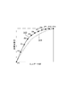
図3は、キャリブレーション処理部107で用いる1D−LUTを説明するための図であり、所定の種類の被記録媒体の所定の色の色材に対応するものである。即ち、被記録媒体の種類毎、そして色材の色毎にこのようなテーブルが存在する。図3において、横軸は図2のパッチを印刷させる際の色材色信号の入力データ値であり、縦軸は印刷されたパッチ画像の印刷濃度値である。破線301で示す曲線は、前述のキャリブレーション目標値データ(基準値)を示す。既知のタイプの被記録媒体(既知メディア)のキャリブレーション目標データについては予めプリンタ内のメモリに複数の入力データ値に対応付けられた濃度値として登録されているものとする。実線302で示す曲線は、実機印刷濃度データを示す。実機印刷濃度データは図2のパッチをプリンタで実際に印刷させ、それを読取装置によって読み取らせてその濃度を測定することで得られる。実機印刷濃度データP1〜P11が、パッチの各色材の0%〜100%の部分の濃度を測定する(場合によっては演算処理も行う)ことによって得られる。図3の例では、実機印刷濃度データは、基準値に対して吐出量が多いなどの理由で濃度が全体的に高く、また中間濃度部でより濃く印刷されている例を示している。キャリブレーション処理部107では実機印刷濃度データが基準値の印刷濃度となるように色材色別のコントーン(連続階調)色材信号を変換補正するための補正パラメータを算出し、パッチ以外の通常の画像の印刷の際、補正パラメータによって印刷データを補正してから印刷を行う。なお、印刷データの補正に代えて、あるいはそれに加えてインクの吐出量等を制御することによって補正を行うようにしてもよい。
FIG. 3 is a diagram for explaining the 1D-LUT used in the
次に以上説明したプリンタを含むシステム構成について説明する。図4は上記プリンタを含む2セットの印刷システムの構成を示すブロック図である。 Next, a system configuration including the printer described above will be described. FIG. 4 is a block diagram showing the configuration of a two-set printing system including the printer.
図4において、第1の印刷システムは、ホストPC401、プリンタ407、測色器415を有する一方、第1の印刷システムと通信可能に接続された第2の印刷システムはホストPC、プリンタ407を有するが測色器415は有さない。なお、ここでは説明の簡単のため2セットの印刷システムのみを示したが、ネットワーク等を介して第1の印刷システム、第2の印刷システムを複数設けるようにしてもよい。ネットワークとしてはLAN(ローカルエリアネットワーク)、インターネットなど種々の形態での接続が可能である。
In FIG. 4, the first printing system includes a
ホストPC401は、汎用的なパーソナルコンピュータによって実現可能であり、ソフトウェアのインストールにより後述する種々の処理を実行可能である。ホストPC401は、プリンタ407、測色器415とネットワークあるいはローカルインタフェースを介して互いに通信可能に接続される。ホストPC401は、UI(ユーザインタフェース)402、CPU403、RAM404、記憶装置405、データ入出力部406を有する。
The
UI402は、ユーザからの操作入力を受け付けるキーボード、ポインティングデバイス等の入力装置やユーザに提供すべき情報の表示を行うディスプレイを含む。CPU403は、ホストPC401の動作やプリンタ407、測色器415の動作の制御を行う。RAM404は、CPU403のワークエリアとして使用されたり、印刷システムにおける処理のための設定値等を記憶したりする。記憶装置405は大容量の不揮発性メモリであり、CPU403が実行する制御プログラム、プリンタ407で印刷させるための印刷データ、自印刷システムにおける処理に必要な各種データを記憶する。各種データには、例えば、各種画像処理パラメータ、プリントエンジンの制御パラメータ、調整パラメータ、センサ部制御データ、測色器制御データなどが含まれる。後述する処理は記憶装置405に記憶されたプログラムをCPU403がRAM404にロードし、それを実行することによってなされる。記憶装置405はホストPC401に内蔵されたものとしても外付けにしたものでもよい。データ入出力部406は自印刷システム外部(他の印刷システム等)との間のデータの入出力を制御する。データ入出力部406は、例えば第1の印刷システムと第2の印刷システムの間でキャリブレーション用のデータの交換を行うことが可能である。これにより例えば未知メディアのキャリブレーション用のデータを他の印刷システムから取得してキャリブレーションを行うことが可能となる。
The
プリンタ407は、図1〜3を用いて説明したプリンタに対応する。プリンタ407は、データ転送部408、プリンタ制御部409、画像処理部410、印刷部411、センサ補正部412、センサ部413、センサ補正情報記憶部414を有する。
The
データ転送部408は、ホストPC401から印刷データを受け取り、印刷データから画像データと画像処理パラメータを取り出す。そしてこの画像データと画像処理パラメータを画像処理部410に送る。またホストPC401から送られてくるプリンタの調整データ、プリンタ制御データ、センサ部制御データをプリンタ制御部409に送る。また、データ転送部408はプリンタ407の種々の情報をホストPC401に送る。
The
プリンタ制御部409は、CPU、メモリ、プリンタ制御用ハードウェア(ASIC等)等を含み、メモリに記憶されている制御プログラムに従ってCPUによりプリンタ407の動作の制御を行ったり、ハードウェアを用いたプリンタ407の動作の制御を行う。プリンタ制御部409はデータ転送部408を介して受け取ったプリンタ制御データに従ってプリンタ407による印刷の制御を行い、センサ部制御データに従ってセンサ部413、センサ補正部412による測色の制御を行う。
The
画像処理部410は、図1を用いて説明した画像処理部に対応し、印刷部411は前述のプリントエンジンに対応する。印刷部411は、インク吐出機構、被記録媒体(シート)の収納部、シート供給機構、シート搬送機構などを含む。印刷部411は、画像信号I/F101を介して出力された色材色信号またはキャリブレーション処理部107を介して出力された画像データに基づきインクの吐出、シートの搬送を制御してシート上の画像をプリントする。このときの色材色信号、画像データは画像処理部410または印刷部411において2値化処理が行われた後、印刷処理が行われる。ただし、印刷部411が1画素につき3値以上とした画像データに従った印刷を行うことができる場合、それに応じた変換がなされるものとしてもよい。また、印刷部411はプリンタ制御部409からの制御により、調整データに従った調整やプリンタ制御データに従った処理も行う。調整データに従った調整には、シート搬送ピッチの調整や記録ヘッドの高さの調整などが含まれる。プリンタ制御データに従った処理にはインク吐出量の制御などが含まれる。
The
センサ部413は、印刷部411により印刷された画像を読み取り、画像の濃度を測定するための読取センサである。センサ補正部412は、センサ部413による読み取り結果に基づきキャリブレーション処理部107によって補正を行わせるための補正値の算出を行う。センサ補正情報記憶部414は、プリンタ407のメモリの所定のエリアに、センサ補正部412が補正値を算出する際に用いる情報を記憶する。
The
次に、センサ部413、センサ補正部412、センサ補正情報記憶部414の補正情報を用いた補正処理について説明する。図7はこれを説明するための図である。
Next, correction processing using the correction information in the
図7(a)は、センサ部413を用いてシート上のパッチ画像を読み取る際の外観の概略図である。シート701に図2に示したキャリブレーションパッチの画像(パッチ画像)702が印刷されたものをプリンタ407にセットし、測色の指示がなされると測色処理が開始される。パッチ画像702が印刷されたシート701は所定間隔で順次搬送される。また図7(a)に示されているようにキャリッジ703にセンサ部413に対応するセンサ部材704が取り付けられている。キャリッジ703はシートの搬送方向とは直交する方向に走査され、このときセンサ部材704によってパッチ画像702を順次読み取る。従ってプリンタ制御部409はセンサ部制御データに従ってセンサ部材704を制御する際、キャリッジ703やシート搬送機構の制御も行う。
FIG. 7A is a schematic diagram of an external appearance when a patch image on a sheet is read using the
図7(b)はセンサ部413(センサ部材704)による読取(測色)処理を説明するための図である。センサ部材704は、光源として赤色LED705、緑色LED706、青色LED707を有し、また各光源からシート701に向けて照射された光の反射光を受光するフォトダイオードなどの受光素子708を有する。LEDの発光色は、測定する色材の色によって濃度識別レンジの広い補色の色あるいは補色に近い色の光源を選択する。即ち、測定する色材がシアン、淡シアンの場合は、光源として赤色LED705を選択し、同様にマゼンタ、淡マゼンタ、黒の場合は、緑色LED706を、黄の場合は、青色LED707をそれぞれ選択して測定を行う。センサ部材704の受光特性は、各光源(LED)705〜707の発光分光特性と受光素子708の受光感度特性に依存することになる。しかし、本実施形態では受光素子708として安定した受光感度特性を有するフォトダイオードを用いるものとし、LEDの発光分光特性がセンサ部材704の個体差に依存するものとする。従って、本実施形態におけるセンサ補正情報に含まれるセンサ受光特性情報はLEDの発光分光特性で代用することとする。
FIG. 7B is a diagram for explaining reading (colorimetry) processing by the sensor unit 413 (sensor member 704). The
図7(c)は各LEDの発光分光特性としての分光強度分布を示す。図7(c)において破線で示す曲線は各LEDの基準となる分光強度を示しており、予めプリンタ407のメモリに記憶されている情報に基づくものである。実線で示す曲線は各LED705〜707を1つずつ発光させ、その光を分光放射輝度計を用いて測定し、ピークの放射輝度で正規化した分光強度の例を示している。図中、709は赤色LEDの基準となる分光強度を示し、710は緑色LEDの基準となる分光強度を示し、711は青色LEDの基準となる分光強度を示す。また、712は赤色LED705を発光させた際の反射光を受光素子708で実測した分光強度、同様に713は緑色LED706について実測した分光強度、714は青色LED707について実測した分光強度をそれぞれ示す。このように実測した分光強度は基準値に対して個体差が含まれることがあり、この個体差を補正しつつキャリブレーション補正を行う。ここでは発光分光特性として一定間隔の波長単位での光強度を発光分光特性の情報としてプリンタ407のメモリに記憶するものとするが、これに代えてピーク波長と所定の光強度における波長幅を示す情報を用いるようにしてもよい。即ち、基準LEDの特性値をP1からP3の値とし、所定光強度での波長幅をW1からW3の値を発光分光特性の情報としてもよい。またこれに限らず各LEDの発光分光特性を特定できるものであれば種々の形態の情報としてもよい。
FIG. 7C shows a spectral intensity distribution as an emission spectral characteristic of each LED. A curve indicated by a broken line in FIG. 7C indicates the spectral intensity serving as a reference for each LED, and is based on information stored in the memory of the
センサ補正情報記憶部414には、メディア関連情報としてプリンタ407にセット(装着)されている被記録媒体(メディア)について実測したキャリブレーション用の実機印刷濃度データと各種メディアに対するキャリブレーション目標値データが記憶される。これらのデータはキャリブレーション処理部107で使用される。また、メディア関連情報には、メディアの種類毎にパッチ画像702を測色器415によって実測した結果を示す色材毎の分光反射率特性情報も含まれる。測色器415による分光反射率特性の測定については後述する。またセンサ補正情報記憶部414には、センサ部関連情報として上記した各LEDの基準センサ受光特性を示す基準センサ受光特性情報、実測した各LEDの受光特性である実機センサ受光特性情報が記憶される。これらの情報のうち、既知メディアに対応するキャリブレーション目標値データ、基準センサ受光特性情報は、予めプリンタ407のメモリに記憶されており、その他の情報は実測した結果をメモリに記憶する。例えば未知メディアに対応する各種情報は、自システム(装置)で実測して新たにメモリに記憶したり、他システム(装置)からデータ転送部408を介して受信してメモリに記憶したりする。また、自システム(装置)で実測して取得した未知メディアに対応する各種情報を、データ転送部408を介して送信して、他システム(装置)に登録することも可能である。これによって新たな未知メディアに対するキャリブレーションが可能となる。
In the sensor correction
図8は、センサ補正情報記憶部414に記憶される各種情報の概念図を示す。図8では各種情報をそれぞれの情報に対応する関数のグラフの形態で概念的に示しているが、センサ補正情報記憶部414には、所定の間隔で離散された実数として記憶される。
FIG. 8 is a conceptual diagram of various information stored in the sensor correction
図8において既知メディアをメディアA〜メディアG、未知メディアをメディアXと表している。各メディアはメディアの材質や加工形態等の種類毎に区別され、メディアの種類として普通紙、光沢紙などがある。 In FIG. 8, known media are represented as media A to G, and unknown media are represented as media X. Each medium is distinguished according to the type of media material, processing form, etc., and there are plain paper, glossy paper, etc. as media types.
また、色材の分光反射率特性情報は全てのメディアの種類について取得しておく必要はなく、適宜必要なメディアの情報のみ記憶させておくようにしてもよい。また、いくつかの種類のメディアについて分光反射率特性を取得し、他の種類のメディアについては取得済みのメディアの分光反射率特性に基づき補間処理によって算出してもよい。またパッチ画像702の読み取りに際しても全ての濃度について読み取るのではなく、いくつかを読み取って補間処理によって算出してもよい。
Further, the spectral reflectance characteristic information of the color material need not be acquired for all types of media, and only necessary media information may be stored as appropriate. Alternatively, spectral reflectance characteristics may be acquired for some types of media, and other types of media may be calculated by interpolation processing based on the spectral reflectance characteristics of the acquired media. Also, when reading the
次にセンサ補正部412による補正方法について説明する。図9はこれを説明するための図である。図9(a)はセンサ補正部412の構成の詳細を示すブロック図である。センサ部413から出力された輝度データ(輝度値P(X))が濃度値変換部901に入力される。濃度値変換部901は紙白部のセンサ読み取り輝度値P(0)とP(X)によって(式1)により濃度値D(X)を求める。紙白部のセンサ読み取り輝度値はシート701の色材の載っていない箇所(紙白部)や基準白板などを読み取った場合の輝度値である。濃度値変換部901によって輝度値から変換された濃度値D(X)は差分1D−LUT処理部902に入力される。なお、図9(a)においてセンサ部413から取得した輝度値に対して、先に差分1D−LUT処理902による処理を行い、その後濃度値変換部901により輝度値から濃度値へ変換するようにしてもよい。即ち、濃度値変換部901と差分1D−LUT処理部902の処理順を逆としてもよい。
D(X)=−log(P(X)/P(0)) ――――― (式1)
Next, a correction method by the
D (X) =-log (P (X) / P (0)) ――――― (Formula 1)
差分1D−LUT処理部902は、以下で説明する手順により差分1D−LUT生成部904で生成される1D−LUTデータを、差分1D−LUT設定部903によって設定されたLUTを用いて処理する。差分1D−LUT生成部904では、図8に示した対象とする基準センサ受光特性情報と実機センサ受光特性情報と対象とするメディアの色材の分光反射率特性情報に基づいて生成される。以下の説明では、色材としてシアンの場合を例に説明するが他の色材についても同様に行う。色材の分光反射率特性情報は、紙白(0%)から10%刻みのパッチ画像の実機のセンサ出力としての輝度値に対する分光反射率特性情報である。この情報に従いセンサ受光特性情報と分光反射率特性から求めた濃度値が図9(b)の横軸となる。センサ部413のセンサ受光特性に対応するLEDの分光発光特性を用いて、実機センサ(センサ部413)の特性αx(λ)、基準センサの特性をα0(λ)(但し、λ=380nmから700nm)とし、N%(但し、N=0から100)の分光反射率特性をR(N,λ)とする。実機センサの濃度値Dx(N)は、(式2)によって求められ、基準センサの濃度値D0(N)は、(式3)によって求められる。
Dx(N)=−log(Σ(αx(λ)×R(N,λ))/(Σ(αx(λ)×R(0,λ)))) ――― (式2)
D0(N)=−log(Σ(α0(λ)×R(N,λ))/(Σ(α0(λ)×R(0,λ)))) ――― (式3)
The differential 1D-
Dx (N) = − log (Σ (αx (λ) × R (N, λ)) / (Σ (αx (λ) × R (0, λ)))) —— (Formula 2)
D0 (N) = − log (Σ (α0 (λ) × R (N, λ)) / (Σ (α0 (λ) × R (0, λ)))) ――― (Formula 3)
図9(b)の縦軸はセンサ輝度出力値から求めた(式1)によって求められる濃度値である。上記の実機センサでのパッチ画像の測定結果のデータをA0からA10としその間を補間した実線の曲線で表したものが実機センサの濃度特性905である。また、(式3)によって求められる基準センサの濃度値から同様に求めたセンサ出力値からの濃度値をB0からB10として示す。この曲線情報をもとに(式3)の結果を用いて得た基準センサでの濃度特性が906である。基準センサの情報で求めたセンサ受光特性とメディアの分光反射率特性から算出したD0(1)での実機センサでの濃度特性905での濃度値がDx(1)上の値で出力されるC1が基準センサでの出力となる。同様にA2からA10、B2からB10についても同様に算出することにより、基準センサでの濃度特性906が求められる。この実機センサの濃度特性905が基準センサの濃度特性906になるように補正するためのデータが差分1D−LUT生成部で生成される。
The vertical axis in FIG. 9B is the density value obtained by (Equation 1) obtained from the sensor luminance output value. The
測色器415は、基準白板等を用いて校正を行い、パッチ画像の分光反射率を読み取り(全波長を含む白色光を発光し、単波長域の反射を所定波長毎に測定する)、その結果を分光反射率特性情報として出力する。即ち、センサ部413が所定波長毎の分光反射率を測定できないのに対し、測色器415はそれを測定可能である。測色器415でパッチ画像702を測定して得たメディア毎の色材の分光反射率特性情報がセンサ補正情報記憶部414に記憶される。
The colorimeter 415 performs calibration using a reference white plate or the like, reads the spectral reflectance of the patch image (emits white light including all wavelengths, and measures reflection in a single wavelength region for each predetermined wavelength), and The result is output as spectral reflectance characteristic information. That is, while the
測色器415による測色により得た色材の分光反射率特性情報は、他のシステム(装置)に送信することが可能である。これにより測色器415を有さないシステム(装置)あるいは測色器415による測色が行えないシステム(装置)においても精度の高いキャリブレーション処理を実施することが可能である。ただし、本実施形態における印刷システム(装置)は測色器415により得られる情報を用いずセンサ部413によって測定できる情報を用いたキャリブレーションも(補正精度は落ちるが)可能である。
The spectral reflectance characteristic information of the color material obtained by color measurement by the colorimeter 415 can be transmitted to another system (apparatus). As a result, it is possible to perform highly accurate calibration processing even in a system (apparatus) that does not include the colorimeter 415 or a system (apparatus) that cannot perform colorimetry using the colorimeter 415. However, the printing system (apparatus) according to the present embodiment can perform calibration using information that can be measured by the
なお、図4で示した第1の印刷システムは、ホストPC401、プリンタ407、測色器415で構成されるものとしたが、このような形態以外の構成でも同様の結果は得ることができる。即ち、図5に示すように測色器407をプリンタ407に内蔵(または装着)させてもよい。この場合、プリンタ制御部409が測色器415の動作を制御することになる。また、ホストPC401が行う処理をプリンタ407において行うようにしてもよい。即ち、図6に示すように、ホストPC401の402〜406に相当する構成を、422〜426としたコントローラユニット421を設けた第1の印刷装置420として構成することもできる。この場合、プリンタ制御部409に代わり、CPU423が第1の印刷装置420(測色器415も含む)の動作を制御することになる。そして、測色器415を含まない第2の印刷装置などの他の装置とは、直接ネットワークを介して、あるいはホストPC427を介して情報の送受信を行うことになる。各印刷装置とホストPC427とはローカルインタフェースを介してまたはネットワークを介して接続される。また、ホストPC401を含む形態では、ホストPC401によってプリンタ407の動作も含めた制御を行ってもよいし、プリンタ制御部409によってデータ転送以外の動作の制御を行ってもよいし、ホストPC401とプリンタ制御部409と適宜処理を分担してもよい。また図6の例のように1台の印刷装置(プリンタ)がデータ転送も含めた全ての動作の制御を行うようにしてもよい。また、以上の例において、測色器415を備える装置においてセンサ部413も備えるものとしたが、測色器415によってセンサ部413で測定すべき情報の測定が行える場合、センサ部413を備えないようにしてもよい。つまり図4〜6に示したシステムあるいは装置の構成は一例であり、他の形態のものとしてもよい。
The first printing system shown in FIG. 4 is configured by the
次に以上説明した印刷システムあるいは印刷装置におけるキャリブレーション処理について説明する。以下のフローチャートは、当該処理を実行するシステム(装置)の記憶装置(メモリ)に記憶されている制御プログラムをCPUが実行することによりなされる処理を示す。記憶装置としては記憶装置405、プリンタ制御部409内のメモリ、記憶装置425が対応する。CPUとしてはCPU403、プリンタ制御部409内のCPU、CPU423が対応する。ただし、全ての処理をソフトウェアにより実行する必要はなく、処理の一部または全部をASIC等のハードウェアで実現するようにしてもよい。また、CPUも1つのCPUで全ての処理を行うものに限らず、複数のCPUが適宜連携をしながら処理を行うものとしてもよい。
Next, calibration processing in the printing system or printing apparatus described above will be described. The following flowchart shows processing performed when the CPU executes a control program stored in a storage device (memory) of a system (device) that executes the processing. A
図10は上述した実機印刷濃度データをセンサ補正情報記憶部414に登録する際の処理の流れを示すフローチャートである。このフローチャートの実行にあたり、UI402または422からキャリブレーション処理の実行指示や当該処理の実行に必要なパラメータ等の入力が行われる。
FIG. 10 is a flowchart showing the flow of processing when registering the above-described actual machine print density data in the sensor correction
S1001では、キャリブレーション処理を行うためのメディア(被記録媒体)の設定を行う。ここではUI402または422を用いて既知メディアの情報を読み出し、メディアの種類の設定を行う。これによりメディアの種類に応じた各種パラメータが記憶装置422、プリンタ制御部409のメモリまたは記憶装置425から読み出される。
In step S1001, a medium (recording medium) for performing calibration processing is set. Here, information on known media is read using the
次にS1002では、S1002で設定されたメディアの種類に応じたパラメータを用いて図2に示したキャリブレーション用のパッチチャートの画像(パッチ画像702)をS1001で設定されたメディア上に印刷部411により印刷する。このパッチチャートも記憶装置422、プリンタ制御部409のメモリまたは記憶装置425から読み出され図1に示したように画像信号I/F101から出力された後、102〜107の処理を経ずに、ハーフトーニング処理などが施され印刷される。
In step S1002, the calibration patch chart image (patch image 702) shown in FIG. 2 is printed on the medium set in step S1001 using the parameters corresponding to the medium type set in step S1002. To print. This patch chart is also read from the
次にS1003では、センサ部413を用いてS1002で印刷したパッチチャートの画像の読み取りを行う。即ち、各色のLED705〜707を用いて図2のパッチチャートの各色材の各濃度の画像を読み取る。
In step S <b> 1003, the patch chart image printed in step S <b> 1002 is read using the
次にS1004では、基準センサの受光特性情報、実機センサの受光特性情報、対象のメディアの分光反射率情報を用いて実機センサの受光特性が基準センサの受光特性となるよう図9を用いて述べたように変換する。 Next, in S1004, receiving characteristic information of the reference sensor, described with reference to FIG. 9 to the light receiving characteristic information of actual sensor, the light receiving characteristic of the actual sensor using the spectral reflectance data of the target medium is received characteristics of the reference sensor Convert as follows.
次にS1005では、前述のように10%間隔で濃度を変化させたパッチ画像に対応するS1004で求めた基準センサの濃度出力値に対する補間処理を行い、実機印刷濃度データを生成する。 In step S1005, interpolation processing is performed on the density output value of the reference sensor obtained in step S1004 corresponding to the patch image whose density is changed at 10% intervals as described above, thereby generating actual printing density data.
次にS1006では、S1005で生成した実機印刷濃度データをセンサ補正情報記憶部414に記憶する。
In step S1006, the actual print density data generated in step S1005 is stored in the sensor correction
次に未知メディアのキャリブレーション情報の追加処理について説明する。図11はこの処理の流れを示すフローチャートである。 Next, processing for adding calibration information for unknown media will be described. FIG. 11 is a flowchart showing the flow of this process.
S1101では追加するメディアの設定を行う。ここでは未知メディアなので、UI402または422を用いて追加するメディアの種類の入力を行うことになる。そしてキャリブレーション処理に必要なパラメータを読み出すことになるが、メディアの特性に非依存である基準センサの分光受光特性情報、実機センサの分光受光特性情報はよいが、メディアの特性に依存するキャリブレーション目標濃度値、メディアの分光反射率情報を新規に取得する必要がある。そこで未知メディアのキャリブレーション情報の追加では、この処理における印刷状態が基準となる。即ち、図8のメディア関連情報として、実機印刷濃度データとキャリブレーション目標値が同じものとして登録することなる。そして、S1105の実機センサでの測定前に、測色器415によって色材の分光反射率特性情報を取得し(S1103)、S1101で設定したメディアを特定する情報(メディア名)と対応付けて登録しておく。それ以外は図10で示した処理と同様であるが、S1106の基準濃度値「基準センサ値への変換」は、S1103で測定し、S1104で登録した未知メディアの分光反射率を用いる。
In S1101, the media to be added is set. Since the medium is unknown here, the type of media to be added is input using the
次に測色器415を有するシステム(装置)において作成した未知メディアについてのキャリブレーション情報を他のシステム(装置)に送信する処理について説明する。図12は測色器415を備えるシステム(装置)における処理の流れを示すフローチャートである。 Next, a process for transmitting calibration information about an unknown medium created in a system (apparatus) having the colorimeter 415 to another system (apparatus) will be described. FIG. 12 is a flowchart showing a flow of processing in a system (apparatus) including the colorimeter 415.
S1201〜1208は図11の処理と同様に行われる。S1209では、UI402または422を用いて送信先となる測色器415を備えない、測色器415による測色を行えない、あるいは測色器415による測色結果を有さない印刷システムあるいは印刷装置を指定する。そして、測色器415による測色結果に基づく未知メディア(追加メディアX)のキャリブレーション目標値データ、色材の分光反射率特性情報をキャリブレーション情報として指定された印刷システム(装置)に対して送信する。
Steps S1201 to 1208 are performed in the same manner as the processing in FIG. In step S <b> 1209, a printing system or printing apparatus that does not include the colorimeter 415 serving as a transmission destination using the
S1209で送信先として指定された印刷システム(装置)は、図13に示すフローチャートに従って追加メディアXのキャリブレーション情報をセンサ補正情報記憶部414に登録する。即ち、S1301において分光反射率情報、キャリブレーション目標値データを受信し、S1302において受信した情報をセンサ補正情報記憶部414に登録する。S1303〜1308は、図11に示した処理と同様に今回登録した情報を用いてキャリブレーションを行う。
The printing system (apparatus) designated as the transmission destination in S1209 registers the calibration information of the additional medium X in the sensor correction
なお、以上の説明において測色器を備えるシステム(装置)から分光反射率情報とキャリブレーション目標値データ(目標濃度情報)とを送信し、測色器を備えないシステム(装置)が受信したこれらの情報と自身で測定した濃度情報とによってキャリブレーションを行うものとした。しかしながら、測色器を備えるシステム(装置)から目標濃度情報を送信せずに、測色器を備えないシステム(装置)が受信した分光反射率情報に従って目標濃度情報を算出するようにしてもよい。 In the above description, spectral reflectance information and calibration target value data (target density information) are transmitted from a system (apparatus) equipped with a colorimeter, and received by a system (apparatus) not equipped with a colorimeter. Calibration was performed using the above information and the concentration information measured by itself. However, the target density information may be calculated according to the spectral reflectance information received by the system (apparatus) that does not include the colorimeter without transmitting the target density information from the system (apparatus) that includes the colorimeter. .
以上のように、本実施形態によれば、1つの印刷システム(装置)が備えている測色器によってパッチ画像を測色することによって得たキャリブレーション用の情報を他の1または複数の印刷システム(装置)に転送し、それを利用することが可能となる。従って多数の印刷システム(装置)において測色器を備えることなく、精度の高いキャリブレーション処理を行うことができる。また、所定波長にピークを持った光源と受光素子とで構成される安価なセンサ部(カラーセンサ)を有し、複数バンドのカラーフィルタまたは回折格子を備えた測色器を有さない印刷システム(装置)においても測色器を用いたキャリブレーションが行えるので、複数の印刷システム(装置)を安価なコストで導入可能となる。このときセンサ部の個体差も実測した各光源の発光強度に応じた補正を行うので精度の高いキャリブレーションが行える。また、キャリブレーション情報の送受信に際しては測色器による測定に基づき得た情報を送受信させ、センサ部による測定に基づき得た情報を送受信させないことにより、送受信されるキャリブレーション情報の量を減らすことができ通信トラフィックの増大を抑えることができる。そして、キャリブレーション情報を受け取った側では、自身のセンサ部による測定結果と受信したキャリブレーション情報とに基づきキャリブレーションを行うので、自身の印刷状態に応じた精度の高いキャリブレーションを行うことができる。また、新たな種類の被記録媒体を使用する際も、測色器を有したシステム(装置)によって容易に新たなキャリブレーション情報を作成し、他のシステム(装置)にも反映させることができる。なお、キャリブレーション情報を送信する際、例えば送信先の印刷システム(装置)がセンサ部も有していない、あるいはセンサ部による測定が行えない場合などに、測色器による測定結果に基づく情報とともに自身のセンサ部による測定結果に基づく情報を送信するようにしてもよい。そしてこれを受信した側ではこれらの情報に基づいてキャリブレーション情報を登録し、キャリブレーションの際に使用する。これにより、受信側での負荷等を軽減させることもできる。 As described above, according to the present embodiment, the calibration information obtained by measuring the color of the patch image by the colorimeter provided in one printing system (apparatus) is printed in one or more other colors. It is possible to transfer to the system (device) and use it. Therefore, it is possible to perform highly accurate calibration processing without providing a colorimeter in many printing systems (apparatuses). Also, a printing system that has an inexpensive sensor unit (color sensor) composed of a light source and a light receiving element having a peak at a predetermined wavelength, and does not have a colorimeter equipped with a multiband color filter or diffraction grating. Since the calibration using the colorimeter can also be performed in the (apparatus), a plurality of printing systems (apparatuses) can be introduced at a low cost. At this time, the individual differences of the sensor units are also corrected in accordance with the actually measured emission intensity of each light source, so that highly accurate calibration can be performed. In addition, when transmitting / receiving calibration information, the amount of calibration information transmitted / received can be reduced by transmitting / receiving information obtained based on measurement by the colorimeter and not transmitting / receiving information obtained based on measurement by the sensor unit. And increase in communication traffic can be suppressed. Then, the calibration information is received on the side receiving the calibration information based on the measurement result of the sensor unit and the received calibration information, so that the calibration can be performed with high accuracy according to the printing state of the calibration information. . Also, when using a new type of recording medium, new calibration information can be easily created by a system (apparatus) having a colorimeter and reflected on other systems (apparatuses). . When transmitting calibration information, for example, when the destination printing system (apparatus) does not have a sensor unit, or when measurement by the sensor unit cannot be performed, along with information based on the measurement result by the colorimeter You may make it transmit the information based on the measurement result by own sensor part. The receiving side registers calibration information based on these pieces of information and uses it for calibration. As a result, the load on the receiving side can be reduced.
なお、以上の実施形態において、印刷システム、ホストPC、プリンタのそれぞれをキャリブレーション情報の生成、取得を行う画像処理装置として機能させることができる。
In the above embodiment, each of the printing system, the host PC, and the printer can function as an image processing apparatus that generates and acquires calibration information.
Claims (11)
前記受信手段により受信した分光反射率情報と、基準センサの受光特性情報と、実機センサの受光特性情報と、に基づき、前記画像処理装置の実機センサの受光特性が前記基準センサの受光特性となるように補正するための補正値を生成する生成手段と、
前記対象となる被記録媒体上に印刷されたパッチ画像を印刷部に印刷させる印刷制御手段と、
前記印刷部に印刷させたパッチ画像を前記実機センサを用いて読取ることにより濃度データを取得する取得手段と、
前記生成手段により生成された補正値と、前記取得手段により取得した濃度データとに基づいて、前記対象とする被記録媒体を用いた前記印刷部のキャリブレーションのためのセンサの補正処理を行う処理手段と、
を有することを特徴とする画像処理装置。 Receiving means for receiving a patch image printed on a recording medium of interest, the spectral reflectance information measured by reading using a measuring instrument from the external device,
Based on the spectral reflectance information received by the receiving means, the light reception characteristic information of the reference sensor, and the light reception characteristic information of the actual sensor, the light reception characteristic of the actual sensor of the image processing device becomes the light reception characteristic of the reference sensor. Generating means for generating a correction value for correcting
Print control means for printing a patch image printed on the target recording medium on a printing unit;
Acquisition means for acquiring density data by reading a patch image printed on the printing unit using the actual sensor;
A correction value generated by the generation unit, on the basis of the density data acquired by the acquisition unit, correction processing for the sensor for the printing of the calibration using the recording medium according to the subject Means,
An image processing apparatus comprising:
前記取得手段により取得した濃度データ、前記生成手段により生成した補正値、及び目標濃度情報に基づき、前記処理手段によるセンサの補正処理及びキャリブレーションを行うことを特徴とする請求項1〜3のいずれか1項に記載の画像処理装置。 The receiving means further receives target density information,
The sensor correction process and calibration by the processing unit are performed based on the density data acquired by the acquisition unit, the correction value generated by the generation unit, and target density information. The image processing apparatus according to claim 1.
前記基準センサの受光特性情報は、前記基準センサの光源の発光分光特性の情報であり、The light reception characteristic information of the reference sensor is information on emission spectral characteristics of the light source of the reference sensor,
前記実機センサの受光特性情報は、前記実機センサの光源の発光分光特性の情報であることを特徴とする請求項1〜5のいずれか1項に記載の画像処理装置。The image processing apparatus according to claim 1, wherein the light reception characteristic information of the real machine sensor is information of emission spectral characteristics of a light source of the real machine sensor.
前記基準センサの受光特性情報は、前記基準センサの光源の発光分光特性の情報及び前記受光素子の受光特性の情報に基づく情報であり、The light receiving characteristic information of the reference sensor is information based on information on emission spectral characteristics of a light source of the reference sensor and information on light receiving characteristics of the light receiving element,
前記実機センサの受光特性情報は、前記実機センサの光源の発光分光特性の情報及び前記受光素子の受光特性の情報に基づく情報であることを特徴とする請求項1〜5のいずれか1項に記載の画像処理装置。6. The light receiving characteristic information of the actual machine sensor is information based on information on emission spectral characteristics of a light source of the actual machine sensor and information on light receiving characteristics of the light receiving element. The image processing apparatus described.
前記受信手段により受信した分光反射率情報と、基準センサの受光特性情報と、実機センサの受光特性情報と、に基づき、前記画像処理装置の実機センサの受光特性が前記基準センサの受光特性となるように補正するための補正値を生成する生成工程と、
前記対象となる被記録媒体上に印刷されたパッチ画像を印刷部に印刷させる印刷工程と、
前記印刷部に印刷させたパッチ画像を前記実機センサを用いて読取ることにより濃度データを取得する取得工程と、
前記生成工程において生成された補正値と、前記取得工程において取得した濃度データとに基づいて、前記対象とする被記録媒体を用いた前記印刷部のキャリブレーションのためのセンサの補正処理を行う処理工程と、
を有することを特徴とする画像処理方法。 A reception step of receiving the patch image printed on a recording medium, the spectral reflectance information measured by reading using a measuring instrument from the external device in question,
Based on the spectral reflectance information received by the receiving means, the light reception characteristic information of the reference sensor, and the light reception characteristic information of the actual sensor, the light reception characteristic of the actual sensor of the image processing device becomes the light reception characteristic of the reference sensor. A generation step of generating a correction value for correction as follows :
A printing step for causing a printing unit to print a patch image printed on the target recording medium;
An acquisition step of acquiring density data by reading a patch image printed on the printing unit using the real machine sensor;
Processing for performing sensor correction processing for calibration of the printing unit using the target recording medium based on the correction value generated in the generation step and the density data acquired in the acquisition step Process,
An image processing method comprising:
Priority Applications (3)
| Application Number | Priority Date | Filing Date | Title |
|---|---|---|---|
| JP2011257431A JP6061459B2 (en) | 2011-11-25 | 2011-11-25 | Image processing apparatus, method, and program |
| EP12007835.7A EP2597857B1 (en) | 2011-11-25 | 2012-11-20 | Image processing apparatus and method for performing calibration for printing, program, and storage medium |
| US13/683,334 US9277076B2 (en) | 2011-11-25 | 2012-11-21 | Image processing apparatus and method for performing calibration for printing |
Applications Claiming Priority (1)
| Application Number | Priority Date | Filing Date | Title |
|---|---|---|---|
| JP2011257431A JP6061459B2 (en) | 2011-11-25 | 2011-11-25 | Image processing apparatus, method, and program |
Publications (3)
| Publication Number | Publication Date |
|---|---|
| JP2013111775A JP2013111775A (en) | 2013-06-10 |
| JP2013111775A5 JP2013111775A5 (en) | 2015-01-15 |
| JP6061459B2 true JP6061459B2 (en) | 2017-01-18 |
Family
ID=47520650
Family Applications (1)
| Application Number | Title | Priority Date | Filing Date |
|---|---|---|---|
| JP2011257431A Active JP6061459B2 (en) | 2011-11-25 | 2011-11-25 | Image processing apparatus, method, and program |
Country Status (3)
| Country | Link |
|---|---|
| US (1) | US9277076B2 (en) |
| EP (1) | EP2597857B1 (en) |
| JP (1) | JP6061459B2 (en) |
Families Citing this family (10)
| Publication number | Priority date | Publication date | Assignee | Title |
|---|---|---|---|---|
| US9224074B2 (en) * | 2011-08-11 | 2015-12-29 | Consolidated Graphics, Inc. | System and method for tuning device link profiles for color printing |
| US9204016B2 (en) | 2011-08-11 | 2015-12-01 | Consolidated Graphics, Inc. | In-process color management system and method for digital color printing |
| KR20150063652A (en) * | 2013-12-02 | 2015-06-10 | 삼성전자주식회사 | Image forming apparatus, method for calibration of print density and and computer-readable recording medium |
| JP2016095214A (en) * | 2014-11-14 | 2016-05-26 | セイコーエプソン株式会社 | Colorimetric device, printing control device, and printing control method |
| US9491328B2 (en) * | 2015-02-28 | 2016-11-08 | Xerox Corporation | System and method for setting output plex format using automatic page detection |
| JP6606355B2 (en) * | 2015-05-29 | 2019-11-13 | キヤノン株式会社 | Information processing apparatus, information processing method, and program |
| JP6907630B2 (en) * | 2017-03-21 | 2021-07-21 | 株式会社リコー | Image forming apparatus, image forming system and calibration method |
| US11057528B2 (en) * | 2018-09-27 | 2021-07-06 | Canon Kabushiki Kaisha | Information processing apparatus, method and storage medium |
| JP7229782B2 (en) | 2019-01-09 | 2023-02-28 | キヤノン株式会社 | Measuring device and image forming system |
| JP7501027B2 (en) * | 2020-03-24 | 2024-06-18 | 富士フイルムビジネスイノベーション株式会社 | Information processing device and program |
Family Cites Families (39)
| Publication number | Priority date | Publication date | Assignee | Title |
|---|---|---|---|---|
| US5162841A (en) * | 1989-10-11 | 1992-11-10 | Fuji Photo Film Co., Ltd. | Exposure controlling apparatus |
| JP2855008B2 (en) * | 1990-10-03 | 1999-02-10 | 富士写真フイルム株式会社 | Image processing method and apparatus |
| US5363318A (en) * | 1992-03-23 | 1994-11-08 | Eastman Kodak Company | Method and apparatus for adaptive color characterization and calibration |
| EP0570003B1 (en) * | 1992-05-15 | 2000-08-02 | Toyota Jidosha Kabushiki Kaisha | Three-dimensional automatic gonio-spectrophotometer |
| US5579090A (en) * | 1994-01-12 | 1996-11-26 | Canon Kabushiki Kaisha | In an image processing system, an image processing apparatus and method for stabilizing output image quality by controlling image forming parameters |
| BE1008076A3 (en) * | 1994-02-15 | 1996-01-09 | Agfa Gevaert Nv | COLOR NEGATIVE SCANNING AND TRANSFORMATION IN COLORS OF ORIGINAL scene. |
| US5537516A (en) * | 1994-03-15 | 1996-07-16 | Electronics For Imaging, Inc. | Method for calibrating a color printer using a scanner for color measurements |
| US5838465A (en) * | 1994-12-02 | 1998-11-17 | Hitachi, Ltd. | Color compensating method of color image and color image generating apparatus |
| US5856876A (en) * | 1995-04-06 | 1999-01-05 | Canon Kabushiki Kaisha | Image processing apparatus and method with gradation characteristic adjustment |
| JP3255218B2 (en) | 1995-10-20 | 2002-02-12 | 富士ゼロックス株式会社 | Printer with color proofing function |
| US7728845B2 (en) * | 1996-02-26 | 2010-06-01 | Rah Color Technologies Llc | Color calibration of color image rendering devices |
| US6459425B1 (en) * | 1997-08-25 | 2002-10-01 | Richard A. Holub | System for automatic color calibration |
| US6697167B1 (en) * | 1997-08-29 | 2004-02-24 | Canon Kabushiki Kaisha | Image processing apparatus and method |
| US6156465A (en) * | 1999-04-12 | 2000-12-05 | Cymbolic Sciences Inc. | Crosstalk correction |
| JP2001239731A (en) * | 1999-12-21 | 2001-09-04 | Fuji Photo Film Co Ltd | Printing method of calibration pattern and printer |
| JP4115098B2 (en) * | 2001-03-28 | 2008-07-09 | 株式会社リコー | Image forming apparatus, masking coefficient calculation method, and recording medium recording masking coefficient calculation program |
| JP2004145859A (en) * | 2002-07-19 | 2004-05-20 | Imaging Solutions Ag | Optimization of image data using color management |
| US7423778B2 (en) * | 2003-08-01 | 2008-09-09 | Ecole Polytechnique Federale De Lausanne (Epfl) | Prediction model for color separation, calibration and control of printers |
| US7069164B2 (en) * | 2003-09-29 | 2006-06-27 | Xerox Corporation | Method for calibrating a marking system to maintain color output consistency across multiple printers |
| JP2005229371A (en) * | 2004-02-13 | 2005-08-25 | Seiko Epson Corp | Print profile setting device, print profile setting system, print profile setting method, and print profile setting program |
| JP4217643B2 (en) * | 2004-03-18 | 2009-02-04 | キヤノン株式会社 | Image density correction method and image density correction system |
| JP4332123B2 (en) * | 2005-01-18 | 2009-09-16 | 富士フイルム株式会社 | Patch color comparison device, patch color comparison program, and patch color comparison system |
| JP4607723B2 (en) * | 2005-01-19 | 2011-01-05 | 株式会社リコー | Image forming apparatus |
| US8717647B2 (en) * | 2005-10-13 | 2014-05-06 | Hewlett-Packard Development Company, L.P. | Imaging methods, imaging device calibration methods, imaging devices, and hard imaging device sensor assemblies |
| JP4739017B2 (en) * | 2005-12-28 | 2011-08-03 | キヤノン株式会社 | Color evaluation processing method, color evaluation processing device, computer program, and recording medium |
| JP4895357B2 (en) * | 2006-03-31 | 2012-03-14 | キヤノン株式会社 | Image forming apparatus and image forming method |
| US8270049B2 (en) * | 2006-08-01 | 2012-09-18 | Xerox Corporation | System and method for high resolution characterization of spatial variance of color separation misregistration |
| JP4766691B2 (en) * | 2006-12-18 | 2011-09-07 | キヤノン株式会社 | Gradation correction table creation method and apparatus |
| JP5188082B2 (en) * | 2007-03-26 | 2013-04-24 | キヤノン株式会社 | Method, apparatus and program for creating color conversion definition for image output device |
| JP5415729B2 (en) * | 2007-09-10 | 2014-02-12 | キヤノン株式会社 | Image processing method and image processing apparatus |
| JP5147390B2 (en) * | 2007-12-28 | 2013-02-20 | キヤノン株式会社 | Color processing apparatus and method |
| JP5254674B2 (en) * | 2008-06-13 | 2013-08-07 | キヤノン株式会社 | Image processing method and image processing apparatus |
| US8733874B2 (en) * | 2009-06-23 | 2014-05-27 | Canon Kabushiki Kaisha | Printing apparatus and image processing method |
| JP5652022B2 (en) * | 2009-08-07 | 2015-01-14 | 株式会社リコー | Color material amount determination table creation method and color material amount measurement device |
| CN102597744B (en) * | 2009-09-03 | 2016-09-07 | 澳大利亚国家Ict有限公司 | Illumination spectra is recovered |
| JP5751812B2 (en) * | 2009-12-22 | 2015-07-22 | キヤノン株式会社 | Image processing system, image processing method, and printed matter |
| US9066072B2 (en) * | 2010-07-20 | 2015-06-23 | Semiconductor Components Industries, Llc | Systems and methods for calibrating image sensors |
| JP5947502B2 (en) * | 2011-08-11 | 2016-07-06 | キヤノン株式会社 | Spectral colorimeter and image forming apparatus |
| US8807696B2 (en) * | 2012-03-27 | 2014-08-19 | Canon Kabushiki Kaisha | Colorimetric apparatus and colorimetric method |
-
2011
- 2011-11-25 JP JP2011257431A patent/JP6061459B2/en active Active
-
2012
- 2012-11-20 EP EP12007835.7A patent/EP2597857B1/en active Active
- 2012-11-21 US US13/683,334 patent/US9277076B2/en active Active
Also Published As
| Publication number | Publication date |
|---|---|
| US20130135686A1 (en) | 2013-05-30 |
| EP2597857B1 (en) | 2020-05-20 |
| JP2013111775A (en) | 2013-06-10 |
| EP2597857A2 (en) | 2013-05-29 |
| EP2597857A3 (en) | 2017-02-22 |
| US9277076B2 (en) | 2016-03-01 |
Similar Documents
| Publication | Publication Date | Title |
|---|---|---|
| JP6061459B2 (en) | Image processing apparatus, method, and program | |
| US8259369B2 (en) | Color characterization or calibration targets with noise-dependent patch size or number | |
| US7069164B2 (en) | Method for calibrating a marking system to maintain color output consistency across multiple printers | |
| US7633647B2 (en) | Method for spatial color calibration using hybrid sensing systems | |
| JP4976348B2 (en) | Matching print system color print job output | |
| US8400677B2 (en) | Image processing apparatus, image forming system, image processing method and computer readable medium for calibrating profiles of multiple sheets | |
| KR101148381B1 (en) | Method for generating a color chart | |
| US7315394B2 (en) | Calibration method for an imaging device | |
| US20130208289A1 (en) | Color measuring device, image forming apparatus, color measuring method, and color measuring system | |
| US9979860B2 (en) | Image forming apparatus, non-transitory computer-readable storage medium storing color-conversion control program, and color-conversion control method | |
| JP6349741B2 (en) | Look-up table generation method and color conversion device | |
| US8314978B2 (en) | Halftone independent device characterization accounting for colorant interactions | |
| US20090290171A1 (en) | Automated color adjustment | |
| JP3848877B2 (en) | Color tone control method and apparatus for printing press | |
| JP2009071617A (en) | Image processor, image processing method and program | |
| US7595910B2 (en) | Method for making a dot for dot proof | |
| GB2431791A (en) | Validating printing by scanning colour patches on printed modified original image | |
| JP5429000B2 (en) | Color measuring device, color measuring method, and color measuring program | |
| US8605268B2 (en) | Multi-channel sensor for measuring colorants of prints | |
| JP2016203472A (en) | Recording device and determination method | |
| JP5963511B2 (en) | Data processing apparatus, data processing method and program thereof | |
| JP4785676B2 (en) | Method and system for creating conversion table for color matching profile | |
| JP3592152B2 (en) | Image processing method, apparatus and recording medium | |
| JP2005319751A (en) | Printer and calibration method | |
| US11946804B2 (en) | Method of fast spectral color measuring |
Legal Events
| Date | Code | Title | Description |
|---|---|---|---|
| A521 | Request for written amendment filed |
Free format text: JAPANESE INTERMEDIATE CODE: A523 Effective date: 20141125 |
|
| A621 | Written request for application examination |
Free format text: JAPANESE INTERMEDIATE CODE: A621 Effective date: 20141125 |
|
| A131 | Notification of reasons for refusal |
Free format text: JAPANESE INTERMEDIATE CODE: A131 Effective date: 20151027 |
|
| A521 | Request for written amendment filed |
Free format text: JAPANESE INTERMEDIATE CODE: A523 Effective date: 20151225 |
|
| A131 | Notification of reasons for refusal |
Free format text: JAPANESE INTERMEDIATE CODE: A131 Effective date: 20160517 |
|
| A521 | Request for written amendment filed |
Free format text: JAPANESE INTERMEDIATE CODE: A523 Effective date: 20160629 |
|
| TRDD | Decision of grant or rejection written | ||
| A01 | Written decision to grant a patent or to grant a registration (utility model) |
Free format text: JAPANESE INTERMEDIATE CODE: A01 Effective date: 20161115 |
|
| A61 | First payment of annual fees (during grant procedure) |
Free format text: JAPANESE INTERMEDIATE CODE: A61 Effective date: 20161213 |
|
| R151 | Written notification of patent or utility model registration |
Ref document number: 6061459 Country of ref document: JP Free format text: JAPANESE INTERMEDIATE CODE: R151 |