JP6355398B2 - Image processing apparatus, image processing method, and program - Google Patents
Image processing apparatus, image processing method, and program Download PDFInfo
- Publication number
- JP6355398B2 JP6355398B2 JP2014082125A JP2014082125A JP6355398B2 JP 6355398 B2 JP6355398 B2 JP 6355398B2 JP 2014082125 A JP2014082125 A JP 2014082125A JP 2014082125 A JP2014082125 A JP 2014082125A JP 6355398 B2 JP6355398 B2 JP 6355398B2
- Authority
- JP
- Japan
- Prior art keywords
- recording
- image
- dot count
- element groups
- recording element
- Prior art date
- Legal status (The legal status is an assumption and is not a legal conclusion. Google has not performed a legal analysis and makes no representation as to the accuracy of the status listed.)
- Active
Links
Images


Classifications
-
- H—ELECTRICITY
- H04—ELECTRIC COMMUNICATION TECHNIQUE
- H04N—PICTORIAL COMMUNICATION, e.g. TELEVISION
- H04N1/00—Scanning, transmission or reproduction of documents or the like, e.g. facsimile transmission; Details thereof
- H04N1/04—Scanning arrangements, i.e. arrangements for the displacement of active reading or reproducing elements relative to the original or reproducing medium, or vice versa
-
- H—ELECTRICITY
- H04—ELECTRIC COMMUNICATION TECHNIQUE
- H04N—PICTORIAL COMMUNICATION, e.g. TELEVISION
- H04N1/00—Scanning, transmission or reproduction of documents or the like, e.g. facsimile transmission; Details thereof
- H04N1/40—Picture signal circuits
- H04N1/401—Compensating positionally unequal response of the pick-up or reproducing head
- H04N1/4015—Compensating positionally unequal response of the pick-up or reproducing head of the reproducing head
-
- B—PERFORMING OPERATIONS; TRANSPORTING
- B41—PRINTING; LINING MACHINES; TYPEWRITERS; STAMPS
- B41J—TYPEWRITERS; SELECTIVE PRINTING MECHANISMS, i.e. MECHANISMS PRINTING OTHERWISE THAN FROM A FORME; CORRECTION OF TYPOGRAPHICAL ERRORS
- B41J2/00—Typewriters or selective printing mechanisms characterised by the printing or marking process for which they are designed
- B41J2/005—Typewriters or selective printing mechanisms characterised by the printing or marking process for which they are designed characterised by bringing liquid or particles selectively into contact with a printing material
- B41J2/01—Ink jet
- B41J2/21—Ink jet for multi-colour printing
- B41J2/2132—Print quality control characterised by dot disposition, e.g. for reducing white stripes or banding
-
- H—ELECTRICITY
- H04—ELECTRIC COMMUNICATION TECHNIQUE
- H04N—PICTORIAL COMMUNICATION, e.g. TELEVISION
- H04N1/00—Scanning, transmission or reproduction of documents or the like, e.g. facsimile transmission; Details thereof
- H04N1/00681—Detecting the presence, position or size of a sheet or correcting its position before scanning
Description
本発明は、記録媒体上に画像を記録するための画像処理装置、画像処理方法及びプログラムに関する。 The present invention relates to an image processing apparatus, an image processing method, and a program for recording an image on a recording medium.
インクジェット記録装置は、高密度・高速な記録動作が可能であり、ランニングコストが安く静かな記録方式であることなどの優位点を有しており、様々な形態の出力機器として製品化されている。また、近年は、普通紙を用いるオフィス文書の印刷だけではなく、銀塩写真の画質に迫る高画質な写真画像の印刷にも利用されるようになっている。インクドットの小滴化や複数の濃度の色材の利用などによって、画像の粒状性を低減させたことがインクジェット記録による画質向上の大きな要因の一つといえる。 Inkjet recording devices have advantages such as high-density and high-speed recording operations, low running costs, and a quiet recording method, and are commercialized as various types of output devices. . In recent years, it has been used not only for printing office documents using plain paper but also for printing high-quality photographic images that approach the image quality of silver halide photographs. It can be said that one of the major factors for improving the image quality by ink jet recording is to reduce the granularity of the image by reducing the size of the ink dots and using color materials having a plurality of densities.
ここで、インクジェット記録によって高画質な画像を得られない要因の一つとして、記録ヘッドの吐出特性のばらつきに起因する画像の濃度ムラが挙げられる。複数の記録素子(ノズル)を備えるインクジェット記録装置では、各記録素子の吐出特性がばらつくことにより、記録画像に濃度ムラが発生することがある。この記録素子の吐出特性のばらつきは、インクの着弾位置の変動と吐出量変動に分類され、インクを加熱する発熱ヒータの発熱量のばらつきやノズル口径のばらつきなどが要因として挙げられる。また、経年変化による発熱ヒータの発熱量変動や、使用環境の違いによるインクの粘性の変動によっても、各記録素子から吐出されるインクの量に差が生じることがある。 Here, as one of the factors that make it impossible to obtain a high-quality image by inkjet recording, there is density unevenness of the image due to variations in ejection characteristics of the recording head. In an inkjet recording apparatus including a plurality of recording elements (nozzles), density unevenness may occur in a recorded image due to variations in the ejection characteristics of each recording element. Variations in the ejection characteristics of the recording elements are classified into variations in the ink landing position and variations in the ejection amount, and can be cited as factors such as variations in the amount of heat generated by the heater that heats the ink and variations in the nozzle diameter. In addition, there may be a difference in the amount of ink ejected from each recording element due to fluctuations in the amount of heat generated by the heater due to aging, and fluctuations in ink viscosity due to differences in the usage environment.
記録ヘッドの吐出特性のばらつきの影響を軽減する方法として、ヘッドシェーディング補正が知られている。ヘッドシェーディング補正は、記録ヘッドを用いて印字したテストパターンを読み取り、濃度ムラが低減されるように各ノズルに対応する画像データの濃度値を補正する。一方、記録素子列における吐出量ばらつきは常に一定ではなく、記録素子毎の吐出履歴により個々で独立に変化する。従って、濃度ムラ低減効果を維持するためには、定期的にヘッドシェーディング補正を実行する必要がある。 Head shading correction is known as a method for reducing the influence of variations in ejection characteristics of recording heads. In the head shading correction, a test pattern printed using a recording head is read, and the density value of image data corresponding to each nozzle is corrected so that density unevenness is reduced. On the other hand, the discharge amount variation in the printing element array is not always constant, but varies independently depending on the discharge history for each printing element. Therefore, in order to maintain the density unevenness reduction effect, it is necessary to periodically perform head shading correction.
特許文献1には、記録濃度が変化し易い記録ヘッドの使用初期では頻繁にヘッドシェーディング補正を行い、ある記録発数に達し、記録ヘッドの記録濃度が変化し易い期間が終了した後にヘッドシェーディング補正の頻度を下げることが記載されている。具体的には、ノズル列方向に領域を分割し、領域毎にヘッド使用初期の記録濃度が変化し易い範囲の記録発数に有るかどうかを判断し、ヘッドシェーディング補正頻度を決定することが記載されている。
In
特許文献1に記載の方法のように、ノズル群毎の記録発数を求めようとした場合、実際に記録素子を駆動した回数をカウントする方法と、画像データのドット数をカウントする方法が考えられる。このとき、前者の駆動回数を用いてノズル群毎の記録発数のカウントを行うと、ノズルが高密度化された現在のプリンタシステムでは大きな処理負荷がかかり、さらには、プリンタシステム全体でのコストアップにつながってしまう。一方、後者の画像データのドット数をカウントする方法では、マルチパス記録のように複数回の走査で複数のノズル群を用いて画像を記録する場合には、全ての走査で記録されるドット数の合計がわかるだけで、各ノズル群が記録するドット数を得ることができない。
As in the method described in
このような課題を鑑み、本願発明は、複数の記録素子を有する記録ヘッドと、記録媒体と、の少なくとも一方を複数回走査させ、それぞれ前記記録ヘッド内の一部の記録素子から構成される複数の記録素子群によって記録媒体上の単位領域に画像を記録するために、前記単位領域に記録する画像に対応する画像データを処理する画像処理装置であって、前記画像に対応するドットの数を示す第1ドットカウント値を取得する第1取得手段と、前記複数の記録素子群に対応し、前記画像の記録のために前記複数の記録素子群それぞれを使用する比率に対応する複数の寄与率を取得する第2取得手段と、前記第1ドットカウント値と前記複数の寄与率に基づいて、前記複数の記録素子群それぞれにおける複数の第2ドットカウント値を取得する第3取得手段と、前記複数の第2ドットカウント値に基づいて、前記画像データを補正するための濃度補正データを生成する必要があるかどうかを判定する判定手段と、を備えることを特徴とする。 In view of such a problem, the present invention has a plurality of recording elements each composed of a part of recording elements in the recording head by scanning at least one of a recording head having a plurality of recording elements and a recording medium a plurality of times. In order to record an image in a unit area on a recording medium by the recording element group, an image processing apparatus that processes image data corresponding to an image to be recorded in the unit area, the number of dots corresponding to the image is set. A first acquisition means for acquiring a first dot count value, and a plurality of contribution ratios corresponding to the plurality of recording element groups and corresponding to a ratio of using each of the plurality of recording element groups for recording the image Second acquisition means for acquiring a plurality of second dot count values for each of the plurality of recording element groups based on the first dot count value and the plurality of contribution rates. An acquisition unit, the plurality of on the basis of the second dot count value, characterized in that it comprises a determination means for determining whether it is necessary to generate a density correction data for correcting the image data.
上記構成により、プリンタシステムに大きな負荷をかけずに比較的簡易な構成によって、記録ヘッドのノズル列に含まれる複数のノズル群毎のドットカウント値を得ることができ、それによってヘッドシェーディングの必要性を高精度に判断することができる。 With the above configuration, it is possible to obtain the dot count value for each of a plurality of nozzle groups included in the nozzle array of the recording head with a relatively simple configuration without imposing a heavy load on the printer system, thereby the necessity of head shading. Can be determined with high accuracy.
(第1の実施形態)
以下、図面を参照して、本発明の一実施形態を説明する。
(First embodiment)
Hereinafter, an embodiment of the present invention will be described with reference to the drawings.
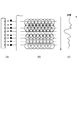
まず、図1及び図2を用いて、記録ヘッドの吐出量ばらつきに起因する濃度ムラを抑えるための方法の一つとして、同じ場所を複数回走査することで記録を行うマルチパス記録について説明する。 First, using FIG. 1 and FIG. 2, multi-pass printing in which printing is performed by scanning the same place a plurality of times will be described as one method for suppressing density unevenness due to the ejection amount variation of the print head. .
図1は、記録ヘッドを用いて1回の走査で画像を記録する、所謂1パス印字を行った場合の一例を示している。図1(a)は、記録ヘッドに設けられた8個の記録素子から吐出されるインク滴の体積や方向がばらついていることを示している。このような吐出特性のばらつきを有する記録ヘッドを用いて1パス印字を行うと、図1(b)に示すように、記録媒体上の印字領域には、記録素子に対応した印字行ごとに大きさや着弾位置がばらついたドットが形成されてしまう。記録媒体上に形成されるドットの大きさのばらつきや着弾位置のばらつきは、図1(b)の中央部分に見られるような白地の部分や、また必要以上にドットが重なりあった部分が生じる。図1(c)は、図1(b)に示したドット形成がなされた画像の濃度分布を示している。このような画像濃度の差が、画像の白スジや黒スジとして認識されてしまう。 FIG. 1 shows an example in which so-called one-pass printing is performed in which an image is recorded by one scan using a recording head. FIG. 1A shows that the volume and direction of ink droplets ejected from eight recording elements provided in the recording head vary. When one-pass printing is performed using a recording head having such a variation in ejection characteristics, as shown in FIG. 1B, the print area on the recording medium is large for each print line corresponding to the recording element. Dots with different sheath landing positions are formed. The variation in the size of dots formed on the recording medium and the variation in the landing position are caused by a white background as seen in the central portion of FIG. 1B or a portion where dots overlap more than necessary. . FIG. 1C shows the density distribution of the image on which the dots shown in FIG. 1B have been formed. Such a difference in image density is recognized as a white stripe or black stripe in the image.
図2は、図1に示した記録ヘッドを用いてマルチパス記録を行った場合の説明図である。図2(a)に示すように、図1で示した印字領域に対して記録ヘッドを3回走査させることにより画像を形成する。このとき、印字領域の半分である縦4画素分の2つの領域には、それぞれ2回の走査で画像が形成される。2回の走査で画像を記録する場合、記録ヘッドの8個の記録素子は、上の4個と下の4個の各領域に分けられ、1つの記録素子が1回の走査で印字するドットは、所望の画像データを所定の方法に従って、約半分に間引いたものである。そして、記録媒体を4画素分搬送することで、1回目の走査で用いられた記録素子と異なる記録素子を用いて、残りの半分の間引いた画像データによって補完的にドットを形成する。図2(b)および(c)は、記録された画像の濃度であり、図1の場合に比べて濃度ムラが低減されている。このように、マルチパス記録方式では、記録ヘッドが走査する方向(主走査方向)の1ドットライン(以降、ラスターと呼ぶ)を異なる複数の記録素子を用いて記録するため、各記録素子の吐出特性のばらつきの影響を軽減できる。 FIG. 2 is an explanatory diagram when the multi-pass printing is performed using the print head shown in FIG. As shown in FIG. 2A, an image is formed by causing the recording head to scan the print area shown in FIG. 1 three times. At this time, an image is formed in two areas corresponding to four vertical pixels, which is half of the print area, by scanning twice. When an image is recorded by two scans, the eight recording elements of the recording head are divided into the upper four areas and the lower four areas, and one recording element prints dots in one scan. Is obtained by thinning out desired image data by about half according to a predetermined method. Then, by transporting the recording medium by four pixels, dots are complementarily formed by the image data thinned out by the remaining half using recording elements different from the recording elements used in the first scan. 2B and 2C show the density of the recorded image, and density unevenness is reduced as compared with the case of FIG. As described above, in the multi-pass printing method, since one dot line (hereinafter referred to as a raster) in the scanning direction (main scanning direction) of the printing head is printed using a plurality of different printing elements, the ejection of each printing element is performed. The influence of characteristic variation can be reduced.
図3は、本実施形態に用いるインクジェット記録装置の内部構成を示す斜視図である。キャリッジ(CR)モータ32を駆動源としたタイミングベルト33の移動に伴い、記録ヘッドを搭載したキャリッジ31が、ガイドシャフト34に案内支持されながら、図の主走査方向に往復移動する。フレキシブルケーブル35は、キャリッジ31の移動に追従しながら、装置本体の基板と記録ヘッドを電気的に接続している。搬送ローラ対36は、記録媒体37を挟持するとともに、その回転に伴って記録媒体37を、主走査方向と交差する所定方向(副走査方向)に搬送する。記録データに従って記録ヘッドがインクを吐出しながらキャリッジ31が主走査方向に移動する主走査と、搬送ローラ対36の回転に伴う搬送動作と、を交互に繰り返すことにより、段階的に記録媒体上に画像が形成される。
FIG. 3 is a perspective view showing the internal configuration of the ink jet recording apparatus used in the present embodiment. Along with the movement of the
図4は、本実施形態で用いる記録ヘッド41の記録素子側を示す模式図である。記録ヘッド41は、1インチ当たり1200個の密度で1280個の記録素子(以下、ノズルとも称する)が副走査方向に並ぶ記録素子列を、インク色毎に備えている。シアンインクを吐出するノズル列41C、マゼンタインクを吐出するノズル列41M、イエローインクを吐出するノズル列41Y、およびブラックインクを吐出するノズル列41BKが記録ヘッド41の主走査方向に並んでいる。ノズル列41C、41M、41Y、41BKのそれぞれは、1インチ当たり600個の密度でノズルが並ぶ2列のノズル列が、1/1200インチずれて千鳥状に配置されたものである。この2つの列を1つのノズル列と見なすことで、記録媒体上に1インチ当たり1200個のドットを形成することができる。各ノズルから吐出されるインク滴の量(吐出量)は約4.5plである。ただし、ブラックインクは高濃度を実現するため、他色のインクよりも吐出量を多く設定してもよい。本実施形態の記録ヘッドは、熱エネルギーを利用してインクを吐出する記録ヘッドであり、ノズル内に熱エネルギーを発生するための電気熱変換体を備える。尚、インクを吐出する方式は熱エネルギーを利用する方法に限るものではなく、圧電素子によってインクを吐出する方法等、他の方式であっても良い。
FIG. 4 is a schematic diagram showing the recording element side of the
このような記録ヘッド41を主走査方向に走査しながらインクを吐出することにより、主走査方向に2400dpi(dot/inch)、副走査方向に1200dpiの記録密度でドットを形成することができる。また、CMYK4色のインクを吐出する記録ヘッド41は、各色で独立に構成されていても良いし、一体的に構成されていても良い。また、上記4色のインクの他に、粒状性向上を目的として淡シアンインクや淡マゼンタインクを追加してもよく、発色向上を目的としてレッドインク、グリーンインク、ブルーインクを追加してもよい。
By ejecting ink while scanning the
(画像処理システムの構成例)
次に、インクジェット記録装置の記録制御を実行するための制御構成について説明する。図5は、図3に示したインクジェット記録装置の制御系の構成を説明するためのブロック図である。まず、スキャナやデジタルカメラ等の画像入力機器501やハードディスク等の各種記憶媒体に保存されている多値画像データが、画像入力部502に入力される。画像入力部502は、記録装置外部に接続されたホストコンピュータであり、インターフェイス回路503を介して、記録装置である画像出力部504に対して記録すべき画像情報を転送する。画像入力部502には、画像データを転送する際に必要なCPU505や、記憶素子(ROM506)が配置されている。ホストコンピュータの形態としては、情報処理装置としてのコンピュータとするほか、イメージリーダなどの形態とすることもできる。
(Configuration example of image processing system)
Next, a control configuration for executing recording control of the ink jet recording apparatus will be described. FIG. 5 is a block diagram for explaining the configuration of the control system of the ink jet recording apparatus shown in FIG. First, multi-valued image data stored in various storage media such as an
記録制御部507の内部には、CPU508を始め、制御プログラムなどを記憶した記憶素子(ROM509)や、各種画像処理を実施する際のワークエリアとなるRAM510が配置されている。ROM509は、CPU508の制御プログラムや記録動作に必要なパラメータなどの各種データを格納している。本実施形態のROM509は、EEPROM(Electric Erasable Pragaramable ROM)であり、電気的に書き換えることが可能である。また、記録装置の電源を切ったとしても情報が保存される。RAM510は、CPU508のワークエリアとして使用されると共に、画像入力部502から受信した画像データや生成した記録データなどの各種データの一時保管等を行う。また、ROM509には、図6を用いて後述するテーブルとしてのLUT(ルックアップテーブル)602、604、606や寄与率テーブル104が格納されている。RAM510には、パッチを記録するためのパッチデータが格納されている。尚、602、604、606のルックアップテーブルや寄与率テーブル104をRAM510に格納してもよく、パッチデータをROM509に格納してもよい。
Inside the
記録制御部507は、画像入力部502より転送された多値の入力画像データを、後述する画像処理を施して2値画像データへと変換する。また、記録制御部507は入出力ポート511を備えており、搬送ユニットにおけるキャリッジ(CR)モータ32、搬送(LF)モータ512、記録ヘッド41の各駆動回路513、514、515が接続される。さらに、入出力ポート511には、カラーパッチの測定や記録媒体の検出に用いるカラーセンサ516、周辺環境の温湿度を検出する温湿度センサ517などのセンサ類が接続される。そして、記録制御部507において変換された2値画像データに基づき、記録ヘッド41の各記録素子から記録媒体にインクを付与するにより画像を形成する。
The
本実施形態では、プリンタシステムにおける負荷の少ない比較的簡易な手段により、画像データのドットカウント値と後述する寄与率とから、ノズル列を任意の数で分割したノズル群単位でのドットカウント値を算出する。このような寄与率を用いたドットカウント値算出方法を用いることにより、ヘッドシェーディング補正に用いる補正データを生成するタイミングを高精度に判定することが可能となる。 In the present embodiment, the dot count value for each nozzle group obtained by dividing the nozzle row into an arbitrary number is calculated from the dot count value of the image data and the contribution rate described later by a relatively simple means with a small load in the printer system. calculate. By using a dot count value calculation method using such a contribution rate, it is possible to determine the timing for generating correction data used for head shading correction with high accuracy.
図6は、図5に示した記録制御部507で実行される処理を示すフローチャートである。本フローは、記録装置がホストコンピュータから印刷ジョブを受信するとスタートする。尚、印刷ジョブには、記録すべき画像の画像データの他に、マルチパス記録におけるパス数、余白の量もしくははみだし量、画像の倍率などの画像を記録する記録モードの記録条件を示す記録条件情報が含まれる。そして、画像データと記録条件情報に基づいて、この記録制御部507は上記特徴的な処理を実行可能な制御部を構成する。この制御部を構成する記録制御部507において、画像データの画素ごとにどのノズルを使用するのかが決定される。詳細は後述するが、印刷ジョブを受信すると、図6の処理と並行して、図11の処理が実行され、図6のステップS605のヘッドシェーディング補正処理において用いる寄与率テーブルが生成される。尚、寄与率テーブルは、印刷ジョブを受信してからステップS605の処理が実行されるまでの間に生成されればよく、処理のタイミングは限定されない。
FIG. 6 is a flowchart showing processing executed by the
記録装置が印刷ジョブを受信すると、ステップS601において、各色8bitで構成される入力画像データを、C、M、Y、およびKの濃度信号に変換する色変換処理が行われる。具体的には、3次元の色変換ルックアップテーブル602を参照し、画素ごとに、入力画像データを、プリンタが利用可能な複数のインク色の多階調データ(CMYKデータ)に変換する。 When the printing apparatus receives a print job, in step S601, a color conversion process is performed to convert input image data composed of 8 bits for each color into C, M, Y, and K density signals. Specifically, referring to a three-dimensional color conversion lookup table 602, for each pixel, input image data is converted into multi-tone data (CMYK data) of a plurality of ink colors that can be used by the printer.
色変換ルックアップテーブルの次元数は、ステップS601の色変換処理に入力する入力画像データの成分(要素)の数を示している。ただし、この色変換ルックアップテーブル602には、特定且つ離散的なRGB信号に対する濃度信号しか保持されておらず、各色256段階で表現されるRGBの全ての組み合わせに対応していない。従って、保持されていない領域のRGB信号に対しては、保持している複数のデータを用いて、補間処理で求める。ここでは公知の補間処理方法を用いるため、詳細な説明は省略する。ステップS601の色変換処理によって変換された多階調データ(CMYKデータ)の値は、入力値である入力画像データと同様に8bitで表現され、256段階の階調値を有する濃度値として出力される。 The number of dimensions of the color conversion lookup table indicates the number of components (elements) of input image data input to the color conversion process in step S601. However, this color conversion lookup table 602 holds only density signals for specific and discrete RGB signals and does not correspond to all combinations of RGB expressed in 256 stages for each color. Therefore, the RGB signals in the area that is not retained are obtained by interpolation processing using a plurality of retained data. Since a known interpolation processing method is used here, a detailed description thereof is omitted. The value of the multi-gradation data (CMYK data) converted by the color conversion processing in step S601 is expressed by 8 bits similarly to the input image data as the input value, and is output as a density value having 256 gradation values. The
次に、ステップS603において、色変換が施されたCMYKデータを補正する、出力γ補正処理が行われる。ここでは、最終的に記録媒体で表現される光学濃度が入力される濃度信号に対し線形性を保つように、1次元の補正テーブルである1D−LUT604を参照してインク色毎にデータを補正する。この1D−LUT604は、標準的な記録特性を示す記録ヘッドを基準に生成されている。ここで出力されるC’M’Y’K’データは、入力画像データと同様に8bitの濃度値である。
Next, in step S603, output γ correction processing for correcting the CMYK data subjected to color conversion is performed. Here, the data is corrected for each ink color with reference to the 1D-
次に、ステップS605において、この8bitの濃度値に対して、HS補正用1次元LUT606と寄与率テーブル104を用いて濃度補正処理(ヘッドシェーディング補正処理)が行われ、新たなC’’M’’Y’’K’’データへと変換される。前述のステップS603の出力γ補正処理では、標準的な記録ヘッドに対応して作成された1D−LUTを用いているため、記録ヘッドの個体差もしくはノズル単位の記録特性のばらつきが生じてしまう。従って、ステップS605において、ノズル単位での記録特性のばらつきを補正するヘッドシェーディング補正(以下、HS補正とも称す)を行う。
Next, in step S605, density correction processing (head shading correction processing) is performed on the 8-bit density value using the HS correction one-
次に、ステップS608において、記録ヘッド41が記録可能なドットの記録位置を定めた1bitの2値画像データへと変換する2値化処理を行う。この2値化処理は、一般的な多値誤差拡散処理を採用することが出来る。ステップS609において、2値画像データを元に、後述するマスクパターン処理において使用するマスクパターンを選択し、走査毎の出力画像データを生成する。
Next, in step S608, binarization processing is performed to convert the recording position of dots that can be recorded by the
尚、ステップS601の色変換処理、ステップS603の出力γ補正処理、ステップS605のヘッドシェーディング補正処理、およびステップS608の2値化処理における最適な変換方法は、記録媒体の種類や記録する画像の種類等によって異なる。特に、色変換処理で用いられる3次元の色変換ルックアップテーブル(3D−LUT)602は、記録媒体の種類ごとに用意される。 Note that the optimum conversion method in the color conversion process in step S601, the output γ correction process in step S603, the head shading correction process in step S605, and the binarization process in step S608 is the type of recording medium and the type of image to be recorded. Depends on etc. In particular, a three-dimensional color conversion lookup table (3D-LUT) 602 used in the color conversion process is prepared for each type of recording medium.
図7を用いて、ステップS609のマスクパターン処理について具体的に説明する。マスクパターンは、記録制御部507内のROM509に格納されている。ステップS609のマスクパターン処理では、マスクパターンを用いて各色の画像データを記録走査毎に分割し、記録走査毎且つインク色毎のドットデータを生成する。
The mask pattern processing in step S609 will be specifically described with reference to FIG. The mask pattern is stored in the ROM 509 in the
画像データ71は、記録画像における単位画素の記録密度を表しており、ここでは50%である。この記録密度50%の画像画素に対して2値化処理が行われ、また同時に行った解像度変換によって4×2の記録画素となったものが、2値画像データ72に示されている。2値画像データ72において、ドットの記録を示す黒の画素が4画素、ドットの非記録を示す白の画素が4画素であり、記録密度が50%となる。本実施形態において、記録密度とは、1200dpi×1200dpiで配列する記録媒体上の画素のうち、実際にドットが記録される画素の割合を示す。すなわち、記録密度が50%とは、全ての画素のうち半分の画素にドットが記録されることを示す。
The
図中、73は、4回の記録走査によって画像を記録する4パスのマルチパス記録に用いられるマスクパターンの一例である。ドットの記録の許容または非許容を示す複数の画素領域によって構成されている。黒く示した領域がドットの記録を許容する記録許容画素を示しており、白く示した領域がドットの記録を許容しない非記録許容画素を示している。個々のマスクパターン73a〜73dは、記録許容率が均等な25%ずつである。互いに補完の関係を保っており、合計100%である。
In the figure,
ノズル列内のノズルは縦方向に4つの領域に区分される。各領域に含まれるノズルは、マスクパターン73のうち各領域に対応するマスクパターン73a〜73dと画像データに従ってドットを記録する。各走査について、マスクパターン73a〜73dと2値化処理後の2値画像データ72との論理積をとることにより、各走査で実際に記録する画素が決定される。74は、論理積の結果を示しており、各記録走査で記録される画素の位置を示したものを縦に並べている。これにより、記録走査ごとに1画素ずつ記録されることがわかる。例えば、2値画像データ72とマスクパターン73bとの論理積から、2回目の記録走査によって記録される出力画像データ74bが導き出される。つまり、2値画像データにおいて記録される画素データがあり、かつマスクパターンにおいて記録を許容された場合にのみドットを記録する。ここでは説明を簡単にするため4画素×8画素の領域を有するマスクパターンを示したが、マスクパターンは、主走査方向にも副走査方向にも更に大きな領域を有している。特に、副走査方向において、記録ヘッドのノズル列のノズル数とマスクパターンの画素数とを同一にするのが一般的である。
The nozzles in the nozzle row are divided into four regions in the vertical direction. The nozzles included in each region record dots according to the
(ヘッドシェーディング補正LUTの生成方法)
次に、図8を用いて、HS補正用1次元LUT606を生成する方法について説明する。ここでは、記録ヘッド41のノズル群毎にパッチの測定結果を取得し、記録ヘッドのノズル群毎の濃度値を取得する。本実施形態では、出力γ処理(ステップS603)の後、及び、2値化処理(ステップS608)の前に、ヘッドシェーディング補正処理(ステップS605)を行う。
(Method for generating head shading correction LUT)
Next, a method for generating the HS correction one-
図8は、ヘッドシェーディング補正を行うために必要な、記録ヘッド41のノズル群毎にパッチの測定結果を取得し、HS補正用1次元LUTを生成する処理を示すフローチャートである。まず、ステップS801において、画像入力部502のCPU505、または画像出力部504の操作パネル(不図示)等から、パッチを記録して濃度を測定するヘッドシェーディング補正実行命令が入力される。ヘッドシェーディング補正実行の命令が入力されると、ステップS802において、画像出力部504は、テストパターンを記録するための記録媒体を、給紙トレイから給紙する。記録ヘッド41による記録が可能な領域まで記録媒体を搬送すると、ステップS803において、記録媒体の副走査方向への搬送動作と、キャリッジモータ32を駆動したキャリッジ31の主走査方向への記録走査とを交互に行う。そして、パッチ記録手段としての記録ヘッド41が、記録媒体上に記録ヘッド41の各領域の濃度値を得るのに必要な数のパッチを含むテストパターンを記録する。
FIG. 8 is a flowchart showing a process for acquiring a patch measurement result for each nozzle group of the
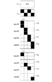
図9は、ステップS803で記録されるテストパターンの概略図である。本図では、各パッチを区別するために英字および数字を示しているが、実際には、各インク色に対応する、それぞれ一様な濃度のパッチである。本図において、各パッチに記載されているC、M、Y、BKの英字は、それぞれ、図4に示したノズル列41C、41M、41Y、41BKから吐出されたインクによって記録されたパッチを示す符号である。また、英字の隣に記載されている1〜5までの数字は、記録するカラーパッチの濃度階調をランク付けした数字である。ここでは、数字が大きいほど高濃度のパッチとする。例えば、パッチC1はシアンインクを吐出するノズル列41Cにより記録された濃度階調1のパッチである。なお、階調値は5値に限るものではない。また、数字の大きさと階調の高さが対応していなくてもよく、数字が小さいほど高濃度のパッチとしてもよい。
FIG. 9 is a schematic diagram of the test pattern recorded in step S803. In this figure, alphabets and numbers are shown to distinguish each patch, but in actuality, the patches have uniform densities corresponding to the respective ink colors. In this figure, the letters C, M, Y, and BK described in each patch indicate patches recorded by ink ejected from the
各パッチの副走査方向の長さは、記録ヘッドで記録可能な幅、すなわちノズル幅に対応している。各パッチにおいて、副走査方向における記録媒体の搬送の下流側(図の上側)からN行目の画像データは、記録ヘッド41において上からN個目のノズルを用いて記録される。例えば、記録されたパッチの副走査方向下流側1行目(上から1個目)は、記録ヘッドのノズル列の副走査方向下流側から1行目(上から1個目)のノズルを用いて記録される。そして、副走査方向下流側から2行目(上から2個目)は、ノズル列の副走査方向下流側から2行目(上から2個目)のノズルを用いて記録される。出力されたパッチを測定した測定結果に基づいて、ノズル群毎の濃度特性を取得することができる。
The length of each patch in the sub-scanning direction corresponds to the width that can be recorded by the recording head, that is, the nozzle width. In each patch, the image data of the Nth row from the downstream side (upper side in the drawing) of the conveyance of the recording medium in the sub-scanning direction is recorded by the
図8に戻り、ステップS804において、記録されたパッチを所定時間乾燥させるためのタイマーカウンタをスタートする。続いて、ステップS805において、カラーセンサ516を用いてパッチが記録されていない白レベル(記録媒体の地色)の反射光の強度を測定する。白レベルの測定結果は、この後に記録するパッチの濃度値算出を行う際の基準値として利用される。測定結果は、カラーセンサ516の光源であるLED毎にそれぞれ保持される。尚、パッチが記録されていない記録媒体の空白部分の濃度は、記録媒体の地色が測定され、白い記録媒体であれば地色は白色である。本実施形態においては、白い地色の記録媒体を用いる例について説明する。
Returning to FIG. 8, in step S804, a timer counter for drying the recorded patches for a predetermined time is started. Subsequently, in step S805, the
ステップS806において、乾燥タイマーのカウンタが所定時間経過したことが確認されると、ステップS807において、各パッチの反射光の強度を測定する。反射光強度の測定は、カラーセンサ516に搭載されているLEDのうち、濃度測定するインク色に適したLEDを点灯し、パッチの反射光を読み取ることにより行う。緑色LEDは、例えば、Mインクにより記録されたパッチ、およびパッチが記録されていない空白部分(白色)を測定する時に点灯する。青色LEDは、例えば、Yインク、Kインクにより記録されたパッチ、およびパッチが記録されていない空白部分(白色)を測定する時に点灯する。赤色LEDは、例えば、Cにより記録されたパッチ、およびパッチが記録されていない空白部分(白色)を測定する時に点灯する。また、各パッチの反射光強度の測定は、副走査方向において、連続的、あるいは、ノズルのピッチ単位で行う。なお、反射光の強度測定は1ノズル単位で行ってもよく複数ノズル単位で行ってもよい。本実施形態では、2ノズル単位で行う。
In step S806, when it is confirmed that the counter of the drying timer has passed for a predetermined time, the intensity of the reflected light of each patch is measured in step S807. The reflected light intensity is measured by turning on the LED suitable for the ink color whose density is to be measured among the LEDs mounted on the
パッチの読み取りが終了すると、ステップS808において、それぞれのパッチと空白部分(白色)の双方の出力値に基づいて、対応するノズル群毎にパッチの濃度値を算出する。尚、パッチを測定する際は、2ノズル単位の濃度値をまとめて読み取ってもよく、1ノズル単位で2カ所読み取り、2カ所の読み取り濃度値を平均化してもよい。読み取ったノズル群毎の濃度値は、記録制御部507のROM509またはRAM510に保存される。
When the reading of the patch is completed, in step S808, the density value of the patch is calculated for each corresponding nozzle group based on the output values of both the patch and the blank portion (white). When measuring a patch, the density values in units of two nozzles may be read collectively, or two places may be read in units of one nozzle, and the density values read in two places may be averaged. The read density value for each nozzle group is stored in the ROM 509 or the
ステップ809において、測定したノズル群毎の濃度値に基づいて、ヘッドシェーディング補正処理で用いるHS補正用1次元LUT606を生成する。HS補正用1次元LUT606とは、ノズル群毎の補正前の濃度値とターゲット値に補正した後の濃度値との対応関係を示した濃度補正データであり、ノズル群毎に独立に生成される。ターゲット値とは予め定められている所定の目標濃度のことである。記録されたパッチの濃度値(測定値)がターゲット値に近づくように、ノズル群毎に画像データの濃度値を補正する。なお、予め精度の良好なインクジェット記録装置および記録ヘッドを用いてパッチを記録し、濃度測定した際に得られた値をターゲット値として採用してもよい。生成されたHS補正用1次元LUT606と、後述する寄与率と、を用いて、ラスター単位で、補正前の画像データの濃度値から補正後の画像データの濃度値が決定する。
In
HS補正用1次元LUT606は、記録制御部507のCPU508あるいは画像入力部502のCPU505において生成される。記録媒体の種類や解像度ごとに生成してもよく、生成された1次元LUT606は記録制御部507のROM509に格納される。
The HS correction one-
尚、HS補正用1次元LUT606は、使用環境毎に別々に作成してもよいし、補正実行時に生成して保存せずに、画像の記録時の画像処理工程においてその都度生成してもよい。また、パッチ記録手段によって記録されたパッチに基づいて、予め作成されているテーブルが選択されてもよい。
The one-
その後、ステップS809において、記録媒体の排出処理を行い、ステップS801において、処理を終了する。このように上記処理を実行する度に、HS補正用1次元LUT606の内容を更新することができる。
Thereafter, in step S809, a recording medium discharge process is performed, and in step S801, the process ends. As described above, the contents of the HS correction one-
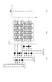
(寄与率生成方法)
次に、図10を用いて、ヘッドシェーディング補正に使用する寄与率について説明を行う。101は、記録媒体上に記録する画像データを表しており、102は4パス記録時の記録ヘッドの動きを示している。本図では、記録ヘッド102はシアンインク用のノズル列41Cのみを表しており、説明を簡単にするため、1つのノズル列が32ノズルである例を示している。1回の記録走査が終わる毎に副走査方向に8ノズル分ずつ記録媒体を搬送した際の位置関係を示しており、横線が記録走査の境界を示している。尚、矢印で示すように図の上が記録媒体の排紙方向(副走査方向)である。記録ヘッド102の32ノズルのうち2ノズルずつを1つのノズル群として16のグループに分割し、ノズル群毎に10C−1から10C−16までの番号で区別する。103は、2ノズル単位の各ノズル群に対応するマスクパターンの記録許容率を表したものであり、補完関係にある4領域を足し合わせると合計100%となっている。尚、記録ヘッド102のノズルとマスクパターンの位置関係は通常固定である。従って、4パス記録の各走査の間に、副走査方向に記録媒体が搬送されて画像データ101と記録ヘッド102の位置関係がずれると、画像データ101とマスクパターンの位置関係もずれることになる。
(Contribution rate generation method)
Next, the contribution rate used for the head shading correction will be described with reference to FIG.
尚、寄与率とは、画像データにおける各画像領域の記録に使用されるノズルの使用率を表したものである。従って、画像データと記録ヘッド(マスクパターン)との位置関係に応じて寄与率が変化する。例えば、寄与率が100%である場合、対応する画像データは寄与率が100%であるノズル群のみで記録されることを意味している。 The contribution rate represents the usage rate of the nozzles used for recording each image area in the image data. Therefore, the contribution rate changes according to the positional relationship between the image data and the recording head (mask pattern). For example, when the contribution rate is 100%, it means that the corresponding image data is recorded only by the nozzle group having the contribution rate of 100%.
図11のフローチャートを用いて、画像領域毎の寄与率テーブルの生成方法について説明する。前述したように、本フローは、記録装置が印刷ジョブを受信し、画像データが画像入力部502から画像出力部504に流れてきたタイミングで開始される。ステップS111において、印刷ジョブに含まれる記録条件を示す記録条件情報に基づいて、マスクデータの記録許容率112と画像データとの位置関係が決定する。そして決定した位置関係から、所定数のラスター分の記録に用いられるノズル群の寄与率を算出する。次に、ステップS113において、算出された寄与率が寄与率テーブル104に書き込まれる。ステップS114において、画像データの最後まで寄与率を算出する処理が終了したかを判断し、最後まで書き込んだ場合には処理を終了する。最後まで算出し終えていない場合は、ステップS111に戻り、次の所定数のラスター分の寄与率を算出する。
A method for generating a contribution rate table for each image area will be described with reference to the flowchart of FIG. As described above, this flow starts when the recording apparatus receives a print job and image data flows from the
生成された寄与率テーブルを用いて、図6のステップS605におけるヘッドシェーディング処理が行われ、その後、記録媒体への記録動作を開始する。尚、寄与率テーブルが生成された領域から順番にステップS605以降の処理を行ってもよい。全ての画像領域に対応する寄与率テーブルが生成される前に記録動作を開始することで、印刷ジョブが記録装置に送られてから記録動作が開始するまでのタイムラグを短くすることができる。寄与率テーブル104は、記録制御部507にあるROM509に書き込まれるが、RAM510や画像入力部にあるROM506であってもよい。また、寄与率テーブル104を予め記憶しておき、使用するパスマスクなどに応じて選択する方法でもよい。
Using the generated contribution rate table, the head shading process in step S605 in FIG. 6 is performed, and then the recording operation on the recording medium is started. In addition, you may perform the process after step S605 in an order from the area | region where the contribution rate table was produced | generated. By starting the recording operation before the contribution rate tables corresponding to all image regions are generated, the time lag from when the print job is sent to the recording apparatus until the recording operation starts can be shortened. The contribution rate table 104 is written in the ROM 509 in the
図10に戻り、寄与率テーブル104について説明する。寄与率テーブル104は、画像データのラスター毎に、ノズル群10C−1からノズル群10C−16までの各ノズル群を使用する比率が定められたテーブルである。例えば、画像データ上の画像領域105に対しては、ノズル群10C−4、ノズル群10C−8、ノズル群10C−12、ノズル群10C−16の4つのノズル群を用いて画像を記録する。従って、寄与率テーブルにおいて、上記4つのグループに対応する位置の寄与率は0よりも大きく、使用しないノズル群の寄与率は0となる。この寄与率テーブル104は、画像データと記録ヘッドのノズル列との位置関係に応じて決定する。尚、寄与率テーブル104の副走査方向における要素数は、画像データにおける副走査方向のサイズと同じである。ノズル群毎の寄与率の算出に用いる、マスクパターンの記録許容率は、マスクパターンにおける記録許容画素の数をカウントしてもよい。本実施形態では、予めマスクパターンに対応したテーブルとして、ノズル群のサイズに対応した記録許容率テーブルを格納している。
Returning to FIG. 10, the contribution rate table 104 will be described. The contribution rate table 104 is a table in which a ratio for using each nozzle group from the
尚、ヘッドシェーディング補正を行う単位は1以上のノズル群毎に行えばよいが、複数のラスター単位で補正を行っても効果があるため、処理速度と補正効果の観点から補正単位を決定すればよい。本実施形態では、2ノズル(2ラスター)単位で画像データを補正する。 The unit for performing head shading correction may be performed for each of one or more nozzle groups. However, since it is effective to perform correction in a plurality of raster units, if the correction unit is determined from the viewpoint of processing speed and correction effect. Good. In this embodiment, image data is corrected in units of 2 nozzles (2 rasters).
(ヘッドシェーディング補正)
図12を用いて、ヘッドシェーディング補正処理について説明する。本実施形態では、ノズル群毎の濃度値を基にノズル群毎に作成したHS補正用1次元LUT606と、寄与率テーブル104と、を用いて、画像データの濃度を補正する。画像データの単位領域を記録するために用いるノズル群毎の比率を示す情報である寄与率と、ノズル群の濃度比率と、の積を取得し、該単位領域の記録に用いる全てのノズル群の和をとったものが出力値となる。
(Head shading correction)
The head shading correction process will be described with reference to FIG. In the present embodiment, the density of the image data is corrected using the HS correction one-
図12(a)は、記録ヘッド102の濃度比率121と、ノズル群10C−1〜ノズル群10C−16の対応関係を示す図である。以下に、濃度比率121の算出方法を説明する。前述の図8の処理を実行することにより、各ノズル群の濃度値をもとに算出したHS補正用1次元LUT606を用いる。補正前の画像データの濃度値とHS補正用1次元LUT606を用いることで、ノズル群毎の補正後の濃度値が算出される。濃度比率121は、補正後の濃度値を補正前の濃度値で割った比率を示しており、数値が大きいほど補正前の濃度値がターゲット値よりも低いことを表している。
FIG. 12A is a diagram illustrating a correspondence relationship between the
図12(b)は、画像データ122と、4パス記録を行う際の記録ヘッド102のノズル群毎の濃度比率121と、の対応関係を示したものである。画像データ122は、シアンインク用のノズル列によって記録されるシアンの画像データであり、各画像領域に記載されている数値は、8bitの濃度値である。例えば、画像領域123に対して記録すべき画像データの濃度値は128である。そして、画像領域123での各ノズル群の寄与率は、ノズル群10C−4が16%、ノズル群10C−8が40%、ノズル群10C−12が34%、ノズル群10C−16が10%であり、他のノズル群は0%である。そして、ノズル群10C−4、ノズル群10C−8、ノズル群10C−12、ノズル群10C−16の濃度比率は、それぞれ104%、100%、100%、105%である。
FIG. 12B shows a correspondence relationship between the
濃度比率100%とは、画像データの濃度値が128である場合に、記録された画像の濃度が128となることを示している。従って、上記の濃度比率を有したノズル群を用いて画像領域123を記録する場合の計算値は下記の式によって算出される。
128×(1.04×0.16+1×0.40+1×0.34+1.05×0.10}≒129.5
本実施形態では、小数点以下を四捨五入し、画像領域123の補正後の濃度値は130となる。本実施形態では2ラスター単位で上述した処理を画像データ上の全領域に対して繰り返し実施することにより、ヘッドシェーディング補正が行われる。
A density ratio of 100% indicates that when the density value of the image data is 128, the density of the recorded image is 128. Therefore, the calculated value when the
128 × (1.04 × 0.16 + 1 × 0.40 + 1 × 0.34 + 1.05 × 0.10} ≈129.5
In this embodiment, the fractional part is rounded off, and the corrected density value of the
尚、図12(b)において、ノズル群10C−4が、1走査目に画像領域123を記録する際の濃度比率は104%であり、2走査目に画像領域124を記録する際の濃度比率121も104%である。尚、本実施形態では説明を簡単にするため、補正前の画像データの濃度値によらず、濃度比率121の値を一定に設定している。しかし、補正前の濃度値によってHS補正用1次元LUT606から導かれる補正後の濃度値が異なる場合には、記録ヘッドの濃度比率121を補正前の濃度値に応じて異ならせる必要がある。
In FIG. 12B, the density ratio when the
以上説明したHS補正を行うことで、記録媒体上の各画像領域の記録に用いるノズル群毎の使用率(寄与率)が、画像領域ごとに異なる場合に、寄与率を用いて補正後の濃度値を決定することで画像領域間の濃度ムラを低減することができる。このような構成により、ノズル毎の吐出量ばらつきに起因する画像領域間の濃度ムラを抑制することができる。 By performing the HS correction described above, when the usage rate (contribution rate) for each nozzle group used for recording each image area on the recording medium differs for each image area, the density after correction using the contribution rate By determining the value, density unevenness between image areas can be reduced. With such a configuration, it is possible to suppress density unevenness between image areas due to discharge amount variation for each nozzle.
尚、寄与率テーブルを予めROMに記憶しておくことも可能ではあるが、印刷ジョブを受信するたびに寄与率テーブルを生成する方が望ましい。各画像領域への記録に用いるノズル群が決まった後に寄与率テーブルを生成することにより、例えば記録媒体の中央部と端部のように副走査方向に異なる位置の領域において記録に使用されるノズル群の組み合わせが異なる場合であっても、適切に画像データを補正することができる。 Although it is possible to store the contribution rate table in the ROM in advance, it is preferable to generate the contribution rate table each time a print job is received. By generating a contribution ratio table after the nozzle group used for recording in each image area is determined, for example, nozzles used for recording in areas at different positions in the sub-scanning direction, such as the center and end of the recording medium Even when the group combination is different, the image data can be corrected appropriately.
具体的には、縁あり記録時の余白量や縁なし記録時の記録媒体に対する画像データのはみだし量は常に一定ではなく、ユーザ設定や画像データによって任意の値とすることができる。この余白量やはみだし量によって記録ヘッドと記録媒体との位置関係が異なるため、それに伴って各ノズル群の使用比率が異なる。このため、記録媒体上の画像領域に対して各ノズル群を記録に用いる比率(寄与率)は、印刷ジョブによって異なることが多い。従って、ROM59に寄与率テーブルを記憶しておくのではなく、印刷ジョブを受信する度に寄与率テーブルを生成することが好ましいのである。 Specifically, the margin amount at the time of margined recording and the amount of image data protruding to the recording medium at the time of marginless recording are not always constant, and can be set to arbitrary values according to user settings and image data. Since the positional relationship between the recording head and the recording medium varies depending on the amount of margin and the amount of protrusion, the usage ratio of each nozzle group varies accordingly. For this reason, the ratio (contribution rate) at which each nozzle group is used for recording with respect to the image area on the recording medium often differs depending on the print job. Therefore, it is preferable to generate the contribution rate table every time a print job is received, instead of storing the contribution rate table in the ROM 59.
(HS補正LUT生成タイミング判定方法)
次に、本発明の特徴構成である、画像データのドットカウント値からノズル群毎のドットカウント値を算出する処理について説明する。前述のヘッドシェーディング補正に用いるHS補正用一次元LUTの生成は、記録ヘッドの濃度ムラに変動が無ければ、ヘッドの使用初期に1回の補正を行えばよい。しかし、実際には、インクを吐出し続けることにより、記録ヘッドのノズル毎の吐出量や着弾位置が変動してしまい、ヘッドの使用初期には生じなかった濃度ムラが生じてしまう。そこで、ヘッドシェーディング補正の効果を高めるためには、インクの吐出回数による濃度ムラの変動ペースを考慮した上で、図8で説明したHS補正用一次元LUT606を生成するフローを実行し、LUTの値を更新する必要がある。
(HS correction LUT generation timing determination method)
Next, a process for calculating a dot count value for each nozzle group from a dot count value of image data, which is a characteristic configuration of the present invention, will be described. The generation of the HS correction one-dimensional LUT used for the head shading correction described above may be performed once in the initial use of the head if there is no variation in the density unevenness of the recording head. However, in practice, when ink is continuously ejected, the ejection amount and landing position of each nozzle of the recording head fluctuate, resulting in density unevenness that did not occur in the initial use of the head. Therefore, in order to enhance the head shading correction effect, the flow for generating the HS correction one-
本実施形態では、ノズル群毎に吐出したドット数をカウントしたドットカウント値を取得し、いずれかのノズル群において、カウント値が予め設定した閾値を超えた場合に、LUT更新のタイミングだと判断する。このとき、ノズル群毎のカウント値を取得する方法としては、プリンタ内に、インクを吐出した回数をノズル毎にカウントする機能を搭載する方法が考えられる。しかし、高密度化された記録ヘッドには、非常に多くのノズルが設けられているため、ノズル毎に吐出した数をカウントする方法では、カウントに必要となる制御回路やメモリのサイズが膨大になり、高コスト化や画像データ処理時間の増大などの弊害に繋がる。一方、画像データからドットカウントを行う方法では、ノズルの数に関係なく一定の負荷で処理することができ、実際に吐出されたドット数をノズル毎にカウントする方法に比べて簡易的である。しかしながら、画像データをドットカウントしただけでは、ノズル列全体でのドットカウント値がわかるだけで、各ノズル群がどのくらい吐出したのかを示す情報を得ることはできない。 In this embodiment, a dot count value obtained by counting the number of dots ejected for each nozzle group is acquired, and when the count value exceeds a preset threshold value in any nozzle group, it is determined that the timing for LUT update is reached. To do. At this time, as a method for acquiring the count value for each nozzle group, a method in which a function of counting the number of times ink is ejected for each nozzle is installed in the printer. However, since the recording head with a high density has a large number of nozzles, the method of counting the number of ejections for each nozzle requires enormous amounts of control circuitry and memory. This leads to adverse effects such as an increase in cost and an increase in image data processing time. On the other hand, the method of counting dots from image data can be processed with a constant load regardless of the number of nozzles, and is simpler than the method of counting the number of actually ejected dots for each nozzle. However, only by counting the dot of the image data, it is not possible to obtain information indicating how much each nozzle group has ejected, only by knowing the dot count value in the entire nozzle array.
そこで、本実施形態では、画像データのドットカウント値と前述したヘッドシェーディング補正において使用した寄与率とを用いて、ノズル群毎に吐出したドットのドットカウント値を取得し、補正タイミングを判定する。 Therefore, in the present embodiment, the dot count value of the dots ejected for each nozzle group is acquired using the dot count value of the image data and the contribution rate used in the head shading correction described above, and the correction timing is determined.
図16は、寄与率と画像データから算出したドットカウント値とから、各ノズル群のドットカウント値を取得する処理のフローチャートである。ステップS161において、画像データに基づいて、画像領域毎にドットカウント値を取得する。ステップS162において、ステップS161で取得した画像領域毎のドットカウント値に、寄与率テーブル104に基づいて取得した寄与率をかけることで、ノズル群毎のドットカウント値を算出する。ステップS162は、ステップS163において、画像データが終了したと判断されるまで繰り返される。ステップS164において、ノズル群毎に、画像データから算出したドットカウント値の合計をROM509に記憶する。ROM509には、それまでに記録された画像データのドットカウント値の累計値がノズル群毎に記憶されている。ステップS164で算出されたカウント値の合計を、記憶されている累計値に加算する。 FIG. 16 is a flowchart of processing for acquiring the dot count value of each nozzle group from the contribution rate and the dot count value calculated from the image data. In step S161, a dot count value is acquired for each image area based on the image data. In step S162, the dot count value for each nozzle group is calculated by multiplying the dot count value for each image area acquired in step S161 by the contribution rate acquired based on the contribution rate table 104. Step S162 is repeated until it is determined in step S163 that the image data has been completed. In step S164, the total dot count value calculated from the image data is stored in the ROM 509 for each nozzle group. The ROM 509 stores a cumulative value of dot count values of image data recorded so far for each nozzle group. The sum of the count values calculated in step S164 is added to the stored cumulative value.
上述したノズル群毎のドットカウント値の算出処理は、図11を用いて説明した寄与率の生成の後に行う必要があり、本実施形態においては寄与率の生成が画像データの最後まで完了した後に行う。尚、一部の寄与率が算出されたタイミングで処理を開始してもよく、寄与率の生成処理とノズル群毎のドットカウント値の算出処理を同時に進めながら画像を記録してもよい。また、画像データの記録動作が完了した後に行ってもよい。算出したドットカウント値は、寄与率テーブル104と同様にROM509に格納されるが、RAM510に格納してもよい。
The above-described dot count value calculation processing for each nozzle group needs to be performed after the generation of the contribution rate described with reference to FIG. 11. In this embodiment, after the generation of the contribution rate is completed to the end of the image data. Do. Note that the processing may be started at a timing when a part of the contribution rate is calculated, or an image may be recorded while the contribution rate generation processing and the dot count value calculation processing for each nozzle group are simultaneously performed. Alternatively, it may be performed after the image data recording operation is completed. The calculated dot count value is stored in the ROM 509 similarly to the contribution rate table 104, but may be stored in the
図13を用いて、図16で述べたノズル群毎のドットカウント値を算出する方法について詳しく説明する。画像データ131は、シアンインクで記録される画像データである。画像領域131a〜131hの内部に記載されている数値は、各画像領域からインク滴を吐出する回数を示すドットカウント値を表している。記録ヘッド102の4回の走査によって、画像領域131a〜131hに画像が記録される。例えば、画像領域131aでは、記録ヘッド102のノズル群10C−4、ノズル群10C−8、ノズル群10C−12、ノズル群10C−16からインクが吐出されて画像が完成する。寄与率テーブル132は、画像領域131a〜131hのそれぞれに対応する各ノズル群の寄与率が示されている。図10を用いて説明したように、各走査の記録許容率が異なるマスクパターン103を用いた場合の、画像領域131a〜131hでのノズル群10C−1〜ノズル群10C−16の寄与率である。尚、寄与率テーブル133は、画像領域131a〜131hに対して、各走査の記録許容率が均等なマスクパターンを用いた場合の寄与率を表している。
The method for calculating the dot count value for each nozzle group described in FIG. 16 will be described in detail with reference to FIG. The
ノズル群10C−4に着目し、ドットカウント値を算出する方法を具体的に説明する。寄与率テーブル132を用いた場合、ノズル群10C−4は、画像領域131aに対して、1000×0.16=160発を吐出し、画像領域131eに対して、2000×0.16=320発を吐出する。一方、4回の走査での記録許容率が均等であるマスクパターンに対応する寄与率テーブル133を用いた場合、ノズル群10C−4は、画像領域131aに対して1000×0.25=250発、画像領域131eに対して2000×0.25=500発を吐出する。すなわち、同じ画像データを記録したとしても、使用するマスクパターンによって各ノズル群から吐出されるドット数が異なる。また、同じマスクパターンを使用したとしても、記録する画像が異なると、ノズル群毎から吐出されるドット数が異なる。
Focusing on the
このように、画像データのドットカウントを行っただけでは、ノズル列毎に吐出されたドット数を示すカウント値の合計を得ることができるものの、ノズル群毎にドットカウント値を取得することができない。また、1列のノズル列で吐出されたカウント値の合計が同じ値であっても、異なるマスクパターンを使用した場合や、画像データによるノズル群毎のドットカウント値の変動を考慮することができない。従って、画像データの単位領域毎のドットカウント値と、その画像を記録するために各ノズル群を用いる比率である寄与率を用いることで、実際にインク滴を吐出した回数をカウントする構成を用いずに、ノズル群毎のドットカウント値を算出することができる。 As described above, the dot count value cannot be acquired for each nozzle group although the total count value indicating the number of dots ejected for each nozzle row can be obtained by only performing the dot count of the image data. . Further, even if the total count values ejected from one nozzle row are the same, it is not possible to consider the case where different mask patterns are used or the variation in the dot count value for each nozzle group due to image data. . Therefore, a configuration is used that counts the number of times ink droplets are actually ejected by using a dot count value for each unit area of the image data and a contribution ratio that is a ratio of using each nozzle group to record the image. Instead, the dot count value for each nozzle group can be calculated.
図14(a)は、HS補正用一次元LUTの生成する必要性があるかどうかを判定する方法を示す図である。ここでは、図16のフローにより算出したノズル群毎のドットカウント値の累計値と、閾値を用いた場合について、図14(a)に示したフローを用いて具体的に説明する。本実施形態では、テストパターンの印刷及び測色を行わずに、補正用一次元LUTを更新する必要があるかどうかを内部的に判定することができる。判定処理は、電源ONとなった時、記録ヘッドの交換が終了した時、記録媒体を装置にセットした時、印刷ジョブが終了した時、1ページの印刷終了時などに行われる。 FIG. 14A is a diagram illustrating a method for determining whether it is necessary to generate an HS correction one-dimensional LUT. Here, the case where the cumulative value of the dot count value for each nozzle group calculated by the flow of FIG. 16 and the threshold value are used will be specifically described using the flow shown in FIG. In this embodiment, it is possible to internally determine whether or not the correction one-dimensional LUT needs to be updated without printing the test pattern and performing colorimetry. The determination process is performed when the power is turned on, when the replacement of the recording head is completed, when the recording medium is set in the apparatus, when the print job is completed, when one page is printed.
まず、ステップS141において、前回、HS補正用一次元LUT606の更新を行ったタイミングで取得した累計値を取得する。次に、ステップS142において、図16のステップS164においてROM509に格納された、ノズル群毎のドットカウント値の累計値との差分を取得する。これは、前回のLUT更新時以降に、各ノズル群から吐出されたインク滴の数に相当し、累計値の増加数である。記録ヘッドが交換された後、記録装置に現在搭載されている記録ヘッドでのHS補正用一次元LUT606を更新した履歴が無い場合には、記録ヘッド交換後からのドットカウント値の合計を、累計の増加数として取得する。
First, in step S141, the cumulative value acquired at the timing when the HS correction one-
ステップS143において、取得した増加数と予め設定した閾値を比較する。本実施形態では、各ノズル群のドットカウント値の増加数のうちの最大値と閾値とを比較する。閾値を超えている場合には、ステップS144に進み、補正の必要性があると判定する。閾値を超えていない場合には、ステップS145に進み、補正の必要性はなしと判定する。補正の必要性があると判定された場合、ステップS146において、HS補正用一次元LUT606を更新する必要性があることを示す情報を記録装置のオペレーションパネル上に表示し、ユーザに通知する。
In step S143, the acquired increase number is compared with a preset threshold value. In the present embodiment, the maximum value of the increased number of dot count values of each nozzle group is compared with a threshold value. If it exceeds the threshold, the process proceeds to step S144, and it is determined that there is a need for correction. If the threshold is not exceeded, the process proceeds to step S145, and it is determined that there is no need for correction. If it is determined that there is a need for correction, in step S146, information indicating that it is necessary to update the HS correction one-
図14(b)は、オペレーションパネル上に表示する画面の模式図であり、ヘッドシェーディングの必要性が有ることをユーザに通知している。この通知を受けたユーザは、ヘッドシェーディングの実行を実施するか否かを自らで判断することができる。尚、このような通知と一緒に、ユーザがヘッドシェーディングの実行を指示するための実行ボタンを表示する形態であってもよい。 FIG. 14B is a schematic diagram of a screen displayed on the operation panel, and notifies the user that there is a need for head shading. The user who has received this notification can determine by himself whether or not to execute the head shading. In addition, the form which displays the execution button for a user to instruct | indicate execution of head shading with such a notification may be sufficient.
以上のように、本実施形態では、記録媒体上の単位領域を記録するために複数のノズル群毎(記録素子群毎)をそれぞれ用いる比率(寄与率)を取得し、寄与率テーブルを生成する。そして、画像データのドット数と寄与率とから、ノズル群毎に記録すべきドットカウント値を取得し、ドットカウント値をROM509に記憶する。そして、記憶されたドットカウント値に基づいて、HS補正用一次元LUT606を新たに生成して更新する必要があるかどうかを判定する。これにより、各ノズルから吐出されたドットの数を直接カウントする方法に比べて簡易な構成でノズル群毎のドットカウント値を取得することができ、ヘッドシェーディング補正に用いる濃度補正データの生成タイミングを高精度に判定することができる。
As described above, in this embodiment, a ratio (contribution rate) that uses each of a plurality of nozzle groups (each recording element group) to record a unit area on a recording medium is acquired, and a contribution rate table is generated. . Then, the dot count value to be recorded for each nozzle group is acquired from the number of dots of the image data and the contribution rate, and the dot count value is stored in the ROM 509. Then, based on the stored dot count value, it is determined whether it is necessary to newly generate and update the HS correction one-
尚、ROM509に記憶するドットカウント値は、画像を記録する毎にカウントした値を全て記憶しておいてもよく、累計値だけを記憶しておいてもよい。このとき、HS補正用一次元LUT606を更新する必要性を判断するためには、前回生成されたタイミングからの増加数が取得できるようにする必要がある。上記実施形態では、前回生成されたタイミングでの累計値を記憶しておき、現在の累計値との差分を増加数として取得した。この他、前回生成されたタイミングで累計値をリセットすることで、現在記憶されている累計値を前回からの増加数として取得する方法でも構わない。
The dot count value stored in the ROM 509 may store all the values counted every time an image is recorded, or may store only the cumulative value. At this time, in order to determine the necessity of updating the one-
尚、ステップS143において、ノズル群毎のドットカウント値の増加数の最大値と閾値とを比較し、いずれかのノズル群で増加数が閾値を超えた場合にLUT更新の必要があると判定したが、他の判定方法であってもよい。例えば、各ノズル群のドットカウント値の増加数の最大値と最小値を取得し、取得した最大値と最小値の差分を閾値と比較することによって判定を行ってもよい。これにより、ノズル群の使用頻度の違いによって濃度が一定以上開かないうちに補正タイミングを判断することができる。また、ノズル列中央部の寄与率が高い場合には、ノズル列端部の吐出量変動よりも中央部の吐出量変動の方が濃度ムラの発生に対する影響が大きい。このため、ノズル群の位置によって係数をかけ、傾斜をつけてから差分をとることで、より適切なタイミングで判定することができる。また、所定数以上のノズル群の増加数が閾値を超えた場合や、増加数が閾値を超えたノズル群が存在するインク色が所定数以上であった場合にHS補正用一次元LUT606を更新する必要があると判定してもよい。また、全てのインク色において閾値を超えたノズル群が存在した場合にHS補正用一次元LUT606を更新する必要があると判定してもよい。このとき、閾値をインク色によって異ならせてもよく、濃度ムラが出やすいインクや濃度ムラが視認されやすいインクほど閾値を小さくすることが好ましい。
In step S143, the maximum value of the dot count value increase for each nozzle group is compared with a threshold value, and it is determined that the LUT needs to be updated when the increase number exceeds the threshold value for any nozzle group. However, other determination methods may be used. For example, the determination may be performed by acquiring the maximum value and the minimum value of the increase number of the dot count value of each nozzle group, and comparing the difference between the acquired maximum value and the minimum value with a threshold value. As a result, the correction timing can be determined before the density opens above a certain level due to the difference in the usage frequency of the nozzle groups. Further, when the contribution ratio of the central portion of the nozzle row is high, the variation in the discharge amount at the central portion has a greater influence on the occurrence of density unevenness than the change in the discharge amount at the end portion of the nozzle row. For this reason, it is possible to determine at a more appropriate timing by multiplying the coefficient by the position of the nozzle group and taking the difference after applying the inclination. Also, the HS correction one-
尚、寄与率は、主走査方向には1つ設定され、副走査方向には任意のサイズで複数設定することが可能であるが、バンド幅に収まるほうが好ましく、ヘッドシェーディング補正単位と同じサイズであるとより望ましい。また、ヘッドシェーディング補正で用いた寄与率テーブルでのノズル群のサイズと、ドットカウント値算出に用いた寄与率テーブルでのノズル群のサイズが異なっていてもよい。 Note that one contribution rate can be set in the main scanning direction and a plurality of arbitrary sizes can be set in the sub-scanning direction. However, it is preferable that the contribution ratio is within the bandwidth, and the same size as the head shading correction unit. More desirable. Further, the size of the nozzle group in the contribution rate table used for the head shading correction may be different from the size of the nozzle group in the contribution rate table used for calculating the dot count value.
本実施形態では、ノズル群毎の寄与率をもとにヘッドシェーディング補正を行い、この寄与率を用いてノズル群毎のドットカウント値を算出したが、必ずしもヘッドシェーディング補正に寄与率を用いなくてもよい。ヘッドシェーディング補正に寄与率を用いずとも、画像データのドットカウント値と寄与率を用いて各ノズル群のドットカウント値を求めることにより、ヘッドシェーディング補正のタイミングを判定することができる。 In this embodiment, head shading correction is performed based on the contribution rate for each nozzle group, and the dot count value for each nozzle group is calculated using this contribution rate. However, the contribution rate is not necessarily used for head shading correction. Also good. Even if the contribution rate is not used for the head shading correction, the timing of the head shading correction can be determined by obtaining the dot count value of each nozzle group using the dot count value of the image data and the contribution rate.
また、本実施形態では2値の画像データのドットカウント値と2値のマスクデータから算出した寄与率を用いたが、それぞれ多値のデータであってもよい。多値データとドットカウント値の対応関係さえ決めておけば、対応は可能である。 In this embodiment, the contribution rate calculated from the dot count value of the binary image data and the binary mask data is used, but multivalued data may be used. If the correspondence between the multi-value data and the dot count value is determined, the correspondence is possible.
また、本実施形態ではヘッドシェーディングの補正単位と同様に、ドットカウント値を算出する際も2ノズル毎のノズル群としているが、ノズル群のサイズはこの限りではない。ノズル群は1ノズルでもよく、2ノズルよりも大きな値でも良い。ノズル群のサイズによって、ノズル群毎のドットカウント値を算出する負荷は調節することが可能であり、本実施形態を用いることで、ドットカウント値の精度とドットカウント値算出速度のバランスを変えることが可能であるといえる。 Further, in the present embodiment, similarly to the head shading correction unit, the nozzle group for every two nozzles is used when calculating the dot count value, but the size of the nozzle group is not limited to this. The nozzle group may be one nozzle or a value larger than two nozzles. The load for calculating the dot count value for each nozzle group can be adjusted according to the size of the nozzle group. By using this embodiment, the balance between the dot count value accuracy and the dot count value calculation speed can be changed. Can be said to be possible.
また、本実施形態では、ノズル群毎の記録特性情報として濃度値を記憶する例について説明したが、ノズル群毎のパッチの測定結果やノズル群毎のHS補正用LUTを記録特性情報として記憶する形態であってもよい。 In this embodiment, an example in which density values are stored as recording characteristic information for each nozzle group has been described. However, patch measurement results for each nozzle group and HS correction LUTs for each nozzle group are stored as recording characteristic information. Form may be sufficient.
(第2の実施形態)
前述の実施形態では、テストパターンの測定結果に基づいてノズル群毎のHS補正用一次元LUT606を生成し、ROM509に記憶する形態について説明した。本実施形態では、テストパターンの測定結果をROM509に記憶し、記録装置が印刷ジョブを受信してから画像領域毎のHS補正データを生成する方法について説明する。
(Second Embodiment)
In the above-described embodiment, the mode in which the HS correction one-
図8のフローチャートにおいて、ステップS801〜ステップS808までの処理は大1の実施形態と同様である。本実施形態では、ステップS808においてパッチを測定した測定結果をROM509に保存した後、ステップS809のHS補正LUT生成を行わずにステップS809に進み、記録媒体を排紙してフローを終了する。ROM509には、複数濃度のパッチの測定結果がノズル群毎に記憶される。 In the flowchart of FIG. 8, the processing from step S801 to step S808 is the same as that of the first embodiment. In the present embodiment, after the measurement result obtained by measuring the patch in step S808 is stored in the ROM 509, the flow proceeds to step S809 without generating the HS correction LUT in step S809, and the recording medium is discharged and the flow ends. The ROM 509 stores the measurement results of the multiple density patches for each nozzle group.
そして、記録装置が印刷ジョブを受信すると、図11に示したフローチャートに沿って寄与率テーブルが生成される。生成した寄与率テーブルとROM509に記憶されたノズル群毎の測定結果とに基づいて、画像領域毎にHS補正用1次元LUT606が生成される。そして、生成されたHS補正用1次元LUT606を用いて各画像領域の多値の画像データを補正し、補正されたデータに従って画像が記録される。
When the printing apparatus receives the print job, a contribution rate table is generated according to the flowchart shown in FIG. An HS correction one-
このような方法を用いることにより、HS補正LUTを記憶する場合に比べてROM509の容量を削減し、簡易な構成でヘッドシェーディング補正処理を行うことができる。また、第1の実施形態では、画像データの値によらず濃度比率の値として一定値を用いる形態で説明したが、本実施形態の方法であれば画像領域毎のHS補正1次元LUTが生成されるため、濃度値に応じて適切に補正を行うことができる。 By using such a method, the capacity of the ROM 509 can be reduced as compared with the case where the HS correction LUT is stored, and the head shading correction process can be performed with a simple configuration. In the first embodiment, the constant value is used as the density ratio value regardless of the image data value. However, with the method according to the present embodiment, an HS correction one-dimensional LUT is generated for each image area. Therefore, it is possible to appropriately perform correction according to the density value.
(第3の実施形態)
前述の実施形態においては、画像データのドットカウント値と寄与率を用いてHS補正用一次元LUT606を生成するタイミングを判定した。本実施形態では、画像データのドットカウント値ではなく、記録ヘッドのノズル列のドットカウント値をタイミングの判定に用いる例について説明する。
(Third embodiment)
In the above-described embodiment, the timing for generating the HS correction one-
図15は、記録ヘッド102におけるドットカウント値152a〜eを図示したものである。ノズル列毎に何発吐出したのかはノズル群毎に吐出カウントを行うのと比べると容易であり、プリンタへの処理負荷も小さい。
FIG. 15 illustrates the dot count values 152 a to 152 e in the
画像データ151は、副走査方向において16ノズル分のサイズの画像データである。152a〜eは、画像データ151を記録媒体上に記録するために、4パス記録の各走査で記録ヘッド102から吐出されるシアンインクのドットカウント値を表している。図で示した5回の走査において、記録ヘッドから吐出されるドットカウント値152a〜eを足し合わせると、画像データ151を記録する必要なインクの吐出数を算出することができる。すなわち、画像データ151を記録するために、1000+1500+800+4000+200=7500発のインクドットが吐出される。
The
ここで、ノズル群10C−4に着目すると、寄与率テーブル132にあるように、5階の走査のうち、1回目の走査と2回目の走査で、それぞれ寄与率16%で記録する。ノズル群10C−4が2回の走査で吐出したドットのドットカウント値は1000×0.16+1500×0.16=400と算出することができる。つまりノズル群10C−4は画像データ151を記録する際に、400発のドットを吐出したと予想される。
Here, paying attention to the
上記方法でノズル群毎にドットカウント値を取得し、第1の実施形態の図16を用いて説明したように、ノズル群毎のドットカウント値の累計値に加算していけばよい。そして、図14を用いて説明した判定フローと同様に、HS補正用一次元LUT606の生成(更新)を行うタイミングを判定すればよい。
The dot count value is acquired for each nozzle group by the above method, and as described with reference to FIG. 16 of the first embodiment, the dot count value may be added to the cumulative value of the dot count values for each nozzle group. Similar to the determination flow described with reference to FIG. 14, the timing for generating (updating) the HS correction one-
このように、ノズル列毎のカウント値を取得し、取得したカウント値と寄与率とからノズル群毎のドットカウント値を取得することができる。 In this way, the count value for each nozzle row is acquired, and the dot count value for each nozzle group can be acquired from the acquired count value and contribution rate.
(第4の実施形態)
本実施形態では、ヘッドシェーディング補正に用いるLUT生成のタイミングではなく、カラーキャリブレーションにおけるLUT生成のタイミングを判定する場合について説明する。カラーキャリブレーションとは、記録ヘッドによって記録される画像の色の変動を抑制し、常に安定状態のプリンタとして想定される基準色(ターゲット色)を記録するために行う色補正処理である。ヘッドシェーディング補正と同様に、記録媒体上に測定用カラーパッチを含むテストパターンを出力し、それを測定することで記録ヘッドにより記録される画像の色に関する情報を取得する。そして、取得した情報をもとに、基準色が記録されるように画像データに補正処理を行うことで、色変動を抑制することができる。ノズル群毎の濃度値が必要なヘッドシェーディングとは異なり、カラーキャリブレーションでは、ノズル列単位で一つの濃度値を取得して補正に用いる。ヘッドシェーディング補正と本実施形態におけるカラーキャリブレーションは、画像データをラスター方向に同一の補正値で補正するという観点では同じである。カラーキャリブレーションは、ノズル群毎ではなく、インク色毎に補正LUTが用意される。
(Fourth embodiment)
In the present embodiment, a case will be described in which the LUT generation timing in color calibration is determined instead of the LUT generation timing used for head shading correction. Color calibration is color correction processing that is performed in order to record a reference color (target color) that is assumed to be a stable printer at all times, while suppressing variations in the color of an image recorded by the recording head. Similar to the head shading correction, a test pattern including a measurement color patch is output on a recording medium, and information on the color of an image recorded by the recording head is obtained by measuring the test pattern. Then, based on the acquired information, the color variation can be suppressed by performing correction processing on the image data so that the reference color is recorded. Unlike head shading, which requires a density value for each nozzle group, in color calibration, one density value is acquired for each nozzle row and used for correction. Head shading correction and color calibration in the present embodiment are the same from the viewpoint of correcting image data with the same correction value in the raster direction. For color calibration, a correction LUT is prepared for each ink color, not for each nozzle group.
カラーキャリブレーションは、インク色毎に1つの濃度値を用いて補正を行うため、ノズル列全体でのドットカウント値に対する濃度値の変動がわかれば、ノズル群毎のドットカウント値がなくとも、LUT生成タイミングが判定可能である。例えば、判定に用いる閾値を、いずれかの印字モードで記録したパッチの濃度値の変動から設定すればよい。印字モード毎のマスクパターンの記録許容率の分布に違いがなければ充分な精度でLUT生成タイミングが判断できる。しかし、印字モードによって記録許容率の分布が大きく異なっている場合には、実行する印字モードによって判断するタイミングがばらついてしまう。 Since the color calibration is performed using one density value for each ink color, if the fluctuation of the density value with respect to the dot count value in the entire nozzle array is known, even if there is no dot count value for each nozzle group, the LUT The generation timing can be determined. For example, the threshold value used for the determination may be set from the change in the density value of the patch recorded in any printing mode. If there is no difference in the distribution of the mask pattern recording allowance for each printing mode, the LUT generation timing can be determined with sufficient accuracy. However, when the distribution of the recording allowance varies greatly depending on the print mode, the timing for determination varies depending on the print mode to be executed.
図17を用いて、マスクパターンの記録許容率の分布の違いによる補正タイミングのばらつきについて説明を行う。図17は、図13と同様に記録ヘッド102を用いた4パス記録であり、画像データ171を記録する。画像データ171は、シアンインクで記録される画像データであり、記載されている数値はぞれぞれの画像領域171a〜hにおけるドットカウント値である。画像データ171は、記録ヘッド102を用いて画像領域171a〜h毎に4回の走査を行うことで記録される。例えば、画像領域171aでは、記録ヘッド102のノズル群10C−4、ノズル群10C−8、ノズル群10C−12、ノズル群10C−16によってインクが吐出され、画像が完成する。画像領域171a〜h毎に対応するノズル群の寄与率は、寄与率テーブル172で示されている。寄与率テーブル172は、4回の走査のうち前半の2回の走査で記録が完成することを特徴としたマスクパターンを用いた場合の、画像領域171a〜hでのノズル群10C−1〜ノズル群10C−16の寄与率を表している。具体的には、ノズル群10C−1からノズル群10C−8はいずれかの画像領域で50%という値が入っているが、ノズル群10C−9からノズル群10C−16ではいずれの画像領域も0%しか入っていない。すなわち、前半の2回の走査で、画像データ171の記録が完了することを意味している。寄与率に対応するマスクパターンの記録許容率で説明すると、前半2回の走査が50%であり、後半2回の走査が0%となっている。
With reference to FIG. 17, the variation in correction timing due to the difference in the distribution of the mask pattern recording allowance will be described. FIG. 17 shows four-pass recording using the
一方、寄与率テーブル173は、各走査での記録許容率が均等なマスクパターンを画像領域171a〜hに用いた場合の寄与率を表しており、走査毎に25%で記録する。ノズル群10C−4に着目すると、画像データ151を寄与率50%の2回の走査で記録する。前述した計算式を用いて、ノズル群10C−4が2回の走査で吐出したドットのカウント値は1000×0.5+2000×0.5=1500と算出できる。つまり、画像データ171の記録に際し、ノズル群10C−4は1500発のドットを吐出したことがわかる。一方、マスクパターンの記録許容率が各走査25%ずつである場合、ノズル群10C−4が記録を終えるまでに吐出するドットのカウント値は1000×0.25+2000×0.25=750と算出できる。記録許容率の分布の違いによって、同じ画像データ171を記録したにも関わらず、ノズル群毎に吐出したドットのカウント値は大きく異なる。
On the other hand, the contribution rate table 173 represents the contribution rate when a mask pattern having a uniform print allowance rate in each scan is used for the
このように、LUT生成の必要性を判定する際には、図14を用いて説明したように、ドットカウント値と閾値を比較して判定すればよい。なお、ステップS143において用いられる閾値は、ヘッドシェーディングとカラーキャリブレーションとで異なる。HS補正用LUT生成の判定とカラーキャリブレーションのタイミングの判定を並行して行い、どちらかの判定で補正を必要があると判定されると、ユーザに補正を行う必要がある旨を通知してもよい。 As described above, when determining the necessity of LUT generation, as described with reference to FIG. 14, the dot count value and the threshold value may be compared for determination. Note that the threshold used in step S143 differs between head shading and color calibration. The HS correction LUT generation determination and the color calibration timing determination are performed in parallel, and if it is determined that correction is necessary in either determination, the user is notified that correction is necessary. Also good.
以上説明したように、カラーキャリブレーションのタイミング判定において、ノズル列のドットカウント値と閾値を比較した場合、印字モードによって使用するマスクパターンの記録許容率に違いがあると、判定タイミングにずれが生じる。しかし、カラーキャリブレーションのタイミング判定においても、前述の実施形態で述べてきた画像データのドットカウント値もしくはノズル列のドットカウント値と、寄与率を用いることで、適切な判定を行うことが可能となる。例えば、記録許容率の分布が均等なマスクパターンを用いて印字を行ったときの濃度変動をもとに閾値を設定しておき、ノズル群のいずれかが閾値を超えた場合にタイミング判定を行うようにすればタイミング判定の精度は向上する。 As described above, in the color calibration timing determination, when the dot count value of the nozzle row and the threshold value are compared, if there is a difference in the mask pattern recording allowance depending on the print mode, the determination timing is shifted. . However, even in the color calibration timing determination, it is possible to make an appropriate determination by using the dot count value of the image data or the dot count value of the nozzle array and the contribution rate described in the above embodiment. Become. For example, a threshold value is set based on density fluctuations when printing is performed using a mask pattern with an even distribution of recording allowance rates, and timing determination is performed when any of the nozzle groups exceeds the threshold value. By doing so, the accuracy of timing determination is improved.
(その他の実施形態)
前述した実施形態において、補正用データの更新が必要なタイミングを判定した判定結果をユーザに通知する方法としては、上記方法に限られるものではない。例えば、記録装置のオペレーションパネル上に通知する、ドライバ画面上に示す、ネットワークを通じてメールで通知する、といった構成にしても構わない。また、ユーザに通知するタイミングは画像記録終了後に限るものではなく、例えば印刷ジョブの途中に通知する形態であってもよい。また、補正用データ更新の必要性を画像データ各色において行い、いずれかの色で更新する必要がある場合に通知してもよいし、重要でないとみなした色に関しては通知しなくてもよい。
(Other embodiments)
In the embodiment described above, the method of notifying the user of the determination result of determining the timing at which correction data needs to be updated is not limited to the above method. For example, a configuration may be adopted in which notification is made on the operation panel of the recording apparatus, notification is made on the driver screen, and notification is made by mail via a network. In addition, the timing for notifying the user is not limited to after the end of image recording, and may be in the form of notification in the middle of a print job, for example. Further, the necessity of updating the correction data may be performed for each color of the image data, and notification may be made when it is necessary to update with any of the colors, or notification may not be made for colors deemed insignificant.
また、補正用データ更新の必要が有ると判定した場合、自動的にテストパターンを印刷および測定し、補正データの生成及び更新を行ってもよい。その際、自動で更新したことをユーザに通知することが望ましい。 If it is determined that the correction data needs to be updated, the test pattern may be automatically printed and measured to generate and update the correction data. At that time, it is desirable to notify the user of the automatic update.
また、前述の実施形態では、複数回の走査の間に記録媒体を搬送して画像を記録する所謂マルチパス記録の例で説明したが、複数のノズル列を備える記録ヘッドを用いて1回の走査で画像を記録する、所謂フルライン記録においても本発明を適用できる。また、前述の実施形態では、1色のインクにつき1列のノズル列を備える記録ヘッドを用いる例を示したが、1色につき複数列のノズル列を備える記録ヘッドを用いてもよい。尚、本発明は、記録ヘッドと記録媒体上の単位領域との複数回の相対走査によって画像を記録する場合に、各相対走査に用いる比率を寄与率として算出する。この複数回の相対走査は、必ずしも記録ヘッドもしくは記録媒体を複数回走査させるものに限らない。例えば、複数のノズル列を備えた記録ヘッドと記録媒体との1回の走査で画像を記録する場合には、各ノズル列のノズル群と記録媒体との相対走査を1回として、複数のノズル列を備えた記録ヘッドの1回の走査であっても複数回の相対走査とみなして構わない。 In the above-described embodiment, an example of so-called multi-pass printing in which a printing medium is conveyed during a plurality of scans to record an image has been described. However, a single recording head having a plurality of nozzle arrays is used for one time. The present invention can also be applied to so-called full line recording in which an image is recorded by scanning. In the above-described embodiment, an example in which a recording head having one nozzle row for each color of ink is used, but a recording head having a plurality of nozzle rows for each color may be used. In the present invention, when an image is recorded by a plurality of relative scans of the print head and the unit area on the print medium, a ratio used for each relative scan is calculated as a contribution rate. The plurality of relative scans are not necessarily limited to scanning the recording head or the recording medium a plurality of times. For example, when an image is recorded by a single scan of a print head having a plurality of nozzle rows and a print medium, the nozzle group of each nozzle row and the print medium are set as a single scan, and the plurality of nozzles Even a single scan of a recording head having a row may be regarded as a plurality of relative scans.
また、本発明は、紙や布、不織布、OHPフイルム等の記録媒体を用いる記録装置全てに適用が可能であり、具体的な適用装置としては、プリンタ、複写機、ファクシミリなどの事務機や大量生産機等を挙げることができる。 Further, the present invention can be applied to all recording apparatuses using recording media such as paper, cloth, non-woven fabric, and OHP film. Specific application apparatuses include office machines such as printers, copiers, and facsimiles, and large quantities. Examples include production machines.
また、前述の実施形態では、本発明の特徴的な処理を行う記録制御部507がインクジェット記録装置内部に備えられている形態について説明したが、記録制御部507はインクジェット記録装置内部に備えられている必要はない。例えば、インクジェット記録装置と接続されるホストコンピュータ(画像入力部502)のプリンタドライバに上記記録制御部507の機能を持たせるようにしてもよい。この場合、プリンタドライバが、アプリケーションから受け取った多値の入力画像データに基づいて2値画像データを生成し、これを記録装置に供給することになる。このように、ホストコンピュ−タとインクジェット記録装置を含んで構成されるインクジェット記録システムも本発明の範疇である。この場合、ホストコンピュータは、インクジェット記録装置にデータを供給するデータ供給装置として機能し、また、インクジェット記録装置を制御する制御装置としても機能することになる。
In the above-described embodiment, the
また、本発明の特徴は、記録制御部507にて実行されるデータ処理にある。従って、本発明の特徴的なデータ処理を行う記録制御部507を備えたデータ生成装置も本発明の範疇である。記録制御部507がインクジェット記録装置に備えられている場合、このインクジェット記録装置が本発明のデータ生成装置として機能し、記録制御部507がホストコンピュ−タに備えられている場合、このホストが本発明のデータ生成装置として機能する。
A feature of the present invention is data processing executed by the
また、前述した第1乃至第4の実施形態は、記録材としてインクを吐出するための発熱素子が設けられたインクジェット記録ヘッドを例として説明したが、本発明はインクジェット記録ヘッドに限るものではない。インク以外の記録材を用いる記録素子を備える記録ヘッドを用いて画像を記録する場合であっても、本発明を適用することで記録素子列の副走査方向における記録濃度のばらつきを低減することができる。 In the first to fourth embodiments described above, the ink jet recording head provided with a heat generating element for ejecting ink as a recording material has been described as an example. However, the present invention is not limited to the ink jet recording head. . Even when an image is recorded using a recording head including a recording element that uses a recording material other than ink, variation in recording density in the sub-scanning direction of the recording element array can be reduced by applying the present invention. it can.
更に、上述した特徴的なデータ処理をコンピュータに実行させるコンピュータプログラムや、そのプログラムをコンピュータにより読み出し可能に格納した記憶媒体も本発明の範疇である。 Furthermore, a computer program that causes a computer to execute the characteristic data processing described above and a storage medium that stores the program so as to be readable by the computer are also within the scope of the present invention.
41 記録ヘッド
507 記録制御部
605 ヘッドシェーディング補正処理
606 HS補正用一次元LUT
104 寄与率テーブル
111 濃度比率
121a〜h 画像データのドットカウント値
133 判定値算出手段
41
104 Contribution ratio table 111 Density ratio 121a to h Dot count value of
Claims (15)
前記画像に対応するドットの数を示す第1ドットカウント値を取得する第1取得手段と、
前記複数の記録素子群に対応し、前記画像の記録のために前記複数の記録素子群それぞれを使用する比率に対応する複数の寄与率を取得する第2取得手段と、
前記第1ドットカウント値と前記複数の寄与率に基づいて、前記複数の記録素子群それぞれにおける複数の第2ドットカウント値を取得する第3取得手段と、前記複数の第2ドットカウント値に基づいて、前記画像データを補正するための濃度補正データを生成する必要があるかどうかを判定する判定手段と、
を備えることを特徴とする画像処理装置。 A unit area on the recording medium is formed by a plurality of recording element groups each configured by scanning at least one of a recording head having a plurality of recording elements and a recording medium a plurality of times, and each of the recording elements being part of the recording head. An image processing apparatus for processing image data corresponding to an image to be recorded in the unit area,
First acquisition means for acquiring a first dot count value indicating the number of dots corresponding to the image;
A second acquisition unit that corresponds to the plurality of recording element groups and acquires a plurality of contribution rates corresponding to a ratio of using each of the plurality of recording element groups for recording the image;
Based on the first dot count value and the plurality of contribution rates, third acquisition means for acquiring a plurality of second dot count values in each of the plurality of recording element groups, and on the basis of the plurality of second dot count values Determining means for determining whether it is necessary to generate density correction data for correcting the image data;
An image processing apparatus comprising:
前記判定手段は、前記第2ドットカウント値の合計に基づいて前記濃度補正データを生成する必要があるかどうかを判定することを特徴とする請求項1から3のいずれか1項に記載の画像処理装置。 The determination unit further includes a fourth acquisition unit that acquires, for each recording element group, the total of the second dot count values since the density correction data was acquired after the previous generation timing;
4. The image according to claim 1, wherein the determination unit determines whether the density correction data needs to be generated based on a sum of the second dot count values. 5. Processing equipment.
前記画像に対応するドットの数を示す第1ドットカウント値を取得する第1取得手段と、
前記複数の記録素子群に対応し、前記画像の記録のために前記複数の記録素子群それぞれを使用する比率に対応する複数の寄与率を取得する第2取得手段と、
前記第1ドットカウント値と前記複数の寄与率に基づいて、前記複数の記録素子群それぞれにおける複数の第2ドットカウント値を取得する第3取得手段と、
前記複数の第2ドットカウント値に基づいて、前記画像データを補正するための濃度補正データの生成の要否をユーザが決定するための表示を表示手段に表示させるかどうかを判定する判定手段と、
を備えることを特徴とする画像処理装置。 A unit area on the recording medium is formed by a plurality of recording element groups each configured by scanning at least one of a recording head having a plurality of recording elements and a recording medium a plurality of times, and each of the recording elements being part of the recording head. An image processing apparatus for processing image data corresponding to an image to be recorded in the unit area,
First acquisition means for acquiring a first dot count value indicating the number of dots corresponding to the image;
A second acquisition unit that corresponds to the plurality of recording element groups and acquires a plurality of contribution rates corresponding to a ratio of using each of the plurality of recording element groups for recording the image;
Third acquisition means for acquiring a plurality of second dot count values in each of the plurality of recording element groups based on the first dot count value and the plurality of contribution rates;
Determining means for determining whether or not to display on the display means a display for the user to determine whether or not to generate density correction data for correcting the image data based on the plurality of second dot count values; ,
An image processing apparatus comprising:
前記複数回の相対走査は、前記記録媒体上の前記単位領域に対する前記複数の記録素子列それぞれの記録に対応することを特徴とする請求項1から11のいずれか1項に記載の画像処理装置。 The recording head includes a plurality of recording element arrays corresponding to recording materials of the same color, and the image is recorded by one transport of the recording medium to the recording head,
12. The image processing apparatus according to claim 1, wherein the plurality of relative scans correspond to recording of each of the plurality of recording element arrays with respect to the unit area on the recording medium. .
前記画像に対応するドットの数を示す第1ドットカウント値を取得する第1取得工程と、
前記複数の記録素子群に対応し、前記画像の記録のために前記複数の記録素子群それぞれを使用する比率に対応する複数の寄与率を取得する第2取得工程と、
前記第1ドットカウント値と前記複数の寄与率に基づいて、前記複数の記録素子群それぞれにおける複数の第2ドットカウント値を取得する第3取得工程と、
前記複数の第2ドットカウント値に基づいて、前記画像データを補正するための濃度補正データを生成する必要があるかどうかを判定する判定工程と、
を備えることを特徴とする画像処理方法。 A unit area on the recording medium is formed by a plurality of recording element groups each configured by scanning at least one of a recording head having a plurality of recording elements and a recording medium a plurality of times, and each of the recording elements being part of the recording head. An image processing method for processing image data corresponding to an image to be recorded in the unit area in order to record an image on the unit area,
A first acquisition step of acquiring a first dot count value indicating the number of dots corresponding to the image;
A second acquisition step that corresponds to the plurality of recording element groups and acquires a plurality of contribution rates corresponding to a ratio of using each of the plurality of recording element groups for recording the image;
A third acquisition step of acquiring a plurality of second dot count values in each of the plurality of recording element groups based on the first dot count value and the plurality of contribution rates;
A determination step of determining whether density correction data for correcting the image data needs to be generated based on the plurality of second dot count values;
An image processing method comprising:
前記画像に対応するドットの数を示す第1ドットカウント値を取得する第1取得工程と、
前記複数の記録素子群に対応し、前記画像の記録のために前記複数の記録素子群それぞれを使用する比率に対応する複数の寄与率を取得する第2取得工程と、
前記第1ドットカウント値と前記複数の寄与率に基づいて、前記複数の記録素子群それぞれにおける複数の第2ドットカウント値を取得する第3取得工程と、
前記複数の第2ドットカウント値に基づいて、前記画像データを補正するための濃度補正データの生成の要否をユーザが決定するための表示を表示手段に表示させるかどうかを判定する判定工程と、
を備えることを特徴とする画像処理方法。 A unit area on the recording medium is formed by a plurality of recording element groups each configured by scanning at least one of a recording head having a plurality of recording elements and a recording medium a plurality of times, and each of the recording elements being part of the recording head. An image processing method for processing image data corresponding to an image to be recorded in the unit area in order to record an image on the unit area,
A first acquisition step of acquiring a first dot count value indicating the number of dots corresponding to the image;
A second acquisition step that corresponds to the plurality of recording element groups and acquires a plurality of contribution rates corresponding to a ratio of using each of the plurality of recording element groups for recording the image;
A third acquisition step of acquiring a plurality of second dot count values in each of the plurality of recording element groups based on the first dot count value and the plurality of contribution rates;
A determination step of determining whether or not to display on the display means a display for the user to determine whether or not to generate density correction data for correcting the image data based on the plurality of second dot count values; ,
An image processing method comprising:
Priority Applications (2)
| Application Number | Priority Date | Filing Date | Title |
|---|---|---|---|
| JP2014082125A JP6355398B2 (en) | 2014-04-11 | 2014-04-11 | Image processing apparatus, image processing method, and program |
| US14/680,817 US9392135B2 (en) | 2014-04-11 | 2015-04-07 | Image processing apparatus, image processing method, and non-transitory computer-readable storage medium |
Applications Claiming Priority (1)
| Application Number | Priority Date | Filing Date | Title |
|---|---|---|---|
| JP2014082125A JP6355398B2 (en) | 2014-04-11 | 2014-04-11 | Image processing apparatus, image processing method, and program |
Publications (3)
| Publication Number | Publication Date |
|---|---|
| JP2015202603A JP2015202603A (en) | 2015-11-16 |
| JP2015202603A5 JP2015202603A5 (en) | 2017-08-31 |
| JP6355398B2 true JP6355398B2 (en) | 2018-07-11 |
Family
ID=54266119
Family Applications (1)
| Application Number | Title | Priority Date | Filing Date |
|---|---|---|---|
| JP2014082125A Active JP6355398B2 (en) | 2014-04-11 | 2014-04-11 | Image processing apparatus, image processing method, and program |
Country Status (2)
| Country | Link |
|---|---|
| US (1) | US9392135B2 (en) |
| JP (1) | JP6355398B2 (en) |
Family Cites Families (18)
| Publication number | Priority date | Publication date | Assignee | Title |
|---|---|---|---|---|
| JP2823160B2 (en) * | 1987-03-03 | 1998-11-11 | キヤノン株式会社 | Image processing device |
| JPH0738767A (en) * | 1993-07-19 | 1995-02-07 | Canon Inc | Image binarizing processor |
| JP2004358965A (en) * | 2003-05-14 | 2004-12-24 | Seiko Epson Corp | Printing apparatus and adjusting method |
| JP2005140998A (en) * | 2003-11-06 | 2005-06-02 | Konica Minolta Business Technologies Inc | Copier |
| JP4579557B2 (en) * | 2004-03-01 | 2010-11-10 | キヤノン株式会社 | Recording apparatus, control method therefor, and program |
| JP2006341517A (en) * | 2005-06-09 | 2006-12-21 | Canon Inc | Image processing method and inkjet recording device |
| JP2007083704A (en) * | 2005-08-25 | 2007-04-05 | Seiko Epson Corp | Printing device, printing program, printing method and image processing device, image processing program, image processing method, and recording medium on which program is recorded |
| JP4616135B2 (en) * | 2005-09-21 | 2011-01-19 | オリンパス株式会社 | Imaging apparatus and image recording apparatus |
| JP4678860B2 (en) * | 2006-01-24 | 2011-04-27 | キヤノン株式会社 | Imaging apparatus and control method and program thereof |
| JP2008087369A (en) * | 2006-10-03 | 2008-04-17 | Canon Inc | Inkjet recorder |
| JP4254840B2 (en) * | 2006-10-12 | 2009-04-15 | セイコーエプソン株式会社 | Control of density unevenness in printing |
| JP2009241271A (en) * | 2008-03-28 | 2009-10-22 | Fujifilm Corp | Image recorder, method for recording image and image processing program |
| US8733874B2 (en) * | 2009-06-23 | 2014-05-27 | Canon Kabushiki Kaisha | Printing apparatus and image processing method |
| JP5465145B2 (en) * | 2010-10-05 | 2014-04-09 | キヤノン株式会社 | Image processing apparatus, image processing method, and image recording apparatus |
| CN102457677A (en) * | 2010-10-21 | 2012-05-16 | 三洋电机株式会社 | Image reproduction device, image reproduction method and program |
| US8860947B2 (en) * | 2010-11-11 | 2014-10-14 | Thermo Electron Scientific Instruments Llc | Dual input interferometer beamsplitter tilt control system and flexure mounting |
| US9061492B2 (en) * | 2013-03-07 | 2015-06-23 | Ricoh Company, Ltd. | Image recording apparatus, image recording method, and recording medium storing a program for recording image |
| JP2014174400A (en) * | 2013-03-11 | 2014-09-22 | Ricoh Co Ltd | Image forming apparatus and density correction processing method |
-
2014
- 2014-04-11 JP JP2014082125A patent/JP6355398B2/en active Active
-
2015
- 2015-04-07 US US14/680,817 patent/US9392135B2/en active Active
Also Published As
| Publication number | Publication date |
|---|---|
| US20150296098A1 (en) | 2015-10-15 |
| JP2015202603A (en) | 2015-11-16 |
| US9392135B2 (en) | 2016-07-12 |
Similar Documents
| Publication | Publication Date | Title |
|---|---|---|
| JP4736766B2 (en) | Printing apparatus, printing program, printing method and image processing apparatus, image processing program, image processing method, and recording medium recording the program | |
| CN111347790B (en) | Image processing apparatus, image processing method, and storage medium | |
| JP4992788B2 (en) | Correction value calculation method and liquid ejection method | |
| JP6415080B2 (en) | Image processing apparatus, image processing method, recording apparatus, and program | |
| JP4868937B2 (en) | Image recording apparatus and method, and density correction coefficient determination method | |
| JP2009234115A (en) | Method of calculating correction value and method of discharging liquid | |
| US20100245871A1 (en) | Method of correcting pixel data and fluid ejecting apparatus | |
| JP2004284279A (en) | Image processing device/method and image processing program | |
| JP2007237398A (en) | System and method for recording image | |
| US8424991B2 (en) | Inkjet printing method and inkjet printing apparatus | |
| JP2014100854A (en) | Apparatus and method for image formation and method of calculating correction value | |
| JP4513346B2 (en) | Printing apparatus, printing method, and printing system | |
| US20050212833A1 (en) | Printing method and printing apparatus | |
| JP4366194B2 (en) | Density correction method and recording apparatus to which the method is applied | |
| JP2008018632A (en) | Printer, printer controlling program, storage medium storing the program and printer controlling method, image processing apparatus, image processing program, storage medium storing the program and image processing method, and compensation region information forming apparatus, compensation region information forming program, storage medium storing the program, and compensation region information forming method | |
| JP2007160563A (en) | Inkjet recorder and method of inkjet recording | |
| JP4770136B2 (en) | Printing system, printing control apparatus, and printing control method | |
| JP3870134B2 (en) | Ink jet recording apparatus and ink jet recording method | |
| JP2009234210A (en) | Image processing method and image forming device | |
| JP6355398B2 (en) | Image processing apparatus, image processing method, and program | |
| EP3957484A1 (en) | Streakiness reduction in inkjet printing | |
| JP6194825B2 (en) | Recording apparatus and recording method | |
| JP5855464B2 (en) | Pixel data correction method, image processing apparatus, program, and image forming apparatus | |
| JP2010228228A (en) | Fluid ejecting apparatus and method for correcting pixel data | |
| JP2015143012A (en) | Inkjet recording device and image processing device |
Legal Events
| Date | Code | Title | Description |
|---|---|---|---|
| A621 | Written request for application examination |
Free format text: JAPANESE INTERMEDIATE CODE: A621 Effective date: 20170410 |
|
| A521 | Request for written amendment filed |
Free format text: JAPANESE INTERMEDIATE CODE: A523 Effective date: 20170719 |
|
| A131 | Notification of reasons for refusal |
Free format text: JAPANESE INTERMEDIATE CODE: A131 Effective date: 20171212 |
|
| A977 | Report on retrieval |
Free format text: JAPANESE INTERMEDIATE CODE: A971007 Effective date: 20171213 |
|
| A521 | Request for written amendment filed |
Free format text: JAPANESE INTERMEDIATE CODE: A523 Effective date: 20180208 |
|
| TRDD | Decision of grant or rejection written | ||
| A01 | Written decision to grant a patent or to grant a registration (utility model) |
Free format text: JAPANESE INTERMEDIATE CODE: A01 Effective date: 20180515 |
|
| A61 | First payment of annual fees (during grant procedure) |
Free format text: JAPANESE INTERMEDIATE CODE: A61 Effective date: 20180612 |
|
| R151 | Written notification of patent or utility model registration |
Ref document number: 6355398 Country of ref document: JP Free format text: JAPANESE INTERMEDIATE CODE: R151 |