JP5483151B2 - Thin film element and manufacturing method thereof - Google Patents
Thin film element and manufacturing method thereof Download PDFInfo
- Publication number
- JP5483151B2 JP5483151B2 JP2009051538A JP2009051538A JP5483151B2 JP 5483151 B2 JP5483151 B2 JP 5483151B2 JP 2009051538 A JP2009051538 A JP 2009051538A JP 2009051538 A JP2009051538 A JP 2009051538A JP 5483151 B2 JP5483151 B2 JP 5483151B2
- Authority
- JP
- Japan
- Prior art keywords
- insulating film
- gate
- forming
- electrode
- thin film
- Prior art date
- Legal status (The legal status is an assumption and is not a legal conclusion. Google has not performed a legal analysis and makes no representation as to the accuracy of the status listed.)
- Expired - Fee Related
Links
Images


Landscapes
- Liquid Crystal (AREA)
- Electrodes Of Semiconductors (AREA)
- Devices For Indicating Variable Information By Combining Individual Elements (AREA)
- Internal Circuitry In Semiconductor Integrated Circuit Devices (AREA)
- Thin Film Transistor (AREA)
Description
この発明は薄膜素子およびその製造方法に関する。 The present invention relates to a thin film element and a method for manufacturing the same.
従来の薄膜素子には、基板として、製造工程時の温度に耐えることができない材料によって形成したものを用いたものがある(例えば、特許文献1参照)。この場合の製造方法としては、まず、製造工程時の温度に耐えることができる材料からなる仮基板上に分離層を形成している。次に、分離層上に薄膜素子構成体を形成している。次に、薄膜素子構成体上に、製造工程時の温度に耐えることができない材料からなる基板を接着層を介して接着している。次に、仮基板および分離層を除去している。 Some conventional thin film elements use a substrate formed of a material that cannot withstand the temperature during the manufacturing process (see, for example, Patent Document 1). As a manufacturing method in this case, first, a separation layer is formed on a temporary substrate made of a material that can withstand the temperature during the manufacturing process. Next, a thin film element structure is formed on the separation layer. Next, a substrate made of a material that cannot withstand the temperature during the manufacturing process is bonded onto the thin film element structure via an adhesive layer. Next, the temporary substrate and the separation layer are removed.
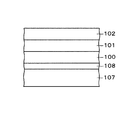
ところで、特許文献1には、液晶表示装置の薄膜トランジスタパネルに適用したものが記載されている(特許文献1の図23〜図27参照)。この薄膜トランジスタパネルの完成した状態における画素電極の部分は、本願の図30に示すような構造となっている。すなわち、酸化シリコンからなる下地絶縁膜100の上面には酸化シリコンからなる層間絶縁膜101が設けられている。層間絶縁膜101の上面には酸化シリコンからなる保護膜102が設けられている。
By the way,
保護膜102、層間絶縁膜101および下地絶縁膜100の所定の箇所には貫通孔103が設けられている。貫通孔103の内壁面、貫通孔103の下部および貫通孔103の周囲における保護膜102の上面には有底筒状の画素電極(薄膜)104が設けられている。画素電極104および保護膜102の上面には、製造工程時の温度に耐えることができない材料からなる基板105が接着層106を介して接着されている。
A through
次に、この薄膜トランジスタパネルの画素電極104の部分の製造方法について説明する。まず、図31に示すように、製造工程時の温度に耐えることができる材料からなる仮基板107の上面にアモルファスシリコンからなる分離層108、酸化シリコンからなる下地絶縁膜100、酸化シリコンからなる層間絶縁膜101および酸化シリコンからなる保護膜102を形成する。
Next, a manufacturing method of the
次に、図32に示すように、保護膜102、層間絶縁膜101および下地絶縁膜100の所定の箇所に、フォトリソグラフィ法により、貫通孔103を形成する。次に、図33に示すように、貫通孔103の内壁面、貫通孔103の下部および貫通孔103の周囲における保護膜102の上面に有底筒状の画素電極104をパターン形成する。
Next, as shown in FIG. 32, through
次に、図34に示すように、画素電極104および保護膜102の上面に基板105を接着層106を介して接着する。次に、図35に示すように、仮基板107の下側からエキシマレーザビームを照射することにより、分離層108から仮基板107を剥離可能な状態とする。次に、分離層108から仮基板107を剥離して除去する。次に、分離層108をエッチングして除去する。かくして、図30に示すものが得られる。
Next, as shown in FIG. 34, a
ところで、図32に示すように、保護膜102、層間絶縁膜101および下地絶縁膜100の所定の箇所に、フォトリソグラフィ法により、貫通孔103を形成するとき、保護膜102等の材料である酸化シリコンと分離層108の材料であるアモルファスシリコンとの間にさほどエッチング選択比がとれないため、実際には、図36(A)に示すように、貫通孔103に対応する部分における分離層108の上面側にある程度の深さの凹部109が形成される。
By the way, as shown in FIG. 32, when the
この結果、図36(B)に示すように、完成した状態では、貫通孔103の下部に形成された画素電極104は下地絶縁膜100の下側にやや突出される。この状態では、貫通孔103内に形成された有底筒状の画素電極104の内部には接着層106が充填されている。しかしながら、有底筒状の画素電極104の内底部周辺部まで接着層106が確実に充填されないおそれがある。このような場合には、画素電極104の厚さが例えば0.05μm程度と極めて薄く、且つ、画素電極104の底部の面積が比較的大きいので、画素電極104の底部周辺部104aが機械的に弱くなり、破損するおそれがあるという問題がある。
As a result, as shown in FIG. 36B, in the completed state, the
そこで、この発明は、画素電極等からなる薄膜が破損しにくいようにすることができる薄膜素子およびその製造方法を提供することを目的とする。 SUMMARY OF THE INVENTION An object of the present invention is to provide a thin film element that can prevent a thin film made of pixel electrodes or the like from being damaged and a method for manufacturing the same.
請求項1に記載の発明に係る薄膜素子は、下面側に凹部を有する絶縁膜と、前記絶縁膜の凹部にべた状に埋め込まれた平板状の薄膜と、前記絶縁膜上に接着層を介して設けられた基板と、を備え、前記絶縁膜は、下地絶縁膜と、該下地絶縁膜上に設けられたゲート絶縁膜と、を有し、前記下地絶縁膜の下面に、前記薄膜としての画素電極が埋め込まれ、前記下地絶縁膜上にゲート電極が設けられ、前記ゲート電極上における前記ゲート絶縁膜上に半導体薄膜が設けられ、前記半導体薄膜上にソース電極およびドレイン電極が設けられ、前記ソース電極、前記ドレイン電極および前記ゲート絶縁膜上に前記基板が前記接着層を介して設けられ、前記ソース電極は前記ゲート絶縁膜および前記下地絶縁膜に設けられた開口部を介して前記画素電極に接続され、前記画素電極の下面は前記下地絶縁膜の下面と面一か上側に位置させられ、前記下地絶縁膜の下面に前記画素電極と同一の材料からなるドレイン配線用外部接続端子が埋め込まれ、前記ゲート絶縁膜上に、前記ドレイン電極に接続されたドレイン配線および該ドレイン配線の一端部に接続されたドレイン配線用接続パッド部が設けられ、前記ドレイン配線用接続パッド部は前記ゲート絶縁膜および前記下地絶縁膜に設けられた別の開口部を介して前記ドレイン配線用外部接続端子に接続され、前記ドレイン配線用外部接続端子の下面は前記下地絶縁膜の下面と面一か上側に位置させられていることを特徴とするものである。
請求項2に記載の発明に係る薄膜素子は、請求項1に記載の発明において、前記基板はフィルム基板であることを特徴とするものである。
請求項3に記載の発明に係る薄膜素子は、下面側に凹部を有する絶縁膜と、前記絶縁膜の凹部にべた状に埋め込まれた平板状の薄膜と、前記絶縁膜上に接着層を介して設けられた基板と、を備え、前記絶縁膜は下地絶縁膜と該下地絶縁膜上に設けられたゲート絶縁膜とを有し、前記下地絶縁膜の下面に、前記薄膜としての画素電極が埋め込まれ、前記下地絶縁膜上にゲート電極が設けられ、前記ゲート電極上における前記ゲート絶縁膜上に半導体薄膜が設けられ、前記半導体薄膜上にソース電極およびドレイン電極が設けられ、前記ソース電極、前記ドレイン電極および前記ゲート絶縁膜上に前記基板が前記接着層を介して設けられ、前記ソース電極は前記ゲート絶縁膜および前記下地絶縁膜に設けられた開口部を介して前記画素電極に接続され、前記画素電極の下面は前記下地絶縁膜の下面と面一か上側に位置させられ、前記下地絶縁膜の下面に前記画素電極と同一の材料からなるゲート配線用外部接続端子が埋め込まれ、前記下地絶縁膜上に前記ゲート電極に接続されたゲート配線および該ゲート配線の一端部に接続されたゲート配線用接続パッド部が設けられ、前記ゲート配線用接続パッド部は前記下地絶縁膜に設けられた別の開口部を介して前記ゲート配線用外部接続端子に接続され、前記ゲート配線用外部接続端子の下面は前記下地絶縁膜の下面と面一か上側に位置させられていることを特徴とするものである。
請求項4に記載の発明に係る薄膜素子は、下面側に凹部を有する絶縁膜と、前記絶縁膜の凹部にべた状に埋め込まれた平板状の薄膜と、前記絶縁膜上に接着層を介して設けられた基板と、を備え、前記絶縁膜は下地絶縁膜と該下地絶縁膜上に設けられたゲート絶縁膜とを有し、前記下地絶縁膜の下面に、前記薄膜としての画素電極が埋め込まれ、前記下地絶縁膜上にゲート電極が設けられ、前記ゲート電極上における前記ゲート絶縁膜上に半導体薄膜が設けられ、前記半導体薄膜上にソース電極およびドレイン電極が設けられ、前記ソース電極、前記ドレイン電極および前記ゲート絶縁膜上に前記基板が前記接着層を介して設けられ、前記ソース電極は前記ゲート絶縁膜および前記下地絶縁膜に設けられた開口部を介して前記画素電極に接続され、前記画素電極の下面は前記下地絶縁膜の下面と面一か上側に位置させられ、前記下地絶縁膜の下面に前記画素電極と同一の材料からなるゲート配線用外部接続端子が埋め込まれ、前記下地絶縁膜上に前記ゲート電極に接続されたゲート配線および該ゲート配線の一端部に接続されたゲート配線用接続パッド部が設けられ、前記ゲート絶縁膜上にゲート配線用中継配線が前記ゲート配線用外部接続端子および前記ゲート配線用接続パッド部に接続されて設けられ、前記ゲート配線用外部接続端子の下面は前記下地絶縁膜の下面と面一か上側に位置させられていることを特徴とするものである。
請求項5に記載の発明に係る薄膜素子は、下面側に凹部を有する絶縁膜と、前記絶縁膜の凹部にべた状に埋め込まれた平板状の薄膜と、前記絶縁膜上に接着層を介して設けられた基板と、を備え、前記絶縁膜は下地絶縁膜と該下地絶縁膜上に設けられたゲート絶縁膜とを有し、前記下地絶縁膜の下面に前記薄膜としての画素電極が埋め込まれ、前記下地絶縁膜上にゲート電極が設けられ、前記ゲート電極上における前記ゲート絶縁膜上に半導体薄膜が設けられ、前記半導体薄膜上にソース電極およびドレイン電極が設けられ、前記ソース電極、前記ドレイン電極および前記ゲート絶縁膜上に前記基板が前記接着層を介して設けられ、前記ソース電極は前記ゲート絶縁膜および前記下地絶縁膜に設けられた開口部を介して前記画素電極に接続され、前記画素電極の下面は前記下地絶縁膜の下面と面一か上側に位置させられ、前記ゲート絶縁膜上に前記ドレイン電極に接続されたドレイン配線および該ドレイン配線の一端部に接続されたドレイン配線用外部接続端子が設けられ、前記ドレイン配線用外部接続端子は前記ゲート絶縁膜および前記下地絶縁膜に設けられた別の開口部の内壁面、前記別の開口部の下部および前記別の開口部の周囲における前記ゲート絶縁膜の上面に設けられ、前記別の開口部の下部に設けられた前記ドレイン配線用外部接続端子の下面は前記下地絶縁膜の下面と面一か下側に突出されていることを特徴とするものである。
請求項6に記載の発明に係る薄膜素子は、下面側に凹部を有する絶縁膜と、前記絶縁膜の凹部にべた状に埋め込まれた平板状の薄膜と、前記絶縁膜上に接着層を介して設けられた基板と、を備え、前記絶縁膜は下地絶縁膜と該下地絶縁膜上に設けられたゲート絶縁膜とを有し、前記下地絶縁膜の下面に、前記薄膜としての画素電極が埋め込まれ、前記下地絶縁膜上にゲート電極が設けられ、前記ゲート電極上における前記ゲート絶縁膜上に半導体薄膜が設けられ、前記半導体薄膜上にソース電極およびドレイン電極が設けられ、前記ソース電極、前記ドレイン電極および前記ゲート絶縁膜上に前記基板が前記接着層を介して設けられ、前記ソース電極は前記ゲート絶縁膜および前記下地絶縁膜に設けられた開口部を介して前記画素電極に接続され、前記画素電極の下面は前記下地絶縁膜の下面と面一か上側に位置させられ、前記下地絶縁膜上に前記ゲート電極に接続されたゲート配線および該ゲート配線の一端部に接続されたゲート配線用接続パッド部が設けられ、前記ゲート絶縁膜上に前記ゲート配線用接続パッド部に接続されたゲート配線用中継配線および該ゲート配線用中継配線に接続されたゲート配線用外部接続端子が設けられ、前記ゲート配線用外部接続端子は前記ゲート絶縁膜および前記下地絶縁膜に設けられた別の開口部の内壁面、前記別の開口部の下部および前記別の開口部の周囲における前記ゲート絶縁膜の上面に設けられ、前記別の開口部の下部に設けられた前記ゲート配線用外部接続端子の下面は前記下地絶縁膜の下面と面一か下側に突出されていることを特徴とするものである。
請求項7に記載の発明に係る薄膜素子の製造方法は、仮基板上に分離層を形成する工程と、前記分離層の上面に薄膜材料を成膜し、エッチングによりパターニングして薄膜を形成する工程と、前記薄膜上および前記分離層上に絶縁膜を形成する工程と、前記絶縁膜上に基板を、接着層を介して接着する工程と、前記仮基板および前記分離層を除去する工程と、を有し、前記薄膜を形成する工程は、前記分離層の上面の一部に前記薄膜としての画素電極を形成する工程を含み、前記絶縁膜を形成する工程は、前記画素電極が形成された部分を含む前記分離層上に下地絶縁膜を形成し、前記下地絶縁膜上にゲート電極を形成し、前記ゲート電極を含む前記下地絶縁膜上にゲート絶縁膜を形成する工程を含み、前記ゲート電極上における前記ゲート絶縁膜上に半導体薄膜を形成する工程を有し、前記半導体薄膜上にソース電極およびドレイン電極を形成し、且つ、前記ソース電極を前記画素電極に接続する工程を有し、前記基板を接着する工程は、前記ソース電極、前記ドレイン電極および前記ゲート絶縁膜上に前記基板を、前記接着層を介して接着する工程を含み、前記画素電極を形成する工程は、前記分離層の上面に前記画素電極と同一の材料からなるドレイン配線用外部接続端子を形成する工程を含み、前記ソース電極および前記ドレイン電極を形成する工程は、前記ゲート絶縁膜上に前記ドレイン電極に接続されたドレイン配線および該ドレイン配線の一端部に接続されたドレイン配線用接続パッド部を形成し、且つ、前記ドレイン配線用接続パッド部を前記ドレイン配線用外部接続端子に接続させる工程を含み、前記下地絶縁膜の下面に平板状の前記ドレイン配線用外部接続端子が埋め込まれ、且つ、前記ドレイン配線用外部接続端子の下面が前記下地絶縁膜の下面と面一か上側に位置させられた薄膜素子を得ることを特徴とするものである。
請求項8に記載の発明に係る薄膜素子の製造方法は、請求項7に記載の発明において、前記分離層はアモルファスシリコンによって形成し、前記仮基板および前記分離層を除去する工程は、前記仮基板の下側からレーザビームを照射して前記分離層から前記仮基板を剥離可能な状態とする工程と、前記分離層から前記仮基板を剥離して除去する工程と、前記分離層をエッチングして除去する工程とを含むことを特徴とするものである。
請求項9に記載の発明に係る薄膜素子の製造方法は、請求項7に記載の発明において、前記分離層は酸化亜鉛によって形成し、前記仮基板および前記分離層を除去する工程は、前記分離層をエッチングして除去することにより、前記仮基板を自然に剥離して除去する工程であることを特徴とするものである。
請求項10に記載の発明に係る薄膜素子の製造方法は、請求項7に記載の発明において、前記仮基板はガラス基板であることを特徴とするものである。
請求項11に記載の発明に係る薄膜素子の製造方法は、請求項7に記載の発明において、前記基板はフィルム基板であることを特徴とするものである。
請求項12に記載の発明に係る薄膜素子の製造方法は、仮基板上に分離層を形成する工程と、前記分離層の上面に薄膜材料を成膜し、エッチングによりパターニングして薄膜を形成する工程と、前記薄膜上および前記分離層上に絶縁膜を形成する工程と、前記絶縁膜上に基板を、接着層を介して接着する工程と、前記仮基板および前記分離層を除去する工程と、を有し、前記薄膜を形成する工程は、前記分離層の上面の一部に前記薄膜としての画素電極を形成する工程を含み、前記絶縁膜を形成する工程は、前記画素電極が形成された部分を含む前記分離層上に下地絶縁膜を形成し、前記下地絶縁膜上にゲート電極を形成し、前記ゲート電極を含む前記下地絶縁膜上にゲート絶縁膜を形成する工程を含み、前記ゲート電極上における前記ゲート絶縁膜上に半導体薄膜を形成する工程を有し、前記半導体薄膜上にソース電極およびドレイン電極を形成し、且つ、前記ソース電極を前記画素電極に接続する工程を有し、前記基板を接着する工程は、前記ソース電極、前記ドレイン電極および前記ゲート絶縁膜上に前記基板を、前記接着層を介して接着する工程を含み、前記画素電極を形成する工程は、前記分離層の上面に前記画素電極と同一の材料からなるゲート配線用外部接続端子を形成する工程を含み、前記ゲート電極を形成する工程は、前記下地絶縁膜上に前記ゲート電極に接続されたゲート配線および該ゲート配線の一端部に接続されたゲート配線用接続パッド部を形成し、且つ、前記ゲート配線用接続パッド部を前記ゲート配線用外部接続端子に接続させる工程を含み、前記下地絶縁膜の下面に平板状の前記ゲート配線用外部接続端子が埋め込まれ、且つ、前記ゲート配線用外部接続端子の下面が前記下地絶縁膜の下面と面一か上側に位置させられた薄膜素子を得ることを特徴とするものである。
請求項13に記載の発明に係る薄膜素子の製造方法は、仮基板上に分離層を形成する工程と、前記分離層の上面に薄膜材料を成膜し、エッチングによりパターニングして薄膜を形成する工程と、前記薄膜上および前記分離層上に絶縁膜を形成する工程と、前記絶縁膜上に基板を、接着層を介して接着する工程と、前記仮基板および前記分離層を除去する工程と、を有し、前記薄膜を形成する工程は、前記分離層の上面の一部に前記薄膜としての画素電極を形成する工程を含み、前記絶縁膜を形成する工程は、前記画素電極が形成された部分を含む前記分離層上に下地絶縁膜を形成し、前記下地絶縁膜上にゲート電極を形成し、前記ゲート電極を含む前記下地絶縁膜上にゲート絶縁膜を形成する工程を含み、前記ゲート電極上における前記ゲート絶縁膜上に半導体薄膜を形成する工程を有し、前記半導体薄膜上にソース電極およびドレイン電極を形成し、且つ、前記ソース電極を前記画素電極に接続する工程を有し、前記基板を接着する工程は、前記ソース電極、前記ドレイン電極および前記ゲート絶縁膜上に前記基板を、前記接着層を介して接着する工程を含み、前記画素電極を形成する工程は、前記分離層の上面に前記画素電極と同一の材料からなるゲート配線用外部接続端子を形成する工程を含み、前記ゲート電極を形成する工程は、前記下地絶縁膜上に前記ゲート電極に接続されたゲート配線および該ゲート配線の一端部に接続されたゲート配線用接続パッド部を形成する工程を含み、前記ソース電極および前記ドレイン電極を形成する工程は、前記ゲート絶縁膜上にゲート配線用中継配線を前記ゲート配線用外部接続端子および前記ゲート配線用接続パッド部に接続させて形成する工程を含み、前記下地絶縁膜の下面に平板状の前記ゲート配線用外部接続端子が埋め込まれ、且つ、前記ゲート配線用外部接続端子の下面が前記下地絶縁膜の下面と面一か上側に位置させられた薄膜素子を得ることを特徴とするものである。
請求項14に記載の発明に係る薄膜素子の製造方法は、仮基板上に分離層を形成する工程と、前記分離層の上面に薄膜材料を成膜し、エッチングによりパターニングして薄膜を形成する工程と、前記薄膜上および前記分離層上に絶縁膜を形成する工程と、前記絶縁膜上に基板を、接着層を介して接着する工程と、前記仮基板および前記分離層を除去する工程と、を有し、前記薄膜を形成する工程は、前記分離層の上面の一部に前記薄膜としての画素電極を形成する工程を含み、前記絶縁膜を形成する工程は、前記画素電極が形成された部分を含む前記分離層上に下地絶縁膜を形成し、前記下地絶縁膜上にゲート電極を形成し、前記ゲート電極を含む前記下地絶縁膜上にゲート絶縁膜を形成する工程を含み、前記ゲート電極上における前記ゲート絶縁膜上に半導体薄膜を形成する工程を有し、前記半導体薄膜上にソース電極およびドレイン電極を形成し、且つ、前記ソース電極を前記画素電極に接続する工程を有し、前記基板を接着する工程は、前記ソース電極、前記ドレイン電極および前記ゲート絶縁膜上に前記基板を、前記接着層を介して接着する工程を含み、前記ソース電極および前記ドレイン電極を形成する工程の前に、前記ゲート絶縁膜および前記下地絶縁膜に貫通孔を形成する工程を有し、前記ソース電極および前記ドレイン電極を形成する工程は、前記ゲート絶縁膜上に前記ドレイン電極に接続されたドレイン配線を形成し、且つ、前記貫通孔の内壁面、前記貫通孔の下部および前記貫通孔の周囲における前記ゲート絶縁膜の上面に前記ドレイン配線に接続されたドレイン配線用外部接続端子を形成する工程を含み、前記貫通孔の下部に形成された前記ドレイン配線用外部接続端子の下面が前記下地絶縁膜の下面と面一か下側に突出された薄膜素子を得ることを特徴とするものである。
請求項15に記載の発明に係る薄膜素子の製造方法は、仮基板上に分離層を形成する工程と、前記分離層の上面に薄膜材料を成膜し、エッチングによりパターニングして薄膜を形成する工程と、前記薄膜上および前記分離層上に絶縁膜を形成する工程と、前記絶縁膜上に基板を、接着層を介して接着する工程と、前記仮基板および前記分離層を除去する工程と、を有し、前記薄膜を形成する工程は、前記分離層の上面の一部に前記薄膜としての画素電極を形成する工程を含み、前記絶縁膜を形成する工程は、前記画素電極が形成された部分を含む前記分離層上に下地絶縁膜を形成し、前記下地絶縁膜上にゲート電極を形成し、前記ゲート電極を含む前記下地絶縁膜上にゲート絶縁膜を形成する工程を含み、前記ゲート電極上における前記ゲート絶縁膜上に半導体薄膜を形成する工程を有し、前記半導体薄膜上にソース電極およびドレイン電極を形成し、且つ、前記ソース電極を前記画素電極に接続する工程を有し、前記基板を接着する工程は、前記ソース電極、前記ドレイン電極および前記ゲート絶縁膜上に前記基板を、前記接着層を介して接着する工程を含み、前記ゲート電極を形成する工程は、前記下地絶縁膜上に前記ゲート電極に接続されたゲート配線および該ゲート配線の一端部に接続されたゲート配線用接続パッド部を形成する工程を含み、前記ソース電極および前記ドレイン電極を形成する工程の前に、前記ゲート配線用接続パッド部に対応する部分における前記ゲート絶縁膜に別の開口部を形成し、且つ、その近傍における前記ゲート絶縁膜および前記下地絶縁膜に貫通孔を形成する工程を有し、前記ソース電極および前記ドレイン電極を形成する工程は、前記ゲート絶縁膜上にゲート配線用中継配線を前記別の開口部を介して前記ゲート配線用接続パッド部に接続させて形成し、且つ、前記貫通孔の内壁面、前記貫通孔の下部および前記貫通孔の周囲における前記ゲート絶縁膜の上面に前記ゲート配線用中継配線に接続されたゲート配線用外部接続端子を形成する工程を含み、前記貫通孔の下部に形成された前記ゲート配線用外部接続端子の下面が前記下地絶縁膜の下面と面一か下側に突出された薄膜素子を得ることを特徴とするものである。
The thin film element according to the first aspect of the invention includes an insulating film having a recess on a lower surface side, a flat thin film embedded in a recess in the insulating film, and an adhesive layer on the insulating film. And the insulating film includes a base insulating film and a gate insulating film provided on the base insulating film, and the lower surface of the base insulating film is formed as the thin film. A pixel electrode is embedded, a gate electrode is provided on the base insulating film, a semiconductor thin film is provided on the gate insulating film on the gate electrode, a source electrode and a drain electrode are provided on the semiconductor thin film, The substrate is provided on the source electrode, the drain electrode, and the gate insulating film through the adhesive layer, and the source electrode is connected to the pixel electrode through an opening provided in the gate insulating film and the base insulating film. The lower surface of the pixel electrode is positioned flush with or above the lower surface of the base insulating film, and an external connection terminal for drain wiring made of the same material as the pixel electrode is embedded in the lower surface of the base insulating film. On the gate insulating film, a drain wiring connected to the drain electrode and a drain wiring connection pad connected to one end of the drain wiring are provided, and the drain wiring connection pad is formed on the gate insulating film. The drain wiring external connection terminal is connected to the drain wiring external connection terminal through another opening provided in the base insulating film, and the lower surface of the drain wiring external connection terminal is positioned flush with or above the lower surface of the base insulating film. It is made to be made to be characterized.
A thin film element according to a second aspect of the present invention is the thin film element according to the first aspect, wherein the substrate is a film substrate.
According to a third aspect of the present invention, there is provided a thin film element including an insulating film having a recess on a lower surface side, a flat thin film embedded in a recess in the insulating film, and an adhesive layer on the insulating film. And the insulating film has a base insulating film and a gate insulating film provided on the base insulating film, and a pixel electrode as the thin film is formed on a lower surface of the base insulating film. Embedded, a gate electrode is provided on the base insulating film, a semiconductor thin film is provided on the gate insulating film on the gate electrode, a source electrode and a drain electrode are provided on the semiconductor thin film, the source electrode, The substrate is provided on the drain electrode and the gate insulating film through the adhesive layer, and the source electrode is connected to the pixel electrode through an opening provided in the gate insulating film and the base insulating film. The lower surface of the pixel electrode is positioned flush with or above the lower surface of the base insulating film, and a gate wiring external connection terminal made of the same material as the pixel electrode is embedded in the lower surface of the base insulating film, A gate wiring connected to the gate electrode and a gate wiring connection pad connected to one end of the gate wiring are provided on the base insulating film, and the gate wiring connection pad is provided on the base insulating film. The gate wiring external connection terminal is connected to the gate wiring external connection terminal through another opened portion, and the lower surface of the gate wiring external connection terminal is positioned flush with or above the lower surface of the base insulating film. It is what.
According to a fourth aspect of the present invention, there is provided a thin film element including an insulating film having a recess on a lower surface side, a flat thin film embedded in a recess in the insulating film, and an adhesive layer on the insulating film. And the insulating film has a base insulating film and a gate insulating film provided on the base insulating film, and a pixel electrode as the thin film is formed on a lower surface of the base insulating film. Embedded, a gate electrode is provided on the base insulating film, a semiconductor thin film is provided on the gate insulating film on the gate electrode, a source electrode and a drain electrode are provided on the semiconductor thin film, the source electrode, The substrate is provided on the drain electrode and the gate insulating film through the adhesive layer, and the source electrode is connected to the pixel electrode through an opening provided in the gate insulating film and the base insulating film. The lower surface of the pixel electrode is positioned flush with or above the lower surface of the base insulating film, and a gate wiring external connection terminal made of the same material as the pixel electrode is embedded in the lower surface of the base insulating film, A gate wiring connected to the gate electrode and a gate wiring connection pad connected to one end of the gate wiring are provided on the base insulating film, and a gate wiring relay wiring is provided on the gate insulating film. It is provided connected to the wiring external connection terminal and the gate wiring connection pad, and the lower surface of the gate wiring external connection terminal is positioned flush with or above the lower surface of the base insulating film. It is what.
According to a fifth aspect of the present invention, there is provided a thin film element including an insulating film having a recess on a lower surface side, a flat thin film embedded in the recess of the insulating film, and an adhesive layer on the insulating film. And the insulating film has a base insulating film and a gate insulating film provided on the base insulating film, and the pixel electrode as the thin film is embedded in the lower surface of the base insulating film A gate electrode is provided on the base insulating film, a semiconductor thin film is provided on the gate insulating film on the gate electrode, a source electrode and a drain electrode are provided on the semiconductor thin film, the source electrode, The substrate is provided on the drain electrode and the gate insulating film through the adhesive layer, and the source electrode is connected to the pixel electrode through an opening provided in the gate insulating film and the base insulating film. The lower surface of the pixel electrode is positioned flush with or above the lower surface of the base insulating film, the drain wiring connected to the drain electrode on the gate insulating film, and the drain connected to one end of the drain wiring Wiring external connection terminals are provided, and the drain wiring external connection terminals are the inner wall surfaces of other openings provided in the gate insulating film and the base insulating film, the lower portions of the other openings, and the other openings. The lower surface of the drain wiring external connection terminal provided on the upper surface of the gate insulating film in the periphery of the portion and protruding below the lower surface of the base insulating film is provided below the other opening. It is characterized by that.
According to a sixth aspect of the present invention, there is provided a thin film element including an insulating film having a recess on a lower surface side, a flat thin film embedded in a recess in the insulating film, and an adhesive layer on the insulating film. And the insulating film has a base insulating film and a gate insulating film provided on the base insulating film, and a pixel electrode as the thin film is formed on a lower surface of the base insulating film. Embedded, a gate electrode is provided on the base insulating film, a semiconductor thin film is provided on the gate insulating film on the gate electrode, a source electrode and a drain electrode are provided on the semiconductor thin film, the source electrode, The substrate is provided on the drain electrode and the gate insulating film through the adhesive layer, and the source electrode is connected to the pixel electrode through an opening provided in the gate insulating film and the base insulating film. The lower surface of the pixel electrode is positioned flush with or above the lower surface of the base insulating film, and is connected to the gate wiring connected to the gate electrode and one end of the gate wiring on the base insulating film. A gate wiring connection pad portion is provided, and a gate wiring relay wiring connected to the gate wiring connection pad portion on the gate insulating film and a gate wiring external connection terminal connected to the gate wiring relay wiring. The external connection terminal for gate wiring is provided on the inner wall surface of another opening provided in the gate insulating film and the base insulating film, the lower part of the other opening, and the periphery of the other opening. The lower surface of the external connection terminal for gate wiring, which is provided on the upper surface of the insulating film and is provided below the other opening, protrudes from the lower surface of the base insulating film. It is an butterfly.
According to a seventh aspect of the present invention, there is provided a method of manufacturing a thin film element, comprising: forming a separation layer on a temporary substrate; forming a thin film material on an upper surface of the separation layer; A step, a step of forming an insulating film on the thin film and the separation layer, a step of bonding a substrate on the insulating film via an adhesive layer, a step of removing the temporary substrate and the separation layer, And forming the thin film includes forming a pixel electrode as the thin film on a part of the upper surface of the separation layer, and forming the insulating film includes forming the pixel electrode. Forming a base insulating film on the isolation layer including a portion, forming a gate electrode on the base insulating film, and forming a gate insulating film on the base insulating film including the gate electrode, The gate on the gate electrode Forming a semiconductor thin film on an edge film, forming a source electrode and a drain electrode on the semiconductor thin film, and connecting the source electrode to the pixel electrode, and bonding the substrate The step includes a step of bonding the substrate on the source electrode, the drain electrode, and the gate insulating film through the adhesive layer, and the step of forming the pixel electrode includes forming the pixel electrode on an upper surface of the isolation layer. Forming a drain wiring external connection terminal made of the same material as the electrode, and the step of forming the source electrode and the drain electrode includes a drain wiring connected to the drain electrode on the gate insulating film and the drain wiring A drain wiring connection pad portion connected to one end of the drain wiring is formed, and the drain wiring connection pad portion is connected to the drain wiring external portion. Including a step of connecting to the connection terminal, the flat external connection terminal for the drain wiring is embedded in the lower surface of the base insulating film, and the lower surface of the external connection terminal for the drain wiring faces the lower surface of the base insulating film A thin film element positioned at one or the upper side is obtained.
According to an eighth aspect of the present invention, there is provided a method for manufacturing a thin film element according to the seventh aspect of the invention, wherein the separation layer is formed of amorphous silicon and the temporary substrate and the separation layer are removed. Irradiating a laser beam from below the substrate to make the temporary substrate peelable from the separation layer; peeling the temporary substrate from the separation layer; removing the temporary substrate; and etching the separation layer And removing it.
According to a ninth aspect of the present invention, there is provided the thin film element manufacturing method according to the seventh aspect of the present invention, wherein the separation layer is formed of zinc oxide, and the step of removing the temporary substrate and the separation layer is performed by the separation. It is a step of removing the temporary substrate naturally by removing the layer by etching.
According to a tenth aspect of the present invention, there is provided a method of manufacturing a thin film element according to the seventh aspect, wherein the temporary substrate is a glass substrate.
According to an eleventh aspect of the present invention, in the thin film element manufacturing method according to the seventh aspect of the present invention, the substrate is a film substrate.
Method of manufacturing a thin film device according to the invention of
According to a thirteenth aspect of the present invention, there is provided a method of manufacturing a thin film element, comprising: forming a separation layer on a temporary substrate; forming a thin film material on an upper surface of the separation layer; A step, a step of forming an insulating film on the thin film and the separation layer, a step of bonding a substrate on the insulating film via an adhesive layer, a step of removing the temporary substrate and the separation layer, And forming the thin film includes forming a pixel electrode as the thin film on a part of the upper surface of the separation layer, and forming the insulating film includes forming the pixel electrode. Forming a base insulating film on the isolation layer including a portion, forming a gate electrode on the base insulating film, and forming a gate insulating film on the base insulating film including the gate electrode, The gate on the gate electrode Forming a semiconductor thin film on the insulating film, forming a source electrode and a drain electrode on the semiconductor thin film, and connecting the source electrode to the pixel electrode, and bonding the substrate The step includes a step of bonding the substrate on the source electrode, the drain electrode, and the gate insulating film through the adhesive layer, and the step of forming the pixel electrode includes forming the pixel electrode on an upper surface of the isolation layer. Forming a gate wiring external connection terminal made of the same material as the electrode, wherein the step of forming the gate electrode includes a gate wiring connected to the gate electrode on the base insulating film and one end of the gate wiring Forming a connection pad portion for a gate wiring connected to the portion, and the step of forming the source electrode and the drain electrode includes forming a gate on the gate insulating film Including a step of connecting a line relay wiring to the gate wiring external connection terminal and the gate wiring connection pad portion, and the planar gate wiring external connection terminal is embedded in the lower surface of the base insulating film. In addition, a thin film element is obtained in which the lower surface of the external connection terminal for gate wiring is positioned flush with or above the lower surface of the base insulating film.
The method for manufacturing a thin film element according to
According to a fifteenth aspect of the present invention, there is provided a method of manufacturing a thin film element, comprising: forming a separation layer on a temporary substrate; forming a thin film material on an upper surface of the separation layer; A step, a step of forming an insulating film on the thin film and the separation layer, a step of bonding a substrate on the insulating film via an adhesive layer, a step of removing the temporary substrate and the separation layer, And forming the thin film includes forming a pixel electrode as the thin film on a part of the upper surface of the separation layer, and forming the insulating film includes forming the pixel electrode. Forming a base insulating film on the isolation layer including a portion, forming a gate electrode on the base insulating film, and forming a gate insulating film on the base insulating film including the gate electrode, The gate on the gate electrode Forming a semiconductor thin film on the insulating film, forming a source electrode and a drain electrode on the semiconductor thin film, and connecting the source electrode to the pixel electrode, and bonding the substrate The step includes a step of bonding the substrate on the source electrode, the drain electrode, and the gate insulating film via the adhesive layer, and the step of forming the gate electrode includes forming the gate on the base insulating film. Forming a gate wiring connected to the electrode and a gate wiring connection pad connected to one end of the gate wiring, and before the step of forming the source electrode and the drain electrode, Another opening is formed in the gate insulating film in the portion corresponding to the connection pad portion, and the gate insulating film and the base insulating film in the vicinity thereof are formed. A step of forming a through-hole, and the step of forming the source electrode and the drain electrode includes the step of forming a gate wiring relay wiring on the gate insulating film through the another opening. And an external connection for gate wiring connected to the relay wiring for gate wiring on the inner wall surface of the through hole, the lower portion of the through hole, and the upper surface of the gate insulating film around the through hole Including a step of forming a terminal, wherein a thin film element is obtained in which a lower surface of the external connection terminal for gate wiring formed in a lower portion of the through-hole is protruded from the lower surface of the base insulating film. It is what.
この発明によれば、絶縁膜の下面に平板状の薄膜を埋め込んでいるので、絶縁膜の下面に埋め込まれた平板状の薄膜に局所的に機械的に弱くなる部分が生じることがなく、ひいては薄膜が破損しにくいようにすることができる。 According to the present invention, since the flat thin film is embedded in the lower surface of the insulating film, there is no local mechanically weakened portion in the flat thin film embedded in the lower surface of the insulating film. The thin film can be made difficult to break.
(第1実施形態)
図1はこの発明の第1実施形態としての薄膜トランジスタパネル(薄膜素子)の要部の断面図を示す。この場合、図1の左側から右側に向かって、ドレイン配線用外部接続端子21の部分の断面図、画素電極(薄膜)2を含む薄膜トランジスタ12の部分の断面図、ゲート配線用外部接続端子31の部分の断面図を示す。
(First embodiment)
FIG. 1 shows a cross-sectional view of a main part of a thin film transistor panel (thin film element) as a first embodiment of the present invention. In this case, from the left side to the right side of FIG. 1, the cross-sectional view of the drain wiring
まず、画素電極2を含む薄膜トランジスタ12の部分について説明する。窒化シリコン等の無機材料からなる下地絶縁膜1には下面より凹んだ凹部が形成されおり、該凹部内にはITOからなる平板状の画素電極2が埋め込まれている。この場合、凹部の底面は平坦であり、画素電極2の上面は平坦であることにより、両者はべた状に接触している。画素電極2の厚さは凹部の深さより小さく、画素電極2の下面は下地絶縁膜1の下面よりもやや上側に位置させられている。すなわち、平板状の画素電極2は下地絶縁膜1の下面から凹んだ状態で埋め込まれている。
First, a portion of the
下地絶縁膜1の上面の所定の箇所にはクロム等からなるゲート電極3および該ゲート電極3に接続されたゲート配線4が設けられている。ゲート電極3およびゲート配線4を含む下地絶縁膜1の上面には窒化シリコン等の無機材料からなるゲート絶縁膜5が設けられている。
A
ゲート電極3上におけるゲート絶縁膜5の上面の所定の箇所には真性アモルファスシリコンからなる半導体薄膜6が設けられている。半導体薄膜6の上面ほぼ中央部には窒化シリコン等の無機材料からなるチャネル保護膜7が設けられている。チャネル保護膜7の上面両側およびその両側における半導体薄膜6の上面にはn型アモルファスシリコンからなるオーミックコンタクト層8、9が設けられている。
A semiconductor
一方のオーミックコンタクト層8の上面およびその近傍におけるゲート絶縁膜5の上面にはクロム等からなるソース電極10が設けられている。他方のオーミックコンタクト層9の上面にはクロム等からなるドレイン電極11が設けられている。ここで、ゲート電極3、ゲート絶縁膜5、半導体薄膜6、チャネル保護膜7、オーミックコンタクト層8、9、ソース電極10およびドレイン電極11により、薄膜トランジスタ12が構成されている。
A
画素電極2の所定の箇所に対応する部分におけるゲート絶縁膜5および下地絶縁膜1には第1の開口部13が設けられている。ソース電極10の一端部は、第1の開口部13を介して露出された画素電極2の上面、第1の開口部13の内壁面および第1の開口部13の周囲におけるゲート絶縁膜5の上面に設けられている。この状態では、ソース電極10の一端部は画素電極2に接続されている。ゲート絶縁膜5の上面の所定の箇所にはクロム等からなるドレイン配線14がドレイン電極11に接続されて設けられている。
A
次に、ドレイン配線用外部接続端子21の部分について説明する。下地絶縁膜1の下面の所定の箇所には、画素電極2と同一の材料からなる平板状のドレイン配線用外部接続端子21が埋め込まれている。この場合、ドレイン配線用外部接続端子21の下面は下地絶縁膜1の下面よりもやや上側に位置させられている。すなわち、平板状のドレイン配線用外部接続端子21は下地絶縁膜1の下面から凹んだ状態で埋め込まれている。
Next, the drain wiring
ドレイン配線用外部接続端子21の中央部に対応する部分におけるゲート絶縁膜5および下地絶縁膜1には第2の開口部22が設けられている。第2の開口部22を介して露出されたドレイン配線用外部接続端子21の上面、第2の開口部22の内壁面および第2の開口部22の周囲におけるゲート絶縁膜5の上面には、ドレイン配線14の一端部に接続されたドレイン配線用接続パッド部23が設けられている。この状態では、ドレイン配線用接続パッド部23はドレイン配線用外部接続端子21に接続されている。
A
次に、ゲート配線用外部接続端子31の部分について説明する。下地絶縁膜1の下面の所定の箇所には、画素電極2と同一の材料からなる平板状のゲート配線用外部接続端子31が埋め込まれている。この場合、ゲート配線用外部接続端子31の下面は下地絶縁膜1の下面よりもやや上側に位置させられている。すなわち、平板状のゲート配線用外部接続端子31は下地絶縁膜1の下面から凹んだ状態で埋め込まれている。
Next, the part of the
ゲート配線用外部接続端子31の中央部に対応する部分における下地絶縁膜1には第3の開口部32が設けられている。第3の開口部32を介して露出されたゲート配線用外部接続端子31の上面、第3の開口部32の内壁面および第3の開口部32の周囲における下地絶縁膜1の上面には、ゲート配線4の一端部に接続されたゲート配線用接続パッド部33が設けられている。この状態では、ゲート配線用接続パッド部33はゲート配線用外部接続端子31に接続されている。
A
次に、図1に示す全体について説明する。薄膜トランジスタ12、ドレイン配線14、ドレイン配線用接続パッド部23およびゲート絶縁膜5の上面には、製造工程時の温度に耐えることができない材料であるポリイミド系樹脂等の有機樹脂からなるフィルム基板41の下面がエポキシ系樹脂等からなる接着層42を介して接着されている。
Next, the whole shown in FIG. 1 will be described. On the upper surfaces of the
次に、この薄膜トランジスタバネルの製造方法の一例について説明する。まず、図2に示すように、製造工程時の温度に耐えることができる材料、換言すれば、フィルム基板41を除いて、図1に示す薄膜トランジスタパネルを製造する工程における最高温度よりもガラス転移点が高い材料であるガラス基板等からなる仮基板51の上面に、プラズマCVD法により、アモルファスシリコンからなる分離層52を成膜する。
Next, an example of a method for manufacturing this thin film transistor panel will be described. First, as shown in FIG. 2, a material capable of withstanding the temperature during the manufacturing process, in other words, the glass transition point is higher than the maximum temperature in the process of manufacturing the thin film transistor panel shown in FIG. A
次に、図3に示すように、分離層52の上面の所定の箇所に、スパッタ法により成膜されたITO膜をフォトリソグラフィ法によりパターニングすることにより、画素電極2、
ドレイン配線用外部接続端子21およびゲート配線用外部接続端子31を形成する。この場合、画素電極2、ドレイン配線用外部接続端子21およびゲート配線用外部接続端子31は平板状に形成され、その各上面は同一の平面上に配置されている。
Next, as shown in FIG. 3, the ITO film formed by the sputtering method is patterned at a predetermined position on the upper surface of the
A drain wiring
また、ITO膜を強酸等のエッチング液を用いてウェットエッチングするとき、アモルファスシリコンからなる分離層52はほとんど膜減りしないが、ここでは、本発明では、膜減りの影響が無いことを明確に示すために、画素電極2、ドレイン配線用外部接続端子21およびゲート配線用外部接続端子31下以外の領域における分離層52の膜減り量を大きく図示している。
In addition, when the ITO film is wet-etched using an etching solution such as strong acid, the
次に、図4に示すように、画素電極2、ドレイン配線用外部接続端子21、ゲート配線用外部接続端子31および分離層52の上面に、プラズマCVD法により、窒化シリコン等の無機材料からなる下地絶縁膜1を成膜する。この状態では、平板状の画素電極2、ドレイン配線用外部接続端子21およびゲート配線用外部接続端子31は下地絶縁膜1の下面から少し突き出した位置に埋め込まれている。
Next, as shown in FIG. 4, the upper surfaces of the
次に、図5に示すように、ゲート配線用外部接続端子31の中央部に対応する部分における下地絶縁膜1に、フォトリソグラフィ法により、第3の開口部32を形成する。次に、図6に示すように、第3の開口部32を介して露出されたゲート配線用外部接続端子31の上面を含む下地絶縁膜1の上面の所定の箇所に、スパッタ法により成膜されたクロム等からなる金属膜をフォトリソグラフィ法によりパターニングすることにより、ゲート電極3、該ゲート電極3に接続されたゲート配線4および該ゲート配線4の一端部に接続されたゲート配線用接続パッド部33を形成する。
Next, as shown in FIG. 5, a
次に、図7に示すように、ゲート電極3、ゲート配線4およびゲート配線用接続パッド部33を含む下地絶縁膜1の上面に、プラズマCVD法により、窒化シリコン等の無機材料からなるゲート絶縁膜5、真性アモルファスシリコン膜53および窒化シリコン等の無機材料からなるチャネル保護膜形成用膜54を連続して成膜する。次に、チャネル保護膜形成用膜54をフォトリソグラフィ法によりパターニングすることにより、チャネル保護膜7を形成する。
Next, as shown in FIG. 7, gate insulation made of an inorganic material such as silicon nitride is formed on the upper surface of the
次に、図8に示すように、チャネル保護膜7を含む真性アモルファスシリコン膜53の上面に、プラズマCVD法により、n型アモルファスシリコン膜55を成膜する。次に、n型アモルファスシリコン膜55および真性アモルファスシリコン膜53をフォトリソグラフィ法により連続してパターニングすると、図9に示すように、オーミックコンタクト層8、9および半導体薄膜6が形成される。
Next, as shown in FIG. 8, an n-type
次に、図10に示すように、画素電極2の所定の箇所およびドレイン配線用外部接続端子21の中央部に対応する部分におけるゲート絶縁膜5および下地絶縁膜1に、フォトリソグラフィ法により、第1、第2の開口部13、22を形成する。
Next, as shown in FIG. 10, the
次に、図11に示すように、第1の開口部13を介して露出された画素電極2の上面、第2の開口部22を介して露出されたドレイン配線用外部接続端子21の上面、オーミックコンタクト層8、9の上面およびゲート絶縁膜5の上面の所定の箇所に、スパッタ法により成膜されたクロム等からなる金属膜をフォトリソグラフィ法によりパターニングすることにより、ソース電極10、ドレイン電極11、該ドレイン電極11に接続されたドレイン配線14および該ドレイン配線14の一端部に接続されたドレイン配線用接続パッド部23を形成する。
Next, as shown in FIG. 11, the upper surface of the
次に、図12に示すように、薄膜トランジスタ12、ドレイン配線14、ドレイン配線用接続パッド部23およびゲート絶縁膜5の上面に、透明なエポキシ樹脂をスピンコート法あるいはスクリーン印刷法等を用いて、上面が平坦な接着層42を形成し、該接着層42上に、製造工程時の温度に耐えることができない材料、換言すれば、フィルム基板41を除いて、図1に示す薄膜トランジスタパネルを製造する工程における最高温度よりもガラス転移点が低い材料であるポリイミド系樹脂等の有機樹脂からなるフィルム基板41を接着する。
Next, as shown in FIG. 12, a transparent epoxy resin is applied to the upper surfaces of the
次に、図13に示すように、仮基板51の下側からエキシマレーザビームを照射することにより、分離層52から仮基板51を剥離可能な状態とする。分離層52を水素を含有するアモルファスシリコンによって形成した場合には、エキシマレーザビームの照射により、水素が気体となって放出され、剥離が促進される。次に、分離層52から仮基板51を剥離して除去する。次に、分離層52をエッチングして除去する。かくして、図1に示す薄膜トランジスタパネルが得られる。
Next, as shown in FIG. 13, the
このようにして得られた薄膜トランジスタパネルでは、下地絶縁膜1の下面に平板状の画素電極2を埋め込んでいるので、下地絶縁膜1の下面に埋め込まれた平板状の画素電極2に局所的に機械的に弱くなる部分が生じることがなく、ひいては画素電極2の厚さが例えば0.05μm程度と極めて薄く、且つ、画素電極2の全体の面積が比較的大きくても、画素電極2が破損しにくいようにすることができる。
In the thin film transistor panel thus obtained, since the
なお、図14を参照して明らかな如く、第1実施形態によれば、下地絶縁膜1の下面は画素電極2の下面より下方に突き出している。この突出し量は、図3において、ITO膜をフォトリソグラフィ法によりパターニングして画素電極2を形成する際の分離層52の膜減り量に対応するものである。図3および図14から明らかな如く、分離層52の膜減り量が大きいほど下地絶縁膜1の下面は画素電極2の下面からの突出し量が増大するだけであり、画素電極2が下地絶縁膜1の下面から下方に突き出すことはなく、下地絶縁膜1の下面から凹んだ状態で埋め込まれる状態が変化することがないから、本発明によれば分離層52のエッチング選択性に拘らず同様な効果が得られるものである。
As is apparent with reference to FIG. 14, according to the first embodiment, the lower surface of the
また、ドレイン配線用外部接続端子21およびゲート配線用外部接続端子31を画素電極2と同一の材料によって形成し、且つ、その各下面の高さを同じとすることができるので、これらの外部接続端子21、31に接合されるドライバLSI等との接合の信頼性を高めることができる。また、ゲート配線4とドレイン配線14との材料が異なっても、ドレイン配線用外部接続端子21およびゲート配線用外部接続端子31の材料が同じであるので、これらの外部接続端子21、31に接合されるドライバLSI等との接合の信頼性をより一層高めることができる。
In addition, since the drain wiring
ところで、上記薄膜トランジスタパネルの製造方法では、図5に示すように、第3の開口部32を形成する工程と、図10に示すように、第1、第2の開口部13、22を形成する工程とが別々であるので、フォトリソグラフィ法による工程数が多くなってしまう。そこで、次に、フォトリソグラフィ法による工程数を少なくすることができる実施形態について説明する。
In the thin film transistor panel manufacturing method, as shown in FIG. 5, the step of forming the
(第2実施形態)
図14はこの発明の第2実施形態としての薄膜トランジスタパネルの要部の断面図を示す。この薄膜トランジスタパネルにおいて、図1に示す薄膜トランジスタパネルと異なる点は、ゲート配線用外部接続端子31の部分を異なる構造とした点である。すなわち、下地絶縁膜1の下面の所定の箇所には、画素電極2と同一の材料からなる平板状のゲート配線用外部接続端子31が埋め込まれている。この場合も、ゲート配線用外部接続端子31の下面は下地絶縁膜1の下面よりもやや上側に位置させられている。
(Second Embodiment)
FIG. 14 shows a cross-sectional view of a main part of a thin film transistor panel as a second embodiment of the present invention. The thin film transistor panel is different from the thin film transistor panel shown in FIG. 1 in that the gate wiring
ゲート配線用外部接続端子31の近傍における下地絶縁膜1の上面の所定の箇所には、ゲート配線4の一端部に接続されたゲート配線用接続パッド部33が設けられている。ゲート絶縁膜5の上面の所定の箇所にはゲート配線用中継配線34が設けられている。ゲート配線用中継配線34の一端部は、ゲート絶縁膜5および下地絶縁膜1に設けられた第3の開口部33を介してゲート配線用外部接続端子31に接続されている。ゲート配線用中継配線34の他端部は、ゲート絶縁膜5に設けられた第4の開口部35を介してゲート配線用接続パッド部33に接続されている。
A gate
次に、この薄膜トランジスタバネルの製造方法の一例について説明する。この場合、図4に示す工程後に、図15に示すように、下地絶縁膜1の上面の所定の箇所に、スパッタ法により成膜されたクロム等からなる金属膜をフォトリソグラフィ法によりパターニングすることにより、ゲート電極3、該ゲート電極3に接続されたゲート配線4および該ゲート配線4の一端部に接続されたゲート配線用接続パッド部33を形成する。
Next, an example of a method for manufacturing this thin film transistor panel will be described. In this case, after the step shown in FIG. 4, as shown in FIG. 15, a metal film made of chromium or the like formed by sputtering at a predetermined position on the upper surface of the
次に、図16に示すように、ゲート電極3、ゲート配線4およびゲート配線用接続パッド部33を含む下地絶縁膜1の上面に、プラズマCVD法により、窒化シリコン等の無機材料からなるゲート絶縁膜5、真性アモルファスシリコン膜53および窒化シリコン等の無機材料からなるチャネル保護膜形成用膜54を連続して成膜する。次に、チャネル保護膜形成用膜54をフォトリソグラフィ法によりパターニングすることにより、チャネル保護膜7を形成する。
Next, as shown in FIG. 16, gate insulation made of an inorganic material such as silicon nitride is formed on the upper surface of the
次に、図17に示すように、チャネル保護膜7を含む真性アモルファスシリコン膜53の上面に、プラズマCVD法により、n型アモルファスシリコン膜55を成膜する。次に、n型アモルファスシリコン膜55および真性アモルファスシリコン膜53をフォトリソグラフィ法により連続してパターニングすると、図18に示すように、オーミックコンタクト層8、9および半導体薄膜6が形成される。
Next, as shown in FIG. 17, an n-type
次に、図19に示すように、フォトリソグラフィ法により、画素電極2の所定の箇所、ドレイン配線用外部接続端子21の中央部およびゲート配線用外部接続端子31の中央部に対応する部分におけるゲート絶縁膜5および下地絶縁膜1に第1〜第3の開口部13、22、32を形成し、且つ、ゲート配線用接続パッド部33の中央部に対応する部分におけるゲート絶縁膜5に第4の開口部35を形成する。
Next, as shown in FIG. 19, by photolithography, gates at predetermined portions of the
次に、図20に示すように、第1の開口部13を介して露出された画素電極2の上面、第2の開口部22を介して露出されたドレイン配線用外部接続端子21の上面、第3の開口部32を介して露出されたゲート配線用外部接続端子31の上面、第4の開口部35を介して露出されたゲート配線用接続パッド部33の上面、オーミックコンタクト層8、9の上面およびゲート絶縁膜5の上面の所定の箇所に、スパッタ法により成膜されたクロム等からなる金属膜をフォトリソグラフィ法によりパターニングすることにより、ソース電極10、ドレイン電極11、該ドレイン電極11に接続されたドレイン配線14、該ドレイン配線14の一端部に接続されたドレイン配線用接続パッド部23およびゲート配線用中継配線34を形成する。
Next, as shown in FIG. 20, the upper surface of the
以下、上記第1実施形態の場合と同様の工程を経ると、図14に示す薄膜トランジスタパネルが得られる。以上のように、この薄膜トランジスタパネルの製造方法では、図19に示すように、第1〜第4の開口部13、22、32、35を同一の工程で形成しているので、上記第1実施形態の場合と比較して、フォトリソグラフィ法による工程を1回だけ少なくすることができる。
Thereafter, through the same steps as in the first embodiment, the thin film transistor panel shown in FIG. 14 is obtained. As described above, in this thin film transistor panel manufacturing method, as shown in FIG. 19, the first to
(第3実施形態)
図21はこの発明の第3実施形態としての薄膜トランジスタパネルの要部の断面図を示す。この薄膜トランジスタパネルにおいて、図1に示す薄膜トランジスタパネルと異なる点は、ドレイン配線用外部接続端子21の部分およびゲート配線用外部接続端子31の部分を異なる構造とした点である。
(Third embodiment)
FIG. 21 is a sectional view showing the main part of a thin film transistor panel according to a third embodiment of the present invention. This thin film transistor panel is different from the thin film transistor panel shown in FIG. 1 in that the drain wiring
まず、ドレイン配線用外部接続端子21の部分について説明する。ドレイン配線用外部接続端子21は、ゲート絶縁膜5および下地絶縁膜1の所定の箇所に設けられた第1の貫通孔61の内壁面、第1の貫通孔61の下部および第1の貫通孔61の周囲におけるゲート絶縁膜5の上面に設けられている。
First, the drain wiring
この場合、ドレイン配線用外部接続端子21は、ドレイン配線14と同一の材料によって形成され、ドレイン配線14の一端部に接続されている。また、第1の貫通孔61の下部に設けられたドレイン配線用外部接続端子21は下地絶縁膜1の下側にやや突出され、この突出部分の下面は平坦となっている。
In this case, the drain wiring
次に、ゲート配線用外部接続端子31の部分について説明する。ゲート配線用外部接続端子31は、ゲート絶縁膜5および下地絶縁膜1の所定の箇所に設けられた第2の貫通孔62の内壁面、第2の貫通孔62の下部および第2の貫通孔62の周囲におけるゲート絶縁膜5の上面に設けられている。この場合、ゲート配線用外部接続端子31はドレイン配線14と同一の材料によって形成されている。
Next, the part of the
下地絶縁膜1の上面の所定の箇所には、ゲート配線4の一端部に接続されたゲート配線用接続パッド部33が設けられている。ゲート絶縁膜5の上面の所定の箇所にはゲート配線用中継配線34が設けられている。ゲート配線用中継配線34の一端部はゲート配線用外部接続端子31に接続されている。ゲート配線用中継配線34の他端部は、ゲート絶縁膜5に設けられた第4の開口部35を介してゲート配線用接続パッド部33に接続されている。
A gate
次に、この薄膜トランジスタバネルの製造方法の一例について説明する。この場合、図2に示す工程後に、図22に示すように、分離層52の上面の所定の箇所に、スパッタ法により成膜されたITO膜をフォトリソグラフィ法によりパターニングすることにより、平板状の画素電極2を形成する。この場合も、画素電極2下以外の領域における分離層52が僅かに膜減りしたとする。
Next, an example of a method for manufacturing this thin film transistor panel will be described. In this case, after the step shown in FIG. 2, as shown in FIG. 22, an ITO film formed by sputtering at a predetermined position on the upper surface of the
次に、図23に示すように、画素電極2および分離層52の上面に、プラズマCVD法により、窒化シリコン等の無機材料からなる下地絶縁膜1を成膜する。この状態では、平板状の画素電極2は下地絶縁膜1の下面に凹んだ状態で埋め込まれている。
Next, as shown in FIG. 23, a
次に、図24に示すように、下地絶縁膜1の上面の所定の箇所に、スパッタ法により成膜されたクロム等からなる金属膜をフォトリソグラフィ法によりパターニングすることにより、ゲート電極3、該ゲート電極3に接続されたゲート配線4および該ゲート配線4の一端部に接続されたゲート配線用接続パッド部33を形成する。
Next, as shown in FIG. 24, by patterning a metal film made of chromium or the like formed by sputtering at a predetermined position on the upper surface of the
次に、図25に示すように、ゲート電極3、ゲート配線4およびゲート配線用接続パッド部33を含む下地絶縁膜1の上面に、プラズマCVD法により、窒化シリコン等の無機材料からなるゲート絶縁膜5、真性アモルファスシリコン膜53および窒化シリコン等の無機材料からなるチャネル保護膜形成用膜54を連続して成膜する。次に、チャネル保護膜形成用膜54をフォトリソグラフィ法によりパターニングすることにより、チャネル保護膜7を形成する。
Next, as shown in FIG. 25, gate insulation made of an inorganic material such as silicon nitride is formed on the upper surface of the
次に、図26に示すように、チャネル保護膜7を含む真性アモルファスシリコン膜53の上面に、プラズマCVD法により、n型アモルファスシリコン膜55を成膜する。次に、n型アモルファスシリコン膜55および真性アモルファスシリコン膜53をフォトリソグラフィ法により連続してパターニングすると、図27に示すように、オーミックコンタクト層8、9および半導体薄膜6が形成される。
Next, as shown in FIG. 26, an n-type
次に、図28に示すように、フォトリソグラフィ法により、画素電極2の所定の箇所、ドレイン配線用外部接続端子形成領域の所定の箇所およびゲート配線用外部接続端子形成領域の所定の箇所におけるゲート絶縁膜5および下地絶縁膜1に第1の開口部13および第1、第2の貫通孔61、62を形成し、且つ、ゲート配線用接続パッド部33の中央部に対応する部分におけるゲート絶縁膜5に第4の開口部35を形成する。この場合、第1、第2の貫通孔61、62を介して分離層52の上面が露出されるため、この露出された部分における分離層52が僅かに膜減りする。
Next, as shown in FIG. 28, gates at predetermined locations of the
次に、図29に示すように、第1の開口部13を介して露出された画素電極2の上面、第1、第2の貫通孔61、62を介して露出された分離層52の上面、第4の開口部35を介して露出されたゲート配線用接続パッド部33の上面、オーミックコンタクト層8、9の上面およびゲート絶縁膜5の上面の所定の箇所に、スパッタ法により成膜されたクロム等からなる金属膜をフォトリソグラフィ法によりパターニングすることにより、ソース電極10、ドレイン電極11、該ドレイン電極11に接続されたドレイン配線14、該ドレイン配線14の一端部に接続されたドレイン配線用外部接続端子21、ゲート配線用外部接続端子31およびゲート配線用中継配線34を形成する。
Next, as shown in FIG. 29, the upper surface of the
以下、上記第1実施形態の場合と同様の工程を経ると、図21に示す薄膜トランジスタパネルが得られる。このようにして得られた薄膜トランジスタパネルでは、ドレイン配線用外部接続端子21およびゲート配線用外部接続端子31をドレイン配線14と同一の材料によって形成し、且つ、その各下面の高さを同じとすることができるので、これらの外部接続端子21、31に接合されるドライバLSI等との接合の信頼性を高めることができる。また、ドレイン配線用外部接続端子21およびゲート配線用外部接続端子3をクロム等によって形成すると、上記第1、第2実施形態のように、ITOによって形成する場合と比較して、ITO膜との接触抵抗がなくなるので、これらの外部接続端子21、31の抵抗を低く抑えることができる。
Thereafter, through the same steps as in the first embodiment, the thin film transistor panel shown in FIG. 21 is obtained. In the thin film transistor panel thus obtained, the drain wiring
(その他の実施形態)
上記各実施形態では、分離膜52が僅かに膜減りする場合について説明したが、分離膜52がほとんど膜減りしない場合には、図1、図14および図21において、画素電極2、ドレイン配線用外部接続端子21およびゲート配線用外部接続端子3の下面は下地絶縁膜1の下面と面一となるようにしてもよい。
(Other embodiments)
In each of the above embodiments, the case where the
また、上記各実施形態では、分離層52をアモルファスシリコンによって形成した場合について説明したが、これに限定されるものではない。例えば、分離層52を酸化亜鉛によって形成するようにしてもよい。この場合、例えば、図12に示す工程後に、エッチング液(例えば、0.5w%酢酸水溶液)に浸すと、酸化亜鉛からなる分離層52が溶解して除去され、仮基板51が自然に剥離して除去される。
In each of the above embodiments, the case where the
1 下地絶縁膜
2 画素電極
3 ゲート電極
4 ゲート配線
5 ゲート絶縁膜
6 半導体薄膜
7 チャネル保護膜
8、9 オーミックコンタクト層
10 ソース電極
11 ドレイン電極
12 薄膜トランジスタ
13 第1の開口部
14 ドレイン配線
21 ドレイン配線用外部接続端子
22 第2の開口部
23 ドレイン配線用接続パッド部
31 ゲート配線用外部接続端子
32 第3の開口部
33 ゲート配線用接続パッド部
34 ゲート配線用中継配線
35 第5の開口部
41 フィルム基板
42 接着層
51 仮基板
52 分離層
53 真性アモルファスシリコン膜
54 チャネル保護膜形成用膜
55 n型アモルファスシリコン膜
61 第1の貫通孔
62 第2の貫通孔
DESCRIPTION OF
Claims (15)
膜と、前記絶縁膜上に接着層を介して設けられた基板と、を備え、
前記絶縁膜は、下地絶縁膜と、該下地絶縁膜上に設けられたゲート絶縁膜と、を有し、
前記下地絶縁膜の下面に、前記薄膜としての画素電極が埋め込まれ、
前記下地絶縁膜上にゲート電極が設けられ、
前記ゲート電極上における前記ゲート絶縁膜上に半導体薄膜が設けられ、
前記半導体薄膜上にソース電極およびドレイン電極が設けられ、
前記ソース電極、前記ドレイン電極および前記ゲート絶縁膜上に前記基板が前記接着層を介して設けられ、
前記ソース電極は前記ゲート絶縁膜および前記下地絶縁膜に設けられた開口部を介して前記画素電極に接続され、
前記画素電極の下面は前記下地絶縁膜の下面と面一か上側に位置させられ、
前記下地絶縁膜の下面に前記画素電極と同一の材料からなるドレイン配線用外部接続端子が埋め込まれ、
前記ゲート絶縁膜上に、前記ドレイン電極に接続されたドレイン配線および該ドレイン配線の一端部に接続されたドレイン配線用接続パッド部が設けられ、
前記ドレイン配線用接続パッド部は前記ゲート絶縁膜および前記下地絶縁膜に設けられた別の開口部を介して前記ドレイン配線用外部接続端子に接続され、
前記ドレイン配線用外部接続端子の下面は前記下地絶縁膜の下面と面一か上側に位置させられていることを特徴とする薄膜素子。 An insulating film having a recess on the lower surface side, a flat thin film embedded in a recess in the insulating film, and a substrate provided on the insulating film via an adhesive layer,
The insulating film has a base insulating film and a gate insulating film provided on the base insulating film,
A pixel electrode as the thin film is embedded in the lower surface of the base insulating film,
A gate electrode is provided on the base insulating film;
A semiconductor thin film is provided on the gate insulating film on the gate electrode;
A source electrode and a drain electrode are provided on the semiconductor thin film,
The substrate is provided on the source electrode, the drain electrode, and the gate insulating film via the adhesive layer,
The source electrode is connected to the pixel electrode through an opening provided in the gate insulating film and the base insulating film,
The lower surface of the pixel electrode is positioned flush with or above the lower surface of the base insulating film,
An external connection terminal for drain wiring made of the same material as the pixel electrode is embedded in the lower surface of the base insulating film,
A drain wiring connected to the drain electrode and a drain wiring connection pad connected to one end of the drain wiring are provided on the gate insulating film,
The drain wiring connection pad is connected to the drain wiring external connection terminal through another opening provided in the gate insulating film and the base insulating film,
The thin film element, wherein the lower surface of the drain wiring external connection terminal is positioned flush with or above the lower surface of the base insulating film.
前記絶縁膜は下地絶縁膜と該下地絶縁膜上に設けられたゲート絶縁膜とを有し、
前記下地絶縁膜の下面に、前記薄膜としての画素電極が埋め込まれ、
前記下地絶縁膜上にゲート電極が設けられ、
前記ゲート電極上における前記ゲート絶縁膜上に半導体薄膜が設けられ、
前記半導体薄膜上にソース電極およびドレイン電極が設けられ、
前記ソース電極、前記ドレイン電極および前記ゲート絶縁膜上に前記基板が前記接着層を介して設けられ、
前記ソース電極は前記ゲート絶縁膜および前記下地絶縁膜に設けられた開口部を介して前記画素電極に接続され、
前記画素電極の下面は前記下地絶縁膜の下面と面一か上側に位置させられ、
前記下地絶縁膜の下面に前記画素電極と同一の材料からなるゲート配線用外部接続端子が埋め込まれ、
前記下地絶縁膜上に前記ゲート電極に接続されたゲート配線および該ゲート配線の一端部に接続されたゲート配線用接続パッド部が設けられ、
前記ゲート配線用接続パッド部は前記下地絶縁膜に設けられた別の開口部を介して前記ゲート配線用外部接続端子に接続され、
前記ゲート配線用外部接続端子の下面は前記下地絶縁膜の下面と面一か上側に位置させられていることを特徴とする薄膜素子。 An insulating film having a recess on the lower surface side, a flat thin film embedded in a recess in the insulating film, and a substrate provided on the insulating film via an adhesive layer,
The insulating film has a base insulating film and a gate insulating film provided on the base insulating film,
A pixel electrode as the thin film is embedded in the lower surface of the base insulating film,
A gate electrode is provided on the base insulating film;
A semiconductor thin film is provided on the gate insulating film on the gate electrode;
A source electrode and a drain electrode are provided on the semiconductor thin film,
The substrate is provided on the source electrode, the drain electrode, and the gate insulating film via the adhesive layer,
The source electrode is connected to the pixel electrode through an opening provided in the gate insulating film and the base insulating film,
The lower surface of the pixel electrode is positioned flush with or above the lower surface of the base insulating film,
An external connection terminal for gate wiring made of the same material as the pixel electrode is embedded in the lower surface of the base insulating film,
A gate wiring connected to the gate electrode and a gate wiring connection pad connected to one end of the gate wiring are provided on the base insulating film,
The gate wiring connection pad is connected to the gate wiring external connection terminal through another opening provided in the base insulating film,
The thin film element according to claim 1, wherein the lower surface of the external connection terminal for gate wiring is positioned flush with or above the lower surface of the base insulating film.
前記絶縁膜は下地絶縁膜と該下地絶縁膜上に設けられたゲート絶縁膜とを有し、
前記下地絶縁膜の下面に、前記薄膜としての画素電極が埋め込まれ、
前記下地絶縁膜上にゲート電極が設けられ、
前記ゲート電極上における前記ゲート絶縁膜上に半導体薄膜が設けられ、
前記半導体薄膜上にソース電極およびドレイン電極が設けられ、
前記ソース電極、前記ドレイン電極および前記ゲート絶縁膜上に前記基板が前記接着層を介して設けられ、
前記ソース電極は前記ゲート絶縁膜および前記下地絶縁膜に設けられた開口部を介して前記画素電極に接続され、
前記画素電極の下面は前記下地絶縁膜の下面と面一か上側に位置させられ、
前記下地絶縁膜の下面に前記画素電極と同一の材料からなるゲート配線用外部接続端子が埋め込まれ、
前記下地絶縁膜上に前記ゲート電極に接続されたゲート配線および該ゲート配線の一端部に接続されたゲート配線用接続パッド部が設けられ、
前記ゲート絶縁膜上にゲート配線用中継配線が前記ゲート配線用外部接続端子および前記ゲート配線用接続パッド部に接続されて設けられ、
前記ゲート配線用外部接続端子の下面は前記下地絶縁膜の下面と面一か上側に位置させられていることを特徴とする薄膜素子。 An insulating film having a recess on the lower surface side, a flat thin film embedded in a recess in the insulating film, and a substrate provided on the insulating film via an adhesive layer,
The insulating film has a base insulating film and a gate insulating film provided on the base insulating film,
A pixel electrode as the thin film is embedded in the lower surface of the base insulating film,
A gate electrode is provided on the base insulating film;
A semiconductor thin film is provided on the gate insulating film on the gate electrode;
A source electrode and a drain electrode are provided on the semiconductor thin film,
The substrate is provided on the source electrode, the drain electrode, and the gate insulating film via the adhesive layer,
The source electrode is connected to the pixel electrode through an opening provided in the gate insulating film and the base insulating film,
The lower surface of the pixel electrode is positioned flush with or above the lower surface of the base insulating film,
An external connection terminal for gate wiring made of the same material as the pixel electrode is embedded in the lower surface of the base insulating film,
A gate wiring connected to the gate electrode and a gate wiring connection pad connected to one end of the gate wiring are provided on the base insulating film,
On the gate insulating film, a relay wiring for gate wiring is provided connected to the external connection terminal for gate wiring and the connection pad portion for gate wiring,
The thin film element according to claim 1, wherein the lower surface of the external connection terminal for gate wiring is positioned flush with or above the lower surface of the base insulating film.
前記絶縁膜は下地絶縁膜と該下地絶縁膜上に設けられたゲート絶縁膜とを有し、
前記下地絶縁膜の下面に前記薄膜としての画素電極が埋め込まれ、
前記下地絶縁膜上にゲート電極が設けられ、
前記ゲート電極上における前記ゲート絶縁膜上に半導体薄膜が設けられ、
前記半導体薄膜上にソース電極およびドレイン電極が設けられ、
前記ソース電極、前記ドレイン電極および前記ゲート絶縁膜上に前記基板が前記接着層を介して設けられ、
前記ソース電極は前記ゲート絶縁膜および前記下地絶縁膜に設けられた開口部を介して前記画素電極に接続され、
前記画素電極の下面は前記下地絶縁膜の下面と面一か上側に位置させられ、
前記ゲート絶縁膜上に前記ドレイン電極に接続されたドレイン配線および該ドレイン配線の一端部に接続されたドレイン配線用外部接続端子が設けられ、
前記ドレイン配線用外部接続端子は前記ゲート絶縁膜および前記下地絶縁膜に設けられた別の開口部の内壁面、前記別の開口部の下部および前記別の開口部の周囲における前記ゲート絶縁膜の上面に設けられ、
前記別の開口部の下部に設けられた前記ドレイン配線用外部接続端子の下面は前記下地絶縁膜の下面と面一か下側に突出されていることを特徴とする薄膜素子。 An insulating film having a recess on the lower surface side, a flat thin film embedded in a recess in the insulating film, and a substrate provided on the insulating film via an adhesive layer,
The insulating film has a base insulating film and a gate insulating film provided on the base insulating film,
A pixel electrode as the thin film is embedded on the lower surface of the base insulating film,
A gate electrode is provided on the base insulating film;
A semiconductor thin film is provided on the gate insulating film on the gate electrode;
A source electrode and a drain electrode are provided on the semiconductor thin film,
The substrate is provided on the source electrode, the drain electrode, and the gate insulating film via the adhesive layer,
The source electrode is connected to the pixel electrode through an opening provided in the gate insulating film and the base insulating film,
The lower surface of the pixel electrode is positioned flush with or above the lower surface of the base insulating film,
A drain wiring connected to the drain electrode and a drain wiring external connection terminal connected to one end of the drain wiring are provided on the gate insulating film,
The drain wiring external connection terminal includes an inner wall surface of another opening provided in the gate insulating film and the base insulating film, a lower portion of the other opening, and a periphery of the other opening. Provided on the top surface,
The thin film element according to claim 1, wherein a lower surface of the drain wiring external connection terminal provided at a lower portion of the other opening protrudes flush with or below the lower surface of the base insulating film.
前記絶縁膜は下地絶縁膜と該下地絶縁膜上に設けられたゲート絶縁膜とを有し、
前記下地絶縁膜の下面に、前記薄膜としての画素電極が埋め込まれ、
前記下地絶縁膜上にゲート電極が設けられ、
前記ゲート電極上における前記ゲート絶縁膜上に半導体薄膜が設けられ、
前記半導体薄膜上にソース電極およびドレイン電極が設けられ、
前記ソース電極、前記ドレイン電極および前記ゲート絶縁膜上に前記基板が前記接着層を介して設けられ、
前記ソース電極は前記ゲート絶縁膜および前記下地絶縁膜に設けられた開口部を介して前記画素電極に接続され、
前記画素電極の下面は前記下地絶縁膜の下面と面一か上側に位置させられ、
前記下地絶縁膜上に前記ゲート電極に接続されたゲート配線および該ゲート配線の一端部に接続されたゲート配線用接続パッド部が設けられ、
前記ゲート絶縁膜上に前記ゲート配線用接続パッド部に接続されたゲート配線用中継配線および該ゲート配線用中継配線に接続されたゲート配線用外部接続端子が設けられ、
前記ゲート配線用外部接続端子は前記ゲート絶縁膜および前記下地絶縁膜に設けられた別の開口部の内壁面、前記別の開口部の下部および前記別の開口部の周囲における前記ゲート絶縁膜の上面に設けられ、
前記別の開口部の下部に設けられた前記ゲート配線用外部接続端子の下面は前記下地絶縁膜の下面と面一か下側に突出されていることを特徴とする薄膜素子。 An insulating film having a recess on the lower surface side, a flat thin film embedded in a recess in the insulating film, and a substrate provided on the insulating film via an adhesive layer,
The insulating film has a base insulating film and a gate insulating film provided on the base insulating film,
A pixel electrode as the thin film is embedded in the lower surface of the base insulating film,
A gate electrode is provided on the base insulating film;
A semiconductor thin film is provided on the gate insulating film on the gate electrode;
A source electrode and a drain electrode are provided on the semiconductor thin film,
The substrate is provided on the source electrode, the drain electrode, and the gate insulating film via the adhesive layer,
The source electrode is connected to the pixel electrode through an opening provided in the gate insulating film and the base insulating film,
The lower surface of the pixel electrode is the base insulating film was found is located on the lower surface flush with or above the,
A gate wiring connected to the gate electrode and a gate wiring connection pad connected to one end of the gate wiring are provided on the base insulating film,
A gate wiring relay wiring connected to the gate wiring connection pad portion and a gate wiring external connection terminal connected to the gate wiring relay wiring are provided on the gate insulating film,
The external connection terminal for gate wiring includes an inner wall surface of another opening provided in the gate insulating film and the base insulating film, a lower portion of the other opening, and a periphery of the other opening. Provided on the top surface,
A thin film element, wherein a lower surface of the external connection terminal for gate wiring provided at a lower portion of the other opening protrudes to be flush with or below the lower surface of the base insulating film.
前記分離層の上面に薄膜材料を成膜し、エッチングによりパターニングして薄膜を形成する工程と、
前記薄膜上および前記分離層上に絶縁膜を形成する工程と、
前記絶縁膜上に基板を、接着層を介して接着する工程と、
前記仮基板および前記分離層を除去する工程と、
を有し、
前記薄膜を形成する工程は、前記分離層の上面の一部に前記薄膜としての画素電極を形成する工程を含み、
前記絶縁膜を形成する工程は、前記画素電極が形成された部分を含む前記分離層上に下地絶縁膜を形成し、前記下地絶縁膜上にゲート電極を形成し、前記ゲート電極を含む前記下地絶縁膜上にゲート絶縁膜を形成する工程を含み、
前記ゲート電極上における前記ゲート絶縁膜上に半導体薄膜を形成する工程を有し、
前記半導体薄膜上にソース電極およびドレイン電極を形成し、且つ、前記ソース電極を前記画素電極に接続する工程を有し、
前記基板を接着する工程は、前記ソース電極、前記ドレイン電極および前記ゲート絶縁膜上に前記基板を、前記接着層を介して接着する工程を含み、
前記画素電極を形成する工程は、前記分離層の上面に前記画素電極と同一の材料からなるドレイン配線用外部接続端子を形成する工程を含み、
前記ソース電極および前記ドレイン電極を形成する工程は、前記ゲート絶縁膜上に前記ドレイン電極に接続されたドレイン配線および該ドレイン配線の一端部に接続されたドレイン配線用接続パッド部を形成し、且つ、前記ドレイン配線用接続パッド部を前記ドレイン配線用外部接続端子に接続させる工程を含み、
前記下地絶縁膜の下面に平板状の前記ドレイン配線用外部接続端子が埋め込まれ、且つ、前記ドレイン配線用外部接続端子の下面が前記下地絶縁膜の下面と面一か上側に位置させられた薄膜素子を得ることを特徴とする薄膜素子の製造方法。 Forming a separation layer on the temporary substrate;
Forming a thin film material on the upper surface of the separation layer and patterning by etching to form a thin film;
Forming an insulating film on the thin film and on the separation layer;
Bonding the substrate on the insulating film via an adhesive layer;
Removing the temporary substrate and the separation layer;
Have
The step of forming the thin film includes a step of forming a pixel electrode as the thin film on a part of the upper surface of the separation layer,
The step of forming the insulating film includes forming a base insulating film on the isolation layer including a portion where the pixel electrode is formed, forming a gate electrode on the base insulating film, and forming the base including the gate electrode. Including a step of forming a gate insulating film on the insulating film,
Forming a semiconductor thin film on the gate insulating film on the gate electrode;
Forming a source electrode and a drain electrode on the semiconductor thin film, and connecting the source electrode to the pixel electrode;
The step of bonding the substrate includes the step of bonding the substrate on the source electrode, the drain electrode, and the gate insulating film through the bonding layer,
The step of forming the pixel electrode includes a step of forming a drain wiring external connection terminal made of the same material as the pixel electrode on the upper surface of the isolation layer,
The step of forming the source electrode and the drain electrode includes forming a drain wiring connected to the drain electrode on the gate insulating film and a connection pad portion for drain wiring connected to one end of the drain wiring, and And connecting the drain wiring connection pad portion to the drain wiring external connection terminal,
A thin film in which a flat plate-like external connection terminal for drain wiring is embedded in the lower surface of the base insulating film, and the lower surface of the external connection terminal for drain wiring is positioned flush with or above the lower surface of the base insulating film A method for producing a thin film element, comprising obtaining an element.
前記分離層の上面に薄膜材料を成膜し、エッチングによりパターニングして薄膜を形成する工程と、
前記薄膜上および前記分離層上に絶縁膜を形成する工程と、
前記絶縁膜上に基板を、接着層を介して接着する工程と、
前記仮基板および前記分離層を除去する工程と、
を有し、
前記薄膜を形成する工程は、前記分離層の上面の一部に前記薄膜としての画素電極を形成する工程を含み、
前記絶縁膜を形成する工程は、前記画素電極が形成された部分を含む前記分離層上に下地絶縁膜を形成し、前記下地絶縁膜上にゲート電極を形成し、前記ゲート電極を含む前記下地絶縁膜上にゲート絶縁膜を形成する工程を含み、
前記ゲート電極上における前記ゲート絶縁膜上に半導体薄膜を形成する工程を有し、
前記半導体薄膜上にソース電極およびドレイン電極を形成し、且つ、前記ソース電極を前記画素電極に接続する工程を有し、
前記基板を接着する工程は、前記ソース電極、前記ドレイン電極および前記ゲート絶縁膜上に前記基板を、前記接着層を介して接着する工程を含み、
前記画素電極を形成する工程は、前記分離層の上面に前記画素電極と同一の材料からなるゲート配線用外部接続端子を形成する工程を含み、
前記ゲート電極を形成する工程は、前記下地絶縁膜上に前記ゲート電極に接続されたゲート配線および該ゲート配線の一端部に接続されたゲート配線用接続パッド部を形成し、且つ、前記ゲート配線用接続パッド部を前記ゲート配線用外部接続端子に接続させる工程を含み、
前記下地絶縁膜の下面に平板状の前記ゲート配線用外部接続端子が埋め込まれ、且つ、前記ゲート配線用外部接続端子の下面が前記下地絶縁膜の下面と面一か上側に位置させられた薄膜素子を得ることを特徴とする薄膜素子の製造方法。 Forming a separation layer on the temporary substrate;
Forming a thin film material on the upper surface of the separation layer and patterning by etching to form a thin film;
Forming an insulating film on the thin film and on the separation layer;
Bonding the substrate on the insulating film via an adhesive layer;
Removing the temporary substrate and the separation layer;
Have
The step of forming the thin film includes a step of forming a pixel electrode as the thin film on a part of the upper surface of the separation layer,
The step of forming the insulating film includes forming a base insulating film on the isolation layer including a portion where the pixel electrode is formed, forming a gate electrode on the base insulating film, and forming the base including the gate electrode. Including a step of forming a gate insulating film on the insulating film,
Forming a semiconductor thin film on the gate insulating film on the gate electrode;
Forming a source electrode and a drain electrode on the semiconductor thin film, and connecting the source electrode to the pixel electrode;
The step of bonding the substrate includes the step of bonding the substrate on the source electrode, the drain electrode, and the gate insulating film through the bonding layer,
The step of forming the pixel electrode includes a step of forming an external connection terminal for gate wiring made of the same material as the pixel electrode on the upper surface of the separation layer,
The step of forming the gate electrode includes forming a gate wiring connected to the gate electrode and a connection pad portion for gate wiring connected to one end of the gate wiring on the base insulating film, and the gate wiring Including a step of connecting a connection pad portion for use to the external connection terminal for gate wiring,
A thin film in which the planar external connection terminal for gate wiring is embedded in the lower surface of the base insulating film, and the lower surface of the external connection terminal for gate wiring is positioned flush with or above the lower surface of the base insulating film A method for producing a thin film element, comprising obtaining an element.
前記分離層の上面に薄膜材料を成膜し、エッチングによりパターニングして薄膜を形成する工程と、
前記薄膜上および前記分離層上に絶縁膜を形成する工程と、
前記絶縁膜上に基板を、接着層を介して接着する工程と、
前記仮基板および前記分離層を除去する工程と、
を有し、
前記薄膜を形成する工程は、前記分離層の上面の一部に前記薄膜としての画素電極を形成する工程を含み、
前記絶縁膜を形成する工程は、前記画素電極が形成された部分を含む前記分離層上に下地絶縁膜を形成し、前記下地絶縁膜上にゲート電極を形成し、前記ゲート電極を含む前記下地絶縁膜上にゲート絶縁膜を形成する工程を含み、
前記ゲート電極上における前記ゲート絶縁膜上に半導体薄膜を形成する工程を有し、
前記半導体薄膜上にソース電極およびドレイン電極を形成し、且つ、前記ソース電極を前記画素電極に接続する工程を有し、
前記基板を接着する工程は、前記ソース電極、前記ドレイン電極および前記ゲート絶縁膜上に前記基板を、前記接着層を介して接着する工程を含み、
前記画素電極を形成する工程は、前記分離層の上面に前記画素電極と同一の材料からなるゲート配線用外部接続端子を形成する工程を含み、
前記ゲート電極を形成する工程は、前記下地絶縁膜上に前記ゲート電極に接続されたゲート配線および該ゲート配線の一端部に接続されたゲート配線用接続パッド部を形成する工程を含み、
前記ソース電極および前記ドレイン電極を形成する工程は、前記ゲート絶縁膜上にゲート配線用中継配線を前記ゲート配線用外部接続端子および前記ゲート配線用接続パッド部に接続させて形成する工程を含み、
前記下地絶縁膜の下面に平板状の前記ゲート配線用外部接続端子が埋め込まれ、且つ、前記ゲート配線用外部接続端子の下面が前記下地絶縁膜の下面と面一か上側に位置させられた薄膜素子を得ることを特徴とする薄膜素子の製造方法。 Forming a separation layer on the temporary substrate;
Forming a thin film material on the upper surface of the separation layer and patterning by etching to form a thin film;
Forming an insulating film on the thin film and on the separation layer;
Bonding the substrate on the insulating film via an adhesive layer;
Removing the temporary substrate and the separation layer;
Have
The step of forming the thin film includes a step of forming a pixel electrode as the thin film on a part of the upper surface of the separation layer,
The step of forming the insulating film includes forming a base insulating film on the isolation layer including a portion where the pixel electrode is formed, forming a gate electrode on the base insulating film, and forming the base including the gate electrode. Including a step of forming a gate insulating film on the insulating film,
Forming a semiconductor thin film on the gate insulating film on the gate electrode;
Forming a source electrode and a drain electrode on the semiconductor thin film, and connecting the source electrode to the pixel electrode;
The step of bonding the substrate includes the step of bonding the substrate on the source electrode, the drain electrode, and the gate insulating film through the bonding layer,
The step of forming the pixel electrode includes a step of forming an external connection terminal for gate wiring made of the same material as the pixel electrode on the upper surface of the separation layer,
The step of forming the gate electrode includes a step of forming a gate wiring connected to the gate electrode and a connection pad portion for gate wiring connected to one end of the gate wiring on the base insulating film,
The step of forming the source electrode and the drain electrode includes a step of connecting a gate wiring relay wiring to the gate wiring external connection terminal and the gate wiring connection pad on the gate insulating film,
A thin film in which the planar external connection terminal for gate wiring is embedded in the lower surface of the base insulating film, and the lower surface of the external connection terminal for gate wiring is positioned flush with or above the lower surface of the base insulating film A method for producing a thin film element, comprising obtaining an element.
前記分離層の上面に薄膜材料を成膜し、エッチングによりパターニングして薄膜を形成する工程と、
前記薄膜上および前記分離層上に絶縁膜を形成する工程と、
前記絶縁膜上に基板を、接着層を介して接着する工程と、
前記仮基板および前記分離層を除去する工程と、
を有し、
前記薄膜を形成する工程は、前記分離層の上面の一部に前記薄膜としての画素電極を形成する工程を含み、
前記絶縁膜を形成する工程は、前記画素電極が形成された部分を含む前記分離層上に下地絶縁膜を形成し、前記下地絶縁膜上にゲート電極を形成し、前記ゲート電極を含む前記下地絶縁膜上にゲート絶縁膜を形成する工程を含み、
前記ゲート電極上における前記ゲート絶縁膜上に半導体薄膜を形成する工程を有し、
前記半導体薄膜上にソース電極およびドレイン電極を形成し、且つ、前記ソース電極を前記画素電極に接続する工程を有し、
前記基板を接着する工程は、前記ソース電極、前記ドレイン電極および前記ゲート絶縁膜上に前記基板を、前記接着層を介して接着する工程を含み、
前記ソース電極および前記ドレイン電極を形成する工程の前に、前記ゲート絶縁膜および前記下地絶縁膜に貫通孔を形成する工程を有し、
前記ソース電極および前記ドレイン電極を形成する工程は、前記ゲート絶縁膜上に前記ドレイン電極に接続されたドレイン配線を形成し、且つ、前記貫通孔の内壁面、前記貫通孔の下部および前記貫通孔の周囲における前記ゲート絶縁膜の上面に前記ドレイン配線に接続されたドレイン配線用外部接続端子を形成する工程を含み、
前記貫通孔の下部に形成された前記ドレイン配線用外部接続端子の下面が前記下地絶縁膜の下面と面一か下側に突出された薄膜素子を得ることを特徴とする薄膜素子の製造方法。 Forming a separation layer on the temporary substrate;
Forming a thin film material on the upper surface of the separation layer and patterning by etching to form a thin film;
Forming an insulating film on the thin film and on the separation layer;
Bonding the substrate on the insulating film via an adhesive layer;
Removing the temporary substrate and the separation layer;
Have
The step of forming the thin film includes a step of forming a pixel electrode as the thin film on a part of the upper surface of the separation layer,
The step of forming the insulating film includes forming a base insulating film on the isolation layer including a portion where the pixel electrode is formed, forming a gate electrode on the base insulating film, and forming the base including the gate electrode. Including a step of forming a gate insulating film on the insulating film,
Forming a semiconductor thin film on the gate insulating film on the gate electrode;
Forming a source electrode and a drain electrode on the semiconductor thin film, and connecting the source electrode to the pixel electrode;
The step of bonding the substrate includes the step of bonding the substrate on the source electrode, the drain electrode, and the gate insulating film through the bonding layer,
Before the step of forming the source electrode and the drain electrode, the step of forming a through hole in the gate insulating film and the base insulating film,
The step of forming the source electrode and the drain electrode includes forming a drain wiring connected to the drain electrode on the gate insulating film, and forming an inner wall surface of the through hole, a lower portion of the through hole, and the through hole. Forming a drain wiring external connection terminal connected to the drain wiring on the upper surface of the gate insulating film in the periphery of
A method of manufacturing a thin film element, comprising: obtaining a thin film element in which a lower surface of the drain wiring external connection terminal formed in a lower portion of the through hole protrudes flush with or below a lower surface of the base insulating film.
前記分離層の上面に薄膜材料を成膜し、エッチングによりパターニングして薄膜を形成する工程と、
前記薄膜上および前記分離層上に絶縁膜を形成する工程と、
前記絶縁膜上に基板を、接着層を介して接着する工程と、
前記仮基板および前記分離層を除去する工程と、
を有し、
前記薄膜を形成する工程は、前記分離層の上面の一部に前記薄膜としての画素電極を形成する工程を含み、
前記絶縁膜を形成する工程は、前記画素電極が形成された部分を含む前記分離層上に下地絶縁膜を形成し、前記下地絶縁膜上にゲート電極を形成し、前記ゲート電極を含む前記下地絶縁膜上にゲート絶縁膜を形成する工程を含み、
前記ゲート電極上における前記ゲート絶縁膜上に半導体薄膜を形成する工程を有し、
前記半導体薄膜上にソース電極およびドレイン電極を形成し、且つ、前記ソース電極を前記画素電極に接続する工程を有し、
前記基板を接着する工程は、前記ソース電極、前記ドレイン電極および前記ゲート絶縁膜上に前記基板を、前記接着層を介して接着する工程を含み、
前記ゲート電極を形成する工程は、前記下地絶縁膜上に前記ゲート電極に接続されたゲート配線および該ゲート配線の一端部に接続されたゲート配線用接続パッド部を形成する工程を含み、
前記ソース電極および前記ドレイン電極を形成する工程の前に、前記ゲート配線用接続パッド部に対応する部分における前記ゲート絶縁膜に別の開口部を形成し、且つ、その近傍における前記ゲート絶縁膜および前記下地絶縁膜に貫通孔を形成する工程を有し、前記ソース電極および前記ドレイン電極を形成する工程は、前記ゲート絶縁膜上にゲート配線用中継配線を前記別の開口部を介して前記ゲート配線用接続パッド部に接続させて形成し、且つ、前記貫通孔の内壁面、前記貫通孔の下部および前記貫通孔の周囲における前記ゲート絶縁膜の上面に前記ゲート配線用中継配線に接続されたゲート配線用外部接続端子を形成する工程を含み、
前記貫通孔の下部に形成された前記ゲート配線用外部接続端子の下面が前記下地絶縁膜の下面と面一か下側に突出された薄膜素子を得ることを特徴とする薄膜素子の製造方法。 Forming a separation layer on the temporary substrate;
Forming a thin film material on the upper surface of the separation layer and patterning by etching to form a thin film;
Forming an insulating film on the thin film and on the separation layer;
Bonding the substrate on the insulating film via an adhesive layer;
Removing the temporary substrate and the separation layer;
Have
The step of forming the thin film includes a step of forming a pixel electrode as the thin film on a part of the upper surface of the separation layer,
The step of forming the insulating film includes forming a base insulating film on the isolation layer including a portion where the pixel electrode is formed, forming a gate electrode on the base insulating film, and forming the base including the gate electrode. Including a step of forming a gate insulating film on the insulating film,
Forming a semiconductor thin film on the gate insulating film on the gate electrode;
Forming a source electrode and a drain electrode on the semiconductor thin film, and connecting the source electrode to the pixel electrode;
The step of bonding the substrate includes the step of bonding the substrate on the source electrode, the drain electrode, and the gate insulating film through the bonding layer,
The step of forming the gate electrode includes a step of forming a gate wiring connected to the gate electrode and a connection pad portion for gate wiring connected to one end of the gate wiring on the base insulating film,
Before the step of forming the source electrode and the drain electrode, another opening is formed in the gate insulating film in a portion corresponding to the gate wiring connection pad portion, and the gate insulating film in the vicinity thereof and A step of forming a through-hole in the base insulating film, and the step of forming the source electrode and the drain electrode includes the step of forming a gate wiring relay wiring on the gate insulating film through the another opening. Connected to the connection pad portion for wiring, and connected to the relay wiring for gate wiring on the inner wall surface of the through hole, the lower portion of the through hole, and the upper surface of the gate insulating film around the through hole Including a step of forming an external connection terminal for gate wiring,
A method of manufacturing a thin film element, comprising: obtaining a thin film element in which a lower surface of the external connection terminal for gate wiring formed in a lower portion of the through-hole is protruded from the lower surface of the base insulating film.
Priority Applications (1)
| Application Number | Priority Date | Filing Date | Title |
|---|---|---|---|
| JP2009051538A JP5483151B2 (en) | 2009-03-05 | 2009-03-05 | Thin film element and manufacturing method thereof |
Applications Claiming Priority (1)
| Application Number | Priority Date | Filing Date | Title |
|---|---|---|---|
| JP2009051538A JP5483151B2 (en) | 2009-03-05 | 2009-03-05 | Thin film element and manufacturing method thereof |
Publications (2)
| Publication Number | Publication Date |
|---|---|
| JP2010206040A JP2010206040A (en) | 2010-09-16 |
| JP5483151B2 true JP5483151B2 (en) | 2014-05-07 |
Family
ID=42967222
Family Applications (1)
| Application Number | Title | Priority Date | Filing Date |
|---|---|---|---|
| JP2009051538A Expired - Fee Related JP5483151B2 (en) | 2009-03-05 | 2009-03-05 | Thin film element and manufacturing method thereof |
Country Status (1)
| Country | Link |
|---|---|
| JP (1) | JP5483151B2 (en) |
Families Citing this family (8)
| Publication number | Priority date | Publication date | Assignee | Title |
|---|---|---|---|---|
| CN113419386A (en) | 2015-04-13 | 2021-09-21 | 株式会社半导体能源研究所 | Display panel, data processor and manufacturing method of display panel |
| US10978489B2 (en) | 2015-07-24 | 2021-04-13 | Semiconductor Energy Laboratory Co., Ltd. | Semiconductor device, display panel, method for manufacturing semiconductor device, method for manufacturing display panel, and information processing device |
| WO2017103737A1 (en) | 2015-12-18 | 2017-06-22 | Semiconductor Energy Laboratory Co., Ltd. | Display panel, input/output device, data processing device, and method for manufacturing display panel |
| WO2017178919A1 (en) | 2016-04-12 | 2017-10-19 | 株式会社半導体エネルギー研究所 | Peeling method and flexible device manufacturing method |
| US10181424B2 (en) | 2016-04-12 | 2019-01-15 | Semiconductor Energy Laboratory Co., Ltd. | Peeling method and manufacturing method of flexible device |
| CN109075079B (en) * | 2016-04-22 | 2022-04-15 | 株式会社半导体能源研究所 | Peeling method and method for manufacturing flexible device |
| TW201824222A (en) * | 2016-07-22 | 2018-07-01 | 半導體能源研究所股份有限公司 | Manufacturing method of display device, display device, display module and electronic apparatus |
| KR20180083253A (en) * | 2017-01-12 | 2018-07-20 | 가부시키가이샤 한도오따이 에네루기 켄큐쇼 | Method for manufacturing semiconductor device |
Family Cites Families (7)
| Publication number | Priority date | Publication date | Assignee | Title |
|---|---|---|---|---|
| JP3738799B2 (en) * | 1996-11-22 | 2006-01-25 | セイコーエプソン株式会社 | Active matrix substrate manufacturing method, active matrix substrate, and liquid crystal display device |
| JP3482856B2 (en) * | 1998-01-26 | 2004-01-06 | 株式会社日立製作所 | Liquid crystal display device and method of manufacturing the same |
| CN1195243C (en) * | 1999-09-30 | 2005-03-30 | 三星电子株式会社 | Film transistor array panel for liquid crystal display and its producing method |
| JP2002108246A (en) * | 2000-09-29 | 2002-04-10 | Sharp Corp | Method for manufacturing electronic equipment having resinous substrate and method for manufacturing liquid crystal display device having resinous substrate |
| US20040140469A1 (en) * | 2003-01-17 | 2004-07-22 | Tsung-Neng Liao | Panel of a flat display and method of fabricating the panel |
| JP5138927B2 (en) * | 2006-12-25 | 2013-02-06 | 共同印刷株式会社 | Flexible TFT substrate, manufacturing method thereof and flexible display |
| JP5309672B2 (en) * | 2008-04-21 | 2013-10-09 | カシオ計算機株式会社 | Thin film element and manufacturing method thereof |
-
2009
- 2009-03-05 JP JP2009051538A patent/JP5483151B2/en not_active Expired - Fee Related
Also Published As
| Publication number | Publication date |
|---|---|
| JP2010206040A (en) | 2010-09-16 |
Similar Documents
| Publication | Publication Date | Title |
|---|---|---|
| JP5483151B2 (en) | Thin film element and manufacturing method thereof | |
| CN109671761B (en) | Display panel and manufacturing method thereof | |
| JP5309672B2 (en) | Thin film element and manufacturing method thereof | |
| JP5399494B2 (en) | WIRING BOARD, MANUFACTURING METHOD THEREOF, DISPLAY PANEL, AND DISPLAY DEVICE | |
| JP5149464B2 (en) | Contact structure, substrate, display device, and contact structure and method of manufacturing substrate | |
| US8493541B2 (en) | Array substrate, manufacturing method thereof and liquid crystal display | |
| KR101434452B1 (en) | Array substrate for display device and method of fabricating the same | |
| CN107146818B (en) | Thin film transistor, manufacturing method thereof, array substrate and display device | |
| JP5505757B2 (en) | Method for manufacturing liquid crystal display device and liquid crystal display device | |
| JP5423572B2 (en) | Wiring board, piezoelectric oscillator, gyro sensor, and manufacturing method of wiring board | |
| JP2006196712A (en) | Manufacturing method of thin-film element | |
| JP2011249649A (en) | Semiconductor device | |
| JP2011049303A (en) | Electric component and method of manufacturing the same | |
| US8471993B2 (en) | Common line structure and display panel and method of making the same | |
| JP2010097077A (en) | Display device and manufacturing method thereof | |
| JP2006245159A (en) | Manufacturing method of semiconductor device | |
| TWI437689B (en) | Semiconductor device | |
| JP2011191425A (en) | Array substrate for display device and method for manufacturing the same | |
| JP5900823B2 (en) | Liquid crystal display | |
| JP2007027482A (en) | Semiconductor device and its manufacturing method | |
| JP5521286B2 (en) | Thin film element manufacturing method | |
| JP6028887B2 (en) | Wiring board, infrared sensor, and through electrode forming method | |
| JP5098204B2 (en) | SEMICONDUCTOR DEVICE, ITS MANUFACTURING METHOD, AND ELECTRONIC DEVICE | |
| JP2008085238A (en) | Substrate having through electrode, and manufacturing method thereof | |
| JP2007116029A (en) | Wiring board, method for manufacturing same, and display device |
Legal Events
| Date | Code | Title | Description |
|---|---|---|---|
| A621 | Written request for application examination |
Free format text: JAPANESE INTERMEDIATE CODE: A621 Effective date: 20110930 |
|
| A977 | Report on retrieval |
Free format text: JAPANESE INTERMEDIATE CODE: A971007 Effective date: 20130711 |
|
| A131 | Notification of reasons for refusal |
Free format text: JAPANESE INTERMEDIATE CODE: A131 Effective date: 20130820 |
|
| A521 | Written amendment |
Free format text: JAPANESE INTERMEDIATE CODE: A523 Effective date: 20131018 |
|
| A131 | Notification of reasons for refusal |
Free format text: JAPANESE INTERMEDIATE CODE: A131 Effective date: 20131111 |
|
| A521 | Written amendment |
Free format text: JAPANESE INTERMEDIATE CODE: A523 Effective date: 20140107 |
|
| TRDD | Decision of grant or rejection written | ||
| A01 | Written decision to grant a patent or to grant a registration (utility model) |
Free format text: JAPANESE INTERMEDIATE CODE: A01 Effective date: 20140124 |
|
| A61 | First payment of annual fees (during grant procedure) |
Free format text: JAPANESE INTERMEDIATE CODE: A61 Effective date: 20140206 |
|
| R150 | Certificate of patent or registration of utility model |
Ref document number: 5483151 Country of ref document: JP Free format text: JAPANESE INTERMEDIATE CODE: R150 |
|
| LAPS | Cancellation because of no payment of annual fees |