JP5481040B2 - Display device and driving method thereof - Google Patents
Display device and driving method thereof Download PDFInfo
- Publication number
- JP5481040B2 JP5481040B2 JP2008104079A JP2008104079A JP5481040B2 JP 5481040 B2 JP5481040 B2 JP 5481040B2 JP 2008104079 A JP2008104079 A JP 2008104079A JP 2008104079 A JP2008104079 A JP 2008104079A JP 5481040 B2 JP5481040 B2 JP 5481040B2
- Authority
- JP
- Japan
- Prior art keywords
- electrodes
- pixel
- electrode
- counter
- counter electrodes
- Prior art date
- Legal status (The legal status is an assumption and is not a legal conclusion. Google has not performed a legal analysis and makes no representation as to the accuracy of the status listed.)
- Active
Links
- 238000000034 method Methods 0.000 title claims description 23
- 238000001514 detection method Methods 0.000 claims description 166
- 230000008859 change Effects 0.000 claims description 16
- 239000011159 matrix material Substances 0.000 claims description 14
- 239000002346 layers by function Substances 0.000 claims description 7
- 239000000758 substrate Substances 0.000 description 65
- 239000004973 liquid crystal related substance Substances 0.000 description 64
- 239000010410 layer Substances 0.000 description 30
- 239000011295 pitch Substances 0.000 description 22
- 239000003990 capacitor Substances 0.000 description 18
- 230000004048 modification Effects 0.000 description 17
- 238000012986 modification Methods 0.000 description 17
- 230000005684 electric field Effects 0.000 description 14
- 230000007423 decrease Effects 0.000 description 12
- 238000010586 diagram Methods 0.000 description 12
- 239000010408 film Substances 0.000 description 12
- 230000005540 biological transmission Effects 0.000 description 6
- 239000011521 glass Substances 0.000 description 6
- 239000011241 protective layer Substances 0.000 description 6
- 238000013459 approach Methods 0.000 description 5
- 230000003247 decreasing effect Effects 0.000 description 5
- 230000008901 benefit Effects 0.000 description 4
- 230000012447 hatching Effects 0.000 description 4
- 230000009467 reduction Effects 0.000 description 4
- 238000000926 separation method Methods 0.000 description 4
- 230000035945 sensitivity Effects 0.000 description 3
- 230000015572 biosynthetic process Effects 0.000 description 2
- 239000003086 colorant Substances 0.000 description 2
- 238000007599 discharging Methods 0.000 description 2
- 238000004519 manufacturing process Methods 0.000 description 2
- 230000004044 response Effects 0.000 description 2
- 230000001360 synchronised effect Effects 0.000 description 2
- 239000010409 thin film Substances 0.000 description 2
- 230000003321 amplification Effects 0.000 description 1
- 230000008094 contradictory effect Effects 0.000 description 1
- 238000013461 design Methods 0.000 description 1
- 230000006866 deterioration Effects 0.000 description 1
- 238000010790 dilution Methods 0.000 description 1
- 239000012895 dilution Substances 0.000 description 1
- 230000008034 disappearance Effects 0.000 description 1
- 230000000694 effects Effects 0.000 description 1
- 239000007772 electrode material Substances 0.000 description 1
- 238000005516 engineering process Methods 0.000 description 1
- 238000009499 grossing Methods 0.000 description 1
- 239000000463 material Substances 0.000 description 1
- 238000005259 measurement Methods 0.000 description 1
- 230000000116 mitigating effect Effects 0.000 description 1
- 238000003199 nucleic acid amplification method Methods 0.000 description 1
- 230000003287 optical effect Effects 0.000 description 1
- 230000003071 parasitic effect Effects 0.000 description 1
- 230000002265 prevention Effects 0.000 description 1
- 230000008569 process Effects 0.000 description 1
- 238000007493 shaping process Methods 0.000 description 1
- 230000001052 transient effect Effects 0.000 description 1
- 230000007704 transition Effects 0.000 description 1
Images


Classifications
-
- G—PHYSICS
- G06—COMPUTING; CALCULATING OR COUNTING
- G06F—ELECTRIC DIGITAL DATA PROCESSING
- G06F3/00—Input arrangements for transferring data to be processed into a form capable of being handled by the computer; Output arrangements for transferring data from processing unit to output unit, e.g. interface arrangements
- G06F3/01—Input arrangements or combined input and output arrangements for interaction between user and computer
- G06F3/03—Arrangements for converting the position or the displacement of a member into a coded form
- G06F3/041—Digitisers, e.g. for touch screens or touch pads, characterised by the transducing means
- G06F3/0412—Digitisers structurally integrated in a display
-
- G—PHYSICS
- G02—OPTICS
- G02F—OPTICAL DEVICES OR ARRANGEMENTS FOR THE CONTROL OF LIGHT BY MODIFICATION OF THE OPTICAL PROPERTIES OF THE MEDIA OF THE ELEMENTS INVOLVED THEREIN; NON-LINEAR OPTICS; FREQUENCY-CHANGING OF LIGHT; OPTICAL LOGIC ELEMENTS; OPTICAL ANALOGUE/DIGITAL CONVERTERS
- G02F1/00—Devices or arrangements for the control of the intensity, colour, phase, polarisation or direction of light arriving from an independent light source, e.g. switching, gating or modulating; Non-linear optics
- G02F1/01—Devices or arrangements for the control of the intensity, colour, phase, polarisation or direction of light arriving from an independent light source, e.g. switching, gating or modulating; Non-linear optics for the control of the intensity, phase, polarisation or colour
- G02F1/13—Devices or arrangements for the control of the intensity, colour, phase, polarisation or direction of light arriving from an independent light source, e.g. switching, gating or modulating; Non-linear optics for the control of the intensity, phase, polarisation or colour based on liquid crystals, e.g. single liquid crystal display cells
- G02F1/133—Constructional arrangements; Operation of liquid crystal cells; Circuit arrangements
- G02F1/1333—Constructional arrangements; Manufacturing methods
- G02F1/13338—Input devices, e.g. touch panels
-
- G—PHYSICS
- G02—OPTICS
- G02F—OPTICAL DEVICES OR ARRANGEMENTS FOR THE CONTROL OF LIGHT BY MODIFICATION OF THE OPTICAL PROPERTIES OF THE MEDIA OF THE ELEMENTS INVOLVED THEREIN; NON-LINEAR OPTICS; FREQUENCY-CHANGING OF LIGHT; OPTICAL LOGIC ELEMENTS; OPTICAL ANALOGUE/DIGITAL CONVERTERS
- G02F1/00—Devices or arrangements for the control of the intensity, colour, phase, polarisation or direction of light arriving from an independent light source, e.g. switching, gating or modulating; Non-linear optics
- G02F1/01—Devices or arrangements for the control of the intensity, colour, phase, polarisation or direction of light arriving from an independent light source, e.g. switching, gating or modulating; Non-linear optics for the control of the intensity, phase, polarisation or colour
- G02F1/13—Devices or arrangements for the control of the intensity, colour, phase, polarisation or direction of light arriving from an independent light source, e.g. switching, gating or modulating; Non-linear optics for the control of the intensity, phase, polarisation or colour based on liquid crystals, e.g. single liquid crystal display cells
- G02F1/133—Constructional arrangements; Operation of liquid crystal cells; Circuit arrangements
- G02F1/1333—Constructional arrangements; Manufacturing methods
- G02F1/1343—Electrodes
- G02F1/134309—Electrodes characterised by their geometrical arrangement
- G02F1/134363—Electrodes characterised by their geometrical arrangement for applying an electric field parallel to the substrate, i.e. in-plane switching [IPS]
-
- G—PHYSICS
- G06—COMPUTING; CALCULATING OR COUNTING
- G06F—ELECTRIC DIGITAL DATA PROCESSING
- G06F3/00—Input arrangements for transferring data to be processed into a form capable of being handled by the computer; Output arrangements for transferring data from processing unit to output unit, e.g. interface arrangements
- G06F3/01—Input arrangements or combined input and output arrangements for interaction between user and computer
- G06F3/03—Arrangements for converting the position or the displacement of a member into a coded form
- G06F3/041—Digitisers, e.g. for touch screens or touch pads, characterised by the transducing means
- G06F3/044—Digitisers, e.g. for touch screens or touch pads, characterised by the transducing means by capacitive means
- G06F3/0445—Digitisers, e.g. for touch screens or touch pads, characterised by the transducing means by capacitive means using two or more layers of sensing electrodes, e.g. using two layers of electrodes separated by a dielectric layer
-
- G—PHYSICS
- G09—EDUCATION; CRYPTOGRAPHY; DISPLAY; ADVERTISING; SEALS
- G09G—ARRANGEMENTS OR CIRCUITS FOR CONTROL OF INDICATING DEVICES USING STATIC MEANS TO PRESENT VARIABLE INFORMATION
- G09G3/00—Control arrangements or circuits, of interest only in connection with visual indicators other than cathode-ray tubes
- G09G3/20—Control arrangements or circuits, of interest only in connection with visual indicators other than cathode-ray tubes for presentation of an assembly of a number of characters, e.g. a page, by composing the assembly by combination of individual elements arranged in a matrix no fixed position being assigned to or needed to be assigned to the individual characters or partial characters
- G09G3/34—Control arrangements or circuits, of interest only in connection with visual indicators other than cathode-ray tubes for presentation of an assembly of a number of characters, e.g. a page, by composing the assembly by combination of individual elements arranged in a matrix no fixed position being assigned to or needed to be assigned to the individual characters or partial characters by control of light from an independent source
- G09G3/36—Control arrangements or circuits, of interest only in connection with visual indicators other than cathode-ray tubes for presentation of an assembly of a number of characters, e.g. a page, by composing the assembly by combination of individual elements arranged in a matrix no fixed position being assigned to or needed to be assigned to the individual characters or partial characters by control of light from an independent source using liquid crystals
- G09G3/3611—Control of matrices with row and column drivers
- G09G3/3648—Control of matrices with row and column drivers using an active matrix
-
- G—PHYSICS
- G02—OPTICS
- G02F—OPTICAL DEVICES OR ARRANGEMENTS FOR THE CONTROL OF LIGHT BY MODIFICATION OF THE OPTICAL PROPERTIES OF THE MEDIA OF THE ELEMENTS INVOLVED THEREIN; NON-LINEAR OPTICS; FREQUENCY-CHANGING OF LIGHT; OPTICAL LOGIC ELEMENTS; OPTICAL ANALOGUE/DIGITAL CONVERTERS
- G02F2201/00—Constructional arrangements not provided for in groups G02F1/00 - G02F7/00
- G02F2201/12—Constructional arrangements not provided for in groups G02F1/00 - G02F7/00 electrode
- G02F2201/121—Constructional arrangements not provided for in groups G02F1/00 - G02F7/00 electrode common or background
-
- G—PHYSICS
- G06—COMPUTING; CALCULATING OR COUNTING
- G06F—ELECTRIC DIGITAL DATA PROCESSING
- G06F1/00—Details not covered by groups G06F3/00 - G06F13/00 and G06F21/00
- G06F1/26—Power supply means, e.g. regulation thereof
- G06F1/32—Means for saving power
- G06F1/3203—Power management, i.e. event-based initiation of a power-saving mode
- G06F1/3234—Power saving characterised by the action undertaken
- G06F1/325—Power saving in peripheral device
- G06F1/3262—Power saving in digitizer or tablet
-
- G—PHYSICS
- G06—COMPUTING; CALCULATING OR COUNTING
- G06F—ELECTRIC DIGITAL DATA PROCESSING
- G06F1/00—Details not covered by groups G06F3/00 - G06F13/00 and G06F21/00
- G06F1/26—Power supply means, e.g. regulation thereof
- G06F1/32—Means for saving power
- G06F1/3203—Power management, i.e. event-based initiation of a power-saving mode
- G06F1/3234—Power saving characterised by the action undertaken
- G06F1/325—Power saving in peripheral device
- G06F1/3265—Power saving in display device
-
- Y—GENERAL TAGGING OF NEW TECHNOLOGICAL DEVELOPMENTS; GENERAL TAGGING OF CROSS-SECTIONAL TECHNOLOGIES SPANNING OVER SEVERAL SECTIONS OF THE IPC; TECHNICAL SUBJECTS COVERED BY FORMER USPC CROSS-REFERENCE ART COLLECTIONS [XRACs] AND DIGESTS
- Y02—TECHNOLOGIES OR APPLICATIONS FOR MITIGATION OR ADAPTATION AGAINST CLIMATE CHANGE
- Y02D—CLIMATE CHANGE MITIGATION TECHNOLOGIES IN INFORMATION AND COMMUNICATION TECHNOLOGIES [ICT], I.E. INFORMATION AND COMMUNICATION TECHNOLOGIES AIMING AT THE REDUCTION OF THEIR OWN ENERGY USE
- Y02D10/00—Energy efficient computing, e.g. low power processors, power management or thermal management
Description
本発明は、液晶表示装置等の表示装置、特に、ユーザが指等で触れることにより情報入力が可能な静電容量式のタッチセンサを有する表示装置と、その駆動方法に関する。 The present invention relates to a display device such as a liquid crystal display device, and more particularly to a display device having a capacitive touch sensor capable of inputting information when a user touches with a finger or the like, and a driving method thereof.
いわゆるタッチパネルと呼ばれる接触検出装置(以下、タッチセンサという)付きの液晶表示装置が知られている。この液晶表示装置は、タッチセンサを液晶パネルに重ねて形成し、液晶表示面に画像として各種のボタンを表示させることにより、通常のボタンの代わりとして情報入力を可能とする。この技術を小型のモバイル機器に適用すると、ディスプレイとボタンの配置の共用化が可能で画面の大型化、あるいは、操作部の省スペース化や部品点数の削減という大きなメリットをもたらす。しかしながら、タッチパネルを液晶パネルに設けると、液晶モジュールの全体の厚さが厚くなる。 A liquid crystal display device with a contact detection device (hereinafter referred to as a touch sensor) called a so-called touch panel is known. In this liquid crystal display device, a touch sensor is formed on a liquid crystal panel and various buttons are displayed as images on a liquid crystal display surface, thereby enabling information input instead of normal buttons. When this technology is applied to a small mobile device, it is possible to share the arrangement of the display and buttons, which brings great advantages such as a large screen, space saving of the operation unit, and a reduction in the number of parts. However, when the touch panel is provided on the liquid crystal panel, the entire thickness of the liquid crystal module is increased.
そこで、例えば特許文献1には、液晶表示素子の観察側基板とその外面に配置された観察用偏光板との間にタッチパネル用導電膜を設け、このタッチパネル用導電膜と偏光板の外面との間に、偏光板の外面をタッチ面とした静電容量型タッチパネルを形成したタッチパネル付き液晶表示素子が提案され、薄型化が図られている。
Therefore, for example, in
しかしながら、上記特許文献1に開示されたタッチパネル付き液晶表示素子では、原理的に、タッチパネル用導電膜が利用者と同電位にあることが必要であり、利用者がきちんと接地されている必要がある。したがって、コンセントから電源を取っているような据置型のテレビジョン受像機はともかく、モバイル機器用途に適用するのは現実的に見て困難である。また、上記技術では、タッチパネル用導電膜が利用者の指に極めて接近していることが必要なので、液晶表示素子の例えば奥深い部分に配設することが無理である等、配設部位が制限される。すなわち、設計の自由度が小さい。さらに、上記技術では、その構成上、タッチパネル駆動部や座標検出部といった回路部分を、液晶表示素子の表示駆動回路部とは別個に設けなければならず、装置全体としての回路の集積化が困難である。
However, in the liquid crystal display element with a touch panel disclosed in
本発明は、表示装置の薄型化が可能な構成、および、当該構成に適合した駆動を行う表示装置と、その駆動方法とを提供するためのものである。 The present invention is to provide a configuration capable of reducing the thickness of a display device, a display device that performs driving suitable for the configuration, and a driving method thereof.
本発明の第1の観点に関わる表示装置は、複数の走査線および複数の信号線により相互接続され、対応する一の信号線の電圧を、対応する一の走査線の印加電圧に応じて書き込むスイッチを各々が含む複数の画素と、画素ごとに設けられ、面状に行列配置された複数の画素電極と、画素電極と対向する面状に配置され、画素電極の一方の配置方向である走査方向で画素電極の配列が有するピッチ長の1倍以上のピッチ長を有し、走査方向内で等間隔に配置された複数n個の対向電極と、n個の対向電極の各々との間に静電容量が形成される検出電極と、互いに対向する画素電極と対向電極との間に印加される信号電圧に応じて画像の表示機能を発揮する表示機能層と、走査方向と直交する他方向に並ぶ所定数の画素電極に対して、所定数のスイッチをオンして所定数の信号線の電圧を書き込む動作と、書き込み対象となる所定数の画素電極を走査方向に順に切り替えるシフト動作とを繰り返す書き込み駆動走査部と、書き込み対象である所定数の画素電極と対向する対向電極を含むことを条件にn個の対向電極から限定されるs(1≦s<n)個の対向電極に電圧を交流駆動し、当該交流駆動の対象であるs個の対向電極を走査方向で条件を満たすようにシフトする交流駆動走査部と、外部容量の影響で生じる静電容量の印加電圧の変化を検出電極側で検出する検出部と、を有し、交流駆動走査部は、n個の対向電極から、連続する2つ以上のs個の対向電極を選択して当該選択したs個の対向電極を交流駆動し、対向電極の選択対象を走査方向内でシフトしながら交流駆動を繰り返し、当該交流駆動を繰り返す最中に、連続する2回の交流駆動で共通な1つ以上の対向電極が選択対象に含まれるようにシフトを行う。 Display device according to a first aspect of the present invention, a plurality of scan lines and are interconnected by a plurality of signal lines, the voltage of the corresponding one signal Line, in accordance with the applied voltage of the corresponding one run査線a plurality of pixels each including a switch for writing, provided for each picture element, a plurality of pixel electrodes arranged in a matrix in a plane, is arranged picture element electrode and the facing surface, one arrangement of the picture element electrode have a pitch length of more than 1 times the pitch length sequences have a picture element electrode in the scanning direction is a direction, a plurality of n counter electrode disposed at equal intervals in the run査direction, the n counter electrode display function layer that serves the function of displaying images in response to a signal voltage applied between the detection electrode capacitance is formed, an image pixel electrode and the counter counter electrode you face each other between the respective If, for a predetermined number of picture element electrodes arranged in another direction perpendicular to the run査direction, a predetermined number of scan An act of writing the signal Line voltage of a predetermined number of turns on the pitch, and the write driving scanning unit to repeat a shift operation for switching to査direction run the pixel electrodes to be written and name Ru at constant sequentially written can included subject voltage AC drives the pixel electrode and the counter is limited by n counter electrode on the condition that includes a counter electrode s (1 ≦ s <n) number of the counter electrode of the der Ru at constant, the AC drive the target der Ru s number of査direction run counter electrode and AC driving scanning unit for shifting to meet the conditions, in detection electrode side change of the voltage applied to the capacitance arising under the influence of an external volume of possess a detection unit detecting that the AC driving scanning unit of n counter electrode, and an AC driven s number of counter electrodes selected to the selected two or more s-number counter electrodes successive AC drive is repeated while shifting the selection target of the counter electrode in the scanning direction. And, while repeating the AC drive, it performs a shift to one common or counter electrode in two AC driving consecutive is included in the selection.
上記構成を有する第1の観点に関わる表示装置によれば、表示駆動に用いられ、画素電極と対向して配置される対向電極が、一方向(走査方向)に分離して複数n個、配置されている。この対向電極は、少なくとも、表示駆動を行っている画素に対応する部分で交流駆動される。表示機能層に印加される信号電圧は、対向電極と画素電極間に印加されるため、例えば対向電極の電圧を基準とした画素電極の書き込み電圧の大きさが信号電圧となる。
一方、n個の対向電極と検出電極との間に静電容量が形成される。対向電極が交流駆動されているため、その交流電圧が静電容量を介して検出電極に伝わる。検出部は、この交流電圧を検出電極側で検出している。つまり、検出部は、検出電極側に出現する交流電圧によって、静電容量の印加電圧が変化することを検出する。この静電容量の印加電圧変化は、外部容量で交流駆動の交流電流が一部消費されることにより発生する。つまり、指などの外部容量が等価的に検出電極に接続される状態となると、静電容量の印加電圧が変化し、これを検出部が検出する。
According to the display device according to the first aspect having the above-described configuration, a plurality of n counter electrodes that are used for display driving and are arranged to face the pixel electrodes are separated in one direction (scanning direction). Has been. The counter electrode is AC-driven at least at a portion corresponding to the pixel that performs display driving. Since the signal voltage applied to the display functional layer is applied between the counter electrode and the pixel electrode, for example, the magnitude of the writing voltage of the pixel electrode based on the voltage of the counter electrode becomes the signal voltage.
On the other hand, a capacitance is formed between the n counter electrodes and the detection electrode. Since the counter electrode is AC driven, the AC voltage is transmitted to the detection electrode via the capacitance. The detection unit detects this AC voltage on the detection electrode side. That is, the detection unit detects that the applied voltage of the capacitance changes due to the AC voltage that appears on the detection electrode side. This change in the applied voltage of the electrostatic capacitance is generated when a part of the AC drive AC current is consumed by the external capacitor. That is, when an external capacitance such as a finger is equivalently connected to the detection electrode, the applied voltage of the capacitance changes, and this is detected by the detection unit.
書き込み駆動走査部は、走査方向と直交する他方向の所定数の画素電極を単位として、画素電極に上記信号電圧を規定する電圧を書き込む。この一度に電圧が書き込まれる所定数の画素電極、以下、「書き込みユニット」と称する。書き込み駆動走査部は、この書き込み動作を、書き込みユニットを走査方向に順次シフトさせながら繰り返す。
このとき交流駆動走査部は、走査方向内のn個の対向電極から限定されたs(1≦s<n)個の対向電極の電圧を交流駆動する。この交流駆動を行うs個の対向電極にかせられる条件は、書き込み対象である(書き込みユニット内の)所定数の画素電極と対向する対向電極を含むことである。そして、交流駆動走査部は、書き込みユニットのシフトにともなって、上記条件が常に満たされるように、交流駆動すべき上記s個の対向電極を走査方向内でシフトする。
The writing drive scanning unit writes a voltage defining the signal voltage to the pixel electrode with a predetermined number of pixel electrodes in the other direction orthogonal to the scanning direction as a unit. A predetermined number of pixel electrodes to which a voltage is written at once, hereinafter referred to as a “writing unit”. The writing drive scanning unit repeats this writing operation while sequentially shifting the writing unit in the scanning direction.
At this time, the AC drive scanning unit AC drives the voltages of the s (1 ≦ s <n) counter electrodes that are limited from the n counter electrodes in the scanning direction. A condition required for the s counter electrodes that perform AC driving is to include counter electrodes that face a predetermined number of pixel electrodes (in the writing unit) to be written. Then, the AC drive scanning unit shifts the s counter electrodes to be AC driven in the scanning direction so that the above condition is always satisfied as the writing unit is shifted.
交流駆動走査部は、同時に駆動する2つ以上の対向電極の組み合わせ(選択対象)を変えながら交流駆動を行う。このとき、交流駆動操作部は、連続する2回の交流駆動で共通な1つ以上の対向電極が選択対象に含まれるようにシフトを行う。よって、交流駆動を行っている対向電極群のシフトのステップが、対向電極を同時に駆動する対向電極群のステップより小さい。逆に言うと、対向電極は細かくシフトしつつも、同時に交流駆動している対向電極群の幅(走査方向の長さ)が大きくできる。よって、対向電極のシフトのステップを小さくすることと、対向電極の実効的な分割数を小さくするという、相反する2つのことが両立する。 Ac drive scanning unit performs AC drive while changing a combination of two or more counter electrodes (selection) simultaneously driven. At this time, the AC drive operation unit performs a shift so that one or more counter electrodes common to two consecutive AC drives are included in the selection target. Therefore, the step of shifting the counter electrode group that performs AC driving is smaller than the step of the counter electrode group that simultaneously drives the counter electrodes. In other words, while the counter electrode is finely shifted, the width (length in the scanning direction) of the counter electrode group that is simultaneously AC-driven can be increased. Therefore, the two contradictory things of reducing the counter electrode shift step and reducing the effective division number of the counter electrode are compatible.
本発明では、あるいは好適に、前記n個の対向電極が、前記走査方向で前記画素電極の配列が有するピッチ長の2倍以上のピッチ長を有し、前記書き込み駆動走査部と前記交流駆動走査部は、前記所定数の画素電極を1つの書き込みユニットとしたときに前記交流駆動している一の前記対向電極と対向する2つ以上の書き込みユニットにおいて、書き込みユニットごとに前記書き込みを行い、当該2つ以上の書き込みユニットの書き込みが終了したら、前記交流駆動対象を隣の他の対向電極に切り替えて、当該他の対向電極と対向する他の2つ以上の書き込みユニットにおいて書き込みユニットごとに前記書き込みを行う。 In the present invention, or preferably, the n counter electrodes have a pitch length that is not less than twice the pitch length of the pixel electrode array in the scanning direction, and the write driving scanning unit and the AC driving scanning are performed. The unit performs the writing for each writing unit in two or more writing units opposed to the one counter electrode that is AC-driven when the predetermined number of pixel electrodes are used as one writing unit. When the writing of two or more writing units is completed, the AC drive target is switched to another adjacent counter electrode, and the writing is performed for each writing unit in the other two or more writing units facing the other counter electrode. I do.
本発明の第2の観点に関わる表示装置の駆動方法は、面状に行列配置された複数の画素電極と、当該画素電極と対向する面状に配置され、画素電極の一方の配置方向である走査方向に分離されている複数の対向電極と、の間に印加される信号電圧を制御して画像の階調表現を行う表示駆動のステップと、互いに対向するn個の対向電極と検出電極との間に形成される静電容量の印加電圧が外部容量の影響で変化することを、表示駆動の最中に検出電極側で検出するタッチ検出のステップと、を含み、表示駆動のステップが、走査方向と直交する他方向に並ぶ所定数の画素電極に対して信号電圧の印加のために画素ごとの画素電圧を書き込む動作と、書き込み対象となる所定数の画素電極を走査方向に順に切り替えるシフト動作とを繰り返す書き込み駆動のステップと、書き込み対象である所定数の画素電極と対向する対向電極を含むことを条件にn個の対向電極から限定されるs(1≦s<n)個の対向電極に印加される、画素電圧との電圧差が信号電圧となる基準電圧を交流駆動し、当該走査方向で条件を満たすようにシフトする交流駆動のステップと、を有し、交流駆動のステップでは、n個の対向電極から、連続する2つ以上のs個の対向電極を選択して当該選択したs個の対向電極を交流駆動し、対向電極の選択対象を走査方向内でシフトしながら交流駆動を繰り返し、当該交流駆動を繰り返す最中に、連続する2回の交流駆動で共通な1つ以上の対向電極が選択対象に含まれるようにシフトを行う。 The driving method of a display device according to a second aspect of the present invention, a plurality of pixel electrodes arranged in a matrix in a plane, are arranged in the pixel electrode and the opposite surface, while the orientation of the image pixel electrode there are a plurality of counter electrodes scanning direction are separated, the steps of the display drive which controls the applied signal voltage performing gradation expression of an image between an n-number of the counter electrode you opposing detection the method comprising applying voltage of the capacitance formed between the electrodes changes under the influence of an external capacitance, the steps of the touch detection which detects the electrode side detect during Table示駆dynamic, and Viewing driving steps, operation and writing a pixel voltage for each pixel for applying the signal voltage for a given number of picture element electrodes arranged in another direction perpendicular to the run査direction, to be written and name Ru at constant writing repeating the shifting operation of switching the order査direction run the pixel electrode A step of write drive, writing is limited by n counter electrode on the condition that includes a can-inclusive target der Ru where pixel electrode facing the counter electrode constant s (1 ≦ s <n) number of the counter electrode applied to, and voltage difference AC driving a reference voltage as a signal voltage between the picture element voltage has a step of an AC drive to shift to meet the conditions in those 該走査direction, the AC In the driving step, two or more consecutive s counter electrodes are selected from the n counter electrodes, the selected s counter electrodes are AC-driven, and a selection target of the counter electrodes is selected in the scanning direction. The AC drive is repeated while shifting, and during the AC drive, the shift is performed so that one or more counter electrodes common to the two consecutive AC drives are included in the selection target .
この駆動方法では、好適に、書き込み駆動のステップでは、n個の対向電極から、連続する2つ以上のs個の対向電極を選択して当該選択したs個の対向電極を交流駆動し、対向電極の選択対象を走査方向内でシフトしながら交流駆動を繰り返し、当該交流駆動を繰り返す最中に、連続する2回の交流駆動で共通な1つ以上の対向電極が選択対象に含まれるようにシフトを行う。
あるいは好適に、書き込み駆動のステップと交流駆動のステップでは、n個の対向電極が走査方向で画素電極の配列が有するピッチ長の2倍以上のピッチ長を有している場合に、所定数の画素電極を1つの書き込みユニットとしたときに交流駆動している一の対向電極と対向する2つ以上の書き込みユニットにおいて、書き込みユニットごとに書き込みを行い、当該2つ以上の書き込みユニットの書き込みが終了したら、交流駆動対象を隣の他の対向電極に切り替え、当該他の対向電極と対向する他の2つ以上の書き込みユニットにおいて書き込みユニットごとに書き込みを行う。
In this driving method, preferably, in the write driving step, two or more consecutive s counter electrodes are selected from the n counter electrodes, and the selected s counter electrodes are AC-driven to perform pairing. shift Shinano repeats et ac drive selected countercurrent electrodes run in査direction, while repeating the AC driving, common one or more counter electrodes in two exchanges drive the successive selection performing shift to be included in-option subject.
Alternatively preferably, in the step of the step and exchanges the drive of the drive writes, when it has a pitch length of more than 2 times the pitch length sequences have a picture element electrode at査direction run are n counter electrode , in two or more write units facing the one pair counter electrode which drives exchanges when the pixel electrode of Tokoro constants one write unit performs write-out written for each writing unit, the 2 one or more When writing of the write unit is completed, switch the ac driven to another of the counter electrode of the neighboring and write-out written for each writing unit in the other two or more write units face the other of the opposing electrode Do.
本発明によれば、表示装置の薄型化が可能な構成、および、当該構成に適合した駆動を行う表示装置と、その駆動方法とを提供することができる。 According to the present invention, it is possible to provide a configuration capable of reducing the thickness of a display device, a display device that performs driving suitable for the configuration, and a driving method thereof.
本発明の実施形態では、タッチセンサの検出電極(表示面側で指等が近接する電極)よりパネル内部に設けられ、検出のための静電容量を検出電極との間に形成するもう片方の電極を、液晶制御のための電極と兼用する。この電極は検出電極と画素電極の双方に対向するように設けることが好ましいため、以下、単に「対向電極」と称する。 In the embodiment of the present invention, the other electrode that is provided inside the panel from the detection electrode of the touch sensor (the electrode that the finger or the like is close to on the display surface side) and that forms a capacitance for detection between the detection electrode. The electrode is also used as an electrode for liquid crystal control. Since this electrode is preferably provided so as to face both the detection electrode and the pixel electrode, hereinafter, it is simply referred to as a “counter electrode”.
一方、液晶制御のための電極としては、液晶層などの表示機能層に対して電界を印加するために複数の画素に共通に設けられた共通電極(いわゆるVcom駆動電極)が、画素ごとの画素電極と対向して用いられる。液晶表示制御において、共通電極に与える共通電圧Vcomは信号電圧の基準となる電圧である。よく知られている低消費電力駆動では、使用する電圧の絶対値をほぼ半減するための方法として、共通電圧VcomをACパルス駆動する。
本発明の実施形態では、例えば、液晶等を制御のためにACパルス駆動といった交流で駆動される共通電圧Vcomを、タッチセンサの駆動電圧としても利用するものである。別の言い方をすると、上記タッチサンサの対向電極を、液晶駆動の共通電極と共用する。
On the other hand, as an electrode for liquid crystal control, a common electrode (so-called Vcom drive electrode) provided in common to a plurality of pixels in order to apply an electric field to a display functional layer such as a liquid crystal layer is provided for each pixel. Used in opposition to the electrode. In the liquid crystal display control, the common voltage Vcom applied to the common electrode is a voltage serving as a reference for the signal voltage. In the well-known low power consumption driving, the common voltage Vcom is AC pulse driven as a method for almost halving the absolute value of the voltage to be used.
In the embodiment of the present invention, for example, a common voltage Vcom driven by alternating current such as AC pulse driving for controlling a liquid crystal or the like is also used as a drive voltage of the touch sensor. In other words, the counter electrode of the touch sensor is shared with the liquid crystal driving common electrode.
ここで、当然ながら、対向電極の交流駆動は、Vcom駆動に適合したものでなければならず、これが表示駆動のための要請である(第1の要請)。 Here, as a matter of course, the AC drive of the counter electrode must be adapted to the Vcom drive, and this is a request for display drive (first request).
また、タッチセンサは指等が表示装置の表示面に接近または接触したことを単に検出するのみならず、その指などの表示面内での操作位置を検出することが望ましい。例えば複数のボタンの画像を表示した場合、どのボタンが操作されたかを検出するために、表示駆動の共通電極とタッチセンサの駆動電力を兼ねる電極(対向電極)を、複数に分割している。これは、表示画素ラインの駆動に支障のない範囲で、どの対向電極に静電容量変化が発生したかによって操作位置の検出を行うためである。
より詳細には、表示駆動のために走査の対象となっている画素ラインを含む領域に位置する、分割された一の対向電極のみACパルス駆動する。そして、画素ラインの走査にともなって、ACパルス駆動すべき対向電極を、走査中の画素ラインを含む領域の移動にもとなって移動(走査)させる。この走査の最中、静電容量変化を監視し、容量変化が最も大きい対向電極の位置によって指などの操作位置が特定できる。
以上が、表示制御の共通電極とセンサ駆動電極とを共用した場合に、タッチセンサの位置検出のための要請である(第2の要請)。
Further, it is desirable that the touch sensor not only detect that a finger or the like has approached or touched the display surface of the display device, but also detect an operation position within the display surface of the finger or the like. For example, when an image of a plurality of buttons is displayed, in order to detect which button is operated, the common electrode for display driving and the electrode (counter electrode) serving as the driving power for the touch sensor are divided into a plurality. This is because the operation position is detected depending on which counter electrode has undergone a change in capacitance within a range that does not hinder driving the display pixel line.
More specifically, AC pulse driving is performed only on one divided counter electrode located in a region including a pixel line that is a scanning target for display driving. As the pixel line is scanned, the counter electrode to be driven by AC pulse is moved (scanned) as the region including the pixel line being scanned is moved. During this scanning, the capacitance change is monitored, and the operation position of a finger or the like can be specified by the position of the counter electrode having the largest capacitance change.
The above is the request for detecting the position of the touch sensor when the common electrode for display control and the sensor drive electrode are shared (second request).
さらに、上記第2の要請を満たすために、タッチセンサの電極駆動が画面内の一部に対して行われる場合、以下の不都合が発生する可能性がある。
対向電極の端に最も近い画素ラインが表示されて、次の画素ラインへ走査が移行するときは、それにともなって対向電極のACパルス駆動を、隣の対向電極側へ切り替える操作も行われる。そのため、微妙な駆動電圧の変動が画素ラインの表示に影響する。つまり、表示画面全体では、対向電極の境目がわずかに線として見える画質低下の懸念がある。
Furthermore, when the electrode drive of the touch sensor is performed on a part of the screen in order to satisfy the second requirement, the following inconvenience may occur.
When the pixel line closest to the end of the counter electrode is displayed and scanning proceeds to the next pixel line, an operation of switching the AC pulse drive of the counter electrode to the adjacent counter electrode side is also performed accordingly. Therefore, subtle fluctuations in drive voltage affect the display of the pixel lines. That is, there is a concern that the display screen as a whole may have low image quality where the boundary between the counter electrodes appears as a slight line.
その一方で、画素ラインごとに対向電極も細かく区切ると、画素ラインごとの表示駆動ごとに、ACパルス駆動する対向電極も切り替わる。このとき、どの画素ラインにとっても対向電極のACパルス駆動が切り替わる条件が等しいため、境目の線は見えにくい。また、画素電極の切り替わり周波数が共通電圧Vcomの駆動周波数に近い。このため、画素ラインごとに対向電極を設けた場合は、仮に微妙な駆動電圧の変動があっても人の目には見にくい。 On the other hand, if the counter electrode is also finely divided for each pixel line, the counter electrode for AC pulse driving is switched for each display drive for each pixel line. At this time, since the conditions for switching the AC pulse driving of the counter electrode are equal for any pixel line, the boundary line is difficult to see. Further, the switching frequency of the pixel electrode is close to the driving frequency of the common voltage Vcom. For this reason, when the counter electrode is provided for each pixel line, it is difficult for human eyes to see even if the drive voltage fluctuates slightly.
さらに、画素ラインごとに対向電極も細かく区切ると、タッチセンサとしての列方向の分解能は高くなる。しかし、指等の被検出物は画素ラインより遥かに大きいことが普通であるため、そこまで高い分解能は不要である。また、何よりも、画素ラインごとに対向電極も細かく区切ると、共通電極の共通電圧Vcomが静電容量を介して検出電極に伝達された電圧(センサ電圧Vs)が小さくなるため、ノイズの影響を受けてS/N比が低下する。
以上より、タッチセンサの位置検出のために対向電極を分割して順次、駆動すると、駆動対象の対向電極が切り替わる線が見えて画質が低下することと、センタ電圧Vsの大きさ確保(S/N比確保)とが相反するトレードオフの関係にある。
このトレードオフの克服または緩和は、センサ駆動電極と表示駆動の共通電極とを共用する場合に要求される、第3の要請である。
Furthermore, if the counter electrode is also finely divided for each pixel line, the resolution in the column direction as a touch sensor is increased. However, since an object to be detected such as a finger is usually much larger than a pixel line, such a high resolution is not necessary. Above all, if the counter electrode is also finely divided for each pixel line, the voltage (sensor voltage Vs) transmitted to the detection electrode via the capacitance by the common voltage Vcom of the common electrode is reduced, so that the influence of noise is reduced. In response, the S / N ratio decreases.
As described above, when the counter electrode is divided and sequentially driven to detect the position of the touch sensor, a line where the counter electrode to be driven is switched is seen, the image quality is deteriorated, and the magnitude of the center voltage Vs is secured (S / N ratio securing) is in a trade-off relationship.
Overcoming or mitigating this trade-off is a third requirement required when the sensor driving electrode and the common electrode for display driving are shared.
以下に説明する4つの実施形態は、上記第1〜第3の要請の1つ以上を満たすための、対向電極の構造とその駆動法を含む。以下、図面を用いて詳細に説明する。 Four embodiments described below include a structure of a counter electrode and a driving method thereof to satisfy one or more of the first to third requirements. Hereinafter, it explains in detail using a drawing.
最初に、4つの実施形態に共通な事項として、図1〜図3を参照して、本実施形態の表示装置におけるタッチ検出の基本を説明する。
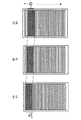
図1(A)と図2(A)は、タッチセンサ部の等価回路図、図1(B)と図2(B)は、タッチセンサ部の構造図(概略断面図)である。ここで図1は、被検出物としての指がセンサに近接していない場合、図2がセンサに近接または接触している場合をそれぞれ示す。
First, as a matter common to the four embodiments, the basics of touch detection in the display device of the present embodiment will be described with reference to FIGS.
1A and 2A are equivalent circuit diagrams of the touch sensor unit, and FIGS. 1B and 2B are structural diagrams (schematic cross-sectional views) of the touch sensor unit. Here, FIG. 1 shows a case where a finger as an object to be detected is not close to the sensor, and FIG. 2 is a case where the finger is close to or in contact with the sensor.
図解するタッチセンサ部は、静電容量型タッチセンサであり、図1(B)および図2(B)に示すように容量素子からなる。具体的に、誘電体Dと、誘電体Dを挟んで対向配置する1対の電極、すなわち駆動電極E1および検出電極E2とから容量素子(静電容量)C1が形成されている。
図1(A)および図2(A)に示すように、容量素子C1は、駆動電極E1がACパルス信号Sgを発生する交流信号源Sに接続され、検出電極E2が電圧検出器DETに接続される。このとき検出電極E2は抵抗Rを介して接地されることで、DCレベルが電気的に固定される。
The illustrated touch sensor unit is a capacitive touch sensor and includes a capacitive element as shown in FIGS. 1 (B) and 2 (B). Specifically, a capacitive element (capacitance) C1 is formed from the dielectric D and a pair of electrodes disposed opposite to each other with the dielectric D interposed therebetween, that is, the drive electrode E1 and the detection electrode E2.
As shown in FIGS. 1A and 2A, the capacitive element C1 has a drive electrode E1 connected to an AC signal source S that generates an AC pulse signal Sg, and a detection electrode E2 connected to a voltage detector DET. Is done. At this time, the detection electrode E2 is grounded via the resistor R, so that the DC level is electrically fixed.
交流信号源Sから駆動電極E1に所定の周波数、例えば数[kHz]〜十数[kHz]程度のACパルス信号Sgを印加する。このACパルス信号Sgの波形図を図3(B)に例示する。
すると検出電極E2に、図3(A)に示すような出力波形(検出信号Vdet)が現れる。
なお、詳細は後述するが、本発明の実施形態では、駆動電極E1が液晶駆動のための対向電極(画素電極に対向する、複数画素で共通の電極)に相当する。ここで対向電極は液晶駆動のため、いわゆるVcom反転駆動と称される交流駆動がなされる。よって、本発明の実施形態では、Vcom反転駆動のためのコモン駆動信号Vcomを、駆動電極E1をタッチセンサのために駆動するACパルス信号Sgとしても用いる。
An AC pulse signal Sg having a predetermined frequency, for example, about several [kHz] to several tens [kHz] is applied from the AC signal source S to the drive electrode E1. A waveform diagram of the AC pulse signal Sg is illustrated in FIG.
Then, an output waveform (detection signal Vdet) as shown in FIG. 3A appears on the detection electrode E2.
Although details will be described later, in the embodiment of the present invention, the drive electrode E1 corresponds to a counter electrode for driving liquid crystal (an electrode common to a plurality of pixels facing the pixel electrode). Here, since the counter electrode is driven by liquid crystal, AC driving called so-called Vcom inversion driving is performed. Therefore, in the embodiment of the present invention, the common drive signal Vcom for Vcom inversion drive is also used as the AC pulse signal Sg for driving the drive electrode E1 for the touch sensor.
指を接触していない図1に示す状態では、容量素子C1の駆動電極E1が交流駆動され、その充放電にともなって検出電極E2に交流の検出信号Vdetが出現する。以下、このときの検出信号を「初期検出信号Vdet0」と表記する。検出電極E2側はDC接地されているが高周波的には接地されていないため交流の放電経路がなく、初期検出信号Vdet0のパルス波高値は比較的大きい。ただし、ACパルス信号Sgが立ち上がってから時間が経過すると、初期検出信号Vdet0のパルス波高値が損失のため徐々に低下している。図3(C)に、スケールとともに波形を拡大して示す。初期検出信号Vdet0のパルス波高値は、初期値の2.8[V]から高周波ロスによって僅かな時間の経過で0.5[V]ほど、低下している。 In the state shown in FIG. 1 in which no finger is in contact, the drive electrode E1 of the capacitive element C1 is AC driven, and an AC detection signal Vdet appears on the detection electrode E2 along with the charge / discharge. Hereinafter, the detection signal at this time is expressed as “initial detection signal Vdet0”. Although the detection electrode E2 side is DC-grounded but not grounded in terms of high frequency, there is no AC discharge path, and the pulse height value of the initial detection signal Vdet0 is relatively large. However, when time elapses after the AC pulse signal Sg rises, the pulse peak value of the initial detection signal Vdet0 gradually decreases due to loss. FIG. 3C shows an enlarged waveform together with the scale. The pulse peak value of the initial detection signal Vdet0 is lowered by 0.5 [V] after a short time from the initial value of 2.8 [V] due to high frequency loss.
この初期状態から、指が検出電極E2に接触、または、影響を及ぼす至近距離まで接近すると、図2(A)に示すように、検出電極E2に容量素子C2が接続された場合と等価な状態に回路状態が変化する。これは、高周波的に人体が、片側が接地された容量と等価になるからである。
この接触状態では、容量素子C1とC2を介した交流信号の放電経路が形成される。よって、容量素子C1とC2の充放電に伴って、容量素子C1,C2に、それぞれ交流電流I1,I2が流れる。そのため、初期検出信号Vdet0は、容量素子C1とC2の比等で決まる値に分圧され、パルス波高値が低下する。
From this initial state, when the finger touches the detection electrode E2 or approaches a close distance that affects the state, as shown in FIG. 2A, a state equivalent to the case where the capacitive element C2 is connected to the detection electrode E2 The circuit state changes. This is because the human body is equivalent to a capacitor grounded on one side in terms of high frequency.
In this contact state, an AC signal discharge path is formed via the capacitive elements C1 and C2. Therefore, alternating currents I1 and I2 flow through the capacitive elements C1 and C2, respectively, as the capacitive elements C1 and C2 are charged and discharged. Therefore, the initial detection signal Vdet0 is divided to a value determined by the ratio of the capacitive elements C1 and C2, and the pulse peak value decreases.
図3(A)および図3(C)に示す検出信号Vdet1は、この指が接触したときに検出電極E2に出現する検出信号である。図3(C)から、検出信号の低下量は0.5[V]〜0.8[V]程度であることが分かる。
図1および図2に示す電圧検出器DETは、この検出信号の低下を、例えば閾値Vthを用いて検出することにより、指の接触を検出する。
The detection signal Vdet1 shown in FIGS. 3A and 3C is a detection signal that appears on the detection electrode E2 when this finger comes into contact. It can be seen from FIG. 3C that the amount of decrease in the detection signal is about 0.5 [V] to 0.8 [V].
The voltage detector DET shown in FIGS. 1 and 2 detects the contact of the finger by detecting the decrease in the detection signal using, for example, the threshold value Vth.
以下、より詳細な実施形態を、表示装置の構成と動作により説明する。 Hereinafter, more detailed embodiments will be described based on the configuration and operation of the display device.
《第1実施形態》
図4(A)〜図4(C)に、本実施形態に関わる表示装置の電極と、その駆動や検出のための回路の配置に特化した平面図を示す。また、図4(D)に、本実施形態に関わる表示装置の概略的な断面構造を示す。図4(D)は、例えば行方向(画素表示ライン方向)の6画素分の断面を表している。図5は、画素の等価回路図である。
図4に図解する表示装置は、「表示機能層」としての液晶層を備える液晶表示装置である。
<< First Embodiment >>
4A to 4C are plan views specialized in the arrangement of the electrodes of the display device according to the present embodiment and circuits for driving and detecting the electrodes. FIG. 4D shows a schematic cross-sectional structure of the display device according to this embodiment. FIG. 4D shows a cross section for six pixels in the row direction (pixel display line direction), for example. FIG. 5 is an equivalent circuit diagram of the pixel.
The display device illustrated in FIG. 4 is a liquid crystal display device including a liquid crystal layer as a “display function layer”.
液晶表示装置は、前述したように、液晶層を挟んで対抗する2つの画素のうち、複数の画素で共通な電極であり、各画素ごとに階調表示のための信号電圧に対し基準電圧を付与するコモン駆動信号Vcomが印加される電極(対向電極)を有する。本発明の実施形態では、この対向電極をセンサ駆動のための電極としても用いる。
図4(D)では断面構造を見易くするために、この本発明の主要な構成である、対向電極、画素電極および検出電極についてはハッチングを付すが、それ以外の部分(基板、絶縁膜および機能膜等)についてはハッチングを省略している。このハッチングの省略は、これ以降の他の断面構造図においても同様である。
As described above, the liquid crystal display device is an electrode common to a plurality of pixels among the two pixels facing each other with the liquid crystal layer interposed therebetween, and a reference voltage is applied to the signal voltage for gradation display for each pixel. It has an electrode (counter electrode) to which a common drive signal Vcom to be applied is applied. In the embodiment of the present invention, this counter electrode is also used as an electrode for driving the sensor.
In FIG. 4D, in order to make the cross-sectional structure easy to see, the counter electrode, the pixel electrode, and the detection electrode, which are the main components of the present invention, are hatched, but other parts (substrate, insulating film and function) The hatching of the film etc. is omitted. The omission of the hatching is the same in the other cross-sectional structural drawings thereafter.
液晶表示装置1は、図5に示す画素PIXがマトリクス配置されている。
各画素PIXは、図5に示すように、画素のセレクト素子としての薄膜トランジスタ(TFT;thin film transistor、以下、TFT23と表記)と、液晶層6の等価容量C6と、保持容量(付加容量ともいう)Cxとを有する。液晶層6を表す等価容量C6の一方側の電極は、画素ごとに分離されてマトリクス配置された画素電極22であり、他方側の電極は複数の画素で共通な対向電極43である。
In the liquid
As shown in FIG. 5, each pixel PIX includes a thin film transistor (TFT; thin film transistor, hereinafter referred to as TFT 23) as a pixel select element, an equivalent capacitance C6 of the
TFT23のソースとドレインの一方に画素電極22が接続され、TFT23のソースとドレインの他方に信号線SIGが接続されている。信号線SIGは不図示の垂直駆動回路(後述の実施形態に関わる図14参照)に接続され、信号電圧を持つ映像信号が信号線SIGに垂直駆動回路から供給される。
対向電極43には、コモン駆動信号Vcomが与えられる。コモン駆動信号Vcomは、中心電位を基準として正と負の電位を、1水平期間(1H)ごとに反転した信号である。
TFT23のゲートは行方向、即ち表示画面の横方向に並ぶ全ての画素PIXで電気的に共通化され、これにより走査線SCNが形成されている。走査線SCNは、不図示の垂直駆動回路から出力され、TFT23のゲートを開閉するためのゲートパルスが供給される。そのため走査線SCNはゲート線とも称させる。
The
A common drive signal Vcom is given to the
The gate of the
図5に示すように、保持容量Cxが等価容量C6と並列に接続されている。保持容量Cxは、等価容量C6では蓄積容量が不足し、TFT23のリーク電流などによって書き込み電位が低下するのを防止するために設けられている。また、保持容量Cxの追加はフリッカ防止や画面輝度の一様性向上にも役立っている。
As shown in FIG. 5, the holding capacitor Cx is connected in parallel with the equivalent capacitor C6. The storage capacitor Cx is provided in order to prevent the write capacitor from being lowered due to a leakage current of the
このような画素が配置された液晶表示装置1は、断面構造(図4(D))で見ると、断面に現れない箇所で図5に示すTFT23が形成され画素の駆動信号(信号電圧)が供給される基板(以下、駆動基板2という)と、駆動基板2に対向して配置された対向基板4と、駆動基板2と対向基板4との間に配置された液晶層6とを備えている。
In the liquid
駆動基板2は、図5のTFT23が形成された回路基板としてのTFT基板21(基板ボディ部はガラス等からなる)と、このTFT基板21上にマトリクス配置された複数の画素電極22とを有する。
TFT基板21に、各画素電極22を駆動するための図示しない表示ドライバ(垂直駆動回路、水平駆動回路等)が形成されている。また、TFT基板21に、図5に示すTFT23、ならびに、信号線SIGおよび走査線SCN等の配線が形成されている。TFT基板21に、後述するタッチ検出動作を行う検出回路(図6)が形成されていてもよい。
The
A display driver (vertical drive circuit, horizontal drive circuit, etc.) (not shown) for driving each
対向基板4は、ガラス基板41と、このガラス基板41の一方の面に形成されたカラーフィルタ42と、カラーフィルタ42の上(液晶層6側)に形成された対向電極43とを有する。カラーフィルタ42は、例えば赤(R)、緑(G)、青(B)の3色のカラーフィルタ層を周期的に配列して構成したもので、画素PIX(画素電極22)ごとにR、G、Bの3色の1色が対応付けられている。なお、1色が対応付けられている画素をサブ画素といい、R、G、Bの3色のサブ画素を画素という場合があるが、ここではサブ画素も画素PIXと表記する。
対向電極43は、タッチ検出動作を行うタッチセンサの一部を構成するセンサ駆動電極としても兼用されるものであり、図1および図2における駆動電極E1に相当する。
The
The
対向電極43は、コンタクト導電柱7によってTFT基板21と連結されている。このコンタクト導電柱7を介して、TFT基板21から対向電極43に交流パルス波形のコモン駆動信号Vcomが印加されるようになっている。このコモン駆動信号Vcomは、図1および図2の駆動信号源Sから供給されるACパルス信号Sgに相当する。
The
ガラス基板41の他方の面(表示面側)には、検出電極44が形成され、さらに、検出電極44の上には、保護層45が形成されている。検出電極44は、タッチセンサの一部を構成するもので、図1および図2における検出電極E2に相当する。ガラス基板41に、後述するタッチ検出動作を行う検出回路(図6)が形成されていてもよい。
A
液晶層6は、「表示機能層」として、印加される電界の状態に応じて厚さ方向(電極の対向方向)を通過する光を変調する。液晶層6は、例えば、TN(ツイステッドネマティック)、VA(垂直配向)、ECB(電界制御複屈折)等の各種モードの液晶材料が用いられる。
The
なお、液晶層6と駆動基板2との間、および液晶層6と対向基板4との間には、それぞれ配向膜が配設される。また、駆動基板2の反表示面側(即ち背面側)と対向基板4の表示面側には、それぞれ偏光板が配置される。これらの光学機能層は、図4で図示を省略している。
An alignment film is provided between the
対向電極43は、図4(A)に示すように、画素配列の行または列、本例では列の方向(図の縦方向)に分割されている。この分割の方向は、表示駆動における画素ラインの走査方向、すなわち不図示の垂直駆動回路が走査線SCNを順次活性化していく方向と対応する。
対向電極43は、合計でn個に分割されている。よって、対向電極43_1,43_2,…,43_m,…,43_nは、行方向に長い帯状のパターンを有して面状配置され、当該面内で互いの離間距離をとって平行に敷き詰められている。
As shown in FIG. 4A, the
The
n分割された対向電極43_1〜43_nは、少なくとも2以上のm(<n)本で同時に駆動される。つまり、m本の対向電極43_1〜43_mに同時にコモン駆動信号Vcomが印加されて、その電位が反転を1水平期間(1H)ごとに繰り返す。そのとき、他の対向電極は、駆動信号が与えられないため電位変動しない。本発明の実施形態では、この同時駆動される対向電極の束を、交流駆動電極ユニットEUと表記する。
本発明の実施形態では、交流駆動電極ユニットEUごとに対向電極の数は一定の数mとする。また、交流駆動電極ユニットEUが、その束ねる対向電極の組み合わせを変えながら列方位にステップ状にシフトする。つまり、シフトごとに交流駆動電極ユニットEUとして選択される対向電極の組み合わせが変化する。そして、2回のシフトでは1つの、分割された対向電極のみが選択から外れ、代わりに、分割された対向電極が新たに選択される。
The counter electrodes 43_1 to 43_n divided into n are simultaneously driven with at least two (m) (<n). That is, the common drive signal Vcom is simultaneously applied to the m counter electrodes 43_1 to 43_m, and the potential is inverted every one horizontal period (1H). At that time, the other counter electrodes do not change in potential because no drive signal is supplied thereto. In the embodiment of the present invention, the bundle of counter electrodes that are simultaneously driven is referred to as an AC drive electrode unit EU.
In the embodiment of the present invention, the number of counter electrodes for each AC drive electrode unit EU is a fixed number m. Further, the AC drive electrode unit EU shifts stepwise in the column direction while changing the combination of the counter electrodes bundled together. That is, the combination of the counter electrodes selected as the AC drive electrode unit EU changes for each shift. In the two shifts, only one divided counter electrode is excluded from the selection, and instead, the divided counter electrode is newly selected.
このシフト動作を言い換えると、「n個の対向電極43_1〜43_nは、列方向において画素電極22と同じ数(つまり画素数)だけ等間隔に配置され、Vcom交流駆動を繰り返す際に、1つの交流駆動電極ユニットEUとして選択するm(<n)個の対向電極の組み合わせを、列方向内で対向電極43_1〜43_nが配置されたピッチを単位にシフトする。ここで「対向電極のピッチ」とは、列方向の対向電極の幅と、その幅方向の片側に隣接する他の対向電極までの離間距離との合計した距離である。通常、列方向における対向電極のピッチは、列方向における画素サイズに等しい。 In other words, “the n counter electrodes 43_1 to 43_n are arranged at equal intervals in the column direction by the same number as the pixel electrodes 22 (that is, the number of pixels). The combination of m (<n) counter electrodes selected as the drive electrode unit EU is shifted in units of the pitch in which the counter electrodes 43_1 to 43_n are arranged in the column direction. The total distance of the width of the counter electrode in the column direction and the separation distance to another counter electrode adjacent to one side in the width direction. Usually, the pitch of the counter electrodes in the column direction is equal to the pixel size in the column direction.
このような対向電極の交流駆動電極ユニットEUを単位とするVcom駆動と、そのシフト動作は、不図示の垂直駆動回路(書き込み駆動走査部)内に設けられた、「交流駆動走査部」としてのVcom駆動回路9により行われる。Vcom駆動回路9の動作は、「m本の対向電極の配線を同時にVcom交流駆動する交流信号源S(図1および図2参照)を列方向に移動して、選択する対向電極を1つずつ変えながら列方向に走査する動作」に等しいとみなせる。
Such a Vcom drive using the AC drive electrode unit EU of the counter electrode as a unit and a shift operation thereof as an “AC drive scan unit” provided in a vertical drive circuit (write drive scan unit) (not shown). This is performed by the
一方、検出電極44は、対向電極43の電極パターン(対向電極43_1〜43_n)の分離方向に延びる複数のストライプ状の電極パターン(検出電極44_1〜44_k)から構成されている。k個の検出電極44_1〜44_kから、それぞれ検出信号Vdetが出力される。これらk個の検出信号Vdetが、図1および図2に示す電圧検出器DETを基本検出単位とする、「検出部」としての検出回路8に入力されるようになっている。
On the other hand, the
なお、図4(A)と図4(B)は電極パターン説明のために分けた図であるが、実際には、図4(C)のように対向電極43_1〜43_nと検出電極44_1〜44_kとは重ねて配置され、2次元平面内の位置検出が可能になっている。
この構成によって、検出回路8は、どの電圧検出器DETに電圧変化が生じたかで行方向の位置が検出でき、その検出時のタイミングによって列方向の位置情報を得ることができる。つまり、Vcom駆動回路9のVcom駆動と検出回路8の動作が、例えば所定周期のクロック信号で同期しているとする。このような同期動作によって、検出回路8が電圧変化を得たときが、Vcom駆動回路9が分割された、どの対向電極を駆動していたときに対応するかが分かるため、指の接触位置中心を検出できる。このような検出動作は、液晶表示装置1全体を統括する不図示のコンピュータベースの統括制御回路、例えばCPUやマイクロコンピュータ、あるいは、タッチ検出のための制御回路により制御される。
Note that FIGS. 4A and 4B are separated views for explaining electrode patterns, but in actuality, the counter electrodes 43_1 to 43_n and the detection electrodes 44_1 to 44_k as shown in FIG. 4C. Are arranged in an overlapping manner, and position detection in a two-dimensional plane is possible.
With this configuration, the
図6は、タッチ検出動作を行う検出回路8の一構成例を、検出対象の位置を示す電極パターンとともに示す図である。
図6に示すように、斜線により示す対向電極43_1が交流信号源Sに接続されて選択され、それ以外の対向電極43_2〜43_5がVcom反転駆動の中心電位を与えるGND電位で保持されている。前者の対向電極が選択された状態をオン、非選択の状態をオフともいう。
図6は、これらの対向電極群に交差する、ある検出電極44に接続された電圧検出器DETと、交流信号源Sの回路図を示している。検出電極44と各対向電極との各交差部分に、(静電)容量素子C1_1〜C1_5が形成される。なお、本実施形態では実際には、前述したようにm個の対向電極からなる交流駆動電極ユニットEU1つが同時に交流駆動される。よって、図6に示す1つの対向電極(例えば、43_1の1つ)が、図4の交流駆動電極ユニットEUに対応するとみなしてよい。
FIG. 6 is a diagram illustrating a configuration example of the
As shown in FIG. 6, the counter electrode 43_1 indicated by hatching is selected by being connected to the AC signal source S, and the other counter electrodes 43_2 to 43_5 are held at the GND potential that provides the center potential of the Vcom inversion drive. The former state in which the counter electrode is selected is also referred to as on, and the non-selected state is also referred to as off.
FIG. 6 shows a circuit diagram of a voltage detector DET connected to a
図6に図解する交流信号源Sは、制御部91と、2つのスイッチSW(+),SW(-)と、ラッチ回路92と、バッファ回路(波形整形部)93と、出力スイッチSWを有する。
制御部91は、プラス電圧V(+)とマイナス電圧V(-)を各々がスイッチする2つのスイッチSW(+),SW(-)を制御する回路である。制御部91は、交流信号源S内に設けなくとも、外部のCPU等で代用できる。
スイッチSW(+)はプラス電圧V(+)とラッチ回路92の入力との間に接続され、スイッチSW(-)はマイナス電圧V(-)とラッチ回路92の入力との間に接続されている。ラッチ回路92の出力はバッファ回路93を介して、出力スイッチSWのオン側ノードに接続されている。バッファ回路93はプラス電圧V(+)とマイナス電圧V(-)に、入力電位を電位補償して出力する回路である。
ここで出力スイッチSWは、制御部91により制御されて、当該交流信号源Sをオン(選択状態あるいは活性状態)とするか、非活性のGND接続とするかを制御する。この制御部91の機能は他の交流信号源Sとの制御と同期させる関係上、通常は、たとえば活性化する交流信号源Sのグループをシフトして選択する信号を、シフトレジスタ等で順送りする等の構成によって実施される。
The AC signal source S illustrated in FIG. 6 includes a
The
The switch SW (+) is connected between the positive voltage V (+) and the input of the
Here, the output switch SW is controlled by the
(静電)容量素子C1_1〜C1_5が接続された検出電極44に、電圧検出器DETが接続されている。
図6に図解する電圧検出器DETは、OPアンプ回路81、整流回路82およびADコンバータ83から構成される。
OPアンプ回路81は、OPアンプ84、抵抗R1とR2、および、容量C3により図示のように構成され、ノイズ除去のためのフィルタ回路を形成する。このフィルタ回路は抵抗の比等で増幅率が決まり、信号増幅回路としても機能する。
OPアンプ84の非反転入力「+」に検出電極44が接続され、ここから検出信号Vdetが入力される。検出電極44は、その電位のDCレベルを電気的に固定するために抵抗Rを介して接地電位に接続されている。OPアンプ84の出力と反転入力「−」との間に抵抗R2と容量C3が並列接続され、OPアンプ84の反転入力「−」と接地電位との間に抵抗R1が接続されている。
整流回路82は、半波整流を行うダイオードD1と、充電キャパシタC4と、放電抵抗R0とを有する。ダイオードD1のアノードがOPアンプ回路81の出力に接続され、ダイオードD1のカソードと接地電位との間に、充電キャパシタC4と放電抵抗R0がそれぞれ接続されている。充電キャパシタC4と放電抵抗R0により平滑回路が形成される。
ダイオードD1のカソード(整流回路82の出力)電位が、ADコンバータ83を介してデジタル値として読み出される。図6に示すADコンバータ83は、閾値と電圧比較を実行するコンパレータ85のみ示すが、抵抗ラダー型や容量分割型などコンバータのタイプに依存して異なる構成は省略する。ADコンバータ83から出力されたデジタル値を、さらに不図示の比較器等によって所定の閾値Vth(図3(A)参照)と比較する。比較回路は、CPUなどの制御回路(不図示)の機能としても実現できるため、ここでは図示を省略している。この比較結果が、タッチされたか否かを示す信号、例えばボタン操作の有無を示す信号として各種アプリケーションに利用される。
A voltage detector DET is connected to the
The voltage detector DET illustrated in FIG. 6 includes an
The
The
The
The cathode (output of the rectifier circuit 82) potential of the diode D1 is read as a digital value via the
「交流駆動走査部」としてのVcom駆動回路9は、図4(D)の駆動基板2側に形成されるが、「検出部」としての検出回路8は、駆動基板2側でも対向基板4側でもよい。TFTが多く集積化されているため製造工程数を減らすには駆動基板2に検出回路8も一緒に形成することが望ましい。ただし、検出電極44が対向基板4側に存在し、検出電極44が透明電極材料から形成されるため配線抵抗が高くなることがある。そのような場合、配線抵抗が高いことの不具合を回避するには、対向基板4側に検出回路8を形成することが好ましい。ただし、検出回路8だけのために対向基板4にTFT形成プロセスを用いると、コスト高になるという不利益がある。
以上の利益と不利益を総合的に勘案して、検出回路8の形成位置を決定するとよい。
The
The formation position of the
つぎに、以上の交流信号源Sを基本構成とするVcom駆動回路9による、対向電極43のシフトおよび交流駆動について、図面を用いて説明する。
図7(A)に、画素表示ライン単位(書き込みユニットともいう)で分割された対向電極43_1〜43_nを示す。図7(B)に、そのうちの最初の1本である対向電極43_1の駆動時におけるタッチセンサ部の等価回路図を示す。
図7(A)に示すように対向電極43_1に交流信号源Sが接続されてVcom交流駆動されている。このときタッチセンサ部は、既に説明したように図7(B)のような等価回路が形成される。ただし、ここでは容量素子C1_1〜C1_nの各静電容量値を“Cp”、検出電極44に、容量素子C1_1〜C1_n以外に接続されている容量成分(寄生容量)を“Cc”、交流信号源Sによる交流電圧の実効値を“V1”と表す。
このとき電圧検出器DETで検出される検出信号Vdetは、指が非接触のときは電圧Vs、指が接触のときは電圧Vfとなる。以下、電圧Vs,Vfをセンサ電圧という。
Next, shifting of the
FIG. 7A illustrates the counter electrodes 43_1 to 43_n divided in pixel display line units (also referred to as writing units). FIG. 7B shows an equivalent circuit diagram of the touch sensor portion at the time of driving the counter electrode 43_1 which is the first one of them.
As shown in FIG. 7A, the AC signal source S is connected to the counter electrode 43_1 and is driven by Vcom AC. At this time, as described above, an equivalent circuit as shown in FIG. 7B is formed in the touch sensor unit. However, here, the capacitance values of the capacitive elements C1_1 to C1_n are “Cp”, the capacitive component (parasitic capacitance) connected to the
At this time, the detection signal Vdet detected by the voltage detector DET is the voltage Vs when the finger is not in contact and the voltage Vf when the finger is in contact. Hereinafter, the voltages Vs and Vf are referred to as sensor voltages.
非接触時のセンサ電圧Vsは、図7(C)のような式によって表される。この式から、対向電極43の分割数nが大きいと、その分、各静電容量値Cpは小さくなる。図7(C)の式の分母は“nCp”がほぼ一定なため余り大きな変化がないが、分子が小さくなる。よって、対向電極43の分割数nが大きくなるにしたがって、センサ電圧Vsの大きさ(交流の実効値)も小さくなる。
したがって、分割数nは余り大きくできない。
The sensor voltage Vs at the time of non-contact is represented by an equation as shown in FIG. From this equation, when the division number n of the
Therefore, the division number n cannot be increased too much.
一方、分割数nが小さく、1つの対向電極43_1の面積が大きいと、そのVcom交流駆動が電極間で切り替わる時の微妙な電位変動(過渡的な電位変動)が表示画面で線として見えてしまう。
そこで、本実施形態では前述したように、分割自体は画素表示ライン(書き込みユニット)ごとに行うが、複数の対向電極を同時にVcom交流駆動する。また、一部の分割された対向電極は、2回連続して選択する。これにより、分割数nが大きくなることによるセンサ電圧の低下(S/N比の低下)と、電極切り替わり時の電位変動の希釈化(目立たなくすること)とを同時に達成する。
On the other hand, if the division number n is small and the area of one counter electrode 43_1 is large, a subtle potential fluctuation (transient potential fluctuation) when the Vcom AC drive is switched between the electrodes appears as a line on the display screen. .
Therefore, as described above, in this embodiment, the division itself is performed for each pixel display line (writing unit), but a plurality of counter electrodes are simultaneously driven by Vcom AC. In addition, a part of the divided counter electrode is selected twice in succession. As a result, a decrease in sensor voltage (decrease in S / N ratio) due to an increase in the number of divisions n and a dilution in potential fluctuation (disappearance) at the time of electrode switching are achieved at the same time.
図8に、この交流駆動とシフトの動作説明図を示す。
図8において斜線により示す7本の対向電極により交流駆動電極ユニットEUが構成されている。図8(A)〜(C)は、交流駆動電極ユニットEUを1画素ライン単位で列方向にシフトさせたときの選択範囲の推移を示す。
図8(A)の時間T1では、最初の1つの書き込みユニットは非選択であるが、2番目から8番目のラインに対応した対向電極が選択されて同時に交流信号源Sで交流駆動されている。次のサイクル(時間T2)では、1つの書き込みユニット分シフトし、1番目と2番目のラインに対応する2つの対向電極が非選択、3番目以降の7本が選択、その他が非選択となっている。さらにその次のサイクル(時間T3)では、さらに1つの書き込みユニット分シフトし、1〜3番目のラインに対応する対向電極が非選択、4番目以降の7本が選択、その他が非選択となる。
以後、同様にシフトと交流駆動を繰り返す。
FIG. 8 is a diagram for explaining the operation of this AC drive and shift.
In FIG. 8, an AC drive electrode unit EU is constituted by seven counter electrodes indicated by hatching. FIGS. 8A to 8C show the transition of the selection range when the AC drive electrode unit EU is shifted in the column direction in units of one pixel line.
At time T1 in FIG. 8A, the first writing unit is not selected, but the counter electrode corresponding to the second to eighth lines is selected and simultaneously driven by the AC signal source S. . In the next cycle (time T2), the shift is performed by one writing unit, the two counter electrodes corresponding to the first and second lines are not selected, the seventh and subsequent electrodes are selected, and the others are not selected. ing. In the next cycle (time T3), the shift is further performed by one writing unit, the counter electrode corresponding to the first to third lines is not selected, the seventh and subsequent electrodes are selected, and the others are not selected. .
Thereafter, the shift and AC driving are repeated in the same manner.
以上の記載から、本実施形態に関わる表示装置の駆動方法は、「面状に行列配置された複数の画素電極22と、当該画素電極22と対向する面状に配置され、行列配置の行または列と平行な走査方向に分離されている複数の対向電極43と、の間に印加される電圧を制御して、画像の階調表現を行う表示駆動のステップと、互いに対向する複数の対向電極43と検出電極44との間に形成される静電容量C1の印加電圧(例えば、センサ電圧Vsに比例)が外部容量C2の影響で低下することを、表示駆動の最中に検出電極44側で検出するタッチ検出のステップと、を含む。そして、表示駆動およびタッチ検出のステップが、複数の対向電極43から、連続する2つ以上の対向電極を選択して当該選択した対向電極を交流駆動する交流駆動のステップと、交流駆動時に検出電極44側に伝達される交流電圧の大きさを測定し、当該測定の結果に基づいて外部容量C2の有無を判定する検出のステップと、連続する2回の交流駆動で共通な1つ以上の対向電極が選択されるように、対向電極の選択対象を走査方向内でシフトするシフトのステップと、を含む」ことの一例といえる。
From the above description, the driving method of the display device according to the present embodiment is described as follows: “A plurality of
この動作により、図7(C)に示した式におけるnの値は、実際の分割数の1/7に低減されてセンサ電圧Vsの実効値がその分、大きくなる。一方、図8に示すように、選択グループに新たに含まれ、それに変わって含まれなくなる単位が1画素ラインに対応する1つの対向電極である。よって、交流駆動の切り替わり周波数がコモン駆動信号Vcomの1H反転周波数と等しくなる。この周波数は商用電源周波数、例えば60[Hz]を列方向の画素数倍した非常に高い周波数となる。たとえば列方向の画素数が480の場合、この周波数は28.8[kHz]、パルス波形の周波数としては、その半分の14.4[kHz]となる。よって、交流駆動のシフトに起因する画像変化は、人の目に視認できない十分に高い周波数となる。
以上より、センサ電圧の低下によるS/N比低下の防止と、電極駆動の切り替えによる画質低下の防止が両立できる。
By this operation, the value of n in the equation shown in FIG. 7C is reduced to 1/7 of the actual number of divisions, and the effective value of the sensor voltage Vs increases accordingly. On the other hand, as shown in FIG. 8, a unit newly included in the selected group and not included in the selected group is one counter electrode corresponding to one pixel line. Therefore, the AC drive switching frequency becomes equal to the 1H inversion frequency of the common drive signal Vcom. This frequency is a very high frequency obtained by multiplying the commercial power supply frequency, for example, 60 [Hz] by the number of pixels in the column direction. For example, when the number of pixels in the column direction is 480, this frequency is 28.8 [kHz], and the frequency of the pulse waveform is 14.4 [kHz], which is half that frequency. Therefore, the image change due to the AC drive shift has a sufficiently high frequency that cannot be visually recognized by human eyes.
From the above, it is possible to both prevent the S / N ratio from decreasing due to a decrease in sensor voltage and prevent the image quality from decreasing due to switching of electrode driving.
次に、以上のような構成の表示装置の動作を説明する。 Next, the operation of the display device configured as described above will be described.
駆動基板2の表示ドライバ(図示しない水平駆動回路および垂直駆動回路等)は、対向電極43の各電極パターン(対向電極43_1〜43_n)に対してコモン駆動信号Vcomを線順次で供給する。このとき、対向電極の選択の仕方とシフトの仕方は、上述したとおりである。コモン駆動信号Vcomは、画像表示の対向電極電位制御のためにも用いられる。
また、表示ドライバは、信号線SIGを介して画素電極22へ信号電圧を供給すると共に、これに同期して、走査線SCNを介して各画素電極のTFTのスイッチングを線順次で制御する。これにより、液晶層6には、画素ごとに、コモン駆動信号Vcomと各画素信号とにより定まる縦方向(基板に垂直な方向)の電界が印加されて液晶状態の変調が行われる。このようにして、いわゆる反転駆動による表示が行われる。
A display driver (such as a horizontal drive circuit and a vertical drive circuit (not shown)) of the
Further, the display driver supplies a signal voltage to the
一方、対向基板4の側では、対向電極43の各電極パターン(対向電極43_1〜43_n)と、検出電極44の各電極パターン(検出電極44_1〜44_k)との交差部分にそれぞれ容量素子C1が形成される。対向電極43の各電極パターンにコモン駆動信号Vcomを時分割的に順次印加していくと、その印加された対向電極43の電極パターンと検出電極44の各電極パターンとの交差部分に形成されている一列分の容量素子C1の各々に対する充放電が行われる。その結果、容量素子C1の容量値に応じた大きさの検出信号Vdetが、検出電極44の各電極パターンからそれぞれ出力される。対向基板4の表面にユーザの指が触れられていない状態においては、この検出信号Vdetの大きさはほぼ一定(センサ電圧Vs)となる。コモン駆動信号Vcomのスキャンに伴い、充放電の対象となる容量素子C1の列が線順次的に移動していく。
On the other hand, on the
ここで、対向基板4の表面のいずれかの場所にユーザの指が触れると、そのタッチ箇所に元々形成されている容量素子C1に、指による容量素子C2が付加される。その結果、そのタッチ箇所がスキャンされた時点(すなわち、対向電極43の電極パターンのうち、そのタッチ箇所に対応する電極パターンにコモン駆動信号Vcomが印加されたとき)の検出信号Vdetの値(センサ電圧Vs)が他の箇所よりも小さくなる(センサ電圧Vf(<Vs)となる)。検出回路8(図6)は、この検出信号Vdetを閾値電圧Vthと比較して、閾値電圧Vth以下の場合に、その箇所をタッチ箇所として判定する。このタッチ箇所は、コモン駆動信号Vcomの印加タイミングと、閾値電圧Vth以下の検出信号Vdetの検出タイミングとから求めることができる。
Here, when a user's finger touches any location on the surface of the
このように、本実施形態によれば、液晶表示素子に元々備えられている液晶駆動の共通電極(対向電極43)を、駆動電極と検出電極とからなる一対のタッチセンサ用電極のうちの一方として兼用すると共に、表示駆動信号としてのコモン駆動信号Vcomを、タッチセンサ駆動信号として共用するようにして静電容量型タッチセンサを構成している。よって、新たに設ける電極は検出電極44だけでよく、また、タッチセンサ駆動信号を新たに用意する必要がない。したがって、構成が簡単である。
また、複数の対向電極を同時に交流駆動し、その同時に交流駆動する電極グループを、各対向電極が2回の交流駆動で共に選択されるようにシフトする。このため、センサの検出電圧のS/N比低下と画質低下の防止を両立できる。
さらにコモン駆動信号Vcomの駆動電極と駆動回路を、センサ駆動電極と駆動回路と兼用できるため、その分の配置スペースと消費電力の節約ができる。
Thus, according to this embodiment, the liquid crystal driving common electrode (counter electrode 43) originally provided in the liquid crystal display element is used as one of a pair of touch sensor electrodes including the driving electrode and the detection electrode. And the common drive signal Vcom as the display drive signal is shared as the touch sensor drive signal to configure the capacitive touch sensor. Therefore, only the
Further, the plurality of counter electrodes are simultaneously AC driven, and the electrode groups that are simultaneously AC driven are shifted so that each counter electrode is selected together by two AC drives. For this reason, it is possible to achieve both reduction in the S / N ratio of the detection voltage of the sensor and prevention of deterioration in image quality.
Furthermore, since the drive electrode and the drive circuit for the common drive signal Vcom can be used as the sensor drive electrode and the drive circuit, the arrangement space and power consumption can be saved accordingly.
なお、図4および図6において、検出電極44は細い幅のラインとして示すが、行方向に大きな幅に形成してもよい。この幅は、容量素子C1の容量値が小さ過ぎて、より大きくしたい場合に、電極幅を大きく対処できる。逆に、例えば誘電体Dが薄いために容量素子C1の容量値が大き過ぎて、より小さくしたい場合は、電極幅を小さくして対処できる。
あるいは、検出電極44を列方向に分割して、それぞれの分割した孤立パターンから配線を列方向に引き出してもよい。それぞれの配線に電圧検出器DETを接続してもよいが、回路規模が増大することを防止するために複数の検出電極44で1つの電圧検出器DETを共用してもよい。例えば、1つの電圧検出器DETを1列の検出電極44で共用し、当該電圧検出器DETによって、時分割で検出電極44ごとの検出を行ってもよい。
4 and 6, the
Alternatively, the
<変形例1>
第1実施形態では、分割された対向電極の1ピッチごとに、同時駆動する対向電極グループ(交流駆動電極ユニットEU)をシフトしたが、これに限定されない。
たとえば、対向電極の2ピッチ、3ピッチ、または、それ以上の単位で交流駆動電極ユニットEUをシフト動作してもよい。ただし、1回のシフト動作に対応する上記ピッチ数が増えると、画素の切り替えが見えやすくなるので、事実上の限界はある。ただし、1回のシフト動作に対応する上記ピッチ数を増やしていったときに、どの段階で画質に影響するかは、電位変動を起こす配線に接続されている容量の大きさなどが違うと異なるので、一律には決められない。
また、交流駆動電極ユニットEUに含まれる分割された対向電極43の数は、2以上なら任意である。ただし、あまり、この数を大きくすると分割しシフトする意味が薄れ、また、センサの列方向の分解能が低下する。さらに、表示制御やセンサ駆動にとって無駄なVcom駆動領域が増えるため、無駄な電力消費が増大する。これらをすべて勘案して、交流駆動電極ユニットEUに含まれる分割された対向電極43の数の上限や最適値が決められる。
<
In the first embodiment, the counter electrode group (AC drive electrode unit EU) that is driven simultaneously is shifted for each pitch of the divided counter electrodes. However, the present invention is not limited to this.
For example, the AC drive electrode unit EU may be shifted in units of 2 pitches, 3 pitches or more of the counter electrodes. However, as the number of pitches corresponding to one shift operation increases, pixel switching becomes easier to see, so there is a practical limit. However, when the number of pitches corresponding to one shift operation is increased, the stage at which the image quality is affected differs depending on the size of the capacitor connected to the wiring causing the potential fluctuation. So it cannot be decided uniformly.
Further, the number of divided
いずれにしても、この変形例1は、「複数の対向電極は、走査方向において2以上の所定数の画素電極ごとに1つの割合で等間隔に配置され、駆動検出部は、交流駆動を繰り返す際に、選択する対向電極の組み合わせを、走査方向内で前記対向電極が配置されたピッチを単位にシフトする」ことの一例といえる。
なお、この変形例1は、後述する第2実施形態、第4実施形態でも適用できる。
また、検出電極44は複数k個、設けたが、列方向にのみタッチ検出する場合は、検出電極44は1つで構わない。本発明の実施形態は、タッチ位置をマトリクス検出できる構成例を示すものである。
In any case, the first modification is as follows: “The plurality of counter electrodes are arranged at equal intervals at a rate of one every two or more predetermined number of pixel electrodes in the scanning direction, and the drive detection unit repeats AC driving. In this case, it can be said that the combination of the counter electrodes to be selected is shifted in units of the pitch at which the counter electrodes are arranged in the scanning direction.
The first modification can also be applied to second and fourth embodiments described later.
Further, although a plurality k of
<変形例2>
図9に、第1実施形態における変形例(変形例2)を示す。
変形例2では、断面構造内において検出電極44を、カラーフィルタ42を挟んで対向電極43と対抗する位置に形成している。これにより容量素子C1が大きくなるが、表示面から検出電極44までの距離が遠くなるため指の接近による影響(容量C2)が小さくなる。しかし、指の大きさは画素に比べて大きいので、容量C2は低下しても、容量素子C1との関係でその低下の影響が軽微な場合もある。あるいは、逆に感度が高くなる場合もある。よって、図9のような構造が採用できる。図9に示す構造においても、検出電極44の幅で容量素子C1の大きさが調整できる。
<
FIG. 9 shows a modification (Modification 2) in the first embodiment.
In the second modification, the
《第2実施形態》
次に、第2実施形態について説明する。本実施形態は、上記第1実施形態の場合とは異なり、表示素子として横電界モードの液晶素子を用いるようにしたものである。
<< Second Embodiment >>
Next, a second embodiment will be described. Unlike the case of the first embodiment, the present embodiment uses a horizontal electric field mode liquid crystal element as a display element.
図10は、本実施形態の表示装置の概略的な断面構造図である。図10で、第1実施形態と同一の構成は、同一の符号を付し、適宜説明を省略する。 FIG. 10 is a schematic cross-sectional structure diagram of the display device of the present embodiment. In FIG. 10, the same components as those in the first embodiment are denoted by the same reference numerals, and description thereof will be omitted as appropriate.
本実施形態の表示装置が、電極の位置に限り(パターンは異なる)、第1野実施形態と異なる点は、対向電極43を駆動基板2側に配置することである。本実施形態における対向電極43は、画素電極22の反液晶層6側に画素電極22と対向して配置されている。ここで対向といっても、特に図示しないが、画素電極22同士の間の距離が比較的大きく取られ、画素電極22の間から対向電極43が液晶層6に電界を作用させる。つまり、液晶層6に対する電界の作用する方向が横方向の横電界モードの液晶表示となる。
その他の構成は、断面における配置に限れば、第1実施形態と第2実施形態は同じとなる。
The display device of this embodiment is different from the first embodiment only in the position of the electrode (the pattern is different). The
Other configurations are the same in the first embodiment and the second embodiment as long as the arrangement in the cross section is limited.
容量素子C1は、検出電極44と対向電極43との間に形成されるため、第1実施形態(図4(D))に比べると、容量値が低くなる。しかし、電極間隔が遠くなることを、電極幅を大きくするなどで補うような対処が可能であり、また、容量素子C2との関係で感度が大きくなる場合もある。
Since the capacitive element C1 is formed between the
液晶層6は、電界の状態に応じてそこを通過する光を変調するものであり、例えば、FFS(フリンジフィールドスイッチング)モードや、IPS(インプレーンスイッチング)モード等の横電界モードの液晶が用いられる。
The
つぎに、図11を参照して、より詳細に説明する。
図11に示すFFSモードの液晶素子においては、駆動基板2上に形成された対向電極43の上に、絶縁層25を介して、櫛歯状にパターニングされた画素電極22が配置され、これを覆うように配向膜26が形成される。この配向膜26と、対向基板4側の配向膜46との間に、液晶層6が挟持される。2枚の偏光板24,45は、クロスニコルの状態で配置される。2枚の配向膜26,46のラビング方向は、2枚の偏光板24,45の一方の透過軸と一致している。図10では、ラビング方向が出射側の保護層45の透過軸と一致している場合を図示してある。さらに、2枚の配向膜26,46のラビング方向および保護層45の透過軸の方向は、液晶分子が回転する方向が規定される範囲で、画素電極22の延設方向(櫛歯の長手方向)とほぼ平行に設定されている。
Next, a more detailed description will be given with reference to FIG.
In the FFS mode liquid crystal element shown in FIG. 11, the
次に、以上のような構成の表示装置の動作を説明する。 Next, the operation of the display device configured as described above will be described.
ここではまず、図11および図12を参照して、FFSモードの液晶素子の表示動作原理について簡単に説明する。ここで、図12は液晶素子の要部断面を拡大して表したものである。これらの図で、(A)は電界非印加時、(B)は電界印加時における液晶素子の状態を示す。 Here, first, the principle of display operation of the FFS mode liquid crystal element will be briefly described with reference to FIGS. Here, FIG. 12 is an enlarged view of a cross section of a main part of the liquid crystal element. In these figures, (A) shows the state of the liquid crystal element when no electric field is applied, and (B) shows the state of the liquid crystal element when the electric field is applied.
対向電極43と画素電極22との間に電圧を印加していない状態では(図11(A)、図12(A))、液晶層6を構成する液晶分子61の軸が入射側の偏光板24の透過軸と直交し、かつ、出射側の保護層45の透過軸と平行な状態となる。このため、入射側の偏光板24を透過した入射光hは、液晶層6内において位相差を生じることなく出射側の保護層45に達し、ここで吸収されるため、黒表示となる。一方、対向電極43と画素電極22との間に電圧を印加した状態では(図11(B)、図12(B))、液晶分子61の配向方向が、画素電極間に生じる横電界Eにより、画素電極22の延設方向に対して斜め方向に回転する。この際、液晶層6の厚み方向の中央に位置する液晶分子61が約45度回転するように白表示時の電界強度を最適化する。これにより、入射側の偏光板24を透過した入射光hには、液晶層6内を透過する間に位相差が生じ、90度回転した直線偏光となり、出射側の保護層45を通過するため、白表示となる。
In a state where no voltage is applied between the
なお、タッチセンサ部に関しては、断面構造内の電極配置が異なるのみで、基本的な動作は第1実施形態と共通する。つまり、Vcom交流駆動とシフトの繰り返しにより対向電極43を列方向で駆動し、そのときのセンサ電圧VsとVfの差を、電圧検出器DETを介して読み取る。デジタル値として読み取ったセンサ電圧vを、閾値電圧Vthを用いて比較し、指の接触または接近の位置をマトリクス状に検出する。
このとき、第1実施形態と同様に、図8に示すように、m本(図8ではm=7)同時に対向電極43を交流駆動し、1つの書き込みユニットに対応する1本の対向電極43ずつずらしてシフトしてから再度交流駆動を行い、このシフトと交流駆動を繰り返す。このため、図7(C)に示した式におけるnの値は、実際の分割数の1/mに低減されてセンサ電圧Vsがその分、大きくなる。一方、図8に示すように、選択グループに新たに含まれ、それに変わって含まれなくなる単位が1画素ラインに対応する1つの対向電極である。よって、交流駆動の切り替わり周波数がコモン駆動信号Vcomの1H反転周波数と等しくなる。この周波数は商用電源周波数、例えば60[Hz]を列方向の画素数倍した非常に高い周波数となる。たとえば列方向の画素数が480の場合、この周波数は28.8[kHz]、パルス波形の周波数としては、その半分の14.4[kHz]と、人の目に視認できない十分に高い周波数となる。
以上より、センサ電圧の低下によるS/N比低下の防止と、電極駆動の切り替えによる画質低下の防止が両立できる。
As for the touch sensor unit, only the electrode arrangement in the cross-sectional structure is different, and the basic operation is the same as that of the first embodiment. That is, the
At this time, as in the first embodiment, as shown in FIG. 8, m (m = 7 in FIG. 8)
From the above, it is possible to both prevent the S / N ratio from decreasing due to a decrease in sensor voltage and prevent the image quality from decreasing due to switching of electrode driving.
以上の効果に加え、第1実施形態と同様に、Vcom駆動とセンサ駆動の電極の共用により、構成が簡単であるという利点がある。また、コモン駆動信号Vcomの駆動電極と駆動回路を、センサ駆動電極と駆動回路と兼用できるため、その分の配置スペースと消費電力の節約ができる。 In addition to the above effects, there is an advantage that the configuration is simple by sharing the electrodes for Vcom driving and sensor driving as in the first embodiment. In addition, since the drive electrode and the drive circuit for the common drive signal Vcom can be used as the sensor drive electrode and the drive circuit, the arrangement space and power consumption can be saved accordingly.
<変形例3>
図13に、第2実施形態における変形例(変形例3)を示す。
変形例3では、断面構造内において検出電極44を、カラーフィルタ42を挟んで対向電極43と対抗する位置に形成している。これにより容量素子C1を大きくできる。特にセンサ電極(対向電極43と検出電極44)間が離れている第2実施形態では、容量素子C1を大きくことは望ましい。
なお、表示面から検出電極44までの距離が遠くなるため指の接近による影響(容量C2)が小さくなる。しかし、指の大きさは画素に比べて大きいので、容量C2は低下しても容量素子C1が大きくすると、感度が高くなる場合もある。そのような場合、図13のような構造が採用できる。この場合も、検出電極44の幅で容量素子C1の大きさが調整できる。
<Modification 3>
FIG. 13 shows a modification (Modification 3) in the second embodiment.
In the third modification, the
Since the distance from the display surface to the
《第3実施形態》
第3実施形態は、上記第1実施形態と上記第2実施形態の何れの構造の表示装置に対しても適用できる、他の駆動方法を提供するものである。
<< Third Embodiment >>
The third embodiment provides another driving method that can be applied to the display device having any structure of the first embodiment and the second embodiment.
図14に、本実施形態に関わる対向電極の交流駆動方法を示す。図14は、図8に代わる図であり、その他の図4〜図13は、本実施形態でも適用できる。ただし、図4、図6、図7等に示すVcom駆動回路9および交流信号源Sは、前述した第1および第2実施形態(変形例も含む)では、1以上の所定の画素表示ライン(書き込みユニット)を単位として、交流駆動の複数の対向電極(交流駆動電極ユニットEU)を選択していた。これに対し、本実施形態では、n個に分割された対向電極の走査方向のピッチ長(幅と離間距離の合計)を、走査方向における画素表示ライン(書き込みユニット)のピッチ長、即ち画素電極配列のピッチ長の2倍以上に設定する。
図14では、一例として3つの画素表示ラインに1つの割合でピッチ長を有する対向電極画素を形成している。なお、実際には、走査方向の画素数は偶数であるため偶数の画素表示ラインに1つの割合で対向電極を分割することが望ましい。
FIG. 14 shows a counter electrode AC driving method according to the present embodiment. FIG. 14 is a diagram instead of FIG. 8, and the other FIGS. 4 to 13 are also applicable to this embodiment. However, the
In FIG. 14, as an example, counter electrode pixels having a pitch length of one in three pixel display lines are formed. Actually, since the number of pixels in the scanning direction is an even number, it is desirable to divide the counter electrode at a ratio of one to even-numbered pixel display lines.
第3実施形態における交流駆動走査部(図4等のVcom駆動回路9に相当)は、最初に対向電極43_1を選択して、これにVcom交流電圧を印加する。
その対向電極43_1が交流駆動されている期間(T1)に、第3実施形態における書き込み駆動走査部(たとえば、次の実施形態に関する図15に示す垂直駆動回路(V−DRV))は、図14(A)に示すように、対向電極43_1に対応する3つの画素表示ラインを順次走査して、表示制御を行う。
The AC drive scanning unit (corresponding to the
In the period (T1) during which the counter electrode 43_1 is AC driven, the write drive scanning unit in the third embodiment (for example, the vertical drive circuit (V-DRV) shown in FIG. 15 relating to the next embodiment) is shown in FIG. As shown in (A), display control is performed by sequentially scanning three pixel display lines corresponding to the counter electrode 43_1.
次の期間(T2)においては、図14(B)に示すように、対向電極43_2が選択されて、対向電極43_2のみがVcom交流駆動される。その期間(T2)において、同様に、不図示の垂直駆動回路(V−DRV))は、対向電極43_2に対応する3つの画素表示ラインを順次走査して、表示制御を行う。
以後、同様にして図14(C)に示す次の期間(T3)の制御が行われ、この制御(Vcom交流駆動の対象となる対向電極のシフトと書き込み走査)が繰り返されて、1画面の表示制御が完結する。
In the next period (T2), as shown in FIG. 14B, the counter electrode 43_2 is selected and only the counter electrode 43_2 is driven by Vcom AC. Similarly, in that period (T2), the vertical drive circuit (V-DRV) (not shown) sequentially scans three pixel display lines corresponding to the counter electrode 43_2 to perform display control.
Thereafter, similarly, the control for the next period (T3) shown in FIG. 14C is performed, and this control (shift of the counter electrode to be subjected to Vcom AC drive and writing scan) is repeated, so that one screen is displayed. Display control is complete.
第3実施形態では、前述した第1の要請はVcom交流駆動によって満たされるが、第2の要請と第3の要請は条件によって満たされる場合と、そうでない場合がある。
詳細には、対向電極43の走査方向の分割数nが小さいとタッチセンサの解像度が低下する。その一方で、分割数nが大きいと、センサ電圧Vsの低下によるS/N比の低下と、1つの画対向電極の面積が大きく1画面内でVcom駆動している対向電極の切り替えが画面に見えてしまうという不都合がある。
このように、走査方向(列方向)の画素数Yに対して、この1つの分割された対向電極(例えば、43_1)の走査方向のピッチを、画素ピッチ(画素電極ピッチ)の2倍以上としている。
In the third embodiment, the first request described above is satisfied by Vcom AC driving, but the second request and the third request may or may not be satisfied depending on conditions.
Specifically, when the division number n in the scanning direction of the
Thus, with respect to the number Y of pixels in the scanning direction (column direction), the pitch in the scanning direction of this one divided counter electrode (for example, 43_1) is set to at least twice the pixel pitch (pixel electrode pitch). Yes.
《第4実施形態》
以上の第1実施形態とその変形例1と2、第2実施形態とその変形例3、第3実施形態においては、検出回路8を駆動基板2と対向基板4のどちらの側に設けるかは任意である。
第4実施形態では、駆動基板2にVcom駆動回路9が形成され、外部の他の基板に検出回路8が形成された場合を例として実装構造例を示す。
<< 4th Embodiment >>
In the first embodiment and the first and second modifications thereof, the second embodiment and the third and third modifications, the
In the fourth embodiment, an example of the mounting structure is shown by taking as an example the case where the
図15(A)に、駆動基板2における回路部の配置例を示す。
図15(A)に示す駆動基板2では、対向電極43が列方向にn個配置されている表示部の周囲に、「書き込み駆動走査部」としての垂直駆動回路(V−DRV)と、Vcom駆動回路9が行方向の一方と他方に配置されている。また、水平駆動回路(H−DRV)が列方向の一方に配置されている。これらの回路は同一のTFT製造プロセスによって一括して形成される。
ここで本実施形態の特徴として、検出回路8を駆動基板2や対向基板4に形成しないで、表示パネルからフレキシブル基板FLSによって引き出されたIC内や基板に実装された回路として実現する。
FIG. 15A shows an arrangement example of circuit portions in the driving
In the
Here, as a feature of the present embodiment, the
図15(B)は、駆動基板2に対向基板4を重ねて表示パネルを形成し、さらに、フレキシブル基板FLSを駆動基板2に接合した状態を示す。
フレキシブル基板FLSと駆動基板2には多数の接合端子が設けられている。その一部は、垂直駆動回路(V−DRV)、水平駆動回路(H−DRV)、Vcom駆動回路9のための信号や電圧を供給するために用いられる。本実施形態では、これらの接合端子のうち、残りの一部を用いて検出電極44の出力を表示パネル外部に引き出している。また、フレキシブル基板FLS内のICや実装回路によって検出回路8を実現している。
そのため検出電極44が水平駆動回路(H−DRV)の形成領域と交差する必要がある。画像表示時に、水平駆動回路(H−DRV)は比較的大きな振幅の信号によって活発に動作している。このため、振幅が比較的小さくてアナログの検出信号Vdet(検出回路8に入力前の信号)が、水平駆動回路(H−DRV)と交差する際にノイズにより信号品質が低下する可能性がある。
FIG. 15B shows a state in which the
The flexible substrate FLS and the
Therefore, it is necessary for the
本実施形態では、このようなノイズの影響を防止、または、低減することを意図して、水平駆動回路(H−DRV)などの駆動基板2側回路の上を検出電極44が交差するときは、その間に電位的に固定されたシールド層10を設けている。これにより、検出信号VdetのS/N比低下が有効に防止できるという利益が得られる。
なお、図16のように、対向基板4側に検出回路8を設け、デジタル信号とされた後の検出信号を外部に引き出すための配線11が水平駆動回路(H−DRV)の上方を通るときは、シールド層10を設ける必要は必ずしもない。ただし、この場合でもシールド層10を設けて万全を期してもよい。
In the present embodiment, when the
As shown in FIG. 16, when the
1…液晶表示装置、2…駆動基板、21…TFT基板、22…画素電極、23…TFT、4…対向基板、41…ガラス基板、42…カラーフィルタ、43…対向電極、44…検出電極、6…液晶層、7…コンタクト導電柱、8…検出回路、81…OPアンプ回路、82…整流回路、83…ADコンバータ、C1,C2…容量素子、S…交流信号源、DET…電圧検出器、Sg…ACパルス信号、E1…駆動電極、E2…検出電極、Vcom…コモン駆動信号、Vdet…検出信号、Vth…閾値電圧、Vs…センサ電圧(非接触時)、Vf…センサ電圧(接触時)
DESCRIPTION OF
Claims (20)
前記画素ごとに設けられ、面状に行列配置された複数の画素電極と、
前記画素電極と対向する面状に配置され、前記画素電極の一方の配置方向である走査方向で前記画素電極の配列が有するピッチ長の1倍以上のピッチ長を有し、前記走査方向内で等間隔に配置された複数n個の対向電極と、
前記n個の対向電極の各々との間に静電容量が形成される検出電極と、
互いに対向する前記画素電極と前記対向電極との間に印加される信号電圧に応じて画像の表示機能を発揮する表示機能層と、
前記走査方向と直交する他方向に並ぶ所定数の前記画素電極に対して、所定数の前記スイッチをオンして所定数の前記信号線の電圧を書き込む動作と、書き込み対象となる前記所定数の画素電極を前記走査方向に順に切り替えるシフト動作とを繰り返す書き込み駆動走査部と、
前記書き込み対象である前記所定数の画素電極と対向する対向電極を含むことを条件に前記n個の対向電極から限定されるs(1≦s<n)個の対向電極に電圧を交流駆動し、当該交流駆動の対象である前記s個の対向電極を前記走査方向で前記条件を満たすようにシフトする交流駆動走査部と、
外部容量の影響で生じる前記静電容量の印加電圧の変化を前記検出電極側で検出する検出部と、
を有し、
前記交流駆動走査部は、前記n個の対向電極から、連続する2つ以上の前記s個の対向電極を選択して当該選択したs個の対向電極を交流駆動し、前記対向電極の選択対象を前記走査方向内でシフトしながら前記交流駆動を繰り返し、当該交流駆動を繰り返す最中に、連続する2回の前記交流駆動で共通な1つ以上の対向電極が前記選択対象に含まれるようにシフトを行う、
表示装置。 A plurality of pixels interconnected by a plurality of scanning lines and a plurality of signal lines, each including a switch that writes a voltage of the corresponding one of the signal lines in accordance with an applied voltage of the corresponding one of the scanning lines;
A plurality of pixel electrodes provided for each pixel and arranged in a matrix in a planar shape;
The pixel electrode is arranged in a plane facing the pixel electrode, and has a pitch length that is one or more times the pitch length of the arrangement of the pixel electrodes in the scanning direction that is one arrangement direction of the pixel electrode, A plurality of n counter electrodes arranged at equal intervals;
A detection electrode having a capacitance formed between each of the n counter electrodes;
A display functional layer that exhibits an image display function in accordance with a signal voltage applied between the pixel electrode and the counter electrode facing each other;
An operation of turning on a predetermined number of the switches to write a predetermined number of the voltages of the signal lines to the predetermined number of the pixel electrodes arranged in the other direction orthogonal to the scanning direction, and the predetermined number of the write target A write drive scanning section that repeats a shift operation for sequentially switching pixel electrodes in the scanning direction;
A voltage is AC-driven to s (1 ≦ s <n) counter electrodes that are limited from the n counter electrodes on condition that the counter electrodes are opposed to the predetermined number of pixel electrodes to be written. An AC drive scanning unit that shifts the s counter electrodes that are the subject of the AC drive so as to satisfy the condition in the scanning direction;
A detection unit for detecting a change in the applied voltage of the electrostatic capacitance caused by an external capacitance on the detection electrode side;
Have
The AC drive scanning unit selects two or more consecutive s counter electrodes from the n counter electrodes, AC drives the selected s counter electrodes, and selects the counter electrodes to be selected. The alternating current drive is repeated while shifting in the scanning direction, and one or more counter electrodes common to the two consecutive alternating current drives are included in the selection target while the alternating current drive is repeated. Do the shift,
Display device.
前記交流駆動走査部は、前記交流駆動を行う前記対向電極の組み合わせを、前記走査方向内で前記対向電極が配置されたピッチを単位にシフトする、
請求項1に記載の表示装置。 The n counter electrodes are arranged at equal intervals by the same number as the pixel electrodes in the scanning direction,
The AC driving scanning unit shifts the combination of the counter electrodes that perform the AC driving in units of a pitch at which the counter electrodes are arranged in the scanning direction.
The display device according to claim 1.
前記交流駆動走査部は、前記交流駆動を繰り返す際に、選択する前記対向電極の組み合わせを、前記走査方向内で前記対向電極が配置されたピッチを単位にシフトする
請求項1に記載の表示装置。 The n counter electrodes are arranged at equal intervals at a rate of one for every two or more predetermined number of pixel electrodes in the scanning direction,
2. The display device according to claim 1, wherein when the AC drive scanning unit repeats the AC drive, the combination of the counter electrodes to be selected is shifted in units of a pitch at which the counter electrodes are arranged in the scanning direction. .
前記検出部は、複数の前記検出電極ごとに接続され、それぞれが前記静電容量の印加電圧の変化を検出する複数の電圧検出回路器を含む
請求項1ないし3のいずれか1項に記載の表示装置。 A plurality of the detection electrodes are arranged separately in another direction orthogonal to the scanning direction,
The said detection part is connected for every said some detection electrode, Each contains the several voltage detection circuit device which detects the change of the applied voltage of the said electrostatic capacitance. Display device.
互いに対向する前記n個の対向電極と検出電極との間に形成される静電容量の印加電圧が外部容量の影響で変化することを、前記表示駆動の最中に前記検出電極側で検出するタッチ検出のステップと、を含み、
前記表示駆動のステップが、
前記走査方向と直交する他方向に並ぶ所定数の前記画素電極に対して前記信号電圧の印加のために画素ごとの画素電圧を書き込む動作と、書き込み対象となる前記所定数の画素電極を前記走査方向に順に切り替えるシフト動作とを繰り返す書き込み駆動のステップと、
前記書き込み対象である前記所定数の画素電極と対向する対向電極を含むことを条件に前記n個の対向電極から限定されるs(1≦s<n)個の対向電極に印加される、前記画素電圧との電圧差が前記信号電圧となる基準電圧を交流駆動し、当該走査方向で前記条件を満たすようにシフトする交流駆動のステップと、
を有し、
前記交流駆動のステップでは、前記n個の対向電極から、連続する2つ以上の前記s個の対向電極を選択して当該選択したs個の対向電極を交流駆動し、前記対向電極の選択対象を前記走査方向内でシフトしながら前記交流駆動を繰り返し、当該交流駆動を繰り返す最中に、連続する2回の前記交流駆動で共通な1つ以上の対向電極が前記選択対象に含まれるようにシフトを行う、
表示装置の駆動方法。 A plurality of pixel electrodes arranged in a matrix in a plane, a plurality of n counter electrodes arranged in a plane opposite to the pixel electrodes and separated in a scanning direction which is one arrangement direction of the pixel electrodes; A display driving step of controlling the signal voltage applied during the period to express the gradation of the image;
It is detected on the detection electrode side during the display drive that the applied voltage of the capacitance formed between the n counter electrodes and the detection electrodes facing each other changes due to the influence of the external capacitance. Touch detection step, and
The display driving step comprises:
An operation of writing a pixel voltage for each pixel for applying the signal voltage to a predetermined number of the pixel electrodes arranged in the other direction orthogonal to the scanning direction, and scanning the predetermined number of pixel electrodes to be written A write drive step that repeats a shift operation that sequentially switches in the direction;
Applied to s (1 ≦ s <n) counter electrodes limited from the n counter electrodes on condition that the counter electrodes are opposed to the predetermined number of pixel electrodes to be written. AC driving a reference voltage in which a voltage difference with a pixel voltage becomes the signal voltage, and shifting so as to satisfy the condition in the scanning direction; and
Have
In the AC driving step, two or more successive s counter electrodes are selected from the n counter electrodes, and the selected s counter electrodes are AC driven to select the counter electrodes. The alternating current drive is repeated while shifting in the scanning direction, and one or more counter electrodes common to the two consecutive alternating current drives are included in the selection target while the alternating current drive is repeated. Do the shift,
A driving method of a display device.
前記n個の対向電極が前記走査方向で前記画素電極の配列が有するピッチ長の2倍以上のピッチ長を有している場合に、
前記所定数の画素電極を1つの書き込みユニットとしたときに前記交流駆動している一の前記対向電極と対向する2つ以上の書き込みユニットにおいて、書き込みユニットごとに前記書き込みを行い、
当該2つ以上の書き込みユニットの書き込みが終了したら、前記交流駆動対象を次の他の対向電極に切り替え、
当該他の対向電極と対向する他の2つ以上の書き込みユニットにおいて書き込みユニットごとに前記書き込みを行う
請求項5に記載の表示装置の駆動方法。 In the write driving step and the AC driving step,
When the n counter electrodes have a pitch length that is twice or more the pitch length of the pixel electrode array in the scanning direction,
In the two or more writing units facing the one counter electrode that is AC driven when the predetermined number of pixel electrodes are used as one writing unit, the writing is performed for each writing unit,
When writing of the two or more writing units is completed, the AC drive target is switched to the next other counter electrode,
The method for driving a display device according to claim 5, wherein the writing is performed for each writing unit in two or more other writing units facing the other counter electrode.
請求項5に記載の表示装置の駆動方法。 In the display driving step, a shift from one to the other in the scanning direction is performed in both the shift operation for switching the write target and the operation for shifting the s counter electrodes that are the AC drive targets. , Cyclically shift multiple times in the same direction,
The method for driving the display device according to claim 5.
前記画素ごとに設けられ、面状に行列配置された複数の画素電極と、
前記画素電極と対向する面状に配置され、前記画素電極の一方の配置方向である走査方向で前記画素電極の配列が有するピッチ長の2倍以上のピッチ長を有し、前記走査方向内で等間隔に配置された複数n個の対向電極と、
前記n個の対向電極の各々との間に静電容量が形成される検出電極と、
互いに対向する前記画素電極と前記対向電極との間に印加される信号電圧に応じて画像の表示機能を発揮する表示機能層と、
前記走査方向と直交する他方向に並ぶ所定数の前記画素電極に対して、所定数の前記スイッチをオンして所定数の前記信号線の電圧を書き込む動作と、書き込み対象となる前記所定数の画素電極を前記走査方向に順に切り替えるシフト動作とを繰り返す書き込み駆動走査部と、
前記書き込み対象である前記所定数の画素電極と対向する対向電極を含むことを条件に前記n個の対向電極から限定されるs(1≦s<n)個の対向電極に電圧を交流駆動し、当該交流駆動の対象である前記s個の対向電極を前記走査方向で前記条件を満たすようにシフトする交流駆動走査部と、
外部容量の影響で生じる前記静電容量の印加電圧の変化を前記検出電極側で検出する検出部と、
を有し、
前記交流駆動走査部は、前記n個の対向電極から、連続する2つ以上の前記s個の対向電極を選択して当該選択したs個の対向電極を交流駆動し、前記対向電極の選択対象を前記走査方向内でシフトしながら前記交流駆動を繰り返し、当該交流駆動を繰り返す最中に、連続する2回の前記交流駆動で共通な1つ以上の対向電極が前記選択対象に含まれるようにシフトを行う、
表示装置。 A plurality of pixels interconnected by a plurality of scanning lines and a plurality of signal lines, each including a switch that writes a voltage of the corresponding one of the signal lines in accordance with an applied voltage of the corresponding one of the scanning lines;
A plurality of pixel electrodes provided for each pixel and arranged in a matrix in a planar shape;
The pixel electrode is disposed in a plane facing the pixel electrode, and has a pitch length that is at least twice as long as the pitch of the pixel electrode array in the scanning direction, which is one of the arrangement directions of the pixel electrode. A plurality of n counter electrodes arranged at equal intervals;
A detection electrode having a capacitance formed between each of the n counter electrodes;
A display functional layer that exhibits an image display function in accordance with a signal voltage applied between the pixel electrode and the counter electrode facing each other;
An operation of turning on a predetermined number of the switches to write a predetermined number of the voltages of the signal lines to the predetermined number of the pixel electrodes arranged in the other direction orthogonal to the scanning direction, and the predetermined number of the write target A write drive scanning section that repeats a shift operation for sequentially switching pixel electrodes in the scanning direction;
A voltage is AC-driven to s (1 ≦ s <n) counter electrodes that are limited from the n counter electrodes on condition that the counter electrodes are opposed to the predetermined number of pixel electrodes to be written. An AC drive scanning unit that shifts the s counter electrodes that are the subject of the AC drive so as to satisfy the condition in the scanning direction;
A detection unit for detecting a change in the applied voltage of the electrostatic capacitance caused by an external capacitance on the detection electrode side;
Have
The AC drive scanning unit selects two or more consecutive s counter electrodes from the n counter electrodes, AC drives the selected s counter electrodes, and selects the counter electrodes to be selected. The alternating current drive is repeated while shifting in the scanning direction, and one or more counter electrodes common to the two consecutive alternating current drives are included in the selection target while the alternating current drive is repeated. Do the shift,
Display device.
前記交流駆動走査部は、前記交流駆動を行う前記対向電極の組み合わせを、前記走査方向内で前記対向電極が配置されたピッチを単位にシフトする、
請求項8に記載の表示装置。 The n counter electrodes are arranged at equal intervals by the same number as the pixel electrodes in the scanning direction,
The AC driving scanning unit shifts the combination of the counter electrodes that perform the AC driving in units of a pitch at which the counter electrodes are arranged in the scanning direction.
The display device according to claim 8.
前記交流駆動走査部は、前記交流駆動を繰り返す際に、選択する前記対向電極の組み合わせを、前記走査方向内で前記対向電極が配置されたピッチを単位にシフトする
請求項8に記載の表示装置。 The n counter electrodes are arranged at equal intervals at a rate of one for every two or more predetermined number of pixel electrodes in the scanning direction,
The display device according to claim 8, wherein the AC drive scanning unit shifts the combination of the counter electrodes to be selected in units of a pitch at which the counter electrodes are arranged in the scanning direction when repeating the AC drive. .
前記検出部は、複数の前記検出電極ごとに接続され、それぞれが前記静電容量の印加電圧の変化を検出する複数の電圧検出回路器を含む
請求項8ないし10のいずれか1項に記載の表示装置。 A plurality of the detection electrodes are arranged separately in another direction orthogonal to the scanning direction,
The said detection part is connected for every said some detection electrode, Each contains the some voltage detection circuit device which detects the change of the applied voltage of the said electrostatic capacitance. Display device.
互いに対向する前記n個の対向電極と検出電極との間に形成される静電容量の印加電圧が外部容量の影響で変化することを、前記表示駆動の最中に前記検出電極側で検出するタッチ検出のステップと、を含み、
前記表示駆動のステップが、
前記走査方向と直交する他方向に並ぶ所定数の前記画素電極に対して前記信号電圧の印加のために画素ごとの画素電圧を書き込む動作と、書き込み対象となる前記所定数の画素電極を前記走査方向に順に切り替えるシフト動作とを繰り返す書き込み駆動のステップと、
前記書き込み対象である前記所定数の画素電極と対向する対向電極を含むことを条件に前記n個の対向電極から限定されるs(1≦s<n)個の対向電極に印加される、前記画素電圧との電圧差が前記信号電圧となる基準電圧を交流駆動し、当該走査方向で前記条件を満たすようにシフトする交流駆動のステップと、
を有し、
前記交流駆動のステップでは、前記n個の対向電極から、連続する2つ以上の前記s個の対向電極を選択して当該選択したs個の対向電極を交流駆動し、前記対向電極の選択対象を前記走査方向内でシフトしながら前記交流駆動を繰り返し、当該交流駆動を繰り返す最中に、連続する2回の前記交流駆動で共通な1つ以上の対向電極が前記選択対象に含まれるようにシフトを行う、
表示装置の駆動方法。 A plurality of pixel electrodes arranged in a matrix in a planar shape, and arranged in a planar shape facing the pixel electrode, and a pitch length of 2 that the array of the pixel electrodes has in the scanning direction, which is one of the arrangement directions of the pixel electrodes. A display driving step of controlling the signal voltage applied between the plurality of n counter electrodes having a pitch length of twice or more and expressing the gradation of an image;
It is detected on the detection electrode side during the display drive that the applied voltage of the capacitance formed between the n counter electrodes and the detection electrodes facing each other changes due to the influence of the external capacitance. Touch detection step, and
The display driving step comprises:
An operation of writing a pixel voltage for each pixel for applying the signal voltage to a predetermined number of the pixel electrodes arranged in the other direction orthogonal to the scanning direction, and scanning the predetermined number of pixel electrodes to be written A write drive step that repeats a shift operation that sequentially switches in the direction;
Applied to s (1 ≦ s <n) counter electrodes limited from the n counter electrodes on condition that the counter electrodes are opposed to the predetermined number of pixel electrodes to be written. AC driving a reference voltage in which a voltage difference with a pixel voltage becomes the signal voltage, and shifting so as to satisfy the condition in the scanning direction; and
Have
In the AC driving step, two or more successive s counter electrodes are selected from the n counter electrodes, and the selected s counter electrodes are AC driven to select the counter electrodes. The alternating current drive is repeated while shifting in the scanning direction, and one or more counter electrodes common to the two consecutive alternating current drives are included in the selection target while the alternating current drive is repeated. Do the shift,
A driving method of a display device.
前記所定数の画素電極を1つの書き込みユニットとしたときに前記交流駆動している一の前記対向電極と対向する2つ以上の書き込みユニットにおいて、書き込みユニットごとに前記書き込みを行い、
当該2つ以上の書き込みユニットの書き込みが終了したら、前記交流駆動対象を次の他の対向電極に切り替え、
当該他の対向電極と対向する他の2つ以上の書き込みユニットにおいて書き込みユニットごとに前記書き込みを行う
請求項12に記載の表示装置の駆動方法。 In the write driving step and the AC driving step,
In the two or more writing units facing the one counter electrode that is AC driven when the predetermined number of pixel electrodes are used as one writing unit, the writing is performed for each writing unit,
When writing of the two or more writing units is completed, the AC drive target is switched to the next other counter electrode,
The method for driving a display device according to claim 12, wherein the writing is performed for each writing unit in two or more other writing units facing the other counter electrode.
請求項12に記載の表示装置の駆動方法。 In the display driving step, a shift from one to the other in the scanning direction is performed in both the shift operation for switching the write target and the operation for shifting the s counter electrodes that are the AC drive targets. , Cyclically shift multiple times in the same direction,
The method for driving the display device according to claim 12.
前記画素ごとに設けられ、面状に行列配置された複数の画素電極と、
前記画素電極と対向する面状に配置され、前記画素電極の一方の配置方向である走査方向で前記画素電極の配列が有するピッチ長の2倍以上のピッチ長を有し、前記走査方向内で等間隔に配置された複数n個の対向電極と、
前記n個の対向電極の各々との間に静電容量が形成される検出電極と、
互いに対向する前記画素電極と前記対向電極との間に印加される信号電圧に応じて画像の表示機能を発揮する表示機能層と、
前記走査方向と直交する他方向に並ぶ所定数の前記画素電極に対して、所定数の前記スイッチをオンして所定数の前記信号線の電圧を書き込む動作と、書き込み対象となる前記所定数の画素電極を前記走査方向に順に切り替えるシフト動作とを繰り返す書き込み駆動走査部と、
前記書き込み対象である前記所定数の画素電極と対向する対向電極を含むことを条件に前記n個の対向電極から限定されるs(1≦s<n)個の対向電極に電圧を交流駆動し、当該交流駆動の対象である前記s個の対向電極を前記走査方向で前記条件を満たすようにシフトする交流駆動走査部と、
外部容量の影響で生じる前記静電容量の印加電圧の変化を前記検出電極側で検出する検出部と、
を有する、
表示装置。 A plurality of pixels interconnected by a plurality of scanning lines and a plurality of signal lines, each including a switch that writes a voltage of the corresponding one of the signal lines in accordance with an applied voltage of the corresponding one of the scanning lines;
A plurality of pixel electrodes provided for each pixel and arranged in a matrix in a planar shape;
The pixel electrode is disposed in a plane facing the pixel electrode, and has a pitch length that is at least twice as long as the pitch of the pixel electrode array in the scanning direction, which is one of the arrangement directions of the pixel electrode. A plurality of n counter electrodes arranged at equal intervals;
A detection electrode having a capacitance formed between each of the n counter electrodes;
A display functional layer that exhibits an image display function in accordance with a signal voltage applied between the pixel electrode and the counter electrode facing each other;
An operation of turning on a predetermined number of the switches to write a predetermined number of the voltages of the signal lines to the predetermined number of the pixel electrodes arranged in the other direction orthogonal to the scanning direction, and the predetermined number of the write target A write drive scanning section that repeats a shift operation for sequentially switching pixel electrodes in the scanning direction;
A voltage is AC-driven to s (1 ≦ s <n) counter electrodes that are limited from the n counter electrodes on condition that the counter electrodes are opposed to the predetermined number of pixel electrodes to be written. An AC drive scanning unit that shifts the s counter electrodes that are the subject of the AC drive so as to satisfy the condition in the scanning direction;
A detection unit for detecting a change in the applied voltage of the electrostatic capacitance caused by an external capacitance on the detection electrode side;
Having
Display device.
請求項15に記載の表示装置。 In the two or more writing units facing the one counter electrode that is AC-driven when the predetermined number of pixel electrodes are used as one writing unit, the writing driving scanning unit and the AC driving scanning unit are: When the writing is performed for each writing unit and the writing of the two or more writing units is completed, the AC drive target is switched to another adjacent counter electrode, and the other two or more facing the other counter electrode In the writing unit, the writing is performed for each writing unit.
The display device according to claim 15.
列方向に配置された複数の対向電極と、
行方向に配置され、前記対向電極の各々との間に静電容量が形成される検出電極と、
互いに対向する前記画素電極と前記対向電極との間に印加される信号電圧に応じて画像の表示機能を発揮する表示機能層と、
外部容量の影響で生じる前記静電容量の印加電圧の変化を前記検出電極側で検出する検出部と、
を有し、
前記対向電極から、連続する2つ以上の前記対向電極をシフトしながら交流駆動する、
表示装置。 A plurality of pixel electrodes provided for each pixel and arranged in a matrix;
A plurality of counter electrodes arranged in a column direction;
A detection electrode arranged in a row direction and having a capacitance formed between each of the counter electrodes;
A display functional layer that exhibits an image display function in accordance with a signal voltage applied between the pixel electrode and the counter electrode facing each other;
A detection unit for detecting a change in the applied voltage of the electrostatic capacitance caused by an external capacitance on the detection electrode side;
Have
AC driving while shifting two or more continuous counter electrodes from the counter electrode,
Display device.
請求項17に記載の表示装置。 The display device according to claim 17, wherein the counter electrodes are arranged in the same number as the pixel electrodes in the column direction.
請求項17に記載の表示装置。 The counter electrode is disposed at a rate of one for every two or more predetermined number of pixel electrodes in the column direction.
The display device according to claim 17.
請求項17に記載の表示装置。 The counter electrode has a pitch length of at least twice the pitch length of the array of the pixel electrodes in the column direction;
The display device according to claim 17.
Priority Applications (5)
| Application Number | Priority Date | Filing Date | Title |
|---|---|---|---|
| JP2008104079A JP5481040B2 (en) | 2008-04-11 | 2008-04-11 | Display device and driving method thereof |
| TW098108644A TWI424223B (en) | 2008-04-11 | 2009-03-17 | Display device and a method of driving the same |
| US12/382,712 US8319737B2 (en) | 2008-04-11 | 2009-03-23 | Display device and a method of driving the same |
| KR1020090027967A KR101681885B1 (en) | 2008-04-11 | 2009-04-01 | Display device and a method of driving the same |
| CN2009101320379A CN101556783B (en) | 2008-04-11 | 2009-04-13 | Display device and a method of driving the same |
Applications Claiming Priority (1)
| Application Number | Priority Date | Filing Date | Title |
|---|---|---|---|
| JP2008104079A JP5481040B2 (en) | 2008-04-11 | 2008-04-11 | Display device and driving method thereof |
Publications (3)
| Publication Number | Publication Date |
|---|---|
| JP2009258182A JP2009258182A (en) | 2009-11-05 |
| JP2009258182A5 JP2009258182A5 (en) | 2011-05-19 |
| JP5481040B2 true JP5481040B2 (en) | 2014-04-23 |
Family
ID=41163599
Family Applications (1)
| Application Number | Title | Priority Date | Filing Date |
|---|---|---|---|
| JP2008104079A Active JP5481040B2 (en) | 2008-04-11 | 2008-04-11 | Display device and driving method thereof |
Country Status (5)
| Country | Link |
|---|---|
| US (1) | US8319737B2 (en) |
| JP (1) | JP5481040B2 (en) |
| KR (1) | KR101681885B1 (en) |
| CN (1) | CN101556783B (en) |
| TW (1) | TWI424223B (en) |
Families Citing this family (125)
| Publication number | Priority date | Publication date | Assignee | Title |
|---|---|---|---|---|
| CN101382651B (en) * | 2007-09-07 | 2011-12-14 | 群康科技(深圳)有限公司 | Touch control type electric moisten display device, touch control type circuit base board and method for manufacturing same |
| US8378981B2 (en) * | 2008-05-19 | 2013-02-19 | Atmel Corporation | Capacitive sensing with high-frequency noise reduction |
| JP5372630B2 (en) * | 2008-07-17 | 2013-12-18 | Nltテクノロジー株式会社 | Display device and driving method of display device |
| US8619056B2 (en) * | 2009-01-07 | 2013-12-31 | Elan Microelectronics Corp. | Ghost resolution for a capacitive touch panel |
| JP5484891B2 (en) * | 2009-03-04 | 2014-05-07 | 株式会社ジャパンディスプレイ | Display device |
| WO2010107961A2 (en) * | 2009-03-18 | 2010-09-23 | Synaptics Incorporated | Integrated display and touch sensor |
| JP2010267251A (en) * | 2009-04-15 | 2010-11-25 | Rohm Co Ltd | Touch-type input device and method for controlling the same |
| FR2945642A1 (en) * | 2009-05-15 | 2010-11-19 | Alcatel Lucent | GLOVE AND TOUCH SCREEN FOR READING INFORMATION BY TOUCH |
| TWI434097B (en) * | 2009-05-22 | 2014-04-11 | Au Optronics Corp | In-cell liquid crystal display module and manufacturing method for the same |
| TW201044151A (en) * | 2009-06-02 | 2010-12-16 | Au Optronics Corp | Touch panel with reduced charge time |
| KR101389815B1 (en) * | 2009-06-24 | 2014-04-29 | 마이크로칩 테크놀로지 저머니 Ⅱ 게엠베하 운트 콤파니 카게 | Electrode arrangement for display device |
| KR101639383B1 (en) * | 2009-11-12 | 2016-07-22 | 삼성전자주식회사 | Apparatus for sensing proximity touch operation and method thereof |
| KR20110074017A (en) * | 2009-12-24 | 2011-06-30 | 삼성전자주식회사 | Multimedia device and method for controlling operation thereof |
| JP5636678B2 (en) * | 2010-01-19 | 2014-12-10 | ソニー株式会社 | Display control apparatus, display control method, and display control program |
| EP2542954B1 (en) | 2010-02-10 | 2017-11-01 | Microchip Technology Germany GmbH | System and method for the generation of a signal correlated with a manual input operation |
| KR101843590B1 (en) | 2010-02-26 | 2018-03-29 | 시냅틱스 인코포레이티드 | Varying demodulation to avoid interference |
| JP5382658B2 (en) * | 2010-02-26 | 2014-01-08 | 株式会社ジャパンディスプレイ | Display device with touch sensor, touch panel, touch panel driving method, and electronic device |
| KR101073215B1 (en) * | 2010-03-05 | 2011-10-12 | 삼성모바일디스플레이주식회사 | flat panel display integrated touch screen panel |
| KR101298234B1 (en) | 2010-03-19 | 2013-08-22 | 엘지디스플레이 주식회사 | In-plane switching mode liquid crystal display device having touch sensing function and method of fabricating the same |
| KR101307962B1 (en) * | 2010-03-19 | 2013-09-12 | 엘지디스플레이 주식회사 | In-plane switching mode liquid crystal display device having touch sensing function and method of fabricating the same |
| WO2011125373A1 (en) * | 2010-04-01 | 2011-10-13 | シャープ株式会社 | Display device |
| US8941395B2 (en) | 2010-04-27 | 2015-01-27 | 3M Innovative Properties Company | Integrated passive circuit elements for sensing devices |
| JP2011233019A (en) | 2010-04-28 | 2011-11-17 | Sony Corp | Display device with touch detection function, drive circuit, drive system, and electronic equipment |
| JP5455126B2 (en) * | 2010-04-28 | 2014-03-26 | 株式会社ジャパンディスプレイ | Display device with touch detection function, driving method, and electronic device |
| JP5523191B2 (en) * | 2010-04-30 | 2014-06-18 | 株式会社ジャパンディスプレイ | Display device with touch detection function |
| US9898121B2 (en) | 2010-04-30 | 2018-02-20 | Synaptics Incorporated | Integrated capacitive sensing and displaying |
| TWI433004B (en) * | 2010-05-14 | 2014-04-01 | Alcor Micro Corp | Method for determining touch points on touch panel and system thereof |
| JP5513308B2 (en) * | 2010-08-19 | 2014-06-04 | 株式会社ジャパンディスプレイ | Display device with touch detection function and electronic device |
| JP5501158B2 (en) | 2010-08-23 | 2014-05-21 | 株式会社ジャパンディスプレイ | Display device with touch detection function, drive circuit, driving method of display device with touch detection function, and electronic device |
| JP5539106B2 (en) | 2010-08-23 | 2014-07-02 | 株式会社ジャパンディスプレイ | Display device with touch detection function, drive circuit, driving method of display device with touch detection function, and electronic device |
| JP5670124B2 (en) * | 2010-08-23 | 2015-02-18 | 株式会社ジャパンディスプレイ | Display device with touch detection function, drive circuit, driving method of display device with touch detection function, and electronic device |
| JP5722573B2 (en) * | 2010-08-24 | 2015-05-20 | 株式会社ジャパンディスプレイ | Display device with touch detection function |
| JP5430521B2 (en) | 2010-08-24 | 2014-03-05 | 株式会社ジャパンディスプレイ | Display device |
| US9285902B1 (en) * | 2010-08-25 | 2016-03-15 | Parade Technologies, Ltd. | Multi-phase scanning |
| WO2012030183A2 (en) * | 2010-09-01 | 2012-03-08 | Lee Sung Ho | Capacitive touch detection apparatus using level shift, detection method using level shift, and display device having the detection apparatus built therein |
| JP5458443B2 (en) | 2010-09-14 | 2014-04-02 | 株式会社ジャパンディスプレイ | Display device with touch detection function and electronic device |
| JP5424347B2 (en) | 2010-09-17 | 2014-02-26 | 株式会社ジャパンディスプレイ | Display device with touch detection function, driving method thereof, driving circuit, and electronic device |
| JP5667824B2 (en) * | 2010-09-24 | 2015-02-12 | 株式会社ジャパンディスプレイ | Touch detection device and driving method thereof, display device with touch detection function, and electronic device |
| KR101728349B1 (en) | 2010-10-22 | 2017-04-20 | 엘지디스플레이 주식회사 | Liquid crystal display device for dual display |
| KR101178914B1 (en) | 2010-10-29 | 2012-09-03 | 삼성디스플레이 주식회사 | flat panel display integrated touch screen panel |
| KR101230196B1 (en) * | 2010-10-29 | 2013-02-06 | 삼성디스플레이 주식회사 | Liquid Crystal Display having a Touch Screen Panel |
| KR101230146B1 (en) * | 2010-10-29 | 2013-02-05 | 삼성디스플레이 주식회사 | Liquid Crystal Display integrated Touch Screen Panel and Driving Method thereof |
| JP5385954B2 (en) * | 2010-10-29 | 2014-01-08 | 三星ディスプレイ株式會社 | Touch screen panel integrated liquid crystal display device and driving method thereof |
| TWI471796B (en) * | 2011-02-11 | 2015-02-01 | Wintek Corp | Touch-sensitive display device |
| KR101819676B1 (en) | 2011-02-25 | 2018-03-02 | 엘지디스플레이 주식회사 | Touch sensor integrated liquid cryctal display device |
| WO2012118513A1 (en) * | 2011-03-03 | 2012-09-07 | Apple Inc. | Display screen shield line system |
| JP5927532B2 (en) * | 2011-03-22 | 2016-06-01 | 株式会社Joled | Display device and electronic device |
| JP5685132B2 (en) | 2011-04-13 | 2015-03-18 | 株式会社ジャパンディスプレイ | Display panel with touch detection function, drive circuit, and electronic device |
| JP5726606B2 (en) * | 2011-04-13 | 2015-06-03 | 株式会社ジャパンディスプレイ | Display panel with touch detection function, driving method thereof, driving circuit, and electronic device |
| US8791916B2 (en) | 2011-04-13 | 2014-07-29 | Japan Display West, Inc. | Display panel with touch detection function, method of driving the same, driving circuit, and electronic unit |
| JP5710449B2 (en) * | 2011-04-13 | 2015-04-30 | 株式会社ジャパンディスプレイ | Display device, driving circuit, driving method, and electronic apparatus |
| US9141247B2 (en) | 2011-04-13 | 2015-09-22 | Japan Display Inc. | Display panel with touch detection function, method of driving the same, driving circuit, and electronic unit |
| CN106249949B (en) | 2011-09-07 | 2018-03-20 | 辛纳普蒂克斯公司 | Capacitive sensing during non-display renewal time |
| TW201319889A (en) * | 2011-09-22 | 2013-05-16 | Sharp Kk | Image display device |
| JP5661015B2 (en) | 2011-09-30 | 2015-01-28 | 株式会社ジャパンディスプレイ | Display device, display method, and electronic apparatus |
| JP5734805B2 (en) | 2011-10-12 | 2015-06-17 | 株式会社ジャパンディスプレイ | Display device, driving circuit, driving method, and electronic apparatus |
| FR2985048B1 (en) * | 2011-12-21 | 2014-08-15 | Nanotec Solution | PRESSURE-SENSITIVE CAPACITIVE MEASUREMENT DEVICE AND METHOD FOR TOUCH-FREE CONTACT INTERFACES |
| CN103186299B (en) * | 2011-12-30 | 2016-09-07 | 上海天马微电子有限公司 | Embedded touch display device |
| US20130181911A1 (en) | 2012-01-17 | 2013-07-18 | Esat Yilmaz | On-Display-Sensor Stack |
| JP5840510B2 (en) | 2012-01-23 | 2016-01-06 | 株式会社ジャパンディスプレイ | Display panel and display panel driving method |
| JP6022164B2 (en) | 2012-01-24 | 2016-11-09 | 株式会社ジャパンディスプレイ | Liquid crystal display |
| US8970547B2 (en) | 2012-02-01 | 2015-03-03 | Synaptics Incorporated | Noise-adapting touch sensing window |
| JP5812895B2 (en) | 2012-02-28 | 2015-11-17 | 株式会社ジャパンディスプレイ | Proximity detection device, proximity detection method, electronic device |
| JP5922984B2 (en) * | 2012-05-02 | 2016-05-24 | 株式会社ジャパンディスプレイ | Liquid crystal display |
| CN102707514B (en) * | 2012-05-03 | 2014-03-26 | 北京京东方光电科技有限公司 | 3D (3-dimensional) touch liquid crystal lens grating, display device and manufacturing methods of 3D touch liquid crystal lens grating and display device |
| TWI570605B (en) * | 2015-08-21 | 2017-02-11 | 禾瑞亞科技股份有限公司 | Touch sensitive system and apparatus and method for measuring signals of touch sensitive screen |
| US20160357327A1 (en) * | 2012-05-18 | 2016-12-08 | Egalax_Empia Technology Inc. | Touch sensitive system and apparatus and method for measuring signals of touch sensitive screen |
| JP5979988B2 (en) * | 2012-05-31 | 2016-08-31 | 株式会社ジャパンディスプレイ | Liquid crystal display |
| JP6055206B2 (en) | 2012-06-08 | 2016-12-27 | 株式会社ジャパンディスプレイ | Liquid crystal display |
| JP6032794B2 (en) | 2012-06-08 | 2016-11-30 | 株式会社ジャパンディスプレイ | Liquid crystal display |
| JP6032975B2 (en) | 2012-07-02 | 2016-11-30 | 株式会社ジャパンディスプレイ | Liquid crystal display |
| US10073568B2 (en) | 2012-08-15 | 2018-09-11 | Synaptics Incorporated | System and method for interference avoidance for a display device comprising an integrated sensing device |
| US10073550B2 (en) | 2012-09-20 | 2018-09-11 | Synaptics Incorporated | Concurrent input sensing and display updating |
| JP6022320B2 (en) * | 2012-11-20 | 2016-11-09 | 株式会社ジャパンディスプレイ | Liquid crystal display |
| JP6035132B2 (en) * | 2012-12-06 | 2016-11-30 | 株式会社ジャパンディスプレイ | Liquid crystal display |
| CN103885222B (en) * | 2012-12-19 | 2016-08-31 | 群康科技(深圳)有限公司 | The driving method of touch control display apparatus and touch control display apparatus |
| TWI496046B (en) * | 2012-12-19 | 2015-08-11 | Innocom Tech Shenzhen Co Ltd | Driving method of touch display apparatus and touch display apparatus |
| KR102057660B1 (en) | 2013-03-07 | 2019-12-23 | 삼성디스플레이 주식회사 | Display Device Integrated Touch Screen Panel and Driving Method Thereof |
| JP2014174760A (en) * | 2013-03-08 | 2014-09-22 | Japan Display Inc | Display device attached with touch detection function, and electronic device |
| CN104049814A (en) | 2013-03-13 | 2014-09-17 | 北京京东方光电科技有限公司 | Touch module and manufacturing method thereof |
| CN103218097B (en) * | 2013-04-07 | 2016-07-06 | 北京京东方光电科技有限公司 | A kind of capacitance type in-cell touch panel and display device |
| US9442615B2 (en) | 2013-10-02 | 2016-09-13 | Synaptics Incorporated | Frequency shifting for simultaneous active matrix display update and in-cell capacitive touch |
| TWI636300B (en) * | 2013-11-15 | 2018-09-21 | 禾瑞亞科技股份有限公司 | Touch display and method for driving a plurality of touch driving electrodes of touch display |
| JP6211409B2 (en) | 2013-12-09 | 2017-10-11 | 株式会社ジャパンディスプレイ | Display device |
| JP5805797B2 (en) * | 2014-01-06 | 2015-11-10 | 株式会社ジャパンディスプレイ | Display device |
| JP6375223B2 (en) | 2014-01-31 | 2018-08-15 | 株式会社ジャパンディスプレイ | Display device with sensor and driving method thereof |
| JP2015184888A (en) | 2014-03-24 | 2015-10-22 | 株式会社ジャパンディスプレイ | display device |
| US9582099B2 (en) | 2014-03-31 | 2017-02-28 | Synaptics Incorporated | Serrated input sensing intervals |
| JP6356469B2 (en) * | 2014-04-14 | 2018-07-11 | 株式会社ジャパンディスプレイ | Liquid crystal display |
| US9600121B2 (en) * | 2014-04-25 | 2017-03-21 | Synaptics Incorporated | Driving sensor electrodes for noise measurement |
| US9298309B2 (en) | 2014-04-29 | 2016-03-29 | Synaptics Incorporated | Source driver touch transmitter in parallel with display drive |
| JP2015230599A (en) * | 2014-06-05 | 2015-12-21 | 株式会社ジャパンディスプレイ | Display device with sensor and its drive method |
| CN104102054B (en) * | 2014-06-30 | 2017-01-25 | 京东方科技集团股份有限公司 | Display device and driving method and manufacturing method thereof |
| KR101572378B1 (en) * | 2014-08-04 | 2015-11-27 | 엘지디스플레이 주식회사 | Display device having touch sensors |
| JP5856721B2 (en) * | 2014-08-19 | 2016-02-10 | 株式会社ジャパンディスプレイ | Display device with touch detection function and electronic device |
| TWI534678B (en) * | 2014-11-21 | 2016-05-21 | 業鑫科技顧問股份有限公司 | In-cell touch display device and method of driving the same |
| JP6336897B2 (en) | 2014-12-09 | 2018-06-06 | 藤森工業株式会社 | Adhesive layer and adhesive film |
| CN104461201B (en) | 2014-12-11 | 2018-04-06 | 上海天马微电子有限公司 | The driving method of touch control display apparatus and the touch control display apparatus |
| US10175827B2 (en) | 2014-12-23 | 2019-01-08 | Synaptics Incorporated | Detecting an active pen using a capacitive sensing device |
| US10275070B2 (en) | 2015-01-05 | 2019-04-30 | Synaptics Incorporated | Time sharing of display and sensing data |
| US10394391B2 (en) | 2015-01-05 | 2019-08-27 | Synaptics Incorporated | System and method for reducing display artifacts |
| JP5893784B2 (en) * | 2015-03-26 | 2016-03-23 | 株式会社ジャパンディスプレイ | Display device with touch detection function |
| JP5909296B2 (en) * | 2015-04-01 | 2016-04-26 | 株式会社ジャパンディスプレイ | Display panel with touch detection function, driving method thereof, driving circuit, and electronic device |
| JP2016206790A (en) | 2015-04-17 | 2016-12-08 | 株式会社ジャパンディスプレイ | Touch control method, touch control apparatus, and display device with touch detection function |
| JP6325484B2 (en) | 2015-05-07 | 2018-05-16 | 藤森工業株式会社 | Adhesive layer and adhesive film |
| CN106295477A (en) * | 2015-06-03 | 2017-01-04 | 小米科技有限责任公司 | A kind of terminal carrying out fingerprint recognition |
| CN105118450B (en) * | 2015-08-13 | 2017-09-19 | 深圳市华星光电技术有限公司 | The liquid crystal display for avoiding GOA substrates from burning |
| JP5981005B2 (en) * | 2015-09-02 | 2016-08-31 | 株式会社ジャパンディスプレイ | Display device |
| US10037112B2 (en) | 2015-09-30 | 2018-07-31 | Synaptics Incorporated | Sensing an active device'S transmission using timing interleaved with display updates |
| CN106855764B (en) * | 2015-12-09 | 2023-05-02 | 安徽精卓光显技术有限责任公司 | Touch display device |
| JP2016058099A (en) * | 2015-12-12 | 2016-04-21 | 株式会社ジャパンディスプレイ | Display device with touch detection function, and electronic apparatus |
| US10592022B2 (en) | 2015-12-29 | 2020-03-17 | Synaptics Incorporated | Display device with an integrated sensing device having multiple gate driver circuits |
| CN105913819A (en) * | 2016-06-12 | 2016-08-31 | 武汉华星光电技术有限公司 | Driving method and circuit of In-Cell touch control display panel, and design method of driving circuit |
| JP6908043B2 (en) * | 2016-08-03 | 2021-07-21 | ソニーグループ株式会社 | Sensors and electronics |
| CN209044539U (en) * | 2016-09-30 | 2019-06-28 | 深圳深微创芯科技有限公司 | Touch display unit and electronic equipment |
| US10345977B2 (en) * | 2016-10-14 | 2019-07-09 | Semiconductor Energy Laboratory Co., Ltd. | Input/output panel and semiconductor device having a current sensing circuit |
| JP6235678B2 (en) * | 2016-10-21 | 2017-11-22 | 株式会社ジャパンディスプレイ | Liquid crystal display |
| JP6255461B2 (en) * | 2016-10-31 | 2017-12-27 | 株式会社ジャパンディスプレイ | Liquid crystal display |
| CN108415606B (en) * | 2018-03-26 | 2021-01-12 | 京东方科技集团股份有限公司 | Display touch scanning method, chip, storage medium and display device |
| NL2022312B1 (en) * | 2018-12-24 | 2020-07-21 | Zhangjiagang Kangde Xin Optronics Mat Co Ltd | Switchable autostereoscopic display with a capacitive touch location sensor |
| CN109581714A (en) * | 2018-12-29 | 2019-04-05 | 昆山龙腾光电有限公司 | Touch-control display panel and preparation method thereof |
| WO2020220259A1 (en) * | 2019-04-30 | 2020-11-05 | 京东方科技集团股份有限公司 | Driving method, driving circuit, and touch display device |
| JP6781316B2 (en) * | 2019-09-13 | 2020-11-04 | 株式会社ジャパンディスプレイ | Display device |
| US11243626B2 (en) * | 2020-06-23 | 2022-02-08 | Solomon Systech (Shenzhen) Limited | Integrated display system circuitry and a method for driving thereof |
| JP2022013270A (en) * | 2020-07-03 | 2022-01-18 | 双葉電子工業株式会社 | Touch panel device |
Family Cites Families (20)
| Publication number | Priority date | Publication date | Assignee | Title |
|---|---|---|---|---|
| JP2565986B2 (en) * | 1988-06-30 | 1996-12-18 | 富士通株式会社 | Touch coordinate input device |
| JP3434415B2 (en) * | 1996-07-05 | 2003-08-11 | アルプス電気株式会社 | Coordinate input device |
| JP3817012B2 (en) * | 1997-03-25 | 2006-08-30 | 松下電器産業株式会社 | Liquid crystal display device with coordinate detection function and drive circuit thereof |
| JP3465886B2 (en) * | 2000-03-31 | 2003-11-10 | シャープ株式会社 | Liquid crystal display device and its driving circuit |
| KR20030055856A (en) * | 2001-12-27 | 2003-07-04 | 엘지.필립스 엘시디 주식회사 | Fabricated Method Of Liquid Crystal Display Apparatus Integrated Film Type Touch Panel |
| JP3852368B2 (en) * | 2002-05-16 | 2006-11-29 | ソニー株式会社 | Input method and data processing apparatus |
| JP2003330618A (en) * | 2002-05-16 | 2003-11-21 | Sony Corp | Input method and input device |
| GB0229236D0 (en) * | 2002-12-12 | 2003-01-22 | Koninkl Philips Electronics Nv | AMLCD with integrated touch input |
| JP4155897B2 (en) * | 2003-09-12 | 2008-09-24 | アルプス電気株式会社 | Input device |
| WO2007026764A1 (en) * | 2005-09-01 | 2007-03-08 | Sharp Kabushiki Kaisha | Display device |
| JP2007304342A (en) * | 2006-05-11 | 2007-11-22 | Sharp Corp | Display apparatus |
| DE112007001290T5 (en) * | 2006-06-09 | 2009-07-02 | Apple Inc., Cupertino | Liquid crystal display with touch screen |
| DE112007003360A1 (en) * | 2006-06-09 | 2010-02-18 | Apple Inc., Cupertino | Liquid crystal display with touch screen |
| JP5517611B2 (en) * | 2006-06-09 | 2014-06-11 | アップル インコーポレイテッド | Touch screen lcd display |
| JP2008009750A (en) | 2006-06-29 | 2008-01-17 | Casio Comput Co Ltd | Liquid crystal display element with touch panel |
| JP2008097051A (en) * | 2006-10-05 | 2008-04-24 | Sharp Corp | Display device |
| JP2008216726A (en) * | 2007-03-06 | 2008-09-18 | Seiko Epson Corp | Liquid crystal device, driving method of liquid crystal device, and electronic equipment |
| JP4967780B2 (en) * | 2007-04-20 | 2012-07-04 | セイコーエプソン株式会社 | Coordinate input device and display device |
| JP4816668B2 (en) * | 2008-03-28 | 2011-11-16 | ソニー株式会社 | Display device with touch sensor |
| JP2011227923A (en) * | 2011-07-11 | 2011-11-10 | Sony Corp | Display device with touch sensor |
-
2008
- 2008-04-11 JP JP2008104079A patent/JP5481040B2/en active Active
-
2009
- 2009-03-17 TW TW098108644A patent/TWI424223B/en active
- 2009-03-23 US US12/382,712 patent/US8319737B2/en active Active
- 2009-04-01 KR KR1020090027967A patent/KR101681885B1/en active IP Right Grant
- 2009-04-13 CN CN2009101320379A patent/CN101556783B/en active Active
Also Published As
| Publication number | Publication date |
|---|---|
| US8319737B2 (en) | 2012-11-27 |
| US20090256818A1 (en) | 2009-10-15 |
| CN101556783A (en) | 2009-10-14 |
| TW200951548A (en) | 2009-12-16 |
| CN101556783B (en) | 2012-02-29 |
| TWI424223B (en) | 2014-01-21 |
| JP2009258182A (en) | 2009-11-05 |
| KR20090108534A (en) | 2009-10-15 |
| KR101681885B1 (en) | 2016-12-05 |
Similar Documents
| Publication | Publication Date | Title |
|---|---|---|
| JP5481040B2 (en) | Display device and driving method thereof | |
| US11256354B2 (en) | Sensor device and display device | |
| US11768552B2 (en) | Display device with touch detection function and electronic apparatus | |
| KR101721701B1 (en) | Display apparatus and touch detection apparatus | |
| KR101781651B1 (en) | Touch sensor, display and electronic device | |
| JP5067763B2 (en) | Contact detection device, display device, and contact detection method | |
| US9274653B2 (en) | Touch detection device and display device having touch sensor function | |
| TWI446063B (en) | Touch sensor and display device | |
| US20170083139A1 (en) | Touch Display Apparatus | |
| JP2011008724A (en) | Method of driving touch panel, capacitance-type touch panel, and display apparatus with touch detection function | |
| KR20120031432A (en) | Touch detector and and method of driving the same, display with touch detection function, and electronic unit | |
| JP5600197B2 (en) | Display device with touch sensor | |
| JP5508561B2 (en) | Display device |
Legal Events
| Date | Code | Title | Description |
|---|---|---|---|
| A521 | Request for written amendment filed |
Free format text: JAPANESE INTERMEDIATE CODE: A523 Effective date: 20110330 |
|
| A621 | Written request for application examination |
Free format text: JAPANESE INTERMEDIATE CODE: A621 Effective date: 20110330 |
|
| A711 | Notification of change in applicant |
Free format text: JAPANESE INTERMEDIATE CODE: A711 Effective date: 20120330 |
|
| A977 | Report on retrieval |
Free format text: JAPANESE INTERMEDIATE CODE: A971007 Effective date: 20121024 |
|
| A131 | Notification of reasons for refusal |
Free format text: JAPANESE INTERMEDIATE CODE: A131 Effective date: 20121030 |
|
| A521 | Request for written amendment filed |
Free format text: JAPANESE INTERMEDIATE CODE: A523 Effective date: 20130104 |
|
| RD03 | Notification of appointment of power of attorney |
Free format text: JAPANESE INTERMEDIATE CODE: A7423 Effective date: 20130328 |
|
| A131 | Notification of reasons for refusal |
Free format text: JAPANESE INTERMEDIATE CODE: A131 Effective date: 20130924 |
|
| A521 | Request for written amendment filed |
Free format text: JAPANESE INTERMEDIATE CODE: A523 Effective date: 20131011 |
|
| A711 | Notification of change in applicant |
Free format text: JAPANESE INTERMEDIATE CODE: A712 Effective date: 20131011 |
|
| TRDD | Decision of grant or rejection written | ||
| A01 | Written decision to grant a patent or to grant a registration (utility model) |
Free format text: JAPANESE INTERMEDIATE CODE: A01 Effective date: 20140128 |
|
| A61 | First payment of annual fees (during grant procedure) |
Free format text: JAPANESE INTERMEDIATE CODE: A61 Effective date: 20140217 |
|
| R150 | Certificate of patent or registration of utility model |
Ref document number: 5481040 Country of ref document: JP Free format text: JAPANESE INTERMEDIATE CODE: R150 |
|
| R250 | Receipt of annual fees |
Free format text: JAPANESE INTERMEDIATE CODE: R250 |
|
| R250 | Receipt of annual fees |
Free format text: JAPANESE INTERMEDIATE CODE: R250 |
|
| R250 | Receipt of annual fees |
Free format text: JAPANESE INTERMEDIATE CODE: R250 |
|
| R250 | Receipt of annual fees |
Free format text: JAPANESE INTERMEDIATE CODE: R250 |
|
| R250 | Receipt of annual fees |
Free format text: JAPANESE INTERMEDIATE CODE: R250 |
|
| R250 | Receipt of annual fees |
Free format text: JAPANESE INTERMEDIATE CODE: R250 |
|
| R250 | Receipt of annual fees |
Free format text: JAPANESE INTERMEDIATE CODE: R250 |
|
| R250 | Receipt of annual fees |
Free format text: JAPANESE INTERMEDIATE CODE: R250 |