JP5480353B1 - Bubo roof - Google Patents
Bubo roof Download PDFInfo
- Publication number
- JP5480353B1 JP5480353B1 JP2012227326A JP2012227326A JP5480353B1 JP 5480353 B1 JP5480353 B1 JP 5480353B1 JP 2012227326 A JP2012227326 A JP 2012227326A JP 2012227326 A JP2012227326 A JP 2012227326A JP 5480353 B1 JP5480353 B1 JP 5480353B1
- Authority
- JP
- Japan
- Prior art keywords
- roof
- slope
- upper side
- solar panel
- laying
- Prior art date
- Legal status (The legal status is an assumption and is not a legal conclusion. Google has not performed a legal analysis and makes no representation as to the accuracy of the status listed.)
- Active
Links
- 241001415830 Bubo Species 0.000 title 1
- 208000016335 bubo Diseases 0.000 title 1
- 239000000463 material Substances 0.000 claims abstract description 87
- 125000006850 spacer group Chemical group 0.000 claims abstract description 53
- 239000002184 metal Substances 0.000 claims abstract description 50
- 230000000630 rising effect Effects 0.000 claims abstract description 29
- 229920003002 synthetic resin Polymers 0.000 claims abstract description 8
- 239000000057 synthetic resin Substances 0.000 claims abstract description 8
- 229920006248 expandable polystyrene Polymers 0.000 claims description 4
- 238000009434 installation Methods 0.000 claims description 4
- 238000006116 polymerization reaction Methods 0.000 claims description 4
- 235000014676 Phragmites communis Nutrition 0.000 claims 1
- 238000010276 construction Methods 0.000 description 8
- 229910000831 Steel Inorganic materials 0.000 description 4
- 239000010959 steel Substances 0.000 description 4
- 230000000694 effects Effects 0.000 description 2
- 238000004804 winding Methods 0.000 description 2
- 241000283707 Capra Species 0.000 description 1
- 230000004308 accommodation Effects 0.000 description 1
- 239000010426 asphalt Substances 0.000 description 1
- 238000005452 bending Methods 0.000 description 1
- 230000007797 corrosion Effects 0.000 description 1
- 238000005260 corrosion Methods 0.000 description 1
- 230000006866 deterioration Effects 0.000 description 1
- 238000002474 experimental method Methods 0.000 description 1
- 238000000034 method Methods 0.000 description 1
- 230000000379 polymerizing effect Effects 0.000 description 1
- 229920006327 polystyrene foam Polymers 0.000 description 1
- 238000010248 power generation Methods 0.000 description 1
- 238000009418 renovation Methods 0.000 description 1
- 239000004575 stone Substances 0.000 description 1
- 239000002023 wood Substances 0.000 description 1
Images


Classifications
-
- F—MECHANICAL ENGINEERING; LIGHTING; HEATING; WEAPONS; BLASTING
- F24—HEATING; RANGES; VENTILATING
- F24S—SOLAR HEAT COLLECTORS; SOLAR HEAT SYSTEMS
- F24S25/00—Arrangement of stationary mountings or supports for solar heat collector modules
- F24S25/60—Fixation means, e.g. fasteners, specially adapted for supporting solar heat collector modules
- F24S25/61—Fixation means, e.g. fasteners, specially adapted for supporting solar heat collector modules for fixing to the ground or to building structures
- F24S25/613—Fixation means, e.g. fasteners, specially adapted for supporting solar heat collector modules for fixing to the ground or to building structures in the form of bent strips or assemblies of strips; Hook-like connectors; Connectors to be mounted between building-covering elements
-
- Y—GENERAL TAGGING OF NEW TECHNOLOGICAL DEVELOPMENTS; GENERAL TAGGING OF CROSS-SECTIONAL TECHNOLOGIES SPANNING OVER SEVERAL SECTIONS OF THE IPC; TECHNICAL SUBJECTS COVERED BY FORMER USPC CROSS-REFERENCE ART COLLECTIONS [XRACs] AND DIGESTS
- Y02—TECHNOLOGIES OR APPLICATIONS FOR MITIGATION OR ADAPTATION AGAINST CLIMATE CHANGE
- Y02B—CLIMATE CHANGE MITIGATION TECHNOLOGIES RELATED TO BUILDINGS, e.g. HOUSING, HOUSE APPLIANCES OR RELATED END-USER APPLICATIONS
- Y02B10/00—Integration of renewable energy sources in buildings
- Y02B10/10—Photovoltaic [PV]
-
- Y—GENERAL TAGGING OF NEW TECHNOLOGICAL DEVELOPMENTS; GENERAL TAGGING OF CROSS-SECTIONAL TECHNOLOGIES SPANNING OVER SEVERAL SECTIONS OF THE IPC; TECHNICAL SUBJECTS COVERED BY FORMER USPC CROSS-REFERENCE ART COLLECTIONS [XRACs] AND DIGESTS
- Y02—TECHNOLOGIES OR APPLICATIONS FOR MITIGATION OR ADAPTATION AGAINST CLIMATE CHANGE
- Y02B—CLIMATE CHANGE MITIGATION TECHNOLOGIES RELATED TO BUILDINGS, e.g. HOUSING, HOUSE APPLIANCES OR RELATED END-USER APPLICATIONS
- Y02B10/00—Integration of renewable energy sources in buildings
- Y02B10/20—Solar thermal
-
- Y—GENERAL TAGGING OF NEW TECHNOLOGICAL DEVELOPMENTS; GENERAL TAGGING OF CROSS-SECTIONAL TECHNOLOGIES SPANNING OVER SEVERAL SECTIONS OF THE IPC; TECHNICAL SUBJECTS COVERED BY FORMER USPC CROSS-REFERENCE ART COLLECTIONS [XRACs] AND DIGESTS
- Y02—TECHNOLOGIES OR APPLICATIONS FOR MITIGATION OR ADAPTATION AGAINST CLIMATE CHANGE
- Y02E—REDUCTION OF GREENHOUSE GAS [GHG] EMISSIONS, RELATED TO ENERGY GENERATION, TRANSMISSION OR DISTRIBUTION
- Y02E10/00—Energy generation through renewable energy sources
- Y02E10/40—Solar thermal energy, e.g. solar towers
- Y02E10/47—Mountings or tracking
Abstract
【課題】野地板への止着によって高強度にソーラーパネル用固定金具が固定される構造の横葺屋根を提供すること。
【解決手段】勾配上部側敷設部3に立上がり受部4を有し勾配下部側敷設部5に垂下重合部6を有する屋根板材2と、垂下重合部6と立上がり受部4を重合接合する接合具14と、勾配上部側敷設部3と勾配下部側敷設部5との間に配設する屋根側取付部10を有し、垂下重合部6と立上がり受部4よりも勾配下方側に突出するパネル固定部11を有するソーラーパネル用固定金具9と、勾配上部側敷設部3と野地板1との間に配設する合成樹脂製の金具支持スペーサ12と、屋根側取付部10,勾配上部側敷設部3及び金具支持スペーサ12を野地板1に止着する止着具13とを備えた横葺屋根。
【選択図】図1An object of the present invention is to provide a horizontal roof having a structure in which a fixing member for a solar panel is fixed with high strength by being fixed to a base plate.
SOLUTION: A roof plate material 2 having a rising receiving portion 4 on a slope upper side laying portion 3 and a hanging overlapping portion 6 on a gradient lower side laying portion 5, and a joining for joining the hanging overlapping portion 6 and the rising receiving portion 4 together. And a roof-side mounting portion 10 disposed between the slope upper side laying portion 3 and the slope lower side laying portion 5, and protrudes below the slope overlapping portion 6 and the rising receiving portion 4. A solar panel fixing bracket 9 having a panel fixing portion 11, a synthetic resin bracket support spacer 12 disposed between the slope upper side laying portion 3 and the base plate 1, a roof side mounting portion 10, and a slope upper side. A horizontal roof provided with a laying portion 3 and a fastener 13 for fastening the metal support spacer 12 to the base plate 1.
[Selection] Figure 1
Description
本発明は、ソーラーパネル用固定金具を備えた横葺屋根に関するものである。 The present invention relates to a recumbent roof provided with a fixing member for a solar panel.
これまでのソーラーパネルの屋根上取付構造としては、例えば特許文献1に示すように、野地板の勾配下方側に敷設固定された屋根板材より傾斜上方側に存する野地板部位に金具支持スペーサを敷設固定し、この金具支持スペーサにソーラーパネル用固定金具の後側の屋根側取付部を釘打ち若しくはビス止めにより固定して、このソーラーパネル用固定金具の前端に設けたパネル固定部を野地板の勾配上方側に敷設固定される屋根板材の勾配下部側敷設部の下端より勾配下方側へ突出させ、この勾配下方側へ突出するパネル固定部に、ソーラーパネル若しくはソーラーパネルを取付するためのソーラーパネル取付具を固定する構造が実施されている。 As a conventional solar panel roof mounting structure, for example, as shown in Patent Document 1, a bracket support spacer is laid on a base plate portion existing on the slope upper side of the roof plate material laid and fixed on the slope base side of the base plate. Fix the roof-side mounting part on the rear side of the solar panel fixing bracket to the bracket support spacer by nailing or screwing, and fix the panel fixing section provided at the front end of the solar panel fixing bracket to the base plate. A solar panel for attaching a solar panel or a solar panel to the panel fixing part protruding from the lower end of the slope lower side laying part of the roof plate material laid and fixed on the slope upper side to the slope lower side. A structure for fixing the fixture is implemented.
上記のようなこれまでのソーラーパネルの屋根上取付構造は、ソーラーパネル用固定金具の固定強度確保のために、ソーラーパネル用固定金具の屋根側取付部を、野地板の下方に存する垂木に釘打ち若しくはビス止めすることが強く推奨されている。 The conventional solar panel mounting structure on the roof as described above is to nail the roof-side mounting part of the solar panel mounting bracket to the rafters below the base plate in order to secure the fixing strength of the solar panel mounting bracket. It is strongly recommended to hit or screw.
しかしながら、木造建築物の場合、新築物件であれば良いが、改築工事等で既存物件の屋根にソーラーパネル用固定金具を固定しようとすることは、既に複数の垂木上に野地板が渡されていて垂木が隠れてしまっているために、垂木の位置を探り当てて釘打ち若しくはビス止めすることが非常に困難であった。 However, in the case of a wooden building, it is sufficient if it is a newly built property. However, in order to fix a solar panel fixing bracket to the roof of an existing property by renovation work, a field plate has already been handed over multiple rafters. Since the rafters are hidden, it is very difficult to find the position of the rafters and to nail or screw them.
また、鉄骨造建築物には、垂木がなく野地板のみを有する屋根構造を持つものもあるが、このような屋根構造の野地板に対してソーラーパネル用固定金具を固定することは、固定強度不足の懸念がある。 Some steel-framed buildings have roof structures that have only rafters without rafters, but fixing solar panel fixing brackets to such roof structure masts can result in a fixed strength. There is a shortage concern.
本発明は、このような従来のソーラーパネルの屋根上取付構造の問題点を見い出し、これを解決しようとするもので、垂木の位置をあてにすることなく、また木造・鉄骨造を問わず野地板に止着するだけで高強度にソーラーパネル用固定金具が固定される横葺屋根を提供するものである。 The present invention seeks to solve the problems of the conventional solar panel mounting structure on the roof, and to solve the problems, without relying on the position of the rafters, regardless of whether it is wooden or steel framed. It is intended to provide a horizontal roof on which the solar panel mounting bracket is fixed with high strength simply by being fixed to the main plate.
添付図面を参照して本発明の要旨を説明する。 The gist of the present invention will be described with reference to the accompanying drawings.
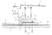
野地板1の勾配下方側に敷設固定される屋根板材2の勾配上部側敷設部3の上面に、野地板1の勾配上方側に敷設固定される屋根板材2の勾配下部側敷設部5の下面を上方から重ねて上下の屋根板材2同士を接合していく横葺屋根Yに、ソーラーパネル7若しくはソーラーパネル7を取付するためのソーラーパネル取付具8を固定するソーラーパネル用固定金具9を設けた横葺屋根Yにおいて、前記屋根板材2は、前記勾配上部側敷設部3に、上方へ立上がる形状に折曲形成された立上がり受部4を有すると共に、前記勾配下部側敷設部5に、この勾配下部側敷設部5の下面を前記勾配上部側敷設部3の上面に上方から重ねた際に前記立上がり受部4に重合可能で且つ下方へ垂下する形状に折曲形成された垂下重合部6を有する構成とし、前記ソーラーパネル用固定金具9は、前記屋根板材2の勾配上部側敷設部3とこの勾配上部側敷設部3に上方から重ねる前記勾配下部側敷設部5との間に挟み込み状態に配設する屋根側取付部10を有すると共に、この屋根側取付部10を勾配上部側敷設部3と勾配下部側敷設部5との間に配設した際に、重合する前記垂下重合部6と前記立上がり受部4よりも野地板1の勾配下方側に向かって突出する形状で且つ前記ソーラーパネル7若しくは前記ソーラーパネル取付具8を固定可能なパネル固定部11を有する構成とし、前記屋根板材2の勾配上部側敷設部3と前記野地板1との間に配設する合成樹脂製の金具支持スペーサ12を備えて、この金具支持スペーサ12が下方に配設された前記屋根板材2の勾配上部側敷設部3上に前記ソーラーパネル用固定金具9の前記屋根側取付部10を載置し、この屋根側取付部10の上方から複数の止着具13を勾配上部側敷設部3及び金具支持スペーサ12を貫通して野地板1に止着することによりこの屋根側取付部10を勾配上部側敷設部3と金具支持スペーサ12と共に野地板1に固定し、この屋根側取付部10の上方から屋根板材2の勾配上部側敷設部3に別の屋根板材2の前記勾配下部側敷設部5を重ねて、この上方に重ねた屋根板材2の前記垂下重合部6を下方の屋根板材2の前記立上がり受部4に重合させ、この重合させた垂下重合部6と立上がり受部4を接合具14により接合して成ることを特徴とする横葺屋根に係るものである。
The upper surface of the slope upper
また、前記金具支持スペーサ12は、前記屋根板材2の前記立上がり受部4の高さ寸法と同等、若しくは立上がり受部4の高さ寸法よりやや小さい板厚寸法を有する板状体に構成して、この金具支持スペーサ12を前記屋根板材2の前記勾配上部側敷設部3の上側端部からこの勾配上部側敷設部3と前記野地板1との間に挿入配設し得るように構成したことを特徴とする請求項1記載の横葺屋根に係るものである。
Further, the
また、前記金具支持スペーサ12は、発砲ポリスチレン製とし、前記止着具13は、ビスを採用したことを特徴とする請求項1,2のいずれか1項に記載の横葺屋根に係るものである。
Further, the
また、前記ソーラーパネル用固定金具9は、前記屋根側取付部10を前記屋根板材2の勾配上部側敷設部3とこの勾配上部側敷設部3に上方から重ねる前記勾配下部側敷設部5との間に挟み込み状態に配設した際に、屋根板材2の前記垂下重合部6を収容可能な収容凹部15を有する構成としたことを特徴とする請求項1〜3のいずれか1項に記載の横葺屋根に係るものである。
Further, the solar
また、前記屋根板材2の勾配上部側敷設部3と前記ソーラーパネル用固定金具9の前記屋根側取付部10との間と、この屋根側取付部10と前記屋根板材2の勾配下部側敷設部5との間に、防水材16を配設したことを特徴とする請求項1〜4のいずれか1項に記載の横葺屋根に係るものである。
Further, between the slope upper
本発明は上述のように構成したから、勾配上部側敷設部に巻き込み部を有しない屋根板材を使用するために、勾配上部側敷設部の下方に金具支持スペーサを配設可能な構成を簡易に設計でき、また、本発明の合成樹脂製の金具支持スペーサは、腐食しづらく高い耐久性を発揮でき、しかも本発明は、ソーラーパネル用固定金具(の屋根側取付部)が、複数の止着具により屋根板材の勾配上部側敷設部と金具支持スペーサと共に野地板に強固に一体化された屋根構造となると共に、高い固定強度を発揮するソーラーパネル用固定金具を設計可能な構成であるために、ソーラーパネル用固定金具(の屋根側取付部)を垂木に止着固定せずとも野地板に止着固定するだけで十分な金具固定強度を確保でき、これにより新築・改築を問わず且つ野地板を有する屋根であれば木造・鉄骨造を問わずに自由度の高いソーラーパネルの設置施工が容易に可能となるなど、極めて実用性に優れた横葺屋根となる。 Since the present invention is configured as described above, in order to use a roof plate material that does not have a winding portion in the gradient upper side laying portion, a configuration in which a metal support spacer can be disposed below the gradient upper side laying portion is simplified. The synthetic resin bracket support spacer of the present invention can be designed to exhibit high durability without being easily corroded, and in addition, the present invention provides a solar panel fixing bracket (of the roof side mounting portion) having a plurality of fastenings. Because it has a roof structure that is firmly integrated with the base plate together with the slope upper side laying part of the roof plate material and the bracket support spacer, and the solar panel fixing bracket that exhibits high fixing strength can be designed Even if the solar panel fixing bracket (the roof side mounting part) is not fixed to the rafter, it can be secured to the base plate, so that sufficient metal fixing strength can be secured. Ground plane And installing construction of a high degree of freedom solar panels regardless of wood-steel frame as long as the roof has become easily, a transverse 葺 roof extremely excellent in practicality.
また、請求項2記載の発明においては、金具支持スペーサを屋根板材の勾配上部側敷設部と野地板との間に容易に配設することができる一層施工性に優れた構成の横葺屋根となる。
Further, in the invention according to
また、請求項3記載の発明においては、前記作用・効果を確実に発揮する金具支持スペーサを簡易に設計実現可能となる上、この金具支持スペーサを貫通した止着具の緩みを生じにくいなど、一層実用性に優れた構成の横葺屋根となる。
In addition, in the invention according to
また、請求項4記載の発明においては、ソーラーパネル用固定金具の屋根側取付部に上方から重ねる屋根板材の垂下重合部を収容凹部に収容できるので、ソーラーパネル用固定金具を配設する位置の垂下重合部を切断除去することなく施工作業を行うことができる一層施工性に優れた構成の横葺屋根となる。 Further, in the invention according to claim 4, since the hanging overlapping portion of the roofing plate material that overlaps the roof-side mounting portion of the solar panel fixing bracket from above can be accommodated in the accommodating recess, the position of the solar panel fixing bracket is arranged. It becomes the recumbent roof of the structure which was able to perform construction work without cutting and removing a drooping superposition | polymerization part, and was further excellent in construction property.
また、請求項5記載の発明においては、ソーラーパネル用固定金具の取付部位の防水性が確保される一層実用性に優れた構成の横葺屋根となる。
Further, in the invention according to
好適と考える本発明の実施形態を、図面に基づいて本発明の作用を示して簡単に説明する。 An embodiment of the present invention which is considered to be suitable will be briefly described with reference to the drawings showing the operation of the present invention.
野地板1の勾配下方側に屋根板材2を敷設固定し、この屋根板材2の勾配上部側敷設部3と野地板1との間に、合成樹脂製の金具支持スペーサ12を配設し、この金具支持スペーサ12が下方に配設された屋根板材2の勾配上部側敷設部3上にソーラーパネル用固定金具9の屋根側取付部10を載置し、この屋根側取付部10の上方から複数の止着具13を勾配上部側敷設部3及び金具支持スペーサ12を貫通して野地板1に止着することにより、この屋根側取付部10を勾配上部側敷設部3,金具支持スペーサ12と共に野地板1に固定する。
The
この際、本発明の屋根板材2は、勾配上部側敷設部3と勾配下部側敷設部5とに巻き込み部を有しない構成であるから、特別な加工を要することなく勾配上部側敷設部3の下方に金具支持スペーサ12を配設可能な既存の屋根板材2を採用可能であり、このような屋根板材2を採用することによって施工性が向上することになる。
At this time, the
次いで、この固定された屋根側取付部10に、上方から別の屋根板材2の前記勾配下部側敷設部5を重ねて、この重ねた屋根板材2の垂下重合部6を先に固定した屋根板材2の立上がり受部4に重合させ、この重合させた垂下重合部6と立上がり受部4を接合具14により接合すると、野地板1の勾配上方側に敷設固定した屋根板材2と勾配下方側に敷設固定した屋根板材2とが接合されると共に、この重合接合した垂下重合部6と立上がり受部4よりも野地板1の勾配下方側に向かってソーラーパネル用固定金具9のパネル固定部11が突出した本発明の横葺屋根Yが完成する。そして、この突出するパネル固定部11に、ソーラーパネル7若しくはソーラーパネル7を取付するためのソーラーパネル取付具8を固定して、屋根上にソーラーパネル7を設置する。
Subsequently, the sloped lower
このように構成した本発明の横葺屋根Yは、ソーラーパネル用固定金具9(の屋根側取付部10)が、複数の止着具13により屋根板材2(の勾配上部側敷設部3)と金具支持スペーサ12と共に野地板1に強固に一体化された構造となるため、ソーラーパネル用固定金具9(の屋根側取付部10)を垂木17に止着固定しなくとも、野地板1に止着固定することだけで十分な金具固定強度を確保できる。
The recumbent roof Y of the present invention configured as described above has the solar panel fixing bracket 9 (the roof side mounting portion 10) and the roof plate material 2 (the gradient upper side laying portion 3) by the plurality of
また、本発明は、ソーラーパネル用固定金具の屋根側取付部を屋根板材の勾配上部側敷設部より上方の野地板に敷設した金具支持スペーサに止着固定する前記特許文献1のような従来構造に比べて、金具支持スペーサ12が野地板1の勾配下方側の屋根板材2の勾配上部側敷設部3と重なって固定される分、ソーラーパネル用固定金具9の屋根側取付部10の野地板1勾配方向に沿った長さが不要となり、従ってこの屋根側取付部10の野地板1勾配方向に沿った長さを短く設計可能である。
Further, the present invention provides a conventional structure such as Patent Document 1 in which the roof-side mounting portion of the solar panel fixing bracket is fixedly secured to a bracket support spacer laid on the base plate above the sloped upper side laying portion of the roof plate material. Compared to the base plate, the base plate of the roof
また、屋根板材2が、勾配上部側敷設部3と勾配下部側敷設部5とを巻き込んで(ハゼ締めして)接合するような構造ではないため、このような構造に比べると、巻き込み部がない分ソーラーパネル用固定金具9の屋根側取付部10の野地板1勾配に沿った長さが不要となり、このことによっても屋根側取付部10の野地板1勾配方向に沿った長さを短く設計可能である。
Moreover, since the roof board |
このように本発明は、ソーラーパネル用固定金具9の屋根側取付部10の、野地板1の勾配方向に沿った長さを短く設計することが容易に可能である。そのため、ソーラーパネル用固定金具9が長く屋根側取付部10の止着固定位置とパネル固定部11とが離れた構造であると、パネル固定部11が荷重を受けた際に屋根側取付部10を野地板1から外そうとする不都合なテコ作用を生じてしまうことが懸念されるが、本発明では、屋根側取付部10の止着固定位置とパネル固定部11とが近接する固定金具構造にでき、これにより上記のような不都合なテコ作用を生じることなく金具固定強度を確保でき、パネル固定部11が受ける荷重を屋根側取付部10を介して強固に一体化された金具支持スペーサ12で直接的に支持できる構成が実現することになる。
As described above, according to the present invention, it is possible to easily design the length of the roof-
従って、本発明によれば、垂木17位置に限らず、野地板1上であればどこにでもソーラーパネル用固定金具9を金具固定強度を確保しつつ固定可能であるので、新築・改築にかかわらず、また野地板1を有する屋根構造であれば、木造・鉄骨造を問わずにソーラーパネル7の設置施工が容易に可能となり、設計の自由度も高い。
Therefore, according to the present invention, it is possible to fix the solar
また、本発明で採用する合成樹脂製の金具支持スペーサ12は、耐候性に優れ腐食しづらいので、高い耐久性を発揮する。
In addition, the
本発明の具体的な実施例について図面に基づいて説明する。 Specific embodiments of the present invention will be described with reference to the drawings.
本実施例は、図1,図7に示すように、野地板1の勾配下方側に敷設固定される屋根板材2の勾配上部側敷設部3の上面に、野地板1の勾配上方側に敷設固定される屋根板材2の勾配下部側敷設部5の下面を上方から重ねて上下の屋根板材2同士を接合していく横葺屋根Yに適用したもので、前記屋根板材2の勾配上部側敷設部3と前記野地板1との間に配設する合成樹脂製の金具支持スペーサ12を備えて、この金具支持スペーサ12を介してソーラーパネル7若しくはソーラーパネル7を取付するためのソーラーパネル取付具8を固定するソーラーパネル用固定金具9を野地板1に取付した構成としている。
In this embodiment, as shown in FIGS. 1 and 7, it is laid on the upper surface of the slope upper
また、本実施例の屋根板材2は、図4に示すように、野地板1の勾配方向と直交する横方向に長さを有する横長の方形板状であって、勾配上部側敷設部3に、上方へ立上がる形状に折曲形成された立上がり受部4を有すると共に、前記勾配下部側敷設部5の下端部に、この勾配下部側敷設部5の下面を前記勾配上部側敷設部3の上面に上方から重ねた際に前記立上がり受部4に重合可能で且つ下方へ垂下する形状に折曲形成された垂下重合部6を有する構成としている。
Further, as shown in FIG. 4, the
具体的には、天然石が吹付けられたガルバリウム鋼板屋根材等に採用される、勾配上部側敷設部3と勾配下部側敷設部5とに巻き込み部を有しない構成の屋根板材2であって、重合させた前記垂下重合部6と前記立上がり受部4を接合具14としてのビス14によりこの前記垂下重合部6と前記立上がり受部4を貫通させて接合すると、野地板1の勾配上方側に敷設固定した屋根板材2と勾配下方側に敷設固定した屋根板材2とが接合される構成の屋根板材2を採用している(図1,図7参照。)。
Specifically, the
本実施例のソーラーパネル用固定金具9は、前記屋根板材2の勾配上部側敷設部3とこの勾配上部側敷設部3に上方から重ねる前記勾配下部側敷設部5との間に挟み込み状態に配設する屋根側取付部10を有すると共に、この屋根側取付部10を勾配上部側敷設部3と勾配下部側敷設部5との間に配設した際に、重合する前記垂下重合部6と前記立上がり受部4よりも野地板1の勾配下方側に向かって突出する形状で且つ前記ソーラーパネル7若しくは前記ソーラーパネル取付具8を固定可能なパネル固定部11を有する構成としている。
The solar
具体的には、ソーラーパネル用固定金具9は、図2に示すように、一枚の帯状の金属板で構成したもので、金属板の一側部を平板状に形成し、この一側平板部に止着具13としてのビス13を挿通可能な止着孔18を複数箇所(図面では六箇所)に整列状態に貫通形成して、この止着孔18を有する金属板の一側平板部を前記屋根側取付部10としている。
Specifically, as shown in FIG. 2, the solar
また、このソーラーパネル用固定金具9を構成する金属板の他側端部を、前記屋根側取付部10に対して直角下方へ折曲して小さく(10〜12mm程度)垂下させた後、この垂下部19の先端部を金属板の他端の外方に向けて直角に折曲して小さく(14〜16mm程度)水平突設させ、更にこの下部水平部20の先端部を直角上方へ折曲して屋根側取付部10より上方位置にまで大きく(36〜39mm程度)立直させた後、この立直部21の先端部を金属板の他端の外方に向けて直角に折曲して大きく(29〜31mm程度)水平突設させた形状に形成し、更にこの上部水平部22に、金属板の長さ方向と直交する方向に40mm程度の孔長を有する長孔状のボルト取付孔23を貫通形成している。
Further, after the other side end of the metal plate constituting the solar
そして、この垂下部19と下部水平部20と立直部21とで構成される金属板上面側の前記屋根側取付部10より一段低い凹所を、前記屋根側取付部10を前記屋根板材2の勾配上部側敷設部3とこの勾配上部側敷設部3に上方から重ねられる前記勾配下部側敷設部5との間に挟み込み状態に配設した際に、屋根板材2の前記垂下重合部6が収容される収容凹部15としている。即ち、ソーラーパネル用固定金具9は、その長さ方向の中間位置に垂下重合部6を迂回する形状の収容凹部15を設けた構成として、このソーラーパネル用固定金具9が配設する位置の垂下重合部6を切断除去することなく、そのまま垂下重合部6が収容凹部15に収容される構成としている。
Then, a recess that is one step lower than the roof-
また、立直部21と上部水平部22とで構成される背高い突出部を前記パネル固定部11として、このパネル固定部11の前記ボルト取付孔23に取り付けた取付ボルト25に、ソーラーパネル7若しくはソーラーパネル7を取付するためのソーラーパネル取付具8を固定する構成としている(図面は、取付ボルト25にソーラーパネル取付具8を固定し、このパネル取付具8にソーラーパネル7を取付した場合を示している。)。
Further, a tall projecting portion composed of the
また、この際、ボルト取付孔23を長孔状としたことにより、取付ボルト25はボルト取付孔23に沿って移動可能であり、これにより様々なメーカーのソーラーパネル7若しくはソーラーパネル取付具8の取付に対応できると共に、施工誤差を吸収したり、ソーラーパネル7若しくはソーラーパネル取付具8の位置調整を行ったりすることが可能で、ソーラーパネル7若しくはソーラーパネル取付具8の設置施工作業を円滑に実施できる構成としている。
At this time, since the
また、垂下部19の下面側を、前記屋根側取付部10を屋根板材2の勾配上部側敷設部3に載置した際に屋根板材2の前記立上がり受部4に重合若しくは近接する受部重合面24としている。
Further, when the roof-
また、本実施例では、前記金具支持スペーサ12を野地板1の勾配下方側の屋根板材2の勾配上部側敷設部3と重ねて固定する構成のため、ソーラーパネル用固定金具の屋根側取付部を屋根板材の勾配上部側敷設部より上方の野地板に敷設した金具支持スペーサに止着固定する前記特許文献1のような従来構造に比べて、ソーラーパネル用固定金具9の屋根側取付部10の野地板1勾配方向に沿った長さを短く形成可能である。
Further, in this embodiment, the
更に、屋根板材2が、勾配上部側敷設部3と勾配下部側敷設部5とを巻き込んで(ハゼ締めして)接合するような構造ではないから、このような構造に比べると、巻き込み部がない分ソーラーパネル用固定金具9の屋根側取付部10の野地板1勾配に沿った長さを短く形成可能である。
Furthermore, since the
そこで、本実施例では、ソーラーパネル用固定金具9の屋根側取付部10とパネル固定部11との距離が、必要最低限となるように金具長を短く設定している。即ち、ソーラーパネル用固定金具9が長く屋根側取付部10の止着固定位置とパネル固定部11とが離れた構造であると、パネル固定部11が荷重を受けた際に屋根側取付部10を野地板1から外そうとする不都合なテコ作用を生じてしまうことが懸念されるが、本実施例では、屋根側取付部10の止着固定位置とパネル固定部11とが近接する固定金具構造のため、上記のような不都合なテコ作用を生じることなく(このテコ作用による野地板1,屋根板材2,ソーラーパネル用固定金具9の変形を抑制でき)、パネル固定部11が受ける荷重を屋根側取付部10を介して強固に一体化された金具支持スペーサ12で直接的に支持できる構成としている。
Therefore, in this embodiment, the metal fitting length is set to be short so that the distance between the roof-
また、ソーラーパネル用固定金具9を、金具長を短くコンパクト化したことにより、変形を生じにくい高強度な金具となると共に、屋根板材2や金具支持スペーサ12と一体化し易く高い固定強度を発揮できる金具となり、その上、取扱い容易で設置施工性に優れると共に、ソーラーパネル用固定金具9が軽量化することにより太陽光発電システム全体の総重量を軽減できて屋根構造体への負担を軽減できることになる。
In addition, the solar
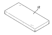
また、本実施例の金具支持スペーサ12は、発砲ポリスチレン製とし、図3,図4,図6に示すように、野地板1の勾配方向と直交する横方向に長さを有する横長方形板状体に構成している。
The
具体的には、金具支持スペーサ12は、前記屋根板材2の前記立上がり受部4の高さ寸法と同等、若しくは立上がり受部4の高さ寸法よりやや小さい板厚寸法を有する板状体に構成して、この金具支持スペーサ12を前記屋根板材2の前記勾配上部側敷設部3の上側端部から、この勾配上部側敷設部3を上方へ撓ませることによって勾配上部側敷設部3と前記野地板1との間に挿入配設し得るように構成している。更に詳しくは、金具支持スペーサ12は、横幅150mm,奥行き幅(野地板1の勾配方向に沿った幅)70mm,板厚12mm程度の方形板状体に形成している。
Specifically, the
このような合成樹脂製(発砲ポリスチレン製)の金具支持スペーサ12は、耐候性に優れ経年劣化しにくく(腐りにくく)、高い耐久性を発揮すると共に、止着具13としてのビス13をネジ込むと、このビス13が良好に噛み込んで緩みを生じにくい。尚、金具支持スペーサ12は、他の合成樹脂製でも良いが、本実施例のように発砲ポリスチレン製とすると、上記効果が良好に発揮されることが出願人の試作実験により確認されている。
The
また、ここで本実施例の止着具13について詳しく説明すると、木ネジタイプのビス13であって、屋根板材2の材質と異種金属による電解腐食を抑止可能な溶融亜鉛メッキビスを採用している。
Further, here, the
次に、本実施例の横葺屋根Yの施工手順を説明する。 Next, the construction procedure of the horizontal roof Y of the present embodiment will be described.
野地板1の勾配下方側に屋根板材2を敷設固定し、この敷設固定した屋根板材2の勾配上部側敷設部3と野地板1との間に、この勾配上部側敷設部3の上方側から金具支持スペーサ12を挿入配設して、金具支持スペーサ12の野地板1勾配下方側の端面を屋根板材2の立上がり受部4の裏面側に当接させた上で、勾配上部側敷設部3の上方から四本の止着具13(ビス13)を勾配上部側敷設部3及び金具支持スペーサ12を貫通して野地板1に止着すすることにより金具支持スペーサ12を勾配上部側敷設部3と共に野地板1に固定する。
A
この際、垂木17をねらって野地板1に止着具13をネジ込みする必要はない。
At this time, it is not necessary to screw the
次いで、下方に金具支持スペーサ12が配設される屋根板材2の勾配上部側敷設部3上に横長方形板状の防水材16を貼り付け、この防水材16上にソーラーパネル用固定金具9の屋根側取付部10を載置すると共に、ソーラーパネル用固定金具9の前記受部重合面24を屋根板材2の立上がり受部3に面接重合若しくは近接させ、この屋根側取付部10の上方から前記止着孔18に向けて止着孔18と同数の止着具13を勾配上部側敷設部3及び金具支持スペーサ12を貫通して野地板1に止着することにより、この屋根側取付部10を勾配上部側敷設部3,金具支持スペーサ12と共に野地板1に固定する。
Next, a
次いで、ソーラーパネル用固定金具9の屋根側取付部10の前記収容凹部15近傍の上面と、これに隣接する勾配上部側敷設部3の上面とに横長棒状の防水材16を貼り付けた上で、別の屋根板材2の勾配下部側敷設部5を屋根側取付部10に上方から重ね、この重ねた屋根板材2の垂下重合部6を下方に固定された屋根板材2の立上がり受部4に重合させると共に、ソーラーパネル用固定金具9の上方に存する垂下重合部6は一段低い前記収容凹部15に収容し、この重合させた垂下重合部6と立上がり受部4を接合具14により接合することにより、野地板1の勾配上方側に敷設固定した屋根板材2と勾配下方側に敷設固定した屋根板材2とが接合されると共に、この重合接合した垂下重合部6と立上がり受部4よりも野地板1の勾配下方側に向かってソーラーパネル用固定金具9のパネル固定部11が突出することになる。この作業を繰り返して(ソーラーパネル用固定金具9が不要な箇所は通常通りの屋根板材2の接合を行って)、所望の位置にソーラーパネル用固定金具9のパネル固定部11が突出する本実施例の横葺屋根Yを完成させる。
Next, a horizontally long stick-shaped
そして、この突出するパネル固定部11に、ソーラーパネル取付具8を固定して、屋根上にソーラーパネル7を設置可能である。
And the solar panel fixture 8 can be fixed to this protruding
図中符号26はアスファルトルーフィングである。
尚、本発明は、本実施例に限られるものではなく、各構成要件の具体的構成は適宜設計し得るものである。 Note that the present invention is not limited to this embodiment, and the specific configuration of each component can be designed as appropriate.
1 野地板
2 屋根板材
3 勾配上部側敷設部
4 立上がり受部
5 勾配下部側敷設部
6 垂下重合部
7 ソーラーパネル
8 ソーラーパネル取付具
9 ソーラーパネル用固定金具
10 屋根側取付部
11 パネル固定部
12 金具支持スペーサ
13 止着具
14 接合具
15 収容凹部
16 防水材
Y 横葺屋根
DESCRIPTION OF SYMBOLS 1
10 Roof side mounting
11 Panel fixing part
12 Bracket support spacer
13 Fastener
14 Joint
15 Housing recess
16 Waterproof material Y Yokohama roof
Claims (5)
Priority Applications (1)
| Application Number | Priority Date | Filing Date | Title |
|---|---|---|---|
| JP2012227326A JP5480353B1 (en) | 2012-10-12 | 2012-10-12 | Bubo roof |
Applications Claiming Priority (1)
| Application Number | Priority Date | Filing Date | Title |
|---|---|---|---|
| JP2012227326A JP5480353B1 (en) | 2012-10-12 | 2012-10-12 | Bubo roof |
Publications (2)
| Publication Number | Publication Date |
|---|---|
| JP5480353B1 true JP5480353B1 (en) | 2014-04-23 |
| JP2014080737A JP2014080737A (en) | 2014-05-08 |
Family
ID=50749943
Family Applications (1)
| Application Number | Title | Priority Date | Filing Date |
|---|---|---|---|
| JP2012227326A Active JP5480353B1 (en) | 2012-10-12 | 2012-10-12 | Bubo roof |
Country Status (1)
| Country | Link |
|---|---|
| JP (1) | JP5480353B1 (en) |
Families Citing this family (4)
| Publication number | Priority date | Publication date | Assignee | Title |
|---|---|---|---|---|
| CN103997284B (en) * | 2014-05-19 | 2016-03-30 | 苏州爱康金属科技有限公司 | Trapezoidal color steel roofing photovoltaic support structure |
| JP6888193B2 (en) * | 2017-01-31 | 2021-06-16 | 株式会社Lixil | Solar panel mounting structure and its construction method |
| JP2020070696A (en) * | 2018-11-02 | 2020-05-07 | 日鉄日新製鋼株式会社 | Roof structure and manufacturing method therefor |
| JP7426155B1 (en) | 2023-02-27 | 2024-02-01 | 有限会社入山屋根工事店 | Exterior component mounting bracket for single roof and exterior component installation method for the same roof |
Family Cites Families (2)
| Publication number | Priority date | Publication date | Assignee | Title |
|---|---|---|---|---|
| JPH0988256A (en) * | 1995-09-25 | 1997-03-31 | Takayama Kinzoku Kogyo Kk | Metal fitting for article installed onto roof |
| JP3322591B2 (en) * | 1997-02-20 | 2002-09-09 | 大同鋼板株式会社 | Mounting brackets for attached structures on horizontal roofs and mounting structures for attached structures on horizontal roofs |
-
2012
- 2012-10-12 JP JP2012227326A patent/JP5480353B1/en active Active
Also Published As
| Publication number | Publication date |
|---|---|
| JP2014080737A (en) | 2014-05-08 |
Similar Documents
| Publication | Publication Date | Title |
|---|---|---|
| JP5116238B2 (en) | Solar panel fixing structure | |
| JP5480353B1 (en) | Bubo roof | |
| JP5396109B2 (en) | Roof tile for roof panel installation and installation method of roof panel | |
| JP5411039B2 (en) | Roof mount installation structure | |
| JP3894931B2 (en) | Solar panel mounting base | |
| JP5945407B2 (en) | Solar cell panel laying structure and solar cell panel intermediate holding member | |
| JP5100464B2 (en) | Structure for fixing parting material to folded-plate roof and folded-plate roof greening structure with the same | |
| JP6045021B2 (en) | Attaching tool for installation on the roof and method of attaching the installation on the roof using the attachment | |
| JP6577169B2 (en) | Mounting structure of solar panel mount and construction method of solar panel mount | |
| JP2012215030A (en) | Mounting structure for on-roof installation | |
| JP5882704B2 (en) | Solar cell panel laying structure and solar cell panel fixing member | |
| JP6062671B2 (en) | Installation structure of roofed structures | |
| JP5714873B2 (en) | Mounting member | |
| JP6192453B2 (en) | Roof structure, solar cell module fixture, solar cell module mounting structure, and solar cell module mounting method | |
| JP6093496B2 (en) | Base support and roof | |
| JP6719225B2 (en) | Strut mounting structure for wooden flat roof | |
| JP5888580B2 (en) | Method of mounting roof layout equipment on roof, roof structure with roof layout equipment, mounting base and waterproof plate for mounting roof layout equipment | |
| JP5675913B1 (en) | Solar panel mounting bracket for metal roof | |
| JP2012047007A (en) | Attachment structure of support frame and exterior structure | |
| JP6968559B2 (en) | Stand for solar cell module and photovoltaic power generation device | |
| JP4084611B2 (en) | Building exterior structure | |
| JP6888192B2 (en) | Solar panel mounting structure | |
| JP4728109B2 (en) | Fixing structure of heat insulating material to standing folding plate roof and heat insulating roof using it | |
| JP6505989B2 (en) | Pedestal with roof | |
| JP5963718B2 (en) | Support member |
Legal Events
| Date | Code | Title | Description |
|---|---|---|---|
| A621 | Written request for application examination |
Free format text: JAPANESE INTERMEDIATE CODE: A621 Effective date: 20121220 |
|
| TRDD | Decision of grant or rejection written | ||
| A01 | Written decision to grant a patent or to grant a registration (utility model) |
Free format text: JAPANESE INTERMEDIATE CODE: A01 Effective date: 20140203 |
|
| A61 | First payment of annual fees (during grant procedure) |
Free format text: JAPANESE INTERMEDIATE CODE: A61 Effective date: 20140213 |
|
| R150 | Certificate of patent or registration of utility model |
Ref document number: 5480353 Country of ref document: JP Free format text: JAPANESE INTERMEDIATE CODE: R150 |
|
| R250 | Receipt of annual fees |
Free format text: JAPANESE INTERMEDIATE CODE: R250 |
|
| R250 | Receipt of annual fees |
Free format text: JAPANESE INTERMEDIATE CODE: R250 |
|
| R250 | Receipt of annual fees |
Free format text: JAPANESE INTERMEDIATE CODE: R250 |
|
| R250 | Receipt of annual fees |
Free format text: JAPANESE INTERMEDIATE CODE: R250 |
|
| S111 | Request for change of ownership or part of ownership |
Free format text: JAPANESE INTERMEDIATE CODE: R313113 |
|
| S631 | Written request for registration of reclamation of domicile |
Free format text: JAPANESE INTERMEDIATE CODE: R313631 |
|
| R371 | Transfer withdrawn |
Free format text: JAPANESE INTERMEDIATE CODE: R371 |
|
| R350 | Written notification of registration of transfer |
Free format text: JAPANESE INTERMEDIATE CODE: R350 |
|
| S111 | Request for change of ownership or part of ownership |
Free format text: JAPANESE INTERMEDIATE CODE: R313113 |
|
| R350 | Written notification of registration of transfer |
Free format text: JAPANESE INTERMEDIATE CODE: R350 |
|
| R250 | Receipt of annual fees |
Free format text: JAPANESE INTERMEDIATE CODE: R250 |
|
| R250 | Receipt of annual fees |
Free format text: JAPANESE INTERMEDIATE CODE: R250 |
|
| R250 | Receipt of annual fees |
Free format text: JAPANESE INTERMEDIATE CODE: R250 |
|
| R250 | Receipt of annual fees |
Free format text: JAPANESE INTERMEDIATE CODE: R250 |