JP5477981B2 - Liquid ejection apparatus and maintenance method - Google Patents
Liquid ejection apparatus and maintenance method Download PDFInfo
- Publication number
- JP5477981B2 JP5477981B2 JP2012065972A JP2012065972A JP5477981B2 JP 5477981 B2 JP5477981 B2 JP 5477981B2 JP 2012065972 A JP2012065972 A JP 2012065972A JP 2012065972 A JP2012065972 A JP 2012065972A JP 5477981 B2 JP5477981 B2 JP 5477981B2
- Authority
- JP
- Japan
- Prior art keywords
- liquid
- heads
- head
- unit
- supply
- Prior art date
- Legal status (The legal status is an assumption and is not a legal conclusion. Google has not performed a legal analysis and makes no representation as to the accuracy of the status listed.)
- Expired - Fee Related
Links
- 239000007788 liquid Substances 0.000 title claims description 276
- 238000000034 method Methods 0.000 title claims description 60
- 238000012423 maintenance Methods 0.000 title claims description 34
- 238000004140 cleaning Methods 0.000 claims description 91
- 230000008569 process Effects 0.000 claims description 41
- XLYOFNOQVPJJNP-UHFFFAOYSA-N water Substances O XLYOFNOQVPJJNP-UHFFFAOYSA-N 0.000 claims description 40
- 238000011109 contamination Methods 0.000 claims description 11
- 239000005871 repellent Substances 0.000 claims description 11
- 230000002940 repellent Effects 0.000 claims description 10
- 238000001035 drying Methods 0.000 claims description 7
- 238000001514 detection method Methods 0.000 claims description 6
- 238000005304 joining Methods 0.000 claims description 2
- 239000000976 ink Substances 0.000 description 52
- 238000012545 processing Methods 0.000 description 36
- 238000010586 diagram Methods 0.000 description 19
- 230000006870 function Effects 0.000 description 10
- 238000004891 communication Methods 0.000 description 9
- 239000003595 mist Substances 0.000 description 7
- 230000032258 transport Effects 0.000 description 6
- 230000002093 peripheral effect Effects 0.000 description 5
- 238000003860 storage Methods 0.000 description 5
- 239000000853 adhesive Substances 0.000 description 4
- 230000001070 adhesive effect Effects 0.000 description 4
- 238000004519 manufacturing process Methods 0.000 description 4
- 238000010926 purge Methods 0.000 description 4
- 238000010521 absorption reaction Methods 0.000 description 3
- 230000006866 deterioration Effects 0.000 description 3
- 239000011159 matrix material Substances 0.000 description 3
- 230000007246 mechanism Effects 0.000 description 3
- 238000011144 upstream manufacturing Methods 0.000 description 3
- 230000008901 benefit Effects 0.000 description 2
- 230000006835 compression Effects 0.000 description 2
- 238000007906 compression Methods 0.000 description 2
- 239000000463 material Substances 0.000 description 2
- 238000012546 transfer Methods 0.000 description 2
- 238000009736 wetting Methods 0.000 description 2
- 230000015572 biosynthetic process Effects 0.000 description 1
- 238000009835 boiling Methods 0.000 description 1
- 238000001816 cooling Methods 0.000 description 1
- 238000012937 correction Methods 0.000 description 1
- 238000007791 dehumidification Methods 0.000 description 1
- 230000002542 deteriorative effect Effects 0.000 description 1
- 238000011161 development Methods 0.000 description 1
- 238000007865 diluting Methods 0.000 description 1
- 238000007599 discharging Methods 0.000 description 1
- 230000000694 effects Effects 0.000 description 1
- 238000010438 heat treatment Methods 0.000 description 1
- 230000006872 improvement Effects 0.000 description 1
- 238000007689 inspection Methods 0.000 description 1
- 239000002923 metal particle Substances 0.000 description 1
- 239000002245 particle Substances 0.000 description 1
- 238000001454 recorded image Methods 0.000 description 1
- 239000011347 resin Substances 0.000 description 1
- 229920005989 resin Polymers 0.000 description 1
- 239000004065 semiconductor Substances 0.000 description 1
- 238000001179 sorption measurement Methods 0.000 description 1
- 230000003068 static effect Effects 0.000 description 1
- 238000012360 testing method Methods 0.000 description 1
- 238000005406 washing Methods 0.000 description 1
- 239000002699 waste material Substances 0.000 description 1
Images


Classifications
-
- B—PERFORMING OPERATIONS; TRANSPORTING
- B41—PRINTING; LINING MACHINES; TYPEWRITERS; STAMPS
- B41J—TYPEWRITERS; SELECTIVE PRINTING MECHANISMS, i.e. MECHANISMS PRINTING OTHERWISE THAN FROM A FORME; CORRECTION OF TYPOGRAPHICAL ERRORS
- B41J2/00—Typewriters or selective printing mechanisms characterised by the printing or marking process for which they are designed
- B41J2/005—Typewriters or selective printing mechanisms characterised by the printing or marking process for which they are designed characterised by bringing liquid or particles selectively into contact with a printing material
- B41J2/01—Ink jet
- B41J2/135—Nozzles
- B41J2/165—Prevention or detection of nozzle clogging, e.g. cleaning, capping or moistening for nozzles
- B41J2/16517—Cleaning of print head nozzles
- B41J2/16552—Cleaning of print head nozzles using cleaning fluids
-
- B—PERFORMING OPERATIONS; TRANSPORTING
- B41—PRINTING; LINING MACHINES; TYPEWRITERS; STAMPS
- B41J—TYPEWRITERS; SELECTIVE PRINTING MECHANISMS, i.e. MECHANISMS PRINTING OTHERWISE THAN FROM A FORME; CORRECTION OF TYPOGRAPHICAL ERRORS
- B41J2/00—Typewriters or selective printing mechanisms characterised by the printing or marking process for which they are designed
- B41J2/005—Typewriters or selective printing mechanisms characterised by the printing or marking process for which they are designed characterised by bringing liquid or particles selectively into contact with a printing material
- B41J2/01—Ink jet
- B41J2/135—Nozzles
- B41J2/165—Prevention or detection of nozzle clogging, e.g. cleaning, capping or moistening for nozzles
- B41J2/16517—Cleaning of print head nozzles
-
- B—PERFORMING OPERATIONS; TRANSPORTING
- B41—PRINTING; LINING MACHINES; TYPEWRITERS; STAMPS
- B41J—TYPEWRITERS; SELECTIVE PRINTING MECHANISMS, i.e. MECHANISMS PRINTING OTHERWISE THAN FROM A FORME; CORRECTION OF TYPOGRAPHICAL ERRORS
- B41J2/00—Typewriters or selective printing mechanisms characterised by the printing or marking process for which they are designed
- B41J2/005—Typewriters or selective printing mechanisms characterised by the printing or marking process for which they are designed characterised by bringing liquid or particles selectively into contact with a printing material
- B41J2/01—Ink jet
- B41J2/135—Nozzles
- B41J2/165—Prevention or detection of nozzle clogging, e.g. cleaning, capping or moistening for nozzles
- B41J2/16585—Prevention or detection of nozzle clogging, e.g. cleaning, capping or moistening for nozzles for paper-width or non-reciprocating print heads
Landscapes
- Ink Jet (AREA)
Description
本発明は液体吐出装置及びメンテナンス方法に係り、特に複数のヘッドユニットをつなぎ合わせて構成されたライン型インクジェットヘッドのメンテナンス技術に関する。 The present invention relates to a liquid ejection apparatus and a maintenance method, and more particularly to a maintenance technique for a line-type inkjet head configured by connecting a plurality of head units.
記録媒体にカラー画像を形成するインクジェット記録装置には、記録媒体の全幅に対応する長さにわたってノズルが設けられるライン型のインクジェットヘッド(ラインヘッド)を備える構成がある。 2. Description of the Related Art An inkjet recording apparatus that forms a color image on a recording medium has a configuration including a line-type inkjet head (line head) in which nozzles are provided over a length corresponding to the entire width of the recording medium.
ラインヘッドには、複数のヘッド(ヘッドモジュール、ヘッドユニット)をつなぎ合わせた形態がある。このようなラインヘッドは、製造上の精度の向上や製造歩留まりの向上が見込まれるとともに、製造時の検査において不合格となった場合や、故障の発生や寿命により交換を要する場合には、ヘッドごとに交換することができるというメリットもある。 The line head has a form in which a plurality of heads (head module, head unit) are connected. Such a line head is expected to improve manufacturing accuracy and manufacturing yield, and if it is rejected in the inspection during manufacturing, or if it needs to be replaced due to the occurrence of a failure or its life, There is also an advantage that it can be exchanged every time.
複数のヘッドをつなぎ合わせて構成されるラインヘッドは、ヘッドをつなぎ合わせるつなぎ部には、ヘッドごとの製造上の誤差や組み立て時の位置決め誤差を吸収するために隙間が設けられている。 In a line head configured by connecting a plurality of heads, a gap is provided in a connecting portion for connecting the heads in order to absorb manufacturing errors for each head and positioning errors during assembly.
このヘッド間の隙間には、インク吐出の際に発生したミストや、ノズル面のワイピングに使用される洗浄液などの液体が溜まりやすく、この液体が記録媒体に落下すると問題となる。 In the gap between the heads, liquid such as mist generated during ink discharge or cleaning liquid used for wiping the nozzle surface is likely to be accumulated, and there is a problem if this liquid falls on the recording medium.
また、隙間に溜まった液体は、液体吐出面(ノズル面)のワイピング時に液体吐出面に流出して、液体吐出面を汚すことや、ヘッドの側面に現れている接着剤を劣化させることが懸念される。 In addition, the liquid accumulated in the gap may flow out to the liquid ejection surface when wiping the liquid ejection surface (nozzle surface), contaminating the liquid ejection surface, or deteriorating the adhesive appearing on the side surface of the head. Is done.
特許文献1は、ノズル面に付着したインクミストが、親水化処理が施されたインクジェット記録ヘッド16A間の隙間に吸い込まれ、隙間を上方に移動して、上部のインク吸収部材に吸収されるように構成されたインクジェット記録装置を開示している。
In
特許文献2は、ノズルプレートに付着したインク等の異物を除去するワイパー部材を清掃する際に、負圧を発生させた吸引口にワイパー部材を移動させて、吸引により異物を除去する構成が開示されている。
しかしながら、特許文献1に開示された構成のように、ヘッドの側面が親液性の場合は、ヘッドの側面(ヘッド間の隙間)にインクが溜まりやすく、吸収部材による吸収ではインクを除去することが困難である。
However, when the side surface of the head is lyophilic as in the configuration disclosed in
一方、ヘッドの側面が撥液性の場合を考えると、インクのような表面張力が小さい液体の接触角は撥液性を有する面であっても90°以下になり、インクが濡れ広がってしまう。濡れ広がったインクは吸収部材による吸収で完全に除去することは困難である。 On the other hand, considering the case where the side surface of the head is liquid repellent, the contact angle of a liquid having a small surface tension such as ink is 90 ° or less even if the surface has liquid repellency, and the ink spreads wet. . It is difficult to completely remove the ink that has spread out by absorption by the absorbing member.
ヘッドの側面に残留したインクは、隙間から落下して記録媒体を汚してしまうおそれがあり、仮に隙間から落下しない場合でも、ヘッドの側面に露出している接着剤などの劣化を誘発して、ヘッドの故障発生の原因となりうる。 The ink remaining on the side of the head may fall from the gap and contaminate the recording medium.Even if it does not fall from the gap, it induces deterioration of the adhesive exposed on the side of the head, This may cause a head failure.
本発明はこのような事情に鑑みてなされたもので、ヘッド間の隙間に入り込んだ液等を効率よく除去することができる、液体吐出装置及びメンテナンス方法を提供することを目的とする。 The present invention has been made in view of such circumstances, and an object thereof is to provide a liquid ejection apparatus and a maintenance method that can efficiently remove liquid and the like that have entered a gap between heads.
上記目的を達成するために、本発明に係る液体吐出装置は、複数のヘッドを長手方向につなぎ合わせて構成され、隣接するヘッドと対向する面となる各ヘッドの側面に撥液処理が施されたラインヘッドと、前記ヘッドの液体吐出面の反対側において、隣接するヘッド間に設けられ、前記ヘッド間へ一方の端が挿入されるチューブを支持するチューブ支持部材と、前記チューブの他方の端に接続され、前記ヘッド間へ前記一方の端から気体を供給する気体供給手段と、を備えている。 In order to achieve the above object, a liquid ejection apparatus according to the present invention is configured by joining a plurality of heads in the longitudinal direction, and a liquid repellent treatment is performed on the side surface of each head that faces a neighboring head. A line support head, a tube support member provided between adjacent heads on the opposite side of the liquid ejection surface of the head, and supporting a tube into which one end is inserted between the heads, and the other end of the tube And gas supply means for supplying gas from the one end to between the heads.
本発明によれば、複数のヘッドをつなぎ合わせた構造を有するラインヘッドを具備する液体吐出装置において、隣接するヘッド間へ気体を供給して、ヘッド間へ入った液体を吹き飛ばすので、ヘッド間の液体を効率よく除去することができる。 According to the present invention, in the liquid ejection apparatus having a line head having a structure in which a plurality of heads are connected together, gas is supplied between adjacent heads, and the liquid that has entered between the heads is blown away. The liquid can be removed efficiently.
以下、添付図面に従って本発明を実施するための形態について詳説する。 Hereinafter, embodiments for carrying out the present invention will be described in detail with reference to the accompanying drawings.
〔第1実施形態〕
<装置全体構成>
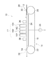
図1は、本発明に係るインクジェット記録装置の全体構成図である。図1に示すインクジェット記録装置10(液体吐出装置)は、オンデマンド型インクジェット記録装置であり、記録媒体12を保持して搬送する記録媒体搬送部14と、記録媒体搬送部14に保持された記録媒体12に対して、K(黒)、C(シアン)、M(マゼンタ)、Y(イエロー)に対応するカラーインクを吐出させるラインヘッド16K,16C,16M,16Yを含む印字部17と、を含んで構成されている。
[First Embodiment]
<Overall configuration of device>
FIG. 1 is an overall configuration diagram of an ink jet recording apparatus according to the present invention. An ink jet recording apparatus 10 (liquid ejection apparatus) shown in FIG. 1 is an on-demand ink jet recording apparatus, and a recording
また、図1では、図示を省略するが、インクジェット記録装置10は、ラインヘッド16K,16C,16M,16Yにメンテナンス処理を施すメンテナンス処理部を備えている(図3参照)。
Although not shown in FIG. 1, the
記録媒体搬送部14は、記録媒体12が保持される記録媒体保持領域に多数の吸着穴(不図示)が設けられた無端状の搬送ベルト18と、搬送ベルト18が巻き掛けられる搬送ローラ(駆動ローラ20、従動ローラ22)と、記録媒体保持領域の搬送ベルト18の裏側(記録媒体12が保持される記録媒体保持面と反対側の面)に設けられ、記録媒体保持領域に設けられた不図示の吸着穴にと連通しているチャンバー24と、チャンバー24に負圧を発生させる真空ポンプ26と、を含んでいる。
The recording
記録媒体12が搬入される搬入部28には、記録媒体12の浮きを防止するための押圧ローラ30が設けられるとともに、記録媒体12が排出される排出部32にもまた、押圧ローラ34が設けられている。
The carry-in
搬入部28から搬入された記録媒体12は、記録媒体保持領域に設けられた吸着穴から負圧が付与され、搬送ベルト18の記録媒体保持領域に吸着保持される。
The
記録媒体12の搬送路上には、印字部17の前段側(記録媒体搬送方向上流側)に、記録媒体12の表面温度を所定範囲に調整するための温度調節部36が設けられるとともに、印字部17の後段側(記録媒体搬送方向下流側)に、記録媒体12上に記録された画像を読み取る読取装置(読取センサ)38が設けられている。
On the conveyance path of the
搬入部28から搬入された記録媒体12は、搬送ベルト18の記録媒体保持領域に吸着保持され、温度調節部36による温度調節処理が施された後に、印字部17において画像記録が行われる。
The
図1に示すように、ラインヘッド16K,16C,16M,16Yは、記録媒体搬送方向の上流側からこの順番で配置されている。記録媒体12がラインヘッド16K,16C,16M,16Yの直下を通過する際に、記録媒体12に対してKCMYの各色のインクを吐出させて、所望のカラー画像が形成される。
As shown in FIG. 1, the
なお、印字部17は上述した形態に限定されない。例えば、LC(ライトシアン)やLM(ライトマゼンタ)に対応するラインヘッド16LC,16LMを具備してもよい。また、ラインヘッド16K,16C,16M,16Yの配置順も適宜変更可能である。
The printing unit 17 is not limited to the above-described form. For example, line heads 16LC and 16LM corresponding to LC (light cyan) and LM (light magenta) may be provided. Further, the arrangement order of the
画像記録がされた記録媒体12は、読取装置38によって記録画像(テストパターン)が読み取られた後に、排出部32から排出される。
The
<印字部の構成>
図2は、印字部17の構成例を示す平面図であり、記録媒体12の描画面側からラインヘッド16(16K,16C,16M,16Y)の液体吐出面を見た図である。以下の説明では、色ごとのラインヘッド16K,16C,16M,16Yを区別する必要がない場合は、ラインヘッド16と記載することがある。
<Configuration of the printing unit>
FIG. 2 is a plan view illustrating a configuration example of the printing unit 17 and is a view of the liquid ejection surface of the line head 16 (16K, 16C, 16M, 16Y) viewed from the drawing surface side of the
同図に示すように、ラインヘッド16は、記録媒体12の全幅に対応する長さにわたって複数のノズル(不図示)を有するフルライン型ヘッドであり、記録媒体12とラインヘッド16とを相対的に一回だけ走査させることで、記録媒体12の全域にわたって画像を形成することができる。
As shown in the figure, the
ここで、記録媒体12の「全幅」とは、記録媒体12の搬送方向(符号Sを付して図示した副走査方向)と直交する方向(符号Mを付して図示した主走査方向)における記録媒体12の全長であり、余白を考慮した場合には画像が形成される画像形成領域の同方向における全長としてもよい。
Here, the “full width” of the
図2に示すように、ラインヘッド16は、複数のインクジェットヘッド16Aを長手方向(主走査方向M)沿ってつなぎ合わせた構造を有している。各ヘッド16A間には、組み立てにおけるクリアランスを調整するために、数100マイクロメートル程度の隙間80が設けられている。
As shown in FIG. 2, the
この隙間80において、隣接するヘッドと対向する面となる各ヘッドの側面(図20に符号16Bを付して図示)は、撥液処理が施された撥液面となっている。
In the
各ヘッド16Aの詳細な構造の図示は省略するが、各ヘッドは、液体を吐出させるノズルと、該ノズルと連通する液室とを備え、さらに、吐出力を発生させる吐出力発生素子を備えている。吐出力発生素子として、液室を構成する壁に圧電素子を備え、圧電素子のたわみ変形により液室を変形させて液体を吐出させる圧電方式を適用することができる。
Although the detailed structure of each
また、吐出力発生素子として、液室内にヒータを備え、該ヒータにより液室内の液体を加熱し、膜沸騰現象を利用して液体を吐出させるサーマル方式を適用することができる。 Further, as the discharge force generating element, a thermal method in which a heater is provided in the liquid chamber, the liquid in the liquid chamber is heated by the heater, and the liquid is discharged using a film boiling phenomenon can be applied.
各ヘッドのノズル配列には、主走査方向と直交しない斜め方向に沿って複数のノズルが並べられ、該斜め方向のノズル列が主走査方向に沿って並べられたマトリクス配列を適用することができる。 As the nozzle arrangement of each head, a matrix arrangement in which a plurality of nozzles are arranged along an oblique direction that is not orthogonal to the main scanning direction, and nozzle rows in the oblique direction are arranged along the main scanning direction can be applied. .
かかるマトリクス配列を適用することで、主走査方向における実質的なノズル密度を高密度することができる。なお、ノズル配列はマトリクス配列に限定されず、主走査方向に沿ってノズルが一列に配列された態様、二列の千鳥配列など、他の配列を適用してもよい。 By applying such a matrix arrangement, the substantial nozzle density in the main scanning direction can be increased. The nozzle arrangement is not limited to the matrix arrangement, and other arrangements such as an aspect in which the nozzles are arranged in a line along the main scanning direction or a two-row staggered arrangement may be applied.
<ラインヘッドのメンテナンス処理の説明>
図3は、ラインヘッド16に対してメンテナンス処理を施すメンテナンス処理部の概略構成図である。
<Description of line head maintenance processing>
FIG. 3 is a schematic configuration diagram of a maintenance processing unit that performs maintenance processing on the
図3に示すメンテナンス処理部60は、ラインヘッド16(16K,16C,16M,16Y)を記録媒体搬送部14上の画像形成位置から、記録媒体12の搬送方向と略直交する方向に水平移動させた位置に配置されている。
The
メンテナンス処理部60は、ラインヘッド16の液体吐出面に洗浄液を付与する洗浄装置62と、ラインヘッド16に対してパージ処理又は吸引処理(ノズル内のインクの排出処理)を施すキャップ部64と、パージ処理又は吸引処理後のラインヘッド16の液体吐出面16Dに対して払拭処理を施すウエブ66を具備する払拭処理部68(払拭手段)と、を備えて構成されている。
The
なお、洗浄装置62と払拭処理部68とを一体に構成してもよいし、洗浄装置62、払拭処理部68、及びキャップ部64を一体に構成してもよい。また、ウエブ66に代わり、又はこれと併用して、ブレード(ワイパー)を備える態様もありうる。
The
図3には、1ラインヘッド分に対応するメンテナンス処理部60の構成が図示されているが、洗浄装置62、キャップ部64、払拭処理部68はラインヘッド16ごとに、ラインヘッド16の数だけ設けられている。なお、複数の洗浄装置62等を一体に構成することも可能である。
FIG. 3 shows the configuration of the
ラインヘッド16を記録媒体搬送部14の直上の画像形成位置(画像形成位置に位置するラインヘッド16を破線により図示)からメンテナンス位置へ移動させるには、ラインヘッド16を記録媒体搬送部14上の画像形成位置から一旦上方へ退避させ、さらに、記録媒体12の搬送方向と直交する方向へ水平移動させる。
In order to move the
ラインヘッド16を上下方向及び水平方向へ移動させる移動機構には、周知の水平搬送機構、上下搬送機構を適用することができる。
As the moving mechanism for moving the
「メンテナンス位置」とは、払拭処理部68の処理領域、洗浄装置62の処理領域、及びキャップ部64の処理領域を含む概念である。なお、図3では、キャップ部64の処理領域に位置するラインヘッド16が一点破線によって図示されている。
The “maintenance position” is a concept including a processing region of the wiping
ラインヘッド16が洗浄装置62の処理領域に到達すると、洗浄装置62を上方へ移動させて(又は、ラインヘッド16を下方へ移動させて)、液体吐出面16Dの洗浄処理が実行される。
When the
液体吐出面16Dの洗浄処理が終了すると、ラインヘッド16をキャップ部64の処理領域へ移動させ、液体吐出面16Dにキャップ部64を密着させて、吸引処理又はパージ処理が実行される。
When the cleaning process of the
キャップ部64は、排出流路72を介して廃インクタンク74と連通され、排出流路72には、ポンプ76が設けられる。液体吐出面16Dにキャップ部64を密着させた状態でポンプ76を動作させると、ノズルを介してラインヘッド16内のインクが吸引される。
The
このようにして、ラインヘッド16のパージ又は吸引処理が終了すると、ラインヘッド16は画像形成位置に移動する。
In this way, when the purge or suction process of the
詳細は後述するが、ラインヘッド16のメンテナンス処理は、ヘッド16A間の隙間80の洗浄処理中、又は洗浄処理後にも実行される。
As will be described in detail later, the maintenance process for the
<ヘッド間洗浄の説明>
図4(a)は、ヘッド間洗浄の構成例を示す説明図であり、ラインヘッド16の液体吐出面(図4中不図示、図3参照)と反対側(同図中、上側)における、隣接するヘッド16A‐1,16A‐2の間の構造が図示されている。また、図4(b)は、図4(a)のA‐A線に沿う断面図である。
<Description of cleaning between heads>
FIG. 4A is an explanatory diagram showing a configuration example of cleaning between heads, on the side opposite to the liquid ejection surface (not shown in FIG. 4, refer to FIG. 3) of the line head 16 (upper side in FIG. 4). A structure between
同図に示すように、隣接するヘッド16A‐1とヘッド16A‐2との間の隙間80には、チューブ支持部材82が挟み込まれており、チューブ支持部材82は該隙間80へエア(供給方向を矢印線により図示)を供給して、インク(ミスト)等を除去するためのエア供給チューブ84(気体供給チューブ)が支持されている。
As shown in the figure, a
チューブ支持部材82は、各ヘッド16A‐1,16A‐2の液体吐出面の反対側から隙間80を覆い、その一部が隙間80の内部に入り込む形状を有している。チューブ支持部材82は、柔軟性を持つゴム部材が適用される。
The
エア供給チューブ84は、フッ素樹脂等の柔軟性を有する材料が適用され、その直径は隙間80の間隔の1/2程度とされる。
The
エア供給チューブ84はチューブ支持部材82を貫通して、一方の端が隙間80に達しており、他方の端部はエア供給部(同図中不図示、図6に符号128を付して図示)と接続されている。
The
図5は、ヘッド間洗浄の他の構成例を示す説明図である。図5に示す態様では、複数のエア供給チューブ84‐1,84‐2,84‐3が設けられている。図5に示す態様では、隙間80の全域に対して確実にエアを供給することができる。
FIG. 5 is an explanatory diagram showing another configuration example of the head cleaning . In the embodiment shown in FIG. 5, a plurality of air supply tubes 84-1, 84-2 and 84-3 are provided. In the embodiment shown in FIG. 5, air can be reliably supplied to the
ヘッド間洗浄は、ラインヘッド16をメンテナンス処理部60の処理領域へ移動させて実行される。ヘッド間洗浄は、ウエブ66によるワイピング処理中に実行されてもよいし、ラインヘッド16をキャップ部64の位置に移動させて、ラインヘッド16がキャッピングされた状態で実行されてもよい。
The head-to-head cleaning is executed by moving the
<制御系の説明>
図6は、図1に示すインクジェット記録装置の制御系の構成を示すブロック図である。同図に示すように、インクジェット記録装置10は、通信インターフェース100、システム制御部102、搬送制御部104、画像処理部106、ヘッド駆動部108を備えるとともに、画像メモリ110、ROM112を備えている。
<Description of control system>
FIG. 6 is a block diagram showing the configuration of the control system of the ink jet recording apparatus shown in FIG. As shown in the figure, the
通信インターフェース100は、ホストコンピュータ114から送られてくるラスター画像データを受信するインターフェース部である。通信インターフェース100は、USB(Universal Serial Bus)などのシリアルインターフェースを適用してもよいし、セントロニクスなどのパラレルインターフェースを適用してもよい。通信インターフェース100は、通信を高速化するためのバッファメモリ(不図示)を搭載してもよい。
The
システム制御部102は、中央演算処理装置(CPU)及びその周辺回路等から構成され、所定のプログラムに従ってインクジェット記録装置10の全体を制御する制御装置として機能するとともに、各種演算を行う演算装置として機能し、さらに、画像メモリ110及びROM112のメモリコントローラとして機能する。
The
すなわち、システム制御部102は、通信インターフェース100、搬送制御部104等の各部を制御し、ホストコンピュータ114との間の通信制御、画像メモリ110及びROM112の読み書き制御等を行うとともに、上記の各部を制御する制御信号を生成する。
That is, the
ホストコンピュータ114から送出された画像データは通信インターフェース100を介してインクジェット記録装置10に取り込まれ、画像処理部106によって所定の画像処理が施される。
Image data sent from the
画像処理部106は、画像データから印字制御用の信号を生成するための各種加工、補正などの処理を行う信号(画像)処理機能を有し、生成した印字データ(ドットデータ)をヘッド駆動部108に供給する制御部である。
The
画像処理部106において所要の信号処理が施されると、該印字データ(ハーフトーン画像データ)に基づいて、ヘッド駆動部108を介してラインヘッド16の吐出液滴量(打滴量)や吐出タイミングの制御が行われる。
When necessary signal processing is performed in the
これにより、所望のドットサイズやドット配置が実現される。なお、図6に示すヘッド駆動部108には、ラインヘッド16の駆動条件を一定に保つためのフィードバック制御系を含んでいてもよい。
Thereby, a desired dot size and dot arrangement are realized. The
搬送制御部104は、画像処理部106により生成された印字データに基づいて記録媒体12(図1参照)の搬送タイミング及び搬送速度を制御する。図6における搬送駆動部116は、記録媒体12を搬送する記録媒体搬送部14の駆動ローラ20(22)を駆動するモータが含まれており、搬送制御部104は該モータのドライバーとして機能している。
The
画像メモリ(一時記憶メモリ)110は、通信インターフェース100を介して入力された画像データを一旦格納する一時記憶手段としての機能や、ROM112に記憶されている各種プログラムの展開領域及びCPUの演算作業領域(例えば、画像処理部106の作業領域)としての機能を有している。画像メモリ110には、逐次読み書きが可能な揮発性メモリ(RAM)が用いられる。
An image memory (temporary storage memory) 110 functions as temporary storage means for temporarily storing image data input via the
ROM112は、システム制御部102のCPUが実行するプログラムや、装置各部の制御に必要な各種データ、制御パラメータなどが格納されており、システム制御部102を通じてデータの読み書きが行われる。ROM112は、半導体素子からなるメモリに限らず、ハードディスクなど磁気媒体を用いてもよい。また、外部インターフェースを備え、着脱可能な記憶媒体を用いてもよい。
The
パラメータ記憶部118は、インクジェット記録装置10の動作に必要な各種制御パラメータが記憶されている。システム制御部102は、制御に必要なパラメータを適宜読み出すとともに、必要に応じて各種パラメータの更新(書換)を実行する。
The
プログラム格納部120は、インクジェット記録装置10を動作させるための制御プログラムが格納されている記憶手段である。システム制御部102(又は装置各部)は、装置各部の制御を実行する際にプログラム格納部120から必要な制御プログラムを読み出し、該制御プログラムは適宜実行される。
The
表示部122は、システム制御部102から送出される各種情報を表示する手段であり、LCDモニタなどの汎用ディスプレイ装置が適用される。なお、表示部122の表示形態には、ランプの点灯(点滅、消灯)を適用してもよい。また、スピーカーなどの音(音声)出力手段を備えてもよい。
The
入力インターフェース(I/F)124は、キーボード、マウス、ジョイスティックなどの情報入力手段が適用される。入力インターフェース124を介して入力された情報は、システム制御部102へ送出される。
As the input interface (I / F) 124, information input means such as a keyboard, a mouse, and a joystick is applied. Information input via the
エア制御部126(気体供給手段の構成要素)は、システム制御部102から送出される制御信号に基づいて、エア供給部128(気体供給手段の構成要素)を制御する。エア供給部128は、エアタンクと、エアを圧縮する圧縮部(コンプレッサー)と、エアの流路となる配管と、エア供給チューブ84との接続部となるジョイントと、が具備される。
The air control unit 126 (component of the gas supply unit) controls the air supply unit 128 (component of the gas supply unit) based on a control signal sent from the
エア供給部128から送り出されたエアは、エア供給チューブ84を介してラインヘッド16のヘッド16A間の隙間(図4参照)に供給され、液体吐出面側から隙間80の内部へ浸入したインクや液体吐出面の洗浄に使用された洗浄液が、隙間80の外部へ吹き飛ばされる。
The air sent out from the
エア供給は、圧力又は流量で制御される。例えば、圧力による制御では、エア供給チューブ84の破損や、ジョイントからのエア漏れなどの破損を防止する観点から圧力は100キロパスカル以下とされる。
Air supply is controlled by pressure or flow rate. For example, in the control by pressure, the pressure is set to 100 kilopascals or less from the viewpoint of preventing breakage of the
圧力の好ましい範囲は、10キロパスカル以上30キロパスカル以下であり、エア供給チューブ84の長さや太さに応じて適宜調整される。また、流量による制御では、流量が数100ミリリットル毎分から1リットル毎分の範囲に制御される。
A preferable range of the pressure is 10 kilopascals or more and 30 kilopascals or less, and is appropriately adjusted according to the length and thickness of the
エア供給部128からドライエア(乾燥気体)を送ることで、ヘッド16A間の隙間80を乾燥させることができる。このように、ヘッド16A間の隙間80を乾燥させることで、接着剤などの劣化が抑制される。
By sending dry air (dry gas) from the
ここで、「ドライエア」とは、相対湿度が20パーセント以下の空気であり、相対湿度を10パーセント以下とするとより好ましい。 Here, “dry air” is air having a relative humidity of 20% or less, and more preferably 10% or less.
ドライエアを生成する例として、エア供給部128から送られたエアに除湿処理を施す除湿部(乾燥手段)を備える態様が挙げられる。除湿部は、圧縮方式、冷却方式、吸着方式、吸収方式などのいずれの方式を適用してもよい。
As an example of generating dry air, an aspect including a dehumidifying unit (drying unit) that performs dehumidification processing on the air sent from the
除湿部は、エア供給部128と一体に構成されてもよいし、エア供給部128とは別に、エア供給部128とヘッド16A間の隙間80との間に設けられていてもよい。
The dehumidifying unit may be configured integrally with the
メンテナンス制御部130は、システム制御部102から送出される指令信号に応じて、図3に図示したメンテナンス処理部60の動作を制御する。すなわち、メンテナンス制御部130は、図3に図示した洗浄装置62のキャップ部64の昇降、ポンプ76のオンオフ、回転数、ウエブ66の昇降などを制御する。
The
上記の如く構成されたインクジェット記録装置10によれば、ラインヘッド16のヘッド16A間の隙間80にエアを供給して、該隙間80に溜まったインク、ミスト等を吹き飛ばすので、吸引を用いて該インク等を除去することが困難な場合でも、該隙間80に溜まった液体効率よく除去することが可能となる。
According to the
〔第2実施形態〕
次に、本発明の第2実施形態について説明する。なお、以下の説明において、先に説明した部分と同一又は類似する部分には同一の符号を付し、その説明は省略する。
[Second Embodiment]
Next, a second embodiment of the present invention will be described. In the following description, the same or similar parts as those described above are denoted by the same reference numerals, and the description thereof is omitted.
<ヘッド間洗浄の構成例>
図7は、第2実施形態に係るインクジェット記録装置におけるヘッド間洗浄の構成例を示す説明図である。同図に示す態様は、ヘッド16A間の隙間80(ヘッド16Aの側面16B)へエアを供給するエア供給部128の他に、該隙間80に液体を供給する液供給部140(液体供給手段の構成要素)及び該隙間80を吸引する吸引部142(吸引手段の構成要素)を具備し、該隙間80には、エア供給チューブ84の一方の端とともに、液供給チューブ144(液体供給チューブ)の一方の端、及び吸引チューブ146の一方の端が差し込まれている。
<Configuration example of head cleaning>
FIG. 7 is an explanatory diagram illustrating a configuration example of cleaning between heads in the ink jet recording apparatus according to the second embodiment. In the embodiment shown in the figure, in addition to the
図7に示すエア供給チューブ84、液供給チューブ144、吸引チューブ146は、チューブ支持部材82によって支持されている。
The
液供給部140は、ヘッド16A間の隙間80に供給される液体が貯留される液体タンク、送液ポンプ、液体の流路となる配管、液供給チューブ144の他方の端が接続されるジョイントなどを具備している。さらに、液体中の異物を除去するフィルタや、液体の温度、流速などを検出するセンサ等を具備する態様もありうる。
The
ヘッド16A間の隙間80に供給される液体には、水(純水)、洗浄液などを適用することができる。
As the liquid supplied to the
液体の供給は、圧力又は流量で制御される。例えば、圧力による制御では、液供給チューブ144の破損や、ジョイントからの液漏れなどの破損を防止する観点から圧力は100キロパスカル以下とされる。
The liquid supply is controlled by pressure or flow rate. For example, in the control by pressure, the pressure is set to 100 kilopascals or less from the viewpoint of preventing breakage of the
圧力の好ましい範囲は、10キロパスカル以上30キロパスカル以下であり、液供給チューブ144の長さや太さに応じて適宜調整される。また、流量による制御では、流量が0.5ミリリットル毎分から5リットル毎分の範囲に制御される。
A preferable range of the pressure is 10 kilopascals or more and 30 kilopascals or less, and is appropriately adjusted according to the length and thickness of the
吸引部142は、吸引ポンプ、吸引流路となる配管、吸引チューブ146の他方の端が接続されるジョイントなどを具備している。さらに、圧力センサ等を具備する態様もありうる。
The
液供給チューブ144及び吸引チューブ146は、エア供給チューブ84と同様に、フッ素樹脂等の柔軟性を有する材料が適用される。また、直径等の形状、構造は、エア供給チューブ84と同様の形状、構造を適用してもよいし、液体の流量、吸引圧力等の条件を考慮して決めてもよい。
As with the
エア吸引は、圧力又は流量で制御される。例えば、圧力による制御では、吸引チューブ146の破損や、ジョイントからのエア漏れなどの破損を防止する観点から圧力は、エア供給の圧力をプラスとすると、マイナス100キロパスカル以上とされる。
Air suction is controlled by pressure or flow rate. For example, in the control by pressure, from the viewpoint of preventing damage such as breakage of the
圧力の好ましい範囲は、マイナス30キロパスカル以上マイナス10キロパスカル以下であり、吸引チューブ146の長さや太さに応じて適宜調整される。また、流量による制御では、流量が数100ミリリットル毎分から1リットル毎分の範囲に制御される。
A preferable range of the pressure is −30 kilopascals or more and −10 kilopascals or less, and is appropriately adjusted according to the length and thickness of the
図8は、本例に示すインクジェット記録装置の制御系の概略構成を示すブロック図である。なお、図8では、図6に図示した構成の一部が省略されており、主として、ヘッド間洗浄と関連する構成が図示されている。 FIG. 8 is a block diagram showing a schematic configuration of a control system of the ink jet recording apparatus shown in this example. In FIG. 8, a part of the configuration illustrated in FIG. 6 is omitted, and a configuration mainly related to the head-to-head cleaning is illustrated.
図8に示すように、液供給制御部150(液体供給手段の構成要素)は、システム制御部102から送出される指令信号に基づいて、液供給部140の動作を制御する。また、吸引制御部152(吸引手段の構成要素)は、システム制御部102から送出される指令信号に応じて、吸引部142の動作を制御する。
As shown in FIG. 8, the liquid supply control unit 150 (a component of the liquid supply unit) controls the operation of the
なお、図8に図示した破線は、エア供給チューブ84、液供給チューブ144、吸引チューブ146を表している。
The broken lines shown in FIG. 8 represent the
汚れ検出部143は、ヘッド間洗浄において、液供給部140からヘッド16A間の隙間80へ供給された液体の汚れ具合を検出する。この検出結果は、システム制御部102へ送出され、ヘッド16A間の隙間80へ供給された液体がきれいになったか否かが判断される(詳細後述)。
The
<制御フロー>
図9は、本例に示すヘッド間洗浄の流れを示すフローチャートである。ヘッド間洗浄が開始されると(ステップS10)、吸引部142を動作させてヘッド16A間の隙間80が吸引される(ステップS12:吸引工程)。
<Control flow>
FIG. 9 is a flowchart showing the flow of cleaning between heads shown in this example. When the head cleaning is started (step S10), the
例えば、水などの比較的表面張力が大きい液体は、吸引により除去することが可能である。必要に応じて、ゆっくり吸うなどの吸引の調整を行うとよい。 For example, a liquid having a relatively large surface tension such as water can be removed by suction. If necessary, it is advisable to adjust the suction such as sucking slowly.
次に、液供給部140からヘッド16A間の隙間80へ液体が供給される(ステップS14:液体供給工程)。この液供給によって、各ヘッドの側面に付着したインク(固化したインク)が除去される。該液体に水が適用されると、水は表面張力が大きく濡れ広がらずに自然と流れてしまうので、各ヘッドの側面に付着したインク等を効率よく除去することができる。
Next, the liquid is supplied from the
液体に水が適用されることを考慮すると、ヘッドの側面の撥液処理(撥液膜)は、静的接触角が大きい条件の他に、動的接触角が大きい(例えば、水の転落角度が小さい)ものを選択するとよい。 Considering that water is applied to the liquid, the liquid repellent treatment (liquid repellent film) on the side surface of the head has a large dynamic contact angle in addition to a large static contact angle (for example, a water fall angle). Should be selected.
液体が供給されると、ヘッド側面の清浄状態が検出される(ステップS16)。かかる工程では、所定の時間間隔でヘッド16A間の隙間80から流出した液体の汚れを検出する。汚れが所定のしきい値を超えている場合には(No判定)、ステップS12,14の工程が再度実行される。
When the liquid is supplied, the clean state of the head side surface is detected (step S16). In this step, the contamination of the liquid flowing out from the
一方、汚れがしきい値以下の場合は(Yes判定)、ステップS18に進む。ステップS18では、ヘッド16A間の隙間80にエアが供給され、該隙間80の汚れがエアによって吹き飛ばされる(気体供給工程)。
On the other hand, if the dirt is equal to or less than the threshold value (Yes determination), the process proceeds to step S18. In step S18, air is supplied to the
次に、ステップS20に進み、ラインヘッド16のメンテナンス処理が実行され(ステップS20)、洗浄シーケンスが終了される(ステップS22)。
Next, it progresses to step S20, the maintenance process of the
すなわち、吸引によって除去しきれないインク等がエアによって吹き飛ばされる。例えば、濃いインクを吹き飛ばしてしまうと機内を汚染して問題となるので、水又は洗浄液を流して薄めておき、機内の汚染を最小限に抑えることができる。 That is, ink that cannot be removed by suction is blown away by air. For example, if the dark ink is blown off, the inside of the machine is contaminated, which causes a problem. Therefore, it is possible to keep the inside of the machine at a minimum by pouring water or a cleaning liquid and diluting it.
吹き飛ばされたインク等を含む液が液体吐出面に付着したとしても、その後のメンテナンス処理によって液体吐出面に付着した液は除去される。なお、ラインヘッド16のメンテナンス処理と組み合わせることで、ヘッド16A間の隙間80のインク等除去の効率向上が見込まれる。
Even if the liquid containing the blown ink or the like adheres to the liquid ejection surface, the liquid adhered to the liquid ejection surface is removed by the subsequent maintenance process. In combination with the maintenance process of the
図10は、ヘッド間洗浄の他の構成例を示す説明図である。同図に示す態様では、ヘッド16A間の隙間80の短手方向の両端にエア供給チューブ84‐1,84‐2が配置される。かかる構成により、確実にヘッド16A間の隙間80のインク等を確実に吹き飛ばすことが可能となる。
FIG. 10 is an explanatory diagram showing another configuration example of the head cleaning. In the embodiment shown in the figure, air supply tubes 84-1 and 84-2 are arranged at both ends of the
以上説明した第2実施形態によれば、エア供給の他に、液供給、吸引を行うことで、ヘッド16A間の隙間80のインク等を確実に、かつ、効率よく除去することが可能となる。
According to the second embodiment described above, it is possible to reliably and efficiently remove ink and the like in the
〔第3実施形態〕
次に、本発明の第3実施形態について説明する。
[Third Embodiment]
Next, a third embodiment of the present invention will be described.
<ヘッド間洗浄の構成例>
図11は、本発明の第3実施形態に係るインクジェット記録装置におけるヘッド間洗浄の構成例を示す説明図である。同図に示す態様では、図7に図示した液供給部140が、洗浄液供給部140A(洗浄液供給手段の構成要素)及び水供給部140B(水供給手段の構成要素)を具備している。
<Configuration example of head cleaning>
FIG. 11 is an explanatory view showing a configuration example of cleaning between heads in the ink jet recording apparatus according to the third embodiment of the present invention. In the embodiment shown in the figure, the
表面張力が相対的に小さい洗浄液は、ヘッド16Aの側面に濡れ広がるので、ヘッド16Aの側面に付着したインク等を除去する効果が大きい。一方、表面張力が相対的に大きい水は、濡れ広がりが小さいものの、切れがよい。
Since the cleaning liquid having a relatively small surface tension wets and spreads on the side surface of the
このように、洗浄液及び水を併用することで、洗浄液の利点と水の利点の両方を利用することができ、好ましいヘッド16A間の隙間80の洗浄が可能となる。
As described above, by using the cleaning liquid and water together, it is possible to use both the advantages of the cleaning liquid and the water, and it is possible to clean the
図12は、ヘッド間洗浄の他の構成例を示す説明図である。同図に示す態様では、洗浄液供給と水供給とを切り換える液切換部160(液切換手段の構成要素)を具備し、洗浄液及び水の共通のチューブ144Cがチューブ支持部材82に保持されている。
FIG. 12 is an explanatory diagram showing another configuration example of the head cleaning. In the embodiment shown in the figure, a liquid switching section 160 (a component of the liquid switching means) that switches between cleaning liquid supply and water supply is provided, and a
液切換部160は、切換弁(制御弁)が適用され、システム制御部102の制御信号に基づき、洗浄液供給、水供給を切り換える。
The
かかる他の態様によれば、チューブ支持部材82に保持される(ヘッド16A間の隙間80に挿入される)チューブの数を削減することができる。
According to such another aspect, the number of tubes held by the tube support member 82 (inserted into the
<制御フロー>
図13は、本例に示すヘッド間洗浄の流れを示すフローチャートである。同図に示すフローでは、図9に示すフローにおけるステップS14(液供給工程)に代わり、洗浄液供給工程(ステップS15)が含まれる。
<Control flow>
FIG. 13 is a flowchart showing the flow of cleaning between heads shown in this example. The shown to flow in the drawing, instead of the step S14 (liquid supply step) in the flowchart shown in FIG. 9, includes cleaning solution supply step (step S15) it is.
また、ステップS16(汚れ判定工程)と、ステップS18(エア供給工程)との間に水供給工程(ステップS17)が追加されている。 Further, a water supply process (step S17) is added between step S16 (dirt determination process) and step S18 (air supply process).
以上説明した第3実施形態によれば、洗浄液と水とを併用することで、ヘッド16A間の隙間80のインク等の除去性能が向上するとともに、ヘッド16A間の隙間80へ供給された液体(洗浄液、水)の除去性能も向上する。
According to the third embodiment described above, by using the cleaning liquid and water together, the performance of removing ink or the like in the
〔第4実施形態〕
次に、本発明の第4実施形態について説明する。
[Fourth Embodiment]
Next, a fourth embodiment of the present invention will be described.
図14は、本発明の第4実施形態に係るインクジェット記録装置におけるヘッド間洗浄の構成例を示す説明図である。また、図15は、本例の制御系の概略構成を示すブロック図である。 FIG. 14 is an explanatory diagram showing a configuration example of head-to-head cleaning in the ink jet recording apparatus according to the fourth embodiment of the present invention. FIG. 15 is a block diagram showing a schematic configuration of the control system of this example.
図14、15に示す態様では、エア供給、液体供給、吸引の選択的な切り換えを可能としている。すなわち、エア供給チューブ84、液供給チューブ144及び吸引チューブ146は、切換部162と接続され、切換部162は、エア供給、液体供給、吸引の共通のチューブ164の一方の端が接続され、共通のチューブ164の他方の端は、ヘッド16A間の隙間80に接続されている。
In the modes shown in FIGS. 14 and 15, it is possible to selectively switch between air supply, liquid supply and suction. That is, the
切換部162(切換手段の構成要素)は、切換弁(制御弁)が適用され、システム制御部102の制御信号に基づき、切換制御部170(切換手段の構成要素)を介してエア供給、液体供給、吸引を切り換える。
The switching unit 162 (component of the switching unit) is applied with a switching valve (control valve). Based on the control signal of the
かかる態様によれば、ヘッド16A間の隙間80につながるチューブ164の根元の方でエア供給、液体供給、吸引が切り換え可能に構成されることで、チューブ支持部材82に支持されるチューブの数を減らすことができ、チューブ支持部材82が多数のチューブを支持できない場合に対応することができる。
According to such an aspect, the number of tubes supported by the
また、吸引したインクなどがヘッド16Aの近傍でチューブ164に詰まることが防止されるとともに、仮に、チューブ164がつまった場合でも、液体供給、エア供給によってチューブの詰まりを解消しうる。
Further, the sucked ink or the like is prevented from clogging the
図16(a),(b)は、本実施形態におけるヘッド間洗浄の他の構成例を示す説明図である。図16(a)に示す態様は、切換部162’(気体液体切換手段)によりエア供給と液供給が切り換え可能に構成され、図16(b)に示す態様は、切換部162”(供給切換手段)によりエア供給と吸引が切り換え可能に構成されている。
FIGS. 16A and 16B are explanatory views showing another configuration example of the head-to-head cleaning in the present embodiment. The mode shown in FIG. 16 (a) is configured so that the air supply and the liquid supply can be switched by the
このように、エア供給、液供給、吸引の3つの機能のうち、いずれか2つの機能を切り換え可能に構成することも可能である。 As described above, any two functions of the three functions of air supply, liquid supply, and suction can be switched.
〔第5実施形態〕
次に、本発明の第5実施形態について説明する。図17は、本発明の第5実施形態に係るインクジェット記録装置におけるヘッド間洗浄の構成例を示す説明図である。同図に示す態様は、エア供給に加えて吸引を具備している。
[Fifth Embodiment]
Next, a fifth embodiment of the present invention will be described. FIG. 17 is an explanatory diagram illustrating a configuration example of cleaning between heads in the ink jet recording apparatus according to the fifth embodiment of the present invention. The embodiment shown in the figure includes suction in addition to air supply.
吸引口がヘッド16A間の隙間80の液体に近接していなければ、この液体を吸引することが困難であるものの、吸引できない液体をエア供給により吹き飛ばすことで、ヘッド16A間の隙間80のインク等を完全に除去することができる。
If the suction port is not close to the liquid in the
なお、図16(b)に示すように、切換部162”によりエア供給と吸引とを選択的に切り換える態様も可能である。
In addition, as shown in FIG. 16B, a mode in which air supply and suction are selectively switched by the
〔第6実施形態〕
次に、本発明の第6実施形態について説明する。図18(a)は、本発明の第6実施形態に係るインクジェット記録装置におけるヘッド間洗浄の構成例を示す説明図であり、図18(b)は、本例に示すヘッド間洗浄の他の構成例を示す説明図である。
図18(a)に示す態様は、エア供給機能に加えて液供給機能を具備している。図16(a)に示すように、切換部162’によりエア供給と液供給とを選択的に切り換えてもよい。
[Sixth Embodiment]
Next, a sixth embodiment of the present invention will be described. FIG. 18A is an explanatory diagram showing a configuration example of head-to-head cleaning in an inkjet recording apparatus according to the sixth embodiment of the present invention, and FIG. 18B is another example of head-to-head cleaning shown in this example. It is explanatory drawing which shows a structural example.
The embodiment shown in FIG. 18A has a liquid supply function in addition to the air supply function. As shown in FIG. 16A, the air supply and the liquid supply may be selectively switched by the
図18(b)に示す態様は、液洗浄供給として洗浄液供給部140A及び水供給部140Bを具備し、液切換部160により洗浄液供給と水供給とを切り換え可能に構成されている。
The mode shown in FIG. 18B includes a cleaning
なお、図18(a),(b)に示す態様において、液供給部140として、洗浄液供給部140A又は水供給部140Bのいずれか一方を備える態様も可能である。
In the modes shown in FIGS. 18A and 18B, a mode in which either the cleaning
ヘッド16A間の隙間80の液体を除去する際に、濃縮されたインクを吹き飛ばすことが問題となる場合は、洗浄液や水によって濃縮されたインクを希釈させることができる。
When removing the liquid in the
〔チューブの他の構造例〕
図19(a)は、エア供給チューブ84等のチューブの構造例を示す透視斜視図である。また、図19(b)は、図19AのB‐B線に沿う断面図である。図19(a),(b)に示すチューブは、ヘッド16A間の隙間80に挿入される一方の端の開口(図19(a)中、破線により図示)が広げられた、漏斗状となっている。
[Other structural examples of tubes]
FIG. 19A is a perspective view showing a structural example of a tube such as the
すなわち、ヘッド16A間の隙間80に挿入される一方の端の開口172の長軸の長さ(最大長さ)が、ヘッド16A間の隙間80の長手方向の長さに対応しており、該チューブの太さ(幅)が均一な部分の太さ(直径)を超えている。
That is, the length (maximum length) of the long axis of the
かかる構造によれば、ヘッド16Aの隙間80の長手方向の両端まで(全域にわたって)エア供給、液供給、吸引がされうる。
According to such a structure, air supply, liquid supply, and suction can be performed up to both ends in the longitudinal direction of the
特に、第4実施形態に示したエア供給、液供給、吸引を切り換える態様や、第5、第6実施形態に示したエア供給、液供給を切り換える態様、エア供給と吸引を切り換える態様における切換部162,162’,162”とヘッド16Aの隙間80との間に設けられるチューブ164、164’164”に適用することで、機能ごとに細いチューブを多数用いる態様よりも、エア供給、液供給、吸引の効率の向上が見込まれる。
In particular, the switching unit in the mode of switching between air supply, liquid supply, and suction shown in the fourth embodiment, the mode of switching between air supply and liquid supply, and the mode of switching between air supply and suction shown in the fifth and sixth embodiments. By applying to the
なお、エア供給チューブ84等の太さによっては、十分なエア供給量(液供給量、吸引量)が得られないことがありうる。したがって、エア供給チューブ84等の流路抵抗を下げるために、エア供給チューブ84等の太さを全体として数ミリメートル程度とし、チューブ支持部材82に差し込まれる部分、及びその近傍を数百マイクロメートル程度とするとよい。
Depending on the thickness of the
すなわち、エア供給チューブ84等は、細い部分が必要最低限の長さとされ、残りが太い部分で構成されるとよい。さらに、細いエア供給チューブ84等を複数本用いることで、さらに、エア供給チューブ84等の流路抵抗を下げることが可能である。
In other words, the
〔ヘッド側面の構造例〕
図20は、ヘッド16A側面(撥液処理面)の構造例を示す説明図である。同図に示すように、ヘッド16Aの側面16Bに溝180が設けられることで、ヘッド16Aの側面16Bにおいて、ヘッド16A間の隙間80に供給されたエア、液体(洗浄液、水)が流れやすくなる。
[Structure example of head side surface]
FIG. 20 is an explanatory view showing a structural example of the side surface (liquid repellent treatment surface) of the
〔メンテナンス処理との組み合わせ〕
これまでの説明したヘッド16A間の隙間80の洗浄処理は、ラインヘッド16(216)のメンテナンス処理と組み合わせることで、さらに効率よくヘッド16A間の隙間80の液体を除去することができる。
[Combination with maintenance processing]
The cleaning process for the
例えば、液供給部140(図10等参照)を備える態様において、液体吐出面をワイピングする際にヘッド16A間の隙間80へ液体を供給すると、液体吐出面のインク残渣を除去しやすくなる。
For example, in an aspect including the liquid supply unit 140 (see FIG. 10 and the like), when liquid is supplied to the
また、エアを供給して、ヘッド16A間の隙間80の液体を押し出しながら、液体吐出面をワイピングして、液体を除去する。そうすると、エアで吹き飛ばしたインク等で吐出面を汚すことがなく、吹き飛ばしたインク等がヘッド16A間の隙間80に戻ることがない。
Further, air is supplied to extrude the liquid in the
エアを供給しながら洗浄液を供給することで、ヘッド16A間の隙間80に供給される液体の量を減らすことが可能となる。
By supplying the cleaning liquid while supplying air, the amount of liquid supplied to the
3個以上のヘッド16Aを備え、ヘッド16A間の隙間80が複数存在するラインヘッド16では(図2参照)、ヘッド16A間の隙間80がウエブ66(ワイピング部材)の位置に到達したタイミングに合わせて、エア供給、液体供給、吸引が実行される。
In the
〔他の装置構成例〕
図21は、他の装置構成の説明図である。同図に示すインクジェット記録装置200は、圧胴214の外周面に記録媒体を保持した状態で、圧胴214の外周面に沿って記録媒体を搬送する圧胴搬送方式が適用される。
[Other device configuration examples]
FIG. 21 is an explanatory diagram of another apparatus configuration. The ink
不図示の記録媒体供給部から渡し胴228へ受け渡された記録媒体は、圧胴214の外周面に保持された状態で印字部217の直下へ搬送される。記録媒体は、印字部217に具備されるラインヘッド216K,216C,216M,216Yからカラーインクが打滴され、所望の画像が形成される。
The recording medium transferred from the recording medium supply unit (not shown) to the
同図に示すラインヘッド216K,216C,216M,216Yは、液体吐出面が圧胴214の外周面の法線に対して直交するように、水平面に対して斜めに傾けられて配置される。かかる構成により、記録媒体と液体吐出面との距離(クリアランス)が一定に保たれる。
The line heads 216K, 216C, 216M, and 216Y shown in the figure are disposed obliquely with respect to the horizontal plane so that the liquid ejection surface is orthogonal to the normal line of the outer peripheral surface of the
画像が形成された記録媒体は、圧胴214から渡し胴232へ受け渡される。その後、所定の後処理(乾燥処理、定着処理等)が施された後に、排出部から排出される。なお、印字部217による画像形成前に、前処理工程(処理液付与工程、加熱工程等)が施される態様もありうる。
The recording medium on which the image is formed is transferred from the
図21に図示されたインクジェット記録装置200における、印字部217、制御系、メンテナンス処理部の構成は、先に説明したインクジェット記録装置10と同様の構成を適用することができる。
The configuration of the
なお、本発明の適用範囲は、記録媒体上にカラー画像を形成するインクジェット記録装置に限定されない。例えば、樹脂粒子や金属粒子を含有する機能性液体により、所定のパターン(マスクパターン、配線パターン)を形成するパターン形成装置なと、インクジェット方式により媒体上に液体を噴射させる液体吐出装置に広く適用することが可能である。 The application range of the present invention is not limited to an ink jet recording apparatus that forms a color image on a recording medium. For example, it is widely applied to pattern forming devices that form a predetermined pattern (mask pattern, wiring pattern) with functional liquid containing resin particles and metal particles, and liquid ejecting devices that eject liquid onto a medium by an ink jet method. Is possible.
また、本発明は、本発明の趣旨を逸脱しない範囲で、適宜構成要件の変更、追加、削除が可能である。 Further, the present invention can be modified, added, and deleted as appropriate without departing from the spirit of the present invention.
〔本明細書が開示する発明〕
上記に詳述した発明の実施形態についての記載から把握されるとおり、本明細書は少なくとも以下に示す態様を含む多様な技術思想の開示を含んでいる。
[Invention disclosed in this specification]
As will be understood from the description of the embodiments of the invention described in detail above, the present specification includes disclosure of various technical ideas including at least the following aspects.
(第1態様):複数のヘッドを長手方向につなぎ合わせて構成され、隣接するヘッドと対向する面となる各ヘッドの側面に撥液処理が施されたラインヘッドと、ヘッドの液体吐出面の反対側において、隣接するヘッド間に設けられ、ヘッド間へ一方の端が挿入されるチューブを支持するチューブ支持部材と、チューブの他方の端に接続され、ヘッド間へ前記一方の端から気体を供給する気体供給手段と、を備えた液体吐出装置。 (First aspect): a line head formed by connecting a plurality of heads in the longitudinal direction and having a liquid-repellent treatment applied to the side surface of each head, which is a surface facing an adjacent head, and a liquid ejection surface of the head On the opposite side, a tube support member provided between adjacent heads and supporting a tube into which one end is inserted between the heads, and connected to the other end of the tube, gas is passed from the one end between the heads. And a gas supply unit for supplying the liquid.
第1の態様によれば、複数のヘッドをつなぎ合わせた構造を有するラインヘッドを具備する液体吐出装置において、隣接するヘッド間へ気体を供給して、ヘッド間へ入ったミスト等を吹き飛ばすので、ヘッド間のミスト等を効率よく除去することができる。 According to the first aspect, in the liquid ejecting apparatus having a line head having a structure in which a plurality of heads are connected together, gas is supplied between adjacent heads, and mist or the like entering between the heads is blown away. Mist and the like between the heads can be removed efficiently.
(第2態様):ヘッド間へ液体を供給する液体供給手段と、ヘッド間を吸引する吸引手段と、を備えた液体吐出装置。 (Second Aspect): A liquid ejection apparatus comprising a liquid supply means for supplying liquid between the heads and a suction means for sucking between the heads.
かかる態様によれば、気体供給に加えて、液体供給、吸引がされるので、効率よくヘッド間洗浄が行われる。 According to this aspect, since the liquid is supplied and sucked in addition to the gas supply, the head-to-head cleaning is performed efficiently.
(第3態様):ヘッド間と、気体供給手段と接続される気体供給チューブ、液体供給手段と接続される液体供給チューブ、及び吸引手段と接続される吸引チューブとの接続関係を選択的に切り換える切換手段を備えた液体吐出装置。 (Third aspect): The connection relationship between the heads, the gas supply tube connected to the gas supply means, the liquid supply tube connected to the liquid supply means, and the suction tube connected to the suction means is selectively switched. A liquid ejection apparatus comprising switching means.
かかる態様によれば、ヘッド間洗浄において、気体供給、液体供給、吸引を選択的に切り換えることで、効率のよいヘッド間洗浄が実現される。 According to this aspect, efficient head-to-head cleaning is realized by selectively switching between gas supply, liquid supply, and suction in head-to-head cleaning.
かかる態様において、チューブ支持部材に支持されるチューブが共通化される態様が好ましい。 In such an embodiment, an embodiment in which the tubes supported by the tube support member are made common is preferable.
(第4態様):気体供給チューブを少なくとも2本備え、気体供給チューブは、ラインヘッドの短手方向におけるヘッド間の両端に配置される液体吐出装置。 (4th aspect): The liquid discharge apparatus which is equipped with at least two gas supply tubes, and a gas supply tube is arrange | positioned at the both ends between the heads in the transversal direction of a line head.
かかる態様によれば、気体が両端から供給されるので、確実にヘッド間の液体を除去することができる。 According to this aspect, since the gas is supplied from both ends, the liquid between the heads can be reliably removed.
(第7態様):気体供給手段からヘッド間へ供給される気体に乾燥処理を施す乾燥手段を備えた液体吐出装置。 ( Seventh aspect): A liquid ejection apparatus including a drying unit that performs a drying process on the gas supplied from the gas supply unit to the head.
かかる態様によれば、ヘッド間を乾燥させることができ、ヘッドの側面に露出している接着剤の劣化が防止される。 According to this aspect, the space between the heads can be dried, and deterioration of the adhesive exposed on the side surface of the head can be prevented.
(第5態様):液体供給手段は、ヘッド間へ洗浄液を供給する洗浄液供給手段と、ヘッド間へ水を供給する水供給手段と、を備えた液体吐出装置。 ( Fifth aspect): A liquid ejection apparatus, wherein the liquid supply means includes a cleaning liquid supply means for supplying a cleaning liquid between the heads, and a water supply means for supplying water between the heads.
かかる態様によれば、相対的に表面張力が小さい洗浄液はヘッドの側面に濡れ広がるので、ヘッドの側面に付着した液体を確実に除去しうる。また、相対的に表面張力が大きい水はいわゆる切れがよく、ヘッド間(ヘッドの側面)の液体の残留が防止される。 According to this aspect, since the cleaning liquid having a relatively small surface tension wets and spreads on the side surface of the head, the liquid adhering to the side surface of the head can be reliably removed. In addition, water having a relatively large surface tension is well-cut and prevents liquid from remaining between the heads (side surfaces of the head).
(第6態様):ヘッド間と、洗浄液供給手段及び水供給手段との接続関係を切り換える液切換手段を備えた液体吐出装置。 ( Sixth aspect): A liquid discharge apparatus comprising a liquid switching means for switching the connection relationship between the heads and between the cleaning liquid supply means and the water supply means.
かかる態様によれば、チューブ支持部材に支持されるチューブの数を増やすことがない。 According to this aspect, the number of tubes supported by the tube support member is not increased.
(第8態様):ヘッド間を吸引する吸引手段を備えた液体吐出装置。 (Eighth aspect): A liquid ejection apparatus provided with a suction means for sucking between heads.
かかる態様において、吸引手段による吸引の後に、気体供給手段による気体供給がされる態様が好ましい。 In such an aspect, an aspect in which gas supply by the gas supply means is performed after suction by the suction means is preferable.
(第9態様):ヘッド間と、気体供給手段と接続される気体供給チューブ及び吸引手段と接続される吸引チューブとの接続関係を切り換える供給吸引切換手段を備えた液体吐出装置。 (Ninth aspect): A liquid discharge apparatus comprising a supply / suction switching means for switching a connection relationship between the heads, a gas supply tube connected to the gas supply means, and a suction tube connected to the suction means.
かかる態様において、ヘッド間と供給吸引切換手段との間において、気体供給チューブと吸引チューブが共通化される態様が好ましい。 In such an aspect, an aspect in which the gas supply tube and the suction tube are made common between the heads and the supply / suction switching means is preferable.
(第10態様):ヘッド間へ液体を供給する液体供給手段を備えた液体吐出装置。 (Tenth aspect): A liquid ejection apparatus including a liquid supply means for supplying a liquid between the heads.
かかる態様において、液体供給手段による液体供給の後に、気体供給手段による気体供給がされる態様が好ましい。 In such an aspect, an aspect in which gas supply by the gas supply means is performed after the liquid supply by the liquid supply means is preferable.
(第11態様):ヘッド間と、気体供給手段と接続される気体供給チューブ及び液体供給手段と接続される液体供給チューブとの接続関係を切り換える気体液体切換手段を備えた液体吐出装置。 (11th aspect): The liquid discharge apparatus provided with the gas liquid switching means which switches the connection relationship between the heads, the gas supply tube connected to the gas supply means, and the liquid supply tube connected to the liquid supply means.
かかる態様において、ヘッド間と気体液体切換手段との間において、気体供給チューブと液体供給チューブが共通化される態様が好ましい。 In such an aspect, an aspect in which the gas supply tube and the liquid supply tube are made common between the heads and the gas liquid switching means is preferable.
(第12態様):液体供給手段は、ヘッド間へ洗浄液を供給する洗浄液供給手段と、ヘッド間へ水を供給する水供給手段と、を備えた液体吐出装置。 (Twelfth aspect): A liquid ejecting apparatus, wherein the liquid supply means includes a cleaning liquid supply means for supplying a cleaning liquid between the heads and a water supply means for supplying water between the heads.
かかる態様によれば、相対的に表面張力が小さい洗浄液はヘッドの側面に濡れ広がるので、ヘッドの側面に付着したミスト等を確実に除去しうる。また、相対的に表面張力が大きい水はいわゆる切れがよく、ヘッド間(ヘッドの側面)の液体の残留が防止される。 According to this aspect, since the cleaning liquid having a relatively small surface tension wets and spreads on the side surface of the head, mist and the like attached to the side surface of the head can be reliably removed. In addition, water having a relatively large surface tension is well-cut and prevents liquid from remaining between the heads (side surfaces of the head).
(第13態様):ヘッド間と、洗浄液供給手段及び水供給手段との接続関係を切り換える液切換手段を備えた液体吐出装置。 (Thirteenth aspect): A liquid discharge apparatus comprising a liquid switching means for switching the connection relationship between the heads and between the cleaning liquid supply means and the water supply means.
かかる態様において、ヘッド間と液切換手段との間において、洗浄液供給チューブと水供給チューブが共通化される態様が好ましい。 In such an aspect, an aspect in which the cleaning liquid supply tube and the water supply tube are made common between the heads and the liquid switching unit is preferable.
(第14態様):気体供給手段からヘッド間へ気体が供給された状態で、ヘッドの液体吐出面を払拭する払拭手段を備えた液体吐出装置。 (14th aspect): The liquid discharge apparatus provided with the wiping means which wipes the liquid discharge surface of a head in the state by which gas was supplied between the heads from the gas supply means.
かかる態様によれば、気体供給によりヘッド間から排出された液体が払拭手段により除去され、該液体による機内の汚染が防止される。 According to this aspect, the liquid discharged from between the heads by the gas supply is removed by the wiping means, and contamination in the apparatus by the liquid is prevented.
(第15態様):払拭手段は、気体供給手段からヘッド間へ気体が供給された状態であり、液体供給手段から液体が供給された状態でヘッドの液体吐出面を払拭する液体吐出装置。 (15th aspect): The liquid ejection apparatus in which the wiping means is in a state in which gas is supplied from the gas supply means to the head, and the liquid ejection surface of the head is wiped in a state in which liquid is supplied from the liquid supply means.
かかる態様によれば、ヘッド間に供給された液体が液体吐出面を濡らすことになり、液体吐出面の払拭性能が向上する。 According to this aspect, the liquid supplied between the heads wets the liquid discharge surface, and the wiping performance of the liquid discharge surface is improved.
また、ヘッド間へ気体を供給しながら液体を供給することで、ヘッド間へ供給される液体の量を減らすことができる。 Further, by supplying the liquid while supplying the gas between the heads, the amount of the liquid supplied between the heads can be reduced.
(第16態様):複数のヘッドを長手方向につなぎ合わせて構成され、隣接するヘッドと対向する面となる各ヘッドの側面に撥液処理が施されたラインヘッドのメンテナンス方法であって、ヘッドの液体吐出面の反対側において、隣接するヘッド間に設けられるチューブ支持部材に支持され、ヘッド間へ一方の端が挿入されるチューブを介して、ヘッド間へ気体を供給する気体供給工程を含むメンテナンス方法。 (Sixteenth aspect): A maintenance method for a line head, comprising a plurality of heads connected in the longitudinal direction, wherein a liquid repellent treatment is applied to a side surface of each head which is a surface facing an adjacent head. A gas supply step of supplying a gas between the heads via a tube supported by a tube support member provided between adjacent heads on the opposite side of the liquid ejection surface and having one end inserted between the heads. Maintenance method.
かかる態様において、気体供給工程が実行されている際に、ラインヘッドの液体吐出面を払拭する払拭手段をヘッド間の直下の位置に移動させる移動工程を含む態様が好ましい。 In such an aspect, an aspect including a moving step of moving the wiping means for wiping the liquid ejection surface of the line head to a position directly below the head when the gas supply step is being performed is preferable.
さらに、気体供給工程の後にラインヘッドの液体吐出面を払拭する払拭工程を含む態様も好ましい。 Furthermore, an aspect including a wiping step of wiping the liquid discharge surface of the line head after the gas supply step is also preferable.
(第17態様):ヘッド間を吸引する吸引工程と、吸引工程の後に、ヘッド間へ液体を供給する液体供給工程と、を含み、液体供給工程の後に、気体供給工程が実行されるメンテナンス方法。 (17th aspect): The maintenance method which includes the suction process which attracts | sucks between heads, and the liquid supply process which supplies a liquid between heads after a suction process, and a gas supply process is performed after a liquid supply process .
かかる態様において、気体供給工程の後にラインヘッドの液体吐出面を払拭する払拭工程を含む態様も好ましい。 In such an aspect, an aspect including a wiping step of wiping the liquid discharge surface of the line head after the gas supply step is also preferable.
(第18態様):液体供給工程の後に、ヘッド間へ供給された液体の汚れ具合を検出する汚れ検出工程を含み、汚れ検出工程によりヘッド間へ供給された液体の汚れが基準よりもきれいになった場合に、気体供給工程が実行されるメンテナンス方法。 (Eighteenth aspect): After the liquid-supplying step includes a contamination detection step of detecting the degree of contamination of the liquid supplied to the inter-head, contamination detection process by beautiful than dirt liquid supplied to the inter-head reference A maintenance method in which the gas supply process is executed when the situation becomes.
かかる態様によれば、ヘッド間へ供給された液体の汚れ具合により、ヘッド間の清浄状態が判断され、ヘッド間の汚れがある程度除去された後に、気体供給によりヘッド間に残留している液体が除去されるので、ヘッド間を好ましい正常状態とすることができる。 According to this aspect, the state of cleanness between the heads is determined based on the degree of contamination of the liquid supplied between the heads, and after the dirt between the heads is removed to some extent, the liquid remaining between the heads by gas supply is reduced. Since it is removed, a preferable normal state can be obtained between the heads.
10,200…インクジェット記録装置、16,216…ラインヘッド、16A…インクジェットヘッド、16B…ヘッドの側面、16C…液体吐出面、80…隙間、82…チューブ支持部材、84,144,146,164,164’,164”…チューブ、128…エア供給部、140…液供給部、142…吸引部、140A…洗浄液供給部、140B…水供給部、162,162’,162”…切換部 DESCRIPTION OF SYMBOLS 10,200 ... Inkjet recording apparatus 16,216 ... Line head, 16A ... Inkjet head, 16B ... Head side surface, 16C ... Liquid discharge surface, 80 ... Gap, 82 ... Tube support member, 84, 144, 146, 164 164 ', 164 "... tube, 128 ... air supply unit, 140 ... liquid supply unit, 142 ... suction unit, 140A ... cleaning liquid supply unit, 140B ... water supply unit, 162, 162', 162" ... switching unit
Claims (18)
前記ヘッドの液体吐出面の反対側において、隣接するヘッド間に設けられ、前記ヘッド間へ一方の端が挿入されるチューブを支持するチューブ支持部材と、
前記チューブの他方の端に接続され、前記ヘッド間へ前記一方の端から気体を供給する気体供給手段と、
を備えた液体吐出装置。 A line head constructed by joining a plurality of heads in the longitudinal direction and having a liquid repellent treatment applied to the side surface of each head, which is a surface facing an adjacent head;
A tube support member that is provided between adjacent heads on the opposite side of the liquid ejection surface of the head and supports a tube into which one end is inserted between the heads;
Gas supply means connected to the other end of the tube and supplying gas from the one end between the heads;
A liquid ejection device comprising:
前記ヘッド間を吸引する吸引手段と、
を備えた請求項1に記載の液体吐出装置。 Liquid supply means for supplying a liquid between the heads;
Suction means for sucking between the heads;
The liquid discharge apparatus according to claim 1, comprising:
前記気体供給チューブは、前記ラインヘッドの短手方向における前記ヘッド間の両端に配置される請求項3に記載の液体吐出装置。 Comprising at least two gas supply tubes;
The liquid ejection apparatus according to claim 3 , wherein the gas supply tubes are disposed at both ends between the heads in a short direction of the line head.
前記ヘッド間へ水を供給する水供給手段と、
を備えた請求項2から4のいずれか1項に記載の液体吐出装置。 The liquid supply means includes a cleaning liquid supply means for supplying a cleaning liquid between the heads,
Water supply means for supplying water between the heads;
Liquid ejecting apparatus as claimed in claim 2 in any one of 4 with a.
前記ヘッド間へ水を供給する水供給手段と、
を備えた請求項10又は11に記載の液体吐出装置。 The liquid supply means includes a cleaning liquid supply means for supplying a cleaning liquid between the heads,
Water supply means for supplying water between the heads;
A liquid ejection apparatus according to claim 10 or 11, comprising:
前記ヘッドの液体吐出面の反対側において、隣接するヘッド間に設けられるチューブ支持部材に支持され、前記ヘッド間へ一方の端が挿入されるチューブを介して、前記ヘッド間へ気体を供給する気体供給工程を含むメンテナンス方法。 A maintenance method for a line head comprising a plurality of heads connected in the longitudinal direction and having a liquid repellent treatment applied to the side surface of each head which is a surface facing an adjacent head,
A gas that is supported by a tube support member provided between adjacent heads on the opposite side of the liquid ejection surface of the head and supplies gas between the heads via a tube into which one end is inserted between the heads. Maintenance method including a supply process.
前記吸引工程の後に、前記ヘッド間へ液体を供給する液体供給工程と、
を含み、
前記液体供給工程の後に、前記気体供給工程が実行される請求項16に記載のメンテナンス方法。 A suction step for sucking between the heads;
A liquid supply step for supplying liquid between the heads after the suction step;
Including
The maintenance method according to claim 16, wherein the gas supply process is performed after the liquid supply process.
前記汚れ検出工程により前記ヘッド間へ供給された液体の汚れが基準よりもきれいになった場合に、前記気体供給工程が実行される請求項17に記載のメンテナンス方法。 After the liquid-supplying step includes a contamination detection step of detecting the degree of contamination of the liquid supplied to between the head,
The maintenance method according to claim 17, wherein the gas supply step is executed when the contamination of the liquid supplied between the heads in the contamination detection step becomes cleaner than a reference.
Priority Applications (2)
| Application Number | Priority Date | Filing Date | Title |
|---|---|---|---|
| JP2012065972A JP5477981B2 (en) | 2012-03-22 | 2012-03-22 | Liquid ejection apparatus and maintenance method |
| US13/791,558 US8851623B2 (en) | 2012-03-22 | 2013-03-08 | Liquid ejection device and maintenance method thereof |
Applications Claiming Priority (1)
| Application Number | Priority Date | Filing Date | Title |
|---|---|---|---|
| JP2012065972A JP5477981B2 (en) | 2012-03-22 | 2012-03-22 | Liquid ejection apparatus and maintenance method |
Publications (3)
| Publication Number | Publication Date |
|---|---|
| JP2013193431A JP2013193431A (en) | 2013-09-30 |
| JP2013193431A5 JP2013193431A5 (en) | 2013-11-14 |
| JP5477981B2 true JP5477981B2 (en) | 2014-04-23 |
Family
ID=49211389
Family Applications (1)
| Application Number | Title | Priority Date | Filing Date |
|---|---|---|---|
| JP2012065972A Expired - Fee Related JP5477981B2 (en) | 2012-03-22 | 2012-03-22 | Liquid ejection apparatus and maintenance method |
Country Status (2)
| Country | Link |
|---|---|
| US (1) | US8851623B2 (en) |
| JP (1) | JP5477981B2 (en) |
Families Citing this family (4)
| Publication number | Priority date | Publication date | Assignee | Title |
|---|---|---|---|---|
| CN107097539B (en) * | 2013-11-12 | 2019-12-31 | 精工爱普生株式会社 | Printer with a movable platen |
| JP6287087B2 (en) * | 2013-11-12 | 2018-03-07 | セイコーエプソン株式会社 | printer |
| CN107264039B (en) * | 2017-06-30 | 2021-07-16 | 联想(北京)有限公司 | Printing equipment and cleaning control method of spray head |
| DE102019104579A1 (en) * | 2019-02-22 | 2020-08-27 | Koenig & Bauer Ag | Printing press |
Family Cites Families (29)
| Publication number | Priority date | Publication date | Assignee | Title |
|---|---|---|---|---|
| JPS5969262A (en) * | 1982-10-11 | 1984-04-19 | Fukashi Uragami | Injection-type blast device |
| JP2752420B2 (en) * | 1989-03-24 | 1998-05-18 | キヤノン株式会社 | Ink jet recording device |
| JPH06198860A (en) * | 1992-12-28 | 1994-07-19 | Sakurai Graphic Syst:Kk | Ink cleaner of printing press |
| US5608432A (en) * | 1993-06-22 | 1997-03-04 | Canon Kabushiki Kaisha | Ink jet apparatus and recovery mechanism therefor |
| US5574485A (en) * | 1994-10-13 | 1996-11-12 | Xerox Corporation | Ultrasonic liquid wiper for ink jet printhead maintenance |
| DE19522594C2 (en) * | 1995-06-19 | 1999-02-04 | Francotyp Postalia Gmbh | Device for keeping the nozzles of an ink print head clean |
| JP4627878B2 (en) * | 2000-01-19 | 2011-02-09 | セイコーインスツル株式会社 | Inkjet head maintenance mechanism |
| US6375304B1 (en) * | 2000-02-17 | 2002-04-23 | Lexmark International, Inc. | Maintenance mist control |
| US6969144B2 (en) * | 2002-11-23 | 2005-11-29 | Silverbrook Research Pty Ltd | Printhead capping mechanism with rotary platen assembly |
| ES2312151T3 (en) * | 2000-10-31 | 2009-02-16 | Zipher Limited | PRINTING DEVICE. |
| US6631974B2 (en) * | 2001-02-13 | 2003-10-14 | Brother Kogyo Kabushiki Kaisha | Ink jet recording apparatus having wiping mechanism |
| JP2002240308A (en) | 2001-02-20 | 2002-08-28 | Brother Ind Ltd | Recording head unit and ink jet recorder |
| JP4035096B2 (en) * | 2003-08-29 | 2008-01-16 | 松下電器産業株式会社 | Inkjet recording device |
| KR100522936B1 (en) * | 2003-09-06 | 2005-10-24 | 삼성전자주식회사 | Maintenance Method For Ink-Jet Printer |
| US7575296B2 (en) * | 2004-07-14 | 2009-08-18 | Seiko Epson Corporation | Liquid ejection apparatus with liquid wiper device |
| JP2006305785A (en) * | 2005-04-26 | 2006-11-09 | Seiko Epson Corp | Wiping device and liquid jet device |
| JP4682695B2 (en) | 2005-05-20 | 2011-05-11 | 富士ゼロックス株式会社 | Droplet discharge device |
| JP2007083496A (en) * | 2005-09-21 | 2007-04-05 | Fuji Xerox Co Ltd | Liquid droplet delivering head, liquid droplet delivering apparatus and method for cleaning liquid droplet delivering head |
| US7918530B2 (en) * | 2006-02-03 | 2011-04-05 | Rr Donnelley | Apparatus and method for cleaning an inkjet printhead |
| JP4997229B2 (en) * | 2006-05-01 | 2012-08-08 | 株式会社アルバック | Printing device |
| JP2008062389A (en) * | 2006-09-04 | 2008-03-21 | Fuji Xerox Co Ltd | Liquid droplet ejector |
| JP4591463B2 (en) * | 2007-03-26 | 2010-12-01 | ブラザー工業株式会社 | Liquid ejection device |
| US8070277B2 (en) * | 2007-07-05 | 2011-12-06 | Xerox Corporation | Ink-jet printer comprising a structure to eliminate ink dripping |
| JP4502018B2 (en) * | 2008-01-28 | 2010-07-14 | 富士ゼロックス株式会社 | Droplet discharge device |
| US8544991B2 (en) * | 2010-12-29 | 2013-10-01 | Funai Electric Co., Ltd. | Consumable supply item, fluid reservoir and recirculation system for micro-fluid applications |
| JP5938872B2 (en) * | 2011-10-31 | 2016-06-22 | ブラザー工業株式会社 | Liquid ejection device |
| US8529015B2 (en) * | 2012-02-02 | 2013-09-10 | Xerox Corporation | Apparatus and method for removal of ink from an exterior of a printhead |
| US8596750B2 (en) * | 2012-03-02 | 2013-12-03 | Eastman Kodak Company | Continuous inkjet printer cleaning method |
| US8556374B2 (en) * | 2012-03-08 | 2013-10-15 | Hewlett-Packard Development Company, L.P. | Printhead air barrier |
-
2012
- 2012-03-22 JP JP2012065972A patent/JP5477981B2/en not_active Expired - Fee Related
-
2013
- 2013-03-08 US US13/791,558 patent/US8851623B2/en not_active Expired - Fee Related
Also Published As
| Publication number | Publication date |
|---|---|
| US8851623B2 (en) | 2014-10-07 |
| JP2013193431A (en) | 2013-09-30 |
| US20130249997A1 (en) | 2013-09-26 |
Similar Documents
| Publication | Publication Date | Title |
|---|---|---|
| JP4989361B2 (en) | Maintenance device, liquid ejection device, and nozzle surface maintenance method | |
| JP5143930B2 (en) | Image forming apparatus and inkjet recording apparatus | |
| JP5269329B2 (en) | Liquid discharge device and liquid discharge surface maintenance method | |
| US20160144627A1 (en) | Cleaning device | |
| US7416294B2 (en) | Image forming apparatus and liquid control method | |
| US7467845B2 (en) | Image forming apparatus | |
| JP6497024B2 (en) | Droplet discharge head recovery mechanism | |
| JP2014195880A (en) | Liquid discharge device and head cleaning method | |
| JP3903074B2 (en) | Image forming apparatus and liquid management method | |
| JP5477981B2 (en) | Liquid ejection apparatus and maintenance method | |
| JP2007261088A (en) | Liquid discharge apparatus and maintenance method of liquid discharge head | |
| JP3925729B2 (en) | Image forming apparatus | |
| JP5723728B2 (en) | Liquid ejection device | |
| JP3826943B2 (en) | Ink jet head and cleaning method thereof | |
| JP4913525B2 (en) | Inkjet recording device | |
| JP5085047B2 (en) | Image forming apparatus and inkjet recording apparatus | |
| JP5153024B2 (en) | Liquid ejection device | |
| JP7170492B2 (en) | Inkjet printer, inkjet printer printing method | |
| JP6575501B2 (en) | Inkjet recording device | |
| JP2005231309A (en) | Liquid discharge device, image formation device and method for disposing of bubble | |
| JP2016074176A (en) | Inkjet head and inkjet printer | |
| JP2012116063A (en) | Inkjet recording device and method for preventing dew condensation of inkjet head | |
| JP2010214882A (en) | Inkjet head | |
| JP2008093945A (en) | Liquid ejection device and method of cleaning liquid ejection device | |
| JP2024045922A (en) | Printing device and maintenance method |
Legal Events
| Date | Code | Title | Description |
|---|---|---|---|
| A621 | Written request for application examination |
Free format text: JAPANESE INTERMEDIATE CODE: A621 Effective date: 20130827 |
|
| A521 | Request for written amendment filed |
Free format text: JAPANESE INTERMEDIATE CODE: A523 Effective date: 20130926 |
|
| A977 | Report on retrieval |
Free format text: JAPANESE INTERMEDIATE CODE: A971007 Effective date: 20140131 |
|
| TRDD | Decision of grant or rejection written | ||
| A01 | Written decision to grant a patent or to grant a registration (utility model) |
Free format text: JAPANESE INTERMEDIATE CODE: A01 Effective date: 20140205 |
|
| A61 | First payment of annual fees (during grant procedure) |
Free format text: JAPANESE INTERMEDIATE CODE: A61 Effective date: 20140207 |
|
| R150 | Certificate of patent or registration of utility model |
Ref document number: 5477981 Country of ref document: JP Free format text: JAPANESE INTERMEDIATE CODE: R150 |
|
| R250 | Receipt of annual fees |
Free format text: JAPANESE INTERMEDIATE CODE: R250 |
|
| R250 | Receipt of annual fees |
Free format text: JAPANESE INTERMEDIATE CODE: R250 |
|
| R250 | Receipt of annual fees |
Free format text: JAPANESE INTERMEDIATE CODE: R250 |
|
| R250 | Receipt of annual fees |
Free format text: JAPANESE INTERMEDIATE CODE: R250 |
|
| R250 | Receipt of annual fees |
Free format text: JAPANESE INTERMEDIATE CODE: R250 |
|
| LAPS | Cancellation because of no payment of annual fees |