JP5474397B2 - Autonomous equilibrium heat pump unit - Google Patents
Autonomous equilibrium heat pump unit Download PDFInfo
- Publication number
- JP5474397B2 JP5474397B2 JP2009090012A JP2009090012A JP5474397B2 JP 5474397 B2 JP5474397 B2 JP 5474397B2 JP 2009090012 A JP2009090012 A JP 2009090012A JP 2009090012 A JP2009090012 A JP 2009090012A JP 5474397 B2 JP5474397 B2 JP 5474397B2
- Authority
- JP
- Japan
- Prior art keywords
- heat
- evaporator
- condenser
- adjustment
- pump unit
- Prior art date
- Legal status (The legal status is an assumption and is not a legal conclusion. Google has not performed a legal analysis and makes no representation as to the accuracy of the status listed.)
- Expired - Fee Related
Links
- 238000001816 cooling Methods 0.000 claims description 64
- 238000010438 heat treatment Methods 0.000 claims description 64
- 239000003507 refrigerant Substances 0.000 claims description 51
- XLYOFNOQVPJJNP-UHFFFAOYSA-N water Substances O XLYOFNOQVPJJNP-UHFFFAOYSA-N 0.000 claims description 29
- 238000001704 evaporation Methods 0.000 claims description 13
- 238000012544 monitoring process Methods 0.000 claims description 13
- 238000005057 refrigeration Methods 0.000 claims description 13
- 230000008020 evaporation Effects 0.000 claims description 10
- 238000012546 transfer Methods 0.000 claims description 8
- 238000009833 condensation Methods 0.000 claims description 5
- 230000005494 condensation Effects 0.000 claims description 5
- 239000012267 brine Substances 0.000 claims description 3
- 230000006835 compression Effects 0.000 claims description 3
- 238000007906 compression Methods 0.000 claims description 3
- HPALAKNZSZLMCH-UHFFFAOYSA-M sodium;chloride;hydrate Chemical compound O.[Na+].[Cl-] HPALAKNZSZLMCH-UHFFFAOYSA-M 0.000 claims description 3
- 230000001105 regulatory effect Effects 0.000 claims 2
- 230000001276 controlling effect Effects 0.000 claims 1
- 238000010586 diagram Methods 0.000 description 8
- 230000007423 decrease Effects 0.000 description 7
- 230000005855 radiation Effects 0.000 description 5
- 238000005516 engineering process Methods 0.000 description 3
- 238000010521 absorption reaction Methods 0.000 description 2
- 238000004891 communication Methods 0.000 description 2
- 238000013461 design Methods 0.000 description 2
- 238000003809 water extraction Methods 0.000 description 2
- 239000000498 cooling water Substances 0.000 description 1
- 238000004821 distillation Methods 0.000 description 1
- 238000001035 drying Methods 0.000 description 1
- 238000011067 equilibration Methods 0.000 description 1
- 238000007710 freezing Methods 0.000 description 1
- 230000008014 freezing Effects 0.000 description 1
- 239000003673 groundwater Substances 0.000 description 1
- 230000017525 heat dissipation Effects 0.000 description 1
- 239000008236 heating water Substances 0.000 description 1
- JEIPFZHSYJVQDO-UHFFFAOYSA-N iron(III) oxide Inorganic materials O=[Fe]O[Fe]=O JEIPFZHSYJVQDO-UHFFFAOYSA-N 0.000 description 1
- 238000000034 method Methods 0.000 description 1
- 238000010792 warming Methods 0.000 description 1
- 239000002918 waste heat Substances 0.000 description 1
Images


Landscapes
- Heat-Pump Type And Storage Water Heaters (AREA)
Description
本発明は、ヒートポンプユニットに関するものである。 The present invention relates to a heat pump unit.
地球温暖化の原因とされているCO2排出の削減が急務となったことなどが追い風となって、既存の熱源を高いエネルギー効率と安全性を兼ね備えたヒートポンプに置き換えようという動きが活発化してきており、都市開発レベルのヒートアイランド対策から、省エネエアコンまで、ヒートポンプが急速に普及しつつある。
さらに加熱と冷却を同時に行い、または温水と冷水を同時に取り出すことによってヒートポンプの効率をさらに高めることができるため、冷温同時使用または冷温水同時取出技術に対するニーズが高まっている。
加えて、圧縮機の直流化、熱交換器の小型高性能化、電子膨張弁等各種部品の技術向上により、効率の高い冷凍サイクルが低価格で製造できるようになり、より規模の小さい分野までヒートポンプの応用範囲が拡大される条件が整ってきている。
The movement to replace existing heat sources with heat pumps that have both high energy efficiency and safety has become active, driven by the urgent need to reduce CO 2 emissions, which are responsible for global warming. In addition, heat pumps are rapidly spreading from urban island level heat island countermeasures to energy-saving air conditioners.
Furthermore, since the efficiency of the heat pump can be further increased by performing heating and cooling at the same time or taking out hot water and cold water at the same time, there is an increasing need for technology for simultaneous use of cold and hot water or cold and hot water.
In addition, DC compressors, smaller heat exchangers, and improved technology for various parts, such as electronic expansion valves, enable highly efficient refrigeration cycles to be manufactured at lower prices, leading to smaller fields. Conditions to expand the application range of heat pumps are in place.
しかしながら、ヒートポンプは原理的に加熱熱量と冷却熱量を常にバランスさせておく必要があるため、従来のヒートポンプユニットでは、熱量バランスを保持するようにヒートポンプユニット外部の二次的なシステムを構築する必要があった。さらに、特許文献1に記載のように、ユニット内と外部とで受け渡しする熱の温度を正確に制御することはできず、温水や冷水の温度を制御するために、周辺の二次的なシステムはさらに複雑なものになってしまっていた。たとえば、42℃の温水と38℃の温水は熱量的には絶対温度で311Kと315Kの違いしかないが、風呂に使える42℃の温水と風呂には使えない38℃の温水とでは実用価値は大きく違う。このようなプラントの設計の煩雑さや要求される冷凍サイクルについての専門知識が、さまざまな設計者のアイディアを引き出して応用範囲を拡大することを妨げる制約要因となっている。
本発明では、上記課題を解決するために、新規且つ有用なヒートポンプ方式を利用した汎用熱源ユニットを提供することを目的とする。
However, in principle, heat pumps must always balance the amount of heat to be heated and the amount of heat to be cooled. Therefore, in conventional heat pump units, it is necessary to construct a secondary system outside the heat pump unit so as to maintain the heat amount balance. there were. Furthermore, as described in
In order to solve the above problems, an object of the present invention is to provide a general-purpose heat source unit using a new and useful heat pump system.
本発明は上記課題を解決するためになされたものであり、請求項1の発明は、冷媒循環経路に圧縮機、凝縮器、膨張弁および蒸発器が介挿されてなる蒸気圧縮式冷凍サイクルによって構成されてユニット化されており、外部システムの部品として使用されて前記外部システムの加熱対象の温度と冷却対象側の温度を同時に単独で制御することができる自律平衡型ヒートポンプユニットにおいて、前記圧縮機は容量可変で、前記膨張弁は開度可変であり、前記冷媒循環経路に前記凝縮器と前記膨張弁との間に介挿された交換熱量可変の調整用凝縮器と、前記冷媒循環経路に前記蒸発器と前記膨張弁との間に介挿された交換熱量可変の調整用蒸発器と、膨張弁前と膨張弁後と圧縮機前と圧縮機後の位置における冷媒温度により冷媒状態を監視する冷媒状態監視手段と、前記凝縮器における熱移動によって変化する前記加熱対象の温度を監視する加熱温度監視手段と、前記蒸発器における熱移動によって変化する前記冷却対象の温度を監視する冷却温度監視手段と、前記圧縮機、前記膨張弁、前記調整用凝縮器および前記調整用蒸発器の制御により、前記加熱対象の温度と前記冷却対象の温度を目標範囲に収める制御手段とを備え、前記制御手段により、冷凍サイクル内の放熱熱量と吸熱熱量を自律的に平衡させると共に、前記加熱対象と前記冷却対象の温度がそれぞれ設定した目標範囲になるように、前記圧縮機と前記膨張弁と前記調整用凝縮器と前記調整用蒸発器を制御することを特徴とするヒートポンプユニットである。
The present invention has been made to solve the above problems, and the invention of
請求項2の発明は、請求項1に記載した自律平衡型ヒートポンプユニットにおいて、凝縮器または蒸発器は冷媒と水やブライン等の二次冷媒との間で熱交換を行う熱交換器であり、加熱対象または冷却対象との間に二次冷媒を循環させて間接的に熱交換を行うことを特徴とするヒートポンプユニットである。
The invention according to
請求項3の発明は、請求項1または2に記載した自律平衡型ヒートポンプユニットにおいて、1つの熱交換器を調整用凝縮器または調整用蒸発器として択一的に使い分けることを特徴とするヒートポンプユニットである。
The invention according to
請求項4の発明は、請求項3に記載した自律平衡型ヒートポンプユニットにおいて、冷媒循環経路に、調整用凝縮器と調整用蒸発器を兼用できる1つの調整用熱交換器と、四方弁を介挿し、前記四方弁の切替えにより前記調整用熱交換器を前記調整用凝縮器または調整用蒸発器として利用することを特徴とするヒートポンプユニットである。 According to a fourth aspect of the present invention, in the autonomous balanced heat pump unit according to the third aspect , in the refrigerant circulation path, one adjustment heat exchanger that can be used as both the adjustment condenser and the adjustment evaporator, and a four-way valve are provided. The heat pump unit is characterized in that the adjustment heat exchanger is used as the adjustment condenser or the adjustment evaporator by switching the four-way valve.
請求項5の発明は、請求項4に記載した自律平衡型ヒートポンプユニットにおいて、冷媒循環経路に圧縮機、凝縮器、四方弁、調整用凝縮器および調整用蒸発器として兼用される熱交換器、膨張弁、前記四方弁、蒸発器、圧縮機の順に接続されてなり、前記1つの四方弁の切替えにより、前記熱交換器を調整用凝縮器または調整用蒸発器として利用することを特徴とするヒートポンプユニットである。
The invention of
請求項6の発明は、請求項3に記載した自律平衡型ヒートポンプユニットにおいて、冷媒循環経路に圧縮機、凝縮器、第一膨張弁、調整用凝縮器および調整用蒸発器として兼用される熱交換器、第二膨張弁、蒸発器、圧縮機の順に接続され、且つ前記第一膨張弁と第二膨張弁に並行してそれぞれ開閉自在なバイパス路が設けられてなり、前記バイパス路の一方を開閉することにより、前記熱交換器を調整用凝縮器または調整用蒸発器として利用することを特徴とするヒートポンプユニットである。 A sixth aspect of the present invention is the autobalanced heat pump unit according to the third aspect , wherein the refrigerant circulation path is also used as a compressor, a condenser, a first expansion valve, an adjustment condenser, and an adjustment evaporator. A bypass passage that is connected to the first expansion valve, the evaporator, and the compressor, and that can be opened and closed in parallel with the first expansion valve and the second expansion valve, respectively. By opening and closing, the heat exchanger is utilized as an adjustment condenser or an adjustment evaporator.
請求項7の発明は、請求項3に記載した自律平衡型ヒートポンプユニットにおいて、冷媒循環経路に圧縮機、凝縮器、完全開放可能な第一膨張弁、調整用凝縮器および調整用蒸発器として兼用される熱交換器、完全開放可能な第二膨張弁、蒸発器、圧縮機の順に接続され、第一膨張弁と第二膨張弁のいずれかを完全開放にすることにより、前記熱交換器を調整用凝縮器または調整用蒸発器として利用することを特徴とするヒートポンプユニットである。
The invention according to
請求項8の発明は、請求項6または7に記載した自律平衡型ヒートポンプユニットにおいて、冷媒循環経路の圧縮機と凝縮器の間に四方弁を配置し、蒸発器と圧縮機の間に前記四方弁の戻り側を配置し、前記四方弁を切り替えることにより、前記凝縮器と前記蒸発器の機能を相互に反転して利用可能なことを特徴とするヒートポンプユニットである。
The invention according to claim 8 is the autonomous equilibrium heat pump unit according to
本発明の自律平衡型ヒートポンプユニットによれば、ユニット内で自律的に加熱熱量と冷却熱量をバランスさせ、適正運転状態を維持できる。
また、凝縮器や蒸発器において加熱・冷却対象を所望の設定温度に加熱・冷却できる。
特に主凝縮器と主蒸発器の熱交換器として、水・ブライン等の二次冷媒と冷媒の熱交換を行う熱交換器を使用して、間接加熱・間接冷却を行うユニットとすれば、冷凍サイクルの知識がない利用者が容易に扱えるようになり、加熱や冷却を必要とするさまざまなシステムにヒートポンプユニットを容易に組み込んで使用することができる。
According to the autonomous balanced heat pump unit of the present invention, the amount of heating heat and the amount of cooling heat can be autonomously balanced in the unit, and an appropriate operation state can be maintained.
Further, the heating / cooling target can be heated / cooled to a desired set temperature in the condenser or the evaporator.
In particular, as a heat exchanger for the main condenser and the main evaporator, a heat exchanger that exchanges heat between the secondary refrigerant such as water and brine and the refrigerant is used to perform indirect heating and indirect cooling. Users who do not have knowledge of the cycle can easily handle them, and the heat pump unit can be easily incorporated and used in various systems that require heating and cooling.
本発明の実施の形態に係るヒートポンプユニット1を、図1にしたがって説明する。
本発明では、このヒートポンプユニット1は、加熱と冷却を同時に行い、かつ加熱熱量と冷却熱量を自律的に平衡させることを可能とするものである。
ユニットボックス2内の構成を説明する。図1の構成図に示すように、ヒートポンプユニット1には、冷媒循環経路3が設けられ、この冷媒循環経路3に、圧縮機5、主凝縮器7、調整用凝縮器9、(電子)膨張弁11、調整用蒸発器13、主蒸発器15がこの順に介挿されている。従って、圧縮機5から吐き出された冷媒は、矢印に示すように、主凝縮器7、調整用凝縮器9、膨張弁11、調整用蒸発器13、主蒸発器15を順次通って、圧縮機5に戻るようになっている。
A
In the present invention, the
A configuration in the
上記で、膨張弁11の開度、調整用凝縮器9に付設され熱交換量を可変させる凝縮ファン10の回転数、調整用蒸発器13に付設され熱交換量を可変させる蒸発ファン14の回転数が制御可能になっている。
As described above, the opening degree of the
主凝縮器7および主蒸発器15としてはさまざまな熱交換器を接続することができるが、この実施の形態では、二次冷媒である水と熱交換を行う熱交換器を使用しており、主凝縮器7で加熱された水は循環経路17を介して加熱対象を加熱し、主蒸発器15で冷却された水は循環経路19を介して冷却対象を冷却するようになっている。
このように二次冷媒による間接加熱・冷却方式を利用すれば、主凝縮器7等の熱交換器をコンパクトに設計できる。また、熱交換器としての耐久性(目詰まりや錆の発生)も向上する。さらに、二次冷媒を循環させることで、ユニット内での凍結を防ぎながら、冷水の設定温度を零下にまで下げることができる。また、ヒートポンプユニットの工場出荷時点で冷媒封入や試験を済ませておくことができ、性能・品質を確保しやすいうえ、利用者側に水道配管程度の技術があれば、容易に扱うことができる。
Although various heat exchangers can be connected as the
Thus, if the indirect heating / cooling method using the secondary refrigerant is used, the heat exchanger such as the
上記した構成の各所に配置された温度センサー群のうち、
温度センサーAは吐出温度を、
温度センサーBは膨張弁前温度(凝縮温度)を、
温度センサーCは蒸発温度を、
温度センサーDは吸入温度を、
温度センサーEは加熱対象物温度(加熱用水出口温度)を、
温度センサーFは冷却対象物温度(冷却用水出口温度)をそれぞれ検出する。
Among the temperature sensor groups arranged in various places of the above configuration,
Temperature sensor A indicates the discharge temperature,
Temperature sensor B is the temperature before the expansion valve (condensation temperature),
Temperature sensor C is the evaporation temperature,
Temperature sensor D measures the inhalation temperature,
The temperature sensor E indicates the temperature of the object to be heated (heating water outlet temperature)
The temperature sensor F detects the cooling object temperature (cooling water outlet temperature).
符号21は制御手段を示し、この制御手段21はセンサー群A〜Fから温度情報を受け取り、膨張弁11の開度、凝縮ファン10の回転数、蒸発ファン14の回転数を制御する。
ユニットボックス2には制御用出力が備えられており、制御手段21によって制御されるようになっている。外部システムから制御手段21に対しては、アナログ出力による指令(ON/OFFや多段速指令)やコマンド通信による指令(たとえばRS-232C等の通信方式におけるコマンドによる指令・読出)によって、動作・停止の指示、情報の読出しができるようにすることで、外部システムはヒートポンプユニットを部品として扱うことができる。
The
次に、制御手段21による冷凍サイクルの制御について説明する。
熱移動の想定されるパターンは、図2に示すものである。
加熱のみ行うときには、主凝縮器7で放熱し、圧縮機のジュール熱分(圧縮仕事の熱量)を加えても不足する熱量を調整用蒸発器13で系外から吸熱する。調整用凝縮器9と主蒸発器15は使用しない。
加熱と冷却を同時に行うときには:
加熱熱量>冷却熱量+圧縮機のジュール熱の場合には、主凝縮器7で放熱し、主蒸発器15で吸熱し、圧縮機のジュール熱分を加えても不足する熱量を調整用蒸発器13で系外から吸熱する。調整用凝縮器9は使用しない。
加熱熱量=冷却熱量+圧縮機のジュール熱の場合には、主凝縮器7で放熱し、主蒸発器15で吸熱する。調整用凝縮器9と調整用蒸発器13は使用しない。
加熱熱量<冷却熱量+圧縮機のジュール熱の場合には、主凝縮器7で放熱し、調整用凝縮器9で系外に対して放熱し、圧縮機のジュール熱分を加えても不足する熱量を主蒸発器15で吸熱する。調整用蒸発器13は使用しない。
冷却のみ行うときには、主蒸発器15で吸熱し、調整用凝縮器9で系外に対して放熱する。主凝縮器7と調整用蒸発器13は使用しない。
Next, control of the refrigeration cycle by the control means 21 will be described.
An assumed pattern of heat transfer is shown in FIG.
When only heating is performed, heat is dissipated by the
When heating and cooling at the same time:
When heating heat quantity> cooling heat quantity + compressor joule heat, the
In the case of heating heat amount = cooling heat amount + joule heat of the compressor, heat is dissipated by the
If heating heat quantity <cooling heat quantity + Joule heat of the compressor, heat is dissipated by the
When only cooling is performed, the
容量可変の圧縮機5と、加熱対象物の温度を測定するセンサーEと、冷却対象物の温度を測定するセンサーFを備えることにより、自律平衡を維持しながら、加熱対象物の温度と冷却対象物の温度を設定どおりに保つことが可能となっている。
具体的には、主凝縮器7および主蒸発器15として、水と冷媒の熱交換を行う熱交換器を使用しており、加熱対象物の温度を測定するセンサーEを主凝縮器7からの温水出口に配置し、冷却対象物の温度を測定するセンサーFを主蒸発器15からの冷水出口に配置することで、冷温水取出し温度を設定どおりに保つことが可能になっている。
By providing a
Specifically, as the
上記したハード構成のヒートポンプユニット1において、圧縮機5、膨張弁11、凝縮ファン10、蒸発ファン14を変化させたときの冷凍サイクルに与える変化を利用して、加熱熱量、加熱温度、冷却熱量、冷却温度を制御することができる。
すなわち、圧縮機5の容量が大きいほど、加熱熱量と冷却熱量が増加する。凝縮ファン10の回転数が大きくなるほど、放熱量が増加し、膨張弁11の開度が小さくなるほど圧力比が大きくなって凝縮温度(加熱の温度)と蒸発温度(冷却の温度)の差は大きくなり、蒸発ファン14の回転数が大きくなるほど、吸熱量が増加する。
従って、想定される熱移動のパターンと上記の冷凍サイクルに与える影響を考慮して、圧縮機5、膨張弁11、凝縮ファン10、蒸発ファン14等を組合せ制御することになる。
In the
That is, as the capacity of the
Therefore, the
当然ながら、制御方針として、安全と冷凍サイクルの性能の維持のための動作を最優先としたうえで、加熱目標温度や冷却目標温度の操作を行う。
まず吐出温度については常時監視し、許容限界を超えた場合にはインターロックをかける保護制御を行う。保護制御は深刻でない場合には圧縮機5の容量を下げるか、膨張弁11を開き圧力比を下げるか、凝縮ファン10を大きくするなどの対策を行うことができる。さらに吐出側に高圧スイッチを設けたり、圧縮機5内部に高温高圧センサーを設けたりしてそれらの情報によっても停止するなどの対策と併用することでより安全性を高めることができる。
凝縮温度については冷媒の特性から知られる上限設定値を超えないように凝縮ファン10を制御することを優先する。
膨張弁11については蒸発温度を操作するためにテクニカルに利用することもできるが、基本的にはスーパーヒート(SH)量(=吸入温度−蒸発温度)としての適正量(0〜4℃)を確保するように制御することを優先する。
Naturally, as the control policy, the operation for maintaining the safety and the performance of the refrigeration cycle is given the highest priority, and the heating target temperature and the cooling target temperature are operated.
First, the discharge temperature is constantly monitored, and protection control is performed to interlock when the allowable limit is exceeded. When the protection control is not serious, it is possible to take measures such as reducing the capacity of the
For the condensing temperature, priority is given to controlling the condensing
The
加熱温度のみを設定した場合には、加熱対象物の温度が設定温度を保つことを優先して圧縮機5の容量を制御する。
冷却温度のみを設定した場合には、冷却対象物の温度が設定温度を保つことを優先して圧縮機5の容量を制御する。
加熱温度と冷却温度の両方を設定した場合には、加熱対象物の温度と冷却対象物の温度を維持することを優先して圧縮機5の容量を制御し、圧力比の増加による効率(成績係数=COP)の低下は許容する。
加熱温度を設定しない場合には、圧縮機5は利用者が任意の容量を指定し、移動熱量と加熱・冷却対象の熱収支のバランスによって加熱対象物の温度や冷却対象物の温度が決まる。
When only the heating temperature is set, the capacity of the
When only the cooling temperature is set, the capacity of the
When both the heating temperature and the cooling temperature are set, the capacity of the
When the heating temperature is not set, the user designates an arbitrary capacity of the
組合せ制御になるため、種々の制御方法が考えられるが、一例として、以下のものを例示する。
圧縮機5については、加熱温度と冷却温度の両方を設定した場合には、加熱温度と冷却温度の両方が設定値に到達するまで、容量を大きく制御する必要がある。
凝縮ファン10については、加熱温度を設定しているときには、加熱温度が設定値になるように制御する。すなわち、加熱温度が設定値を超えて高温になるときに放熱熱量が大きくなる方向に制御する。
蒸発ファン14については、冷却温度を設定しているときには、冷却温度が設定値になるように制御する。すなわち、冷却温度が設定値を下回って低温になるときに吸熱熱量が大きくなる方向に制御する。
Various control methods are conceivable for the combination control, and the following is exemplified as an example.
As for the
The
冷凍サイクルの熱収支が平衡するということは以下の式が成り立つように動作することを意味する。
加熱熱量合計(QH)=冷却熱量合計(QR) +圧縮機ジュール熱熱量(AL)
加熱熱量合計(QH)=必要加熱熱量(QH1) +放熱熱量(QH2)
冷却熱量合計(QR)=必要冷却必要熱量(QR1)+吸熱熱量(QR2)
そこで、[必要加熱熱量>必要冷却熱量+圧縮機ジュール熱熱量(AL)]のときには:
加熱熱量合計(QH)=必要加熱熱量(QH1)
冷却熱量合計(QR)=必要冷却熱量(QR1)+吸熱熱量(QR2)+圧縮機ジュール熱熱量(AL)
となる。すなわち、
吸熱熱量(QR2)=必要加熱熱量(QH1) −必要冷却熱量(QR1)−圧縮機ジュール熱熱量(AL)
また、[必要加熱熱量<必要冷却熱量+圧縮機ジュール熱熱量(AL)]のときには:
加熱熱量合計(QH)=必要加熱熱量(QH1)+放熱熱量(QH2)
冷却熱量合計(QR)=必要冷却熱量(QR1)+圧縮機ジュール熱熱量(AL)
となる。すなわち、
放熱熱量(QH2)=必要冷却熱量(QR1)+圧縮機ジュール熱熱量(AL)−必要加熱熱量(QH1)
Equilibration of the heat balance of the refrigeration cycle means that the following equation is established.
Total heating heat (QH) = total cooling heat (QR) + compressor joule heat (AL)
Total heating heat (QH) = Necessary heating heat (QH1) + Heat radiation (QH2)
Total cooling heat (QR) = Necessary cooling required heat (QR1) + Endothermic heat (QR2)
Therefore, when [required heating heat amount> required cooling heat amount + compressor joule heat heat amount (AL)]:
Total heating heat (QH) = Required heating heat (QH1)
Total cooling heat (QR) = Necessary cooling heat (QR1) + Endothermic heat (QR2) + Compressor joule heat (AL)
It becomes. That is,
Endothermic heat (QR2) = Necessary heating (QH1)-Necessary cooling (QR1)-Compressor joule heat (AL)
Also, when [necessary heating heat amount <required cooling heat amount + compressor joule heat amount (AL)]:
Total heating heat (QH) = Necessary heating heat (QH1) + Heat radiation (QH2)
Total cooling heat (QR) = Necessary cooling heat (QR1) + Compressor joule heat (AL)
It becomes. That is,
Radiation heat (QH2) = Necessary cooling heat (QR1) + Compressor joule heat (AL)-Necessary heating (QH1)
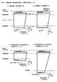
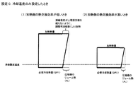
(設定A)加熱温度・冷却温度の両方を設定した場合(図3)
温水と冷水の設定の温度差が小さいときは膨張弁を開いて圧力比を小さくできるのでヒートポンプの効率(COP)が高くなり、温水と冷水の設定の温度差が大きいときは膨張弁を絞って圧力比を大きくするのでヒートポンプの効率(COP)が低くなる。
(設定B)加熱温度のみを設定した場合(図4)
冷却温度を設定しない場合には、圧縮機容量は吸熱側の熱交換効率に依存するので、その熱交換効率が低いときはスーパーヒートを適正に維持するため膨張弁を絞って圧力比を大きくするためCOPが低下するとともに冷却側の温度は低下し、その熱交換効率が高いときはスーパーヒートを適正に維持するため膨張弁を開いて圧力比を小さくするためCOPが向上するとともに、冷却側の温度は上昇する。
(Setting A) When both heating temperature and cooling temperature are set (Figure 3)
When the temperature difference between the hot water and cold water settings is small, the pressure ratio can be reduced by opening the expansion valve, so the efficiency (COP) of the heat pump increases, and when the temperature difference between the hot water and cold water settings is large, the expansion valve is throttled Since the pressure ratio is increased, the efficiency (COP) of the heat pump is lowered.
(Setting B) When only the heating temperature is set (Figure 4)
When the cooling temperature is not set, the compressor capacity depends on the heat exchange efficiency on the endothermic side, so when the heat exchange efficiency is low, the expansion valve is throttled to increase the pressure ratio in order to maintain the superheat properly. Therefore, the temperature on the cooling side decreases as the COP decreases, and when the heat exchange efficiency is high, the COP is improved to open the expansion valve and reduce the pressure ratio in order to maintain the superheat properly, and the cooling side The temperature rises.
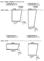
(設定C)冷却温度のみを設定した場合(図5)
加熱温度を設定しない場合には、圧縮機の圧力比は加熱側の熱交換効率に依存するので、その熱交換効率が低いときはスーパーヒートを適正に維持するため膨張弁を絞って圧力比を大きくするためCOPが低下するとともに加熱側の温度は上昇し、その熱交換効率が高いときはスーパーヒートを適正に維持するため膨張弁を開いて圧力比を小さくするためCOPが向上するとともに加熱側の温度は下がる。
(設定D)加熱温度・冷却温度とも設定しない場合(図6)
加熱側の熱交換効率が高く、冷却側の熱交換効率が高いときは、圧力比が小さくなってCOPが高くなる。加熱側の熱交換効率が低く、冷却側の熱交換効率が低いときは、圧力比が大きくなってCOPが低くなる。加熱側の熱交換効率が低く、冷却側の熱交換効率が高いときは、全体が上方にシフトする。加熱側の熱交換効率が高く、冷却側の熱交換効率が低いときは、全体が下方にシフトする。
(Setting C) When only the cooling temperature is set (Figure 5)
When the heating temperature is not set, the pressure ratio of the compressor depends on the heat exchange efficiency on the heating side, so when the heat exchange efficiency is low, the expansion valve is throttled to reduce the pressure ratio in order to maintain superheat appropriately. To increase the temperature, the COP decreases and the temperature on the heating side rises. When the heat exchange efficiency is high, the COP is improved while the expansion valve is opened to reduce the pressure ratio in order to maintain the superheat properly. The temperature drops.
(Setting D) When neither heating temperature nor cooling temperature is set (Fig. 6)
When the heat exchange efficiency on the heating side is high and the heat exchange efficiency on the cooling side is high, the pressure ratio decreases and the COP increases. When the heat exchange efficiency on the heating side is low and the heat exchange efficiency on the cooling side is low, the pressure ratio increases and the COP decreases. When the heat exchange efficiency on the heating side is low and the heat exchange efficiency on the cooling side is high, the whole shifts upward. When the heat exchange efficiency on the heating side is high and the heat exchange efficiency on the cooling side is low, the whole shifts downward.
以下に、別の構成のものを示すが、共通する部分は同じ符号を付してその説明を省略する。 Although the thing of another structure is shown below, the common part attaches | subjects the same code | symbol and abbreviate | omits the description.
図7は、本発明の第2の実施の形態に係る自律平衡型ヒートポンプユニット23の構成図である。
冷媒循環経路3に圧縮機5、凝縮器7、四方弁25、熱交換器27、膨張弁11、四方弁25、蒸発器15、圧縮機5の順に接続されている。四方弁25のON/OFF切替えにより熱交換器27を調整用凝縮器または調整用蒸発器として使い分けることができる。
調整用凝縮器と調整用蒸発器は構造や必要能力が同じで、上記の熱移動のパターンで説明したように同時には使わないので、四方弁25の切替えにより使い分けることで、低価格化及びユニットのコンパクト化を図れる。
FIG. 7 is a configuration diagram of the autonomous balanced
The
The adjusting condenser and the adjusting evaporator have the same structure and necessary capacity, and are not used at the same time as described in the above heat transfer pattern. Can be made compact.
図8は、本発明の第3の実施の形態に係る自律平衡型ヒートポンプユニット29の構成図である。
冷媒循環経路3に圧縮機5、主凝縮器7、完全開放可能な第一膨張弁31、調整用凝縮器および調整用蒸発器として兼用される熱交換器27、完全開放可能な第二膨張弁33、主蒸発器15、圧縮機5の順に接続され、第一膨張弁31と第二膨張弁33のいずれかを完全開放にすることにより、熱交換器27を調整用凝縮器または調整用蒸発器として使い分けることができる。
なお、図8の右側に示されているように、完全開放可能な膨張弁31、33の位置に、膨張弁11、11を代わりに配置し、各膨張弁11と並行して電磁弁35等の切替手段を使った開閉自在のバイパス経路37を設置することで、膨張弁11の一方を無効化してもよい。
FIG. 8 is a configuration diagram of an autonomous balanced
As shown on the right side of FIG. 8,
図9は、本発明の第4の実施の形態に係る自律平衡型ヒートポンプユニット39の構成図である。
第一主熱交換器41を主凝縮器として、第二主熱交換器43を主蒸発器として使用し、四方弁25の切替えにより、主熱交換器41を主蒸発器として、主熱交換器43を主凝縮器として使用することができる。例えば、夏と冬で使い方を逆にしたい場合に有用である。
第一膨張弁31と第二膨張弁33の有効・無効化によって、熱交換器27を調整用凝縮器または調整用蒸発器として使い分けている。
なお、この実施の形態でも、図9の右側に示されているように、完全開放可能な膨張弁31、33の位置に、膨張弁11、11を代わりに配置し、各膨張弁11と並行して電磁弁35等の切替手段を使った開閉自在のバイパス経路37を設置することで、膨張弁11の一方を無効化してもよい。但し、実際の多くの電磁弁がそうであるように方向性を持つときは、四方弁を逆にして冷媒の方向が逆になったときに、電磁弁が使えなくなるため、両方向に電磁弁を使う等の対策が必要である。
FIG. 9 is a configuration diagram of an autonomous balanced
The first
By enabling / disabling the
Also in this embodiment, as shown on the right side of FIG. 9, the
以上、本発明の実施の形態について詳述してきたが、具体的構成は、この実施の形態に限られるものではなく、本発明の要旨を逸脱しない範囲における設計の変更などがあっても発明に含まれる。
例えば、主凝縮器と調整用凝縮器は冷媒の循環方向に対して逆に配置してもよい。主蒸発器と調整用凝縮器も冷媒の循環方向に対して逆に配置してもよい。
また、二次冷媒の温度を直接監視する代わりに、冷媒状態の監視情報に基づいて推定してもよい。
また、本発明のヒートポンプユニットは、汎用型であることを最大の特徴としており、上記した冷温水の取出しだけでなく、乾燥装置や、農業ハウスの冷暖房や、水の蒸留や、工場における排熱のカスケード利用や、店舗のショーケースの適温保持等にも有用である。
また、熱交換器で熱交換する系外のものは空気に限定されず、地下水や河川水でもよい。
The embodiment of the present invention has been described in detail above. However, the specific configuration is not limited to this embodiment, and the present invention can be changed even if there is a design change without departing from the gist of the present invention. included.
For example, the main condenser and the adjusting condenser may be disposed in the opposite direction with respect to the refrigerant circulation direction. The main evaporator and the adjusting condenser may also be arranged opposite to the refrigerant circulation direction.
Further, instead of directly monitoring the temperature of the secondary refrigerant, it may be estimated based on the monitoring information of the refrigerant state.
In addition, the heat pump unit of the present invention is characterized by being a general-purpose type. Not only the above-described cold / hot water extraction, but also a drying device, an air conditioner / heater of an agricultural house, water distillation, and waste heat in a factory. It is also useful for cascade use, and for maintaining the appropriate temperature of store showcases.
Moreover, the thing outside the system which heat-exchanges with a heat exchanger is not limited to air, Ground water and river water may be sufficient.
本発明の自律平衡型ヒートポンプユニットでは、ユニットだけの作動で加熱・冷却対象を所望の温度に加熱・冷却でき、ヒートポンプユニットを組み込んだシステムが全体として複雑化せずに済む。 In the self-balancing heat pump unit of the present invention, the heating / cooling target can be heated / cooled to a desired temperature only by the operation of the unit, and the system incorporating the heat pump unit does not need to be complicated as a whole.
1…自律平衡型ヒートポンプユニット(第1の実施の形態)
2…ユニットボックス 3…冷媒循環経路
5…圧縮機 7…主凝縮器
9…調整用凝縮器 10…凝縮ファン
11…(電子)膨張弁 13…調整用蒸発器
14…蒸発ファン 15…主蒸発器
17…温水供給経路 19…冷水供給経路
21…制御手段
A〜D…冷媒温度センサー
E、F…加熱・冷却対象物温度センサー
23…自律平衡型ヒートポンプユニット(第2の実施の形態)
25…四方弁 27…放熱・吸熱兼用熱交換器
29…自律平衡型ヒートポンプユニット(第3の実施の形態)
31…第一膨張弁 33…第二膨張弁
35…電磁弁 37…バイパス経路
39…自律平衡型ヒートポンプユニット(第4の実施の形態)
41…第一主熱交換器(第4の実施の形態)
43…第二主熱交換器(第4の実施の形態)
1 ... Autonomous equilibrium heat pump unit (first embodiment)
DESCRIPTION OF
25 ... Four-
31 ...
41 ... 1st main heat exchanger (4th Embodiment)
43 ... Second main heat exchanger (fourth embodiment)
Claims (8)
前記圧縮機は容量可変で、前記膨張弁は開度可変であり、
前記冷媒循環経路に前記凝縮器と前記膨張弁との間に介挿された交換熱量可変の調整用凝縮器と、前記冷媒循環経路に前記蒸発器と前記膨張弁との間に介挿された交換熱量可変の調整用蒸発器と、膨張弁前と膨張弁後と圧縮機前と圧縮機後の位置における冷媒温度により冷媒状態を監視する冷媒状態監視手段と、前記凝縮器における熱移動によって変化する前記加熱対象の温度を監視する加熱温度監視手段と、前記蒸発器における熱移動によって変化する前記冷却対象の温度を監視する冷却温度監視手段と、前記圧縮機、前記膨張弁、前記調整用凝縮器および前記調整用蒸発器の制御により、前記加熱対象の温度と前記冷却対象の温度を目標範囲に収める制御手段とを備え、
前記制御手段により、冷凍サイクル内の放熱熱量と吸熱熱量を自律的に平衡させると共に、前記加熱対象と前記冷却対象の温度がそれぞれ設定した目標範囲になるように、前記圧縮機と前記膨張弁と前記調整用凝縮器と前記調整用蒸発器を制御することを特徴とするヒートポンプユニット。 It is composed of a vapor compression refrigeration cycle in which a compressor, a condenser, an expansion valve, and an evaporator are inserted in the refrigerant circulation path, and is used as a component of the external system to be heated by the external system. In an autonomous equilibrium heat pump unit that can control the temperature of the object and the temperature of the cooling target side independently at the same time ,
The compressor has a variable capacity, and the expansion valve has a variable opening.
An adjustment condenser with variable exchange heat quantity inserted between the condenser and the expansion valve in the refrigerant circulation path, and inserted between the evaporator and the expansion valve in the refrigerant circulation path. Variable amount of exchange heat adjustment evaporator, refrigerant state monitoring means for monitoring refrigerant state according to refrigerant temperature at positions before expansion valve, after expansion valve, before compressor, and after compressor , and change by heat transfer in said condenser Heating temperature monitoring means for monitoring the temperature of the heating object, cooling temperature monitoring means for monitoring the temperature of the cooling object that changes due to heat transfer in the evaporator, the compressor , the expansion valve, and the adjusting condensation And a control means for keeping the temperature of the heating object and the temperature of the cooling object within a target range by controlling the evaporator and the adjusting evaporator ,
By the control means and autonomously to balance the heat radiating heat and endothermic heat in the refrigerant cycle, wherein as the temperature of the heat target and the cool target is the target range set respectively, said compressor and said expansion valve A heat pump unit that controls the adjusting condenser and the adjusting evaporator .
凝縮器または蒸発器は冷媒と水やブライン等の二次冷媒との間で熱交換を行う熱交換器であり、加熱対象または冷却対象との間に二次冷媒を循環させて間接的に熱交換を行うことを特徴とするヒートポンプユニット。 In the autonomous balanced heat pump unit according to claim 1,
A condenser or evaporator is a heat exchanger that exchanges heat between a refrigerant and a secondary refrigerant such as water or brine, and indirectly heats by circulating the secondary refrigerant between the object to be heated or cooled. A heat pump unit characterized by exchanging.
1つの熱交換器を調整用凝縮器または調整用蒸発器として択一的に使い分けることを特徴とするヒートポンプユニット。 In the autonomous balanced heat pump unit according to claim 1 or 2,
A heat pump unit characterized in that one heat exchanger is selectively used as a regulating condenser or a regulating evaporator.
冷媒循環経路に、調整用凝縮器と調整用蒸発器を兼用できる1つの調整用熱交換器と、四方弁を介挿し、前記四方弁の切替えにより前記調整用熱交換器を前記調整用凝縮器または調整用蒸発器として利用することを特徴とするヒートポンプユニット。 In the autonomous balanced heat pump unit according to claim 3,
One adjustment heat exchanger that can serve both as an adjustment condenser and an adjustment evaporator and a four-way valve are inserted in the refrigerant circulation path, and the adjustment heat exchanger is connected to the adjustment condenser by switching the four-way valve. Alternatively, the heat pump unit is used as an adjustment evaporator.
冷媒循環経路に圧縮機、凝縮器、四方弁、調整用凝縮器および調整用蒸発器として兼用される熱交換器、膨張弁、前記四方弁、蒸発器、圧縮機の順に接続されてなり、前記1つの四方弁の切替えにより、前記熱交換器を調整用凝縮器または調整用蒸発器として利用することを特徴とするヒートポンプユニット。 In the autonomous balanced heat pump unit according to claim 4,
The refrigerant circulation path is connected in the order of the compressor, the condenser, the four-way valve, the adjustment condenser and the adjustment evaporator, the heat exchanger, the expansion valve, the four-way valve, the evaporator, and the compressor. A heat pump unit using the heat exchanger as an adjustment condenser or an adjustment evaporator by switching one four-way valve.
冷媒循環経路に圧縮機、凝縮器、第一膨張弁、調整用凝縮器および調整用蒸発器として兼用される熱交換器、第二膨張弁、蒸発器、圧縮機の順に接続され、且つ前記第一膨張弁と第二膨張弁に並行してそれぞれ開閉自在なバイパス路が設けられてなり、前記バイパス路の一方を開閉することにより、前記熱交換器を調整用凝縮器または調整用蒸発器として利用することを特徴とするヒートポンプユニット。 In the autonomous balanced heat pump unit according to claim 3,
The refrigerant circulation path is connected in the order of the compressor, the condenser, the first expansion valve, the adjustment condenser, and the adjustment evaporator and the heat exchanger, the second expansion valve, the evaporator, and the compressor. A bypass passage that can be opened and closed in parallel is provided in parallel with the first expansion valve and the second expansion valve. By opening and closing one of the bypass passages, the heat exchanger can be used as an adjustment condenser or an adjustment evaporator. A heat pump unit characterized by being used.
冷媒循環経路に圧縮機、凝縮器、完全開放可能な第一膨張弁、調整用凝縮器および調整用蒸発器として兼用される熱交換器、完全開放可能な第二膨張弁、蒸発器、圧縮機の順に接続され、第一膨張弁と第二膨張弁のいずれかを完全開放にすることにより、前記熱交換器を調整用凝縮器または調整用蒸発器として利用することを特徴とするヒートポンプユニット。 In the autonomous balanced heat pump unit according to claim 3,
Compressor, condenser, first expansion valve that can be fully opened in the refrigerant circulation path, heat exchanger that can also be used as a condenser for adjustment and an evaporator for adjustment, second expansion valve that can be fully opened, evaporator, compressor A heat pump unit characterized in that the heat exchanger is used as an adjustment condenser or an adjustment evaporator by connecting either of the first expansion valve and the second expansion valve completely in order.
冷媒循環経路の圧縮機と凝縮器の間に四方弁を配置し、蒸発器と圧縮機の間に前記四方弁の戻り側を配置し、前記四方弁を切り替えることにより、前記凝縮器と前記蒸発器の機能を相互に反転して利用可能なことを特徴とするヒートポンプユニット。 In the autonomous balanced heat pump unit according to claim 6 or 7,
A four-way valve is arranged between the compressor and the condenser in the refrigerant circulation path, a return side of the four-way valve is arranged between the evaporator and the compressor, and the four-way valve is switched to thereby switch the condenser and the evaporation. The heat pump unit is characterized in that it can be used by reversing the functions of the vessel.
Priority Applications (1)
| Application Number | Priority Date | Filing Date | Title |
|---|---|---|---|
| JP2009090012A JP5474397B2 (en) | 2009-04-02 | 2009-04-02 | Autonomous equilibrium heat pump unit |
Applications Claiming Priority (1)
| Application Number | Priority Date | Filing Date | Title |
|---|---|---|---|
| JP2009090012A JP5474397B2 (en) | 2009-04-02 | 2009-04-02 | Autonomous equilibrium heat pump unit |
Publications (2)
| Publication Number | Publication Date |
|---|---|
| JP2010243001A JP2010243001A (en) | 2010-10-28 |
| JP5474397B2 true JP5474397B2 (en) | 2014-04-16 |
Family
ID=43096192
Family Applications (1)
| Application Number | Title | Priority Date | Filing Date |
|---|---|---|---|
| JP2009090012A Expired - Fee Related JP5474397B2 (en) | 2009-04-02 | 2009-04-02 | Autonomous equilibrium heat pump unit |
Country Status (1)
| Country | Link |
|---|---|
| JP (1) | JP5474397B2 (en) |
Families Citing this family (13)
| Publication number | Priority date | Publication date | Assignee | Title |
|---|---|---|---|---|
| CN105505323A (en) * | 2008-03-07 | 2016-04-20 | 阿科玛股份有限公司 | Halogenated alkene heat transfer composition with improved oil return |
| CN102128509B (en) * | 2011-02-25 | 2013-01-30 | 合肥美的荣事达电冰箱有限公司 | Low-noise refrigerating system and refrigerating method thereof |
| JP2012242020A (en) * | 2011-05-20 | 2012-12-10 | Denso Corp | Heat pump apparatus |
| JP2013057467A (en) * | 2011-09-09 | 2013-03-28 | Science Kk | Waste heat recovery type heat pump |
| CN103574960A (en) * | 2012-08-08 | 2014-02-12 | 昆山赤子坊国际贸易有限公司 | Novel refrigeration device |
| JP2014088975A (en) * | 2012-10-29 | 2014-05-15 | Orion Mach Co Ltd | Heating/cooling device |
| CN103075843A (en) * | 2013-01-21 | 2013-05-01 | 深圳市庄合地能产业科技有限公司 | Hot and cold inner balance set |
| CN103090591A (en) * | 2013-01-21 | 2013-05-08 | 深圳市庄合地能产业科技有限公司 | Cold and hot internal balance system for combined use of lithium bromide unit and refrigeration storage |
| JP2015152183A (en) * | 2014-02-10 | 2015-08-24 | リンナイ株式会社 | heat pump |
| JP6485390B2 (en) * | 2016-03-08 | 2019-03-20 | 株式会社デンソー | Refrigeration cycle equipment |
| CN110763495B (en) * | 2019-10-12 | 2021-04-30 | 中国北方车辆研究所 | A method for judging the performance of a pump drive motor in a test system |
| KR102402683B1 (en) * | 2020-01-29 | 2022-05-25 | 김병우 | Vacuum dryer without vacuum pump |
| CN113587472A (en) * | 2021-07-08 | 2021-11-02 | 中国科学院理化技术研究所 | Cascade heat pump system |
Family Cites Families (6)
| Publication number | Priority date | Publication date | Assignee | Title |
|---|---|---|---|---|
| JPH0755282A (en) * | 1993-08-20 | 1995-03-03 | Fujitsu General Ltd | Air conditioner |
| JP2002372320A (en) * | 2001-06-15 | 2002-12-26 | Matsushita Electric Ind Co Ltd | Refrigeration equipment |
| JP2009052880A (en) * | 2004-03-29 | 2009-03-12 | Mitsubishi Electric Corp | Heat pump water heater |
| JP4481893B2 (en) * | 2005-07-08 | 2010-06-16 | 株式会社グリーンセイジュ | Drying system |
| JP2008185245A (en) * | 2007-01-29 | 2008-08-14 | Osaka Gas Co Ltd | Compression heat pump device, operation method of compression heat pump device, and cogeneration system |
| JP5194619B2 (en) * | 2007-08-02 | 2013-05-08 | 富士電機株式会社 | Cooling and heating device |
-
2009
- 2009-04-02 JP JP2009090012A patent/JP5474397B2/en not_active Expired - Fee Related
Also Published As
| Publication number | Publication date |
|---|---|
| JP2010243001A (en) | 2010-10-28 |
Similar Documents
| Publication | Publication Date | Title |
|---|---|---|
| JP5474397B2 (en) | Autonomous equilibrium heat pump unit | |
| JP3858015B2 (en) | Refrigerant circuit and heat pump water heater | |
| CA2745109C (en) | Heat pump/air conditioning apparatus with sequential operation | |
| JP3997482B2 (en) | Water source air conditioning system | |
| CN106322595A (en) | Refrigeration and dehumidification system, refrigeration and dehumidification method and refrigeration and dehumidification air conditioner for data centres | |
| JP2018036002A (en) | Air conditioning and hot water supply system | |
| CN106839498A (en) | Heat pump air conditioner and its control method | |
| JP2012202624A (en) | Refrigeration cycle apparatus | |
| JP5693990B2 (en) | Air source heat pump air conditioner | |
| KR101148714B1 (en) | Heat-pump system | |
| KR20120125856A (en) | Heat storaging apparatus having cascade cycle and Control process of the same | |
| CN100593099C (en) | Air conditioner | |
| JP2003232581A (en) | Air conditioner | |
| KR101127758B1 (en) | Hot and cool water, heating and cooling supply system | |
| KR100779555B1 (en) | Regenerative heat pump system with heat source temperature compensation circuit | |
| KR101446921B1 (en) | heat pump type coolin/heating system with hybrid heat exchanger | |
| JP5333557B2 (en) | Hot water supply air conditioning system | |
| JP2010243005A (en) | Dehumidification system | |
| JP4097405B2 (en) | Engine cooling method and apparatus and refrigeration apparatus | |
| JP2006145098A (en) | Thermal storage air conditioner | |
| JP7221541B2 (en) | outside air conditioner | |
| KR20140133375A (en) | Two stage heat pump cooling and heating apparatus using air heat source | |
| KR101201212B1 (en) | Gas engine heat pump | |
| JP2015124908A (en) | Hot water supply air-conditioning system | |
| JPH0776628B2 (en) | Air-conditioning dehumidification system |
Legal Events
| Date | Code | Title | Description |
|---|---|---|---|
| A621 | Written request for application examination |
Free format text: JAPANESE INTERMEDIATE CODE: A621 Effective date: 20111130 |
|
| A977 | Report on retrieval |
Free format text: JAPANESE INTERMEDIATE CODE: A971007 Effective date: 20130129 |
|
| A131 | Notification of reasons for refusal |
Free format text: JAPANESE INTERMEDIATE CODE: A131 Effective date: 20130207 |
|
| A521 | Written amendment |
Free format text: JAPANESE INTERMEDIATE CODE: A523 Effective date: 20130402 |
|
| A02 | Decision of refusal |
Free format text: JAPANESE INTERMEDIATE CODE: A02 Effective date: 20130819 |
|
| A521 | Written amendment |
Free format text: JAPANESE INTERMEDIATE CODE: A523 Effective date: 20131115 |
|
| A911 | Transfer of reconsideration by examiner before appeal (zenchi) |
Free format text: JAPANESE INTERMEDIATE CODE: A911 Effective date: 20131122 |
|
| TRDD | Decision of grant or rejection written | ||
| A01 | Written decision to grant a patent or to grant a registration (utility model) |
Free format text: JAPANESE INTERMEDIATE CODE: A01 Effective date: 20140128 |
|
| A61 | First payment of annual fees (during grant procedure) |
Free format text: JAPANESE INTERMEDIATE CODE: A61 Effective date: 20140205 |
|
| R150 | Certificate of patent or registration of utility model |
Ref document number: 5474397 Country of ref document: JP Free format text: JAPANESE INTERMEDIATE CODE: R150 Free format text: JAPANESE INTERMEDIATE CODE: R150 |
|
| R250 | Receipt of annual fees |
Free format text: JAPANESE INTERMEDIATE CODE: R250 |
|
| R250 | Receipt of annual fees |
Free format text: JAPANESE INTERMEDIATE CODE: R250 |
|
| R250 | Receipt of annual fees |
Free format text: JAPANESE INTERMEDIATE CODE: R250 |
|
| LAPS | Cancellation because of no payment of annual fees |