JP5471886B2 - High temperature, high pressure processing method, high temperature, high pressure processing apparatus and storage medium - Google Patents
High temperature, high pressure processing method, high temperature, high pressure processing apparatus and storage medium Download PDFInfo
- Publication number
- JP5471886B2 JP5471886B2 JP2010145466A JP2010145466A JP5471886B2 JP 5471886 B2 JP5471886 B2 JP 5471886B2 JP 2010145466 A JP2010145466 A JP 2010145466A JP 2010145466 A JP2010145466 A JP 2010145466A JP 5471886 B2 JP5471886 B2 JP 5471886B2
- Authority
- JP
- Japan
- Prior art keywords
- organic solvent
- temperature
- ipa
- pressure
- concentration
- Prior art date
- Legal status (The legal status is an assumption and is not a legal conclusion. Google has not performed a legal analysis and makes no representation as to the accuracy of the status listed.)
- Active
Links
- 238000003860 storage Methods 0.000 title claims description 48
- 238000000034 method Methods 0.000 title claims description 46
- 238000009931 pascalization Methods 0.000 title claims description 25
- KFZMGEQAYNKOFK-UHFFFAOYSA-N Isopropanol Chemical compound CC(C)O KFZMGEQAYNKOFK-UHFFFAOYSA-N 0.000 claims description 535
- 238000012545 processing Methods 0.000 claims description 122
- 239000003960 organic solvent Substances 0.000 claims description 63
- XLYOFNOQVPJJNP-UHFFFAOYSA-N water Substances O XLYOFNOQVPJJNP-UHFFFAOYSA-N 0.000 claims description 63
- 239000012530 fluid Substances 0.000 claims description 22
- 238000011084 recovery Methods 0.000 claims description 7
- 238000004590 computer program Methods 0.000 claims description 4
- 239000007788 liquid Substances 0.000 description 84
- 235000012431 wafers Nutrition 0.000 description 76
- 239000007789 gas Substances 0.000 description 22
- 238000004140 cleaning Methods 0.000 description 17
- 238000001514 detection method Methods 0.000 description 17
- 238000001816 cooling Methods 0.000 description 15
- 238000012546 transfer Methods 0.000 description 14
- 238000010926 purge Methods 0.000 description 12
- 239000012528 membrane Substances 0.000 description 10
- 239000000243 solution Substances 0.000 description 9
- 238000005259 measurement Methods 0.000 description 8
- 239000002245 particle Substances 0.000 description 8
- 238000001223 reverse osmosis Methods 0.000 description 8
- 238000001035 drying Methods 0.000 description 6
- 238000010521 absorption reaction Methods 0.000 description 5
- 239000008367 deionised water Substances 0.000 description 5
- 229910021641 deionized water Inorganic materials 0.000 description 5
- 239000000126 substance Substances 0.000 description 5
- 238000011144 upstream manufacturing Methods 0.000 description 5
- KRHYYFGTRYWZRS-UHFFFAOYSA-N Fluorane Chemical compound F KRHYYFGTRYWZRS-UHFFFAOYSA-N 0.000 description 4
- 239000011261 inert gas Substances 0.000 description 4
- 238000005260 corrosion Methods 0.000 description 3
- 230000007797 corrosion Effects 0.000 description 3
- 230000007423 decrease Effects 0.000 description 3
- 238000010586 diagram Methods 0.000 description 3
- XTUSEBKMEQERQV-UHFFFAOYSA-N propan-2-ol;hydrate Chemical compound O.CC(C)O XTUSEBKMEQERQV-UHFFFAOYSA-N 0.000 description 3
- QGZKDVFQNNGYKY-UHFFFAOYSA-N Ammonia Chemical compound N QGZKDVFQNNGYKY-UHFFFAOYSA-N 0.000 description 2
- CURLTUGMZLYLDI-UHFFFAOYSA-N Carbon dioxide Chemical compound O=C=O CURLTUGMZLYLDI-UHFFFAOYSA-N 0.000 description 2
- 230000002378 acidificating effect Effects 0.000 description 2
- 239000000470 constituent Substances 0.000 description 2
- 239000000498 cooling water Substances 0.000 description 2
- 238000007599 discharging Methods 0.000 description 2
- 230000007717 exclusion Effects 0.000 description 2
- 239000011521 glass Substances 0.000 description 2
- 238000010438 heat treatment Methods 0.000 description 2
- 239000000203 mixture Substances 0.000 description 2
- 230000001590 oxidative effect Effects 0.000 description 2
- BDERNNFJNOPAEC-UHFFFAOYSA-N propan-1-ol Chemical compound CCCO BDERNNFJNOPAEC-UHFFFAOYSA-N 0.000 description 2
- 229910052594 sapphire Inorganic materials 0.000 description 2
- 239000010980 sapphire Substances 0.000 description 2
- 239000004065 semiconductor Substances 0.000 description 2
- MHAJPDPJQMAIIY-UHFFFAOYSA-N Hydrogen peroxide Chemical compound OO MHAJPDPJQMAIIY-UHFFFAOYSA-N 0.000 description 1
- 238000009825 accumulation Methods 0.000 description 1
- 230000002411 adverse Effects 0.000 description 1
- 229910021529 ammonia Inorganic materials 0.000 description 1
- 239000007864 aqueous solution Substances 0.000 description 1
- 229910002092 carbon dioxide Inorganic materials 0.000 description 1
- 239000001569 carbon dioxide Substances 0.000 description 1
- 230000003247 decreasing effect Effects 0.000 description 1
- 239000000428 dust Substances 0.000 description 1
- 230000000694 effects Effects 0.000 description 1
- 238000001704 evaporation Methods 0.000 description 1
- 230000008020 evaporation Effects 0.000 description 1
- 239000012510 hollow fiber Substances 0.000 description 1
- 239000012535 impurity Substances 0.000 description 1
- 230000001678 irradiating effect Effects 0.000 description 1
- 238000012423 maintenance Methods 0.000 description 1
- 238000004519 manufacturing process Methods 0.000 description 1
- 230000003287 optical effect Effects 0.000 description 1
- 230000002093 peripheral effect Effects 0.000 description 1
- 239000002957 persistent organic pollutant Substances 0.000 description 1
- 238000000926 separation method Methods 0.000 description 1
- 238000004804 winding Methods 0.000 description 1
Images


Description
本発明は、被処理体に対して有機溶媒を含む流体を高温、高圧状態にして処理を行う技術に関する。 TECHNICAL FIELD The present invention relates to a technique for performing processing on a workpiece by putting a fluid containing an organic solvent in a high temperature and high pressure state.
半導体装置の製造工程などにおいては、洗浄処理等、液体を利用してウエハ表面を処理する液処理工程が設けられている。例えば枚葉式のスピン洗浄装置では、ウエハ表面に例えばアルカリ性や酸性の薬液を供給しながらウエハを回転させることによってウエハ表面のごみや自然酸化物などを除去する。そして、この後、例えば純水などによるリンス洗浄を行い、最後にウエハを回転させることによって、残った液体を振り飛ばす振切乾燥などが行われる。 In the manufacturing process of a semiconductor device, etc., a liquid processing process for processing the wafer surface using a liquid, such as a cleaning process, is provided. For example, in a single wafer spin cleaning apparatus, dust or natural oxides on the wafer surface are removed by rotating the wafer while supplying, for example, alkaline or acidic chemicals to the wafer surface. Thereafter, rinsing with, for example, pure water is performed, and finally the wafer is rotated to perform shake-off drying to shake off the remaining liquid.
ところが、半導体装置の高集積化に伴い、こうしたウエハW表面に残った液体を除去する処理において、いわゆるパターン倒れの問題が大きくなってきている。このパターン倒れは、ウエハW表面のパターンを形成する凹凸において、例えば凸部の左右に残っている液体が不均一に乾燥することにより、この凸部を左右に引っ張る表面張力のバランスが崩れて液体の多く残っている方向に凸部が倒れる現象である。 However, as semiconductor devices are highly integrated, the problem of so-called pattern collapse is increasing in the process of removing the liquid remaining on the surface of the wafer W. This pattern collapse is caused by the unevenness that forms the pattern on the surface of the wafer W. For example, the liquid remaining on the left and right sides of the protrusions is dried unevenly, so that the balance of the surface tension that pulls the protrusions left and right is lost. This is a phenomenon in which the convex part collapses in the direction in which many remain.
こうしたパターン倒れを抑えつつウエハ表面に残った液体を除去する手法として超臨界状態の流体(超臨界流体)を用いた乾燥方法が知られている。超臨界流体は、液体と比べて粘度が小さく、また液体を溶解する能力も高いことに加え、超臨界流体と平衡状態にある液体や気体との間で界面が存在しない。そこで、液体の付着した状態のウエハを超臨界流体と置換し、しかる後、超臨界流体を気体に状態変化させると、表面張力の影響を受けることなく液体を乾燥させることができる。 A drying method using a supercritical fluid (supercritical fluid) is known as a technique for removing the liquid remaining on the wafer surface while suppressing such pattern collapse. The supercritical fluid has a smaller viscosity than the liquid and has a high ability to dissolve the liquid, and there is no interface between the supercritical fluid and the liquid or gas in an equilibrium state. Therefore, the liquid can be dried without being affected by the surface tension by replacing the wafer on which the liquid is adhered with the supercritical fluid and then changing the state of the supercritical fluid to a gas.
超臨界流体としては、例えばイソプロピルアルコール(IPA)が用いられる。前記乾燥処理では、高圧容器に収納されたウエハWに対してIPAを供給し、容器内のIPAを高温、高圧化にすることによって、IPAの超臨界流体を発生させ、ウエハW上の液体と置換させる。そして、温度を維持したまま減圧することにより、超臨界状態にあるIPAを気化し、こうして液体を乾燥させている。 For example, isopropyl alcohol (IPA) is used as the supercritical fluid. In the drying process, IPA is supplied to the wafer W accommodated in the high-pressure container, and the IPA in the container is heated to a high temperature and pressure to generate a supercritical fluid of the IPA. Replace. Then, by reducing the pressure while maintaining the temperature, IPA in a supercritical state is vaporized, and thus the liquid is dried.
前記IPAとしては、IPA供給源から未使用の新鮮なIPAを高圧容器に直接供給する場合や、高圧容器から回収されたものを再利用する場合がある。前記IPAは吸湿性が大きく、大気と接触すると大気中の水分を吸収してしまうため、未使用のIPAを用いる場合であっても、水分濃度は安定していない。一方、回収されたIPAを再利用する場合には、IPAはウエハW上の水分を吸収しているため、未使用のIPAよりも水分濃度が高い状態である。 As the IPA, fresh IPA that is unused from an IPA supply source may be directly supplied to the high-pressure vessel, or the IPA recovered from the high-pressure vessel may be reused. Since the IPA has high hygroscopicity and absorbs moisture in the atmosphere when it comes into contact with the atmosphere, the moisture concentration is not stable even when unused IPA is used. On the other hand, when the collected IPA is reused, the IPA absorbs the moisture on the wafer W, and therefore has a higher moisture concentration than the unused IPA.
ところで、前記乾燥処理では、高圧容器の内部を、270℃、7MPaの高温、高圧状態に設定することにより、IPAを超臨界状態に変化させている。この際、IPA中の水分も高温、高圧状態となり、極めて大きい腐食性(酸化力)を有するものになることが認められている。市販されているIPAの純度は99.9重量%以上であり、不純物としては、水分やn−プロピルアルコールを含んでいる。従って、未使用のIPAを用いる場合であっても、使用するまでに水分を吸収して水分濃度が更に高くなるおそれもある。このように水分濃度が安定しないIPAを超臨界状態にしてウエハWに供給すると、ウエハパターンや、処理装置を腐食させてしまう懸念がある。 By the way, in the said drying process, IPA is changed to a supercritical state by setting the inside of a high pressure container to 270 degreeC, the high temperature of 7 MPa, and a high pressure state. At this time, it is recognized that the water in the IPA is also in a high temperature and high pressure state and has extremely high corrosiveness (oxidizing power). Commercially available IPA has a purity of 99.9% by weight or more and contains moisture and n-propyl alcohol as impurities. Therefore, even when unused IPA is used, there is a possibility that the moisture concentration is further increased by absorbing moisture before use. Thus, when IPA whose moisture concentration is not stable is supplied to the wafer W in a supercritical state, there is a concern that the wafer pattern and the processing apparatus may be corroded.
ここで、特許文献1には、ガス分離膜を用いて、IPAの水分含有率を減少する手法について記載されている。この手法によれば、当該特許文献1の実施例に記載されるように、IPA濃度が99.5重量%、水分濃度が0.5重量%程度にまで水分含有率を減少することができるが、上述の懸念は払拭されない。 Here, Patent Document 1 describes a technique for reducing the moisture content of IPA using a gas separation membrane. According to this method, the water content can be reduced to an IPA concentration of 99.5% by weight and a water concentration of about 0.5% by weight, as described in the example of the patent document 1. The above concerns are not dispelled.
本発明はこのような事情に鑑みてなされたものであり、その目的は、水分濃度が低い有機溶媒を処理部又は被処理体に供給して処理を行うことにより、被処理体や処理部の腐食を抑えることができる高温、高圧処理方法及び高温、高圧処理装置を提供することにある。 This invention is made | formed in view of such a situation, The objective is supplying an organic solvent with low moisture concentration to a process part or a to-be-processed object, and performing a process, A to-be-processed object or a process part is carried out. The object is to provide a high-temperature and high-pressure treatment method and a high-temperature and high-pressure treatment apparatus capable of suppressing corrosion.
このため、本発明の高温高圧処理方法は、
有機溶媒の供給源から供給された有機溶媒に含まれる水分を除去する工程と、
次いでこの水分が除去された有機溶媒の水分濃度を測定する工程と、
前記水分濃度の測定値が設定濃度以下になった有機溶媒を高温、高圧化し、高温、高圧状態とされた有機溶媒を含む流体により処理チャンバ内にて被処理体を処理する工程と、を含み、
前記設定濃度は、0.01重量%以下であることを特徴とする。
Therefore, the high-temperature and high-pressure treatment method of the present invention is
Removing water contained in the organic solvent supplied from the organic solvent source;
Next, measuring the water concentration of the organic solvent from which the water has been removed,
Treating the object to be processed in a processing chamber with a fluid containing the organic solvent at a high temperature and a high pressure, and increasing the pressure of the organic solvent whose measured value of the moisture concentration is equal to or lower than a set concentration. ,
The set concentration is 0.01% by weight or less.
また、本発明の高温高圧処理装置は、
有機溶媒を高温、高圧化するための機構と、
前記高温、高圧化された有機溶媒により被処理体を処理するための処理チャンバと、
前記有機溶媒の供給源と
この供給源から供給された有機溶媒に含まれる水分を除去するための水分除去部と、
この水分除去部で水分が除去された有機溶媒の水分濃度を測定する濃度測定部と、
前記濃度測定部における水分濃度の測定値が設定濃度以下になった有機溶媒を高温、高圧化するように制御信号を出力する制御部と、を備え、
前記設定濃度は、0.01重量%以下であることを特徴とする。
Moreover, the high-temperature and high-pressure treatment apparatus of the present invention is
A mechanism for increasing the temperature and pressure of organic solvents;
A processing chamber for processing an object to be processed with the high-temperature, high-pressure organic solvent ;
A supply source of the organic solvent, and a moisture removing unit for removing moisture contained in the organic solvent supplied from the supply source;
A concentration measuring unit for measuring the moisture concentration of the organic solvent from which moisture has been removed by the moisture removing unit;
And a control unit for outputting a control signal to the high temperature, high pressure organic solvent measured value is below the set concentration of the water concentration in the concentration measuring unit,
The set concentration is 0.01% by weight or less.
さらに、本発明の記憶媒体は、水分濃度が0.01重量%以下の有機溶媒を含む流体を高温、高圧状態にして被処理体に対して処理を行うことを特徴とする高温、高圧処理装置に用いられるコンピュータプログラムを記憶する記憶媒体であって、
前記コンピュータプログラムは、前記高温、高圧処理方法を実施するためのステップ群が組み込まれていることを特徴とする。
Furthermore, the storage medium of the present invention is a high-temperature and high-pressure processing apparatus characterized in that a fluid containing an organic solvent having a moisture concentration of 0.01% by weight or less is processed at a high temperature and high pressure to treat a target object. A storage medium for storing a computer program used for
The computer program includes a group of steps for carrying out the high temperature and high pressure processing method.
本発明によれば、有機溶媒の供給源からの有機溶媒に対して予め水分の除去処理を行い、水分濃度が0.01重量%以下の設定値よりも低くなったときに、当該有機溶媒を処理部又は被処理体に供給するようにしている。このため、処理部にて有機溶媒を含む流体を高温、高圧化したときに、有機溶媒と共に高温、高圧状態となる水分が極めて少ないので、被処理体や処理部の腐食を抑えることができる。 According to the present invention, when the organic solvent from the organic solvent supply source is subjected to moisture removal treatment in advance and the water concentration becomes lower than the set value of 0.01% by weight or less, the organic solvent is added. It supplies to a process part or a to-be-processed object. For this reason, when a fluid containing an organic solvent is heated to a high temperature and a high pressure in the processing section, the amount of water that becomes a high temperature and high pressure state together with the organic solvent is extremely small, so that corrosion of the object to be processed and the processing section can be suppressed.
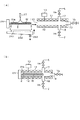
以下、本発明の高温、高圧処理方法を実施する高温、高圧処理装置をなす超臨界処理装置1の一実施の形態について、図1及び図2を参照して説明する。ここでは、有機溶媒としてIPAを用い、このIPAを高温、高圧化して超臨界流体を生成し、この超臨界流体を用いてウエハWを乾燥する処理を行う場合を例にして説明する。図1中、11は、高温、高圧処理である超臨界処理を行う処理チャンバであり、この処理チャンバ11には、外部の搬送アームとの間でウエハWの受け渡しを行うウエハホルダ2により、ウエハWの搬入出が行われるようになっている。
Hereinafter, an embodiment of a supercritical processing apparatus 1 constituting a high temperature and high pressure processing apparatus for carrying out the high temperature and high pressure processing method of the present invention will be described with reference to FIG. 1 and FIG. Here, a case will be described as an example where IPA is used as the organic solvent, the IPA is heated to high temperature and pressure to generate a supercritical fluid, and the wafer W is dried using the supercritical fluid. In FIG. 1,
前記処理チャンバ11は耐圧容器からなり、その前面には、ウエハWを搬入出するための開口部110が形成され、前記ウエハホルダ2にウエハWを保持した状態でウエハWを格納するように構成されている。このような処理チャンバ11の上下両面には、例えばテープヒーターなどの抵抗発熱体からなるヒータ12が設けられており、電源部13の出力を増減することにより、処理空間の温度を調整することができるように構成されている。
The
図1中14及び15は、処理チャンバ11の上下面に設けられた上プレート及び下プレートである。前記下プレート15の両端縁の上面側には、ウエハホルダ2を保持するアーム部材21を走行させるためのレール22が前後方向に伸びるように設けられている。図中23はスライダ、24は例えばロッドレスシリンダなどからなる駆動機構である
ウエハホルダ2は蓋部材25に接続されており、この蓋部材25は、ウエハホルダ12を処理チャンバ11の処理空間内に搬入したとき、前記開口部110を塞ぐことができるように構成されている。ここで蓋部材25と処理チャンバ11側の側壁面には、開口部110を囲むように不図示のOリングが設けられており、処理空間内の気密が維持されるようになっている。
In FIG. 1,
蓋部材25の左右両端には前記アーム部材21が設けられており、このアーム部材21の先端部を既述のスライダ23と接続することにより、前記レール22に沿ってアーム部材21を走行させることができる。こうして、ウエハホルダ2は、外部の搬送アームとの間でウエハWの受け渡しが行われる受け渡し位置(図1、図2(a)に示す位置)と、処理チャンバ11内の処理位置(図2(b)に示す位置)との間で、移動自在に構成されている。
The
また、図1中26は、前記受け渡し位置まで移動したウエハホルダ2の下方側に設けられた冷却機構であり、この冷却機構26は、例えばクーリングプレート261から冷却用の清浄空気を吐出してウエハホルダ2を冷却するように構成されている。図中262はドレイン受け皿、263はドレイン管、264はドレイン受け皿262及びクーリングプレート261を昇降させる昇降機構である。
1 is a cooling mechanism provided on the lower side of the
さらに、前記受け渡し位置の上方側には、ウエハホルダ2に受け渡されたウエハWに有機溶媒であるIPAを供給するためのIPAノズル27が設けられている。また、例えば処理チャンバ11の側壁面には、処理空間に液体の状態でIPAを供給するための供給ライン17と、処理空間にパージガスである不活性ガス例えばN2ガスを供給するためのパージガス供給路28が接続されている。この供給ライン17の上流側は後述するIPAの供給路に接続されており、既述のヒータ12の作用と相俟って、処理チャンバ11内を高温、高圧化して、超臨界状態のIPA雰囲気を形成する。
Further, an
また、図1中18は、処理雰囲気内のIPAを排出するための排出ラインであり、その下流側は後述するIPAの排出路に接続されている。さらに、処理チャンバ11の側壁面には、処理空間の内部雰囲気を排出するための排気ライン19が設けられている。これら供給ライン17、排出ライン18、排気ライン19には、図2に示すように、夫々開閉バルブVa,Vb,Vcが設けられている。なお、図2においては、図示の便宜上、供給ライン17を処理チャンバ11の上方側、排出ライン18を処理チャンバ11の下方側に記載している。また、前記パージガス供給路28は、パージガスであるN2ガスの供給源29に開閉バルブVdを介して接続されている(図3参照)。この例では、処理チャンバ11とウエハホルダ2とにより、処理部が構成されている。
Further,
続いて、この処理チャンバ11の内部とウエハホルダ2上に受け渡されたウエハWに対してIPAを供給する供給系について図3を参照して説明する。図3中、3は第1の貯留部をなす貯留タンクであり、この貯留タンク3には、例えば5リットルのIPA液が貯留できるようになっている。この貯留タンク3の上流側には、開閉バルブV1を備えた供給路31を介して、IPAの供給源30が接続されている。この供給源30には、未使用の新鮮なIPA液が貯留されている。
Next, a supply system for supplying IPA to the inside of the
また、前記貯留タンク3には、ポンプP1によりIPA液が循環供給される循環路32が接続されている。この循環路32には、例えば貯留タンク3からポンプP1、パーティクル除去フィルタF1、水分除去フィルタ4、濃度測定部5、流量調整バルブV2がこの順序で設けられている。水分除去フィルタ4、濃度測定部5については後述する。
The storage tank 3 is connected to a
さらに、この貯留タンク3には、パージガスである不活性ガス例えばN2ガスを供給するためのパージガス供給源33が、開閉バルブV3を備えた供給路34を介して接続されている。このパージガスは、IPA液が大気に接触すると、大気中の水分を吸収してしまうため、IPA液が大気と接触しないように供給される。さらにまた、貯留タンク3には、IPA液の液面レベルを検出するレベル検出部35a,35bが設けられている。前記レベル検出部35aは液面が上限レベル以上になったときに、制御部8に検出信号a1を出力し、レベル検出部35bは液面が下限レベル以下になったときに、前記制御部8に検出信号a2を出力するように構成されている。
Further, a purge
さらに、この循環路32は、濃度測定部5と流量調整バルブV32との間から分岐すると共に、開閉バルブV4を備えた供給路61により、第2の貯留部をなす中間タンク6に接続されている。この中間タンク6は、水分濃度が設定濃度以下のIPA液を貯留するタンクであり、例えば1リットル程度のIPA液が貯留されるように構成されている。ここで、前記設定濃度としては、0.01重量%以下の任意の濃度が設定されるが、当該実施の形態では、設定濃度が0.01重量%である場合を例にする。以下、水分濃度が設定濃度である0.01重量%以下のIPAを「低水分IPA」として説明を進める。
Further, the
前記中間タンク6の下流側は、供給路62を介して既述の処理チャンバ11の供給ライン17に接続されている。この供給路62には、中間タンク6から下流側に向けて順にポンプP2、パーティクル除去フィルタF2、開閉バルブV5が設けられている。ここでパーティクル除去フィルタF1、F2は、IPA液中のパーティクルを除去するものである。
The downstream side of the
また、この供給路62は、例えばパーティクル除去フィルタF2と開閉バルブV5の間から供給路63に分岐しており、この供給路63は、開閉バルブV6、V7を介して既述のIPA供給ノズル27に接続されている。また、前記供給路63は、開閉バルブV6、V7の間から分岐し、流量調整バルブV8を備えた供給路64を介して中間タンク6に接続されている。なお、これら供給路64及び流量調整バルブV8は、IPA供給ノズル27に低水分IPAを供給する際や、低水分IPAを中間タンク6に循環して戻すときに用いられる。
Further, the
さらに、この中間タンク6には、パージガスである不活性ガス例えばN2ガスを供給するためのパージガス供給源65が、開閉バルブV9を備えた供給路66を介して接続され、IPA液の液面が大気に接触しないように構成されている。さらにまた、中間タンク6には、IPA液の液面レベルを検出するレベル検出部67a,67bが設けられている。前記レベル検出部67aは液面が上限レベル以上になったときに、制御部8に検出信号b1を出力し、レベル検出部67bは液面が下限レベル以下になったときに、前記制御部8に検出信号b2を出力するように構成されている。これらレベル検出部35,67としては、例えば静電容量センサ等、周知の構成のレベル検出部を用いることができる。
Further, a purge
前記処理チャンバ11の排出ライン18は、バルブV10を備えた排気路71を介して図示しない除外設備に接続されると共に、前記排気路71から分岐された回収路72を介して、貯留タンク3に接続されている。この回収路72には、上流側から順に、開閉バルブV11、冷却部73、流量調整バルブV12が設けられている。
The
前記冷却部73は、気体状態のIPAを冷却して液化するために設けられており、例えばIPA流路の周囲に冷却水が通流する冷却コイルを巻回することにより構成される。冷却水の温度は例えば19℃に設定され、後述するように例えば270℃の気体状態のIPAが、当該冷却部62を通過することにより液化され、冷却部62の出口側では例えば20℃の液体状態になる。なお、冷却部73では気体状態のIPAが液化されればよく、必ずしも20℃に調整する必要はない。
The cooling
また、前記中間タンク6には例えば温調機構が設けられており、タンク7内の低水分IPAの温度が例えば20℃になるように温度制御されている。さらに、前記水分除去フィルタ4と中間タンク6とを接続する循環路32及び供給路61、中間タンク6と処理チャンバ11の供給ライン17やIPAノズル27とを接続する供給路62、63、64についても、供給路62,63、64内を低水分IPAの温度が例えば20℃になるように、温度調整されている。これら循環路32や供給路62等の温度調整については、例えばこれら循環路32等が設けられる環境の温度を調整したり、循環路32自体を保温したり、冷却することにより行われる。
The
本発明の供給機構は、循環路32と、この循環路32と中間タンク6にIPAを供給する供給路61と、前記中間タンク6と、前記中間タンク6から処理チャンバ11やIPA供給ノズル27にIPAを送り出すための供給路62,63、64、これら供給路61,62,63,64に介在するポンプP2及び開閉バルブV4、V5,V6,V7,V8と、により構成されている。
The supply mechanism of the present invention includes a
前記水分除去フィルタ4は、例えばIPA液の流路と、当該流路を通流するIPA液に接触するように設けられた逆浸透膜と、を備え、前記流路の上流側から水分濃度の高いIPA液を供給し、前記流路の下流側に水分濃度の低いIPA液を排出するように構成されている。前記逆浸透膜は、水分を透過し、IPAを透過させない性質を有する膜であり、例えば逆浸透膜を用いて中空糸型モジュールや、チューブ型モジュールを構成したものが用いられる。 The moisture removal filter 4 includes, for example, an IPA liquid channel and a reverse osmosis membrane provided so as to be in contact with the IPA liquid flowing through the channel. A high IPA liquid is supplied, and an IPA liquid having a low moisture concentration is discharged downstream of the flow path. The reverse osmosis membrane is a membrane having a property of permeating moisture and not permeating IPA. For example, a reverse osmosis membrane is used to form a hollow fiber type module or a tube type module.
この水分除去フィルタ4においてIPA液から水分が除去される様子を図4に模式的に示す。除去部本体40の内部には、循環路32の通流方向に沿ってIPA液の流路41が設けられており、この流路41の上流側及び下流側には夫々前記循環路32が接続される。また、前記流路41の長さ方向に沿って逆浸透膜42が設けられ、これにより前記IPAの流路41と並行するように区画された水分の流路43が形成される。図4中44はIPA、45は水分である。また、図中45は水分を排出するパージ路、V45はパージ路45を開閉する開閉バルブである。
FIG. 4 schematically shows how moisture is removed from the IPA liquid in the moisture removal filter 4. An IPA liquid flow path 41 is provided in the removal section
そして、水分除去フィルタ4では、ポンプP1による加圧により、上流側から流路41内へ水分濃度が高いIPA液が供給されると、当該IPA液は、逆浸透膜42に接触しながら下流側へ通流していく。この際、IPA液中の水分45は、逆浸透膜42を通過して流路43側へ移動する。従って、IPA液が下流側へ向かう程、逆浸透膜42との接触量が多くなるので、流路43側へ移動する水分量が多くなり、水分除去フィルタ4からは水分濃度が低いIPA液が排出されることになる。なお、流路43側に移動した水分は、所定のタイミングで開閉バルブV45を開くことにより、排出される。
In the moisture removal filter 4, when an IPA liquid having a high moisture concentration is supplied from the upstream side into the flow path 41 by pressurization by the pump P <b> 1, the IPA liquid is in contact with the
実際には、既述のように逆浸透膜42は中空子型モジュールやチューブ型モジュールとして構成され、IPA液との接触面積が大きくなるように構成されている。こうして、当該水分除去フィルタ4に循環路32を介してIPA液を循環供給することにより、徐々にIPA液中の水分濃度が低下していく。従って、本発明の水分除去部は、貯留タンク3と、循環路32と、水分除去フィルタ4と、により構成されることになる。
Actually, as described above, the
また、前記濃度測定部5は、循環路32を通流するIPA中の水分濃度について、0.01重量%以下の水分濃度を検出することができるように構成されている。このような濃度測定部5としては、屈折率を利用して水分濃度を検出する方式や、赤外線吸収量を利用して水分濃度を検出する方式等の構成を採用することができる。
The
前記屈折率を利用する方式は、IPA液中の水分濃度が異なると、IPA液の屈折率が変化することを利用して、IPA液中の水分濃度を検出することができるように構成されている。このような屈折率を利用した濃度測定部5の構成について図5に模式的に示す。検出部本体51は循環路32と接続され、その内部にIPAの流路52を構成するように設けられると共に、その上面は例えばサファイアガラス53により覆われている。そしてサファイアガラス53の上方側に、発光部54と、多数の受光部を備えた受光部群55が設けられている。
The method using the refractive index is configured to detect the water concentration in the IPA liquid by utilizing the change in the refractive index of the IPA liquid when the water concentration in the IPA liquid is different. Yes. FIG. 5 schematically shows the configuration of the
このような構成では、IPA液により屈折された光が受光部群55にて受光されるが、前記屈折率の変化に応じて、いずれかの受光部にて受光されるように受光部群55が構成されており、こうしてIPA液の屈折率が測定される。そして、予め屈折率と水分濃度との相関関係を把握しておき、前記屈折率の測定結果に基づいて、水分濃度が検出される。 In such a configuration, the light refracted by the IPA liquid is received by the light receiving unit group 55, but the light receiving unit group 55 is received by any one of the light receiving units according to the change in the refractive index. Thus, the refractive index of the IPA liquid is measured. Then, the correlation between the refractive index and the water concentration is grasped in advance, and the water concentration is detected based on the measurement result of the refractive index.
また、赤外線吸収を利用する方式は、IPA液中の水分濃度が異なると、赤外線吸収量が変化することを利用して、IPA液中の水分濃度を検出するものである。例えばIPAの流路に対して光源から所定波長の赤外線を照射し、光源とIPA流路を介して対向するように設けられた受光部により赤外線の光量を測定することにより、IPA液による赤外線吸収量が取得される。そして、赤外線吸収量と水分濃度との相関関係を把握しておき、前記赤外線吸収量の測定結果に基づいて、水分濃度が検出される。こうして、濃度測定部5では循環路32を通流するIPA液の水分濃度を、例えば1分毎に常時検出し、この検出信号cを制御部8に出力している。
The method using infrared absorption is to detect the moisture concentration in the IPA solution by utilizing the fact that the amount of infrared absorption changes when the moisture concentration in the IPA solution is different. For example, infrared rays are absorbed by the IPA liquid by irradiating the IPA channel with infrared light of a predetermined wavelength from a light source and measuring the amount of infrared light by a light receiving portion provided so as to face the light source via the IPA channel. A quantity is acquired. Then, the correlation between the infrared absorption amount and the moisture concentration is grasped, and the moisture concentration is detected based on the measurement result of the infrared absorption amount. In this way, the
以上に説明した構成を備えた超臨界処理装置1は、図3に示すように制御部8と接続されている。制御部8は例えば図示しないCPUと記憶部とを備えたコンピュータからなり、記憶部にはこれら超臨界処理装置1や、IPAの供給系の作用、即ち、IPA液からの水分の除去や、IPA液中の水分濃度の検出、開閉バルブの開閉、処理チャンバ11における高温、高圧処理等の動作に係わる制御についてのステップ(命令)群が組まれたプログラムが記録されている。このプログラムは、例えばハードディスク、コンパクトディスク、マグネットオプティカルディスク、メモリーカード等の記憶媒体に格納され、そこからコンピュータにインストールされる。
The supercritical processing apparatus 1 having the above-described configuration is connected to the
特に、制御部8は、前記濃度測定部5における水分濃度の測定値が設定濃度以下になったときに、IPAを処理チャンバ11またはIPA供給ノズル27に供給するように制御信号を出力するように構成されている。当該実施の形態では、前記設定濃度を0.01重量%に設定されているので、制御部8では、濃度測定部5にて取得された水分濃度の検出信号cに基づいて、当該水分濃度が0.01重量%以下であるときには、前記供給路61の開閉バルブV4を開くように制御信号を出力するように構成されている。
In particular, the
また、超臨界処理装置1の処理レシピに基づいて、中間タンク6内の低水分IPAを、所定のタイミングで所定量、処理チャンバ11の供給ライン17、IPA供給ノズル27に供給するように、ポンプP2、開閉バルブV5,V6,V7、流量調整バルブV8に対して、夫々制御信号を出力するように構成されている。
Further, based on the processing recipe of the supercritical processing apparatus 1, a pump is provided so that the low moisture IPA in the
さらに、前記貯留タンク3には、循環路32を介してIPA液が循環供給されると共に、供給源30から新鮮な未使用のIPA液が所定のタイミングで供給され、さらに回収路72から使用済みのIPA液が供給される。この際、貯留タンク3内のIPA液量が所定量になるように、レベル検出部35a,35bからの検出信号a1,a2に基づいて、開閉バルブV1,V11、流量調整バルブV2,V12に対して、夫々制御信号を出力するように構成されている。
Further, the storage tank 3 is circulated and supplied with the IPA liquid via the
さらに、前記中間タンク6からは、供給路62〜64を介して低水分IPA液が処理チャンバ11や、IPAノズル27に供給される一方、前記供給路61を介して低水分IPAが当該中間タンク6に補充される。このため、中間タンク6内のIPA液量が所定量になるように、レベル検出部67a,67bからの検出信号b1,b2に基づいて、開閉バルブV4〜V7、流量調整バルブV8に対して、夫々制御信号を出力するように構成されている。
Further, from the
続いて、この超臨界処理装置1にて行われる高温、高圧処理方法について説明する。貯留タンク3には、供給源30から新鮮な未使用のIPA液が供給される。そして、貯留タンク3内のIPA液は、ポンプP1により循環路32を介して例えば10リットル/分〜20リットル/分の流量で貯留タンク3に循環供給される。この際、循環路32では、パーティクル除去フィルタF1によりパーティクルが除去され、水分除去フィルタ4により水分が除去されて濃縮され、濃度測定部5にてIPA液中の水分濃度が検出される。こうして、循環路32を通流するうちに、水分除去フィルタ4では水分の除去が進行するので、IPA液中の水分濃度が低下していく。
Next, a high temperature and high pressure processing method performed in the supercritical processing apparatus 1 will be described. The storage tank 3 is supplied with fresh, unused IPA liquid from the
こうして、濃度測定部5にて検出された水分濃度が0.01重量%以下であれば、開閉バルブV4を開き、所定量の低水分IPAを中間タンク6に送液する。そして、貯留タンク3では、レベル検出部35a,35bの検出信号a1,a2に基づいて、所定のタイミングで、供給源30から新鮮なIPA液を補充する。
Thus, if the water concentration detected by the
一方、中間タンク6内の低水分IPAは、予め設定された超臨界処理装置1の処理レシピに基づいて、所定のタイミングで開閉バルブV5,V6,V7,V8を開いて、供給ライン17及びIPAノズル27に供給される。こうして、処理チャンバ11では後述の高温、高圧処理が行われるが、この際、バルブV11を開き、排出ライン18を介して使用済みのIPAを回収路72に排出する。回収路72に排出されたIPAは、約270℃の気体状態である。この気体状態のIPAは、冷却部73を通過する際に既述のように冷却されて液化され、液体状態で貯留タンク3に送液される。
On the other hand, the low moisture IPA in the
前記使用済みIPA液は、貯留タンク3から循環路32に供給される。そして、循環路32内にて水分除去フィルタ4により水分が除去され、水分濃度が0.01重量%以下となると、中間タンク6に送液されて、高温、高圧処理に再使用される。一方、処理チャンバ11にて所定回数高温、高圧処理を行った後は、開閉バルブV11は閉じ、開閉バルブV10を開いて、処理チャンバ11から排出された使用済みのIPAは除外設備に送られる。
The used IPA liquid is supplied from the storage tank 3 to the
続いて、処理チャンバ11にて行われる高温、高圧処理について説明する。洗浄処理を終え、乾燥防止用のIPAを液盛りしたウエハWが、外部の搬送アームにより、受け渡し位置にて待機しているウエハホルダ2に受け渡される。そして、図2(a)に示すようにIPAノズル27からウエハWの表面に低水分IPAを供給して、再度IPAの液盛りを行う。このとき、処理チャンバ11では、ヒータ12によりチャンバ11内を270℃に加熱した状態となっている。一方で処理チャンバ11の上下に設けられた上プレート32、下プレート33は図示しない冷却管によって冷却された状態となっており、処理チャンバ11の周囲の温度が上昇しすぎないようにして、ウエハホルダ12上のウエハW表面に供給されたIPAの蒸発が抑えられ、パターン倒れの発生が抑制される。
Next, the high temperature and high pressure processing performed in the
そして、供給ライン17及び排気ライン19の開閉バルブVa,Vcを開き、処理空間内に、低水分IPAを供給すると共に、処理空間内の雰囲気を排気ライン19から排出して、当該処理空間内の雰囲気を低水分IPAに置換する。この際、N2ガス等の不活性ガスを供給して、処理空間内において低水分IPAと大気との接触を抑え、低水分IPAが大気中の水分を吸収することを防ぐようにしてもよい。
Then, the open / close valves Va and Vc of the
こうして、処理空間内に所定量、例えば300ccの低水分IPAを供給したら、供給ライン17、排出ライン18、排気ライン19、パージガス供給路28の開閉バルブVa〜Vdを閉じ、前記処理空間を密閉する。こうして、密閉した処理空間内でIPAの加熱を継続することにより、IPAが昇温され、膨張して、処理空間内は270℃、7MPaの超臨界状態になる。これにより、処理空間内を超臨界状態のIPA雰囲気に設定し、ウエハWの表面を液体のIPAから超臨界状態のIPAに置換することができる。
Thus, when a predetermined amount, for example, 300 cc of low moisture IPA is supplied into the processing space, the open / close valves Va to Vd of the
そして、処理空間内の雰囲気が超臨界状態のIPAで十分に置換されたら、排出ライン18及び排気ライン19の開閉バルブVb,Vcを開いて処理空間内を大気圧まで脱圧する。この結果、超臨界状態のIPAが気体の状態に変化することになるが、超臨界状態と気体との間には界面が形成されないので、表面に形成されたパターンに表面張力を作用させることなく、ウエハWを乾燥することができる。
When the atmosphere in the processing space is sufficiently replaced with the supercritical IPA, the on-off valves Vb and Vc of the
以上のプロセスにより、ウエハWの超臨界処理を終えたら、ウエハホルダ2を受け渡し位置まで移動させ、超臨界処理を終えたウエハWを、外部の搬送アームに受け渡す。一方、受け渡し位置にあるウエハホルダ2に対して、クーリングプレート41を上昇させて冷却空気を吹き付け、当該ウエハホルダ2の温度を低下させる。
After the supercritical processing of the wafer W is completed by the above process, the
以上において、IPAを超臨界状態に設定して処理を行う場合を例にして説明したが、有機溶媒を高温、高圧化して処理を行うときには、当該有機溶媒に含まれる水分も高温、高圧状態になって、強い酸化力を有する。従って、本発明は、有機溶媒を超臨界状態にする場合のみならず、有機溶媒を高温、高圧化して処理を行う場合にも適用される。ここで、高温とは150℃以上をいい、高圧とは3MPa以上をいう。 In the above, the case where the process is performed with the IPA set to a supercritical state has been described as an example. However, when the process is performed with the organic solvent at a high temperature and high pressure, the water contained in the organic solvent is also at a high temperature and a high pressure. It has strong oxidizing power. Therefore, the present invention is applied not only when the organic solvent is brought into a supercritical state, but also when the organic solvent is processed at a high temperature and high pressure. Here, high temperature refers to 150 ° C. or higher, and high pressure refers to 3 MPa or higher.
上述の実施の形態によれば、予め水分濃度が測定され、前記水分濃度が0.01重量%以下であるIPAを処理チャンバ11に供給して高温、高圧処理を行っている。従って、有機溶媒中の水分濃度が極めて低いので、当該有機溶媒を高温、高圧化しても、ウエハWや処理チャンバ11の構成部材に悪影響を及ぼすほどの水分はほとんどないので、ウエハパターンや処理チャンバ11の構成部材が腐食されるおそれがない。
According to the above-described embodiment, the moisture concentration is measured in advance, and IPA having the moisture concentration of 0.01% by weight or less is supplied to the
また、未使用で新鮮なIPA液についても、一旦水分除去フィルタ4に供給して水分の除去を行い、次いで濃度測定部5において、水分除去後のIPA液中の水分濃度を測定し、水分濃度が0.01重量%以下であることが確認されてから処理チャンバ11に供給される。従って、吸湿性が高く、大気中の水分を取り込みやすく水分濃度が安定しないIPA液を使用する場合であっても、処理チャンバ11では常に水分濃度が0.01重量%以下のIPA液を用いて高温、高圧処理が行われるので、ウエハパターンや処理チャンバ11の構成部材が腐食を抑えて、安定した処理を行うことができる。
In addition, the fresh and fresh IPA liquid is also supplied to the water removal filter 4 to remove the water, and then the
この際、濃度測定部5において、水分濃度が0.01重量%以下であると検出されたときには、制御部8により開閉バルブ4を開いて、供給路61を介して処理チャンバ11へ向けて低水分IPAを供給しているので、処理チャンバ11への低水分IPAの供給を速やかに行うことができる。
At this time, when the
さらに、上述の実施の形態のように、貯留タンク3に、新鮮な未使用のIPA液と、処理チャンバ11にて使用された使用済みのIPA液とが混合される場合であっても、水分除去フィルタ4にてIPA液中の水分を除去し、水分濃度が0.01重量%以下であることが確認されてから処理チャンバ11に供給される。このため、前記使用済みのIPA液も再利用することができ、コスト的に有利となる。
Furthermore, even when the fresh unused IPA liquid and the used IPA liquid used in the
さらにまた、水分除去フィルタ4及び濃度測定部5はいずれも、循環路32の途中に設けられ、IPA液を通流させながら、IPA中の水分の除去と、IPA中の水分濃度の検出とを行っている。このため、濃度測定部5において水分濃度が0.01重量%以下であることが検出されると、速やかに開閉バルブV4を開いて処理チャンバ11ヘ向けて低水分IPAを供給することができる。
Furthermore, each of the water removal filter 4 and the
さらにまた、貯留タンク3や中間タンク6、処理チャンバ11内にはN2ガスがパージされており、また、循環路32、供給路61,62等には大気が侵入しにくい。このため、水分濃度が0.01重量%以下まで水分が除去された低水分IPAが処理チャンバ11にて高温、高圧化されるまでに、大気と接触して大気中の水分を取り込むおそれがない。
Furthermore, N 2 gas is purged into the storage tank 3, the
続いて、この処理チャンバ11の内部とウエハホルダ2上に受け渡されたウエハWに対してIPAを供給する供給系の他の例について図6を参照して説明する。図6中、図3に示す供給系と同様の構成部分については、同様の符号を付し、説明を省略する。この例は、中間タンク6を設けず、貯留タンク3が第1の貯留部と第2の貯留部とを兼用する構成であり、貯留タンク3に供給路62が接続され、貯留タンク3から処理チャンバ11の供給ライン17及びIPA供給ノズル27に低水分IPAが供給されるように構成されている。この例では、供給機構は、供給路62,63、これら供給路62,63に設けられたポンプP2,開閉バルブV5,V6,V7により構成されている。その他の構成は、上述の図3に示す供給系と同様である。
Next, another example of a supply system for supplying IPA to the inside of the
このような構成では、貯留タンク3内のIPAは、循環路32を介して水分除去フィルタ4にて水分が除去され、濃度測定部5にて水分濃度が測定されながら循環され、徐々に水分濃度が低下していく。そして、前記水分濃度が0.01重量%以下であるときに、制御部8からポンプP2に制御信号が出力され、供給路62,63を介して、処理チャンバ11の供給ライン17、IPA供給ノズル27に低水分IPAが供給される。
In such a configuration, the IPA in the storage tank 3 is circulated while moisture is removed by the moisture removal filter 4 via the
さらに、前記供給系のさらに他の例について図7を参照して説明する。図7中、図3に示す供給系と同様の構成部分については、同様の符号を付し、説明を省略する。この例は、循環路32を設けない構成である。この例では、貯留タンク3は供給路68により中間タンク6と接続され、この供給路68には貯留タンク3側から、ポンプP3、多段に構成された水分除去フィルタ4、濃度測定部5がこの順序で設けられている。水分除去フィルタ4は、予め試験をして水分濃度が設定濃度以下になる段数を求めて設定しておく。また、中間タンク6と貯留タンク3との間はポンプP4を備えた供給路69により接続されている。この例の供給機構は、中間タンク6、供給路62,63、これら供給路62,63に設けられたポンプP2,開閉バルブV5,V6,V7により構成されている。また、この例の水分除去部は、多段に設けられた水分除去フィルタ4により構成されている。
Furthermore, still another example of the supply system will be described with reference to FIG. In FIG. 7, the same components as those in the supply system shown in FIG. In this example, the
このような構成では、貯留タンク3内のIPAは、供給路68を介して多段に設けられた水分除去フィルタ4にて徐々に水分が除去される。そして、濃度測定部5にて水分濃度が測定され、前記水分濃度が0.01重量%以下であることが確認されたときに、制御部8からポンプP2に制御信号が出力され、供給路62,63を介して、処理チャンバ11の供給ライン17、IPA供給ノズル27に低水分IPAが供給される。一方、濃度測定部5による前記水分濃度の測定値が0.01重量%よりも大きい場合には、制御部8からポンプP4に制御信号が出力され、供給路69を介して、中間タンク6から貯留タンク3にIPA液が戻され、水分除去フィルタ4のメンテナンスが実行される。
In such a configuration, moisture is gradually removed from the IPA in the storage tank 3 by the moisture removing filters 4 provided in multiple stages via the
続いて、本発明の超臨界処理装置1が組み込まれた液処理装置について、図8を用いて簡単に説明する。図中9Aは、外部から複数枚のウエハWを収納したキャリアCの搬入出が行われるキャリア載置ブロックであり、前記キャリアC内のウエハWは、搬入出アーム91により、受け渡しブロック9Bの受け渡しステージ92に受け渡される。
Next, a liquid processing apparatus incorporating the supercritical processing apparatus 1 of the present invention will be briefly described with reference to FIG. In the figure,
この受け渡しステージ92上のウエハWは、処理ブロック9Cのプロセスアーム93により、洗浄装置94に搬送される。この洗浄装置94は例えばスピン洗浄によりウエハWを1枚ずつ洗浄する枚葉式の洗浄装置として構成され、ウエハ保持機構にてウエハWをほぼ水平に保持しながら、鉛直軸周りに回転させ、回転するウエハWの上方側からノズルにより薬液及びリンス液を予め定められた順に供給することによりウエハの洗浄処理が行われるように構成されている。
The wafer W on the
洗浄処理では、例えばアルカリ性の薬液であるSC1液(アンモニアと過酸化水素水の混合液)によるパーティクルや有機性の汚染物質の除去→リンス液である脱イオン水(DeIonized Water:DIW)によるリンス洗浄→酸性薬液である希フッ酸水溶液(以下、DHF(Diluted HydroFluoric acid))による自然酸化膜の除去→DIWによるリンス洗浄がこの順に行われる。 In the cleaning process, for example, removal of particles and organic pollutants with SC1 solution (a mixture of ammonia and hydrogen peroxide solution) that is an alkaline chemical solution → rinse cleaning with deionized water (DIW) that is a rinse solution → Removal of natural oxide film by dilute hydrofluoric acid aqueous solution (hereinafter referred to as DHF (Diluted HydroFluoric acid)) which is an acidic chemical solution → Rinse cleaning by DIW is performed in this order.
薬液による洗浄処理を終えたら、ウエハ保持機構の回転を停止してから当該表面に乾燥防止用のIPA(IsoPropyl Alcohol)を供給し、ウエハWの表面及び裏面に残存しているDIWと置換する。こうして洗浄処理を終えたウエハWは、その表面にIPAが液盛りされた状態のまま、プロセスアーム93に受け渡され、洗浄装置94より搬出される。
When the cleaning process using the chemical solution is completed, the rotation of the wafer holding mechanism is stopped, and then IPA (IsoPropyl Alcohol) for preventing drying is supplied to the front surface to replace DIW remaining on the front and back surfaces of the wafer W. The wafer W that has been subjected to the cleaning process is transferred to the
そして、このウエハWは表面にIPAの液盛りがされて濡れた状態のまま、プロセスアーム93から搬送アーム95を介して本発明の超臨界処理装置1に搬送され、既述のウエハWを乾燥する超臨界処理が行われる。前記搬送アーム95は、例えばウエハWの上面周縁部の3箇所を吸着保持するように構成されている。
Then, the wafer W is transferred from the
こうして、超臨界処理装置1にて超臨界処理が行われたウエハWは、搬送アーム95を介してプロセスアーム93に受け渡され、受け渡しステージ92に搬送される。そして、搬送アーム91により受け取られて、キャリア載置ブロック9Aの例えば元のキャリアCに戻される。この例では、処理ブロック9Cは、前後方向に伸びるプロセスアーム93の搬送路96を備えており、キャリア載置ブロック9A側から見て搬送路96の右側に複数個例えば3個の超臨界処理装置1が前後方向に並んで設けられており、キャリア載置ブロック9A側から見て搬送路96の左側に複数個例えば3個の洗浄装置94が前後方向に並んで設けられている。
Thus, the wafer W that has been subjected to supercritical processing in the supercritical processing apparatus 1 is transferred to the
以上において、本発明では、有機溶媒の水分濃度の設定濃度は、0.01重量%以下の任意の濃度に設定でき、例えば設定濃度を0.001重量%としたときには、水分濃度が0.001重量%以下のときに、供給機構により処理部又はウエハWに有機溶媒が供給される。また、濃度測定部5は、第1の貯留部(貯留タンク)内の有機溶媒の水分濃度を測定するように設けるようにしてもよい。さらに、上述の例では、ウエハホルダ2上にてウエハWに供給される液体としてIPA、この液体と置換される超臨界状態の流体としてIPAを採用した例について説明したが、超臨界状態の流体はこれに限定されるものではない。例えば二酸化炭素(CO2)を超臨界状態にして、前記処理を行う場合にも適用できる。
As described above, in the present invention, the set concentration of the water concentration of the organic solvent can be set to an arbitrary concentration of 0.01% by weight or less. For example, when the set concentration is 0.001% by weight, the water concentration is 0.001. When the weight is less than or equal to%, the organic solvent is supplied to the processing unit or the wafer W by the supply mechanism. Moreover, you may make it provide the density |
処理チャンバ11内を高温、高圧化して前記CO2を超臨界状態にするときに、前記IPAも同様に高温、高圧化されるので、IPA中の水分濃度が高い場合には、高温、高圧状態となった水分によりウエハWや処理チャンバ11が腐食されるおそれがあるからである。
When the inside of the
従って、本発明には、処理チャンバ11に載置されたウエハWに対して低水分IPAを供給し、この低水分IPAを高温、高圧状態にして処理を行う場合に限らず、ウエハWに対して予め低水分IPAを供給し、次いで、このウエハWを処理チャンバ11内に搬入して、低水分IPAを含む流体を高温、高圧状態にして処理を行う場合も含まれる。
Therefore, the present invention is not limited to the case where low moisture IPA is supplied to the wafer W placed in the
この際、高温、高圧処理装置1の構成は図1の構成に限らず、ウエハWを処理チャンバ11に搬送する前に、ウエハWに対して低水分IPAを供給する工程を、別ユニットにて行う構成であってもよい。 At this time, the configuration of the high-temperature and high-pressure processing apparatus 1 is not limited to the configuration of FIG. The structure to perform may be sufficient.
さらに、前記洗浄装置の最終工程にて使用されるIPAについても、本発明の水分濃度が0.01重量%以下の低水分IPAを用いるようにしてもよい。この場合、例えば図8における洗浄装置94にてDIW液によるリンスを行った後、当該ウエハWに対して低水分IPAを供給し、プロセスアーム93にてウエハWに低水分IPAを液盛りした状態で処理チャンバ11に搬送するようにしてもよい。また、本発明の有機溶媒としては、IPA以外にHFE(ハイドロフルオロエーテル)や、IPAとHFEの混合物等を用いることができる。
Further, the IPA used in the final step of the cleaning apparatus may be the low moisture IPA having a water concentration of 0.01% by weight or less according to the present invention. In this case, for example, after rinsing with the DIW liquid is performed in the
W ウエハ
1 超臨界処理装置
11 処理チャンバ
17 供給ライン
2 ウエハホルダ
27 IPA供給ノズル
3 貯留タンク
32 循環路
4 水分除去部
5 濃度測定部
61、62 供給路
6 中間タンク
72 回収路
V4 開閉バルブ
8 制御部
W Wafer 1
Claims (15)
次いでこの水分が除去された有機溶媒の水分濃度を測定する工程と、
前記水分濃度の測定値が設定濃度以下になった有機溶媒を高温、高圧化し、高温、高圧状態とされた有機溶媒を含む流体により処理チャンバ内にて被処理体を処理する工程と、を含み、
前記設定濃度は、0.01重量%以下であることを特徴とする高温、高圧処理方法。 Removing water contained in the organic solvent supplied from the organic solvent source;
Next, measuring the water concentration of the organic solvent from which the water has been removed,
Treating the object to be processed in a processing chamber with a fluid containing the organic solvent at a high temperature and a high pressure, and increasing the pressure of the organic solvent whose measured value of the moisture concentration is equal to or lower than a set concentration. ,
The high-temperature and high-pressure treatment method, wherein the set concentration is 0.01% by weight or less.
前記供給源から供給される有機溶媒を貯留する第1の貯留部の有機溶媒を、水分除去フィルタを備えた循環路により当該貯留部内と外部との間で循環させることにより行われることを特徴とする請求項1または2記載の高温、高圧処理方法。 Removing water contained in the organic solvent,
It is performed by circulating the organic solvent of the first storage unit that stores the organic solvent supplied from the supply source between the inside of the storage unit and the outside through a circulation path including a moisture removing filter. The high temperature and high pressure treatment method according to claim 1 or 2 .
前記高温、高圧化された有機溶媒を含む流体により被処理体を処理するための処理チャンバと、
前記有機溶媒の供給源と
この供給源から供給された有機溶媒に含まれる水分を除去するための水分除去部と、
この水分除去部で水分が除去された有機溶媒の水分濃度を測定する濃度測定部と、
前記濃度測定部における水分濃度の測定値が設定濃度以下になった有機溶媒を高温、高圧化するように制御信号を出力する制御部と、を備え、
前記設定濃度は、0.01重量%以下であることを特徴とする高温、高圧処理装置。 A mechanism for increasing the temperature and pressure of organic solvents;
A processing chamber for processing an object to be processed with a fluid containing the high-temperature, high-pressure organic solvent ;
A supply source of the organic solvent, and a moisture removing unit for removing moisture contained in the organic solvent supplied from the supply source;
A concentration measuring unit for measuring the moisture concentration of the organic solvent from which moisture has been removed by the moisture removing unit;
And a control unit for outputting a control signal to the high temperature, high pressure organic solvent measured value is below the set concentration of the water concentration in the concentration measuring unit,
The high-temperature and high-pressure processing apparatus, wherein the set concentration is 0.01% by weight or less.
前記供給機構により有機溶媒が供給された被処理体を前記処理チャンバ内に搬入するための機構と、を備え、 A mechanism for carrying in an object to be processed supplied with an organic solvent by the supply mechanism into the processing chamber;
前記制御部は、被処理体に付着して前記処理チャンバ内に取り込まれた有機溶媒を高温、高圧化するように制御信号を出力することを特徴とする請求項8記載の高温、高圧処理装置。 9. The high-temperature and high-pressure processing apparatus according to claim 8, wherein the control unit outputs a control signal so as to increase the temperature and pressure of the organic solvent adhering to the object to be processed and taken into the processing chamber. .
前記有機溶媒の供給源から供給される有機溶媒を貯留する第1の貯留部と、この第1の貯留部内の有機溶媒を当該貯留部内と外部との間で循環させるための循環路と、この循環路に設けられた水分除去フィルタと、を備えたことを特徴とする請求項8または9記載の高温、高圧処理装置。 The moisture removing unit is
A first reservoir for storing the organic solvent supplied from the organic solvent supply source, a circulation path for circulating the organic solvent in the first reservoir between the inside and outside of the reservoir, and The high-temperature and high-pressure treatment apparatus according to claim 8 or 9 , further comprising a moisture removal filter provided in the circulation path.
前記コンピュータプログラムは、請求項1ないし7のいずれか一つに記載の高温、高圧処理方法を実施するためのステップ群が組み込まれていることを特徴とする記憶媒体。 A memory for storing a computer program used in a high-temperature and high-pressure processing apparatus characterized in that a fluid containing an organic solvent having a moisture concentration of 0.01% by weight or less is treated at a high temperature and a high pressure to process the object. A medium,
A storage medium, wherein the computer program incorporates a group of steps for carrying out the high temperature and high pressure processing method according to any one of claims 1 to 7 .
Priority Applications (1)
| Application Number | Priority Date | Filing Date | Title |
|---|---|---|---|
| JP2010145466A JP5471886B2 (en) | 2010-06-25 | 2010-06-25 | High temperature, high pressure processing method, high temperature, high pressure processing apparatus and storage medium |
Applications Claiming Priority (1)
| Application Number | Priority Date | Filing Date | Title |
|---|---|---|---|
| JP2010145466A JP5471886B2 (en) | 2010-06-25 | 2010-06-25 | High temperature, high pressure processing method, high temperature, high pressure processing apparatus and storage medium |
Publications (3)
| Publication Number | Publication Date |
|---|---|
| JP2012009705A JP2012009705A (en) | 2012-01-12 |
| JP2012009705A5 JP2012009705A5 (en) | 2012-08-23 |
| JP5471886B2 true JP5471886B2 (en) | 2014-04-16 |
Family
ID=45539900
Family Applications (1)
| Application Number | Title | Priority Date | Filing Date |
|---|---|---|---|
| JP2010145466A Active JP5471886B2 (en) | 2010-06-25 | 2010-06-25 | High temperature, high pressure processing method, high temperature, high pressure processing apparatus and storage medium |
Country Status (1)
| Country | Link |
|---|---|
| JP (1) | JP5471886B2 (en) |
Families Citing this family (8)
| Publication number | Priority date | Publication date | Assignee | Title |
|---|---|---|---|---|
| JP5726784B2 (en) | 2012-02-24 | 2015-06-03 | 東京エレクトロン株式会社 | Processing liquid exchange method and substrate processing apparatus |
| JP6481995B2 (en) * | 2015-01-27 | 2019-03-13 | 株式会社Screenホールディングス | Steam supply apparatus, steam drying apparatus, steam supply method and steam drying method |
| JP6543481B2 (en) | 2015-02-23 | 2019-07-10 | 株式会社Screenホールディングス | Steam supply apparatus, steam drying apparatus, steam supply method and steam drying method |
| JP6532834B2 (en) * | 2016-03-02 | 2019-06-19 | 東京エレクトロン株式会社 | Substrate processing apparatus, substrate processing method and recording medium |
| US10566182B2 (en) | 2016-03-02 | 2020-02-18 | Tokyo Electron Limited | Substrate processing apparatus, substrate processing method, and storage medium |
| JP6532835B2 (en) * | 2016-03-02 | 2019-06-19 | 東京エレクトロン株式会社 | Substrate processing apparatus, substrate processing method and recording medium |
| JP6735905B2 (en) * | 2017-03-21 | 2020-08-05 | 東京エレクトロン株式会社 | Substrate processing apparatus and substrate processing method |
| CN114951095B (en) * | 2022-04-11 | 2023-04-18 | 中国电子科技集团公司第三十八研究所 | Automatic cleaning method for digital array module |
Family Cites Families (5)
| Publication number | Priority date | Publication date | Assignee | Title |
|---|---|---|---|---|
| JPH06142404A (en) * | 1992-11-06 | 1994-05-24 | Olympus Optical Co Ltd | Method for regenerating drying liquid and device thereof |
| JP2004335988A (en) * | 2003-03-12 | 2004-11-25 | Nippon Telegr & Teleph Corp <Ntt> | Method and apparatus for supercritical processing |
| JP5013567B2 (en) * | 2005-05-24 | 2012-08-29 | オルガノ株式会社 | Fluid supply system |
| JP4841484B2 (en) * | 2007-03-27 | 2011-12-21 | 大日本スクリーン製造株式会社 | Substrate processing equipment |
| JP2009218402A (en) * | 2008-03-11 | 2009-09-24 | Dainippon Screen Mfg Co Ltd | Substrate processing device and substrate processing method |
-
2010
- 2010-06-25 JP JP2010145466A patent/JP5471886B2/en active Active
Also Published As
| Publication number | Publication date |
|---|---|
| JP2012009705A (en) | 2012-01-12 |
Similar Documents
| Publication | Publication Date | Title |
|---|---|---|
| JP5471886B2 (en) | High temperature, high pressure processing method, high temperature, high pressure processing apparatus and storage medium | |
| JP5522124B2 (en) | Substrate processing apparatus, substrate processing method, and storage medium | |
| TWI720261B (en) | Substrate processing device, substrate processing method and recording medium | |
| JP5712902B2 (en) | Substrate processing apparatus, substrate processing method, and storage medium | |
| KR102416923B1 (en) | Substrate processing apparatus, substrate processing method, and storage medium | |
| US20180138058A1 (en) | Substrate processing apparatus, substrate processing method, and storage medium | |
| JP5458314B2 (en) | Substrate processing apparatus and supercritical fluid discharge method | |
| JP6804278B2 (en) | Supercritical fluid manufacturing equipment and substrate processing equipment | |
| US20120048304A1 (en) | Supercritical drying method and supercritical drying system | |
| JP6068029B2 (en) | Substrate processing method, substrate processing apparatus, and storage medium | |
| JP5644219B2 (en) | Substrate processing apparatus, substrate processing method, and storage medium | |
| JP5716710B2 (en) | Substrate processing apparatus, fluid supply method, and storage medium | |
| KR102253559B1 (en) | Separation and regeneration apparatus and substrate processing apparatus | |
| JP6411172B2 (en) | Substrate processing method, substrate processing apparatus, and storage medium | |
| TW201625780A (en) | Substrate processing method and apparatus therefor | |
| KR20240029742A (en) | Method of removing particles of substrate processing apparatus, and substrate processing apparatus | |
| JP2021086857A (en) | Substrate processing apparatus and substrate processing method | |
| KR102251259B1 (en) | Separation and regeneration apparatus and substrate processing apparatus | |
| JP6836939B2 (en) | Substrate processing equipment and substrate processing method | |
| KR102614888B1 (en) | Substrate processing method and substrate processing device | |
| KR102515859B1 (en) | Substrate processing method, substrate processing apparatus and storage medium | |
| JP6085424B2 (en) | Substrate processing method, substrate processing apparatus, and storage medium | |
| JP6922048B2 (en) | Substrate processing equipment, substrate processing method and recording medium | |
| JP6840001B2 (en) | Substrate processing equipment and substrate processing method | |
| KR102599916B1 (en) | Substrate liquid processing method, substrate liquid processing device, and storage medium |
Legal Events
| Date | Code | Title | Description |
|---|---|---|---|
| A621 | Written request for application examination |
Free format text: JAPANESE INTERMEDIATE CODE: A621 Effective date: 20120619 |
|
| A521 | Request for written amendment filed |
Free format text: JAPANESE INTERMEDIATE CODE: A523 Effective date: 20120706 |
|
| A977 | Report on retrieval |
Free format text: JAPANESE INTERMEDIATE CODE: A971007 Effective date: 20130711 |
|
| A131 | Notification of reasons for refusal |
Free format text: JAPANESE INTERMEDIATE CODE: A131 Effective date: 20130723 |
|
| A521 | Request for written amendment filed |
Free format text: JAPANESE INTERMEDIATE CODE: A523 Effective date: 20130924 |
|
| TRDD | Decision of grant or rejection written | ||
| A01 | Written decision to grant a patent or to grant a registration (utility model) |
Free format text: JAPANESE INTERMEDIATE CODE: A01 Effective date: 20140107 |
|
| A61 | First payment of annual fees (during grant procedure) |
Free format text: JAPANESE INTERMEDIATE CODE: A61 Effective date: 20140120 |
|
| R150 | Certificate of patent or registration of utility model |
Ref document number: 5471886 Country of ref document: JP Free format text: JAPANESE INTERMEDIATE CODE: R150 Free format text: JAPANESE INTERMEDIATE CODE: R150 |
|
| R250 | Receipt of annual fees |
Free format text: JAPANESE INTERMEDIATE CODE: R250 |
|
| R250 | Receipt of annual fees |
Free format text: JAPANESE INTERMEDIATE CODE: R250 |
|
| R250 | Receipt of annual fees |
Free format text: JAPANESE INTERMEDIATE CODE: R250 |
|
| R250 | Receipt of annual fees |
Free format text: JAPANESE INTERMEDIATE CODE: R250 |
|
| R250 | Receipt of annual fees |
Free format text: JAPANESE INTERMEDIATE CODE: R250 |
|
| R250 | Receipt of annual fees |
Free format text: JAPANESE INTERMEDIATE CODE: R250 |