JP5461981B2 - Lens drive device - Google Patents
Lens drive device Download PDFInfo
- Publication number
- JP5461981B2 JP5461981B2 JP2009293732A JP2009293732A JP5461981B2 JP 5461981 B2 JP5461981 B2 JP 5461981B2 JP 2009293732 A JP2009293732 A JP 2009293732A JP 2009293732 A JP2009293732 A JP 2009293732A JP 5461981 B2 JP5461981 B2 JP 5461981B2
- Authority
- JP
- Japan
- Prior art keywords
- optical axis
- holding body
- axis direction
- fixed
- wire
- Prior art date
- Legal status (The legal status is an assumption and is not a legal conclusion. Google has not performed a legal analysis and makes no representation as to the accuracy of the status listed.)
- Active
Links
- 230000003287 optical effect Effects 0.000 claims description 255
- 230000007246 mechanism Effects 0.000 claims description 101
- 230000002093 peripheral effect Effects 0.000 description 30
- 239000000758 substrate Substances 0.000 description 20
- 125000006850 spacer group Chemical group 0.000 description 15
- 238000004804 winding Methods 0.000 description 9
- 239000011347 resin Substances 0.000 description 8
- 229920005989 resin Polymers 0.000 description 8
- 239000000463 material Substances 0.000 description 7
- 238000010586 diagram Methods 0.000 description 6
- 238000004088 simulation Methods 0.000 description 6
- 230000000149 penetrating effect Effects 0.000 description 5
- 230000000694 effects Effects 0.000 description 4
- 230000005484 gravity Effects 0.000 description 4
- 239000007769 metal material Substances 0.000 description 4
- 239000013013 elastic material Substances 0.000 description 3
- 238000003780 insertion Methods 0.000 description 3
- 230000037431 insertion Effects 0.000 description 3
- 239000000696 magnetic material Substances 0.000 description 3
- 239000004593 Epoxy Substances 0.000 description 2
- XEEYBQQBJWHFJM-UHFFFAOYSA-N Iron Chemical group [Fe] XEEYBQQBJWHFJM-UHFFFAOYSA-N 0.000 description 2
- 230000009471 action Effects 0.000 description 2
- 239000004020 conductor Substances 0.000 description 2
- 238000001514 detection method Methods 0.000 description 2
- 239000011521 glass Substances 0.000 description 2
- 238000003384 imaging method Methods 0.000 description 2
- 230000004044 response Effects 0.000 description 2
- 230000009466 transformation Effects 0.000 description 2
- 230000008859 change Effects 0.000 description 1
- 238000012937 correction Methods 0.000 description 1
- 230000000994 depressogenic effect Effects 0.000 description 1
- 230000005489 elastic deformation Effects 0.000 description 1
- 230000004907 flux Effects 0.000 description 1
- 230000005389 magnetism Effects 0.000 description 1
- 238000012423 maintenance Methods 0.000 description 1
- 238000012986 modification Methods 0.000 description 1
- 230000004048 modification Effects 0.000 description 1
- 238000012544 monitoring process Methods 0.000 description 1
- 230000001681 protective effect Effects 0.000 description 1
- 229910001220 stainless steel Inorganic materials 0.000 description 1
- 239000010935 stainless steel Substances 0.000 description 1
Images


Classifications
-
- G—PHYSICS
- G02—OPTICS
- G02B—OPTICAL ELEMENTS, SYSTEMS OR APPARATUS
- G02B27/00—Optical systems or apparatus not provided for by any of the groups G02B1/00 - G02B26/00, G02B30/00
- G02B27/64—Imaging systems using optical elements for stabilisation of the lateral and angular position of the image
- G02B27/646—Imaging systems using optical elements for stabilisation of the lateral and angular position of the image compensating for small deviations, e.g. due to vibration or shake
-
- G—PHYSICS
- G02—OPTICS
- G02B—OPTICAL ELEMENTS, SYSTEMS OR APPARATUS
- G02B7/00—Mountings, adjusting means, or light-tight connections, for optical elements
- G02B7/02—Mountings, adjusting means, or light-tight connections, for optical elements for lenses
- G02B7/04—Mountings, adjusting means, or light-tight connections, for optical elements for lenses with mechanism for focusing or varying magnification
- G02B7/08—Mountings, adjusting means, or light-tight connections, for optical elements for lenses with mechanism for focusing or varying magnification adapted to co-operate with a remote control mechanism
-
- G—PHYSICS
- G03—PHOTOGRAPHY; CINEMATOGRAPHY; ANALOGOUS TECHNIQUES USING WAVES OTHER THAN OPTICAL WAVES; ELECTROGRAPHY; HOLOGRAPHY
- G03B—APPARATUS OR ARRANGEMENTS FOR TAKING PHOTOGRAPHS OR FOR PROJECTING OR VIEWING THEM; APPARATUS OR ARRANGEMENTS EMPLOYING ANALOGOUS TECHNIQUES USING WAVES OTHER THAN OPTICAL WAVES; ACCESSORIES THEREFOR
- G03B3/00—Focusing arrangements of general interest for cameras, projectors or printers
- G03B3/10—Power-operated focusing
-
- G—PHYSICS
- G03—PHOTOGRAPHY; CINEMATOGRAPHY; ANALOGOUS TECHNIQUES USING WAVES OTHER THAN OPTICAL WAVES; ELECTROGRAPHY; HOLOGRAPHY
- G03B—APPARATUS OR ARRANGEMENTS FOR TAKING PHOTOGRAPHS OR FOR PROJECTING OR VIEWING THEM; APPARATUS OR ARRANGEMENTS EMPLOYING ANALOGOUS TECHNIQUES USING WAVES OTHER THAN OPTICAL WAVES; ACCESSORIES THEREFOR
- G03B5/00—Adjustment of optical system relative to image or object surface other than for focusing
- G03B5/02—Lateral adjustment of lens
-
- H—ELECTRICITY
- H02—GENERATION; CONVERSION OR DISTRIBUTION OF ELECTRIC POWER
- H02K—DYNAMO-ELECTRIC MACHINES
- H02K41/00—Propulsion systems in which a rigid body is moved along a path due to dynamo-electric interaction between the body and a magnetic field travelling along the path
- H02K41/02—Linear motors; Sectional motors
- H02K41/03—Synchronous motors; Motors moving step by step; Reluctance motors
- H02K41/031—Synchronous motors; Motors moving step by step; Reluctance motors of the permanent magnet type
-
- H—ELECTRICITY
- H04—ELECTRIC COMMUNICATION TECHNIQUE
- H04N—PICTORIAL COMMUNICATION, e.g. TELEVISION
- H04N23/00—Cameras or camera modules comprising electronic image sensors; Control thereof
- H04N23/50—Constructional details
- H04N23/55—Optical parts specially adapted for electronic image sensors; Mounting thereof
-
- H—ELECTRICITY
- H04—ELECTRIC COMMUNICATION TECHNIQUE
- H04N—PICTORIAL COMMUNICATION, e.g. TELEVISION
- H04N23/00—Cameras or camera modules comprising electronic image sensors; Control thereof
- H04N23/60—Control of cameras or camera modules
- H04N23/68—Control of cameras or camera modules for stable pick-up of the scene, e.g. compensating for camera body vibrations
- H04N23/681—Motion detection
- H04N23/6812—Motion detection based on additional sensors, e.g. acceleration sensors
-
- H—ELECTRICITY
- H04—ELECTRIC COMMUNICATION TECHNIQUE
- H04N—PICTORIAL COMMUNICATION, e.g. TELEVISION
- H04N23/00—Cameras or camera modules comprising electronic image sensors; Control thereof
- H04N23/60—Control of cameras or camera modules
- H04N23/68—Control of cameras or camera modules for stable pick-up of the scene, e.g. compensating for camera body vibrations
- H04N23/682—Vibration or motion blur correction
- H04N23/685—Vibration or motion blur correction performed by mechanical compensation
-
- G—PHYSICS
- G03—PHOTOGRAPHY; CINEMATOGRAPHY; ANALOGOUS TECHNIQUES USING WAVES OTHER THAN OPTICAL WAVES; ELECTROGRAPHY; HOLOGRAPHY
- G03B—APPARATUS OR ARRANGEMENTS FOR TAKING PHOTOGRAPHS OR FOR PROJECTING OR VIEWING THEM; APPARATUS OR ARRANGEMENTS EMPLOYING ANALOGOUS TECHNIQUES USING WAVES OTHER THAN OPTICAL WAVES; ACCESSORIES THEREFOR
- G03B2205/00—Adjustment of optical system relative to image or object surface other than for focusing
- G03B2205/0007—Movement of one or more optical elements for control of motion blur
-
- H—ELECTRICITY
- H02—GENERATION; CONVERSION OR DISTRIBUTION OF ELECTRIC POWER
- H02K—DYNAMO-ELECTRIC MACHINES
- H02K2201/00—Specific aspects not provided for in the other groups of this subclass relating to the magnetic circuits
- H02K2201/18—Machines moving with multiple degrees of freedom
Landscapes
- Physics & Mathematics (AREA)
- Engineering & Computer Science (AREA)
- General Physics & Mathematics (AREA)
- Multimedia (AREA)
- Signal Processing (AREA)
- Optics & Photonics (AREA)
- Chemical & Material Sciences (AREA)
- Combustion & Propulsion (AREA)
- Electromagnetism (AREA)
- Power Engineering (AREA)
- Adjustment Of Camera Lenses (AREA)
- Lens Barrels (AREA)
- Studio Devices (AREA)
Description
本発明は、携帯電話等に搭載される比較的小型のカメラに使用されるレンズ駆動装置に関する。 The present invention relates to a lens driving device used for a relatively small camera mounted on a mobile phone or the like.
従来、携帯電話等に搭載されるカメラの撮影用レンズを駆動するレンズ駆動装置として、複数のレンズを保持して光軸方向に移動する移動レンズ体と、2枚の板バネを介して移動レンズ体を移動可能に保持する固定体とを備えるレンズ駆動装置が知られている(たとえば、特許文献1参照)。この特許文献1に記載のレンズ駆動装置では、移動レンズ体を構成する円筒状のスリーブの外周に駆動用コイルが巻回されている。また、このレンズ駆動装置では、駆動用コイルの外周面に対向するように、4個の磁石が配置されている。 Conventionally, as a lens driving device for driving a photographing lens of a camera mounted on a mobile phone or the like, a moving lens body that moves in the optical axis direction while holding a plurality of lenses, and a moving lens via two leaf springs 2. Description of the Related Art A lens driving device including a fixed body that holds a body in a movable manner is known (for example, see Patent Document 1). In the lens driving device described in Patent Document 1, a driving coil is wound around the outer periphery of a cylindrical sleeve constituting a moving lens body. In this lens driving device, four magnets are arranged so as to face the outer peripheral surface of the driving coil.
携帯電話等の携帯機器に搭載されたカメラを使用して撮影を行うときには、振れが発生しやすい。一方で、近年、携帯電話等に搭載されるカメラの市場では、カメラの高機能化の要求が高まっており、撮影時の振れを補正することが可能なカメラが市場で要求されている。 When shooting using a camera mounted on a mobile device such as a mobile phone, shake tends to occur. On the other hand, in recent years, in the market of cameras mounted on mobile phones and the like, there is an increasing demand for higher functionality of cameras, and there is a demand for cameras capable of correcting shake during shooting.
そこで、本発明の課題は、レンズを光軸方向へ駆動するとともに、振れを補正することが可能なレンズ駆動装置の具体的な構成を提案することにある。 Accordingly, an object of the present invention is to propose a specific configuration of a lens driving device capable of driving a lens in the optical axis direction and correcting shake.
上記の課題を解決するため、本発明のレンズ駆動装置は、レンズを保持しレンズの光軸方向へ移動可能な第1保持体と、光軸方向へ第1保持体が移動可能となるように第1保持体を保持する第2保持体と、光軸方向に略直交する方向へ第2保持体が移動可能となるように第2保持体を保持する固定体と、光軸方向へ第1保持体を駆動するための第1駆動機構と、光軸方向に略直交する所定の第1方向へ第2保持体を駆動するための第2駆動機構と、光軸方向と第1方向とに略直交する第2方向へ第2保持体を駆動するための第3駆動機構と、第2保持体に固定される固定部および光軸方向に弾性変形可能な変形部を有する弾性部材と、変形部に一端側が固定されるとともに固定体に他端側が固定される略直線状の複数本のワイヤとを備え、第2保持体は、複数本のワイヤによって光軸方向に略直交する方向へ移動可能に固定体に支持され、複数本のワイヤは、光軸方向に略直交する方向から見たときにワイヤの一端側がワイヤの他端側よりも広がるように光軸方向に対して傾斜し、変形部は、ワイヤの座屈荷重よりも小さな力で光軸方向に弾性変形することを特徴とする。 In order to solve the above problems, the lens driving device of the present invention is configured so that the first holding body that holds the lens and can move in the optical axis direction of the lens, and the first holding body can move in the optical axis direction. A second holding body that holds the first holding body; a fixed body that holds the second holding body so that the second holding body can move in a direction substantially perpendicular to the optical axis direction; and a first that extends in the optical axis direction. A first driving mechanism for driving the holding body, a second driving mechanism for driving the second holding body in a predetermined first direction substantially orthogonal to the optical axis direction, and an optical axis direction and a first direction; A third drive mechanism for driving the second holding body in a second direction substantially orthogonal, an elastic member having a fixed portion fixed to the second holding body and a deformable portion elastically deformable in the optical axis direction; A plurality of substantially linear wires having one end fixed to the portion and the other end fixed to the fixed body, The holding body is supported by the fixed body so as to be movable in a direction substantially orthogonal to the optical axis direction by a plurality of wires, and the plurality of wires have one end side of the wire as viewed from a direction substantially orthogonal to the optical axis direction. The deformation portion is inclined with respect to the optical axis direction so as to spread from the other end side of the wire, and the deforming portion is elastically deformed in the optical axis direction with a force smaller than the buckling load of the wire.
本発明のレンズ駆動装置では、レンズを保持する第1保持体は、光軸方向へ移動可能となるように第2保持体に保持され、第2保持体は、光軸方向に略直交する方向へ移動可能となるように固定体に保持されている。また、本発明のレンズ駆動装置は、光軸方向へ第1保持体を駆動するための第1駆動機構と、光軸方向に略直交する所定の第1方向へ第2保持体を駆動するための第2駆動機構と、光軸方向と第1方向とに略直交する第2方向へ第2保持体を駆動するための第3駆動機構とを備えている。そのため、第1駆動機構によって、第1保持体とともにレンズを光軸方向へ移動させることができる。すなわち、本発明では、第1駆動機構を用いて、焦点調整動作を行うことができる。また、第2駆動機構および第3駆動機構によって、第1保持体および第2保持体とともに光軸方向に略直交する方向へレンズを移動させることができる。したがって、本発明では、光軸方向に略直交する方向へレンズを移動させることで、振れによる撮影像の、光軸方向に略直交する方向でのずれの補正が可能となり、その結果、レンズ駆動装置が搭載されるカメラで撮影が行われる際の振れを補正することが可能になる。 In the lens driving device of the present invention, the first holding body that holds the lens is held by the second holding body so as to be movable in the optical axis direction, and the second holding body is in a direction substantially orthogonal to the optical axis direction. It is held by a fixed body so as to be movable. In addition, the lens driving device of the present invention drives the first holding mechanism for driving the first holding body in the optical axis direction and the second holding body in a predetermined first direction substantially orthogonal to the optical axis direction. And a third drive mechanism for driving the second holding body in a second direction substantially orthogonal to the optical axis direction and the first direction. Therefore, the first drive mechanism can move the lens in the optical axis direction together with the first holding body. That is, in the present invention, the focus adjustment operation can be performed using the first drive mechanism. Further, the lens can be moved in the direction substantially orthogonal to the optical axis direction together with the first holding body and the second holding body by the second driving mechanism and the third driving mechanism. Therefore, in the present invention, by moving the lens in the direction substantially orthogonal to the optical axis direction, it is possible to correct the deviation of the photographed image due to the shake in the direction substantially orthogonal to the optical axis direction. It is possible to correct shake when shooting is performed with a camera on which the apparatus is mounted.
また、本発明では、第1保持体が光軸方向へ移動可能となるように第2保持体に保持され、第2保持体が光軸方向に略直交する方向へ移動可能となるように固定体に保持されている。そのため、第2駆動機構および/または第3駆動機構と第1駆動機構とが同時に作用しても、第1保持体を第2保持体に対して光軸方向へのみ相対移動させ、第2保持体を固定体に対して光軸方向に略直交する方向へのみ相対移動させることが可能になる。したがって、本発明では、振れを補正する際の第1保持体および第2保持体の傾きを抑制することが可能になる。すなわち、本発明では、振れを補正する際のレンズの光軸の傾きを抑制することが可能になる。 In the present invention, the first holding body is held by the second holding body so as to be movable in the optical axis direction, and the second holding body is fixed so as to be movable in a direction substantially perpendicular to the optical axis direction. Is held by the body. Therefore, even if the second drive mechanism and / or the third drive mechanism and the first drive mechanism act simultaneously, the first holding body is moved relative to the second holding body only in the optical axis direction, and the second holding mechanism is moved. It is possible to move the body relative to the fixed body only in the direction substantially orthogonal to the optical axis direction. Therefore, in the present invention, it is possible to suppress the inclination of the first holding body and the second holding body when correcting the shake. That is, according to the present invention, it is possible to suppress the inclination of the optical axis of the lens when correcting the shake.
さらに、本発明では、ワイヤによって、光軸方向に略直交する方向へ移動可能に第2保持体が固定体に支持されているため、ワイヤの弾性力を利用して、光軸方向に略直交する方向へ第2保持体を円滑に移動させ、かつ、所定の基準位置へ第2保持体を復帰させることが可能になる。 Furthermore, in the present invention, since the second holding body is supported by the fixed body so as to be movable in a direction substantially orthogonal to the optical axis direction by the wire, the elastic force of the wire is used to approximately orthogonally intersect the optical axis direction. It is possible to smoothly move the second holding body in the moving direction and return the second holding body to a predetermined reference position.
ここで、本発明では、ワイヤによって、光軸方向に略直交する方向へ移動可能に第2保持体が固定体に支持されているため、ワイヤは、光軸方向へは変形しにくい。したがって、本発明では、第2保持体が光軸方向に略直交する方向へ移動する際の(すなわち、振れを補正する際の)レンズの光軸の傾きを抑制することが可能になる。その反面、ワイヤが光軸方向へ変形しにくいため、落下等の原因でレンズ駆動装置に光軸方向の衝撃が加わると、ワイヤが座屈しやすい。しかし、本発明のレンズ駆動装置は、第2保持体に固定される固定部および光軸方向に弾性変形可能な変形部を有する弾性部材を備え、ワイヤの一端側は変形部に固定されている。また、変形部は、ワイヤの座屈荷重よりも小さな力で光軸方向に弾性変形する。そのため、落下等の原因でレンズ駆動装置に光軸方向の衝撃が加わっても、変形部を光軸方向に弾性変形させて、ワイヤの座屈を防止することが可能になる。したがって、レンズ駆動装置の耐衝撃性を高めることが可能になる。 Here, in the present invention, since the second holding body is supported by the fixed body so as to be movable in a direction substantially orthogonal to the optical axis direction, the wire is not easily deformed in the optical axis direction. Therefore, in the present invention, it is possible to suppress the inclination of the optical axis of the lens when the second holding body moves in a direction substantially orthogonal to the optical axis direction (that is, when correcting shake). On the other hand, since the wire is not easily deformed in the optical axis direction, the wire is likely to buckle when an impact in the optical axis direction is applied to the lens driving device due to dropping or the like. However, the lens driving device of the present invention includes a fixing portion fixed to the second holding body and an elastic member having a deformation portion that can be elastically deformed in the optical axis direction, and one end side of the wire is fixed to the deformation portion. . Further, the deforming portion is elastically deformed in the optical axis direction with a force smaller than the buckling load of the wire. For this reason, even if an impact in the optical axis direction is applied to the lens driving device due to a drop or the like, the deformed portion can be elastically deformed in the optical axis direction to prevent the wire from buckling. Therefore, it is possible to improve the impact resistance of the lens driving device.
一方で、ワイヤの一端側が固定される変形部がワイヤの座屈荷重よりも小さな力で光軸方向に弾性変形するため、固定部に固定される第2保持体が光軸方向に略直交する方向へ移動する際に、変形部が光軸方向に弾性変形して、第2保持体が大きく傾くおそれがある。すなわち、振れを補正する際に、変形部が光軸方向に弾性変形して、レンズの光軸が大きく傾くおそれがある。しかし、本発明のレンズ駆動装置では、複数本のワイヤは、光軸方向に略直交する方向から見たときにワイヤの一端側がワイヤの他端側よりも広がるように光軸方向に対して傾斜している。そのため、振れを補正する際に、変形部が光軸方向に弾性変形しても、第2保持体の傾きを抑制することが可能になる。その結果、本発明では、レンズ駆動装置の耐衝撃性を高めつつ、振れを補正する際のレンズの光軸の傾きを抑制することが可能になる。 On the other hand, since the deformed portion to which one end side of the wire is fixed is elastically deformed in the optical axis direction with a force smaller than the buckling load of the wire, the second holding body fixed to the fixed portion is substantially orthogonal to the optical axis direction. When moving in the direction, the deformable portion may be elastically deformed in the optical axis direction, and the second holding body may be largely inclined. That is, when correcting the shake, the deformable portion may be elastically deformed in the optical axis direction, and the optical axis of the lens may be greatly inclined. However, in the lens driving device of the present invention, the plurality of wires are inclined with respect to the optical axis direction so that one end side of the wire is wider than the other end side of the wire when viewed from a direction substantially orthogonal to the optical axis direction. doing. Therefore, when correcting the shake, even if the deforming portion is elastically deformed in the optical axis direction, it is possible to suppress the inclination of the second holding body. As a result, according to the present invention, it is possible to suppress the tilt of the optical axis of the lens when correcting the shake while improving the impact resistance of the lens driving device.
本発明において、変形部は、光軸方向から見たときに、第2保持体の中心を略中心にして略90°ピッチで4箇所に配置され、複数本のワイヤは、ワイヤの他端側が光軸方向に略平行な第2保持体の中心軸に向かうように光軸方向に対して傾斜していることが好ましい。また、本発明において、複数本のワイヤの一端側は、光軸方向から見たときに、第2保持体の中心から略等しい距離で変形部に固定されていることが好ましい。さらに、本発明において、光軸方向に対する複数本のワイヤの第1方向から見たときの傾きと、光軸方向に対する複数本のワイヤの第2方向から見たときの傾きとが略等しいことが好ましい。このように構成すると、振れを補正する際の第2保持体の傾きを効果的に抑制することが可能になる。 In the present invention, when viewed from the optical axis direction, the deformed portions are arranged at four locations at a pitch of approximately 90 ° with the center of the second holding body as the center, and the plurality of wires are arranged at the other end side of the wires. It is preferable to incline with respect to the optical axis direction so as to go to the central axis of the second holding body substantially parallel to the optical axis direction. Moreover, in this invention, it is preferable that the one end side of a several wire is being fixed to the deformation | transformation part at the substantially equal distance from the center of a 2nd holding body, when it sees from an optical axis direction. Furthermore, in the present invention, the inclination when the plurality of wires are viewed from the first direction with respect to the optical axis direction is substantially equal to the inclination when the plurality of wires are viewed from the second direction with respect to the optical axis direction. preferable. If comprised in this way, it will become possible to suppress effectively the inclination of the 2nd holding body at the time of correcting a shake.
本発明において、レンズ駆動装置は、4本のワイヤを備え、変形部のそれぞれに、1本のワイヤが固定されていることが好ましい。このように構成すると、最小本数のワイヤによって、第2保持体をバランス良く支持することが可能になる。したがって、レンズ駆動装置の構成を簡素化しつつ、振れを補正する際の第2保持体の傾きを効果的に抑制することが可能になる。 In the present invention, the lens driving device preferably includes four wires, and one wire is fixed to each of the deformed portions. If comprised in this way, it will become possible to support a 2nd holding body with sufficient balance with the minimum number of wires. Therefore, it is possible to effectively suppress the tilt of the second holding body when correcting the shake while simplifying the configuration of the lens driving device.
また、この場合には、第1方向から見たときに2本のワイヤが重なり、第2方向から見たときに2本のワイヤが重なるように、4本のワイヤが配置されていることが好ましい。このように構成すると、第1方向および/または第2方向へ第2保持体が移動する際の第2保持体の傾きをより効果的に抑制することが可能になる。 In this case, the four wires may be arranged so that the two wires overlap when viewed from the first direction and the two wires overlap when viewed from the second direction. preferable. If comprised in this way, it will become possible to suppress more effectively the inclination of the 2nd holding body at the time of a 2nd holding body moving to a 1st direction and / or a 2nd direction.
本発明において、弾性部材は、たとえば、光軸方向をその厚さ方向として配置される板バネである。また、本発明において、レンズ駆動装置は、たとえば、第1保持体と第2保持体とを繋ぐ連結用板バネを備え、板バネと連結用板バネとが一体で形成されている。この場合には、レンズ駆動装置の部品点数を減らすことが可能になるため、レンズ駆動装置の構成を簡素化することが可能になる。また、レンズ駆動装置を組み立てる際の弾性部材の取り扱いが容易になる。 In the present invention, the elastic member is, for example, a leaf spring disposed with the optical axis direction as the thickness direction. In the present invention, the lens driving device includes, for example, a connecting plate spring that connects the first holding body and the second holding body, and the plate spring and the connecting plate spring are integrally formed. In this case, since the number of parts of the lens driving device can be reduced, the configuration of the lens driving device can be simplified. In addition, it becomes easy to handle the elastic member when assembling the lens driving device.
本発明において、弾性部材は、光軸方向における第2保持体の一端側に配置され、光軸方向における第2駆動機構の駆動力の中心および第3駆動機構の駆動力の中心は、光軸方向における第2保持体の中心よりも光軸方向における第2保持体の一端側にあることが好ましい。このように構成すると、光軸方向における第2駆動機構の駆動力の中心および第3駆動機構の駆動力の中心が、光軸方向における第2保持体の中心よりも光軸方向における第2保持体の他端側にある場合と比較して、振れを補正する際の第2保持体の傾きを抑制することが可能になる。 In the present invention, the elastic member is disposed on one end side of the second holding body in the optical axis direction, and the center of the driving force of the second driving mechanism and the center of the third driving mechanism in the optical axis direction are the optical axes. It is preferable that the second holding body is located on one end side in the optical axis direction from the center of the second holding body in the direction. With this configuration, the center of the driving force of the second driving mechanism and the center of the driving force of the third driving mechanism in the optical axis direction are the second holding in the optical axis direction rather than the center of the second holding body in the optical axis direction. Compared to the case of being on the other end side of the body, it is possible to suppress the inclination of the second holding body when correcting the shake.
本発明において、レンズ駆動装置は、変形部が光軸方向へ弾性変形したときに、第2保持体に当接してワイヤの座屈を防止する当接部材を備え、当接部材は、固定体に形成または固定されていることが好ましい。このように構成すると、変形部と当接部材とによって、ワイヤの座屈を確実に防止することが可能になる。また、このように構成すると、当接部材に相当する部材が第2保持体に形成または固定されている場合と比較して、レンズ駆動装置の可動部分を軽量化することが可能になる。したがって、振れを補正する際のレンズの応答性を高めることが可能になる。 In the present invention, the lens driving device includes an abutting member that abuts against the second holding body to prevent buckling of the wire when the deforming portion is elastically deformed in the optical axis direction. It is preferable to be formed or fixed to. If comprised in this way, it will become possible to prevent the buckling of a wire reliably by a deformation | transformation part and an abutting member. Also, with this configuration, it is possible to reduce the weight of the movable part of the lens driving device as compared with the case where a member corresponding to the contact member is formed or fixed to the second holding body. Therefore, it is possible to improve the response of the lens when correcting the shake.
また、上記の課題を解決するため、本発明のレンズ駆動装置は、レンズを保持しレンズの光軸方向へ移動可能な第1保持体と、光軸方向へ第1保持体が移動可能となるように第1保持体を保持する第2保持体と、光軸方向に略直交する方向へ第2保持体が移動可能となるように第2保持体を保持する固定体と、光軸方向へ第1保持体を駆動するための第1駆動機構と、光軸方向に略直交する所定の第1方向へ第2保持体を駆動するための第2駆動機構と、光軸方向と第1方向とに略直交する第2方向へ第2保持体を駆動するための第3駆動機構と、固定体に固定される固定部および光軸方向に弾性変形可能な変形部を有する弾性部材と、変形部に一端側が固定されるとともに第2保持体に他端側が固定される略直線状の複数本のワイヤとを備え、第2保持体は、複数本のワイヤによって光軸方向に略直交する方向へ移動可能に固定体に支持され、複数本のワイヤは、光軸方向に略直交する方向から見たときにワイヤの一端側がワイヤの他端側よりも広がるように光軸方向に対して傾斜し、変形部は、ワイヤの座屈荷重よりも小さな力で光軸方向に弾性変形することを特徴とする。 In order to solve the above problems, the lens driving device of the present invention is configured to hold the lens and move the first holding body in the optical axis direction, and the first holding body that can move in the optical axis direction of the lens. A second holding body that holds the first holding body, a fixed body that holds the second holding body so that the second holding body can move in a direction substantially orthogonal to the optical axis direction, and an optical axis direction. A first driving mechanism for driving the first holding body; a second driving mechanism for driving the second holding body in a predetermined first direction substantially orthogonal to the optical axis direction; and the optical axis direction and the first direction. A third drive mechanism for driving the second holding body in a second direction substantially perpendicular to the elastic member, an elastic member having a fixed portion fixed to the fixed body and a deformable portion elastically deformable in the optical axis direction, and deformation And a plurality of substantially linear wires having one end fixed to the portion and the other end fixed to the second holding body. The second holding body is supported by the fixed body so as to be movable in a direction substantially orthogonal to the optical axis direction by a plurality of wires, and the plurality of wires are wires when viewed from a direction substantially orthogonal to the optical axis direction. One end side of the wire is inclined with respect to the optical axis direction so as to be wider than the other end side of the wire, and the deforming portion is elastically deformed in the optical axis direction with a force smaller than the buckling load of the wire.
本発明のレンズ駆動装置では、レンズを保持する第1保持体は、光軸方向へ移動可能となるように第2保持体に保持され、第2保持体は、光軸方向に略直交する方向へ移動可能となるように固定体に保持されている。また、本発明のレンズ駆動装置は、光軸方向へ第1保持体を駆動するための第1駆動機構と、光軸方向に略直交する所定の第1方向へ第2保持体を駆動するための第2駆動機構と、光軸方向と第1方向とに略直交する第2方向へ第2保持体を駆動するための第3駆動機構とを備えている。そのため、上述のように、本発明では、第1駆動機構を用いて、焦点調整動作を行うことができる。また、上述のように、本発明では、光軸方向に略直交する方向へレンズを移動させることで、振れによる撮影像の、光軸方向に略直交する方向でのずれの補正が可能となり、その結果、レンズ駆動装置が搭載されるカメラで撮影が行われる際の振れを補正することが可能になる。 In the lens driving device of the present invention, the first holding body that holds the lens is held by the second holding body so as to be movable in the optical axis direction, and the second holding body is in a direction substantially orthogonal to the optical axis direction. It is held by a fixed body so as to be movable. In addition, the lens driving device of the present invention drives the first holding mechanism for driving the first holding body in the optical axis direction and the second holding body in a predetermined first direction substantially orthogonal to the optical axis direction. And a third drive mechanism for driving the second holding body in a second direction substantially orthogonal to the optical axis direction and the first direction. Therefore, as described above, in the present invention, the focus adjustment operation can be performed using the first drive mechanism. In addition, as described above, in the present invention, by moving the lens in a direction substantially orthogonal to the optical axis direction, it is possible to correct a shift in a direction substantially orthogonal to the optical axis direction of the captured image due to shake, As a result, it is possible to correct shake when shooting is performed with a camera equipped with a lens driving device.
また、本発明では、第1保持体が光軸方向へ移動可能となるように第2保持体に保持され、第2保持体が光軸方向に略直交する方向へ移動可能となるように固定体に保持されている。そのため、上述のように、本発明では、振れを補正する際の第1保持体および第2保持体の傾きを抑制することが可能になり、振れを補正する際のレンズの光軸の傾きを抑制することが可能になる。 In the present invention, the first holding body is held by the second holding body so as to be movable in the optical axis direction, and the second holding body is fixed so as to be movable in a direction substantially perpendicular to the optical axis direction. Is held by the body. Therefore, as described above, in the present invention, it is possible to suppress the inclination of the first holding body and the second holding body when correcting the shake, and the inclination of the optical axis of the lens when correcting the shake is reduced. It becomes possible to suppress.
さらに、本発明では、ワイヤによって、光軸方向に略直交する方向へ移動可能に第2保持体が固定体に支持されているため、ワイヤの弾性力を利用して、光軸方向に略直交する方向へ第2保持体を円滑に移動させ、かつ、所定の基準位置へ第2保持体を復帰させることが可能になる。 Furthermore, in the present invention, since the second holding body is supported by the fixed body so as to be movable in a direction substantially orthogonal to the optical axis direction by the wire, the elastic force of the wire is used to approximately orthogonally intersect the optical axis direction. It is possible to smoothly move the second holding body in the moving direction and return the second holding body to a predetermined reference position.
ここで、本発明では、ワイヤによって、光軸方向に略直交する方向へ移動可能に第2保持体が固定体に支持されているため、上述のように、本発明では、振れを補正する際のレンズの光軸の傾きを抑制することが可能になるが、その反面、落下等の原因でレンズ駆動装置に光軸方向の衝撃が加わると、ワイヤが座屈しやすい。しかし、本発明のレンズ駆動装置は、固定体に固定される固定部および光軸方向に弾性変形可能な変形部を有する弾性部材を備え、ワイヤの一端側は変形部に固定されている。また、変形部は、ワイヤの座屈荷重よりも小さな力で光軸方向に弾性変形する。そのため、落下等の原因でレンズ駆動装置に光軸方向の衝撃が加わっても、変形部を光軸方向に弾性変形させて、ワイヤの座屈を防止することが可能になる。したがって、レンズ駆動装置の耐衝撃性を高めることが可能になる。 Here, in the present invention, since the second holding body is supported by the fixed body so as to be movable in a direction substantially orthogonal to the optical axis direction by the wire, as described above, in the present invention, when correcting the shake, However, on the other hand, if an impact in the optical axis direction is applied to the lens driving device due to dropping or the like, the wire is likely to buckle. However, the lens driving device of the present invention includes an elastic member having a fixed portion fixed to the fixed body and a deformable portion elastically deformable in the optical axis direction, and one end side of the wire is fixed to the deformable portion. Further, the deforming portion is elastically deformed in the optical axis direction with a force smaller than the buckling load of the wire. For this reason, even if an impact in the optical axis direction is applied to the lens driving device due to a drop or the like, the deformed portion can be elastically deformed in the optical axis direction to prevent the wire from buckling. Therefore, it is possible to improve the impact resistance of the lens driving device.
一方で、ワイヤの一端側が固定される変形部がワイヤの座屈荷重よりも小さな力で光軸方向に弾性変形するため、ワイヤの他端側に固定される第2保持体が光軸方向に略直交する方向へ移動する際に、変形部が光軸方向に弾性変形して、第2保持体が大きく傾くおそれがある。すなわち、振れを補正する際に、変形部が光軸方向に弾性変形して、レンズの光軸が大きく傾くおそれがある。しかし、本発明のレンズ駆動装置では、複数本のワイヤは、光軸方向に略直交する方向から見たときにワイヤの一端側がワイヤの他端側よりも広がるように光軸方向に対して傾斜している。そのため、振れを補正する際に、変形部が光軸方向に弾性変形しても、第2保持体の傾きを抑制することが可能になる。その結果、本発明では、レンズ駆動装置の耐衝撃性を高めつつ、振れを補正する際のレンズの光軸の傾きを抑制することが可能になる。 On the other hand, since the deformed portion to which one end side of the wire is fixed is elastically deformed in the optical axis direction with a force smaller than the buckling load of the wire, the second holding body fixed to the other end side of the wire is in the optical axis direction. When moving in a substantially orthogonal direction, the deformable portion may be elastically deformed in the optical axis direction, and the second holding body may be largely inclined. That is, when correcting the shake, the deformable portion may be elastically deformed in the optical axis direction, and the optical axis of the lens may be greatly inclined. However, in the lens driving device of the present invention, the plurality of wires are inclined with respect to the optical axis direction so that one end side of the wire is wider than the other end side of the wire when viewed from a direction substantially orthogonal to the optical axis direction. doing. Therefore, when correcting the shake, even if the deforming portion is elastically deformed in the optical axis direction, it is possible to suppress the inclination of the second holding body. As a result, according to the present invention, it is possible to suppress the tilt of the optical axis of the lens when correcting the shake while improving the impact resistance of the lens driving device.
以上のように、本発明のレンズ駆動装置では、レンズを光軸方向へ駆動するとともに、振れを補正することが可能になる。また、本発明では、レンズ駆動装置の耐衝撃性を高めつつ、振れを補正する際のレンズの光軸の傾きを抑制することが可能になる。さらに、本発明では、第2保持体を円滑に移動させ、かつ、所定の基準位置へ第2保持体を復帰させることが可能になる。 As described above, in the lens driving device of the present invention, it is possible to drive the lens in the optical axis direction and to correct shake. Further, according to the present invention, it is possible to suppress the tilt of the optical axis of the lens when correcting the shake while improving the impact resistance of the lens driving device. Furthermore, according to the present invention, it is possible to smoothly move the second holding body and return the second holding body to a predetermined reference position.
以下、図面を参照しながら、本発明の実施の形態を説明する。 Hereinafter, embodiments of the present invention will be described with reference to the drawings.
(レンズ駆動装置の概略構成)
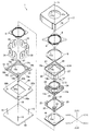
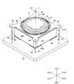
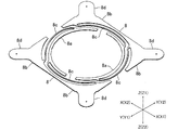
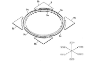
図1は、本発明の実施の形態にかかるレンズ駆動装置1の斜視図である。図2は、図1に示すレンズ駆動装置1の分解斜視図である。図3は、図1に示すレンズ駆動装置1の構成を説明するための平面図である。図4は、図1に示すレンズ駆動装置1の概略構成を側面から説明するための概略図である。図5は、図2に示す第1保持体2および第2保持体3を基板18が支持している状態を示す斜視図である。図6は、図2に示す板バネ8の斜視図である。図7は、図2に示す板バネ9の斜視図である。なお、図3では、図2に示す板バネ8、レンズホルダ12、スペーサ15、カバー部材17および磁石固定部材14の底部14a等を取り外した状態のレンズ駆動装置1の平面図が図示されている。また、図4では、コイル固定部材19および保護部材20等の図示を省略している。
(Schematic configuration of lens driving device)
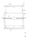
FIG. 1 is a perspective view of a lens driving device 1 according to an embodiment of the present invention. FIG. 2 is an exploded perspective view of the lens driving device 1 shown in FIG. FIG. 3 is a plan view for explaining the configuration of the lens driving device 1 shown in FIG. FIG. 4 is a schematic diagram for explaining a schematic configuration of the lens driving device 1 shown in FIG. 1 from the side. FIG. 5 is a perspective view showing a state in which the
以下の説明では、図1等に示すように、互いに略直交する3方向のそれぞれをX方向、Y方向およびZ方向とする。また、図1等のX1方向側を「右」側、X2方向側を「左」側、Y1方向側を「前」側、Y2方向側を「後(後ろ)」側、Z1方向側を「上」側、Z2方向側を「下」側とする。また、Y方向とZ方向とから形成される平面をYZ平面、Z方向とX方向とから形成される平面をZX平面とする。 In the following description, as shown in FIG. 1 and the like, the three directions substantially orthogonal to each other are defined as an X direction, a Y direction, and a Z direction. Further, in FIG. 1 and the like, the X1 direction side is the “right” side, the X2 direction side is the “left” side, the Y1 direction side is the “front” side, the Y2 direction side is the “rear (rear)” side, and the Z1 direction side is “ The “upper” side and the Z2 direction side are the “lower” side. A plane formed from the Y direction and the Z direction is a YZ plane, and a plane formed from the Z direction and the X direction is a ZX plane.
本形態のレンズ駆動装置1は、携帯電話、ドライブレコーダあるいは監視カメラシステム等で使用される比較的小型のカメラに搭載されるものであり、図1に示すように、全体として略四角柱状に形成されている。具体的には、レンズ駆動装置1は、撮影用のレンズの光軸Lの方向(光軸方向)から見たときの形状が略正方形状となるように形成されている。また、本形態では、レンズ駆動装置1の4つの側面は、YZ平面またはZX平面と略平行になっている。 The lens driving device 1 of this embodiment is mounted on a relatively small camera used in a mobile phone, a drive recorder, a surveillance camera system, or the like, and is formed in a substantially quadrangular prism shape as a whole as shown in FIG. Has been. Specifically, the lens driving device 1 is formed so that the shape of the lens for photographing when viewed from the direction of the optical axis L (optical axis direction) is a substantially square shape. In this embodiment, the four side surfaces of the lens driving device 1 are substantially parallel to the YZ plane or the ZX plane.
レンズ駆動装置1は、図1〜図5に示すように、撮影用のレンズを保持し光軸方向へ移動可能な第1保持体2と、光軸方向へ第1保持体2が移動可能となるように第1保持体2を保持する第2保持体3と、光軸方向に略直交する方向へ第2保持体3が移動可能となるように第2保持体3を保持する固定体4と、光軸方向へ第1保持体2を駆動するための第1駆動機構5と、左右方向へ第2保持体3を駆動するための第2駆動機構6と、前後方向へ第2保持体3を駆動するための第3駆動機構7とを備えている。
As shown in FIGS. 1 to 5, the lens driving device 1 holds a photographing lens and can move in the optical axis direction, and the first holding body 2 can move in the optical axis direction. A
また、レンズ駆動装置1は、第1保持体2と第2保持体3とを繋ぐための板バネ8、9と、第2保持体3と固定体4とを繋ぐための複数本のワイヤ10とを備えている。すなわち、本形態では、第1保持体2は、板バネ8、9によって、光軸方向へ移動可能に第2保持体3に支持され、第2保持体3は、複数本のワイヤ10によって、光軸方向に略直交する方向へ移動可能に固定体4に支持されている。
Further, the lens driving device 1 includes
本形態では、Z方向(上下方向)が光軸方向と一致している。また、本形態では、X方向(左右方向)は、光軸方向に略直交する第1方向であり、Y方向(前後方向)は、光軸方向と第1方向とに略直交する第2方向である。また、本形態では、レンズ駆動装置1の下側(Z2方向側)部分に撮像素子が配置されており、上側(Z1方向側)に配置される被写体が撮影される。すなわち、本形態では、上側は被写体側(物体側)であり、下側は反被写体側(撮像素子側、像側)である。 In this embodiment, the Z direction (vertical direction) coincides with the optical axis direction. In this embodiment, the X direction (left-right direction) is a first direction substantially orthogonal to the optical axis direction, and the Y direction (front-back direction) is a second direction substantially orthogonal to the optical axis direction and the first direction. It is. In this embodiment, the image sensor is disposed on the lower side (Z2 direction side) of the lens driving device 1, and the subject disposed on the upper side (Z1 direction side) is photographed. That is, in this embodiment, the upper side is the subject side (object side), and the lower side is the anti-subject side (imaging element side, image side).
第1保持体2は、撮影用のレンズが固定されたレンズホルダ12を保持するスリーブ13を備えている。第2保持体3は、後述の第1駆動用磁石23、第2駆動用磁石25および第3駆動用磁石27が固定される磁石固定部材14と、磁石固定部材14に固定されるとともに板バネ8の一部が固定されるスペーサ15と、磁石固定部材14に固定されるとともに板バネ9の一部が固定されるスペーサ16とを備えている。固定体4は、レンズ駆動装置1の前後および左右の側面を構成するカバー部材17と、レンズ駆動装置1の下面を構成する基板18と、後述の第2駆動用コイル26および第3駆動用コイル28が固定されるコイル固定部材19と、撮像素子を保護するための保護部材20とを備えている。
The first holding body 2 includes a sleeve 13 that holds a
レンズホルダ12は、たとえば、非磁性の樹脂材料で形成されている。また、レンズホルダ12は、略円筒状に形成されている。このレンズホルダ12の内周側には、撮影用のレンズが固定されている。
The
スリーブ13は、たとえば、非磁性の樹脂材料で形成されている。また、スリーブ13は、略円筒状に形成される筒部13aと、筒部13aの下端側から筒部13aの径方向の外側に向かって広がるように形成される鍔部13bとを備えている。
The sleeve 13 is made of, for example, a nonmagnetic resin material. The sleeve 13 includes a
筒部13aは、その内周側でレンズホルダ12を保持している。すなわち、筒部13aの内周面にレンズホルダ12の外周面が固定されている。鍔部13bは、上下方向から見たときの形状が略正方形状となるように形成されており、上下方向から見たときの第1保持体2の形状は略正方形状となっている。また、上下方向から見たときの鍔部13bの外周端は、左右方向または前後方向と略平行になっている。鍔部13bの上面の四隅には、後述の第1駆動用コイル24が固定されている。また、鍔部13bの四隅には、後述の第1駆動用磁石23が配置される配置孔13cが上下方向に貫通するように形成されている(図3参照)。
The
磁石固定部材14は、磁性材料で形成されている。たとえば、磁石固定部材14は、磁性を有する金属材料で形成されている。また、磁石固定部材14は、底部14aと筒部14bとを有する底付きの略四角筒状に形成されている。具体的には、磁石固定部材14は、上下方向から見たときの形状が略正方形状となる底付きの略四角筒状に形成されており、上下方向から見たときの第2保持体3の形状は略正方形状となっている。上側に配置される底部14aの中心には、上下方向に貫通する貫通孔14cが形成されており、貫通孔14cには、第1保持体2の上端側が配置されている。また、筒部14bを構成する4個の側面は、YZ平面またはZX平面と略平行になっている。磁石固定部材14は、第1保持体2および第1駆動機構5の外周側を囲むように配置されるとともに、カバー部材17の内側に配置されている。
The magnet fixing member 14 is made of a magnetic material. For example, the magnet fixing member 14 is made of a metal material having magnetism. Moreover, the magnet fixing member 14 is formed in the substantially square cylinder shape with the bottom which has the
スペーサ15、16は、たとえば、絶縁性の樹脂材料で形成されている。また、スペーサ15、16は、略正方形状の薄板状に形成されている。上下方向から見たときのスペーサ15、16の外周端は、左右方向または前後方向と略平行になっている。スペーサ15、16の中心には、上下方向に貫通する貫通孔15a、16aが形成されている。貫通孔15aには、第1保持体2の上端側が配置され、貫通孔16aには、第1保持体2の下端側が配置されている。
The
スペーサ15は、磁石固定部材14の底部14aの上面に固定されている。また、スペーサ15の上面には、板バネ8を構成する後述の第2固定部8bが固定されている。スペーサ16は、磁石固定部材14の筒部14bの下端に固定されている。また、スペーサ16の下面には、板バネ9を構成する後述の第2固定部9bが固定されている。
The
カバー部材17は、たとえば、ステンレス鋼板等の非磁性の金属材料で形成されている。また、カバー部材17は、底部17aと筒部17bとを有する底付きの略四角筒状に形成されている。具体的には、カバー部材17は、上下方向から見たときの形状が略正方形状となる底付きの略四角筒状に形成されている。上側に配置される底部17aの中心には、上下方向に貫通する貫通孔17cが形成されている。また、筒部17bを構成する4個の側面は、YZ平面またはZX平面と略平行になっている。カバー部材17は、第1保持体2、第2保持体3、第1駆動機構5、第2駆動機構6および第3駆動機構7の外周側を囲むように配置されている。
The
基板18は、略正方形の板状に形成された回路基板である。この基板18は、主としてエポキシガラス(ガラエポ)等の非磁性材料で形成されている。上下方向から見たときの基板18の外周端は、左右方向または前後方向と略平行になっている。基板18の中心には、図示を省略する撮像素子が実装されている。また、基板18には、レンズ駆動装置1の傾きの変化を検出するためのジャイロスコープ(角速度センサ)等のセンサや、第1駆動機構5、第2駆動機構6および第3駆動機構7を駆動、制御するための駆動回路、制御回路等が実装されている。さらに、基板18には、後述の第1駆動用コイル24、第2駆動用コイル26および第3駆動用コイル28へ電流を供給するための給電用の回路パターンが形成されている。
The
コイル固定部材19は、たとえば、非磁性の樹脂材料で形成されている。また、コイル固定部材19は、略正方形状の板状に形成されており、上下方向から見たときのコイル固定部材19の外周端は、左右方向または前後方向と略平行になっている。コイル固定部材19の中心には、上下方向に貫通する貫通孔19aが形成されている。また、コイル固定部材19の四隅には、ワイヤ10が挿通される挿通孔19bが上下方向に貫通するように形成されている。また、コイル固定部材19の外周端には、後述の第2駆動用コイル26および第3駆動用コイル28の下端側を固定するための凹部19cが左右方向の内側または前後方向の内側に向かって窪むように形成されている。
The
コイル固定部材19の上面には、板バネ8を構成する後述のワイヤ固定部8dが下方向へ変形したときに第2保持体3の下面側に当接する当接部材21が固定されている(図2参照)。本形態では、コイル固定部材19の四隅の近傍のそれぞれに(すなわち、コイル固定部材19の四隅の近傍の4箇所に)当接部材21が固定されている。
On the upper surface of the
当接部材21は、たとえば、非磁性の樹脂材料で形成されている。また、当接部材21は、たとえば、略三角柱状に形成され、コイル固定部材19の上面から上側に向かって突出するようにコイル固定部材19に固定されている。なお、当接部材21は、コイル固定部材19と一体で形成されても良い。すなわち、コイル固定部材19の四隅の近傍の上面に、上側に向かって突出するようにコイル固定部が形成されても良い。
The
保護部材20は、たとえば、非磁性の樹脂材料で形成されている。また、保護部材20は、略正方形状の板状に形成されており、上下方向から見たときの保護部材20の外周端は、左右方向または前後方向と略平行になっている。保護部材20の中心には、上下方向に貫通する貫通孔20aが形成されており、貫通孔20aには、基板18に実装される撮像素子が配置されている。また、保護部材20の四隅には、ワイヤ10が挿通される挿通孔20bが上下方向に貫通するように形成されている。保護部材20は、カバー部材17の下端側に固定されている。また、保護部材20の上面には、コイル固定部材19が固定され、保護部材20の下面には、基板18が固定されている。
The
本形態では、上下方向から見たときに、第1保持体2の中心(機械的な重心)は、光軸Lと略一致し、第2保持体3の中心(機械的な重心)は、光軸Lと略一致し、固定体4の中心(機械的な重心)は、光軸Lと略一致している。すなわち、本形態では、上下方向から見たときに、レンズ駆動装置1の中心(機械的な重心)は、光軸Lと略一致している。
In this embodiment, the center (mechanical center of gravity) of the first holding body 2 substantially coincides with the optical axis L when viewed from the vertical direction, and the center (mechanical center of gravity) of the
板バネ8、9は、弾性材料で形成されている。また、板バネ8、9は、導電性材料で形成されている。たとえば、板バネ8、9は、弾性および導電性を有する金属材料で形成されている。板バネ8、9は、その厚さ方向と上下方向とが略平行になるように配置されている。本形態では、スリーブ13の上端側に2個の板バネ8が配置され、スリーブ13の下端側に1個の板バネ9が配置されている。また、本形態では、上下方向に略直交する方向における板バネ8、9のバネ定数は、上下方向における板バネ8、9のバネ定数よりも大きくなっている。
The
板バネ8は、図6に示すように、スリーブ13の上端側に固定される第1固定部8aと、スペーサ15の上面に固定される2個の第2固定部8bと、第1固定部8aと第2固定部8bとを繋ぐ2個の腕部8cと、ワイヤ10の上端側が固定される2個のワイヤ固定部8dとを備えている。また、板バネ8は、2個の板バネ8をスリーブ13等に取り付けたときの外形が略正方形状となるように形成されている。また、2個の板バネ8によって形成される略正方形の上下方向から見たときの外周端は、左右方向または前後方向と略平行になっている。
As shown in FIG. 6, the
第1固定部8aは、略半円弧状に形成されている。第2固定部8bは、略三角形状に形成されており、2個の板バネ8によって形成される略正方形の四隅に配置されている。すなわち、第1固定部8aは、第2固定部8bよりも径方向の内側に配置されている。腕部8cは、第1保持体2を支持するバネ部として作用する。この腕部8cは、所定のバネ力を得ることができるように略1/4円弧状に形成されている。
The
ワイヤ固定部8dは、第2固定部8bから径方向の外側に向かって突出するように形成されている。具体的には、ワイヤ固定部8dは、第2固定部8bから左右方向および前後方向に対して略45°傾いた方向に向かって突出するように形成されている。すなわち、ワイヤ固定部8dは、第2保持体3の中心(すなわち、光軸L)を略中心にして略90°ピッチで4箇所に配置されている。
The
また、ワイヤ固定部8dは、上下方向から見たときの形状が略半長円形状となるように形成されている。すなわち、上下方向から見たときに、ワイヤ固定部8dは、第2固定部8bから左右方向および前後方向に対して略45°傾いた方向に向かって略一定の幅で突出するとともに、ワイヤ固定部8dの端部は、半円状になっている。ワイヤ固定部8dには、ワイヤ10の上端側が挿通される挿通孔が上下方向に貫通するように形成されている。
Further, the
本形態では、第2固定部8bは、第2保持体3に固定される固定部であり、ワイヤ固定部8dは、光軸方向に弾性変形可能な変形部である。また、本形態では、固定部である第2固定部8bと変形部であるワイヤ固定部8dとによって弾性部材が構成されている。さらに、本形態では、第1固定部8aと第2固定部8bと腕部8cとによって第1保持体2と第2保持体3とを繋ぐ連結用板バネが構成されている。
In this embodiment, the
板バネ9は、図7に示すように、スリーブ13の下端側に固定される第1固定部9aと、スペーサ16の下面に固定される4個の第2固定部9bと、第1固定部9aと第2固定部9bとを繋ぐ4個の腕部9cとを備えている。また、板バネ9は、その外形が略正方形状となるように形成されており、上下方向から見たときの板バネ9の外周端は、左右方向または前後方向と略平行になっている。
As shown in FIG. 7, the
第1固定部9aは、略円形状に形成されている。第2固定部9bは、略三角形状に形成されており、板バネ9の四隅に配置されている。腕部9cは、第1保持体2を支持するバネ部として作用する。この腕部9cは、所定のバネ力を得ることができるように略1/4円弧状に形成されている。
The 1st fixing |
ワイヤ10は、弾性材料で形成されている。また、ワイヤ10は、導電性材料で形成されている。たとえば、ワイヤ10は、弾性および導電性を有する金属材料で形成されている。また、ワイヤ10は、細長い略円柱状に形成されるとともに直線状に形成されている。なお、ワイヤ10は、細長い略四角柱状等の略多角柱状に形成されても良いし、細長い略楕円柱状等に形成されても良い。
The
図5に示すように、ワイヤ10の下端側は、基板18に固定されている。ワイヤ10の上端側は、板バネ8のワイヤ固定部8dに固定されて電気的に接続されている。具体的には、4個のワイヤ固定部8dのそれぞれに、1本のワイヤ10の上端側が固定されており、1個の板バネ8には、2本のワイヤ10の上端側が固定されて電気的に接続されている。また、1個の板バネ8に固定される2本のワイヤ10のうちの一方のワイヤ10の下端側は、基板18に形成される給電用の回路パターンに電気的に接続されている。
As shown in FIG. 5, the lower end side of the
本形態では、図5に示すように、上下方向から見たときの第2保持体3の四隅の近傍のそれぞれに、ワイヤ10が配置されており、第2保持体3は、4本のワイヤ10によって固定体4に支持されている。また、本形態では、4本のワイヤ10は、上下方向から見たときに、第2保持体3の中心を略中心にして(すなわち、光軸Lを略中心して)、90°の回転対称に配置されている。
In this embodiment, as shown in FIG. 5, the
また、本形態では、図4等に示すように、ワイヤ10は、上下方向に略直交する方向から見たときにワイヤ10の上端側がワイヤ10の下端側よりも広がるように上下方向に対して傾斜している。具体的には、ワイヤ10は、ワイヤ10の下端側が上下方向(光軸方向)に略平行な第2保持体3の中心軸(すなわち、光軸L)に向かうように上下方向に対して緩やかに傾斜している。
Further, in this embodiment, as shown in FIG. 4 and the like, the
また、上下方向から見たときに、4本のワイヤ10の上端側は、第2保持体3の中心から略等しい距離でワイヤ固定部8dに固定され、4本のワイヤ10の下端側は、第2保持体3の中心から略等しい距離で基板18に固定されている。さらに、本形態では、上下方向に対するワイヤ10の左右方向から見たときの傾きと、上下方向に対するワイヤ10の前後方向から見たときの傾きとが略等しくなっている。たとえば、上下方向に略直交するとともに左右方向および前後方向に対して略45°傾いた方向から見たときの上下方向に対する傾斜角度θ(図5参照)は、約30°以下となっている。具体的には、傾斜角度θは、約14°となっている。また、本形態では、左右方向から見たときに2本のワイヤ10が重なり、前後方向から見たときに2本のワイヤ10が重なるように、4本のワイヤ10が配置されている。
Further, when viewed from the vertical direction, the upper ends of the four
なお、2個の板バネ8のそれぞれには、後述の第1駆動用コイル24の巻き始め側の端部および巻き終わり側の端部のそれぞれが固定されて電気的に接続されており、板バネ8に固定される2本のワイヤ10のうちの一方のワイヤ10および板バネ8は、第1駆動用コイル24に基板18から電流を供給する給電機能を果たしている。
Each of the two
第1駆動機構5は、略三角柱状に形成される第1駆動用磁石23と、略三角筒状に巻回されて形成される第1駆動用コイル24とを備えている。第2駆動機構6は、略長方形の平板状に形成される第2駆動用磁石25と、略長方形の平板状に巻回されて形成される第2駆動用コイル26とを備えている。第3駆動機構7は、略長方形の平板状に形成される第3駆動用磁石27と、略長方形状の平板状に巻回されて形成される第3駆動用コイル28とを備えている。以下、第1駆動機構5、第2駆動機構6および第3駆動機構7の構成について説明する。
The
(第1駆動機構、第2駆動機構および第3駆動機構の構成)
図8は、図2に示す第1駆動用磁石23および第1駆動用コイル24の側面図である。図9は、図8のE−E方向から第1駆動用磁石片32および第1駆動用コイル24を示す図である。図10は、図3のF−F方向から第2駆動用磁石25と第2駆動用コイル26との対向関係を説明するための図である。
(Configuration of the first drive mechanism, the second drive mechanism, and the third drive mechanism)
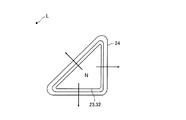
FIG. 8 is a side view of the
第1駆動機構5は、上述のように、第1駆動用磁石23と第1駆動用コイル24とを備えている。
As described above, the
第1駆動用磁石23は、上述のように、略三角柱状に形成されており、その長手方向が上下方向と略平行になるように、磁石固定部材14の筒部14bの内周側に配置されている。第1駆動用コイル24は、上述のように、略三角筒状に形成されており、その内周面が第1駆動用磁石23の外周面と所定の隙間を介して対向するように配置されている。本形態では、図3に示すように、上下方向から見たときの第1保持体2および第2保持体3の四隅のそれぞれに、第1駆動用磁石23および第1駆動用コイル24が配置されている。
As described above, the
第1駆動用磁石23は、図8に示すように、上下方向で重なるように配置される略三角柱状の2個の第1駆動用磁石片31、32と、第1駆動用磁石片31、32の間に配置される略三角形状の磁性板33とを備えている。本形態では、第1駆動用磁石片31が上側に配置され、第1駆動用磁石片32が下側に配置されている。また、第1駆動用磁石片31の下端面と磁性板33の上端面とが固定され、第1駆動用磁石片32の上端面と磁性板33の下端面とが固定されている。
As shown in FIG. 8, the
第1駆動用磁石片31、32は、上下方向から見たときの形状が略直角二等辺三角形となるように形成されており、第1駆動用磁石片31、32は、上下方向から見たときに、その斜辺を除く2辺が磁石固定部材14の筒部14bの内周面と略平行になるように配置されている。磁性板33は、磁性材料で形成されている。この磁性板33は、上下方向から見たときの形状が第1駆動用磁石片31、32と同様の略直角二等辺三角形状となる平板状に形成されている。
The first
第1駆動用磁石片31の上端面は、磁石固定部材14の底部14aの下面に固定されており、第1駆動用磁石片31の上端面は、底部14aの下面に当接している。第1駆動用磁石片32の下端面には、磁性材料によって平板状に形成された磁性部材35が固定されており、第1駆動用磁石片32の下端面は、磁性部材35の上面に当接している。磁性部材35は、4個の第1駆動用磁石片32が固定されるように、略正方形の枠状に形成されている(図2参照)。磁性部材35の下面は、スペーサ16の上面に固定されている。また、上下方向から見たときの磁性部材35の外周端は、左右方向または前後方向と略平行になっており、磁性部材35の外周端は、磁石固定部材14の筒部14bの内周面に当接している。本形態では、磁石固定部材14および磁性部材35が第1駆動用磁石23のヨークとしての機能を果たしている。
The upper end surface of the first driving magnet piece 31 is fixed to the lower surface of the
第1駆動用コイル24は、図3、図9に示すように、上下方向から見たときの形状が略直角二等辺三角形状となるように巻回されている。第1駆動用コイル24は、スリーブ13の鍔部13bの上面の四隅に固定されている。具体的には、第1駆動用コイル24は、第1駆動用コイル24の内周面と第1駆動用磁石23の外周面とが所定の隙間を介して略平行になるように、鍔部13bの上面に固定されており、第1駆動用コイル24は、磁石固定部材14の筒部14bの内側に配置されている。なお、第1駆動用コイル24と筒部14bとの間には所定の隙間が形成されており、第1駆動用コイル24は、第2保持体3に対してスリーブ13と一緒に上下方向へ移動可能となっている。
As shown in FIGS. 3 and 9, the
本形態では、4個の第1駆動用コイル24は、1本の導線が順次巻回されて形成されている。また、第1駆動用コイル24の巻き始め側の端部は、2個の板バネ8の一方の第1固定部8aに固定されて電気的に接続され、第1駆動用コイル24の巻き終わり側の端部は、2個の板バネ8の他方の第1固定部8aに固定されて電気的に接続されている。
In the present embodiment, the four first driving coils 24 are formed by sequentially winding one conductive wire. The end of the
図8に示すように、第1駆動用磁石23を構成する2個の第1駆動用磁石片31、32は、上下方向において、同じ磁極同士(S極とS極、あるいは、N極とN極)が対向するように配置されている。すなわち、第1駆動用磁石片31、32同士の対向面は、いずれも同じ磁極に着磁されている。たとえば、第1駆動用磁石片31、32同士の対向面はいずれもN極に着磁されている。そのため、第1駆動用磁石片31、32の間には、図8、図9の矢印のように、第1駆動用コイル24の全周を通過する磁束が発生している。
As shown in FIG. 8, the two first
第2駆動機構6は、上述のように、第2駆動用磁石25と第2駆動用コイル26とを備えている。
As described above, the
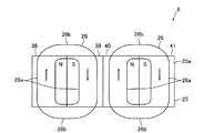
第2駆動用磁石25は、上述のように、略長方形の平板状に形成されており、その厚さ方向が前後方向と略平行になるように、磁石固定部材14の筒部14bの外周側に配置されている。また、第2駆動用磁石25は、その長手方向が左右方向と略平行になり、その短手方向が上下方向と略平行になるように、筒部14bの外周側に配置されている。第2駆動用コイル26は、上述のように、略長方形の平板状に形成されており、その厚さ方向が前後方向と略平行になるように、かつ、前後方向において所定の隙間を介して第2駆動用磁石25と対向するように、前後方向における第2駆動用磁石25の外側に配置されている。
As described above, the
本形態では、前後方向における磁石固定部材14の両側のそれぞれに、1個の第2駆動用磁石25および2個の第2駆動用コイル26が互いに対向するように配置されている。また、光軸方向における第2駆動機構6の駆動力の中心が光軸方向における第2保持体3の中心よりも上側になるように、第2駆動用磁石25および第2駆動用コイル26が対向配置されている。すなわち、光軸方向に略直交する方向から見たときに、第2駆動機構6の駆動力の中心が第2保持体3の中心よりも上側になるように、第2駆動用磁石25および第2駆動用コイル26が対向配置されている。
In the present embodiment, one
第2駆動用磁石25は、磁石固定部材14の筒部14bの前側面と後側面とのそれぞれに固定されており、前後方向における第2駆動用磁石25の内側面は、筒部14bの前側面または後側面に当接している。本形態では、磁石固定部材14が第2駆動用磁石25のヨークとしての機能を果たしている。
The
また、第2駆動用磁石25は、図10等に示すように、4個の第2駆動用磁石片38〜41によって構成されている。第2駆動用磁石片38〜41は、略長方形の薄板状に形成されており、左右方向においてこの順番で互いに当接した状態で固定されている。また、第2駆動用磁石片38〜41は、第2駆動用磁石25の第2駆動用コイル26との対向面25aにN極とS極とが交互に配置されるように着磁されている。
Moreover, the
第2駆動用コイル26は、上述のように略長方形状に巻回されており、互いに略平行な2個の長辺部26aと互いに略平行で長辺部26aよりも短い2個の短辺部26bとから構成される空芯コイルである(図10参照)。この第2駆動用コイル26の下端側は、長辺部26aが上下方向と略平行になるように、コイル固定部材19に固定されている。
The
また、磁石固定部材14の前側面に固定される第2駆動用磁石25と対向するように2個の第2駆動用コイル26が左右方向で隣接配置され、磁石固定部材14の後側面に固定される第2駆動用磁石25と対向するように2個の第2駆動用コイル26が左右方向で隣接配置されている。左右方向で隣接配置される2個の第2駆動用コイル26の巻回方向は同じになっている。また、本形態では、たとえば、磁石固定部材14の前面側に配置される2個の第2駆動用コイル26と磁石固定部材14の後面側に配置される2個の第2駆動用コイル26とは、1本の導線が順次巻回されて形成されている。
Further, two second driving coils 26 are arranged adjacent to each other in the left-right direction so as to face the
本形態では、図10に示すように、第2駆動用磁石25の対向面25aの4つの磁極のそれぞれと、左右方向で並ぶ4個の長辺部26aのそれぞれとが対向するように、第2駆動用磁石25および第2駆動用コイル26が形成され、配置されている。
In the present embodiment, as shown in FIG. 10, the four magnetic poles of the facing
第3駆動機構7は、上述のように、第3駆動用磁石27と第3駆動用コイル28とを備えている。
As described above, the
第3駆動用磁石27は、上述のように、略長方形の平板状に形成されており、その厚さ方向が左右方向と略平行になるように、磁石固定部材14の筒部14bの外周側に配置されている。また、第3駆動用磁石27は、その長手方向が前後方向と略平行になり、その短手方向が上下方向と略平行になるように、筒部14bの外周側に配置されている。第3駆動用コイル28は、上述のように、略長方形の平板状に形成されており、その厚さ方向が左右方向と略平行になるように、かつ、左右方向において所定の隙間を介して第3駆動用磁石27と対向するように、左右方向における第3駆動用磁石27の外側に配置されている。
As described above, the
本形態では、左右方向における磁石固定部材14の両側のそれぞれに、1個の第3駆動用磁石27および2個の第3駆動用コイル28が互いに対向するように配置されている。また、光軸方向における第3駆動機構7の駆動力の中心が光軸方向における第2保持体3の中心よりも上側になるように、第3駆動用磁石27および第3駆動用コイル28が対向配置されている。すなわち、光軸方向に略直交する方向から見たときに、第3駆動機構7の駆動力の中心が第2保持体3の中心よりも上側になるように、第3駆動用磁石27および第3駆動用コイル28が対向配置されている。
In the present embodiment, one
第3駆動用磁石27は、磁石固定部材14の筒部14bの右側面と左側面とのそれぞれに固定されており、左右方向における第3駆動用磁石27の内側面は、筒部14bの右側面または左側面に当接している。本形態では、磁石固定部材14が第3駆動用磁石27のヨークとしての機能を果たしている。
The
また、第3駆動用磁石27は、第2駆動用磁石25と同様に、4個の第2駆動用磁石片38〜41によって構成されている。第3駆動用磁石27では、第2駆動用磁石片38〜41は、前後方向においてこの順番で互いに当接した状態で固定されている。第3駆動用磁石27の第3駆動用コイル28との対向面27aは、第2駆動用磁石25の対向面25aと同様に、N極とS極とが交互に配置されるように4極に着磁されている。
Further, the
第3駆動用コイル28は、第2駆動用コイル26と同形状の空芯コイルであり、互いに略平行な2個の長辺部28aと互いに略平行で長辺部28aよりも短い2個の短辺部とを備えている。この第3駆動用コイル28の下端側は、第2駆動用コイル26と同様に、長辺部28aが上下方向と略平行になるように、コイル固定部材19に固定されている。
The
また、磁石固定部材14の右側面に固定される第3駆動用磁石27と対向するように2個の第3駆動用コイル28が前後方向で隣接配置され、磁石固定部材14の左側面に固定される第3駆動用磁石27と対向するように2個の第3駆動用コイル28が前後方向で隣接配置されている。前後方向で隣接配置される2個の第3駆動用コイル28の巻回方向は同じになっている。また、本形態では、たとえば、磁石固定部材14の右面側に配置される2個の第3駆動用コイル28と磁石固定部材14の左面側に配置される2個の第3駆動用コイル28とは、1本の導線が順次巻回されて形成されている。
Two third driving coils 28 are adjacently arranged in the front-rear direction so as to face the
本形態では、第2駆動用磁石25および第2駆動用コイル26と同様に、第3駆動用磁石27の対向面27aの4つの磁極のそれぞれと、前後方向で並ぶ4個の長辺部28aのそれぞれとが対向するように、第3駆動用磁石27および第3駆動用コイル28が形成され、配置されている。
In this embodiment, similarly to the
(ワイヤ固定部および当接部材の作用)
図11は、図2に示す板バネ8のワイヤ固定部8dおよび当接部材21の作用を説明するための図である。
(Operation of wire fixing part and contact member)
FIG. 11 is a view for explaining the operation of the
上述のように、本形態では、上下方向に対する傾斜角度θが約30°以下となるように、ワイヤ10が配置されている。そのため、ワイヤ10は、上下方向にはほとんど変形しない。また、本形態のワイヤ10の径は非常に小さくなっている。したがって、ワイヤ10に下方向の力がかかるとワイヤ10は座屈しやすい。そこで、本形態では、ワイヤ固定部8dおよび当接部材21によって、ワイヤ10の座屈が防止されている。
As described above, in this embodiment, the
具体的には、第2保持体3等の可動部分に上下方向の力がかかったときに、ワイヤ10の座屈荷重よりも小さな力で、第2固定部8bとワイヤ固定部8dとの境界部を支点にしてワイヤ固定部8dが上下方向に弾性変形するように、ワイヤ固定部8dの幅および厚さが設定されており、第2保持体3等の可動部分に下方向の力がかかったときには、ワイヤ10の座屈荷重よりも小さな力で、ワイヤ固定部8dは上方向に弾性変形する。また、当接部材21は、ワイヤ固定部8dが上方向へ変形したときに、ワイヤ10が座屈する前に第2保持体3の下面側に当接する位置に配置されている。たとえば、当接部材21は、第2保持体3を構成するスペーサ16の下面に固定される板バネ9の第2固定部9bの下面に当接する位置に配置されている。
Specifically, when a vertical force is applied to the movable part such as the
そのため、第2保持体3等の可動部分に下方向の力がかかると、ワイヤ10が座屈する前に、図11に示すように、ワイヤ固定部8dが上方向へ弾性変形する。また、ワイヤ固定部8dが上方向へ弾性変形すると、ワイヤ10が座屈する前に、当接部材21の上面が第2保持体3の下面側に当接して、それ以降の第2保持体3の下方向への動きが規制される。本形態では、このようなワイヤ固定部8dおよび当接部材21の作用によって、ワイヤ10の座屈が防止されている。
Therefore, when a downward force is applied to the movable part such as the
(レンズ駆動装置の概略動作)
以上のように構成されたレンズ駆動装置1では、このレンズ駆動装置1が搭載されるカメラで撮影が行われる際に、第1駆動用コイル24に電流が供給され、第1保持体2が光軸方向に移動して、レンズの焦点調整が行われる。また、基板18に実装されるジャイロスコープによって、カメラの振れが検出されると、このセンサでの検出結果に基づいて、第2駆動用コイル26および/または第3駆動用コイル28に電流が供給され、第2保持体3が第1保持体2とともに左右方向および/または前後方向に移動して、振れが補正される。
(Schematic operation of the lens driving device)
In the lens driving device 1 configured as described above, when shooting is performed with a camera in which the lens driving device 1 is mounted, a current is supplied to the
たとえば、本形態では、ジャイロスコープで検出されたカメラの振れ量に基づいて、第2保持体3を左右方向および/または前後方向へ移動させて振れを補正するために必要となる電流を第2駆動用コイル26や第3駆動用コイル28へ供給するオープン制御によって、第2駆動用コイル26や第3駆動用コイル28への電流の供給量が制御されている。
For example, in this embodiment, based on the camera shake amount detected by the gyroscope, the second current 3 required to correct the shake by moving the
なお、前後方向および左右方向における第2保持体3の位置を検出するためのホール素子等の位置センサをレンズ駆動装置1が備えている場合には、この位置センサの検出結果をモニタしながら、振れを補正するために必要となる電流を第2駆動用コイル26や第3駆動用コイル28へ供給するフィードバック制御(クローズド制御)を行っても良い。
When the lens driving device 1 includes a position sensor such as a Hall element for detecting the position of the
(本形態の主な効果)
以上説明したように、本形態では、撮影用のレンズを保持する第1保持体2は光軸方向へ移動可能となるように第2保持体3に保持され、第2保持体3は前後方向および左右方向(前後左右方向)へ移動可能となるように固定体4に保持されている。そのため、第1駆動機構5によって、第1保持体2とともにレンズを光軸方向へ移動させることができる。すなわち、本形態では、第1駆動機構5を用いて、焦点調整動作を行うことができる。また、第2駆動機構6および第3駆動機構7によって、第1保持体2および第2保持体3とともに前後左右方向へレンズを移動させることができる。したがって、本形態では、前後左右方向へレンズを移動させることで、振れによる撮影像の、光軸方向に略直交する方向でのずれの補正が可能となり、その結果、レンズ駆動装置1が搭載されるカメラで撮影が行われる際の振れを補正することが可能になる。
(Main effects of this form)
As described above, in this embodiment, the first holding body 2 that holds the photographing lens is held by the
本形態では、第1保持体2は、板バネ8、9によって、光軸方向へ移動可能に第2保持体3に支持され、第2保持体3は、ワイヤ10によって、前後左右方向へ移動可能に固定体4に支持されている。そのため、板バネ8、9の弾性力を利用して、光軸方向へ第1保持体2を円滑に移動させ、かつ、所定の基準位置へ第1保持体2を復帰させることが可能になる。また、ワイヤ10の弾性力を利用して、前後左右方向へ第2保持体3を円滑に移動させ、かつ、所定の基準位置へ第2保持体3を復帰させることが可能になる。
In this embodiment, the first holding body 2 is supported by the
また、本形態では、第1保持体2が光軸方向へ移動可能となるように第2保持体3に保持され、第2保持体3が前後左右方向へ移動可能となるように固定体4に保持されているため、第2駆動機構6および/または第3駆動機構7と第1駆動機構5とが同時に作用しても、第1保持体2は第2保持体3に対して光軸方向へのみ相対移動し、第2保持体3は固定体4に対して前後左右方向へのみ相対移動する。したがって、本形態では、振れを補正する際の第1保持体2および第2保持体3の上下方向に対する傾きを抑制することができる。すなわち、本形態では、振れを補正する際のレンズの光軸Lの傾きを抑制することができる。特に本形態では、光軸方向に対する傾斜角度θが約30°以下となるように、ワイヤ10が配置されているため、ワイヤ10は、光軸方向へほとんど変形しない。したがって、第2保持体3が前後左右方向へ移動する際のレンズの光軸Lの傾きを効果的に抑制することができる。すなわち、本形態では、振れを補正する際のレンズの光軸Lの傾きを効果的に抑制することができる。
Further, in this embodiment, the first holding body 2 is held by the
本形態では、第2保持体3等の可動部分に下方向の力がかかったときに、ワイヤ10の座屈荷重よりも小さな力で、ワイヤ固定部8dが上方向に弾性変形する。そのため、落下等の原因でレンズ駆動装置1に光軸方向の衝撃が加わっても、ワイヤ固定部8dを上方向へ弾性変形させて、ワイヤ10の座屈を防止することが可能になる。特に本形態では、ワイヤ固定部8dが上方向へ変形したときに、ワイヤ10が座屈する前に第2保持体3の下面側に当接部材21が当接するため、ワイヤ固定部8dと当接部材21とによって、ワイヤ10の座屈を確実に防止することが可能になる。したがって、本形態では、レンズ駆動装置1の耐衝撃性を高めることが可能になる。
In this embodiment, when a downward force is applied to the movable part such as the
一方で、ワイヤ固定部8dがワイヤ10の座屈荷重よりも小さな力で光軸方向に弾性変形するため、振れを補正する際に第2保持体3が前後左右方向に移動すると、ワイヤ固定部8dが光軸方向に弾性変形して、第2保持体3が傾くおそれがある。しかし、本形態では、光軸方向に略直交する方向から見たときにワイヤ10の上端側がワイヤ10の下端側よりも広がるようにワイヤ10が傾斜している。そのため、ワイヤ10の座屈荷重よりも小さな力でワイヤ固定部8dが光軸方向に弾性変形する場合であっても、振れを補正する際の第2保持体3の傾きを抑制することが可能になる。
On the other hand, since the
すなわち、図12(A)に示すように、光軸方向に略直交する方向から見たときにワイヤ10の上端側がワイヤ10の下端側よりも広がるようにワイヤ10が傾斜している場合には、第2保持体3が前後左右方向に移動してワイヤ固定部8dが光軸方向に弾性変形しても、第2保持体3の傾きを抑制することが可能になる。たとえば、図12(B)に示すように、第2保持体3が図12(B)の左方向へ移動する場合、図12(B)の左側に配置されるワイヤ固定部8dは下方向に弾性変形し、図12(B)の右側に配置されるワイヤ固定部8dは上方向に弾性変形するが、図12(B)の左側に配置されるワイヤ10は左方向へ倒れるように弾性変形し、図12(B)の右側に配置されるワイヤ10は左方向へ立ち上るように弾性変形するため、第2保持体3の傾きを抑制することが可能になる。
That is, as shown in FIG. 12A, when the
一方、図13(A)に示すように、ワイヤ10が光軸方向と略平行に配置されている場合には、第2保持体3が前後左右方向に移動してワイヤ固定部8dが光軸方向に弾性変形すると、第2保持体3は大きく傾きやすくなる。たとえば、図13(B)に示すように、第2保持体3が図13(B)の左方向へ移動する場合、図13(B)の左側に配置されるワイヤ固定部8dは下方向に弾性変形し、図13(B)の右側に配置されるワイヤ固定部8dは上方向に弾性変形するが、図13(B)の左側および右側に配置されるワイヤ10は左方向へ倒れるように弾性変形するため、第2保持体3は大きく傾きやすくなる。
On the other hand, as shown in FIG. 13A, when the
このように本形態では、光軸方向に略直交する方向から見たときにワイヤ10の上端側がワイヤ10の下端側よりも広がるようにワイヤ10が傾斜しているため、振れを補正する際に、ワイヤ固定部8dが光軸方向に弾性変形しても、第2保持体3が傾きにくくなる。したがって、本形態では、レンズ駆動装置1の耐衝撃性を高めつつ、振れを補正する際のレンズの光軸Lの傾きを抑制することが可能になる。
Thus, in this embodiment, the
特に本形態では、ワイヤ固定部8dは、光軸Lを略中心にして略90°ピッチで4箇所に配置され、4本のワイヤ10は、その下端側が光軸Lに向かって傾斜するように配置されている。また、本形態では、光軸方向から見たときに、4本のワイヤ10の上端側は、第2保持体3の中心から略等しい距離でワイヤ固定部8dに固定され、4本のワイヤ10の下端側は、第2保持体3の中心から略等しい距離で基板18に固定されている。さらに、本形態では、光軸方向に対するワイヤ10の左右方向から見たときの傾きと、光軸方向に対するワイヤ10の前後方向から見たときの傾きとが略等しくなっている。また、本形態では、左右方向から見たときに2本のワイヤ10が重なり、前後方向から見たときに2本のワイヤ10が重なるように、4本のワイヤ10が配置されている。
In particular, in this embodiment, the
そのため、本形態では、左右方向および/または前後方向へ第2保持体3が移動する際の第2保持体3の傾きを効果的に抑制することが可能になる。すなわち、本形態では、振れを補正する際のレンズの光軸Lの傾きを効果的に抑制することが可能になる。
Therefore, in this embodiment, it is possible to effectively suppress the inclination of the
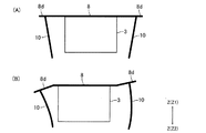
また、本形態では、光軸方向における第2駆動機構6の駆動力の中心および第3駆動機構7の駆動力の中心が光軸方向における第2保持体3の中心よりも上側にある。そのため、光軸方向における第2駆動機構6の駆動力の中心および第3駆動機構7の駆動力の中心が光軸方向における第2保持体3の中心よりも下側にある場合と比較して、振れを補正する際の第2保持体3の傾きを効果的に抑制することができる。
In this embodiment, the center of the driving force of the
すなわち、図14(B)に示すように、光軸方向における第2駆動機構6、第3駆動機構7の駆動力の中心C1が光軸方向における第2保持体3の中心C2よりも下側にある場合には、第2駆動機構6、第3駆動機構7の駆動力の中心C1と板バネ8との距離が長くなるため、前後左右方向へ第2保持体3が移動する際の第2保持体3の傾きが大きくなる。一方、図14(A)に示すように、光軸方向における第2駆動機構6、第3駆動機構7の駆動力の中心C1が光軸方向における第2保持体3の中心C2よりも上側にある場合には、第2駆動機構6、第3駆動機構7の駆動力の中心C1と板バネ8との距離が短くなるため、前後左右方向へ第2保持体3が移動する際の第2保持体3の傾きを抑制することができる。
That is, as shown in FIG. 14B, the center C1 of the driving force of the
本形態では、第2保持体3は、光軸方向から見たときの第2保持体3の四隅の近傍のそれぞれに配置される4本のワイヤ10によって固定体4に支持されている。そのため、最小本数のワイヤ10によって、第2保持体3をバランス良く支持することが可能になる。したがって、レンズ駆動装置1の構成を簡素化しつつ、振れを補正する際の第2保持体3の傾きを効果的に抑制することが可能になる。
In the present embodiment, the
本形態では、板バネ8を構成するワイヤ固定部8dがワイヤ10の座屈を防止する機能を果たしている。そのため、本形態では、第1保持体2を支持する機能を有する部材と、ワイヤ10の座屈を防止する機能を有する部材とが個別に設けられている場合と比較して、レンズ駆動装置1の構成を簡素化することが可能になり、また、レンズ駆動装置1を組み立てる際の部品の取り扱いが容易になる。
In this embodiment, the
本形態では、当接部材21は、コイル固定部材19の上面に固定されている。そのため、当接部材21が第2保持体3の下端側に固定されている場合と比較して、レンズ駆動装置1の可動部分を軽量化することが可能になる。したがって、振れを補正する際のレンズの応答性を高めることが可能になる。
In this embodiment, the
(ワイヤの傾斜角度と光軸の傾きとの関係)
図15は、図1に示すレンズ駆動装置1におけるワイヤ10の傾斜角度θと第2保持体3が光軸方向に略直交する方向へ移動したときの光軸Lの傾きとの関係のシミュレーション結果を示すグラフである。
(Relationship between wire tilt angle and optical axis tilt)
FIG. 15 is a simulation result of the relationship between the inclination angle θ of the
レンズ駆動装置1におけるワイヤ10の傾斜角度θと、第2保持体3が光軸方向に略直交する方向へ移動したときの光軸Lの傾きとの関係のシミュレーションを行った。まず、シミュレーションでは、ワイヤ10の直径、ワイヤ10の長さおよびワイヤ固定部8dの厚さを以下のように設定した。
ワイヤ10の直径:0.070mm
ワイヤ10の長さ:2.75mm
ワイヤ固定部8dの厚さ:0.050mm
また、シミュレーションでは、ワイヤ固定部8dのバネ定数が80(gf/mm)となるように、板バネ8の形状を設定した。
A simulation of the relationship between the inclination angle θ of the
Diameter of wire 10: 0.070 mm
The length of the wire 10: 2.75 mm
In the simulation, the shape of the
以上の条件の下で、傾斜角度θ(図5参照)を変化させながら、第2保持体3を光軸方向に略直交する方向へ0.12mm移動させたときの光軸Lの傾き(すなわち、第2保持体3の傾き)を算出した。
Under the above conditions, the inclination of the optical axis L when the
図15に示すように、シミュレーションの結果、ワイヤ10の傾斜角度θが約14°であると、第2保持体3を光軸方向に略直交する方向へ0.12mm移動させたときの光軸Lの傾きがほぼなくなった。また、ワイヤ10の傾斜角度θが約6°〜約22°の範囲であると、第2保持体3を光軸方向に略直交する方向へ0.12mm移動させたときの光軸Lの傾きが10分以内となった。すなわち、ワイヤ10の傾斜角度θが14±8°の範囲であると、第2保持体3を光軸方向に略直交する方向へ0.12mm移動させたときの光軸Lの傾きを±10分以内に抑えることができた。
As shown in FIG. 15, when the inclination angle θ of the
(他の実施の形態)
上述した形態は、本発明の好適な形態の一例ではあるが、これに限定されるものではなく本発明の要旨を変更しない範囲において種々変形実施が可能である。
(Other embodiments)
The above-described embodiment is an example of a preferred embodiment of the present invention, but is not limited to this, and various modifications can be made without departing from the scope of the present invention.
上述した形態では、ワイヤ固定部8dにワイヤ10の上端側が固定され、基板18にワイヤ10の下端側が固定されている。この他にもたとえば、基板18等の固定体4に固定される固定部および光軸方向に弾性変形可能な変形部を有する弾性部材をレンズ駆動装置1が備えるとともに、ワイヤ10の下端側がこの弾性部材の変形部に固定され、ワイヤ10の上端側が第2保持体3に固定されても良い。この場合には、たとえば、弾性部材は、第2固定部8bおよびワイヤ固定部8dによって構成される板バネとほぼ同様に形成される板バネであり、この弾性部材によって、基板18とワイヤ10の下端側とが繋がれる。また、この場合には、たとえば、ワイヤ10の上端側は、第2保持体3に直接固定される。また、この場合には、光軸方向に略直交する方向から見たときにワイヤ10の下端側がワイヤ10の上端側よりも広がるようにワイヤ10が光軸方向に対して傾斜している。この場合であっても、上述した形態と同様の効果を得ることができる。なお、この場合に、ワイヤ10の上端側が、上述した形態と同様に、ワイヤ固定部8dに固定されても良い。
In the embodiment described above, the upper end side of the
上述した形態では、板バネ8の第2固定部8bが第2保持体3に固定される固定部となっており、また、板バネ8のワイヤ固定部8dがワイヤ10の座屈荷重よりも小さな力で光軸方向へ弾性変形する変形部となっている。この他にもたとえば、第2保持体3に固定される固定部とワイヤ10の座屈荷重よりも小さな力で光軸方向へ弾性変形する変形部とを有する板バネが板バネ8と別体で形成されても良い。また、ゴムやスポンジ等の弾性材料によって、第2保持体3に固定される固定部とワイヤ10の座屈荷重よりも小さな力で光軸方向へ弾性変形する変形部とを有する弾性部材が形成されても良い。
In the embodiment described above, the
上述した形態では、ワイヤ10の上端側が板バネ8に固定され、ワイヤ10の下端側が基板18に固定されている。この他にもたとえば、板バネ9にワイヤ10の下端側が固定され、カバー部材17の底部17aに固定される樹脂製の部材等にワイヤ10の上端側が固定されても良い。この場合には、たとえば、板バネ8のワイヤ固定部8dと同様のワイヤ固定部が板バネ9に形成され、このワイヤ固定部にワイヤ10の下端側が固定される。また、この場合には、たとえば、カバー部材17の底部17aに固定される樹脂製の部材等に、第2保持体3に当接してワイヤ10の座屈を防止する当接部材が固定される。また、この場合には、光軸方向に略直交する方向から見たときにワイヤ10の下端側がワイヤ10の上端側よりも広がるようにワイヤ10が光軸方向に対して傾斜している。
In the embodiment described above, the upper end side of the
上述した形態では、光軸方向における第2駆動機構6の駆動力の中心および第3駆動機構7の駆動力の中心が光軸方向における第2保持体3の中心よりも上側にある。この他にもたとえば、光軸方向における第2駆動機構6の駆動力の中心および/または第3駆動機構7の駆動力の中心と光軸方向における第2保持体3の中心とが光軸方向において略一致しても良い。また、光軸方向における第2駆動機構6の駆動力の中心および第3駆動機構7の駆動力の中心が光軸方向における第2保持体3の中心よりも下側にあっても良い。
In the embodiment described above, the center of the driving force of the
上述した形態では、第1駆動用磁石23と第2駆動用磁石25と第3駆動用磁石27とは、第2保持体3を構成する磁石固定部材14に固定されている。この他にもたとえば、第1駆動用磁石23と第2駆動用磁石25と第3駆動用磁石27とは、固定体4に固定されても良い。この場合には、第1駆動用コイル24は、第1保持体2に固定される。また、この場合には、第2駆動用コイル26および第3駆動用コイル28は、第1保持体2に固定されても良いし、第2保持体3に固定されても良い。また、第1駆動用磁石23と第2駆動用磁石25と第3駆動用磁石27とは、第1保持体2に固定されても良い。この場合には、第2駆動用コイル26および第3駆動用コイル28は、固定体4に固定される。また、この場合には、第1駆動用コイル24は、第2保持体3に固定されても良いし、固定体4に固定されても良い。
In the embodiment described above, the
なお、第1駆動用磁石23が磁石固定部材14に固定されるとともに、第2駆動用磁石25と第3駆動用磁石27とが固定体4または第1保持体2に固定されても良い。また、第1駆動用磁石23が固定体4に固定されるとともに、第2駆動用磁石25と第3駆動用磁石27とが磁石固定部材14または第1保持体2に固定されても良い。また、第1駆動用磁石23が第1保持体2に固定されるとともに、第2駆動用磁石25と第3駆動用磁石27とが磁石固定部材14または固定体4に固定されても良い。
The
上述した形態では、第2保持体3は、4本のワイヤ10によって固定体4に支持されている。この他にもたとえば、第2保持体3は、5本以上のワイヤ10によって固定体4に支持されても良い。この場合には、振れ補正時の光軸Lの傾きを適切に抑制するため、複数本のワイヤ10のそれぞれは、上下方向から見たときの第2保持体3の四隅の近傍のいずれかに配置されることが好ましい。また、複数本のワイヤ10のそれぞれが上下方向から見たときの第2保持体3の四隅の近傍のいずれかに配置される場合には、4個のワイヤ固定部8dのうちの少なくとも1個のワイヤ固定部8dに、2本以上のワイヤ10の上端側が固定される。
In the embodiment described above, the
上述した形態では、第1駆動用磁石23は、略三角柱状に形成されているが、第1駆動用磁石23は、略三角柱状以外の略多角柱状に形成されても良いし、略円柱状や略楕円柱状に形成されても良い。また、上述した形態では、第1駆動用コイル24は、略三角筒状に巻回されて形成されているが、第1駆動用コイル24は、略三角筒状以外の略多角筒状に巻回されても良いし、略円筒状や略楕円筒状に巻回されても良い。
In the embodiment described above, the
上述した形態では、第1駆動機構5は、略三角柱状に形成された第1駆動用磁石23、および、その内周面が第1駆動用磁石23の外周面と所定の隙間を介して対向するように配置された第1駆動用コイル24等によって構成されている。この他にもたとえば、略平面状に巻回された駆動用コイル、および、この駆動用コイルに対向するように配置される駆動用磁石等によって第1駆動機構が構成されても良い。また、コイルが巻回された鉄芯と永久磁石とを備える電磁石によって、第1駆動機構が構成されても良い。また、第2駆動機構6および/または第3駆動機構7は、コイルが巻回された鉄芯と永久磁石とを備える電磁石によって構成されても良いし、第1駆動機構5と同様に、略柱状に形成される第2駆動用磁石、第3駆動用磁石と、略筒状に巻回されて形成される第2駆動用コイル、第3駆動用コイルとによって構成されても良い。
In the embodiment described above, the
上述した形態では、第2駆動用磁石25と第2駆動用コイル26とは、その厚さ方向が前後方向と略平行になるように、かつ、前後方向において対向するように配置されている。この他にもたとえば、第2駆動用磁石25と第2駆動用コイル26とは、その厚さ方向が光軸方向と略平行になるように、かつ、光軸方向において対向するように配置されても良い。同様に、第3駆動用磁石27と第3駆動用コイル28とは、その厚さ方向が光軸方向と略平行になるように、かつ、光軸方向において対向するように配置されても良い。
In the embodiment described above, the
上述した形態では、レンズ駆動装置1は、光軸方向から見たときの形状が略正方形状となるように形成されている。この他にもたとえば、レンズ駆動装置1は、光軸方向から見たときの形状が略長方形状となるように形成されても良いし、その他の略四角形状となるように形成されても良い。また、レンズ駆動装置1は、光軸方向から見たときの形状が略四角形状以外の略多角形状となるように形成されても良いし、光軸方向から見たときの形状が略円形状あるいは略楕円形状となるように形成されても良い。 In the embodiment described above, the lens driving device 1 is formed so that the shape when viewed from the optical axis direction is substantially square. In addition to this, for example, the lens driving device 1 may be formed so as to have a substantially rectangular shape when viewed from the optical axis direction, or may be formed so as to have another substantially rectangular shape. . Further, the lens driving device 1 may be formed so that the shape when viewed from the optical axis direction is a substantially polygonal shape other than the substantially square shape, or the shape when viewed from the optical axis direction is a substantially circular shape. Or you may form so that it may become a substantially ellipse shape.
上述した形態では、光軸方向から見たときのレンズ駆動装置1の4つの側面は、左右方向または前後方向と略平行であり、第2駆動機構6は、左右方向へ第2保持体3を駆動し、第3駆動機構7は、前後方向へ第2保持体3を駆動する。この他にもたとえば、第2駆動機構6が、光軸方向に略直交するとともに左右方向に対して傾いた所定方向へ第2保持体3を駆動し、第3駆動機構7が、この所定方向と光軸方向とに略直交する方向へ第2保持体3を駆動しても良い。たとえば、第2駆動機構6が、光軸方向に略直交するとともに左右方向に対して+45°傾いた方向へ第2保持体3を駆動し、第3駆動機構7が、光軸方向に略直交するとともに左右方向に対して−45°傾いた方向へ第2保持体3を駆動しても良い。
In the embodiment described above, the four side surfaces of the lens driving device 1 when viewed from the optical axis direction are substantially parallel to the left-right direction or the front-rear direction, and the
上述した形態では、上下方向から見たときに、第1保持体2の中心、第2保持体3の中心および固定体4の中心は、光軸Lと略一致している。この他にもたとえば、上下方向から見たときに、第1保持体2の中心、第2保持体3の中心および/または固定体4の中心が光軸Lからずれていても良い。
In the embodiment described above, the center of the first holding body 2, the center of the
1 レンズ駆動装置
2 第1保持体
3 第2保持体
4 固定体
5 第1駆動機構
6 第2駆動機構
7 第3駆動機構
8 板バネ
8a 第1固定部(連結用板バネの一部)
8b 第2固定部(固定部、弾性部材の一部、連結用板バネの一部)
8c 腕部(連結用板バネの一部)
8d ワイヤ固定部(変形部、弾性部材の一部)
10 ワイヤ
21 当接部材
C1 光軸方向における第2駆動機構、第3駆動機構の駆動力の中心
C2 光軸方向における第2保持体の中心
L 光軸(第2保持体の中心軸)
X 第1方向
Y 第2方向
Z 光軸方向
DESCRIPTION OF SYMBOLS 1 Lens drive device 2
8b Second fixing part (fixing part, part of elastic member, part of connecting leaf spring)
8c Arm part (part of connecting leaf spring)
8d Wire fixing part (deformation part, part of elastic member)
10
X 1st direction Y 2nd direction Z Optical axis direction
Claims (11)
前記第2保持体は、複数本の前記ワイヤによって前記光軸方向に略直交する方向へ移動可能に前記固定体に支持され、
複数本の前記ワイヤは、前記光軸方向に略直交する方向から見たときに前記ワイヤの一端側が前記ワイヤの他端側よりも広がるように前記光軸方向に対して傾斜し、
前記変形部は、前記ワイヤの座屈荷重よりも小さな力で前記光軸方向に弾性変形することを特徴とするレンズ駆動装置。 A first holding body that holds the lens and is movable in the optical axis direction of the lens; and a second holding body that holds the first holding body so that the first holding body is movable in the optical axis direction. A fixed body for holding the second holding body so that the second holding body can move in a direction substantially perpendicular to the optical axis direction, and driving the first holding body in the optical axis direction. A first drive mechanism, a second drive mechanism for driving the second holding body in a predetermined first direction substantially orthogonal to the optical axis direction, and substantially orthogonal to the optical axis direction and the first direction. A third drive mechanism for driving the second holding body in a second direction, an elastic member having a fixed portion fixed to the second holding body and a deformable portion elastically deformable in the optical axis direction; A plurality of substantially straight lines in which one end side is fixed to the deformable portion and the other end side is fixed to the fixed body. And a wire,
The second holding body is supported by the fixed body so as to be movable in a direction substantially orthogonal to the optical axis direction by the plurality of wires.
The plurality of wires are inclined with respect to the optical axis direction so that one end side of the wire is wider than the other end side of the wire when viewed from a direction substantially orthogonal to the optical axis direction,
The lens driving device according to claim 1, wherein the deforming portion elastically deforms in the optical axis direction with a force smaller than a buckling load of the wire.
複数本の前記ワイヤは、前記ワイヤの他端側が前記光軸方向に略平行な前記第2保持体の中心軸に向かうように前記光軸方向に対して傾斜していることを特徴とする請求項1記載のレンズ駆動装置。 The deforming portions are arranged at four positions at a pitch of about 90 ° with the center of the second holding body as a substantial center when viewed from the optical axis direction,
The plurality of wires are inclined with respect to the optical axis direction so that the other end side of the wires is directed to a central axis of the second holding body substantially parallel to the optical axis direction. Item 2. The lens driving device according to Item 1.
前記変形部のそれぞれに、1本の前記ワイヤが固定されていることを特徴とする請求項2から4のいずれかに記載のレンズ駆動装置。 Comprising four said wires,
The lens driving device according to claim 2, wherein one of the wires is fixed to each of the deforming portions.
前記板バネと前記連結用板バネとが一体で形成されていることを特徴とする請求項7記載のレンズ駆動装置。 A connecting leaf spring connecting the first holding body and the second holding body;
8. The lens driving device according to claim 7, wherein the plate spring and the connecting plate spring are integrally formed.
前記光軸方向における前記第2駆動機構の駆動力の中心および前記第3駆動機構の駆動力の中心は、前記光軸方向における前記第2保持体の中心よりも前記光軸方向における前記第2保持体の一端側にあることを特徴とする請求項1から8のいずれかに記載のレンズ駆動装置。 The elastic member is disposed on one end side of the second holding body in the optical axis direction,
The center of the driving force of the second driving mechanism and the center of the driving force of the third driving mechanism in the optical axis direction are the second in the optical axis direction than the center of the second holding body in the optical axis direction. The lens driving device according to claim 1, wherein the lens driving device is located on one end side of the holding body.
前記当接部材は、前記固定体に形成または固定されていることを特徴とする請求項1から9のいずれかに記載のレンズ駆動装置。 A contact member that contacts the second holding body to prevent buckling of the wire when the deforming portion is elastically deformed in the optical axis direction;
The lens driving device according to claim 1, wherein the contact member is formed or fixed to the fixed body.
前記第2保持体は、複数本の前記ワイヤによって前記光軸方向に略直交する方向へ移動可能に前記固定体に支持され、
複数本の前記ワイヤは、前記光軸方向に略直交する方向から見たときに前記ワイヤの一端側が前記ワイヤの他端側よりも広がるように前記光軸方向に対して傾斜し、
前記変形部は、前記ワイヤの座屈荷重よりも小さな力で前記光軸方向に弾性変形することを特徴とするレンズ駆動装置。 A first holding body that holds the lens and is movable in the optical axis direction of the lens; and a second holding body that holds the first holding body so that the first holding body is movable in the optical axis direction. A fixed body for holding the second holding body so that the second holding body can move in a direction substantially perpendicular to the optical axis direction, and driving the first holding body in the optical axis direction. A first drive mechanism, a second drive mechanism for driving the second holding body in a predetermined first direction substantially orthogonal to the optical axis direction, and substantially orthogonal to the optical axis direction and the first direction. A third drive mechanism for driving the second holding body in the second direction; an elastic member having a fixed portion fixed to the fixed body; and a deformable portion elastically deformable in the optical axis direction; and the deformable portion A plurality of substantially straight lines having one end fixed to the second holding body and the other end fixed to the second holding body And a wire,
The second holding body is supported by the fixed body so as to be movable in a direction substantially orthogonal to the optical axis direction by the plurality of wires.
The plurality of wires are inclined with respect to the optical axis direction so that one end side of the wire is wider than the other end side of the wire when viewed from a direction substantially orthogonal to the optical axis direction,
The lens driving device according to claim 1, wherein the deforming portion elastically deforms in the optical axis direction with a force smaller than a buckling load of the wire.
Priority Applications (3)
| Application Number | Priority Date | Filing Date | Title |
|---|---|---|---|
| JP2009293732A JP5461981B2 (en) | 2009-12-25 | 2009-12-25 | Lens drive device |
| US13/518,134 US9459464B2 (en) | 2009-12-25 | 2010-12-16 | Lens drive device |
| PCT/JP2010/072607 WO2011078040A1 (en) | 2009-12-25 | 2010-12-16 | Lens drive device |
Applications Claiming Priority (1)
| Application Number | Priority Date | Filing Date | Title |
|---|---|---|---|
| JP2009293732A JP5461981B2 (en) | 2009-12-25 | 2009-12-25 | Lens drive device |
Publications (2)
| Publication Number | Publication Date |
|---|---|
| JP2011133702A JP2011133702A (en) | 2011-07-07 |
| JP5461981B2 true JP5461981B2 (en) | 2014-04-02 |
Family
ID=44195570
Family Applications (1)
| Application Number | Title | Priority Date | Filing Date |
|---|---|---|---|
| JP2009293732A Active JP5461981B2 (en) | 2009-12-25 | 2009-12-25 | Lens drive device |
Country Status (3)
| Country | Link |
|---|---|
| US (1) | US9459464B2 (en) |
| JP (1) | JP5461981B2 (en) |
| WO (1) | WO2011078040A1 (en) |
Families Citing this family (37)
| Publication number | Priority date | Publication date | Assignee | Title |
|---|---|---|---|---|
| JP5762904B2 (en) * | 2011-09-20 | 2015-08-12 | 日本電産サンキョー株式会社 | Lens drive device |
| US8817116B2 (en) * | 2011-10-28 | 2014-08-26 | Lg Innotek Co., Ltd. | Camera module |
| US8698952B2 (en) | 2011-10-31 | 2014-04-15 | Lg Innotek Co., Ltd. | Camera module |
| US9300196B2 (en) * | 2011-11-16 | 2016-03-29 | Lg Innotek Co., Ltd. | Voice coil motor |
| KR101946797B1 (en) * | 2011-12-23 | 2019-04-25 | 엘지이노텍 주식회사 | Voice coil motor |
| KR101950020B1 (en) * | 2011-12-23 | 2019-02-19 | 엘지이노텍 주식회사 | Voice coil motor |
| KR101931183B1 (en) | 2011-12-23 | 2018-12-21 | 엘지이노텍 주식회사 | Voice coil motor |
| KR101878907B1 (en) * | 2011-11-16 | 2018-07-17 | 엘지이노텍 주식회사 | Voice coil motor |
| JP5409756B2 (en) * | 2011-12-07 | 2014-02-05 | 台湾東電化股▲ふん▼有限公司 | Elastic support structure of optical vibration isolator and optical vibration isolator using the same |
| JP2013125080A (en) * | 2011-12-13 | 2013-06-24 | Micro Uintekku Kk | Swing device support mechanism of photographing optical device |
| JP5512857B2 (en) * | 2012-06-18 | 2014-06-04 | シャープ株式会社 | CAMERA MODULE, ELECTRONIC DEVICE MOUNTING THE CAMERA MODULE, AND METHOD FOR PRODUCING THE CAMERA MODULE |
| US10423003B2 (en) | 2012-11-29 | 2019-09-24 | Nidec Sankyo Corporation | Photographing optical device |
| KR20150097766A (en) | 2012-12-20 | 2015-08-26 | 애플 인크. | Voice coil motor optical image stabilization |
| JP2016508700A (en) * | 2013-02-14 | 2016-03-22 | レッド.コム,インコーポレイテッド | Video camera |
| TWI594057B (en) * | 2013-05-06 | 2017-08-01 | 台灣東電化股份有限公司 | Electromagnetic lens driving device |
| CN104238069A (en) * | 2013-06-17 | 2014-12-24 | 台湾东电化股份有限公司 | Lens driving device with 3D elastic support structure |
| KR102166329B1 (en) * | 2013-08-19 | 2020-10-15 | 삼성전자주식회사 | Camera module |
| KR101504024B1 (en) * | 2013-08-27 | 2015-03-18 | 삼성전기주식회사 | Lens driving device and camera module including the same |
| US9531953B2 (en) | 2013-10-11 | 2016-12-27 | Samsung Electro-Mechanics Co., Ltd. | Camera module and portable electronic device including the same |
| JP5992118B2 (en) * | 2014-02-12 | 2016-09-14 | 富士フイルム株式会社 | Imaging module and electronic device |
| US9618770B2 (en) | 2014-04-11 | 2017-04-11 | Samsung Electro-Mechanics Co., Ltd. | Camera module with function of auto-focus and image stabilize |
| JP6271720B2 (en) * | 2014-05-23 | 2018-01-31 | シャープ株式会社 | Camera module and camera module manufacturing method |
| JP2016051078A (en) | 2014-08-29 | 2016-04-11 | 日本電産コパル株式会社 | Lens drive device |
| KR20160072715A (en) * | 2014-12-15 | 2016-06-23 | 삼성전기주식회사 | Camera module |
| JP6648984B2 (en) * | 2014-12-26 | 2020-02-19 | 日本電産サンキョー株式会社 | Actuator |
| JP2016218334A (en) * | 2015-05-25 | 2016-12-22 | 日本航空電子工業株式会社 | Camera actuator |
| JP2016001312A (en) * | 2015-07-10 | 2016-01-07 | 日本電産コパル株式会社 | Image blur correction device and lens drive device |
| JP6264353B2 (en) * | 2015-10-05 | 2018-01-24 | ミツミ電機株式会社 | Lens drive device |
| CN107092066B (en) * | 2016-02-17 | 2019-08-27 | 日本电产三协株式会社 | Optical unit with shake correcting function |
| JP6944288B2 (en) * | 2017-06-30 | 2021-10-06 | 日本電産サンキョー株式会社 | Actuator |
| US11019336B2 (en) | 2017-07-05 | 2021-05-25 | Red.Com, Llc | Video image data processing in electronic devices |
| US10969652B2 (en) * | 2018-01-10 | 2021-04-06 | Apple Inc. | Camera with folded optics having moveable lens |
| KR20250028506A (en) | 2018-01-26 | 2025-02-28 | 애플 인크. | Folded camera with actuator for moving optics |
| US11061213B2 (en) | 2018-02-07 | 2021-07-13 | Apple Inc. | Folded camera |
| US11314147B1 (en) | 2018-05-31 | 2022-04-26 | Apple Inc. | Folded camera with actuator for moving optics |
| CN114384662B (en) * | 2021-12-28 | 2025-02-07 | 中山联合光电研究院有限公司 | Tilt angle adjustment structure, lens assembly and photographic equipment |
| US20240297562A1 (en) * | 2023-03-02 | 2024-09-05 | Tdk Taiwan Corp. | Optical module |
Family Cites Families (7)
| Publication number | Priority date | Publication date | Assignee | Title |
|---|---|---|---|---|
| JP4495705B2 (en) | 2006-08-31 | 2010-07-07 | 日本電産サンキョー株式会社 | Lens drive device |
| JP4908848B2 (en) * | 2006-01-10 | 2012-04-04 | キヤノン株式会社 | Optical member driving device and imaging device |
| TWM322690U (en) * | 2007-05-11 | 2007-11-21 | Topray Technologies Inc | Focus-driving device capable of resisting impact |
| JP2009009027A (en) * | 2007-06-29 | 2009-01-15 | Canon Inc | Image blur correction device, lens barrel, and imaging device |
| WO2009133691A1 (en) * | 2008-04-30 | 2009-11-05 | 日本電産サンキョー株式会社 | Optical unit with vibration correction function |
| CN102016708B (en) * | 2008-04-30 | 2013-07-31 | 日本电产三协株式会社 | Optical unit having deflection correcting function |
| JP5846346B2 (en) * | 2009-08-21 | 2016-01-20 | ミツミ電機株式会社 | Camera shake correction device |
-
2009
- 2009-12-25 JP JP2009293732A patent/JP5461981B2/en active Active
-
2010
- 2010-12-16 US US13/518,134 patent/US9459464B2/en active Active
- 2010-12-16 WO PCT/JP2010/072607 patent/WO2011078040A1/en not_active Ceased
Also Published As
| Publication number | Publication date |
|---|---|
| US9459464B2 (en) | 2016-10-04 |
| US20130201559A1 (en) | 2013-08-08 |
| JP2011133702A (en) | 2011-07-07 |
| WO2011078040A1 (en) | 2011-06-30 |
Similar Documents
| Publication | Publication Date | Title |
|---|---|---|
| JP5461981B2 (en) | Lens drive device | |
| JP5417136B2 (en) | Lens drive device | |
| JP5417127B2 (en) | Lens drive device | |
| WO2011062123A1 (en) | Lens drive device | |
| JP5620672B2 (en) | Lens drive device | |
| JP5438472B2 (en) | Lens drive device | |
| JP5538020B2 (en) | Optical device for photography | |
| CN102650723B (en) | Lens driving device, auto-focusing camera, and mobile terminal device with camera | |
| CN103901701B (en) | Lens driver, camera module, and portable terminal with camera | |
| US20130121672A1 (en) | Tilt-correction unit | |
| JP2011170214A (en) | Lens driving device | |
| KR20150042681A (en) | Camera module and portable electronic device including the same | |
| JP5604068B2 (en) | Optical unit and manufacturing method thereof | |
| US10168545B2 (en) | Optical image stabilizer with improved magnetic disposition | |
| JP5638845B2 (en) | Method for manufacturing photographing optical device and method for manufacturing lens driving device | |
| JP6461071B2 (en) | Twin lens module | |
| US11215900B2 (en) | Shake correction device, optical unit with shake correction function, and method of manufacturing same | |
| JP5449988B2 (en) | Lens drive device | |
| KR20110007839A (en) | Image Stabilizer | |
| JP6009955B2 (en) | Lens drive device | |
| JP5192998B2 (en) | Blur correction device, lens barrel and optical device | |
| JP5781883B2 (en) | Lens drive device | |
| JP6133092B2 (en) | Optical device for photography | |
| JP2011053600A (en) | Lens driving device | |
| JP2015114644A (en) | Optical device for photography |
Legal Events
| Date | Code | Title | Description |
|---|---|---|---|
| A621 | Written request for application examination |
Free format text: JAPANESE INTERMEDIATE CODE: A621 Effective date: 20121105 |
|
| TRDD | Decision of grant or rejection written | ||
| A01 | Written decision to grant a patent or to grant a registration (utility model) |
Free format text: JAPANESE INTERMEDIATE CODE: A01 Effective date: 20140110 |
|
| A61 | First payment of annual fees (during grant procedure) |
Free format text: JAPANESE INTERMEDIATE CODE: A61 Effective date: 20140116 |
|
| R150 | Certificate of patent or registration of utility model |
Ref document number: 5461981 Country of ref document: JP Free format text: JAPANESE INTERMEDIATE CODE: R150 Free format text: JAPANESE INTERMEDIATE CODE: R150 |
|
| S111 | Request for change of ownership or part of ownership |
Free format text: JAPANESE INTERMEDIATE CODE: R313113 |
|
| R350 | Written notification of registration of transfer |
Free format text: JAPANESE INTERMEDIATE CODE: R350 |
|
| S533 | Written request for registration of change of name |
Free format text: JAPANESE INTERMEDIATE CODE: R313533 |
|
| R350 | Written notification of registration of transfer |
Free format text: JAPANESE INTERMEDIATE CODE: R350 |