JP5457890B2 - Orientation detection device - Google Patents
Orientation detection device Download PDFInfo
- Publication number
- JP5457890B2 JP5457890B2 JP2010053534A JP2010053534A JP5457890B2 JP 5457890 B2 JP5457890 B2 JP 5457890B2 JP 2010053534 A JP2010053534 A JP 2010053534A JP 2010053534 A JP2010053534 A JP 2010053534A JP 5457890 B2 JP5457890 B2 JP 5457890B2
- Authority
- JP
- Japan
- Prior art keywords
- axis
- angular velocity
- point data
- coordinate point
- sensor
- Prior art date
- Legal status (The legal status is an assumption and is not a legal conclusion. Google has not performed a legal analysis and makes no representation as to the accuracy of the status listed.)
- Expired - Fee Related
Links
Images


Landscapes
- Navigation (AREA)
- Measuring Magnetic Variables (AREA)
Description
本発明は、直交する3方向のそれぞれに向けられた磁気センサで磁気ベクトルを検知する磁気検知部と、直交する2方向の角速度を検知する角速度検知部を用いて、磁気ベクトルとの相対的な方位を精度良く求めることができる方位検知装置に関する。 The present invention uses a magnetic detection unit that detects a magnetic vector with a magnetic sensor directed in each of three orthogonal directions and an angular velocity detection unit that detects angular velocities in two orthogonal directions. The present invention relates to an azimuth detecting device capable of accurately obtaining an azimuth.
空間上で移動する物体の姿勢を検知するための検知装置として、地磁気ベクトルの向きを検知する方位センサと、移動体の角速度を検知するジャイロが使用されている。地磁気ベクトルを検知する方位センサは、3軸方向に向けられた磁気センサを有するものが一般的である。ジャイロは圧電素子などを使用して振動体を振動させ、コリオリ力による振動体の変位を検知する振動型のものが一般的に使用されている。 As a detection device for detecting the posture of an object moving in space, an azimuth sensor that detects the direction of a geomagnetic vector and a gyro that detects the angular velocity of a moving body are used. An azimuth sensor that detects a geomagnetic vector generally has a magnetic sensor oriented in three axial directions. A gyro is generally used that vibrates a vibrating body using a piezoelectric element or the like and detects displacement of the vibrating body due to Coriolis force.
しかし、方位センサは、地磁気ベクトルが微弱な磁気あり、また外部からの磁界がノイズとして重畳しやすいため、方位角の検知精度に限界がある。また、コリオリ力は振動体の振動速度に比例するものであるが、温度変化などによる振動体の振動速度の変化であるドリフトがそのまま角速度の誤差につながることになり、移動する物体の移動を精度良く検知することに限界がある。 However, the azimuth sensor has a weak geomagnetic vector and a magnetic field from outside tends to be superimposed as noise, so that there is a limit to the detection accuracy of the azimuth angle. In addition, Coriolis force is proportional to the vibration speed of the vibrating body, but drift, which is a change in the vibration speed of the vibrating body due to temperature changes, etc. directly leads to an error in the angular velocity, thus accurately moving the moving object. There is a limit to detecting well.
以下の特許文献1と特許文献2には、方位センサとジャイロとを併用した方位検出装置ならびに姿勢検出装置が開示されている。
The following Patent Document 1 and
特許文献1に記載された方位検出装置は、磁気方位センサで検出される絶対的方位と、ジャイロで検出される相対的方位とを比較し、誤差の多い絶対的方位の検出値を相対的方位の検知出力で補正するというものである。 The azimuth detecting device described in Patent Document 1 compares the absolute azimuth detected by the magnetic azimuth sensor with the relative azimuth detected by the gyro, and the detected value of the absolute azimuth with a lot of errors is compared with the relative azimuth. The correction is made with the detection output of.
特許文献2に記載された姿勢検出装置は、ジャイロセンサからの出力をハイパスフィルターに通過させ、地磁気センサの出力を微分してローパスフィルターに通過させ、両出力を合成して使用することで、応答速度の速いジャイロセンサとドリフトのない地磁気センサの双方の利点を利用するというものである。
The attitude detection device described in
特許文献1と特許文献2に記載された発明は、方位センサとジャイロの検知出力を補正し合い、または補完し合っているが、方位センサによる地磁気の検知方式と、ジャイロによる角速度の検知方式そのものに変更がない。そのため、方位センサでのノイズの重畳や、ジャイロの検知出力のドリフトの影響を効果的に除去することは難しい。
The inventions described in Patent Document 1 and
本発明は上記従来の課題を解決するものであり、磁気を検知する磁気検知部と角速度検知部とを使用し、磁気ベクトルとの相対的な方位を精度よく検知できる方位検知装置を提供することを目的としている。 The present invention solves the above-described conventional problems, and provides an azimuth detecting device that can detect a relative azimuth with a magnetic vector with high accuracy by using a magnetic detection unit and an angular velocity detection unit that detect magnetism. It is an object.
本発明は、互いに直交するX軸とY軸およびZ軸が基準軸として決められた磁気検知部と、X軸回りの角速度とY軸回りの角速度を検知する角速度検知部と、演算部とを有し、
前記磁気検知部に、X軸が磁気の方向に向けられたときに検知出力の絶対値が極大値となるX軸センサと、Y軸が磁気の方向に向けられたときに検知出力の絶対値が極大値となるY軸センサ、およびZ軸が磁気の方向に向けられたときに検知出力の絶対値が極大値となるZ軸センサが搭載され、
前記演算部で、
(a)前記X軸センサと前記Y軸センサおよび前記Z軸センサの検知出力に基づいて、磁気ベクトルの向きを三次元座標上の座標点データとして求め、
(b)前記角速度検知部で検知されたX軸回りの角速度とY軸回りの角速度をそれぞれ積分して、初期姿勢を起点とするX軸回りの角度変化量θpおよびY軸回りの角度変化量θrを求め、
(c)測定時の座標点データを得たときに、それまでの前記角度変化量θpおよび前記角度変化量θrを用いて、前記角度変化量θp,θrだけ三次元座標を戻す補正を行い、補正後の三次元座標上での座標点データと初期姿勢のときに得られた初期座標点データとから、Z軸回りの磁気ベクトルの相対的な角度変化量αを求めることを特徴とするものである。
The present invention includes a magnetic detection unit in which an X axis, a Y axis, and a Z axis orthogonal to each other are determined as reference axes, an angular velocity detection unit that detects an angular velocity around the X axis and an angular velocity around the Y axis, and a calculation unit. Have
An X-axis sensor in which the absolute value of the detection output becomes a maximum value when the X-axis is directed to the magnetic direction and the absolute value of the detection output when the Y-axis is directed to the magnetic direction. Is equipped with a Y-axis sensor in which the maximum value is detected, and a Z-axis sensor in which the absolute value of the detection output is maximized when the Z-axis is directed in the magnetic direction,
In the calculation unit,
(A) Based on detection outputs of the X-axis sensor, the Y-axis sensor, and the Z-axis sensor, the direction of a magnetic vector is obtained as coordinate point data on three-dimensional coordinates,
(B) The angular velocity around the X axis detected by the angular velocity detector and the angular velocity around the Y axis are integrated, and the angular variation θp around the X axis starting from the initial posture and the angular variation around the Y axis. Find θr ,
(C) When the coordinate point data at the time of measurement is obtained, using the angle change amount θp and the angle change amount θr so far, correction is performed to return the three-dimensional coordinates by the angle change amounts θp and θr, The relative angle change α of the magnetic vector around the Z axis is obtained from the coordinate point data on the corrected three-dimensional coordinates and the initial coordinate point data obtained in the initial posture. It is.
本発明の方位検知装置は、角速度検知部の検知出力を、X軸回りとY軸回りの角度変化量を求めるための補正値として使用する。例えば、角度変位量を、座標点データの基準となる三次元座標を初期姿勢に戻すために使用している。そのため、角速度検知部のドリフトが方位の検知に影響を与えにくい。方位が磁気ベクトルの検知出力に基づいて検知されるため、高精度な方位検知が可能になる。 In the azimuth detecting device of the present invention, the detection output of the angular velocity detecting unit is used as a correction value for obtaining an angle change amount about the X axis and the Y axis. For example, the amount of angular displacement is used to return the three-dimensional coordinates serving as the reference for the coordinate point data to the initial posture. For this reason, the drift of the angular velocity detection unit hardly affects the detection of the azimuth. Since the azimuth is detected based on the detection output of the magnetic vector, high-precision azimuth detection is possible.
なお、本明細書でのX軸とY軸およびZ軸は、互に直交する相対的な軸を意味しているのであり、空間内での軸の絶対的な向きを種別しているものではない。 Note that the X axis, the Y axis, and the Z axis in the present specification mean relative axes that are orthogonal to each other, and do not classify the absolute orientation of the axis in space. Absent.
本発明は、前記X軸センサと前記Y軸センサおよび前記Z軸センサで地磁気を検知することで、地磁気の方位に対する角度変化量αが求められる。 In the present invention, by detecting geomagnetism with the X-axis sensor, the Y-axis sensor, and the Z-axis sensor, an angle change amount α with respect to the geomagnetism direction is obtained.
または、X軸センサと前記Y軸センサおよび前記Z軸センサで、地磁気以外に外部から与えられる磁気ベクトルを検知し、この磁気ベクトルを基準とした姿勢の変化を検知するために使用することも可能である。 Alternatively, the X-axis sensor, the Y-axis sensor, and the Z-axis sensor can detect a magnetic vector applied from the outside in addition to geomagnetism, and can be used to detect a change in posture based on the magnetic vector. It is.
本発明は、初期姿勢のときの初期座標点データをメモリに記憶し、前記(c)で戻した三次元座標上での座標点データと、メモリに記憶されていた初期座標点データとから、角度変位量αが求められる。 The present invention stores the initial coordinate point data in the initial posture in the memory, the coordinate point data on the three-dimensional coordinates returned in (c), and the initial coordinate point data stored in the memory, An angular displacement amount α is obtained.
また、本発明は、前記(c)で戻した三次元座標上での座標点データのX座標およびY座標と、初期座標点データのX座標およびY座標とから、前記角度変化量αが求められるものである。 In the present invention, the angle change amount α is obtained from the X coordinate and Y coordinate of the coordinate point data on the three-dimensional coordinate returned in (c) and the X coordinate and Y coordinate of the initial coordinate point data. It is what
本発明は、前記角速度検知部として、コリオリ力を検知してX軸回りの角速度を検知する振動型のX軸ジャイロと、コリオリ力を検知してY軸回りの角速度を検知する振動型のY軸ジャイロとが設けられているものを使用できる。 In the present invention, as the angular velocity detection unit, a vibration type X-axis gyro that detects Coriolis force and detects angular velocity around the X axis, and a vibration type Y that detects Coriolis force and detects angular velocity around the Y axis. A shaft gyro can be used.
本発明は、磁気検知部が磁気ベクトルを検知する機能と、角速度検知部が運動時の角速度を検知する機能のそれぞれの本質的な機能を生かすことができ、また双方の検知部の欠点を補完して、方位の検知を高精度に行うことができる。 The present invention can make use of the essential functions of the function of detecting the magnetic vector by the magnetic detector and the function of detecting the angular velocity during movement by the angular velocity detector, and complements the disadvantages of both detectors. Thus, the direction can be detected with high accuracy.
図1に示す本発明の実施の形態の方位検知装置1は、地磁気の方位を検知するものであり、方位の検知出力に基づいて姿勢の検知も行うことができる。 The azimuth detecting device 1 according to the embodiment of the present invention shown in FIG. 1 detects a geomagnetic azimuth, and can also detect a posture based on a azimuth detection output.
方位検知装置1には、地磁気を検知する磁気検知部2と、角速度を検知する角速度検知部11が設けられている。
The azimuth detector 1 is provided with a
方位検知装置1は、磁気検知部2と角速度検知部11において、X軸とY軸およびZ軸が共通の向きで決められている。方位検知装置1は携帯用機器などに搭載され、X軸とY軸およびZ軸の直交関係を維持したまま、空間内で自由に移動できる。
In the azimuth detecting device 1, the X axis, the Y axis, and the Z axis are determined in common directions in the
図2に示すように、磁気検知部2には、X軸センサ3がX軸に沿って固定され、Y軸センサ4がY軸に沿って固定され、Z軸センサ5がZ軸に沿って固定されている。X軸センサ3とY軸センサ4およびZ軸センサ5は、いずれもGMR素子で構成されている。GMR素子は、Ni−Co合金やNi−Fe合金などの軟磁性材料で形成された固定磁性層および自由磁性層と、固定磁性層と自由磁性層との間に挟まれた銅などの非磁性導電層とを有している。固定磁性層の下に反強磁性層が積層され、反強磁性層と固定磁性層との反強結合により、固定磁性層の磁化が固定されている。
As shown in FIG. 2, the
X軸センサ3は、地磁気のX方向に向く成分を検知するものであり、固定磁性層の磁化の向きがX軸に沿うPX方向に固定されている。自由磁性層の磁化の向きは地磁気の向きに反応する。自由磁性層の磁化の向きがPX方向と平行になるとX軸センサ3の抵抗値が極小になり、自由磁性層の磁化の向きがPX方向と逆向きになるとX軸センサ3の抵抗値が極大になる。また、自由磁性層の磁化の向きがPX方向と直交すると、抵抗値が前記極大値と極小値との平均値となる。
The
図1に示す磁場データ検知部6では、X軸センサ3と固定抵抗とが直列に接続され、X軸センサ3と固定抵抗との直列回路に電圧が与えられており、X軸センサ3と固定抵抗との間の電圧がX軸の検知出力として取り出される。X軸センサ3にX方向に向く磁界が与えられていないとき、またはPXに対して直交する磁界が与えられているときに、X軸の検知出力が中点電圧となる。
In the magnetic field data detection unit 6 shown in FIG. 1, the
磁気検知部2の全体を傾け、X軸センサ3の固定磁性層の磁化の固定方向PXを地磁気ベクトルVと同じ向きにするとX軸センサ3に与えられる磁界成分が極大値となる。このときのX軸の検知出力は、前記中点電位に対してプラス側の極大値となる。逆に、X軸センサ3の固定磁性層の磁化の固定方向PXを地磁気ベクトルVと反対に向けると、X軸センサ3に与えられる逆向きの磁界成分が極大値となる。このときのX軸の検知出力は、前記中点電圧に対してマイナス側の極大値となる。
When the entire
Y軸センサ4とZ軸センサ5も、それぞれ固定抵抗とが直列に接続され、Y軸センサ4またはZ軸センサ5と固定抵抗との直列回路に電圧が与えられており、各センサと固定抵抗との間の電圧がY軸またはZ軸の検知出力として取り出される。 Each of the Y-axis sensor 4 and the Z-axis sensor 5 is also connected to a fixed resistor in series, and a voltage is applied to the Y-axis sensor 4 or a series circuit of the Z-axis sensor 5 and the fixed resistor. Is taken out as a Y-axis or Z-axis detection output.
Y軸センサ4の固定磁性層の磁化の固定方向PYを地磁気ベクトルVと同じ向きにすると、Y軸の検知出力は、中点電圧に対してプラス側の極大値になる。Y軸センサ4の固定磁性層の磁化の固定方向PYを地磁気ベクトルVと反対に向けると、Y軸の検知出力は、中点電圧に対してマイナス側の極大値となる。同様に、Z軸センサ5の固定磁性層の磁化の固定方向PZを地磁気ベクトルVと同じ向きにすると、Z軸の検知出力は、中点電圧に対してプラス側の極大値になる。Z軸センサ5の固定磁性層の磁化の固定方向PZを地磁気ベクトルVと反対に向けると、Z軸の検知出力は、中点電圧に対してマイナス側の極大値となる。 When the fixed direction PY of the magnetization of the fixed magnetic layer of the Y-axis sensor 4 is set to the same direction as the geomagnetic vector V, the detected output of the Y-axis becomes a maximum value on the plus side with respect to the midpoint voltage. When the fixed direction PY of the magnetization of the fixed magnetic layer of the Y-axis sensor 4 is directed opposite to the geomagnetic vector V, the detection output of the Y-axis becomes a negative maximum value with respect to the midpoint voltage. Similarly, if the fixed direction PZ of the magnetization of the fixed magnetic layer of the Z-axis sensor 5 is set in the same direction as the geomagnetic vector V, the detection output of the Z-axis becomes a maximum value on the plus side with respect to the midpoint voltage. When the fixed direction PZ of the magnetization of the fixed magnetic layer of the Z-axis sensor 5 is directed opposite to the geomagnetic vector V, the detection output of the Z-axis becomes a negative maximum value with respect to the midpoint voltage.
地磁気ベクトルVの大きさが一定であれば、X軸センサ3とY軸センサ4およびZ軸センサ5からの検知出力は、いずれもプラス側の極大値の絶対値と、マイナス側の極大値の絶対値とが同じである。
If the magnitude of the geomagnetic vector V is constant, the detection outputs from the
X軸センサ3としては、地磁気ベクトルの向きによってプラス側の検知出力とマイナス側の検知出力が得られ、プラス側の検知出力の極大値とマイナス側の検知出力の極大値とで絶対値が同じになれば、GMR素子以外の磁気センサで構成することもできる。例えば、X軸に沿ってプラス側の磁界強度のみを検知できるホール素子またはMR素子と、マイナス側の磁界強度のみを検知できるホール素子またはMR素子を組み合わせて、X軸センサ3として使用してもよい。これは、Y軸センサ4とZ軸センサ5においても同じである。
As the
図1に示すように、磁場データ検知部6で検知されたX軸とY軸およびZ軸の検知出力は、演算部8に与えられる。演算部8は、A/D変換部とCPUおよびクロック回路などから構成されている。演算部8のクロック回路の計測時間に応じて、磁場データ検知部6で検知されたX軸とY軸およびZ軸の検知出力が、短いサイクルで間欠的にサンプリングされて演算部8に読み出される。それぞれの検知出力は、演算部内に設けられた前記A/D変換部によってディジタル値に変換される。 As shown in FIG. 1, the detection outputs of the X axis, the Y axis, and the Z axis detected by the magnetic field data detection unit 6 are given to the calculation unit 8. The arithmetic unit 8 includes an A / D converter, a CPU, a clock circuit, and the like. According to the measurement time of the clock circuit of the calculation unit 8, the detection outputs of the X axis, the Y axis, and the Z axis detected by the magnetic field data detection unit 6 are intermittently sampled in a short cycle and read to the calculation unit 8. . Each detection output is converted into a digital value by the A / D conversion unit provided in the calculation unit.
演算部8を構成するCPUにはメモリ7が接続されている。メモリ7には、演算処理のためのソフトウエアがプログラミングされて格納されている。演算部8の演算処理は前記ソフトウエアによって実行される。 A memory 7 is connected to the CPU constituting the calculation unit 8. In the memory 7, software for arithmetic processing is programmed and stored. The arithmetic processing of the arithmetic unit 8 is executed by the software.
ディジタルデータに変換されたX軸の検知出力とY軸の検知出力およびZ軸の検知出力は、演算部8で演算処理され、図4または図6に示すX−Y−Zの三次元座標上の座標点データDに変換されて、演算部8内に設けられたデータバッファ(バッファメモリ)に格納される。クロック回路と同期して短いサイクルでサンプリングされて演算された前記座標点データDが、データバッファに順に格納されて保持される。 The X-axis detection output, the Y-axis detection output, and the Z-axis detection output converted into digital data are subjected to calculation processing by the calculation unit 8, on the XYZ three-dimensional coordinates shown in FIG. 4 or 6. Is converted into the coordinate point data D and stored in a data buffer (buffer memory) provided in the calculation unit 8. The coordinate point data D sampled and calculated in a short cycle in synchronization with the clock circuit is sequentially stored and held in the data buffer.
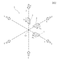
図4または図6に示すように、磁気検知部2が地球上のいずれかの場所に置かれると、磁気検知部2のX軸センサ3から地磁気の検知出力xが得られ、Y軸センサ4から地磁気の検知出力yが得られ、Z軸センサ5から地磁気の検知出力zが得られる。演算部8では、前記各検知出力x,y,zに基づいて、地磁気ベクトルVの向きが、三次元座標上の座標点データD(x,y,z)として求められる。座標点データD(x,y,z)はサンプリング周期毎に次々と得られ、データバッファに順に格納されていく。
As shown in FIG. 4 or 6, when the
図4または図6に示すように、座標点データD(x,y,z)は、三次元座標の基準原点Oを中心とする球面座標G上の点として現れる。球面座標Gの半径は、X軸方向とY軸方向およびZ軸方向での地磁気の検出強度の極大値の絶対値に比例する。したがって、球面座標Gの半径は、地磁気ベクトルVの絶対値に応じて変化する。 As shown in FIG. 4 or FIG. 6, the coordinate point data D (x, y, z) appears as a point on the spherical coordinate G centered on the reference origin O of the three-dimensional coordinate. The radius of the spherical coordinate G is proportional to the absolute value of the maximum value of the detection intensity of geomagnetism in the X-axis direction, the Y-axis direction, and the Z-axis direction. Therefore, the radius of the spherical coordinate G changes according to the absolute value of the geomagnetic vector V.
図3に示すように、角速度検知部11には、X軸ジャイロ12とY軸ジャイロ13が設けられている。X軸ジャイロ12とY軸ジャイロ13は振動型ジャイロであり、微細な寸法のMEMSで構成されている。角速度検知部11で設定されているX軸とY軸は、図2に示す磁気検知部2で設定されているX軸およびY軸と同じ向きである。
As shown in FIG. 3, the angular
X軸ジャイロ12に設けられた振動子12aは、圧電素子などでVx方向へ振動させられる。方位検知装置1が、X軸回りの角速度ωxを持つと、振動子12aにコリオリ力による振動Fxが発生する。この振動Fxの成分は、振動子12aに設けられた電極とこれに対向する固定電極との静電容量の変化などから検知される。振動Fxは図1に示す検知回路14によって検知され、検知回路14において、X軸回りの角速度ωxが算出される。
The
Y軸ジャイロ13は、振動子13aがVy方向へ振動させられ、Y軸回りの回転運動によるコリオリ力が、振動子13aの振動Fyとして検知される。検知回路14では、振動Fyの検知出力から、Y軸回りの角速度ωyが算出される。
In the Y-
検知回路14で算出されたX軸回りの角速度ωxは、図1に示す積分計算部15に与えられ、時間によって積分されて、X軸回りの回転角に変換される。同様に、検知回路14で算出されたY軸回りの角速度ωyも積分計算部15において時間で積分されてY軸回りの回転角に変換される。積分計算部15で積分されたX軸回りの回転角とY軸回りの回転角は、それぞれ演算部8に与えられA/D変換部でディジタルデータに変換され、演算部8内のメモリに蓄積されていく。
The angular velocity ωx about the X axis calculated by the
方位検知装置1が空間内で自由に運動すると、X軸回りの回転角が正方向と負方向に刻々と変化し、Y軸回りの回転角が正方向と負方向に刻々と変化する。演算部8では、メモリに蓄積されたX軸回りの回転角が積算され、図5に示すように、X軸回りの合計の角度変化量θpが算出される。同様に、メモリに蓄積されたY軸回りの回転角が積算されて、Y軸回りの合計の角度変化量θrが算出される。 When the azimuth detecting device 1 freely moves in space, the rotation angle around the X axis changes momentarily in the positive direction and the negative direction, and the rotation angle around the Y axis changes every moment in the positive direction and the negative direction. In the calculation unit 8, the rotation angles around the X axis accumulated in the memory are integrated, and the total angle change amount θp around the X axis is calculated as shown in FIG. Similarly, the rotation angles around the Y axis accumulated in the memory are integrated, and the total angle change amount θr around the Y axis is calculated.
次に、方位検知装置1による方位の検知動作を説明する。
この方位検知装置1は、電源が投入された直後または使用を開始するときに、キャリブレーションが行なわれる。キャリブレーションは、方位検知装置1を搭載した携帯機器のディスプレイに表示される指示などに基づいて行われる。キャリブレーションは、使用者が方位検知装置1を任意の方向へ数回だけ回転させることで行われる。
Next, the direction detection operation by the direction detection device 1 will be described.
The azimuth detecting device 1 is calibrated immediately after the power is turned on or when it is used. Calibration is performed based on an instruction or the like displayed on the display of a portable device in which the azimuth detecting device 1 is mounted. The calibration is performed by the user rotating the azimuth detecting device 1 several times in an arbitrary direction.
演算部8では、キャリブレーションにおいて次々に得られてデータバッファに格納される座標点データDの中からいくつかをサンプリングする。少なくとも3個の座標点データDを得ることで、座標点データDの回転軌跡に一致する円を特定できる。この円が複数個求められ、それぞれの円の中心を通り且つ円を含む平面に垂直な中心線が求められる。複数の中心線の交点を求めると、この交点が、演算部8で設定されるX−Y−Zの三次元座標の基準原点Oとなるように補正される。 The arithmetic unit 8 samples some of the coordinate point data D obtained one after another in the calibration and stored in the data buffer. By obtaining at least three coordinate point data D, it is possible to identify a circle that matches the rotation locus of the coordinate point data D. A plurality of circles are obtained, and a center line that passes through the center of each circle and is perpendicular to a plane including the circle is obtained. When the intersection of a plurality of center lines is obtained, the intersection is corrected so that it becomes the reference origin O of the three-dimensional coordinates of XYZ set by the calculation unit 8.
前記キャリブレーションの直後に、初期姿勢の設定および記憶が行われる。初期姿勢の設定と記憶は、前記ディスプレイに表示される指示などにしたがって行われる。使用者は、キャリブレーションの直後に、図4に示すように、方位検知装置1で決められているZ軸を重力の方向に向ける初期姿勢を設定する。例えば、携帯機器のディスプレイを地面と水平な姿勢にすることで、Z軸が重力の方向に向けられる。 Immediately after the calibration, the initial posture is set and stored. The initial posture is set and stored in accordance with an instruction displayed on the display. As shown in FIG. 4, the user sets an initial posture that directs the Z-axis determined by the azimuth detecting device 1 in the direction of gravity immediately after the calibration. For example, when the display of the portable device is placed in a horizontal posture with respect to the ground, the Z axis is directed in the direction of gravity.
図4には、方位検知装置1が初期姿勢に設定されたときの三次元座標が、X0軸とY0軸およびZ0軸で示されている。このとき、X軸センサ3とY軸センサ4およびZ軸センサ5で検知された地磁気ベクトルVの向きが、X0−Y0−Z0軸の三次元座標上で初期座標点データDa(xa,ya,za)として得られる。初期姿勢が設定された後に、使用者がいずれかの操作釦を押すと、演算部8において、初期姿勢での地磁気ベクトルVの向きを検知した初期座標点データDa(xa,ya,za)がメモリに記憶される。
In FIG. 4, the three-dimensional coordinates when the azimuth detecting device 1 is set to the initial posture are indicated by the X0 axis, the Y0 axis, and the Z0 axis. At this time, the orientation of the geomagnetic vector V detected by the
なお、方位検知装置1と共に加速度センサが搭載されている携帯機器では、キャリブレーションが完了し、三次元座標の基準原点Oが補正されたときに、加速度センサによって重力の向きが解るため、方位検知装置1を搭載した携帯機器などを所定の姿勢に設定しなくても、初期姿勢の設定と記憶を行うことができる。すなわち、キャリブレーションが完了して三次元座標の基準原点Oが補正されたときに、演算部8で設定される三次元座標のZ0軸の向きを重力方向に向く補正を自動的に行なうことができる。さらに、補正後のX0−Y0−Z0座標で得られた初期座標点データDa(xa,ya,za)を、自動的にメモリに記憶させることも可能である。 In the portable device in which the acceleration sensor is mounted together with the direction detection device 1, the direction of gravity is detected by the acceleration sensor when calibration is completed and the reference origin O of the three-dimensional coordinates is corrected. The initial posture can be set and stored without setting the mobile device equipped with the device 1 to a predetermined posture. That is, when calibration is completed and the reference origin O of the three-dimensional coordinate is corrected, correction that automatically sets the direction of the Z0 axis of the three-dimensional coordinate set by the calculation unit 8 in the direction of gravity can be automatically performed. it can. Furthermore, the initial coordinate point data Da (xa, ya, za) obtained with the corrected X0-Y0-Z0 coordinates can be automatically stored in the memory.
初期姿勢の設定と記憶が完了した後に、方位検知装置1を搭載した携帯機器などを空間内で自由に動かすと、方位検知装置1に設定されているX−Y−Z軸の三次元座標が、図4に示す初期姿勢のときのX0−Y0−Z0軸の三次元座標に対して各方向へ傾くことになる。ただし、積分計算部15では、X軸ジャイロ12とY軸ジャイロ13で検出されて刻々と変化するX軸回りの角速度とY軸回りの角速度がそれぞれ積分されて回転角に変換され、さらに、演算部8で、前記回転角が積算されて、X軸回りの角度変化量θpとY軸回りの角度変化量θrが算出されている。この角度変化量θpとθrは、図4に示す初期姿勢が設定された後の、初期姿勢を起点とするX軸回りとY軸回りの回転角の合計を意味している。
After the setting and storage of the initial posture is completed, when the portable device equipped with the azimuth detecting device 1 is freely moved in the space, the three-dimensional coordinates of the XYZ axes set in the azimuth detecting device 1 are obtained. 4 is inclined in each direction with respect to the three-dimensional coordinates of the X0-Y0-Z0 axes in the initial posture shown in FIG. However, in the
したがって、磁場データ検知部6で検知されて球面座標G上の座標点データDとして認識される地磁気ベクトルVの方位の検出や、地磁気ベクトルVと方位検知装置1との相対的な移動量などを、積分された角度変化量θpとθrを使用して補正することが可能である。 Therefore, the detection of the azimuth of the geomagnetic vector V detected by the magnetic field data detection unit 6 and recognized as the coordinate point data D on the spherical coordinate G, the relative movement amount between the geomagnetic vector V and the azimuth detection device 1, etc. It is possible to correct using the integrated angle change amounts θp and θr.
方位検出における補正方法の一例を以下に説明する。
演算部8では、積分された角度変化量θpとθrの値が得られているときに、三次元座標の向きを、X軸回りに角度変化量θpだけ戻し、Y軸回りに角度変化量θrだけ戻す演算が行われる。この演算は、一定時間を空けて定期的に行われ、または、新たな座標点データDが取得される度に行われる。図5に示すように、この演算により、三次元座標のX−Yの平面座標を、図4に示す初期姿勢のときのX0−Y0の平面座標と同じ面に戻すことができる。
An example of a correction method in azimuth detection will be described below.
The arithmetic unit 8 returns the direction of the three-dimensional coordinates by the angle change amount θp around the X axis and the angle change amount θr around the Y axis when the integrated values of the angle change amounts θp and θr are obtained. An operation that returns only is performed. This calculation is performed periodically after a certain period of time, or is performed every time new coordinate point data D is acquired. As shown in FIG. 5, by this calculation, the three-dimensional XY plane coordinates can be returned to the same plane as the X0-Y0 plane coordinates in the initial posture shown in FIG.
ただし、Z軸回りの角度変化量は積算しておらずZ軸回りの角度変化量を加味していないので、三次元座標の向きを、X軸回りに角度変化量θpだけ戻し、Y軸回りに角度変化量θrだけ戻した時点で、Z軸周りの角度変化量だけが残る。図5には、角度変化量θp,θrだけ三次元座標を戻した後のX−Y座標の座標軸をX1軸とY1軸で示している。X1軸とY1軸は、初期姿勢のときのX0軸とY0軸から角度αだけ回動している。この角度αが、初期姿勢を起点とした方位検知装置1と地磁気ベクトルVとの方位角の変化量である。 However, since the angle change amount around the Z axis is not integrated and the angle change amount around the Z axis is not taken into account, the direction of the three-dimensional coordinates is returned by the angle change amount θp around the X axis, and the Y axis around When the angle change amount θr is returned to, only the angle change amount around the Z axis remains. In FIG. 5, the coordinate axes of the XY coordinates after returning the three-dimensional coordinates by the angle change amounts θp and θr are indicated by the X1 axis and the Y1 axis. The X1 axis and the Y1 axis are rotated by an angle α from the X0 axis and the Y0 axis in the initial posture. This angle α is the amount of change in the azimuth angle between the azimuth detecting device 1 and the geomagnetic vector V starting from the initial posture.
図6には、X軸回りに角度変化量θpだけ戻し、Y軸回りに角度変化量θrだけ戻した後の三次元座標がX1−Y1−Z0軸で示されている。この三次元座標X1−Y1−Z0で得られた最新の座標点データをDb(xb,yb,za)とする。この座標点データDbと、図4に示す初期姿勢のときに得られた初期座標点データDa(xa,ya,za)とでは、Z軸座標(za)が同じである。最新の座標点データDbのX−Y座標成分(xb,yb)と初期座標点データDaのX−Y座標成分(xa,ya)とから、地磁気ベクトルVの方位の変化角αを求めることができる。 In FIG. 6, the three-dimensional coordinates after returning the angle change amount θp around the X axis and returning the angle change amount θr around the Y axis are shown by the X1-Y1-Z0 axes. The latest coordinate point data obtained with the three-dimensional coordinates X1-Y1-Z0 is defined as Db (xb, yb, za). The coordinate point data Db and the initial coordinate point data Da (xa, ya, za) obtained in the initial posture shown in FIG. 4 have the same Z-axis coordinate (za). The change angle α of the orientation of the geomagnetic vector V can be obtained from the XY coordinate component (xb, yb) of the latest coordinate point data Db and the XY coordinate component (xa, ya) of the initial coordinate point data Da. it can.
演算部8では、以下の数1に示す行列式で演算を行うことで、X軸回りに角度変化量θpだけ戻し、Y軸回りに角度変化量θrだけ戻したあとの三次元座標上での座標点データDb(xb,yb,za)を演算することができる。 The calculation unit 8 performs the calculation using the determinant shown in the following Equation 1, thereby returning the angle change amount θp around the X axis and the angle change amount θr around the Y axis on the three-dimensional coordinates. Coordinate point data Db (xb, yb, za) can be calculated.
数1のxθ,yθ,zθは、測定時点すなわち、三次元座標が任意に傾いたときに得られる最新の座標点データDθ(xθ,yθ,zθ)であり、この値を行列式に代入することで、座標点データDb(xb,yb,za)を得ることができる。この座標点データDb(xb,yb,za)と、初期座標点データDa(xa,ya,za)とから方位の変化角αを求めることができる。 Xθ, yθ, zθ in Equation 1 is the latest coordinate point data Dθ (xθ, yθ, zθ) obtained at the time of measurement, that is, when the three-dimensional coordinate is arbitrarily tilted, and this value is substituted into the determinant. Thus, the coordinate point data Db (xb, yb, za) can be obtained. From this coordinate point data Db (xb, yb, za) and initial coordinate point data Da (xa, ya, za), the azimuth change angle α can be obtained.

上記の方位の演算では、方位検知装置1を地磁気ベクトルVの向きを検知するためだけに機能させ、角速度検知部11を角速度を検知するためだけに機能させているため、磁気検知部2のノイズや、角速度検知装置の温度特性のドラフトを互いに補完し合って、精度の良い方位の変化を求めることができる。
In the above calculation of the azimuth, since the azimuth detecting device 1 functions only for detecting the direction of the geomagnetic vector V and the angular
本発明の方位検知装置は、3軸の磁気センサからの座標点データと角速度検知部で得られた角速度を使用して、方位の変化や姿勢の変化を算出することができる。よって、地磁気の方位計として使用できる。さらに地磁気以外の外部磁界の磁気ベクトルの動きを検知する装置として使用可能である。例えば磁気検知装置を固定し、外部の磁気ベクトルがどの方向でどのような運動をしているかの検知も可能である。また、携帯用のゲーム装置の姿勢検知や、ゲーム装置用の入力装置の姿勢検知や、ロボットの腕や関節などの姿勢の変化を検知する検知部として使用することができる。 The azimuth detecting device of the present invention can calculate a change in azimuth and a change in posture using coordinate point data from a three-axis magnetic sensor and the angular velocity obtained by the angular velocity detector. Therefore, it can be used as a geomagnetic compass. Further, it can be used as a device for detecting the motion of a magnetic vector of an external magnetic field other than geomagnetism. For example, it is possible to fix the magnetic detection device and detect what direction and how the external magnetic vector moves. Further, it can be used as a detection unit for detecting the posture of a portable game device, detecting the posture of an input device for a game device, or detecting a change in posture of a robot arm or joint.
1 方位検知装置
2 磁気検知部
3 X軸センサ
4 Y軸センサ
5 Z軸センサ
6 磁場データ検知部
7 メモリ
8 演算部
11 角速度検知部
12 X軸ジャイロ
13 Y軸ジャイロ
14 検知回路
15 積分計算部
Da 初期姿勢の座標点データ
Db X軸回りの角度変化量とY軸回りの角度変化量を復元したときの座標点データ
X0−Y0−Z0 初期姿勢の三次元座標
X1−Y1−Z0 軸回りの角度変化量とY軸回りの角度変化量を復元したときの三次元座標
V 地磁気ベクトル
θp,θr 角度変化量
DESCRIPTION OF SYMBOLS 1
Claims (5)
前記磁気検知部に、X軸が磁気の方向に向けられたときに検知出力の絶対値が極大値となるX軸センサと、Y軸が磁気の方向に向けられたときに検知出力の絶対値が極大値となるY軸センサ、およびZ軸が磁気の方向に向けられたときに検知出力の絶対値が極大値となるZ軸センサが搭載され、
前記演算部で、
(a)前記X軸センサと前記Y軸センサおよび前記Z軸センサの検知出力に基づいて、磁気ベクトルの向きを三次元座標上の座標点データとして求め、
(b)前記角速度検知部で検知されたX軸回りの角速度とY軸回りの角速度をそれぞれ積分して、初期姿勢を起点とするX軸回りの角度変化量θpおよびY軸回りの角度変化量θrを求め、
(c)測定時の座標点データを得たときに、それまでの前記角度変化量θpおよび前記角度変化量θrを用いて、前記角度変化量θp,θrだけ三次元座標を戻す補正を行い、補正後の三次元座標上での座標点データと初期姿勢のときに得られた初期座標点データとから、Z軸回りの磁気ベクトルの相対的な角度変化量αを求めることを特徴とする方位検知装置。 A magnetic detection unit in which an X axis, a Y axis, and a Z axis orthogonal to each other are determined as reference axes, an angular velocity detection unit that detects an angular velocity around the X axis and an angular velocity around the Y axis, and a calculation unit;
An X-axis sensor in which the absolute value of the detection output becomes a maximum value when the X-axis is directed to the magnetic direction and the absolute value of the detection output when the Y-axis is directed to the magnetic direction. Is equipped with a Y-axis sensor in which the maximum value is detected, and a Z-axis sensor in which the absolute value of the detection output is maximized when the Z-axis is directed in the magnetic direction,
In the calculation unit,
(A) Based on detection outputs of the X-axis sensor, the Y-axis sensor, and the Z-axis sensor, the direction of a magnetic vector is obtained as coordinate point data on three-dimensional coordinates,
(B) The angular velocity around the X axis detected by the angular velocity detector and the angular velocity around the Y axis are integrated, and the angular variation θp around the X axis starting from the initial posture and the angular variation around the Y axis. Find θr ,
(C) When the coordinate point data at the time of measurement is obtained, using the angle change amount θp and the angle change amount θr so far, correction is performed to return the three-dimensional coordinates by the angle change amounts θp and θr, The relative angle change α of the magnetic vector around the Z axis is obtained from the coordinate point data on the corrected three-dimensional coordinates and the initial coordinate point data obtained in the initial posture. Detection device.
Priority Applications (1)
| Application Number | Priority Date | Filing Date | Title |
|---|---|---|---|
| JP2010053534A JP5457890B2 (en) | 2010-03-10 | 2010-03-10 | Orientation detection device |
Applications Claiming Priority (1)
| Application Number | Priority Date | Filing Date | Title |
|---|---|---|---|
| JP2010053534A JP5457890B2 (en) | 2010-03-10 | 2010-03-10 | Orientation detection device |
Publications (2)
| Publication Number | Publication Date |
|---|---|
| JP2011185868A JP2011185868A (en) | 2011-09-22 |
| JP5457890B2 true JP5457890B2 (en) | 2014-04-02 |
Family
ID=44792324
Family Applications (1)
| Application Number | Title | Priority Date | Filing Date |
|---|---|---|---|
| JP2010053534A Expired - Fee Related JP5457890B2 (en) | 2010-03-10 | 2010-03-10 | Orientation detection device |
Country Status (1)
| Country | Link |
|---|---|
| JP (1) | JP5457890B2 (en) |
Families Citing this family (4)
| Publication number | Priority date | Publication date | Assignee | Title |
|---|---|---|---|---|
| JP5511088B2 (en) * | 2011-03-30 | 2014-06-04 | Kddi株式会社 | Portable device, program and method for correcting gravity vector used for autonomous positioning |
| CN104567881A (en) * | 2014-12-26 | 2015-04-29 | 北京控制工程研究所 | Patrol device position posture determining method based on gravity vectors of sun, earth core and lunar surface |
| US11754394B2 (en) * | 2019-08-21 | 2023-09-12 | SeeHow Pte. Ltd. | Systems and methods for measuring the rate of angular displacement using magnetic field sensing |
| CN112386209B (en) * | 2020-10-08 | 2022-12-06 | 哈尔滨工业大学 | Positioning precision improving method based on movable magnetic gradiometer |
Family Cites Families (6)
| Publication number | Priority date | Publication date | Assignee | Title |
|---|---|---|---|---|
| JPH02238336A (en) * | 1989-03-10 | 1990-09-20 | Ricoh Co Ltd | Attitude sensor |
| JPH0571964A (en) * | 1991-09-10 | 1993-03-23 | Pioneer Electron Corp | Vehicle azimuth detector |
| JPH08178687A (en) * | 1994-12-26 | 1996-07-12 | Pioneer Electron Corp | Posture detecting method, and device therefor |
| JPH11325904A (en) * | 1998-05-20 | 1999-11-26 | Japan Aviation Electronics Ind Ltd | Earth magnetism azimuth sensor |
| JP2000356519A (en) * | 1999-06-16 | 2000-12-26 | Japan Aviation Electronics Industry Ltd | Magnetic direction sensor |
| JP2006275523A (en) * | 2005-03-28 | 2006-10-12 | Citizen Watch Co Ltd | Electronic azimuth device and recording medium |
-
2010
- 2010-03-10 JP JP2010053534A patent/JP5457890B2/en not_active Expired - Fee Related
Also Published As
| Publication number | Publication date |
|---|---|
| JP2011185868A (en) | 2011-09-22 |
Similar Documents
| Publication | Publication Date | Title |
|---|---|---|
| JP3848941B2 (en) | Geomagnetic sensor attitude error compensation apparatus and method | |
| JPWO2007099599A1 (en) | Magnetic gyro | |
| JP4890660B2 (en) | Geomagnetic detector | |
| JP7025215B2 (en) | Positioning system and positioning method | |
| JP4599502B1 (en) | Magnetic gyro | |
| JP5678357B2 (en) | Rotation information calculation method, rotation information calculation program, magnetic gyroscope and moving body | |
| JP5457890B2 (en) | Orientation detection device | |
| JP2005061969A (en) | Azimuthal angle measuring instrument and azimuthal angle measuring method | |
| JP5374422B2 (en) | Magnetic field detector | |
| CN108592902A (en) | A kind of positioning device and localization method based on multisensor, system and mechanical arm | |
| JP5475873B2 (en) | Geomagnetic detector | |
| JP2006275523A (en) | Electronic azimuth device and recording medium | |
| JP5425671B2 (en) | Magnetic field detector | |
| JP5144701B2 (en) | Magnetic field detector | |
| JP5490576B2 (en) | Magnetic field detector | |
| JP5498209B2 (en) | Magnetic field detector | |
| JP5498208B2 (en) | Magnetic field detector | |
| JP5341861B2 (en) | Magnetic field detector | |
| JP5498196B2 (en) | Magnetic field detector | |
| JP4648423B2 (en) | Rotation angle measurement device and rotation angle measurement method | |
| Bai | 3D Orientation Estimation Using Inertial Sensors | |
| JP2011185861A (en) | Geomagnetism detector | |
| Li et al. | Development of Electronic Compass for Indoor Mobile Robot | |
| JP2011169656A (en) | Device for detection of magnetic field | |
| JP2010281837A (en) | Magnetic gyroscope |
Legal Events
| Date | Code | Title | Description |
|---|---|---|---|
| A621 | Written request for application examination |
Free format text: JAPANESE INTERMEDIATE CODE: A621 Effective date: 20120925 |
|
| A131 | Notification of reasons for refusal |
Free format text: JAPANESE INTERMEDIATE CODE: A131 Effective date: 20130910 |
|
| A521 | Written amendment |
Free format text: JAPANESE INTERMEDIATE CODE: A523 Effective date: 20131107 |
|
| TRDD | Decision of grant or rejection written | ||
| A01 | Written decision to grant a patent or to grant a registration (utility model) |
Free format text: JAPANESE INTERMEDIATE CODE: A01 Effective date: 20140107 |
|
| A61 | First payment of annual fees (during grant procedure) |
Free format text: JAPANESE INTERMEDIATE CODE: A61 Effective date: 20140110 |
|
| R150 | Certificate of patent or registration of utility model |
Ref document number: 5457890 Country of ref document: JP Free format text: JAPANESE INTERMEDIATE CODE: R150 Free format text: JAPANESE INTERMEDIATE CODE: R150 |
|
| S533 | Written request for registration of change of name |
Free format text: JAPANESE INTERMEDIATE CODE: R313533 |
|
| R350 | Written notification of registration of transfer |
Free format text: JAPANESE INTERMEDIATE CODE: R350 |
|
| LAPS | Cancellation because of no payment of annual fees |