JP5678357B2 - Rotation information calculation method, rotation information calculation program, magnetic gyroscope and moving body - Google Patents
Rotation information calculation method, rotation information calculation program, magnetic gyroscope and moving body Download PDFInfo
- Publication number
- JP5678357B2 JP5678357B2 JP2014509966A JP2014509966A JP5678357B2 JP 5678357 B2 JP5678357 B2 JP 5678357B2 JP 2014509966 A JP2014509966 A JP 2014509966A JP 2014509966 A JP2014509966 A JP 2014509966A JP 5678357 B2 JP5678357 B2 JP 5678357B2
- Authority
- JP
- Japan
- Prior art keywords
- vector
- rotation
- rotation axis
- magnetic
- angular velocity
- Prior art date
- Legal status (The legal status is an assumption and is not a legal conclusion. Google has not performed a legal analysis and makes no representation as to the accuracy of the status listed.)
- Active
Links
- 230000005291 magnetic effect Effects 0.000 title claims description 131
- 238000004364 calculation method Methods 0.000 title claims description 69
- 239000013598 vector Substances 0.000 claims description 402
- 230000001133 acceleration Effects 0.000 claims description 61
- 230000005389 magnetism Effects 0.000 claims description 22
- 230000008014 freezing Effects 0.000 claims description 12
- 238000007710 freezing Methods 0.000 claims description 12
- 230000007704 transition Effects 0.000 claims description 12
- 238000005259 measurement Methods 0.000 claims description 9
- 238000012545 processing Methods 0.000 claims description 5
- 238000012937 correction Methods 0.000 claims description 4
- 230000003068 static effect Effects 0.000 claims description 2
- 238000005096 rolling process Methods 0.000 claims 1
- 230000014509 gene expression Effects 0.000 description 22
- 238000000034 method Methods 0.000 description 7
- 238000001514 detection method Methods 0.000 description 5
- 238000004422 calculation algorithm Methods 0.000 description 4
- 230000005484 gravity Effects 0.000 description 4
- 238000010586 diagram Methods 0.000 description 3
- 238000013459 approach Methods 0.000 description 2
- 230000007423 decrease Effects 0.000 description 2
- 230000000694 effects Effects 0.000 description 2
- 238000002474 experimental method Methods 0.000 description 2
- 230000002093 peripheral effect Effects 0.000 description 2
- 238000011160 research Methods 0.000 description 2
- XUIMIQQOPSSXEZ-UHFFFAOYSA-N Silicon Chemical compound [Si] XUIMIQQOPSSXEZ-UHFFFAOYSA-N 0.000 description 1
- 238000007796 conventional method Methods 0.000 description 1
- 230000005294 ferromagnetic effect Effects 0.000 description 1
- 230000003014 reinforcing effect Effects 0.000 description 1
- 230000004043 responsiveness Effects 0.000 description 1
- 238000005070 sampling Methods 0.000 description 1
- 230000035945 sensitivity Effects 0.000 description 1
- 229910052710 silicon Inorganic materials 0.000 description 1
- 239000010703 silicon Substances 0.000 description 1
- 239000000758 substrate Substances 0.000 description 1
- 230000001052 transient effect Effects 0.000 description 1
Images


Classifications
-
- G—PHYSICS
- G01—MEASURING; TESTING
- G01C—MEASURING DISTANCES, LEVELS OR BEARINGS; SURVEYING; NAVIGATION; GYROSCOPIC INSTRUMENTS; PHOTOGRAMMETRY OR VIDEOGRAMMETRY
- G01C19/00—Gyroscopes; Turn-sensitive devices using vibrating masses; Turn-sensitive devices without moving masses; Measuring angular rate using gyroscopic effects
- G01C19/02—Rotary gyroscopes
- G01C19/04—Details
- G01C19/32—Indicating or recording means specially adapted for rotary gyroscopes
-
- G—PHYSICS
- G01—MEASURING; TESTING
- G01C—MEASURING DISTANCES, LEVELS OR BEARINGS; SURVEYING; NAVIGATION; GYROSCOPIC INSTRUMENTS; PHOTOGRAMMETRY OR VIDEOGRAMMETRY
- G01C19/00—Gyroscopes; Turn-sensitive devices using vibrating masses; Turn-sensitive devices without moving masses; Measuring angular rate using gyroscopic effects
- G01C19/58—Turn-sensitive devices without moving masses
-
- G—PHYSICS
- G01—MEASURING; TESTING
- G01B—MEASURING LENGTH, THICKNESS OR SIMILAR LINEAR DIMENSIONS; MEASURING ANGLES; MEASURING AREAS; MEASURING IRREGULARITIES OF SURFACES OR CONTOURS
- G01B7/00—Measuring arrangements characterised by the use of electric or magnetic techniques
- G01B7/30—Measuring arrangements characterised by the use of electric or magnetic techniques for measuring angles or tapers; for testing the alignment of axes
-
- G—PHYSICS
- G01—MEASURING; TESTING
- G01C—MEASURING DISTANCES, LEVELS OR BEARINGS; SURVEYING; NAVIGATION; GYROSCOPIC INSTRUMENTS; PHOTOGRAMMETRY OR VIDEOGRAMMETRY
- G01C25/00—Manufacturing, calibrating, cleaning, or repairing instruments or devices referred to in the other groups of this subclass
- G01C25/005—Manufacturing, calibrating, cleaning, or repairing instruments or devices referred to in the other groups of this subclass initial alignment, calibration or starting-up of inertial devices
-
- G—PHYSICS
- G01—MEASURING; TESTING
- G01D—MEASURING NOT SPECIALLY ADAPTED FOR A SPECIFIC VARIABLE; ARRANGEMENTS FOR MEASURING TWO OR MORE VARIABLES NOT COVERED IN A SINGLE OTHER SUBCLASS; TARIFF METERING APPARATUS; MEASURING OR TESTING NOT OTHERWISE PROVIDED FOR
- G01D5/00—Mechanical means for transferring the output of a sensing member; Means for converting the output of a sensing member to another variable where the form or nature of the sensing member does not constrain the means for converting; Transducers not specially adapted for a specific variable
- G01D5/12—Mechanical means for transferring the output of a sensing member; Means for converting the output of a sensing member to another variable where the form or nature of the sensing member does not constrain the means for converting; Transducers not specially adapted for a specific variable using electric or magnetic means
Description
本発明は、地磁気などの基準磁気を利用して、携帯端末等のように姿勢が変動し得る移動体の角速度、回転速度、回転角などの回転情報を極短時間で取得可能な回転情報演算方法に関する。また本発明は、その方法を実行できる回転情報演算プログラム、そのプログラムを備えた磁気型ジャイロスコープおよびそれを備えた移動体に関する。 The present invention uses a reference magnetism such as geomagnetism to calculate rotation information that can acquire rotation information such as angular velocity, rotation speed, rotation angle, etc. of a mobile object whose posture can be changed, such as a portable terminal, in an extremely short time. Regarding the method. The present invention also relates to a rotation information calculation program capable of executing the method, a magnetic gyroscope including the program, and a moving body including the magnetic gyroscope.
航空機、船舶、自動車等のみならず、携帯電話、スマートホン、タブレット端末などの携帯情報端末、カーナビゲーションなどの位置情報端末、デジタルカメラ等の電子器機などでも、自身の姿勢(方位、向き、傾き等)やその変化を精確にかつリアルタイムに把握することが求められており、移動体の回転情報(特に角速度)を的確かつ迅速に検出または測定することが不可欠となっている。 Not only aircraft, ships, automobiles, etc., but also mobile information terminals such as mobile phones, smart phones and tablet terminals, position information terminals such as car navigation systems, electronic devices such as digital cameras, etc. Etc.) and their changes accurately and in real time are required, and it is indispensable to accurately detect and measure the rotation information (especially angular velocity) of the moving body.
角速度を検出できるセンサとして、振動型ジャイロスコープが知られており、これを携帯端末等に組み込めるサイズに小型化したMEMS(Micro Electro Mechanical Systems)ジャイロセンサーが多用されている。このジャイロセンサーは、例えば、シリコン基板を櫛歯状に微細加工した振動子(質量m)からなる。電気的に共振(振動速度v)している振動子へ角速度(ω)が印加されると、振動子の振動方向と回転軸方向の両方に直交する方向へコリオリ力(2mvω)が作用し、振動子の櫛歯間の静電容量が変化する。この静電容量の変化を検出することにより、角速度がリアルタイムで検出され得る。この検出された角速度を積分すれば、所定時間内の回転角も求まり、移動体の姿勢変動を把握することが可能となる。 A vibration type gyroscope is known as a sensor that can detect angular velocity, and a MEMS (Micro Electro Mechanical Systems) gyro sensor that is miniaturized to a size that can be incorporated into a portable terminal or the like is widely used. This gyro sensor includes, for example, a vibrator (mass m) obtained by finely processing a silicon substrate into a comb-like shape. When an angular velocity (ω) is applied to a vibrator that is electrically resonating (vibration velocity v), a Coriolis force (2 mvω) acts in a direction perpendicular to both the vibration direction and the rotation axis direction of the vibrator, The capacitance between the comb teeth of the vibrator changes. By detecting this change in capacitance, the angular velocity can be detected in real time. By integrating the detected angular velocities, the rotation angle within a predetermined time can also be obtained, and the posture change of the moving body can be grasped.
ところが、このようなジャイロセンサーは、携帯端末等に同時に組み込まれる磁気センサーや加速度センサーに比べて高価である。また、角速度の検出にはその振動子を電気的に常時振動させておく必要があり、消費電力が大きくなる。さらに、その振動子は、回転運動以外の力学的な振動や衝撃等にも反応するため、MEMSジャイロセンサーだけでは必ずしも角速度を精確に検出できるものではなかった。 However, such a gyro sensor is more expensive than a magnetic sensor and an acceleration sensor that are simultaneously incorporated in a portable terminal or the like. In addition, the angular velocity needs to be oscillated electrically at all times, which increases power consumption. Furthermore, since the vibrator responds to mechanical vibrations and impacts other than the rotational motion, the MEMS gyro sensor alone cannot always accurately detect the angular velocity.
そこで、MEMSジャイロセンサー等による角速度等の検出を、磁気センサーで代替することにより、携帯端末等の小型化、省電力化、低コスト化さらには姿勢情報の検出精度向上等を図ることが考えられている。これに関連する記載が、例えば、下記の特許文献にある。 In view of this, it is conceivable that the detection of angular velocity or the like by the MEMS gyro sensor or the like is replaced by a magnetic sensor to reduce the size, power consumption, cost, and improve the accuracy of detecting posture information, etc. ing. The description relevant to this is, for example, in the following patent document.
特許文献1は、被測定体に固定された3軸直交座標系で地磁気を検出して得られた3時点以上の磁気ベクトルに基づいて、回転軸とその回転軸を中心とした回転角度とその回転角度から求まる回転角速度を算出できる磁気式ジャイロを提案している。この磁気式ジャイロを用いれば、MEMSジャイロセンサー等を省略しても回転情報を取得することが可能となる。
もっとも、特許文献1では、ある時点の回転情報を取得するために、それ以前に取得した3時点の磁気ベクトルを必要としており、得られる回転情報はいわば3時点における回転状態を平均化したものに過ぎない。また、その算出精度を向上させるためには、それら3時点で形成される扇形の面積を十分に大きく確保する必要がある。換言するなら磁気ベクトルのサンプリング間隔を大きくする必要がある。これでは算出時間が長くなり、移動体の姿勢変化に追従した迅速な回転情報の取得が困難となる。具体的にいうと、特許文献1にあるような磁気式ジャイロを用いた場合、MEMSジャイロセンサーを用いた場合と比較して、100〜200ms程度の測定遅れを生じ得る。一般に端末のスクリーン画面は16ms程度で変化するため、100ms以上の遅れは操作者にとって無視できない遅れとなる。従って、磁気型ジャイロスコープの実用化を図るには、その遅れを16ms以下に抑制することが重要となる。
However, in
本発明はこのような事情に鑑みて為されたものであり、従来のジャイロセンサー等を用いるまでもなく、磁気センサーから得られる磁気情報に基づいて、各種の移動体の回転情報を素早く取得できる回転情報演算方法と、その方法を実行できる回転情報演算プログラム、そのプログラムを備えた磁気型ジャイロスコープおよびそれを備えた移動体を提供することを目的とする。 The present invention has been made in view of such circumstances, and it is possible to quickly obtain rotation information of various moving bodies based on magnetic information obtained from a magnetic sensor without using a conventional gyro sensor or the like. An object of the present invention is to provide a rotation information calculation method, a rotation information calculation program capable of executing the method, a magnetic gyroscope including the program, and a moving body including the magnetic gyroscope.
本発明者はこの課題を解決すべく鋭意研究し、試行錯誤を重ねた結果、従来と異なり、2時点の磁気ベクトルを用いて、現時点における角速度ベクトルをほぼ瞬間的に算出できる新たなアルゴリズム(回転情報演算方法)を考案した。この成果を発展させることにより、以降に述べる本発明を完成するに至った。 As a result of extensive research and trial and error, the present inventor has conducted a new algorithm (rotation) that can calculate the angular velocity vector at the present moment almost instantaneously by using magnetic vectors at two points of time unlike conventional methods. An information calculation method was devised. By developing this result, the present invention described below has been completed.
《回転情報演算方法》
(1)本発明の回転情報演算方法は、向きと大きさが安定な基準磁気を連続的に測定して三次元の磁気成分からなる磁気ベクトルを微小時間毎に取得する磁気ベクトル取得ステップと、第一時刻(ti)で取得された第一磁気ベクトル(Hi)と、該第一磁気ベクトル(Hi)と該第一時刻よりも微小時間(Δt)前である第二時刻(ti−1=ti−Δt)で取得された第二磁気ベクトル(Hi−1)との差分である第一差分ベクトル(ΔHi=Hi−Hi−1)との外積(Hi×ΔHi)を用いて仮性角速度ベクトル(ωpr)を算出する仮性角速度ベクトル算出ステップと、該第一時刻における回転軸を指標する回転軸ベクトル(n)を特定する回転軸ベクトル特定ステップと、該第一磁気ベクトル(Hi)と該回転軸ベクトル(n)のなす角である差角(αi)または該差角を指標する差角指標値を算出する差角算出ステップと、該仮性角速度ベクトル(ωpr)の大きさと該差角または該差角指標値と該回転軸ベクトル(n)を用いて該第一時刻における真性角速度ベクトル(ωth)を算出する真性角速度ベクトル算出ステップとを備え、
前記回転軸ベクトル特定ステップは、移動体が回転軸を変化させつつ回転運動をする自由軸回転モードにあるとき、前記第二時刻(t i−1 )における回転軸ベクトル(n i−1 )を用いた回転座標系により表現された前記第一時刻(t i )における瞬間回転中心(O * )から前記第一磁気ベクトル(H i )の終点に向かう動径ベクトル(Hr)と、該第一磁気ベクトル(H i )と、前記第一差分ベクトル(ΔH i )とを用いて、該回転軸ベクトル(n i−1 )に対する傾きをフィードバック演算により修正して回転軸ベクトル(n i )を特定するステップであり、
前記回転座標系は、前記第一時刻(t i )における回転軸ベクトル(n i )を近接している前記第二時刻(t i−1 )における回転軸ベクトル(n i−1 )と仮定( n i =n i−1 )して、e n =n i−1 とした軸方向の基本ベクトル(e n )と、該第一磁気ベクトル(H i )と前記差角(α i )から求めた前記動径方向ベクトル(Hr)の基本ベクトル(e r )と、該基本ベクトル(e n )と該基本ベクトル(e r )の外積(e n × e r )から求まる進行方向の基本ベクトル(e v )と、により該第一時刻(t i )において定義される瞬間座標系(e n , e v , e r )であり、
前記回転軸ベクトル(n i )と、前記差角(α i )または前記差角指標値と、前記仮性角速度ベクトル(ω pr )とにより、下式(式10)から求まる前記真性角速度ベクトル(ωth)を用いて前記移動体に関する回転情報を求めることを特徴とする回転情報演算方法。
ω th = (|ω pr |/sinα i )・n i (式10)
《Rotation information calculation method》
(1) A rotation information calculation method according to the present invention includes a magnetic vector acquisition step of continuously measuring a reference magnetism having a stable direction and size and acquiring a magnetic vector composed of a three-dimensional magnetic component every minute time; The first magnetic vector (H i ) acquired at the first time (t i ), and the second time (t) that is a minute time (Δt) before the first magnetic vector (H i ) and the first time. The outer product (H i ) with the first difference vector (ΔH i = H i −H i−1 ), which is the difference from the second magnetic vector (H i−1 ) acquired at i−1 = t i −Δt). A pseudo angular velocity vector calculation step of calculating a pseudo angular velocity vector (ω pr ) using × ΔH i ), a rotation axis vector specifying step of specifying a rotation axis vector (n) that indicates the rotation axis at the first time, said first magnetic vector (H i) and said rotary shaft The difference angle calculating step of calculating a difference angle (alpha i) or the difference angle index value indicative of the difference angle is an angle formed vector (n), the size of the temporary property angular velocity vector (omega pr) and the difference angle or An intrinsic angular velocity vector calculating step of calculating an intrinsic angular velocity vector (ω th ) at the first time using the difference angle index value and the rotation axis vector (n),
In the rotation axis vector specifying step, the rotation axis vector (n i-1 ) at the second time (t i-1 ) is obtained when the moving body is in a free axis rotation mode in which the rotation is performed while changing the rotation axis. A radial vector (Hr) from the instantaneous center of rotation (O * ) at the first time (t i ) expressed by the rotational coordinate system used toward the end point of the first magnetic vector (H i ); Using the magnetic vector (H i ) and the first difference vector (ΔH i ), the inclination with respect to the rotation axis vector (n i−1 ) is corrected by feedback calculation to identify the rotation axis vector (n i ). Is a step to
The rotation coordinate system is assumed to be a rotation axis vector (n i-1 ) at the second time (t i-1 ) close to the rotation axis vector (n i ) at the first time (t i ) ( n i = n i-1 ), and obtained from the basic vector (e n ) in the axial direction where e n = n i-1 , the first magnetic vector (H i ), and the difference angle (α i ). basic vector (e r) and, the basic vector (e n) and the basic vector (e r) of the outer product (e n × e r) the traveling direction of the basis vectors obtained from the radial vector (Hr) was ( e v ), and an instantaneous coordinate system (e n , e v , e r ) defined at the first time (t i ) by
The intrinsic angular velocity vector (ω ) obtained from the following equation (Equation 10) using the rotation axis vector (n i ), the difference angle (α i ) or the difference angle index value, and the pseudo angular velocity vector (ω pr ). rotation information calculation method characterized by determining the rotating information about the movable body using th).
ω th = (| ω pr | / sin α i ) · n i (Equation 10)
(2)本発明の回転情報演算方法では、移動体の回転速度(真性角速度ベクトル:ωth)を、その大きさ(|ωth|)とその方向(回転軸ベクトル:n)に分けて求めている。ここで、その大きさ(|ωth|)は仮性角速度ベクトル(ωpr)および差角指標値から算出される。その方向は、移動体の回転状況(回転モード)に応じて、適切な回転軸ベクトル(n)が算出される。これにより、移動体の回転軸が変動する場合でも、実質的な遅れを感じさせることなく、精確な回転情報の演算が可能となる。(2) In the rotation information calculation method of the present invention, the rotation speed (intrinsic angular velocity vector: ω th ) of the moving body is obtained by dividing it into its magnitude (| ω th |) and its direction (rotation axis vector: n). ing. Here, the magnitude (| ω th |) is calculated from the pseudo angular velocity vector (ω pr ) and the difference angle index value. For the direction, an appropriate rotation axis vector (n) is calculated according to the rotation state (rotation mode) of the moving body. Thereby, even when the rotation axis of the moving body fluctuates, accurate rotation information can be calculated without causing a substantial delay.
具体的にいうと、移動体が特定の回転軸まわりに回転運動をする固定軸回転モードにあるとき、回転軸ベクトル特定ステップは、第二磁気ベクトル(Hi−1)と第二時刻よりも微小時間(Δt1)前である第三時刻(ti−2=ti−1−Δt1)で取得された第三磁気ベクトル(Hi−2)との差分である第二差分ベクトル(ΔHi−1=Hi−1−Hi−2)と、第一差分ベクトル(ΔHi)との外積(ΔHi−1×ΔHi)に基づいて回転軸ベクトル(nΔ)を特定するステップであると好適である。Specifically, when the moving body is in the fixed axis rotation mode in which the moving body rotates around a specific rotation axis, the rotation axis vector specifying step is more than the second magnetic vector (H i-1 ) and the second time. second differential vector which is the difference between the minute time (Delta] t 1) third magnetic vectors obtained in the third time (t i-2 = t i -1 -Δt 1) is before (H i-2) ( The rotation axis vector (n Δ ) is specified based on the outer product (ΔH i−1 × ΔH i ) of ΔH i−1 = H i−1 −H i− 2 ) and the first difference vector (ΔH i ). A step is preferred.
また、移動体が回転軸を変化させつつ回転運動をする自由軸回転モードにあるとき、回転軸ベクトル特定ステップは、第二時刻(ti−1)における回転軸ベクトル(ni−1)を用いた回転座標系により表現された第一時刻(ti)における瞬間回転中心(O*)から第一磁気ベクトル(Hi)の終点に向かう動径ベクトル(Hr)と、第一磁気ベクトル(Hi)と、第一差分ベクトル(ΔHi)とを用いて、回転軸ベクトル(ni)を特定するステップであると好適である。このように第二時刻(ti−1)における回転軸ベクトル(ni−1)を、第一時刻(ti)における回転軸ベクトル(ni)と仮定して、フィードバックした演算を行うことにより、演算を簡素化しつつ正確な結果を安定して得ることができる。In addition, when the moving body is in a free axis rotation mode in which the rotation is performed while changing the rotation axis, the rotation axis vector specifying step calculates the rotation axis vector (n i-1 ) at the second time (t i-1 ). The radial vector (Hr) from the instantaneous center of rotation (O * ) at the first time (t i ) expressed by the rotational coordinate system used to the end point of the first magnetic vector (H i ), and the first magnetic vector ( It is preferable that the rotation axis vector (n i ) is specified using the H i ) and the first difference vector (ΔH i ). Thus the rotation axis vector in the second time (t i-1) (n i-1), assuming that the rotation axis vector at the first time (t i) (n i) , by performing a calculation feedback Thus, it is possible to stably obtain an accurate result while simplifying the calculation.
《磁気型ジャイロスコープ等》
(1)本発明は上述した回転情報演算方法としてのみならず、メモリーへの格納若しくは媒体への記録または通信がなされ得ると共に、上述した回転情報演算方法をコンピューターで実行可能なことを特徴とする回転情報演算プログラムとしても把握できる。<Magnetic gyroscope, etc.>
(1) The present invention is not limited to the rotation information calculation method described above, but can be stored in a memory, recorded on a medium, or communicated, and the rotation information calculation method described above can be executed by a computer. It can also be grasped as a rotation information calculation program.
なお、プログラム自体が物の発明として認められない場合は、上記の回転情報演算プログラムを記録した記録媒体、その回転情報演算プログラムを格納したメモリーまたはそのメモリーを備えたコンピューター等として本発明は把握される。なお、本発明でいうメモリーは、いわゆるROM(Read Only Memory)またはRAM(Random Access Memory)などのコンピューターに装備される記憶装置である。 If the program itself is not recognized as a product invention, the present invention is understood as a recording medium recording the rotation information calculation program, a memory storing the rotation information calculation program, or a computer equipped with the memory. The The memory referred to in the present invention is a storage device installed in a computer such as a so-called ROM (Read Only Memory) or RAM (Random Access Memory).
(2)また本発明は、向きと大きさが安定な基準磁気を三次元的に測定可能な磁気センサーと、上述した回転情報演算プログラムを格納したメモリーと、回転情報演算プログラムを実行可能な演算装置とを備え、移動体の姿勢変化に関する回転情報を出力し得ることを特徴とする磁気型ジャイロスコープとしても把握できる。この磁気型ジャイロスコープは、重力加速度を含む加速度を三次元的に測定可能な加速度センサーも備えると、後述するように種々の状況下でも精確な回転情報を算出できるようになり好ましい。なお、ここでいうメモリーや演算装置は、磁気型ジャイロスコープに専用なものでも、移動体に元々備わるメモリーや演算装置を兼用したものでもよい。 (2) The present invention also provides a magnetic sensor capable of three-dimensionally measuring a reference magnetism having a stable orientation and size, a memory storing the rotation information calculation program, and an operation capable of executing the rotation information calculation program. It can also be grasped as a magnetic gyroscope characterized in that it includes a device and can output rotation information relating to a change in posture of the moving body. This magnetic gyroscope is preferably provided with an acceleration sensor that can measure acceleration including gravitational acceleration in a three-dimensional manner, because accurate rotation information can be calculated under various circumstances as described later. Note that the memory and the arithmetic device described here may be dedicated to the magnetic gyroscope or may also be used as the memory or arithmetic device originally provided in the moving body.
(3)さらに本発明は、上述した磁気型ジャイロスコープを備えたことを特徴とする移動体としても把握できる。移動体は、例えば、方位、向き、姿勢などを測定できる測定モジュールや測定器機等でも良いし、それらを組み込んだ各種の電子器機(例えば携帯端末)等でもよい。 (3) Furthermore, the present invention can also be grasped as a moving body including the above-described magnetic gyroscope. The moving body may be, for example, a measurement module or a measuring instrument that can measure the azimuth, orientation, orientation, etc., or various electronic devices (for example, portable terminals) that incorporate them.
《その他》
(1)本発明の構成要素である各「ステップ」は、適宜、「手段」と読み替えられる。これにより、例えば、上述した本発明の回転情報演算方法の各構成要素は、実質的に本発明の回転情報演算プログラムの各構成要素となり得る。<Others>
(1) Each “step” which is a component of the present invention is appropriately read as “means”. Thereby, for example, each component of the rotation information calculation method of the present invention described above can be substantially each component of the rotation information calculation program of the present invention.
本発明でいう「回転情報」は、移動体の回転運動に伴う状態または結果を指標する情報であり、真性角速度ベクトルに基づくものであれば足る。回転情報は、例えば、移動体の角速度の他、その角速度を積分して得られる回転量(回転角)、回転軸の特定情報等でもよい。また本発明に係る各ベクトルは、当然に大きさと向きを有するが、本発明に係る回転情報はそれらの一方のみを利用したものでもよい。 The “rotation information” referred to in the present invention is information for indicating a state or result accompanying the rotational motion of the moving body, and may be information based on an intrinsic angular velocity vector. The rotation information may be, for example, the rotation speed (rotation angle) obtained by integrating the angular velocity, the specific information of the rotation axis, in addition to the angular velocity of the moving body. Each vector according to the present invention naturally has a size and a direction, but the rotation information according to the present invention may use only one of them.
本発明に係る「座標系」は、移動体の回転運動により変化する磁気ベクトルや差分ベクトルを独立した3成分として特定できるものであれば足り、センサー系、地球系、回転系がある。従って、本発明に係る座標系は、移動体や磁気センサー等に固定された三軸直交座標(デカルト座標)に限るものではない。 The “coordinate system” according to the present invention only needs to be able to specify a magnetic vector and a difference vector that change due to the rotational motion of the moving body as independent three components, and includes a sensor system, a global system, and a rotational system. Therefore, the coordinate system according to the present invention is not limited to the three-axis orthogonal coordinates (Cartesian coordinates) fixed to the moving body, the magnetic sensor, or the like.
(2)本明細書でいう「基準磁気」は、移動体の回転運動に伴い変化する磁気ベクトルが安定して検出されるものであれば足り、地磁気が代表的である。また本明細書でいう「第一」、「第二」等は便宜的な記載であり、特定の時刻やベクトルを意味するものではない。本明細書でいう微小時間(Δt)は、小さいほど高精度化を図れるが、使用する磁気センサーの精度、演算装置への負荷等を考慮して、例えば、3〜8ms程度とすると好ましい。 (2) The “reference magnetism” referred to in the present specification is sufficient if it can stably detect a magnetic vector that changes with the rotational motion of the moving body, and terrestrial magnetism is typical. In addition, “first”, “second”, and the like in this specification are descriptions for convenience, and do not mean a specific time or vector. As the minute time (Δt) in this specification is smaller, the accuracy can be improved. However, considering the accuracy of the magnetic sensor to be used, the load on the arithmetic unit, etc., it is preferably about 3 to 8 ms, for example.
(3)本明細書中では、表示の制限上、各ベクトルを表示する際に、アルファベット文字の上部に矢印を付したり、その文字の一部または全部を太くしたりしていない。従って、ベクトルであっても、適宜、アルファベット文字のみを用いる。なお「i」は、各添字が負とらない整数である。また、特に断らない限り本明細書では、添字が小さくなるほど過去側を示す。つまり、現時点の考察対象(ベクトル等)には「i」を付し、それよりも微小時刻だけ過去のものに順次「i−1」、「i−2」・・・を付した。ちなみに、各微小時刻Δtは一定でなくてもよい。本明細書では適宜、微小時刻をΔt、Δt1のように表記するが、それらの時間間隔は等しくてもよいが、現実には異なることが多い。(3) In the present specification, due to display limitations, when each vector is displayed, an arrow is not added to the upper part of the alphabet character, or part or all of the character is not thickened. Therefore, even for vectors, only alphabetic characters are used as appropriate. “I” is an integer whose subscripts are not negative. Further, unless otherwise specified, in this specification, the past side is shown as the subscript becomes smaller. That is, “i” is added to the current object of consideration (vector, etc.), and “i−1”, “i-2”. Incidentally, each minute time Δt may not be constant. In this specification, the minute time is appropriately expressed as Δt and Δt 1 as appropriate, but their time intervals may be equal, but they are often different in reality.
特に断らない限り、本明細書でいう「x〜y」は下限値xおよび上限値yを含む。本明細書に記載した種々の数値または数値範囲に含まれる任意の数値を新たな下限値または上限値として「a〜b」のような範囲を新設し得る。なお、本明細書でいう「(所定)範囲」は、当然、少なくとも上限値または下限値の一方が存在すれば足る。 Unless otherwise specified, “x to y” in the present specification includes a lower limit value x and an upper limit value y. A range such as “a to b” can be newly established with any numerical value included in various numerical values or numerical ranges described in the present specification as a new lower limit value or upper limit value. Note that the “(predetermined) range” in this specification is sufficient if at least one of the upper limit value and the lower limit value exists.
本明細書で説明する内容は、本発明の回転情報演算方法のみならず、回転情報演算プログラム、磁気型ジャイロスコープおよび移動体にも適宜該当し得る。方法に関する構成要素は、「ステップ」を「手段」として理解すれば物に関する構成要素ともなり得る。上述した本発明の構成要素に、本明細書中から任意に選択した一つまたは二つ以上の構成要素を付加し得る。いずれの実施形態が最良であるか否かは、対象、要求性能等によって異なる。 The contents described in this specification can be appropriately applied not only to the rotation information calculation method of the present invention but also to a rotation information calculation program, a magnetic gyroscope, and a moving body. A component relating to a method can also be a component relating to an object if “step” is understood as “means”. One or two or more components arbitrarily selected from the present specification may be added to the above-described components of the present invention. Which embodiment is the best depends on the target, required performance, and the like.
《アルゴリズム》
本発明の回転情報演算方法は、例えば、以下に説明するような演算を順次繰り返して行うことにより実現され、これにより移動体の迅速な姿勢把握に必要な真性角速度ベクトル(ωth)を、ほぼ瞬間的に得ることが可能となる。"algorithm"
The rotation information calculation method of the present invention is realized, for example, by sequentially repeating calculations as described below, whereby an intrinsic angular velocity vector (ω th ) necessary for quickly grasping the posture of the moving body is substantially reduced. It can be obtained instantaneously.
[概要]
(1)回転運動する物体(質点)の瞬間的な角速度(時間Δtにおける角速度)は、式1Aに示す物理式により、回転軸に沿ったベクトル(角速度ベクトルωΔ)として算出される。その角速度の大きさはその角速度ベクトルの絶対値として求まり、回転軸はその角速度ベクトルを式1Bに示すように正規化した回転軸方向の単位ベクトル(nΔ)として求めることができる。[Overview]
(1) The instantaneous angular velocity (angular velocity at time Δt) of the rotating body (mass point) is calculated as a vector (angular velocity vector ω Δ ) along the rotation axis by the physical equation shown in Equation 1A. The magnitude of the angular velocity can be obtained as an absolute value of the angular velocity vector, and the rotation axis can be obtained as a unit vector (n Δ ) in the direction of the rotation axis obtained by normalizing the angular velocity vector as shown in Equation 1B.
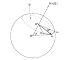
もっとも、式1Aを用いるには、図1Aに示すように、回転運動の軌跡上にある3点(H1、H2、H3)を確保して、それらの座標から図1Bに示すような差分ベクトル(ΔH2=H2−H1、ΔH3=H3−H2)を用意する必要がある。However, in order to use Formula 1A, as shown in FIG. 1A, three points (H 1 , H 2 , H 3 ) on the locus of the rotational motion are secured, and those coordinates are used as shown in FIG. 1B. It is necessary to prepare a difference vector (ΔH 2 = H 2 −H 1 , ΔH 3 = H 3 −H 2 ).
この算出方法を用いると、少なくとも3点が必要となり、高精度を確保するにはさらに、それら3点の磁気成分を取得する時間間隔を相対的に大きくせざるを得ない。このため式1Aによる角速度の算出は、移動体の姿勢変化(回転軸の変化)が小さい回転初期などでは有効であるが、急激な姿勢変化が生じる場合には追従し切れない。 When this calculation method is used, at least three points are required, and in order to ensure high accuracy, the time interval for acquiring the magnetic components of these three points must be relatively increased. For this reason, the calculation of the angular velocity by the equation 1A is effective in the initial stage of rotation where the change in the posture of the moving body (change in the rotation axis) is small, but cannot be followed when a sudden change in posture occurs.
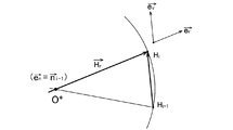
(2)そこで、式1Aに替えて、表現が異なる別の物理式である式2を用いて角速度ベクトルを算出することが考えられる。これによれば、図2Aおよび図2Bにも示すように、前述した3点を確保する必要が無く、任意の時刻(ti=t0+Δt・i、但しt0:測定開始時刻)における磁気ベクトルHiおよびその直前の磁気ベクトルHi−1を利用して、各時刻(ti)における瞬間的な角速度ベクトル(真性角速度ベクトルωth)を算出することができる。これにより、移動体の姿勢変化が急激な場合でも、殆ど遅れなく角速度を算出することが可能となり得る。(2) Therefore, it is conceivable to calculate the angular velocity
もっとも、式2、図2Aおよび図2Bからわかるように、上記の方法でωthを算出するには、瞬間的な回転中心(O*)から磁気ベクトルHiへ向かう動径ベクトルHrが、ΔHi以外に必要となる。この動径ベクトルHrを直接算出することは容易ではない。そこで本発明では、次のように場合分けしてωthを算出している。すなわち、移動体が回転する際の回転軸が固定的または安定的な場合(このような場合を適宜、「固定軸回転モード」という。)と、その回転軸が変動し得る場合(このような場合を適宜、「自由軸回転モード」という。)とに分けてωthを考えた。However, as can be seen from
なお、角運動量保存則により、回転軸は急激に変化しないから、回転モードの変更または移行は滑らかに行うことが可能である。そして、各回転モードによる演算開始時に適切な初期値が付与されることにより、回転モードが変更されても、高精度な演算結果を安定的または継続的に得ることができる。例えば、自由軸回転モードで角速度ベクトルωthを算出する際の初期値として、移行直前に固定軸回転モードで算出された角速度ベクトルωthを利用することが考えられる。Since the rotation axis does not change abruptly according to the law of conservation of angular momentum, the change or transition of the rotation mode can be performed smoothly. And by giving an appropriate initial value at the start of calculation in each rotation mode, even if the rotation mode is changed, a highly accurate calculation result can be obtained stably or continuously. For example, it is conceivable to use the angular velocity vector ω th calculated in the fixed axis rotation mode immediately before the transition as the initial value when calculating the angular velocity vector ω th in the free axis rotation mode.
[固定軸回転モード]
固定軸回転モードは、回転軸が安定的で実質的に変化しない場合である。この場合、式1Aおよび式1Bに基づく演算により、その回転軸または回転軸ベクトルnΔが特定される(回転軸ベクトル特定ステップ)。[Fixed shaft rotation mode]
The fixed axis rotation mode is when the rotation axis is stable and does not substantially change. In this case, the rotation axis or the rotation axis vector nΔ is specified by the calculation based on the expressions 1A and 1B (rotation axis vector specifying step).
真性角速度ベクトルωthを確定するには、残るその大きさを算出する必要がある。そこで、式3に示す仮想的な角速度ベクトル(仮性角速度ベクトルωpr)を考える。この角速度ベクトルωprは、最終的に求めたい角速度ベクトルωthと回転軸が異なるが、両者の大きさ(|ωpr|と|ωth|)の間には、式4に示すような関係が成立する。ここで式4中のαi は、図2Aに示すように、回転軸(回転軸ベクトルnΔ)と磁気ベクトルHiのなす角(∠O*OHi)である。In order to determine the intrinsic angular velocity vector ωth , it is necessary to calculate the remaining magnitude. Therefore, a virtual angular velocity vector (a pseudo angular velocity vector ω pr ) shown in
ちなみに、式4が成立することは次のことからわかる。磁気ベクトルHiの終点が回転運動する軌跡(平面S*の円周)上を微小時間Δtに移動する距離を考えると、|ωth|・Δt・|Hr|=|ωpr|・Δt・|Hi|が成立し得る。ここで図2Aに示す直角三角形OO*Hiから、|Hr|=|Hi|sinαi であるから、式4に示す|ωth|=|ωpr|/sinαi が導かれる。Incidentally, it can be seen from the following that equation 4 holds. Considering the distance that the end point of the magnetic vector H i moves on the trajectory (circumference of the plane S *) that rotates in a minute time Δt, | ω th | · Δt · | Hr | = | ω pr | · Δt · | H i | may hold. Here the right triangle OO * H i shown in FIG. 2A, | Hr | = | because it is sin .alpha i, shown in Equation 4 | | H i ω th | = | ω pr | / sinα i is derived.
なお、角αi は、式1Aおよび式1Bにより初期に算出された回転軸ベクトルnΔと磁気ベクトルHiの単位ベクトルhとのなす角でもあるから、両ベクトルの内積(h・nΔ)から求まるcosαi から、sinαi を容易に算出することができる(差角算出ステップ)。Note that the angle α i is also an angle formed by the rotation axis vector n Δ initially calculated by the equations 1A and 1B and the unit vector h of the magnetic vector H i , and therefore the inner product (h · n Δ ) of both vectors. from cos [alpha] i obtained from, it is possible to easily calculate the sin .alpha i (angle difference calculation step).
このように本発明では、先ずは、磁気ベクトルHi(第二磁気ベクトル)と、その近傍にある過去(または直前)の磁気ベクトルHi−1(第一磁気ベクトル)から求まる差分ベクトル(ΔHi=Hi−Hi−1)との外積を用いて、式3から角速度ベクトルωpr(仮性角速度ベクトル)を求める(仮性角速度ベクトル算出ステップ)。こうして求まったωprの大きさおよびsinαi と、式1Aおよび式1Bから求まるnΔとを用いて、角速度ベクトルωth(真性角速度ベクトル)は式5のように算出される(真性角速度ベクトル算出ステップ)。Thus, in the present invention, first, the difference vector (ΔH) obtained from the magnetic vector H i (second magnetic vector) and the past (or immediately preceding) magnetic vector H i-1 (first magnetic vector) in the vicinity thereof. An angular velocity vector ω pr (a pseudo angular velocity vector) is obtained from
[自由軸回転モード]
自由軸回転モードは、回転軸が変化する場合である。この場合も、任意のHi点(時刻ti)における真の角速度ベクトルωthを遅れなく算出するために、前述した式2を基本式とする点は同様である。もっとも、固定軸回転モードの場合と同様に動径ベクトルHrを直接的に求めることは困難であるため、自由軸回転モードの場合も、大きさと向き(角速度ベクトルni)に分けて角速度ベクトルωthを算出する。[Free axis rotation mode]
The free axis rotation mode is when the rotation axis changes. In this case as well, in order to calculate the true angular velocity vector ω th at an arbitrary H i point (time t i ) without delay, the point that the above-described
先ず、角速度ベクトルωthの大きさは、固定軸回転モードの場合と同様に、式3および式4から求まるωprおよびsinαi を用いて後述する式10のように|ωpr|/|sinαi|として算出される(仮性角速度ベクトル算出ステップ、差角算出ステップ)。First, the magnitude of the angular velocity vector ω th is equal to | ω pr | / | sin α as shown in Equation 10 described later using ω pr and sin α i obtained from
次に、角速度ベクトルωthの回転軸ベクトルniを、式2に基づいて求める。その前提として、式6に示す瞬間3軸直交座標系(回転座標系)を定義する。この座標系は、直前に特定されている(i−1)番目の回転軸ベクトルni−1 および角αi−1 は、次のi番目でも同じであると仮定して、基本ベクトルen=ni−1、このenとh(=Hi/|Hi|)に基づき正規化した基本ベクトルer、およびenとerの外積である基本ベクトルevにより構成した。この3軸直交座標系の様子を図2Aおよび図2Bに併記した。これら3つの基本ベクトルen、ev、erを用いると、式2にあるΔHiは、ev、en、er の各方向の成分をa、b、c(実係数)として式7のように表現される。Next, the rotation axis vector n i of the angular velocity vector ω th is obtained based on
ここで実際にαi=αi−1 ならc=0となるが、そうでないとき(αi ≠αi−1 )はc≠0となり、回転軸ベクトルni は回転軸ベクトルni−1(基本ベクトルen)よりも磁気ベクトルHi(またはh)の側へある角Δαi だけ傾いていることになる。この角Δαi は式8Aのように表現できるので、これらと式6に示した基本ベクトルen、ev、erとを用いて、式8Bに示す新たな3軸直交座標系を再定義する(図2C参照)。そうすると差分ベクトルΔHi は、式8Cのように表現される。また動径ベクトルHrは、大きさが|Hr|(=O*H)でその単位ベクトルが基本ベクトルer’と同じであるから、式8Dのように表現される。このように表現されたHrとΔHiを式2に代入してベクトル積を計算する。この際、右手系で考えるとer×en=−ev、er×ev=en、er×er=0(零ベクトル)であるから、式2は結局、式9Aのように整理され、角速度ベクトルωiが求まる。このωiを正規化すると、式9Bに示すように回転軸ベクトルniが得られる(回転軸ベクトル特定ステップ)。Here, if α i = α i−1, c = 0, but if not (α i ≠ α i−1 ), c ≠ 0, and the rotation axis vector n i is the rotation axis vector n i−1. It is inclined by an angle Δα i that is closer to the magnetic vector H i (or h) than the (basic vector e n ). This angle [Delta] [alpha] i can be expressed as equation 8A, the basic vector shown in these and Equation 6 e n, e v, by using the e r, redefine a new three-axis orthogonal coordinate system shown in Equation 8B (See FIG. 2C). Then, the difference vector ΔH i is expressed as in Expression 8C. Further, the radial vector Hr is expressed as Expression 8D because its magnitude is | Hr | (= O * H) and its unit vector is the same as the basic vector er ′. Thus the the represented Hr and [Delta] H i are substituted into
この回転軸ベクトルniと前述した角速度ベクトルの大きさ|ωpr|を用いて、角速度ベクトルωthは式10に示すようにωth=(|ωpr|/sinαi )・niとして算出される(真性角速度ベクトル算出ステップ)。Using this rotation axis vector n i and the above-described angular velocity vector magnitude | ω pr |, the angular velocity vector ω th is calculated as ω th = (| ω pr | / sin α i ) · n i as shown in Equation 10. (True angular velocity vector calculation step).
なお、niは次のni+1を求める際の基本ベクトルenとしてフィードバックされる(式6参照)。初期値は、静止状態から回転状態に移行する時または他の回転モードから移行する時のn1である。詳細は後述するが、そのn1は、例えば、ΔH0とΔH1の外積に基づき計算される(式1A参照)。また、加速度センサーと一体で静止状態の三次元方位(角)が計算済みであれば、その変化量から回転速度n1を計算することもできる。固定軸回転モードから自由軸回転モードへ移行した直後にわずかな誤差を生じるとしても、上述した演算を繰り返すことにより、その結果は精確なniへ極短時間内に収束する。Incidentally, n i is fed back as a basic vector e n for obtaining the next n i + 1 (see equation 6). The initial value is n 1 when shifting from the stationary state to the rotating state or when shifting from another rotation mode. Although details will be described later, the n 1 is calculated based on, for example, the outer product of ΔH 0 and ΔH 1 (see Formula 1A). In addition, if the three-dimensional azimuth (angle) in a stationary state is calculated with the acceleration sensor, the rotational speed n 1 can be calculated from the amount of change. Even cause slight errors immediately after transition to the free shaft rotation mode from the fixed axis rotation mode, by repeating the operation described above, the result converges on an extremely short time in the precise n i.
ちなみに、式7で用いた係数a、b、cは、差分ベクトルΔHiと各基本ベクトルen、ev、erとの内積計算により方向余弦として順次求めることができる。つまりa=ΔHi・ev、b=ΔHi・en、c=ΔHi・erとして求まる。Incidentally, the coefficient a, b, c used in equation 7 can be found sequentially as the direction cosines each basic vector and the difference vector ΔH i e n, e v, the inner product calculation with e r. That is, a = ΔH i · e v , b = ΔH i · e n , and c = ΔH i · e r .
[モード判定]
(1)基本判定
移動体の回転運動が、上述した固定軸回転モードにあるか、自由軸回転モードにあるかは、例えば、式1Aおよび式1Bから求まる上述した回転軸ベクトルnΔとΔHiとにより、式11から算出されるモード判定値Jを用いて判定可能である。このJは、nΔとΔHiのなす角をγとすると、cosγとなり、0〜1の範囲で変化し得る。[Mode judgment]
(1) Basic determination Whether the rotational motion of the moving body is in the fixed axis rotation mode or the free axis rotation mode described above is determined from, for example, the above-described rotation axis vectors n Δ and ΔH i obtained from Equation 1A and Equation 1B. Thus, the determination can be made using the mode determination value J calculated from Expression 11. The J, when the the angle n delta and [Delta] H i gamma, cos, and the may vary in the range of 0-1.
このJが0近傍にあるとき、γは90°近傍となり、移動体が安定した軸回りに回転運動する固定軸回転モードとなり、回転軸ベクトルnとしてnΔが継承される(一回転軸ベクトル特定ステップ)。そしてこの固定軸回転モードでは、式5により真の角速度ベクトルωthが算出される(真性角速度ベクトル算出ステップ)。When J is in the vicinity of 0, γ is in the vicinity of 90 °, and the fixed body rotation mode in which the moving body rotates around the stable axis is entered, and n Δ is inherited as the rotation axis vector n (one rotation axis vector specification) Step). In this fixed shaft rotation mode, the true angular velocity vector ω th is calculated by Equation 5 (true angular velocity vector calculating step).
逆に、Jが所定の閾値以上または閾値超である場合、移動体が変化する軸回りで回転運動する自由軸回転モードとなり、式8Aまたは式9Aにより算出されるniにより回転軸ベクトルnが順次更新される。この自由軸回転モードでは、式10により真の角速度ベクトルωthが算出される(真性角速度ベクトル算出ステップ)。Conversely, if J is more or threshold than a predetermined threshold value, it becomes free shaft rotation mode for rotating motion around the axis moving body is changed, the rotation axis vector n by n i calculated by the equation 8A or Formula 9A It is updated sequentially. In this free axis rotation mode, the true angular velocity vector ω th is calculated by Equation 10 (true angular velocity vector calculating step).
従って、本発明に係る回転軸ベクトル特定ステップは、移動体が特定の回転軸まわりに回転運動をする固定軸回転モードと、移動体が回転軸を変化させつつ回転運動する自由軸回転モードとを判定するモード判定ステップを備えると好適である。 Accordingly, the rotation axis vector specifying step according to the present invention includes a fixed axis rotation mode in which the moving body rotates around a specific rotation axis, and a free axis rotation mode in which the moving body rotates while changing the rotation axis. It is preferable that a mode determining step for determining is provided.
そして本発明に係る回転軸ベクトル特定ステップは、モード判定ステップにより固定軸回転モードと判定されたときに回転軸ベクトルnΔ を回転軸ベクトルnとし、モード判定ステップにより自由軸回転モードと判定されたときに逐次算出される回転軸ベクトルniを回転軸ベクトルnとして更新するステップであると好適である。The rotation axis vector specific steps according to the present invention, the rotation axis vector n delta when it is determined that the fixed shaft rotation mode by the mode determination step as the rotation axis vector n, is determined to free shaft rotation mode by the mode determination step It is preferable that the rotation axis vector n i that is sometimes calculated is updated as the rotation axis vector n.
(2)待機判定
移動体が静止状態から回転状態に移行したり、固定軸回転モード中に移動体の回転変化が急激になったり、逆に自由軸回転モード中に移動体の回転変化が緩慢になったりする場合、モード判定値J(式11参照)による判定結果が、移動体の回転状態を的確に反映していない場合が生じ得る。具体的にいうと、例えば、固定軸回転モード中に、移動体の回転半径(曲率半径)が急減すると、式1Aおよび式1Bにより求まる回転軸ベクトルΔnも微小となり、相対的に誤差の影響を大きく受けるようになる。その結果、固定軸回転モードを維持すればよい状況であるにも拘わらず、Jの数値自体は自由軸回転モードを示すようなことが起こり得る。但し、回転する移動体に作用する角運動量保存則を考慮すると、固定軸回転モードと自由軸回転モードが極短時間に頻繁に入れ替わることは考えられず、Jに基づくモード判定が不安定になるのは過渡的または一時的であると考えられる。(2) Standby determination The moving body shifts from the stationary state to the rotating state, the rotating change of the moving body becomes abrupt during the fixed axis rotation mode, or conversely, the rotating change of the moving body becomes slow during the free axis rotation mode. In some cases, the determination result by the mode determination value J (see Expression 11) may not accurately reflect the rotation state of the moving body. More specifically, for example, if the rotational radius (curvature radius) of the moving body rapidly decreases during the fixed axis rotation mode, the rotational axis vector Δn obtained by the equations 1A and 1B also becomes minute, and the influence of errors is relatively affected. I will be greatly received. As a result, it is possible that the numerical value of J itself indicates the free axis rotation mode although the fixed axis rotation mode only needs to be maintained. However, considering the angular momentum conservation law acting on the rotating moving body, the fixed axis rotation mode and the free axis rotation mode cannot be frequently switched in an extremely short time, and the mode determination based on J becomes unstable. Is considered transient or temporary.
そこで本発明に係る回転軸ベクトル特定ステップは、モード判定値(J)が所定時間(判定時間)継続して所定範囲内となる場合になされると好ましい。つまり本発明に係る回転軸ベクトル特定ステップは、第一差分ベクトル(ΔHi)と第二差分ベクトル(ΔHi−1=Hi−1−Hi−2)の外積(ΔHi−1×ΔHi)から求まる回転軸ベクトル(nΔ)と、第一差分ベクトル(ΔHi)とを用いて算出されたモード判定値に基づき、選択すべき回転モードを判定するモード判定ステップを備え、さらに、このモード判定ステップが、所定時間継続して(待機して)モード判定値が所定範囲内となるときに回転モードの変更を判定する待機判定ステップを備えるとより好適である。Therefore, the rotation axis vector specifying step according to the present invention is preferably performed when the mode determination value (J) continues within a predetermined range for a predetermined time (determination time). That is, the rotation axis vector specifying step according to the present invention includes the outer product (ΔH i-1 × ΔH) of the first difference vector (ΔH i ) and the second difference vector (ΔH i-1 = H i-1 -H i-2 ). a mode determination step of determining a rotation mode to be selected based on a mode determination value calculated using the rotation axis vector (n Δ ) obtained from i ) and the first difference vector (ΔH i ); It is more preferable that this mode determination step includes a standby determination step of determining a change in the rotation mode when the mode determination value is within a predetermined range for a predetermined time (waiting).
(3)凍結判定
本発明では、移動体に設定した座標系に基づいて基準磁気を連続的に測定して得られた三次元の磁気成分からなる磁気ベクトルの変化分(差分ベクトル)を微小時間毎に逐次算出して、回転情報の演算を行っている。このため、移動体の回転軸が、その基準磁気の軸(以下「基準軸」または「特異軸」という。基準磁気が地磁気の場合なら地軸が基準軸に相当する。)に近接すると、検出される磁気ベクトルの回転方向成分(差分ベクトル)が相対的に非常に小さくなる。このようなときに回転軸ベクトルの算出を行うと、誤差が生じ易くなる。もっとも、このような誤差を生じ易い特異領域は、全体の僅か数%程度である。また、移動体の回転運動が自由軸回転モードにある場合、その回転軸が一時的(または瞬間的)に特異領域に属する(基準軸に近接する)ことがあっても、通常、その回転軸は極短時間後にその特異領域から脱出する。(3) Freezing determination In the present invention, a change amount (difference vector) of a magnetic vector composed of a three-dimensional magnetic component obtained by continuously measuring reference magnetism based on a coordinate system set for a moving body is measured for a short time. The rotation information is calculated by sequentially calculating each time. For this reason, the rotation axis of the moving body is detected when it approaches the axis of the reference magnetism (hereinafter referred to as “reference axis” or “singular axis”. If the reference magnetism is geomagnetism, the earth axis corresponds to the reference axis). The rotational direction component (difference vector) of the magnetic vector is relatively very small. If the rotation axis vector is calculated in such a case, an error is likely to occur. However, only a few percent of the entire unique region is likely to cause such an error. Also, when the rotary motion of the moving body is in the free axis rotation mode, even if the rotation axis temporarily (or instantaneously) belongs to the singular region (close to the reference axis), usually the rotation axis Escapes from its unique region after a very short time.
そこで、あらゆる回転領域で移動体の回転情報を安定的に演算するために、算出された回転軸ベクトルと基準軸(基準磁気ベクトルHs)のなす角(δ)が所定範囲内にあるとき、回転モードの変更、さらには回転軸ベクトルの置換を凍結すると好適である。すなわち、本発明に係る回転軸ベクトル特定ステップ(モード判定ステップ)は、さらに、基準磁気を指標する基準磁気ベクトル(Hs)と回転軸ベクトルの近接具合を指標する近接指標値が所定の第一範囲内となるときに、回転モードの変更を凍結するモード判定凍結ステップを備えると好適である。また凍結判定ステップは、さらに、その近接指標値が第一範囲に含まれる第二範囲内となるときに、回転軸ベクトルの更新を凍結する回転軸凍結ステップを含むとより好適である。なお、近接指標値は、例えば、上述した角δでもよいし、回転軸ベクトルと基準磁気ベクトルの内積値等でもよい。 Therefore, in order to stably calculate the rotation information of the moving body in any rotation region, the rotation is performed when the angle (δ) formed by the calculated rotation axis vector and the reference axis (reference magnetic vector Hs) is within a predetermined range. It is preferable to freeze the mode change, and further the rotation axis vector replacement. That is, the rotation axis vector specifying step (mode determination step) according to the present invention further includes a reference magnetic vector (Hs) indicating the reference magnetism and a proximity index value indicating the proximity of the rotation axis vector within a predetermined first range. It is preferable to provide a mode determination freezing step for freezing the change of the rotation mode. More preferably, the freezing determination step further includes a rotating shaft freezing step for freezing the updating of the rotating shaft vector when the proximity index value falls within the second range included in the first range. The proximity index value may be, for example, the angle δ described above, or the inner product value of the rotation axis vector and the reference magnetic vector.
このような凍結を行う特異領域の設定は磁気センサーの性能に応じて適宜設定すればよい。例えば、δ<10°〜20°(第一範囲)のときは回転モードの変更を凍結し、さらにδ<6°〜10°(第二範囲)のときはそれ以前に算出した回転軸ベクトルを継承して回転軸ベクトルの更新を凍結すると好ましい。 What is necessary is just to set suitably the specific area | region which performs such freezing according to the performance of a magnetic sensor. For example, when δ <10 ° to 20 ° (first range), the rotation mode change is frozen, and when δ <6 ° to 10 ° (second range), the rotation axis vector calculated before that is used. It is preferable to inherit and freeze the update of the rotation axis vector.
[軌道軸回転モード]
(1)本発明者がさらに研究したところ、移動体の回転モードとして、上述した固定軸回転モードと自由軸回転モード以外に、移動体が回転軸を変化させつつも、特定の姿勢を保持してほぼ一定の軌道軸周りに回転運動する軌道軸回転モードがさらに存在することがわかった。[Orbital axis rotation mode]
(1) As a result of further research by the present inventor, as a rotation mode of the moving body, in addition to the fixed axis rotation mode and the free axis rotation mode described above, the moving body maintains a specific posture while changing the rotation axis. In addition, it was found that there are more orbital axis rotation modes that rotate around an almost constant orbital axis.
磁気ベクトル空間とは別に、回転軸ベクトル空間を三軸直交座標系で考えた場合、回転軸ベクトル(n)の終点N(nX、ny、nz)は原点を中心とした半径1の球面(単位球)上を移動する。この終点Nの軌跡は回転モード毎に特有なものとなるが、軌道軸回転モードの軌跡は、固定軸回転モードや自由軸回転モードとは異なるものとなった。具体的にいうと、固定軸回転モードに係る軌跡は単位球上の一点となり、自由軸回転モードに係る軌跡は単位球上の任意の曲線となるが、軌道軸回転モードに係る軌跡はそれらと異なり、単位球上の円または楕円(特定の投影面で観れば直線)となった。In addition to the magnetic vector space, when the rotation axis vector space is considered in a three-axis orthogonal coordinate system, the end point N (n x , n y , n z ) of the rotation axis vector (n) is a
このような軌道軸回転モードは、移動体が自由に移動できず、その回転が特定の軌道軸周りに拘束されている場合に生じる。このため、前述した自由軸回転モードによる演算のみでは、軌道軸回転モードにある移動体の精確な回転情報を安定的に得ることはできない。但し、軌道軸回転モードは、自由軸回転モードの特異モードと考えることができる。このため、軌道軸回転モードに係る回転軸ベクトルは、自由軸回転モードで得られた回転軸ベクトル(ni)を適切に修正した修正回転軸ベクトル(ni’)として求めることが可能である。そして、ni’をniと置換することにより、上述した自由軸回転モードに係るアルゴリズムを軌道軸回転モードでも利用することが可能となる。ni’の算出方法(niの修正方法)は、具体的にいうと次の通りである。Such a track axis rotation mode occurs when the moving body cannot freely move and its rotation is constrained around a specific track axis. For this reason, accurate rotation information of the moving body in the orbital axis rotation mode cannot be obtained stably only by the calculation in the above-described free axis rotation mode. However, the orbital axis rotation mode can be considered as a singular mode of the free axis rotation mode. Therefore, the rotation axis vector related to the orbital axis rotation mode can be obtained as a corrected rotation axis vector (n i ′) obtained by appropriately correcting the rotation axis vector (n i ) obtained in the free axis rotation mode. . Then, by replacing the n i 'and n i, it becomes possible to use an algorithm orbital axis rotation mode of the free shaft rotation mode described above. More specifically, the calculation method of n i ′ (the correction method of n i ) is as follows.
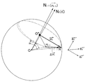
(2)軌道軸回転モードの場合、図3を参照するとわかるように、軌道軸(Nob)に沿って正規化された軌道軸ベクトル(nob)は、隣接する各時刻における回転軸ベクトル(ni、ni−1、ni−2)の変化分を示す軸変化ベクトル(Δni、Δni−1)を用いて、式21Aにより求まる。そして、その軌道軸と軸変化ベクトル(Δni)のなす角である軌道角(φob)およびその指標値(cosφob、sinφob)が式21Bから求まる。これらを用いて、ni’は式22のように求めることができる。こうして得られたni’を新たなniとする。軌道軸回転モードが継続していれば、そのniを用いて次のni+1(暫定回転軸ベクトル)を自由軸回転モードで算出する。このni+1を用いて式21Aにより算出したni+1’を、再度新たなniとする。このような操作を、軌道軸回転モードが継続する限り繰り返す。(2) When the orbital axis rotation mode, as seen with reference to FIG. 3, the track axis (N ob) is normalized along the trajectory axis vector (n ob), the rotation axis vector at each time adjacent ( Using an axis change vector (Δn i , Δn i-1 ) indicating the amount of change in n i , n i-1 , n i-2 ), the equation 21A is used. Then, the orbital angle (φ ob ) that is an angle formed by the orbital axis and the axis change vector (Δn i ) and the index values (cosφ ob , sinφ ob ) are obtained from the equation 21B. Using these, n i ′ can be obtained as shown in Equation 22. A n i 'obtained in this way as a new n i. If continued orbital axis rotation mode, and calculates a free shaft rotation mode the next n i + 1 (provisional rotation axis vector) using the n i. The n i + 1 n i + 1 calculated by Formula 21A using 'as a new re n i. Such an operation is repeated as long as the orbital axis rotation mode continues.
(3)なお、軌道軸回転モードか否かの判定は、例えば、軌道軸ベクトル(nob)と軸変化ベクトル(Δni)を用いて式23により算出される指標値(K)が、特定範囲内にあるか否か(より具体的にいえば0近傍か否か)により判断し得る。(3) The determination of whether or not the mode is the orbital axis rotation mode is performed by, for example, specifying the index value (K) calculated by the equation 23 using the orbital axis vector ( nob ) and the axis change vector (Δn i ). The determination can be made based on whether or not it is within the range (more specifically, whether or not it is near 0).
以上を踏まえて、本発明に係る回転軸ベクトル特定ステップは、さらに、移動体が回転軸を変化させつつ特定の姿勢を保持して略一定の軌道軸の周りに回転運動する軌道軸回転モードにあるとき、自由軸回転モードで得られた少なくとも3つの時刻(ti、ti−1、ti−2)における各回転軸ベクトル(ni、ni−1、ni−2)の隣接間の差分ベクトルである第一軸変化ベクトル(Δni=ni−ni−1)と第二軸変化ベクトル(Δni−1=ni−1−ni−2)の外積(Δni−1×Δni)により軌道軸を指標する軌道軸ベクトル(nob)を特定する軌道軸ベクトル特定ステップと、軌道軸ベクトル(nob)と回転軸ベクトル(ni)のなす角である軌道角(φob)または軌道角を指標する軌道角指標値を算出する軌道角算出ステップと、軌道角に基づいて自由軸回転モードで得られた回転軸ベクトル(ni)を修正した修正回転軸ベクトル(ni’)を軌道軸回転モードにおける新たな回転軸ベクトル(ni)とする回転軸ベクトル修正ステップと、を有すると好適である。Based on the above, the rotation axis vector specifying step according to the present invention is further performed in the orbital axis rotation mode in which the moving body maintains a specific attitude while changing the rotation axis and rotates around a substantially constant orbital axis. In some cases, adjacent to each rotation axis vector (n i , n i-1 , n i-2 ) at at least three times (t i , t i-1 , t i-2 ) obtained in the free axis rotation mode. The cross product (Δn i ) of the first axis change vector (Δn i = n i −n i−1 ) and the second axis change vector (Δn i−1 = n i−1 −n i− 2 ), which is a difference vector between them. −1 × Δn i ), a trajectory axis vector specifying step for specifying the trajectory axis vector (n obs ) that indicates the trajectory axis, and a trajectory that is an angle formed by the trajectory axis vector (n obs ) and the rotation axis vector (n i ). angle (φ ob) or a track indicative of the orbital angular And the track angle calculation step of calculating an index value, a new rotation axis vector obtained in the free shaft rotation mode on the basis of the orbital angular (n i) corrected rotation axis vector that fixes the (n i ') in the track axis rotation mode It is preferable to have a rotation axis vector correction step that sets a rotation axis vector (n i ) as a new value.
この場合、本発明に係るモード判定ステップは、固定軸回転モードと自由軸回転モードの判定以外に、上述した指標値(K)等を用いて軌道軸回転モードの判定も行うステップであると好ましい。そして、その判定結果に応じて、回転軸ベクトル(n)を算出する回転モードの選択(継続または変更)が適切になされると好ましい。 In this case, it is preferable that the mode determination step according to the present invention is a step of determining the orbital axis rotation mode using the index value (K) described above, in addition to the determination of the fixed axis rotation mode and the free axis rotation mode. . Then, it is preferable that selection (continuation or change) of the rotation mode for calculating the rotation axis vector (n) is appropriately made according to the determination result.
[反転モード]
(1)本発明では、移動体の回転運動が角運動量保存則(または慣性の法則)により急激な変化をしないことを前提として、適切な演算を逐次繰り返すことにより移動体の回転情報を精確に求めている。しかし、軌道軸回転モードの場合と同様に、人為的な操作等により移動体は急激な回転運動や特異な回転運動をし得る。その一例として、特定の回転軸まわりに回転している移動体の回転方向を、急激に反転(逆転)させたり、その反転を繰り返すような振動をさせたりする場合がある。なお、本明細書では、その振動も含めて単に反転という。[Reverse mode]
(1) In the present invention, on the assumption that the rotational motion of the moving body does not change abruptly by the law of conservation of angular momentum (or the law of inertia), the rotation information of the moving body is accurately obtained by sequentially repeating appropriate calculations. Seeking. However, as in the case of the orbital axis rotation mode, the moving body can perform a sudden rotation motion or a specific rotation motion by an artificial operation or the like. As an example, there is a case where the rotation direction of a moving body rotating around a specific rotation axis is suddenly reversed (reversed) or vibrations are repeated. In this specification, it is simply called reversal including the vibration.
このような反転運動がなされると、回転軸ベクトル(ni)の向き(正負)が急激に変化する。このため、上述した逐次演算のみでは、その急激な変化に追従しきれず、移動体の回転情報を適時に精確に算出できないおそれが生じ得る。そこで、移動体に反転が生じた反転モードか否かを判定し、反転モードのときは、回転軸ベクトル(ni)の向き(正負)を反転させた反転回転軸ベクトル(−ni)を、新たな回転軸ベクトル(ni)として上述した演算を繰り返すことにより、移動体の回転運動に追従しつつ、その回転運動を精確に求めることができる。When such a reversal motion is made, the direction (positive / negative) of the rotation axis vector (n i ) changes abruptly. For this reason, with only the above-described sequential calculation, it is not possible to follow the sudden change, and there is a possibility that the rotation information of the moving body cannot be accurately calculated in a timely manner. Therefore, it is determined whether inversion mode or not the inversion occurs in the mobile, when the reverse mode, inverting the rotation axis vector obtained by inverting the direction (positive or negative) of the rotary axis vector (n i) of (-n i) By repeating the above-described calculation as a new rotational axis vector (n i ), the rotational motion can be accurately obtained while following the rotational motion of the moving body.
(2)反転モードの判定は、例えば、次のようにして行うことができる。移動体の回転運動は連続的であるから、回転軸まわりの角速度が正から負または負から正へ変化する点(反転ポイント)で、移動体の角速度ω(具体的には仮性角速度ベクトル(ωpr)または真性角速度ベクトル(ωth))の大きさはゼロとなる。そこで、移動体の角速度ωを与える式2、式3または式9Aを考慮して、角速度の大きさ|ω|がゼロとなる前後で、二つの磁気ベクトル(Hi)の差分ベクトル(ΔHi=Hi−Hi−1)を求める。その一方は|ω|が0に近づく側(|ω|が減少する側)の前差分ベクトル(ΔHb)であり、他方は|ω|が0から遠ざかる側(|ω|が増加する側)の後差分ベクトル(ΔHa)である。(2) The determination of the inversion mode can be performed as follows, for example. Since the rotational motion of the moving body is continuous, the angular velocity ω (specifically, the pseudo angular velocity vector (ω) is the point at which the angular velocity around the rotation axis changes from positive to negative or from negative to positive (inversion point). pr ) or the intrinsic angular velocity vector (ω th )) is zero. Therefore, in consideration of
これら両差分ベクトルを単位ベクトル化(Δha=ΔHa/|ΔHa|、Δhb=ΔHb/|ΔHb|)した後にその内積(P=Δhb・Δha)を求める。その内積値が負であれば、|ω|がゼロとなる前後で求めた両差分ベクトルは、向き(符号)がほぼ反転していると判断できる。つまり、反転ポイントの前後で移動体には反転運動が生じていると判断できる。逆にその内積値が正であれば、両差分ベクトルは同符号であるから、反転ポイントの前後で移動体に反転運動は生じていないと判断できる。なお、指標値Pは式24に示すように算出してもよい。この場合、反転時に−1、非反転時に1となるため、本発明に係る演算アルゴリズム(回転軸ベクトル特定ステップ)へ組み込み易い。 After these two difference vectors are converted into unit vectors (Δha = ΔHa / | ΔHa |, Δhb = ΔHb / | ΔHb |), the inner product (P = Δhb · Δha) is obtained. If the inner product value is negative, it can be determined that the direction (sign) of the difference vectors obtained before and after | ω | becomes zero is almost reversed. That is, it can be determined that a reversal motion has occurred in the moving body before and after the reversal point. On the other hand, if the inner product value is positive, both difference vectors have the same sign, so that it can be determined that no reversal motion has occurred in the moving body before and after the reversal point. The index value P may be calculated as shown in Expression 24. In this case, since it is -1 at the time of inversion and 1 at the time of non-inversion, it is easy to incorporate into the calculation algorithm (rotation axis vector specifying step) according to the present invention.
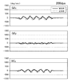
なお、|ω|が0となる極近傍では、差分ベクトルの符号(正負)が微妙に変化(振動)することがあり、反転モードが誤判定されるおそれがある。そこで、|ω|が0となる極近傍(−ε<|ω|<+ε、ε:微小値)を除く範囲で算出した差分ベクトルを保存(記憶)し、それらを上述した前差分ベクトル(ΔHb)および後差分ベクトル(ΔHa)として採用するとよい。この様子を図4に示した。 Note that in the very vicinity where | ω | is 0, the sign (positive / negative) of the difference vector may slightly change (vibrate), and the inversion mode may be erroneously determined. Therefore, the difference vector calculated in a range excluding the extreme vicinity where −ω | becomes 0 (−ε <| ω | <+ ε, ε: minute value) is stored (stored), and the difference vector is stored in the previous difference vector (ΔHb). ) And the post-difference vector (ΔHa). This situation is shown in FIG.
このように本発明に係る回転軸ベクトル特定ステップは、仮性角速度ベクトル(ωpr)または真性角速度ベクトル(ωth)の大きさがゼロとなる前後のそれぞれで磁気ベクトルの差分ベクトルとして求められた前差分ベクトル(ΔHb)と後差分ベクトル(ΔHa)の向きが反転するとき、回転軸ベクトル(ni)の向きを反転させた反転回転軸ベクトル(−ni)を新たな回転軸ベクトル(ni)とする回転軸ベクトル反転ステップをさらに有すると好適である。そして本発明に係るモード判定ステップは、前述した各回転モードの判定と併行して反転モードの判定も行うと好ましい。なお、本明細書でいう「反転」とは、反転ポイントの前後の差分ベクトル(ΔHa、ΔHb)の向きが実質的に反対方向であれば、両差分ベクトルのなす角が180°でなくてもよい。つまり、本明細書でいう「反転」は、前述した指標値Pを用いた判定方法からもわかるように、両差分ベクトルのなす角が鈍角となればよい。As described above, the rotational axis vector specifying step according to the present invention is performed before the pseudo angular velocity vector (ω pr ) or the intrinsic angular velocity vector (ω th ) is obtained as a magnetic vector difference vector before and after the magnitude becomes zero. When the directions of the difference vector (ΔHb) and the subsequent difference vector (ΔHa) are inverted, the inverted rotation axis vector (−n i ) obtained by inverting the direction of the rotation axis vector (n i ) is replaced with a new rotation axis vector (n i). It is preferable to further include a rotation axis vector reversing step. In the mode determination step according to the present invention, it is preferable that the reversal mode is determined in parallel with the determination of each rotation mode. In this specification, “inversion” means that the direction of the difference vectors (ΔHa, ΔHb) before and after the inversion point is substantially opposite, even if the angle formed by both difference vectors is not 180 °. Good. That is, “inversion” as used in the present specification only requires that the angle formed by both difference vectors is an obtuse angle, as can be seen from the determination method using the index value P described above.
[初期値]
移動体の回転情報(特に角速度)を追従性よく精確に求めるには、演算方法のみならず、初期値(特に回転軸ベクトルniの初期値n0)が重要となる。移動体が回転状態にあれば、回転モードが変更になっても、継承できる初期値があるため、問題はあまり生じない。[initial value]
To determine the rotational information of the moving body (in particular the angular velocity) trackability good precisely includes not calculation method only, the initial value (in particular the initial value n 0 of the rotation axis vector n i) is important. If the moving body is in a rotating state, even if the rotation mode is changed, there is an initial value that can be inherited, so there is not much problem.
しかし、回転軸ベクトルも角速度ベクトルも実質的にゼロとなっている静止状態または準静止状態(非常に緩やかに移動している状態等)から回転状態へ移行して各回転モードで演算を開始(または再開)する場合、継承すべき初期値がないため、精確な演算結果を迅速に得るには適切な初期値を与えることが必要となる。 However, the calculation is started in each rotation mode by shifting from a stationary state or a quasi-stationary state (such as a state of moving very slowly) in which both the rotation axis vector and the angular velocity vector are substantially zero. In the case of resuming), since there is no initial value to be inherited, it is necessary to provide an appropriate initial value in order to obtain an accurate calculation result quickly.
(1)移行期
移動体は、通常、基準磁気(地磁気)を三次元的に測定可能な磁気センサーのみならず、基準加速度(重力加速度)を三次元的に測定可能な加速度センサーも備え、それらセンサーにより得られた各成分(合計6成分)を処理して自身の姿勢(方位または向き)を把握する公知な三次元方位計算プログラムを備える。このようなシステムを本明細書では、適宜、「姿勢ジャイロスコープ」という。(1) Transition period The moving body is usually equipped with not only a magnetic sensor that can measure the reference magnetism (geomagnetism) in three dimensions but also an acceleration sensor that can measure the reference acceleration (gravity acceleration) in three dimensions. A known three-dimensional azimuth calculation program for processing each component (total of six components) obtained by the sensor to grasp its posture (azimuth or orientation) is provided. In the present specification, such a system is appropriately referred to as a “posture gyroscope”.
三次元方位計算プログラムを実行すると、各時刻における移動体の方位が求まる。その方位成分(三次元座標軸とのなす角度(θ、η、φ))を、時間微分、具体的には所定時間(Δt)の間に生じた各方位成分の変化量(回転変化量)をその時間(Δt)で除すことにより、任意の時刻における移動体の角速度ベクトルが求まり、ひいては回転軸ベクトルも求まる。こうして求まった角速度ベクトルまたは回転軸ベクトル(n0)を初期値として用いると、静止状態(特に断らない限り、準静止状態を含む。)から回転状態へ移行する移行期(過渡期)からでも、追従性のよい精確な演算が可能となる。When the three-dimensional azimuth calculation program is executed, the azimuth of the moving body at each time is obtained. The azimuth component (angle (θ, η, φ) made with the three-dimensional coordinate axis) is time-differentiated, specifically, the change amount (rotational change amount) of each azimuth component generated during a predetermined time (Δt). By dividing by the time (Δt), the angular velocity vector of the moving body at an arbitrary time can be obtained, and thus the rotation axis vector can also be obtained. When the angular velocity vector or the rotation axis vector (n 0 ) thus obtained is used as an initial value, even from the transition period (transition period) in which the stationary state (including the quasi-static state is included unless otherwise specified), Accurate calculation with good followability is possible.
ところで、姿勢ジャイロスコープは、通常、向きと大きさが安定している重力加速度を加速度センサーで検出し、その検出結果を磁気センサーによる地磁気の検出結果と併せて移動体の方位(姿勢)を算出している。ところが加速度センサーは、重力加速度のみならず、動加速度も検出する。このため移動体が静止状態から急激に回転運動を開始するような場合、姿勢ジャイロスコープから得られる初期値は、移動体に作用する大きな動加速度も加味した値となり、必ずしも正確ではない。つまり、動加速度が大きくなるほど、姿勢ジャイロスコープから求まる回転軸の誤差は大きくなる。なお、ここでいう動加速度(Gm)は、回転加速度(ra/a:角加速度、r:回転半径)と遠心加速度(rω2)の和であり、加速度センサーにより検出される加速度(G)は、その動加速度(Gm)と重力加速度(G0)の和となる。By the way, posture gyroscopes usually detect gravitational acceleration, which is stable in direction and size, with an acceleration sensor, and calculate the azimuth (posture) of the moving object together with the detection result of geomagnetism by the magnetic sensor. doing. However, the acceleration sensor detects not only gravitational acceleration but also dynamic acceleration. For this reason, when the moving body suddenly starts to rotate from a stationary state, the initial value obtained from the posture gyroscope is a value that takes into account the large dynamic acceleration acting on the moving body, and is not necessarily accurate. That is, as the dynamic acceleration increases, the rotation axis error obtained from the attitude gyroscope increases. The dynamic acceleration (G m ) here is the sum of rotational acceleration (ra / a: angular acceleration, r: rotational radius) and centrifugal acceleration (rω 2 ), and acceleration (G) detected by the acceleration sensor. Is the sum of the dynamic acceleration (G m ) and the gravitational acceleration (G 0 ).
一方、移動体が静止状態から急激に回転運動を開始する場合、磁気ベクトルも急激に変化し、十分に大きな差分ベクトルΔHが回転初期に得られる。十分に大きな二つの差分ベクトル(ΔH0、ΔH1)が得られれば、式1Aおよび式1Bから、正確な回転軸ベクトル(nΔ0)も求まる。この回転軸ベクトル(nΔ0)を、自由軸回転モードにおける初期値(n1)とすることにより、移行期以降の演算を正確に行うことが可能となる。なお、上述した初期値(n0、nΔ0)のいずれを採用するかは、例えば、移行期にお移動体の動加速度(Gm=ra+rω2)またはその指標値を、所定の閾値と比較することにより判定できる。On the other hand, when the moving body suddenly starts rotating from a stationary state, the magnetic vector also changes abruptly, and a sufficiently large difference vector ΔH is obtained at the initial stage of rotation. If two sufficiently large difference vectors (ΔH 0 , ΔH 1 ) are obtained, an accurate rotation axis vector (n Δ0 ) can also be obtained from Equations 1A and 1B. By using this rotation axis vector (n Δ0 ) as the initial value (n 1 ) in the free axis rotation mode, it becomes possible to accurately perform the calculation after the transition period. Note that which of the above-described initial values (n 0 , n Δ0 ) is used is, for example, comparing the moving acceleration (G m = ra + rω 2 ) of the moving object or its index value with a predetermined threshold value during the transition period. This can be determined.
そこで、移動体が静止状態または準静止状態から回転状態へ移行する移行期(動加速度が少なくとも所定の閾値を超える範囲にあるとき)のような、微小時間(Δt)内の磁気変化量(ΔH)が所定の微小範囲内にあるとき、本発明に係る回転軸ベクトル特定ステップは、さらに、第一時刻(ti)と第二時刻(ti−1)で測定した基準磁気と基準加速度の三次元測定値を三次元方位計算プログラムで処理して得た各時刻における三次元方位値に基づいて算出した回転状態以前の静的回転軸ベクトル(ns0)を、回転状態へ移行した時の前記回転軸ベクトルの初期値(n1)とする初期値設定ステップを有すると好適である。Therefore, the amount of magnetic change (ΔH) within a minute time (Δt) such as a transition period (when the dynamic acceleration is in a range exceeding at least a predetermined threshold) when the moving body shifts from a stationary state or a quasi-stationary state to a rotating state. ) Is within a predetermined minute range, the rotation axis vector specifying step according to the present invention further includes the reference magnetism and the reference acceleration measured at the first time (t i ) and the second time (t i-1 ). When the static rotation axis vector ( ns0 ) before the rotation state calculated based on the three-dimensional direction value at each time obtained by processing the three-dimensional measurement value with the three-dimensional direction calculation program is changed to the rotation state. It is preferable to have an initial value setting step for setting an initial value (n 1 ) of the rotation axis vector.
この初期値設定ステップは、さらに、微小時間(Δt)内の磁気変化量(ΔH)が所定の微小範囲内であると共に前記移動体の動加速度が少なくとも所定の閾値以上(所定範囲内)となるとき、第一差分ベクトル(ΔHi)と第二差分ベクトル(ΔHi−1)との外積(ΔHi−1×ΔHi)により算出される回転軸ベクトル(nΔ0)を、回転軸ベクトルの初期値(n1)とするステップを備えると好適である。In this initial value setting step, the magnetic change amount (ΔH) within a minute time (Δt) is within a predetermined minute range, and the dynamic acceleration of the moving body is at least a predetermined threshold value (within a predetermined range). Then, the rotation axis vector (n Δ0 ) calculated by the outer product (ΔH i-1 × ΔH i ) of the first difference vector (ΔH i ) and the second difference vector (ΔH i-1 ) is It is preferable to provide a step of setting an initial value (n 1 ).
(2)特異環境下/水平回転
既述したように、移動体の回転軸が基準磁気の軸(基準軸または特異軸)に近接すると、検出される磁気ベクトルひいては差分ベクトルの回転方向成分が小さくなる。このような状況は、瞬間的または一時的に回転運動している移動体の回転軸が基準軸に近接する場合の他、鉛直方向に延在する鉄筋(強磁性体)を有する建物内等で基準磁気が強磁性体によって垂直方向(鉛直方向)に偏向している環境下で移動体を略水平回転させる場合にも生じ得る。また基準磁気が地磁気である場合、地球の極点付近でも同様な状況が生じる。(2) Under Singular Environment / Horizontal Rotation As described above, when the rotation axis of the moving body is close to the axis of reference magnetism (reference axis or singular axis), the detected magnetic vector and thus the rotation direction component of the difference vector is small. Become. Such a situation may occur in a building having a reinforcing bar (ferromagnet) extending in the vertical direction, in addition to the case where the rotational axis of a moving body that is rotating momentarily or temporarily is close to the reference axis. This can also occur when the moving body is rotated substantially horizontally in an environment where the reference magnetism is deflected in the vertical direction (vertical direction) by the ferromagnetic body. When the reference magnetism is geomagnetism, a similar situation occurs near the poles of the earth.
このような特異環境下で移動体を略水平回転させるとき、上述した姿勢ジャイロスコープから算出される回転軸ベクトル(n0またはns0)や二つの差分ベクトルの外積(ΔH0×ΔH1)から算出される回転軸ベクトル(nΔ0)は、垂直軸(鉛直軸)方向以外の成分を含み易く、必ずしも移動体の回転状態に適した初期値とはならない。このような場合、垂直軸を回転軸として固定軸回転モードにより演算を行う(開始する)ことにより、回転初期から精確な演算結果を得ることが可能となる。When the moving body is rotated substantially horizontally under such a singular environment, from the rotation axis vector (n 0 or n s0 ) calculated from the attitude gyroscope described above and the outer product (ΔH 0 × ΔH 1 ) of two difference vectors. The calculated rotation axis vector (n Δ0 ) is likely to include components other than the vertical axis (vertical axis) direction, and is not necessarily an initial value suitable for the rotational state of the moving body. In such a case, an accurate calculation result can be obtained from the initial stage of rotation by performing (starting) the calculation in the fixed axis rotation mode with the vertical axis as the rotation axis.
なお、基準加速度(重力)は特異環境下による影響を基本的に受けない。このため特異環境下にあるか否かは、その環境下で磁気センサーにより測定される基準磁気(地磁気)と加速度センサーにより測定される基準加速度(重力)とのなす角(ζ)またはその指標値が所定範囲内(例えば、ζ<20°)にあるか否かにより判断できる。また、移動体が略水平回転をしているか否かは、例えば、式25に示すように、重力加速度ベクトル(G)と動加速度ベクトル(Gm)の内積値からなる水平指標値Qが所定範囲内(ゼロ近傍)にあるか否かにより判断できる。なお、移動体が完全な水平回転をしているとき、動加速度(Gm)は遠心加速度(rω2)のみとなり、水平指標値Q=0となる。Note that the reference acceleration (gravity) is basically not affected by the singular environment. For this reason, whether or not it is in a specific environment is determined by the angle (ζ) between the reference magnetism (geomagnetic) measured by the magnetic sensor and the reference acceleration (gravity) measured by the acceleration sensor in that environment or its index value Is within a predetermined range (for example, ζ <20 °). Whether or not the moving body is rotating substantially horizontally is determined by, for example, a horizontal index value Q consisting of the inner product value of the gravitational acceleration vector (G) and the dynamic acceleration vector (G m ) as shown in Expression 25. It can be judged by whether or not it is within the range (around zero). Note that when the moving body rotates completely horizontally, the dynamic acceleration (G m ) is only the centrifugal acceleration (rω 2 ), and the horizontal index value Q = 0.
ちなみに、特異環境下であるか否かを問わず、移動体の略水平回転は頻繁になされる。そこで、略水平回転であることが水平指標値Q等により判定された場合、垂直軸を回転軸とした固定軸回転モードによる演算を自動的に行うようにしてもよい。 Incidentally, regardless of whether or not it is under a specific environment, the moving body is rotated substantially horizontally. Therefore, when it is determined from the horizontal index value Q or the like that the rotation is substantially horizontal, the calculation in the fixed axis rotation mode with the vertical axis as the rotation axis may be automatically performed.
そこで本発明に係る回転軸ベクトル特定ステップは、移動体が静止状態または準静止状態から回転状態へ移行する移行期等で、重力加速度ベクトルと動加速度ベクトルのなす角またはその指標値が所定範囲内となるとき、重力加速度ベクトルを指標する指標ベクトル(ng/例えば、その単位ベクトル)を回転軸ベクトルの初期値(n1)とする水平初期値設定ステップを有すると好適である。Therefore, the rotation axis vector specifying step according to the present invention is performed during the transition period when the moving body transitions from the stationary state or the quasi-stationary state to the rotating state, and the angle between the gravitational acceleration vector and the dynamic acceleration vector or the index value thereof is within a predetermined range. In this case, it is preferable to have a horizontal initial value setting step in which an index vector (n g / for example, a unit vector thereof) for indexing the gravitational acceleration vector is used as an initial value (n 1 ) of the rotation axis vector.
《磁気センサー》
本発明に係る磁気センサーは、特定の三次元座標系に沿って地磁気等の基準磁気を測定した際に三次元の磁気成分を検出できるものであれば足り、その種類等は問わない。例えば、磁気センサーとして、マグネト・インピーダンス素子(MI素子)、ホール素子、磁気抵抗素子等を利用することが考えられる。もっとも、応答性、感度、精度等のいずれにも優れ、小型化を図れるMIセンサーが磁気センサーとして好ましい。《Magnetic sensor》
The magnetic sensor according to the present invention is not particularly limited as long as it can detect a three-dimensional magnetic component when measuring a reference magnetism such as geomagnetism along a specific three-dimensional coordinate system. For example, it is conceivable to use a magneto-impedance element (MI element), a Hall element, a magnetoresistive element or the like as the magnetic sensor. However, an MI sensor that is excellent in all of responsiveness, sensitivity, accuracy, etc. and can be miniaturized is preferable as a magnetic sensor.
MIセンサーは、アモルファスワイヤからなる感磁体とその周囲に巻回した検出コイルとからなるMI素子により構成される。MIセンサーは、高周波電流が流れる感磁体のインピーダンスが周辺磁界に応じて変化するMI効果を利用したものであり、そのインピーダンスの変化を検出コイルで検出することにより周辺磁界が測定される。このMIセンサーに関する出願は多数されており、例えば、WO2005/19851号公報、WO2009/119081号公報などに詳しく記載されている。 The MI sensor is composed of an MI element including a magnetic sensitive body made of amorphous wire and a detection coil wound around the magnetosensitive body. The MI sensor uses the MI effect in which the impedance of the magnetic sensitive body through which a high-frequency current flows changes according to the peripheral magnetic field, and the peripheral magnetic field is measured by detecting the change in the impedance with a detection coil. There are many applications related to the MI sensor, which are described in detail in, for example, WO2005 / 19851 and WO2009 / 119081.
なお、MI素子は、磁気ベクトルの検出方向(座標軸方向)毎に1つ設けられているとよい。例えば、三軸直交座標系で磁気ベクトルを検出する場合なら、x軸方向、y軸方向およびz軸方向のそれぞれに対応してアモルファスワイヤを平行にした3つのMI素子を配置してMIセンサー(3軸磁気センサー)を構成するとよい。もっとも、WO2005/19851号公報にあるように、MI素子の1つを省略して2つのMI素子で三軸方向の磁気成分を検出できるように構成したMIセンサーを用いてもよい。 One MI element is preferably provided for each magnetic vector detection direction (coordinate axis direction). For example, in the case of detecting a magnetic vector in a three-axis orthogonal coordinate system, three MI elements having parallel amorphous wires are arranged corresponding to the x-axis direction, the y-axis direction, and the z-axis direction, respectively. A three-axis magnetic sensor) may be configured. However, as disclosed in WO2005 / 19851, an MI sensor configured such that one MI element can be omitted and a magnetic component in the triaxial direction can be detected by two MI elements may be used.
《移動体》
(1)本発明に係る移動体は、本発明の磁気型ジャイロスコープを備えた測定モジュール、測定器機、それらを組み込んだ各種の電子器機等である。本発明の磁気型ジャイロスコープを用いると、方位や姿勢把握等に従来必要とされていた3軸ジャイロセンサーを省略できる。従って本発明の移動体は、携帯電話、スマートホン、タブレット端末、カーナビゲーション、デジタルカメラ等のように、小型化や低コスト化等が厳しく要請される電子器機であると好適である。ちなみに本発明の移動体は、回転情報を手ぶれ補正などに利用するデジタルカメラでもよい。《Moving object》
(1) The moving body according to the present invention includes a measurement module including the magnetic gyroscope of the present invention, a measuring instrument, and various electronic instruments incorporating them. When the magnetic gyroscope of the present invention is used, the three-axis gyro sensor conventionally required for grasping the azimuth and posture can be omitted. Therefore, the mobile body of the present invention is preferably an electronic device that is strictly required to be reduced in size and cost, such as a mobile phone, a smart phone, a tablet terminal, a car navigation system, and a digital camera. Incidentally, the moving body of the present invention may be a digital camera that uses rotation information for camera shake correction or the like.
なお、本発明の移動体は、磁気センサーの他、加速度センサーおよびそれらによる検出データを処理して方位等を算出する各種のプログラム等を備えると好ましい。また本発明の移動体は、上述した磁気型ジャイロスコープを備えれば足り、従来型のジャイロセンサーまたはジャイロスコープ(姿勢ジャイロスコープ)が併設されるものでもよい。 In addition, it is preferable that the mobile body of the present invention includes an acceleration sensor and various programs for calculating the azimuth and the like by processing the acceleration sensor and data detected by them in addition to the magnetic sensor. The moving body of the present invention only needs to include the magnetic gyroscope described above, and a conventional gyro sensor or a gyroscope (posture gyroscope) may be provided.
(2)移動体の姿勢やその回転情報の演算に必要な回転軸ベクトルを精確に把握するには、移動体の運動状態に応じた的確な三次元方位値が必要となる。そこで本発明の移動体は、磁気型ジャイロスコープから算出される三次元方位値(ベクトル)と姿勢ジャイロスコープ(いわゆる電子コンパス)から算出される三次元方位値とを用いて、移動体の方位(三次元方位値)を、その運動状態に応じて決定する手段(三次元方位値決定手段)を備えると好適である。具体的に説明すると次の通りである。 (2) An accurate three-dimensional azimuth value corresponding to the moving state of the moving body is required in order to accurately grasp the posture of the moving body and the rotation axis vector necessary for calculating the rotation information. Therefore, the moving body of the present invention uses the three-dimensional azimuth value (vector) calculated from the magnetic gyroscope and the three-dimensional azimuth value calculated from the attitude gyroscope (so-called electronic compass). It is preferable to provide means (three-dimensional azimuth value determining means) for determining the (three-dimensional azimuth value) according to the motion state. Specifically, it is as follows.
本発明の回転情報演算方法または磁気型ジャイロスコープにより得られる角速度を積分して算出される三次元方位値は、角速度(回転速度)の小さい連続回転の継続時間が長くなるほど、誤差が拡大し得る傾向にある。逆に、姿勢ジャイロスコープから算出される三次元方位値は、そのような角速度(回転速度)の小さい準静止状態さらには静止状態であるほど、高精度な三次元方位値が得られる。 In the three-dimensional azimuth value calculated by integrating the angular velocity obtained by the rotation information calculation method or the magnetic gyroscope of the present invention, the error can be increased as the duration time of the continuous rotation with a small angular velocity (rotational speed) becomes longer. There is a tendency. On the other hand, the three-dimensional azimuth value calculated from the attitude gyroscope is more accurate as the quasi-static state or the stationary state with such a small angular velocity (rotational speed) is obtained.
そこで、移動体が静止状態または準静止状態にあるときは、姿勢ジャイロスコープの出力値(第一方位値:Dc)を移動体の三次元方位値とし、移動体が高速回転状態にあるときは、磁気型ジャイロスコープの出力値(第二方位値:Dj)を移動体の三次元方位値とすると好ましい。また、移動体の運動状態がそれらの中間域(「中間運動状態」という。)にあるときは、各ジャイロスコープの出力値(Dc、Dj)を、移動体の角速度(ω)および動加速度(Gm=G−G0)を考慮して平均化した適正方位値(Dav)を移動体の三次元方位値とすると好ましい。これにより移動体が静止状態にあるときから高速回転状態にあるときまで、移動体の三次元方位値を、その運動状態に応じて的確に把握することが可能となる。Therefore, when the moving body is in a stationary state or a quasi-stationary state, the output value (first azimuth value: D c ) of the posture gyroscope is set as the three-dimensional orientation value of the moving body, and the moving body is in a high-speed rotation state. The output value (second azimuth value: D j ) of the magnetic gyroscope is preferably the three-dimensional azimuth value of the moving object. In addition, when the moving state of the moving body is in an intermediate range (referred to as “intermediate moving state”), the output values (D c , D j ) of the respective gyroscopes are used as the angular velocity (ω) and the moving amount of the moving body. It is preferable that the appropriate azimuth value (D av ) averaged in consideration of the acceleration (G m = G−G 0 ) is the three-dimensional azimuth value of the moving body. This makes it possible to accurately grasp the three-dimensional azimuth value of the moving body according to the motion state from when the moving body is in a stationary state to when it is in a high-speed rotation state.
なお、移動体が静止状態または準静止状態にあるときは、動加速度も角速度も小さく、移動体が高速回転状態にあるときは、通常、動加速度も角速度も大きい。従って、動加速度と角速度を考慮することにより、移動体の運動状態の的確な把握が可能となる。 When the moving body is in a stationary state or a quasi-stationary state, both the dynamic acceleration and the angular velocity are small. When the moving body is in a high-speed rotation state, the dynamic acceleration and the angular velocity are usually large. Therefore, it is possible to accurately grasp the motion state of the moving body by considering the dynamic acceleration and the angular velocity.
そこで本発明の移動体は、上述した磁気型ジャイロスコープと、磁気センサーと加速度センサーとの出力値に基づいて三次元方位値を算出する姿勢ジャイロスコープと、姿勢ジャイロスコープから求まる三次元方位値である第一方位値(Dc)、磁気型ジャイロスコープから求まる三次元方位値である第二方位値(Dj)、および角速度に基づいて算出される角速度パラメータ(Rω)と動加速度に基づいて算出される動加速度パラメータ(Rg)から求まる重み係数(A、B)を用いて求まる運動状態に応じた三次元方位値である適正方位値(Dav)を決定する三次元方位値決定手段と、を備えると好適である。Therefore, the mobile body of the present invention includes the above-described magnetic gyroscope, a posture gyroscope that calculates a three-dimensional bearing value based on output values of the magnetic sensor and the acceleration sensor, and a three-dimensional bearing value obtained from the posture gyroscope. Based on a certain first azimuth value (D c ), a second azimuth value (D j ) that is a three-dimensional azimuth value obtained from a magnetic gyroscope, an angular velocity parameter (R ω ) calculated based on the angular velocity, and dynamic acceleration 3D azimuth value determination that determines an appropriate azimuth value (D av ) that is a three-dimensional azimuth value corresponding to a motion state obtained using weighting coefficients (A, B) obtained from dynamic acceleration parameters (R g ) calculated in And means.
このような適正方位値(Dav)は、例えば、式31〜式33Bに示すようにして求められる。なお、式33Aおよび式33Bにあるαωとαgは、それぞれ、角速度と動加速度に基づいて、中間運動状態の範囲(中間域、接続域)を定めるパラメータである。また、式33Aおよび式33Bにあるβωとβgは、それぞれ、角速度と動加速度に基づいて、静止状態(または準静止状態)の範囲を定めるパラメータである。一例を示すと、αω=24dps(°/秒)、αg=18mg(重力加速度G0=1000mg)、βω=60dps、βg=20mgとするとよい。
Such an appropriate azimuth value (D av ) is obtained, for example, as shown in Expression 31 to Expression 33B. Note that α ω and α g in Equation 33A and Equation 33B are parameters that determine the range of intermediate motion states (intermediate region, connection region) based on angular velocity and dynamic acceleration, respectively. Further, β ω and β g in Expression 33A and Expression 33B are parameters that determine the range of the stationary state (or quasi-static state) based on the angular velocity and the dynamic acceleration, respectively. As an example, α ω = 24 dps (° / second), α g = 18 mg (gravity acceleration G 0 = 1000 mg), β ω = 60 dps, and β g = 20 mg may be used.
《フローチャート》
本発明の回転情報演算方法に係る一実施例であるフローチャートを図5に示した。先ず、ステップS1で、微小時間Δt毎に、地磁気(基準磁気)を測定する。地磁気の測定は、3軸磁気センサーを介してなされる。こうして3軸直交座標系に沿った3つの磁気成分からなる磁気ベクトルHiが順次取得される。得られた磁気ベクトルHiは携帯情報端末(移動体)等に備えられたメモリーに一時的に格納される(磁気ベクトル取得ステップ)。"flowchart"
The flowchart which is one Example concerning the rotation information calculation method of this invention was shown in FIG. First, in step S1, geomagnetism (reference magnetism) is measured every minute time Δt. The geomagnetism is measured through a three-axis magnetic sensor. In this way, magnetic vectors H i composed of three magnetic components along the three-axis orthogonal coordinate system are sequentially obtained. The obtained magnetic vector H i is temporarily stored in a memory provided in a portable information terminal (moving body) or the like (magnetic vector acquisition step).
次に、ステップS2で、時刻ti(t=t0+Δt・i)で取得された磁気ベクトルHiとその直前に取得されている磁気ベクトルHi−1とを用いて、前述した式3から仮の角速度ベクトル(ωpr)を算出する(仮性角速度ベクトル算出ステップ)。Next, in step S2, using the magnetic vector H i acquired at time t i (t = t 0 + Δt · i) and the magnetic vector H i-1 acquired immediately before, the
ステップS3で、初期の回転軸ベクトル(nΔ0)を特定する(初期回転軸ベクトル算出ステップ)。この際、移動体の環境や回転状態等に応じて、適宜、姿勢ジャイロスコープによる算出値や重力加速度ベクトルが利用してもよい。In step S3, an initial rotation axis vector (n Δ0 ) is specified (initial rotation axis vector calculation step). At this time, a calculated value by a posture gyroscope or a gravitational acceleration vector may be used as appropriate according to the environment of the moving body, the rotation state, or the like.
ステップS41で、固定軸回転モードに対応した回転軸ベクトルをnΔを、ステップS1で取得された3つの磁気ベクトルを利用して、前述した式1Aおよび式1Bに基づいて算出する(一回転軸ベクトル特定ステップ)。なお、複数のnΔを算出して、それらの平均値をnΔとしてもよい。In step S41, the rotation axis vector corresponding to the fixed axis rotation mode is calculated based on the above-described equations 1A and 1B using n Δ and the three magnetic vectors acquired in step S1 (one rotation axis). Vector identification step). Note that a plurality of nΔ may be calculated and the average value thereof may be nΔ .
ステップS42で、自由軸回転モードに対応した回転軸ベクトルniを前述した式6〜式9Bにより算出する(自由回転軸ベクトル特定ステップ)。これらステップS41およびステップS42が本発明でいう回転軸ベクトル特定ステップに相当する。In step S42, it is calculated by Equation 6 Equation 9B described above the rotation axis vector n i corresponding to the free shaft rotation mode (free rotation axis vector specifying step). These steps S41 and S42 correspond to the rotation axis vector specifying step in the present invention.
ステップS5で、磁気ベクトルHiと磁気ベクトルHi−1の差分ベクトルΔHi(Hi−Hi−1)と、既出の回転軸ベクトルnΔとを用いて、前述した式11からモード判定値Jを算出する。このJが所定の閾値(f)よりも小さいときは移動体の回転運動が固定軸回転モードにあると判断し、そのJがf以上であるときは移動体の回転運動が自由軸回転モードにあると判断する(モード判定ステップ)。但し、このとき、ステップS42で得られた回転軸ベクトル(ni、ni−1、ni−2)から得られた軸変化ベクトル(Δni−1、Δni)を用いて、式21Aにより軌道軸ベクトルnobを求める。そして式23に示す指標値Kが所定範囲内(0近傍内)にあるときは、移動体の回転運動は軌道軸回転モードであると判断して、ステップS42で得られた回転軸ベクトルniを式22に基づいて修正した回転軸ベクトルni’を新たな回転軸ベクトルni とした。In step S5, using the difference vector ΔH i (H i −H i−1 ) between the magnetic vector H i and the magnetic vector H i−1 and the above-described rotation axis vector n Δ , the mode is determined from the above-described equation 11. The value J is calculated. When this J is smaller than a predetermined threshold value (f), it is determined that the rotational motion of the moving body is in the fixed axis rotational mode, and when the J is greater than or equal to f, the rotational motion of the mobile body is in the free axis rotational mode. It is determined that it exists (mode determination step). However, at this time, using the axis change vectors (Δn i−1 , Δn i ) obtained from the rotation axis vectors (n i , n i−1 , n i−2 ) obtained in step S 42, Equation 21A obtaining a trajectory axis vector n ob by. When the index value K shown in Expression 23 is within a predetermined range (near 0), it is determined that the rotational motion of the moving body is in the orbital axis rotation mode, and the rotation axis vector n i obtained in step S42. The rotation axis vector n i ′ corrected based on Equation 22 is used as a new rotation axis vector n i .
ステップS61で、ステップS5の判定結果に応じて、式4または式5に基づいてsinαiを算出する(差角算出ステップ)。そしてステップS62で、ステップS5の判定結果に応じて、時刻ti(t=t0+Δt・i)における真の角速度ベクトルωthを式5または式10に基づき算出する(真性角速度ベクトル算出ステップ)。In step S61, sin α i is calculated based on Expression 4 or Expression 5 according to the determination result in Step S5 (difference angle calculation step). In step S62, the true angular velocity vector ω th at time t i (t = t 0 + Δt · i) is calculated based on the equation 5 or 10 in accordance with the determination result in step S5 (true angular velocity vector calculating step). .
このような演算を繰り返すことにより、任意の時刻における移動体の角速度ひいてはそれに基づく回転情報を、その姿勢変化等に対して実質的に遅れることなく迅速に把握できるようになる。 By repeating such calculation, it becomes possible to quickly grasp the angular velocity of the moving body at an arbitrary time, and hence the rotation information based on the angular velocity, without substantially delaying the posture change or the like.
《実験》
上述したフローチャートを実行できる回転情報演算プログラムを組み込んだ磁気型ジャイロスコープと、従来の振動型ジャイロスコープ(MEMSジャイロセンサー)とを用いて、移動体の角速度を測定した結果を図6A〜図6Cに示した。図6Aは固定軸回転モード(z軸が回転軸)の場合であり、図6Bは回転軸が二次元的に変動する軌道軸回転モードの場合であり、図6Cは回転軸が三次元的に変動する自由軸回転モードの場合である。いずれのモードでも、本実施例に係る磁気型ジャイロスコープを用いたときの測定結果と、MEMSジャイロセンサーを用いたときの測定結果とはよく一致していた。なお、図6Cに示した自由軸回転モードのz成分(ωz)を観ると、両者間で多少ズレが生じているようにみえるが、これはMEMSジャイロセンサーのドリフト(ゼロ点の変動量)の影響が生じているに過ぎない。《Experiment》
6A to 6C show the results of measuring the angular velocity of the moving body using a magnetic gyroscope incorporating a rotation information calculation program capable of executing the above-described flowchart and a conventional vibration gyroscope (MEMS gyro sensor). Indicated. 6A shows the case of the fixed axis rotation mode (z-axis is the rotation axis), FIG. 6B shows the case of the orbital axis rotation mode in which the rotation axis fluctuates two-dimensionally, and FIG. 6C shows the rotation axis three-dimensionally. This is the case of the fluctuating free axis rotation mode. In any mode, the measurement result when using the magnetic gyroscope according to the present example and the measurement result when using the MEMS gyro sensor were in good agreement. When the z component (ω z ) of the free axis rotation mode shown in FIG. 6C is observed, it appears that there is a slight deviation between the two, but this is the drift of the MEMS gyro sensor (the fluctuation amount of the zero point). The effect of this is only occurring.
ちなみに、本実験は、アイチ・マイクロ・インテリジェント株式会社製AMI306(磁気センサー)およびInvensense社製MPU3050(MEMSジャイロセンサー)を用いて、測定間隔Δt:8msとして行った。また、図6Aおよび図6Cには角速度を800dps(度/秒)とした場合を示し、図6Bには角速度を200dps(度/秒)とした場合を示した。 By the way, this experiment was performed at a measurement interval Δt: 8 ms using AMI306 (magnetic sensor) manufactured by Aichi Micro Intelligent Co., Ltd. and MPU3050 (MEMS gyrosensor) manufactured by Invensense. 6A and 6C show the case where the angular velocity is set to 800 dps (degrees / second), and FIG. 6B shows the case where the angular velocity is set to 200 dps (degrees / second).

Claims (16)
第一時刻(ti)で取得された第一磁気ベクトル(Hi)と、該第一磁気ベクトル(Hi)と該第一時刻よりも微小時間(Δt)前である第二時刻(ti−1=ti−Δt)で取得された第二磁気ベクトル(Hi−1)との差分である第一差分ベクトル(ΔHi=Hi−Hi−1)との外積(Hi×ΔHi)を用いて仮性角速度ベクトル(ωpr)を算出する仮性角速度ベクトル算出ステップと、
該第一時刻における回転軸を指標する回転軸ベクトル(n)を特定する回転軸ベクトル特定ステップと、
該第一磁気ベクトル(Hi)と該回転軸ベクトル(n)のなす角である差角(αi)または該差角を指標する差角指標値を算出する差角算出ステップと、
該仮性角速度ベクトル(ωpr)の大きさと該差角または該差角指標値と該回転軸ベクトル(n)を用いて該第一時刻における真性角速度ベクトル(ωth)を算出する真性角速度ベクトル算出ステップとを備え、
前記回転軸ベクトル特定ステップは、
移動体が回転軸を変化させつつ回転運動をする自由軸回転モードにあるとき、
前記第二時刻(t i−1 )における回転軸ベクトル(n i−1 )を用いた回転座標系により表現された前記第一時刻(t i )における瞬間回転中心(O * )から前記第一磁気ベクトル(H i )の終点に向かう動径ベクトル(Hr)と、該第一磁気ベクトル(H i )と、前記第一差分ベクトル(ΔH i )とを用いて、該回転軸ベクトル(n i−1 )に対する傾きをフィードバック演算により修正して回転軸ベクトル(n i )を特定するステップであり、
前記回転座標系は、前記第一時刻(t i )における回転軸ベクトル(n i )を近接している前記第二時刻(t i−1 )における回転軸ベクトル(n i−1 )と仮定( n i =n i−1 )して、e n =n i−1 とした軸方向の基本ベクトル(e n )と、該第一磁気ベクトル(H i )と前記差角(α i )から求めた前記動径方向ベクトル(Hr)の基本ベクトル(e r )と、該基本ベクトル(e n )と該基本ベクトル(e r )の外積(e n × e r )から求まる進行方向の基本ベクトル(e v )と、により該第一時刻(t i )において定義される瞬間座標系(e n , e v , e r )であり、
前記回転軸ベクトル(n i )と、前記差角(α i )または前記差角指標値と、前記仮性角速度ベクトル(ω pr )とにより、下式(式10)から求まる前記真性角速度ベクトル(ωth)を用いて前記移動体に関する回転情報を求めることを特徴とする回転情報演算方法。
ω th = (|ω pr |/sinα i )・n i (式10)
A magnetic vector acquisition step of continuously measuring a reference magnetism having a stable direction and size and acquiring a magnetic vector composed of a three-dimensional magnetic component every minute time;
The first magnetic vector (H i ) acquired at the first time (t i ), and the second time (t) that is a minute time (Δt) before the first magnetic vector (H i ) and the first time. The outer product (H i ) with the first difference vector (ΔH i = H i −H i−1 ), which is the difference from the second magnetic vector (H i−1 ) acquired at i−1 = t i −Δt). A pseudo angular velocity vector calculation step of calculating a pseudo angular velocity vector (ω pr ) using × ΔH i );
A rotation axis vector specifying step for specifying a rotation axis vector (n) indicating the rotation axis at the first time;
A difference angle calculation step of calculating a difference angle (α i ) that is an angle formed by the first magnetic vector (H i ) and the rotation axis vector (n) or a difference angle index value that indicates the difference angle;
Intrinsic angular velocity vector calculation for calculating the intrinsic angular velocity vector (ω th ) at the first time using the magnitude of the pseudo angular velocity vector (ω pr ) and the difference angle or the difference angle index value and the rotation axis vector (n) With steps,
The rotation axis vector specifying step includes:
When the moving body is in the free axis rotation mode that rotates while changing the rotation axis,
From the instantaneous rotation center (O * ) at the first time (t i ) expressed by the rotating coordinate system using the rotation axis vector (n i-1 ) at the second time (t i-1 ), the first Using the radial vector (Hr) toward the end point of the magnetic vector (H i ), the first magnetic vector (H i ), and the first difference vector (ΔH i ), the rotation axis vector (n i −1 )) by correcting the inclination with respect to the feedback calculation to identify the rotation axis vector (n i ),
The rotation coordinate system is assumed to be a rotation axis vector (n i-1 ) at the second time (t i-1 ) close to the rotation axis vector (n i ) at the first time (t i ) ( n i = n i-1 ), and obtained from the basic vector (e n ) in the axial direction where e n = n i-1 , the first magnetic vector (H i ), and the difference angle (α i ). basic vector (e r) and, the basic vector (e n) and the basic vector (e r) of the outer product (e n × e r) the traveling direction of the basis vectors obtained from the radial vector (Hr) was ( e v ), and an instantaneous coordinate system (e n , e v , e r ) defined at the first time (t i ) by
The intrinsic angular velocity vector (ω ) obtained from the following equation (Equation 10) using the rotation axis vector (n i ), the difference angle (α i ) or the difference angle index value, and the pseudo angular velocity vector (ω pr ). rotation information calculation method characterized by determining the rotating information about the movable body using th).
ω th = (| ω pr | / sin α i ) · n i (Equation 10)
該座標系へ該第一時刻(t i )における実際の第一差分ベクトル(ΔH i )を射影した成分(a, b, c)を求め、該成分(a, b, c)を用いて下式(式9A、式9B)から該第一差分ベクトルに直交する該第一時刻(t i )における真の回転軸ベクトル(n i )を算出するステップである請求項1に記載の回転情報演算方法。
ω i ={(ab/d)e n −de v +(ac/d)e r }/|Hr|・Δt(式9A)
n i = ω i /|ω i | (式9B)
ここで d=(b 2 +c 2 ) 1/2 (式8A)
The rotation axis vector specifying step is performed in the instantaneous coordinate system (e n , e v , e r ),
The components (a, b, c) obtained by projecting the actual first difference vector (ΔH i ) at the first time (t i ) onto the coordinate system are obtained, and the components (a, b, c) are The rotation information calculation according to claim 1, which is a step of calculating a true rotation axis vector (n i ) at the first time (t i ) orthogonal to the first difference vector from the equations (Equation 9A, Equation 9B). Way .
ω i = {(ab / d ) e n -de v + (ac / d) e r} / | Hr | · Δt ( Formula 9A)
n i = ω i / | ω i | (Formula 9B)
Where d = (b 2 + c 2 ) 1/2 (Formula 8A)
転運動する軌道軸回転モードにあるとき、前記回転軸ベクトル特定ステップは、 When in the orbital axis rotation mode for rolling motion, the rotation axis vector specifying step includes:
前記自由軸回転モードで得られた少なくとも3つの時刻(t At least three times obtained in the free axis rotation mode (t ii 、t, T i−1i-1 、t, T i−2i-2 )における各回転軸ベクトル(n) Rotation axis vectors (n ii 、n, N i−1i-1 、n, N i−2i-2 )の隣接間の差分ベクトルである第一軸変化ベクトル(Δn) Is the first axis change vector (Δn) ii =n= N ii −n-N i−1i-1 )と第二軸変化ベクトル(Δn) And the second axis change vector (Δn i−1i-1 =n= N i−1i-1 −n-N i−2i-2 )の外積(Δn) Outer product (Δn i−1i-1 ×Δn× Δn ii )により前記軌道軸を指標する軌道軸ベクトル(n) Orbital axis vector (n obob )を特定する軌道軸ベクトル特定ステップと、Orbital axis vector specifying step for specifying
該軌道軸ベクトル(n The orbital axis vector (n obob )と該回転軸ベクトル(n) And the rotation axis vector (n ii )のなす角である軌道角(φ) Orbital angle (φ obob )または該軌道角を指標する軌道角指標値を算出する軌道角算出ステップと、) Or a trajectory angle calculation step for calculating a trajectory angle index value for indexing the trajectory angle;
該軌道角または該軌道角指標値に基づいて該自由軸回転モードで得られた回転軸ベクトル(n A rotation axis vector (n) obtained in the free axis rotation mode based on the orbit angle or the orbit angle index value. ii )を下式に基づいて修正した修正回転軸ベクトル(n) Is corrected based on the following formula: ii ’)を該軌道軸回転モードにおける新たな回転軸ベクトル(n′) Is a new rotation axis vector (n in the orbital axis rotation mode). ii )とする回転軸ベクトル修正ステップと、) Rotation axis vector correction step
を有する請求項1に記載の回転情報演算方法。 The rotation information calculation method according to claim 1, comprising:
nn ii ’=n'= N i−1i-1 +{Δn+ {Δn ii sinφsinφ obob −(n-(N ii ×Δn× Δn ii )cosφ) Cosφ obob }}
(式22)(Formula 22)
前記仮性角速度ベクトル(ωpr)または前記真性角速度ベクトル(ωth)の大きさがゼロとなる前後それぞれで、前記磁気ベクトルの差分ベクトルとして求められた前差分ベクトル(ΔHb)と後差分ベクトル(ΔHa)の向きが反転するとき
前記回転軸ベクトル(ni)の向きを反転させた反転回転軸ベクトル(−ni)を新たな回転軸ベクトル(ni)とする回転軸ベクトル反転ステップを有する請求項1〜3のいずれかに記載の回転情報演算方法。 The rotation axis vector specifying step further includes:
The front difference vector (ΔHb) and the rear difference vector (ΔHa) obtained as the difference vector of the magnetic vector before and after the pseudo angular velocity vector (ω pr ) or the intrinsic angular velocity vector (ω th ) becomes zero. claims orientation) has a rotation axis vector inverting step of said inverting rotary shaft vector orientation obtained by inverting the rotation axis vector (n i) (-n i) a new rotation axis vector (n i) when inverted Item 4. The rotation information calculation method according to any one of Items 1 to 3 .
微小時間(Δt)内の磁気変化量(ΔH)が所定の微小範囲内にあるとき、
第一時刻(ti)と第二時刻(ti−1)で測定した基準磁気と基準加速度の三次元測定値を三次元方位計算プログラムで処理して得た各時刻における三次元方位値に基づいて算出した回転状態以前の静的回転軸ベクトル(ns0)を、回転状態へ移行した時の前記回転軸ベクトルの初期値(n1)とする初期値設定ステップを有する請求項1〜3のいずれかに記載の回転情報演算方法。 The rotation axis vector specifying step further includes:
When the amount of magnetic change (ΔH) within a minute time (Δt) is within a predetermined minute range,
The three-dimensional azimuth value at each time obtained by processing the three-dimensional measurement values of the reference magnetism and the reference acceleration measured at the first time (t i ) and the second time (t i-1 ) with the three-dimensional azimuth calculation program. claim 1-3 having an initial value setting step of the initial value (n 1) of the rotation axis vector when the calculated rotational state earlier static rotation axis vector a (n s0), the transition to the rotating state based The rotation information calculation method according to any one of the above.
微小時間(Δt)内の磁気変化量(ΔH)が所定の微小範囲内にあると共に前記移動体の動加速度が少なくとも所定の閾値以上となるとき、
前記第一差分ベクトル(ΔHi)と前記第二差分ベクトル(ΔHi−1)との外積(ΔHi−1×ΔHi)により算出される回転軸ベクトル(nΔ0)を、前記回転軸ベクトルの初期値(n1)とするステップを備える請求項5に記載の回転情報演算方法。 The initial value setting step further includes:
When the amount of magnetic change (ΔH) within a minute time (Δt) is within a predetermined minute range and the dynamic acceleration of the moving body is at least a predetermined threshold value,
The rotation axis vector (n Δ0 ) calculated by the outer product (ΔH i-1 × ΔH i ) of the first difference vector (ΔH i ) and the second difference vector (ΔH i-1 ) is used as the rotation axis vector. The rotation information calculation method according to claim 5 , further comprising a step of setting the initial value (n 1 ).
重力加速度ベクトル(G)と動加速度ベクトル(Gm)のなす角またはその指標値(Q)が所定範囲内となるとき、
該重力加速度ベクトルを指標する指標ベクトル(ng)を前記回転軸ベクトルの初期値(n1)とする水平初期値設定ステップを有する請求項1〜3のいずれかに記載の回転情報演算方法。 The rotation axis vector specifying step includes:
When the angle formed by the gravitational acceleration vector (G) and the dynamic acceleration vector (G m ) or its index value (Q) is within a predetermined range,
Rotation information calculation method according to any one of claims 1 to 3 having a horizontal initial value setting step of the initial value (n 1) of the index vector (n g) the rotation axis vector that indicates a heavy force acceleration vector.
The rotation information calculation method according to claim 8 , wherein the mode determination step further includes a standby determination step of determining a change in the rotation mode when the mode determination value is within a predetermined range continuously for a predetermined time.
請求項12に記載した回転情報演算プログラムを格納したメモリーと、
該回転情報演算プログラムを実行可能な演算装置とを備え、
移動体の姿勢変化に関する回転情報を出力し得ることを特徴とする磁気型ジャイロスコープ。 A magnetic sensor capable of measuring three-dimensional reference magnetism with a stable orientation and size;
A memory storing the rotation information calculation program according to claim 12 ;
An arithmetic device capable of executing the rotation information calculation program,
A magnetic gyroscope characterized by being capable of outputting rotation information relating to a posture change of a moving body.
前記磁気センサーと前記加速度センサーとの出力値に基づいて三次元方位値を算出する姿勢ジャイロスコープと、
該姿勢ジャイロスコープから求まる三次元方位値である第一方位値(Dc)、該磁気型ジャイロスコープから求まる三次元方位値である第二方位値(Dj)、および角速度に基づいて算出される角速度パラメータ(Rω)と動加速度に基づいて算出される動加速度パラメータ(Rg)から求まる重み係数(A、B)を用いて求まる運動状態に応じた三次元方位値である適正方位値(Dav)を決定する三次元方位値決定手段と、
を備えることを特徴とする移動体。 A magnetic gyroscope according to claim 14 ,
An attitude gyroscope that calculates a three-dimensional orientation value based on output values of the magnetic sensor and the acceleration sensor;
It is calculated based on the first azimuth value (D c ) that is a three-dimensional azimuth value obtained from the attitude gyroscope, the second azimuth value (D j ) that is a three-dimensional azimuth value obtained from the magnetic gyroscope, and the angular velocity. Appropriate azimuth value that is a three-dimensional azimuth value corresponding to a motion state obtained using a weighting factor (A, B) obtained from an angular velocity parameter (R ω ) and a dynamic acceleration parameter (R g ) calculated based on the dynamic acceleration Three-dimensional orientation value determining means for determining (D av );
A moving object comprising:
Priority Applications (1)
| Application Number | Priority Date | Filing Date | Title |
|---|---|---|---|
| JP2014509966A JP5678357B2 (en) | 2013-01-25 | 2014-01-24 | Rotation information calculation method, rotation information calculation program, magnetic gyroscope and moving body |
Applications Claiming Priority (4)
| Application Number | Priority Date | Filing Date | Title |
|---|---|---|---|
| JP2013012697 | 2013-01-25 | ||
| JP2013012697 | 2013-01-25 | ||
| PCT/JP2014/051562 WO2014115848A1 (en) | 2013-01-25 | 2014-01-24 | Rotary information computation method, rotary information computation program, magnetic gyroscope, and moving body |
| JP2014509966A JP5678357B2 (en) | 2013-01-25 | 2014-01-24 | Rotation information calculation method, rotation information calculation program, magnetic gyroscope and moving body |
Publications (2)
| Publication Number | Publication Date |
|---|---|
| JP5678357B2 true JP5678357B2 (en) | 2015-03-04 |
| JPWO2014115848A1 JPWO2014115848A1 (en) | 2017-01-26 |
Family
ID=51227637
Family Applications (1)
| Application Number | Title | Priority Date | Filing Date |
|---|---|---|---|
| JP2014509966A Active JP5678357B2 (en) | 2013-01-25 | 2014-01-24 | Rotation information calculation method, rotation information calculation program, magnetic gyroscope and moving body |
Country Status (3)
| Country | Link |
|---|---|
| US (1) | US20150354958A1 (en) |
| JP (1) | JP5678357B2 (en) |
| WO (1) | WO2014115848A1 (en) |
Families Citing this family (4)
| Publication number | Priority date | Publication date | Assignee | Title |
|---|---|---|---|---|
| US10626720B2 (en) * | 2015-07-24 | 2020-04-21 | Commonwealth Scientific And Industrial Research Organisation | Measuring instruments, systems and magnetic gradiometers |
| US10209078B2 (en) * | 2016-08-31 | 2019-02-19 | Yost Labs Inc. | Local perturbation rejection using time shifting |
| CN112213796B (en) * | 2020-09-17 | 2021-09-28 | 北京大学 | Absolute gravity measurement method and absolute gravimeter |
| CN112505793B (en) * | 2020-12-07 | 2021-11-23 | 北京大学 | Absolute gravity measuring device |
Citations (1)
| Publication number | Priority date | Publication date | Assignee | Title |
|---|---|---|---|---|
| JP2013015435A (en) * | 2011-07-05 | 2013-01-24 | Aichi Micro Intelligent Corp | Magnetic gyro |
Family Cites Families (2)
| Publication number | Priority date | Publication date | Assignee | Title |
|---|---|---|---|---|
| WO2011037118A1 (en) * | 2009-09-26 | 2011-03-31 | アルプス電気株式会社 | Geomagnetism sensing device |
| JP4599502B1 (en) * | 2010-06-03 | 2010-12-15 | アイチ・マイクロ・インテリジェント株式会社 | Magnetic gyro |
-
2014
- 2014-01-24 WO PCT/JP2014/051562 patent/WO2014115848A1/en active Application Filing
- 2014-01-24 JP JP2014509966A patent/JP5678357B2/en active Active
- 2014-01-24 US US14/763,619 patent/US20150354958A1/en not_active Abandoned
Patent Citations (1)
| Publication number | Priority date | Publication date | Assignee | Title |
|---|---|---|---|---|
| JP2013015435A (en) * | 2011-07-05 | 2013-01-24 | Aichi Micro Intelligent Corp | Magnetic gyro |
Also Published As
| Publication number | Publication date |
|---|---|
| US20150354958A1 (en) | 2015-12-10 |
| JPWO2014115848A1 (en) | 2017-01-26 |
| WO2014115848A1 (en) | 2014-07-31 |
Similar Documents
| Publication | Publication Date | Title |
|---|---|---|
| JP5017539B1 (en) | Applied equipment for measuring and using geomagnetism | |
| JP2004286732A5 (en) | ||
| JPWO2007099599A1 (en) | Magnetic gyro | |
| CN106643802A (en) | Gyroscopic drift correction method and gyroscopic drift correction device | |
| JP5678357B2 (en) | Rotation information calculation method, rotation information calculation program, magnetic gyroscope and moving body | |
| JP4599502B1 (en) | Magnetic gyro | |
| JP2008224642A (en) | Magnetic gyro | |
| JP4890660B2 (en) | Geomagnetic detector | |
| US20190212146A1 (en) | Positioning system and positioning method | |
| JP5678748B2 (en) | Terminal device and geomagnetic environment determination program | |
| JP2014219340A (en) | Offset correction method and offset correction device | |
| JP5457890B2 (en) | Orientation detection device | |
| CN110030991B (en) | High-speed rotation angle movement measuring method for flyer integrating gyroscope and magnetometer | |
| Kao et al. | Design and analysis of an orientation estimation system using coplanar gyro-free inertial measurement unit and magnetic sensors | |
| JP5374422B2 (en) | Magnetic field detector | |
| WO2012046508A1 (en) | Travel track sensing device | |
| JP2006038650A (en) | Posture measuring method, posture controller, azimuth meter and computer program | |
| JP6167747B2 (en) | Bias calculation method and bias calculation apparatus | |
| JP5498209B2 (en) | Magnetic field detector | |
| CN105222764B (en) | The method that a kind of pair of inertia angular-rate sensor carries out earth rotation compensation | |
| JP2009264917A (en) | Portable terminal, program, and method for determining change of progression direction by using acceleration sensor and geomagnetic sensor | |
| JP5816879B2 (en) | Magnetic gyro | |
| JP2015148497A (en) | Magnetic gyroscope, and three dimensional azimuth meter | |
| JP5490576B2 (en) | Magnetic field detector | |
| CN107289935B (en) | Indoor navigation algorithm suitable for wearable equipment |
Legal Events
| Date | Code | Title | Description |
|---|---|---|---|
| TRDD | Decision of grant or rejection written | ||
| A01 | Written decision to grant a patent or to grant a registration (utility model) |
Free format text: JAPANESE INTERMEDIATE CODE: A01 Effective date: 20141125 |
|
| A61 | First payment of annual fees (during grant procedure) |
Free format text: JAPANESE INTERMEDIATE CODE: A61 Effective date: 20141216 |
|
| R150 | Certificate of patent or registration of utility model |
Ref document number: 5678357 Country of ref document: JP Free format text: JAPANESE INTERMEDIATE CODE: R150 |
|
| S531 | Written request for registration of change of domicile |
Free format text: JAPANESE INTERMEDIATE CODE: R313531 |
|
| R350 | Written notification of registration of transfer |
Free format text: JAPANESE INTERMEDIATE CODE: R350 |
|
| R250 | Receipt of annual fees |
Free format text: JAPANESE INTERMEDIATE CODE: R250 |
|
| R250 | Receipt of annual fees |
Free format text: JAPANESE INTERMEDIATE CODE: R250 |
|
| S531 | Written request for registration of change of domicile |
Free format text: JAPANESE INTERMEDIATE CODE: R313531 |
|
| R350 | Written notification of registration of transfer |
Free format text: JAPANESE INTERMEDIATE CODE: R350 |
|
| R250 | Receipt of annual fees |
Free format text: JAPANESE INTERMEDIATE CODE: R250 |
|
| R250 | Receipt of annual fees |
Free format text: JAPANESE INTERMEDIATE CODE: R250 |