JP5451069B2 - Method and means for generating fluid transport - Google Patents
Method and means for generating fluid transport Download PDFInfo
- Publication number
- JP5451069B2 JP5451069B2 JP2008518078A JP2008518078A JP5451069B2 JP 5451069 B2 JP5451069 B2 JP 5451069B2 JP 2008518078 A JP2008518078 A JP 2008518078A JP 2008518078 A JP2008518078 A JP 2008518078A JP 5451069 B2 JP5451069 B2 JP 5451069B2
- Authority
- JP
- Japan
- Prior art keywords
- flow path
- fluid
- absorption
- fluid flow
- area
- Prior art date
- Legal status (The legal status is an assumption and is not a legal conclusion. Google has not performed a legal analysis and makes no representation as to the accuracy of the status listed.)
- Expired - Fee Related
Links
Images

Classifications
-
- G—PHYSICS
- G01—MEASURING; TESTING
- G01N—INVESTIGATING OR ANALYSING MATERIALS BY DETERMINING THEIR CHEMICAL OR PHYSICAL PROPERTIES
- G01N33/00—Investigating or analysing materials by specific methods not covered by groups G01N1/00 - G01N31/00
- G01N33/48—Biological material, e.g. blood, urine; Haemocytometers
- G01N33/50—Chemical analysis of biological material, e.g. blood, urine; Testing involving biospecific ligand binding methods; Immunological testing
- G01N33/53—Immunoassay; Biospecific binding assay; Materials therefor
- G01N33/558—Immunoassay; Biospecific binding assay; Materials therefor using diffusion or migration of antigen or antibody
-
- B—PERFORMING OPERATIONS; TRANSPORTING
- B01—PHYSICAL OR CHEMICAL PROCESSES OR APPARATUS IN GENERAL
- B01L—CHEMICAL OR PHYSICAL LABORATORY APPARATUS FOR GENERAL USE
- B01L3/00—Containers or dishes for laboratory use, e.g. laboratory glassware; Droppers
- B01L3/50—Containers for the purpose of retaining a material to be analysed, e.g. test tubes
- B01L3/502—Containers for the purpose of retaining a material to be analysed, e.g. test tubes with fluid transport, e.g. in multi-compartment structures
- B01L3/5025—Containers for the purpose of retaining a material to be analysed, e.g. test tubes with fluid transport, e.g. in multi-compartment structures for parallel transport of multiple samples
-
- B—PERFORMING OPERATIONS; TRANSPORTING
- B01—PHYSICAL OR CHEMICAL PROCESSES OR APPARATUS IN GENERAL
- B01L—CHEMICAL OR PHYSICAL LABORATORY APPARATUS FOR GENERAL USE
- B01L3/00—Containers or dishes for laboratory use, e.g. laboratory glassware; Droppers
- B01L3/50—Containers for the purpose of retaining a material to be analysed, e.g. test tubes
- B01L3/502—Containers for the purpose of retaining a material to be analysed, e.g. test tubes with fluid transport, e.g. in multi-compartment structures
- B01L3/5023—Containers for the purpose of retaining a material to be analysed, e.g. test tubes with fluid transport, e.g. in multi-compartment structures with a sample being transported to, and subsequently stored in an absorbent for analysis
-
- B—PERFORMING OPERATIONS; TRANSPORTING
- B01—PHYSICAL OR CHEMICAL PROCESSES OR APPARATUS IN GENERAL
- B01L—CHEMICAL OR PHYSICAL LABORATORY APPARATUS FOR GENERAL USE
- B01L3/00—Containers or dishes for laboratory use, e.g. laboratory glassware; Droppers
- B01L3/50—Containers for the purpose of retaining a material to be analysed, e.g. test tubes
- B01L3/502—Containers for the purpose of retaining a material to be analysed, e.g. test tubes with fluid transport, e.g. in multi-compartment structures
- B01L3/5027—Containers for the purpose of retaining a material to be analysed, e.g. test tubes with fluid transport, e.g. in multi-compartment structures by integrated microfluidic structures, i.e. dimensions of channels and chambers are such that surface tension forces are important, e.g. lab-on-a-chip
- B01L3/502746—Containers for the purpose of retaining a material to be analysed, e.g. test tubes with fluid transport, e.g. in multi-compartment structures by integrated microfluidic structures, i.e. dimensions of channels and chambers are such that surface tension forces are important, e.g. lab-on-a-chip characterised by the means for controlling flow resistance, e.g. flow controllers, baffles or throttle valves
-
- B—PERFORMING OPERATIONS; TRANSPORTING
- B01—PHYSICAL OR CHEMICAL PROCESSES OR APPARATUS IN GENERAL
- B01L—CHEMICAL OR PHYSICAL LABORATORY APPARATUS FOR GENERAL USE
- B01L2300/00—Additional constructional details
- B01L2300/08—Geometry, shape and general structure
- B01L2300/0809—Geometry, shape and general structure rectangular shaped
- B01L2300/0816—Cards, e.g. flat sample carriers usually with flow in two horizontal directions
-
- B—PERFORMING OPERATIONS; TRANSPORTING
- B01—PHYSICAL OR CHEMICAL PROCESSES OR APPARATUS IN GENERAL
- B01L—CHEMICAL OR PHYSICAL LABORATORY APPARATUS FOR GENERAL USE
- B01L2300/00—Additional constructional details
- B01L2300/08—Geometry, shape and general structure
- B01L2300/0887—Laminated structure
-
- B—PERFORMING OPERATIONS; TRANSPORTING
- B01—PHYSICAL OR CHEMICAL PROCESSES OR APPARATUS IN GENERAL
- B01L—CHEMICAL OR PHYSICAL LABORATORY APPARATUS FOR GENERAL USE
- B01L2300/00—Additional constructional details
- B01L2300/08—Geometry, shape and general structure
- B01L2300/089—Virtual walls for guiding liquids
-
- B—PERFORMING OPERATIONS; TRANSPORTING
- B01—PHYSICAL OR CHEMICAL PROCESSES OR APPARATUS IN GENERAL
- B01L—CHEMICAL OR PHYSICAL LABORATORY APPARATUS FOR GENERAL USE
- B01L2300/00—Additional constructional details
- B01L2300/16—Surface properties and coatings
- B01L2300/161—Control and use of surface tension forces, e.g. hydrophobic, hydrophilic
-
- B—PERFORMING OPERATIONS; TRANSPORTING
- B01—PHYSICAL OR CHEMICAL PROCESSES OR APPARATUS IN GENERAL
- B01L—CHEMICAL OR PHYSICAL LABORATORY APPARATUS FOR GENERAL USE
- B01L2400/00—Moving or stopping fluids
- B01L2400/04—Moving fluids with specific forces or mechanical means
- B01L2400/0403—Moving fluids with specific forces or mechanical means specific forces
- B01L2400/0406—Moving fluids with specific forces or mechanical means specific forces capillary forces
-
- B—PERFORMING OPERATIONS; TRANSPORTING
- B01—PHYSICAL OR CHEMICAL PROCESSES OR APPARATUS IN GENERAL
- B01L—CHEMICAL OR PHYSICAL LABORATORY APPARATUS FOR GENERAL USE
- B01L2400/00—Moving or stopping fluids
- B01L2400/08—Regulating or influencing the flow resistance
- B01L2400/084—Passive control of flow resistance
- B01L2400/086—Passive control of flow resistance using baffles or other fixed flow obstructions
-
- Y—GENERAL TAGGING OF NEW TECHNOLOGICAL DEVELOPMENTS; GENERAL TAGGING OF CROSS-SECTIONAL TECHNOLOGIES SPANNING OVER SEVERAL SECTIONS OF THE IPC; TECHNICAL SUBJECTS COVERED BY FORMER USPC CROSS-REFERENCE ART COLLECTIONS [XRACs] AND DIGESTS
- Y10—TECHNICAL SUBJECTS COVERED BY FORMER USPC
- Y10T—TECHNICAL SUBJECTS COVERED BY FORMER US CLASSIFICATION
- Y10T436/00—Chemistry: analytical and immunological testing
- Y10T436/25—Chemistry: analytical and immunological testing including sample preparation
- Y10T436/2575—Volumetric liquid transfer
Landscapes
- Health & Medical Sciences (AREA)
- Chemical & Material Sciences (AREA)
- Hematology (AREA)
- Analytical Chemistry (AREA)
- General Health & Medical Sciences (AREA)
- Clinical Laboratory Science (AREA)
- Chemical Kinetics & Catalysis (AREA)
- Immunology (AREA)
- Life Sciences & Earth Sciences (AREA)
- Engineering & Computer Science (AREA)
- Molecular Biology (AREA)
- Biomedical Technology (AREA)
- Urology & Nephrology (AREA)
- Dispersion Chemistry (AREA)
- Biotechnology (AREA)
- Microbiology (AREA)
- Cell Biology (AREA)
- Food Science & Technology (AREA)
- Medicinal Chemistry (AREA)
- Physics & Mathematics (AREA)
- Biochemistry (AREA)
- General Physics & Mathematics (AREA)
- Pathology (AREA)
- Investigating Or Analysing Biological Materials (AREA)
- Automatic Analysis And Handling Materials Therefor (AREA)
- Absorbent Articles And Supports Therefor (AREA)
Description
本発明は、分析及び診断試験の分野に関し、特に、これらの試験で用いられるキャリア及び基板を含む種々の装置で、流体輸送を確立又は維持するための、方法及び手段に関する。 The present invention relates to the field of analytical and diagnostic tests, and more particularly to methods and means for establishing or maintaining fluid transport in various devices including carriers and substrates used in these tests.
かつて最新式機器及び熟練者を活用して実験室内で実施されていた多数の生化学試験は、今日では、小規模な、場合によっては使い捨て可能な装置を用いて、医師、看護師、或いは患者自身によって行うこともできるようになった。これは、生化学や医学の理解が深まったことに加え、この数十年にわたる機械や電子機器両方の小型化が進んだことの1つの成果である。 Numerous biochemical tests, once performed in the laboratory using state-of-the-art equipment and skilled personnel, are now used by doctors, nurses, or patients using small, possibly disposable devices. You can also do it yourself. This is one of the achievements of the downsizing of both machines and electronics over the last few decades, as well as a deeper understanding of biochemistry and medicine.
このような試験は、サンプル添加後に反応が基板上で起こり、この基板の1つ以上の特性の変化量として結果が検出される「一段階試験」、検出複合体の添加に続いて特定の反応が起こった結果として検出信号が得られる「二段階試験」という2つのグループに分けることができる。 Such a test is a “one-step test” where a reaction occurs on a substrate after sample addition and the result is detected as a change in one or more properties of the substrate, a specific reaction following the addition of a detection complex It can be divided into two groups called “two-stage tests” in which detection signals are obtained as a result of
大部分の分析検査では、検出複合体やその他の可能な試薬は予め分注されるか装置内に一体化され、ユーザによる試薬の別個の添加の必要性をなくしている。 In most analytical tests, the detection complex and other possible reagents are pre-dispensed or integrated into the device, eliminating the need for separate addition of reagents by the user.
もっとも一般的なタイプの使い捨て可能分析試験装置は、サンプルを受け入れるための区域又はエリア、反応区域、更にオプションとして、受け入れ及び反応区域をそれぞれ接続する輸送又は培養区域で構成される。これらの分析装置は、イムノクロマトグラフィ分析装置として公知であるか、或いは単にストリップ試験と呼ばれる。これらの装置は、毛管流を支持することのできる流体流路を画定する、ニトロセルロースといった多孔性材料を、用いる。サンプル受け入れ区域は、サンプルを吸収することのできる更に多孔性の材料で構成されることが多く、血球の分離が所望される場合、赤血球細胞を捕捉するのに有効である。このような材料の例としては、例えば、セルロース、ニトロセルロース、ウール、ガラス繊維、石綿、合成繊維、重合体等、或いはこれらの混合物でできた紙、フリース、ゲル又は組織といった繊維状材料、がある。輸送或いは培養区域は、サンプル受け入れ区域の多孔度とはしばしば異なる多孔度の、同一又は同類の材料で構成されるのが普通である。同様に、培養区域と一体化されるか、或いはその最遠位部を構成する反応区域は、ニトロセルロースといった同様の吸収繊維状材料、或いは上で列記した材料で、構成されることが普通である。 The most common type of disposable analytical test equipment consists of an area or area for receiving a sample, a reaction area, and optionally a transport or culture area connecting the receiving and reaction areas, respectively. These analyzers are known as immunochromatographic analyzers or simply called strip tests. These devices use a porous material, such as nitrocellulose, that defines a fluid flow path that can support capillary flow. The sample receiving area is often composed of a more porous material that can absorb the sample and is effective in capturing red blood cells when separation of blood cells is desired. Examples of such materials include, for example, fibrous materials such as paper, fleece, gel or tissue made of cellulose, nitrocellulose, wool, glass fiber, asbestos, synthetic fibers, polymers, etc., or mixtures thereof. is there. The transport or culture zone is usually composed of the same or similar material with a porosity that often differs from the porosity of the sample receiving zone. Similarly, the reaction zone that is integrated with or constitutes the most distal portion of the culture zone is usually composed of similar absorbent fibrous materials such as nitrocellulose, or the materials listed above. is there.
分析装置或いはストリップ試験において、多孔性材料は、熱可塑性プラスチック材料、紙、厚紙等といった、キャリア上で、組み合わされる。更に、カバーを設け、このカバーが、サンプルを受け入れるための少なくとも1つの開口部と、分析検査結果を読み取るための開口部又は透明区域と、を有することも可能である。 In an analytical device or strip test, porous materials are combined on a carrier, such as thermoplastic material, paper, cardboard, etc. It is also possible to provide a cover, which has at least one opening for receiving the sample and an opening or a transparent area for reading the analytical test results.
ニトロセルロース材料は、受け入れ区域及び反応区域を接続する、輸送又は反応区域を、構成する母材として、用いられることが多い。ニトロセルロースにおける顕著に不利な点は、タンパク質や他の生体分子の非特異的結合性が高いということである。しかしながら、試験ストリップでは、サンプルの余剰部分を取り扱い、この結合の影響を減らすことが多い。ニトロセルロースの他の不利な点は、化学特性及び物理特性の両方に関して、質の変動があることである。いかなる場合でも、精度及び信頼度を損なうことなく試薬の量を最小にすることを含め、試験全体を小型化する傾向と合わせてサンプル体積を最小化することが、望ましい。 Nitrocellulose materials are often used as a base material that constitutes a transport or reaction zone that connects a receiving zone and a reaction zone. A significant disadvantage with nitrocellulose is the high non-specific binding of proteins and other biomolecules. However, test strips often handle excess portions of the sample and reduce the effects of this binding. Another disadvantage of nitrocellulose is that there is a variation in quality with respect to both chemical and physical properties. In any case, it is desirable to minimize the sample volume in conjunction with the trend to miniaturize the entire test, including minimizing the amount of reagent without compromising accuracy and reliability.
WO01/27627号は、液体サンプルにおける分析物の定量化又は有無の検出を行うための分析装置を示している。この分析装置は、モールドを備えており、そのモールドは、モールドの一部が実質的に平坦なプレートとモールドとの間で毛管チャンバを形成するように、該プレートに対して恒久的に又は取り外し可能に取り付けられている。この装置は、更に、試験サンプル及び/又は試薬を導入できるチャンバを、備えている。この装置は、更に、吸収パッドを収納できるチャンバを、備えている。試験サンプルと、吸収パッドを保持できるチャンバとは、上記チャンバ内に、毛管チャンバを通して、側方流接触している。 WO 01/27627 shows an analyzer for quantifying an analyte in a liquid sample or detecting the presence or absence thereof. The analytical device includes a mold that is permanently or removed from the plate such that a portion of the mold forms a capillary chamber between the substantially flat plate and the mold. It is attached as possible. The apparatus further comprises a chamber into which test samples and / or reagents can be introduced. The apparatus further includes a chamber that can accommodate the absorbent pad. The test sample and the chamber capable of holding the absorbent pad are in lateral flow contact through the capillary chamber into the chamber.
米国特許第6,436,722号は、複数の独立流体流路を用いた統合診断のための装置及び方法と、第1流体流路から第2方向に流れる別個の第2流体流路を吸収及び維持して試薬を引き上げるのに十分な毛管をもたらす吸収ブロックと、を開示している。とりわけ、吸収ブロックは、全サンプル体積と他のすべての液体試薬の全体積とを超える、液体体積を、収容できるものとして示されている。 US Pat. No. 6,436,722 absorbs an apparatus and method for integrated diagnosis using multiple independent fluid flow paths and a separate second fluid flow path that flows from the first fluid flow path in the second direction. And an absorbent block that provides sufficient capillaries to maintain and pull up the reagent. In particular, the absorption block is shown as being capable of containing a liquid volume that exceeds the total sample volume and the total volume of all other liquid reagents.
本発明者の目的は、作製が容易で費用削減をもたらす代替構成とともに、同出願者によるWO03/103835号で開示されたマイクロピラー構造に関連する技術的利得を見出すことであった。更なる目的、解決策、更にはその利点については、以下の記述と非限定的な例を研究すれば、当業者にとって明らかとなるであろう。 The inventor's purpose was to find the technical gains associated with the micropillar structure disclosed in the applicant's WO 03/103835, with alternative configurations that are easy to fabricate and provide cost savings. Further objects, solutions, and advantages will be apparent to those skilled in the art upon studying the following description and non-limiting examples.
(発明の概要)
本発明者は、分析される流体、特に、生体サンプルで実施される診断及び分析測定のケースでよくある少量サンプル、を取り扱うための改良された装置及び方法を、利用可能にした。本発明の実施形態は、第1端部と第2端部とを有する流体輸送のための少なくとも1つの流体流路と、少なくとも1つの流体流路を通して、或いはこれに沿って、流体輸送を確立、維持、及び/又は計測するように特に構成される吸収区域と、を含む装置に、係るものであり、この吸収区域は、基板表面を有する非多孔性基板を備え、この区域は、この表面に対して実質的に垂直な突起を有し、この突起は、区域内で流体の側方毛管流が得られるような、高さH、直径D、及び突起間距離t1,t2を有する。
(Summary of Invention)
The inventor has made available an improved apparatus and method for handling fluids to be analyzed, particularly small samples that are common in the case of diagnostic and analytical measurements performed on biological samples. Embodiments of the present invention establish at least one fluid flow path for fluid transport having a first end and a second end, and through or along at least one fluid flow path. A device comprising an absorbent area specifically configured to maintain, and / or measure, the absorbent area comprising a non-porous substrate having a substrate surface, the area comprising the surface , Which has a height H, a diameter D, and an interprotrusion distance t1, t2 such that a lateral capillary flow of fluid is obtained in the area.
他の実施形態は、基板上又はその中にある少なくとも1つの流体流路内又はそれに沿った流体輸送を取り扱うための方法に関し、ここで、流路内の流体輸送は、流路と流体接触するように配置される吸収区域によって確立及び/又は維持及び/又は計測され、この吸収区域は、非多孔性基板でできた区域を備え、この区域は、表面に対して実質的に垂直な突起を有し、この突起は、この区域上で流体の側方毛管流が得られるような、高さH、直径D、突起間距離t1,t2を有する。 Another embodiment relates to a method for handling fluid transport in or along at least one fluid flow path on or in a substrate, wherein the fluid transport in the flow path is in fluid contact with the flow path. Established and / or maintained and / or measured by an absorbent area arranged such that the absorbent area comprises an area made of a non-porous substrate, the area having a protrusion substantially perpendicular to the surface The protrusion has a height H, a diameter D, and an interprotrusion distance t1, t2 such that a lateral capillary flow of fluid is obtained over this area.
本発明の装置及び方法の更なる実施形態は、以下の記述、例、図面、及び請求項で説明され、ここでは引用によって本明細書に組み込まれる。 Additional embodiments of the apparatus and method of the present invention are described in the following description, examples, drawings, and claims, which are hereby incorporated by reference.
(定義)
本装置及び方法を記述する前に、ここで開示された構成、方法ステップ、及び材料は、幾分変わる場合もあるため、本発明がこういった特定の構成、方法ステップ、及び材料に限定されないことを、理解するべきである。更に、本発明の適用範囲は、添付の請求項及びそれと等価なものによってのみ、限定されることから、ここで用いられる用語は、特定の実施形態を記述するためだけに用いられるものであり、限定することを意図するものではないことを、理解するべきである。
(Definition)
Prior to describing the apparatus and method, the present invention is not limited to these specific configurations, method steps, and materials, as the configurations, method steps, and materials disclosed herein may vary somewhat. That should be understood. Further, since the scope of the present invention is limited only by the appended claims and equivalents thereof, the terms used herein are used only to describe particular embodiments, It should be understood that it is not intended to be limiting.
また、この明細書及び添付請求項で用いられるように、単数形の不定冠詞及び定冠詞は、文脈においてそれ以外のことが明確に書かれていない限りにおいて、複数形を指示することも含むのはいうまでもない。このため、例えば、「単一クローン抗体」を含む反応混合物に対する言及は、2つ以上の抗体の混合物を含む。 Also, as used in this specification and the appended claims, the singular forms “indefinite” and “definite” include, unless specifically stated otherwise in the context, also refer to the plural. Needless to say. Thus, for example, reference to a reaction mixture containing “a single clonal antibody” includes a mixture of two or more antibodies.
数値の文脈で用いられる場合、「約」という用語は当業者にとってよく知られ、受け入れ可能な精度の間隔を意味する。この間隔は±10%、或いは好ましくは±5%が可能である。 When used in the numerical context, the term “about” is well known to those skilled in the art and means an interval of acceptable accuracy. This spacing can be ± 10%, or preferably ± 5%.
本発明を記述し、請求するのにおいて、ここで示される定義にしたがって、以下の用語が用いられる。 In describing and claiming the present invention, the following terminology is used in accordance with the definitions set forth herein.
ここでの「サンプル」という用語は、ある成分の有無、ある成分の濃度といった、特性の定性的又は定量的測定を行うことが意図された、ある容積の液体、溶液、又は懸濁液を意味する。サンプルは、哺乳動物、好ましくは人間などの器官から、又は水サンプル又は流出液といった生物圏から、或いは、例えば、薬物、食品、飼料の製造、或いは飲料水の浄化又は廃棄流出液の処理などの製造プロセスといった工学、化学又は生物学的工程から、採取される。サンプルは、実際の、或いは均質化、音波処理、濾過、沈降、遠心分離、熱処理といった適切な前処理を行った後に定性或いは定量測定が行われる場合もある。 As used herein, the term “sample” means a volume of liquid, solution, or suspension intended to make a qualitative or quantitative measurement of a property, such as the presence or absence of a component or the concentration of a component. To do. The sample may be from an organ such as a mammal, preferably a human being, or from a biosphere such as a water sample or effluent, or for example, drug, food, feed production, or drinking water purification or waste effluent treatment. Extracted from engineering, chemical or biological processes such as manufacturing processes. Samples may be qualitatively or quantitatively measured after actual or appropriate pretreatment such as homogenization, sonication, filtration, sedimentation, centrifugation, heat treatment.
本発明の文脈における典型的なサンプルは、血液、血漿、血清、リンパ、尿、唾液、精液、羊水、胃液、粘液、痰、粘膜液、涙といった体液;地表水、地下水、汚泥といった環境流体;乳液、乳清、液体培地、栄養素溶液、細胞培養培地といった処理流体;である。本発明の実施形態は、すべてのサンプルに適用可能であるが、好ましくは体液、更に最も好ましくは全血サンプルに適用可能である。 Typical samples in the context of the present invention are body fluids such as blood, plasma, serum, lymph, urine, saliva, semen, amniotic fluid, gastric fluid, mucus, sputum, mucosal fluid, tears; environmental fluids such as surface water, groundwater, sludge; Processing fluids such as emulsions, whey, liquid media, nutrient solutions, cell culture media. Embodiments of the present invention are applicable to all samples, but are preferably applicable to body fluids, and most preferably whole blood samples.
サンプルの側方流、サンプル内にある成分と装置内にある試薬との反応に基づく測定と、そういった反応の定性的又は定量的いずれかの検出は、診断、環境、品質管理、規制、法医学的或いは調査目的といった何らかの目的のためのものである。このような試験は、例えば、イムノクロマトグラフィ分析検査のようにクロマトグラフィ分析検査或いは側方流分析検査について呼ぶことが多い。 Measurements based on the lateral flow of the sample, the reaction between the components in the sample and the reagents in the instrument, and the detection of either such qualitative or quantitative measures are diagnostic, environmental, quality control, regulatory, forensic Or for some purpose, such as research purposes. Such tests are often referred to as chromatographic analysis tests or lateral flow analysis tests, such as immunochromatographic analysis tests.
診断測定の例としては、例えば、血糖、血中ケトン、尿糖(糖尿病)、血中コレステロール(アテローム性動脈硬化症、肥満等)といった慢性代謝障害などのさまざまな障害に特定の、マーカとも呼ばれる被検体、例えば、冠動脈梗塞マーカ(例えば、トロポリンT)といった急性疾患のような他の特定疾患のマーカ、甲状腺機能のマーカ(甲状腺刺激的ホルモン(TSH)の測定)、ウィルス感染のマーカ(特定のウィルス抗体の検出のための側方流免疫学的検定の利用)等があるが、これらに限定されるものではない。 Examples of diagnostic measurements are also called markers, specific for various disorders such as, for example, chronic metabolic disorders such as blood sugar, blood ketones, urine sugar (diabetes), blood cholesterol (atherosclerosis, obesity, etc.) Subjects, eg markers of other specific diseases such as acute diseases such as coronary infarction markers (eg Troporin T), markers of thyroid function (measurement of thyroid stimulating hormone (TSH)), markers of viral infection (specific Use of lateral flow immunoassay for detection of viral antibodies), but is not limited thereto.
診断測定に関する他の有用な分野は、妊娠及び受精、例えば、妊娠試験(ヒト絨毛性腺刺激ホルモン(hCG)の測定)、排卵試験(黄体ホルモン(LH)の測定)、受胎試験(卵胞刺激ホルモン(FSH)の測定)等に関する。 Other useful areas for diagnostic measurements include pregnancy and fertilization, such as pregnancy tests (measurement of human chorionic gonadotropin (hCG)), ovulation tests (measurement of luteinizing hormone (LH)), fertility tests (follicle stimulating hormone ( FSH)) and the like.
更に他の重要な分野は、尿サンプル等における特定の薬物及び薬物代謝(例えば、THC)の測定といった、薬物及び薬物乱用を示す薬物代謝の、容易で即座に行われる検出のための薬物試験である。 Yet another important area is drug testing for easy and immediate detection of drug metabolism indicating drug and drug abuse, such as measurement of specific drugs and drug metabolism (eg, THC) in urine samples and the like. is there.
「被検体」という用語は、「マーカ」という用語と同意語であり、定量的又は定性的に測定される何らかの物質を示すように意図される。 The term “subject” is synonymous with the term “marker” and is intended to indicate any substance that is measured quantitatively or qualitatively.
「区域」、「エリア」、及び「領域」といった用語は、この記載、例、及び請求項の文脈で用いられ、従来技術の装置又は本発明の実施形態による装置のいずれかにおける基板上の流体流路の一部を定義する。 The terms “area”, “area”, and “region” are used in the context of this description, examples, and claims, and the fluid on the substrate in either the prior art device or the device according to embodiments of the present invention. Define part of the flow path.
「反応」という用語は、サンプルの成分と前記基板上又はその中の少なくとも1つの試薬との間、或いは前記サンプル中にある2つ以上の成分間、で起こる何らかの反応を定義するために用いられる。「反応」という用語は、被検体の定性的又は定量的測定の一部として被検体と試薬との間で起こる反応を定義するために特に用いられる。 The term “reaction” is used to define any reaction that occurs between a sample component and at least one reagent on or in the substrate, or between two or more components in the sample. . The term “reaction” is specifically used to define a reaction that occurs between an analyte and a reagent as part of a qualitative or quantitative measurement of the analyte.
「基板」という用語は、ここでは、サンプルが加えられ、測定が実施される、或いは被検体と試薬との間で反応が起こるキャリア又は母材を意味する。 The term “substrate” as used herein refers to a carrier or matrix on which a sample is added and a measurement is performed or a reaction occurs between an analyte and a reagent.
「化学官能性」という用語は、分析検査を行う或いはこれを容易にするために必要な、何らかの化合物又は成分を、含む。本発明と特に関係する化合物の1つのグループは、サンプル中の1つ以上の成分に対して特定の親和性を示す、或いはこれと結合又は反応する能力のある、化合物である。赤血球細胞分離剤が例となる。こういった薬剤は、赤血球細胞を集約又は結合できる何らかの物質の場合もある。 The term “chemical functionality” includes any compound or component necessary to perform or facilitate an analytical test. One group of compounds that are particularly relevant to the present invention are compounds that exhibit a specific affinity for, or are capable of binding to or reacting with, one or more components in a sample. An example is a red blood cell separator. These agents may be any substance that can aggregate or bind red blood cells.
「生物学的機能性」という用語は、触媒、結合、内面化、活性化、又は他の生体特有の反応といった、基板上或いはその中でのサンプル内の成分と試薬との間のあらゆる生物学的反応を、含む。適切な試薬は、結合能力のある他の重合体又は分子を含む抗体、抗体フラグメント及び派生物、単鎖抗体、レクチン、DNA、アプタマー等があるが、これらに限定されるものではない。このような試薬は、例えば、スクリーニング法及び化学ライブラリといった標準的な実験法を用いて分離する成分を選択した後に、当業者は特定することができる。 The term “biological functionality” refers to any biology between components and reagents in a sample on or within a substrate, such as catalysis, binding, internalization, activation, or other biospecific reactions. Including the reaction. Suitable reagents include, but are not limited to, antibodies, antibody fragments and derivatives, single chain antibodies, lectins, DNA, aptamers, including other polymers or molecules capable of binding. Such reagents can be identified by those skilled in the art after selecting the components to be separated using standard laboratory methods such as, for example, screening methods and chemical libraries.
「物理的機能性」という用語は、ここでは、主に化学的又は生物学的な反応及び相互作用以外のものに関する機能性を、含む。例として、直径、高さ、形状、断面、表面トポグラフィ及び表面様式、単位面積当たりの突起数、突起表面の濡れ挙動、或いはこれらの組合せ、及び/又は、サンプルの成分流れ、保持、吸着、又は拒否に影響を与える他の機能性がある。 The term “physical functionality” as used herein includes functionality primarily related to things other than chemical or biological reactions and interactions. Examples include diameter, height, shape, cross-section, surface topography and surface style, number of protrusions per unit area, protrusion surface wetting behavior, or combinations thereof, and / or sample component flow, retention, adsorption, or There are other functionalities that affect rejection.
化学的、生物学的、及び物理学的相互作用間の差は、常に明確というわけではなく、基板上でのサンプル中の成分と試薬との間の相互作用といったものが、化学、生物学だけでなく物理学的区域に関わることもありうる。 Differences between chemical, biological, and physical interactions are not always clear; interactions between components in the sample and reagents on the substrate are only chemical and biological. It can also involve physical areas.
親水性又は疎水性化合物、親水性又は疎水性反応等における「親水性」及び「疎水性」という用語は、当業者であれは一般的に理解される意味をもち、一般的に認識されている教科書で用いられている意味に対応している。 The terms "hydrophilic" and "hydrophobic" in hydrophilic or hydrophobic compounds, hydrophilic or hydrophobic reactions, etc. have a generally understood meaning and are generally recognized by those skilled in the art Corresponds to the meaning used in textbooks.
本発明は、本発明の実施形態に関する以下の説明、非限定的な例、及び請求項について、添付図面を参照しながら詳細に説明される。 The present invention will now be described in detail with reference to the accompanying drawings, with reference to the following description, non-limiting examples, and claims relating to embodiments of the invention.
流体を取り扱うための装置の本発明の実施形態の適用範囲は、流体輸送のための少なくとも1つの流体流路と、少なくとも1つの流体流路を通して或いはこれに沿って、流体輸送を確立及び/又は維持するための、吸収区域と、を含み、この吸収区域が、非多孔質基板でできた区域を備え、この区域は、表面に対して実質的に垂直な突起を有し、この突起は、区域内で流体の側方毛管流が得られるような、高さH、直径D、及び突起間距離t1,t2を有する。上述の高さ、直径、及び突起間距離の、最適化に加えて、突起に対して、例えば、突起の表面を改変することで所望の化学的、生物学的又は物理的機能性が与えられる。 The scope of an embodiment of the invention for an apparatus for handling fluid includes at least one fluid flow path for fluid transport and establishing and / or fluid transport through or along at least one fluid flow path. An absorbent area for maintaining, the absorbent area comprising an area made of a non-porous substrate, the area having a protrusion substantially perpendicular to the surface, the protrusion being It has a height H, a diameter D, and interprotrusion distances t1, t2 so that a lateral capillary flow of fluid is obtained in the zone. In addition to optimizing the height, diameter, and interprotrusion distance described above, the process can be given the desired chemical, biological or physical functionality, for example, by modifying the surface of the protrusion. .
この装置は、好ましくは、診断又は分析装置といった、使い捨て可能な分析装置或いはその装置の一部である。この少なくとも1つの流体流路は、反応区域及び選択可能な培養区域を通してサンプルが吸収区域に加えられる位置間で、流体接続を確立することのできる、何らかの流体流路の場合もある。 This device is preferably a disposable analytical device, such as a diagnostic or analytical device, or part of that device. The at least one fluid flow path may be any fluid flow path capable of establishing a fluid connection between locations where the sample is added to the absorption area through the reaction zone and the selectable culture zone.
本発明による実施形態において、サンプルは1つの流体流路に沿って流れるか、或いは2つ以上の並列流体流路内で迂回される。或いは、複数のサンプルが2つ以上の並列流体流路に加えられる。同様に、この流体流路は、連続又は間欠の場合もあるが、後者は、流体流路が、弁、時間ゲート、又はロックにより閉じられて、流れの、流速、容積、又はタイミングを調節することを意味する。 In embodiments according to the present invention, the sample flows along one fluid flow path or is diverted in two or more parallel fluid flow paths. Alternatively, multiple samples are added to two or more parallel fluid flow paths. Similarly, the fluid flow path may be continuous or intermittent, but the latter is closed by a valve, time gate, or lock to regulate the flow, flow rate, volume, or timing. Means that.
一実施形態において、少なくとも1つの流体流路は、毛管流を支持する流路である。毛管流を支持する流路の例として、開いた又は閉じた毛管、溝、チャネル、芯、隔膜、フィルタ、ゲル等がある。流体流路は、好ましくは、同一出願者によるWO03/103835号で開示されているマイクロピラーといった、実質的に垂直な突起により支持された、開かれた側方流体流路の一部又は全体を組み込むか、これで構成される。この突起又はマイクロピラーは、好ましくは、非多孔質基板から作製され、表面に対して実質的に垂直な突起を構成し、この突起が、区域内で流体の側方毛管流が得られるような、高さH、直径D、及び突起間距離t1,t2を有する。上述の高さ、直径、及び突起間距離の、最適化に加えて、突起に対して、例えば、突起の表面を改変することで所望の化学的、生物学的又は物理的機能性が与えられる。 In one embodiment, the at least one fluid flow path is a flow path that supports capillary flow. Examples of flow paths that support capillary flow include open or closed capillaries, grooves, channels, cores, diaphragms, filters, gels, and the like. The fluid flow path is preferably part or all of an open lateral fluid flow path supported by substantially vertical protrusions, such as the micropillar disclosed in WO 03/103835 by the same applicant. Incorporate or consist of this. The protrusion or micropillar is preferably made from a non-porous substrate and constitutes a protrusion that is substantially perpendicular to the surface, such that the protrusion provides a lateral capillary flow of fluid within the area. , Height H, diameter D, and interprotrusion distances t1, t2. In addition to optimizing the height, diameter, and interprotrusion distance described above, the process can be given the desired chemical, biological or physical functionality, for example, by modifying the surface of the protrusion. .
一実施形態によれば、吸収材料は、区域上又はその中に配置される。この吸収材料は、セルロース含有物質、吸湿性塩、親水性重合体構造、固体吸湿性粒子、架橋デクトラン又はアガローズの多孔質粒子といった屈曲性高分子鎖の架橋ネットワークの多孔質粒子、高吸水性材料、及びポリウレタンフォームといった吸収発泡体、の中から選択される。これは、図3、4及び5で概略的に示される。図3において、装置1では、実質的に垂直な突起で構成されるように示された流体流路27が、流体流路と流体接触するように置かれた吸収パッド29に繋がり且つそれと流体連通している。
According to one embodiment, the absorbent material is placed on or in the area. This absorbent material is a cellulose-containing substance, a hygroscopic salt, a hydrophilic polymer structure, a solid hygroscopic particle, a porous particle of a cross-linked network of flexible polymer chains such as a porous particle of cross-linked dectran or agarose, a high water-absorbing material And an absorbent foam such as polyurethane foam. This is shown schematically in FIGS. In FIG. 3, in the
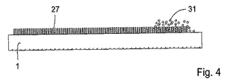
図4において、基板1は、吸収粒子31が垂直突起間に配置されている遠位部で、実質的に垂直な突起で構成されるように示された流体流路27を、支えている。この実施形態には、装置に対する吸収粒子の良好な接着と、液体と粒子との間の良好な接触と、を確保するという利点がある。
In FIG. 4, the
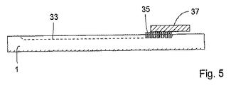
図5の実施形態では、基板1上で、流体流路33が、基板の表面の溝又はチャネルの形で設けられており、チャネルの遠位部に突起の領域35が設けられており、この突起が、チャネルと、突起を通してチャネルと流体連通する吸収区域37と、の間に、移行部を形成している。この実施形態には、チャネル又は溝内の流体と、突起に設けられる吸収区域と、の間での良好な接触を、確保するという利点がある。
In the embodiment of FIG. 5, a
ポリアクリル結晶及びゲルといった高吸水材或いは高吸収性重合体(SAP)は、当業者にとって公知であり、商業的に利用可能である(例えば、DRYTECH(登録商標)、ダウ・ケミカル社、米国)。 Superabsorbents such as polyacrylic crystals and gels or superabsorbent polymers (SAP) are known to those skilled in the art and are commercially available (eg, DRYTECH®, Dow Chemical Company, USA). .
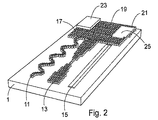
この実施形態は、図2に示されている。図2は、各々が別個の吸収区域17,19,21と流体連通する3つの流体流路11,13,15を有する装置1の斜視図である。この実施形態において、第3流体流路15は、対応する第3吸収区域25に繋がる基板1の表面にある溝として示されている。これにより、第3流体流路それ自体は、毛管流を支持しない。
This embodiment is illustrated in FIG. FIG. 2 is a perspective view of the
図2において、第1吸収区域17は、区域17に取り付けられてこれと流体接続する、吸収パッド23を、備えている。第2吸収区域19は、区域の実質的に垂直な突起間に配置された、吸収材料を、備えている。第3吸収区域21は、区域の実質的に垂直な突起の上及び間に配置された、発泡体を、備えている。
In FIG. 2, the first
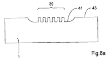
図6aは、チャネルの底部すなわち「床部」が、基板の全般的な表面43よりも低くなるように、実質的に垂直な突起39を備えた流体流路が、基板のチャネル内に設けられた、実施形態の断面図である。製造を簡単にして垂直突起に対する防護を行うために、突起の最上部が表面43と同じレベルであることが望ましい。
FIG. 6a shows that a fluid flow path with substantially
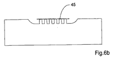
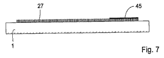
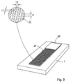
図6bは、カバー又は箔45が垂直突起の最上部に設けられている、関連する実施形態を、示す。これは特に、突起によって画定される容積を正確に限定するのに役立つ。この実施形態は、例えば、吸収区域の疎水性特性に影響を与えることにより、区域の吸収容量又は吸収率を改変し、好ましくは向上させるために、用いることもできる。図9の詳細図は、高さH、直径D、及び突起間距離t1,t2がどのように計測されるかを示す。 FIG. 6b shows a related embodiment in which a cover or foil 45 is provided on top of the vertical protrusion. This particularly helps to accurately limit the volume defined by the protrusions. This embodiment can also be used to modify, preferably improve, the absorption capacity or absorption rate of the area, for example by affecting the hydrophobic properties of the absorption area. The detailed view of FIG. 9 shows how the height H, diameter D, and interprotrusion distances t1, t2 are measured.
一実施形態において、マイクロピラー又は突起は、約15〜約150マイクロメートル好ましくは約30〜約100マイクロメートルの間の高さ、約10〜約160マイクロメートル好ましくは20〜約80マイクロメートルの直径、互いに約5〜約200マイクロメートル好ましくは10〜約100マイクロメートルの突起間距離を有する。流路は、約5〜約500ミリメートル好ましくは約10〜約100ミリメートルの長さと、約1〜約30ミリメートル好ましくは約2〜約10ミリメートルの幅と、を有する場合もある。なお、この文脈において、本発明の実施形態による装置が必ずしもマイクロピラーの均一部位を持たなくてもよく、マイクロピラーの寸法、形状、及び突起間距離が、装置で異なる場合もある。同様に、流路の形状及び寸法も変わる場合がある。 In one embodiment, the micropillars or protrusions have a height between about 15 and about 150 micrometers, preferably between about 30 and about 100 micrometers, and a diameter between about 10 and about 160 micrometers, preferably between 20 and about 80 micrometers. Have an interprotrusion distance of about 5 to about 200 micrometers, preferably 10 to about 100 micrometers. The flow path may have a length of about 5 to about 500 millimeters, preferably about 10 to about 100 millimeters, and a width of about 1 to about 30 millimeters, preferably about 2 to about 10 millimeters. In this context, the device according to the embodiment of the present invention does not necessarily have a uniform portion of the micropillar, and the size, shape, and interprotrusion distance of the micropillar may vary from device to device. Similarly, the shape and dimensions of the flow path may change.
他の一実施形態において、少なくとも1つの流体流路は、それ自体は毛管流を支持しない流路である。このような流路の主要例は、毛管作用が起こらないような大径の、開いた又は閉じた、流路である。この種類の流路は、重力、遠心力、ポンプ力、又は他の外的影響により、過剰な液体が加えられるときだけ液体で満たされる。本発明によれば、毛管を支持することのできない流路は吸収区域に接続でき、この場合、吸収区域が流路内に流れを確立することになる。好ましい実施形態によれば、上記区域は、区域に引かれ且つ任意の培養区域及び反応区域を通過させる体積が、この区域の体積によって決められ、且つ、装置に加えられるサンプルの量によって決められないように、設計される。 In another embodiment, the at least one fluid flow path is a flow path that does not itself support capillary flow. A major example of such a channel is a large, open or closed channel that does not cause capillary action. This type of flow path is filled with liquid only when excess liquid is added due to gravity, centrifugal force, pumping force, or other external influences. According to the present invention, the flow path that cannot support the capillary can be connected to the absorption area, in which case the absorption area establishes a flow in the flow path. According to a preferred embodiment, the zone is drawn to the zone and the volume that passes through any culture zone and reaction zone is determined by the volume of this zone and not by the amount of sample applied to the device. As designed.
他の好ましい一実施形態によれば、本発明による装置は、同一吸収区域又は同一区域のセクションに繋がる2つ以上の並列流路を、備えている。この実施形態による装置は、複数の被検体が1つのサンプルで測定される分析検査に対して、特に適している。各流体流路は、それ自体の試薬のセットを有し、サンプルの一部が、各流路に入り、流路内に配置された又はその他の形の特定の試薬と、反応する。 According to another preferred embodiment, the device according to the invention comprises two or more parallel flow paths leading to the same absorption zone or sections of the same zone. The apparatus according to this embodiment is particularly suitable for an analytical test in which a plurality of subjects are measured with one sample. Each fluid channel has its own set of reagents, and a portion of the sample enters each channel and reacts with a particular reagent placed in or otherwise in the channel.
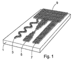
図1は、表面に対して実質的に垂直な突起を有する領域として示された吸収区域9にそれぞれ流体接続する3つの流体流路3,5,7、を有する基板1を、備えた実施形態を概略的に示している。ここで、3つ全ての流体流路は、毛管流を生成するか支持することのできる突起を備えている。分析検査で適用される場合、サンプルは、図1及び2で示されるように、流路3,5,7の近位端又はその近く、もしくは図3,4又は5で示される流路27の左側端部に、加えられる。
FIG. 1 shows an embodiment comprising a
この実施形態及び類似の実施形態によれば、並列流路の流体の同時流又は逐次流が、この流路の長さ、幅、深さ、又は他の特性を適応させることで得られる。例えば、長い蛇行流路(例えば、図1及び3において、符号3及び11で示されるもの)は、長い培養時間が所望されるときに用いられる。複数の試薬が加えられるか、或いは同一サンプルに対して複数の分析を行う場合には、分岐流路が用いられる。サンプルに対して複数の分析が行われる適用の1つの例は、種々のタンパク質の存在及び/又は活性が、1つのサンプルで同時に分析される多重分析の分野である。他の適用としては、単一サンプルの特定グループのタンパク質の構成要素の有無及び/又は活性を多重検出すること、例えば、リン酸化及びユビキチン化といった異なるタンパク質の変質を同時検出すること、特定の捕獲タンパク質を結合するタンパク質及び特定の核酸シーケンスを結合するタンパク質を1つのサンプル中で同時検出するものがある。ビードベースの多重分析は当業者にとって公知であり、固定化された反応物と検出結合体をもつ適切なビードは、商業的に利用可能である。ビード技術は、本発明による装置、或いは本発明の装置で用いられる基板に対して固定された反応物及び結合体に、適応可能である。 According to this embodiment and similar embodiments, simultaneous or sequential flow of fluids in parallel flow paths is obtained by adapting the length, width, depth, or other characteristics of the flow paths. For example, long serpentine channels (eg, those shown as 3 and 11 in FIGS. 1 and 3) are used when long incubation times are desired. When a plurality of reagents are added or a plurality of analyzes are performed on the same sample, a branch channel is used. One example of an application where multiple analyzes are performed on a sample is in the field of multiplex analysis where the presence and / or activity of various proteins is analyzed simultaneously on a single sample. Other applications include multiplex detection of the presence and / or activity of a particular group of proteins in a single sample, eg, simultaneous detection of alterations in different proteins such as phosphorylation and ubiquitination, specific capture Some detect proteins that bind proteins and proteins that bind specific nucleic acid sequences simultaneously in one sample. Bead-based multiplex analysis is known to those skilled in the art, and suitable beads with immobilized reactants and detection conjugates are commercially available. The bead technology can be applied to the reactants and conjugates fixed to the device according to the invention or to the substrate used in the device of the invention.
本発明の一実施形態によれば、吸収区域の流体容量は、輸送される流体の体積と、少なくとも等しいか、好ましくは少なくとも2倍である。好ましい実施形態によれば、吸収区域の容量は、反応区域内に引き込まれたサンプルの量を決め、装置をサンプルの計測とは独立させる。 According to an embodiment of the invention, the fluid capacity of the absorption zone is at least equal to the volume of fluid to be transported, preferably at least twice. According to a preferred embodiment, the volume of the absorption zone determines the amount of sample drawn into the reaction zone and makes the device independent of sample measurement.
本発明の実施形態による実質的に垂直な突起には、好ましくは、当該の分析検査に適した、所望される流量及び容量に適した親水性特性を含む、化学的、生物学的、又は生理学的特性が与えられる。1つの例として、デキストランで突起を被膜するものがある。 Substantially vertical protrusions according to embodiments of the present invention preferably include chemical, biological, or physiological, including hydrophilic properties suitable for the desired flow rate and volume suitable for the analytical test concerned. Characteristics are given. One example is to coat the protrusions with dextran.
本発明は更に、基板上にある少なくとも1つの流体流路内又はそれに沿った流体輸送を取り扱うための方法を利用可能にし、ここで、流路内の流体輸送は、流路と流体接触するように配置された吸収区域によって確立及び/又は維持され、この吸収区域は、非多孔質基板でできた区域であり、この区域は、表面に対して実質的に垂直な突起を有し、この突起は、この区域上で流体の側方毛管流が得られるような、高さH、直径D、及び突起間距離t1,t2を有する。 The present invention further makes available a method for handling fluid transport in or along at least one fluid flow path on a substrate, wherein the fluid transport in the flow path is in fluid contact with the flow path. Established and / or maintained by an absorbent area disposed on the surface, the absorbent area being an area made of a non-porous substrate, the area having a protrusion substantially perpendicular to the surface, the protrusion Has a height H, a diameter D, and an interprotrusion distance t1, t2 such that a lateral capillary flow of fluid is obtained over this area.
この方法において、基板は、好ましくは、使い捨て可能な分析装置の少なくとも一部又はセクションを形成する。 In this method, the substrate preferably forms at least a part or section of a disposable analytical device.
好ましい実施形態において、吸収材料がこの吸収区域に配置される。この吸収材料は、好ましくは、ガラス繊維を含むことのできるセルロースといった強化セルロース含有材料を含むセルロース含有材料、ニトロセルロース、吸湿性塩、親水性重合体構造、吸湿性固体粒子、架橋デクトラン又はアガローズ、或いは架橋ポリアクリルアミドの多孔性粒子といった屈曲性高分子鎖の架橋ネットワークの多孔性粒子、高吸水性材料、及びポリウレタンフォーム等、から選択される。 In a preferred embodiment, an absorbent material is placed in this absorbent area. This absorbent material is preferably a cellulose-containing material comprising a reinforced cellulose-containing material such as cellulose that can contain glass fibers, nitrocellulose, hygroscopic salts, hydrophilic polymer structures, hygroscopic solid particles, crosslinked dectran or agarose, Alternatively, it is selected from porous particles of a crosslinked network of flexible polymer chains such as porous particles of crosslinked polyacrylamide, a superabsorbent material, polyurethane foam, and the like.
本発明による方法において、サンプルは、2つ以上の流体流路に分割でき、ここで、少なくとも1つの流体流路は、毛管流を支持する流路である。或いは、少なくとも1つの流体流路は、それ自体は毛管流を支持しない流路である。 In the method according to the invention, the sample can be divided into two or more fluid channels, wherein at least one fluid channel is a channel that supports the capillary flow. Alternatively, the at least one fluid flow path is a flow path that does not itself support capillary flow.
図面は単に非限定的な方式で本発明の実施形態を示すだけであり、その特性は、明らかに、これらの実施形態間で取り換え可能である。例えば、図5における溝又はチャネル33は、図1における1つ以上の流体流路3,5,7又は図2における流体流路11,13,15の、それぞれの代わりとしても、同じく適している。同様に、蛇行流路3,11、砂時計型流路5,13、及び実質的に真っ直ぐな流路又は溝7,15,33、のように示された、異なる形状の流路が、例示されている。本発明による装置及び方法における流体流路も同様に、迷路型、分岐型、相互接続型、又は当業者にとって公知の他の構成の場合もある。
The drawings merely illustrate embodiments of the invention in a non-limiting manner, and the characteristics can obviously be interchanged between these embodiments. For example, the groove or
一実施形態によれば、そのサンプル或いはその一部は、同一の吸収区域又は同一区域のセクションに繋がる並列流路を通って、導かれる。 According to one embodiment, the sample or part thereof is directed through parallel flow paths that lead to the same absorption area or sections of the same area.
他の一実施形態によれば、並列流路の流体の同時流又は逐次流が、この流路の、長さ、幅、深さ、又は他の特性を適応させることで得られる。 According to another embodiment, simultaneous or sequential flow of fluids in parallel channels is obtained by adapting the length, width, depth, or other characteristics of the channels.
更に、本発明の方法によれば、吸収区域の流体容量は、輸送される流体の体積と、少なくとも等しいか、好ましくは少なくとも2倍である。本発明の好ましい実施形態によれば、吸収区域の吸収容量は、反応区域、検出区域、及び任意の培養区域、を含む流体流路、を通して引き込まれる、サンプル及び/又は試薬の量を、決める。したがって、この方法は、サンプル又は試薬の正確な計測ステップを含み、加えられるサンプル又は試薬の量とは独立したものになる。 Furthermore, according to the method of the invention, the fluid capacity of the absorption zone is at least equal to the volume of fluid to be transported, preferably at least twice. According to a preferred embodiment of the invention, the absorption capacity of the absorption zone determines the amount of sample and / or reagent drawn through the fluid flow path including the reaction zone, the detection zone, and any culture zone. This method thus includes an accurate measurement step of the sample or reagent and is independent of the amount of sample or reagent added.
本発明は、本発明及びその実施形態により画定される装置、を備えた分析又は診断試験装置とともに、ここで画定された装置又はステップを用いることを含む何らかの方法を、カバーする。 The present invention covers any method comprising using the apparatus or steps defined herein together with an analytical or diagnostic test apparatus comprising the apparatus defined by the present invention and its embodiments.
(利点)
本発明の実施形態により、従来型の吸収パッドを更に小型の構造で置き換えることができるようになるが、ここで、基本となる垂直突起によって、吸収区域の均一性と信頼性が確保される。垂直突起により、流体流路から吸収区域までの滑らかな移行と、この吸収区域内でのサンプル流体の安定した分布と、が保証される。
(advantage)
Embodiments of the present invention allow a conventional absorbent pad to be replaced with a more compact structure, where the basic vertical protrusions ensure the uniformity and reliability of the absorbent area. The vertical projections ensure a smooth transition from the fluid flow path to the absorption zone and a stable distribution of the sample fluid within this absorption zone.
この実施形態により、検出区域及び選択可能な培養区域を含め、流体流路を通して引き込まれるサンプル及び/又は試薬の量を正確に測定し調節できるようになる。 This embodiment allows accurate measurement and adjustment of the amount of sample and / or reagent drawn through the fluid flow path, including the detection zone and selectable culture zone.
この実施形態により、同様に、既存の試験の感度調節が簡単になり、これは小さな体積又は大きな体積のサンプルに対しても、同様に適用できる。 This embodiment also simplifies the sensitivity adjustment of existing tests, which can be applied to small or large volume samples as well.
吸収区域をカバーするための箔の利用は、非常に正確に体積を画定することを助けるだけではなく、流速を改変するためにこれを開くこともできる。同一の構成と同一の体積で、構造に対して異なる箔を適用することで、流速を調節できる。 The use of a foil to cover the absorption area not only helps to define the volume very accurately, but can also be opened to modify the flow rate. The flow rate can be adjusted by applying different foils to the structure with the same configuration and the same volume.
この実施形態は、特に、同一の流路と、容量、流れ、及び反応時間に関して高度に繰り返し可能な特性と、を有する使い捨て可能な装置の、大量生産にとって適している。この実施形態は、定義のはっきりしない繊維状材料の全て又はその一部を置き換える、良く特徴付けられた重合体材料から、製造される場合に、適している。 This embodiment is particularly suitable for mass production of disposable devices having the same flow path and highly repeatable properties with respect to volume, flow and reaction time. This embodiment is suitable when manufactured from a well-characterized polymeric material that replaces all or part of the undefined fibrous material.
この実施形態により、更に、大きな間隔内で正確に吸収容量を調節することができるようになり、使い捨て可能な分析装置を種々の用途に対して合わせることが可能になる。 This embodiment also allows the absorption capacity to be adjusted accurately within a large interval, allowing the disposable analyzer to be tailored for various applications.
更なる利点については、記述、図、及び非限定的な例を、研究すれば、当業者にとって明らかになるであろう。 Further advantages will become apparent to those skilled in the art after studying the description, figures, and non-limiting examples.
(材料及び方法)
WO03/103835号に記載のマイクロピラー構造は、Amic AB社、ウプサラ、スウェーデンにより製造され、毛管流路と、吸収区域に対する移行及び支持と、の両方を構成するように、用いられた。試験される構造を含むポジ原型は、ケイ酸製構造体をエッチングすることで作製され、ニッケル製で作製されたネガ型は、このケイ酸製原型を用いて作製された。複数の試験構成は、ネガ型に対する熱可塑性プラスチック押し出しにより作製され、1ミリメートルの厚さのポリプロピレン製ディスク上に構造体を生成したものであるが、これは、垂直突起又はマイクロピラーで構成される流体流路又は開いた流路を各々がもつストリップに切断されたものである。このストリップは、実用上の理由から、典型的な顕微鏡送り台と同じ寸法、すなわち20×76ミリメートルであった。
(Materials and methods)
The micropillar structure described in WO 03/103835 was manufactured by Amic AB, Uppsala, Sweden, and was used to constitute both the capillary flow path and the transition and support for the absorbent area. A positive prototype containing the structure to be tested was made by etching a silicate structure, and a negative mold made of nickel was made using this silicate prototype. Several test configurations were made by extruding a thermoplastic to a negative mold and produced the structure on a 1 mm thick polypropylene disk, which consisted of vertical protrusions or micropillars. Cut into strips each having a fluid flow path or an open flow path. This strip was the same size as a typical microscope carriage, ie 20 × 76 millimeters, for practical reasons.
マイクロピラーは、高さ69マイクロメートル、直径46マイクロメートルという寸法を持ち、互いに約29マイクロメートルの距離をおいて置かれた。流路は、25ミリメートルの長さ、5ミリメートルの幅を、持っていた。最後の5ミリメートルは、吸収材料のサポート部として用いられ、約5×5ミリメートルの吸収区域を画定するものであった。 The micropillars were 69 micrometers high and 46 micrometers in diameter and were placed at a distance of about 29 micrometers from each other. The flow path had a length of 25 millimeters and a width of 5 millimeters. The last 5 millimeters were used as a support for the absorbent material and defined an absorbent area of about 5 × 5 millimeters.
定常状態の流れは、0.25%トリトンX−100、0.5%BSA、0.3モルNaCl、及び0.1モルトリス緩衝液pH7.0、で構成された緩衝液、10マイクロリットルを、5回連続して塗付することで測定された。緩衝液の喪失時間が計測された。最後の5は、定常状態計算のために用いられた。 Steady-state flow consists of 10 microliters of buffer composed of 0.25% Triton X-100, 0.5% BSA, 0.3 molar NaCl, and 0.1 molar Tris buffer pH 7.0, It was measured by applying 5 times in succession. Buffer loss time was measured. The last 5 was used for steady state calculations.
(例1.吸収手段として多孔性マイクロビードを用いる毛管流)
乾燥したセファデックスG25(媒体、アマシャム・バイオサイエンス社、ウプサラ、スウェーデン)25ミリグラムが、垂直突起間で分散するように、流路の末端に置かれた。流量は、上述の緩衝液の付加により測定された。結果は表1で示される。
(Example 1. Capillary flow using porous microbeads as absorbing means)
25 milligrams of dried Sephadex G25 (media, Amersham Biosciences, Uppsala, Sweden) was placed at the end of the flow path so as to be distributed between the vertical protrusions. The flow rate was measured by adding the above buffer. The results are shown in Table 1.

同じマイクロビードセファデックスG25(超微粉、アマシャム・バイオサイエンス社、ウプサラ、スウェーデン)の他の部分を用いた予備実験では、粒子の大きさが流れに対して大きな影響を与えることが示された。 Preliminary experiments with other parts of the same microbead Sephadex G25 (ultrafine powder, Amersham Biosciences, Uppsala, Sweden) showed that particle size has a significant effect on flow.
(例2.吸収手段としてセルロース/ガラス繊維フィルタを用いる毛管流)
長さ25ミリメートル、幅5ミリメートルのCF6(ワットマン社、メイドストーン、英国)吸収フィルタが、垂直突起上に静置されるように、流路の末端に置かれた。流量は、上述の緩衝液の付加により測定された。結果は表2で示される。
(Example 2. Capillary flow using cellulose / glass fiber filter as absorption means)
A CF6 (Whatman, Maidstone, UK) absorption filter, 25 millimeters long and 5 millimeters wide, was placed at the end of the flow path so as to rest on the vertical protrusion. The flow rate was measured by adding the above buffer. The results are shown in Table 2.
この結果は、流体流路と突起と吸収フィルタ材料と、の間で、良好に機能するインターフェイスが形成され、顕著な流量が得られること、を示している。 This result shows that a well-functioning interface is formed between the fluid flow path, the protrusion and the absorption filter material, and a significant flow rate is obtained.
(例3.吸収手段として発泡材料を用いる毛管流)
ポリウレタンフォームは、垂直突起を構成する領域内で、流路の端末において装置内の現位置で硬化された。発泡体は、突起間のスペースを満たし、残りの流路との良好な流体連通をもたらした。発泡体により100マイクロリットルが吸収される時間が、異なるサンプルについて3回測定された。結果(表3)によれば、発泡体が吸収区域の働きをして、関連流れが得られることが示された。ポロシティ、硬化、及び他の特性、に関する発泡体の最適化により、良好な流量をもたらすこともできることが予想される。
(Example 3. Capillary flow using foam material as absorption means)
The polyurethane foam was cured at the current location in the device at the end of the flow path in the area constituting the vertical projection. The foam filled the space between the protrusions and provided good fluid communication with the remaining channels. The time taken for 100 microliters to be absorbed by the foam was measured three times for different samples. The results (Table 3) showed that the foam acts as an absorption zone and an associated flow is obtained. It is anticipated that foam optimization with respect to porosity, cure, and other properties can also provide good flow rates.
(例4.箔依存の流れ)
試験ストリップは、高さ69マイクロメートル、直径46マイクロメートルの寸法を持つマイクロピラーの領域で構成されるか、或いはこれに繋がる流体流路を持つように作製され、互いにおよそ29マイクロメートルの距離に置かれた。流路は、約25ミリメートルの長さと4ミリメートルの幅を持っていた。接着箔で覆われたサンプル付加に対する遠位端。親水性及び疎水性の接着剤を持つ異なる箔が、試験された(アドヒーシブ・リサーチ社、米国によって提供されたサンプル)。
(Example 4. Flow depending on foil)
The test strip is made up of a region of micropillars having a height of 69 micrometers and a diameter of 46 micrometers, or made with fluid channels leading to it, at a distance of approximately 29 micrometers from each other. Was placed. The flow path had a length of about 25 millimeters and a width of 4 millimeters. Distal end for sample addition covered with adhesive foil. Different foils with hydrophilic and hydrophobic adhesives were tested (samples provided by Adhesive Research, USA).
流量は、0.015%Tween−20が加えられたリン酸緩衝液サリンを用いて、試験された。結果は表4で示される。 The flow rate was tested using phosphate buffered saline with 0.015% Tween-20 added. The results are shown in Table 4.
結果は、親水性箔を持つ幅広い流体流路(4ミリメートル)の遠位端を覆うことが、流速を顕著に大きくすることを、示している。更に狭い流体流路(2ミリメートル)で得られる僅かな改善は、構造上の差によるものと考えられる。狭い流体流路において、露出される側の影響が大きくなる。例えば、異なる程度の濡れ挙動又は親水性を選択することで、接着剤の特性を調節すれば、種々のサンプル流体に対して流速を正確に調節できる。 The results show that covering the distal end of a wide fluid flow path (4 millimeters) with hydrophilic foil significantly increases the flow rate. The slight improvement obtained with a narrower fluid flow path (2 millimeters) is believed to be due to structural differences. In a narrow fluid flow path, the influence on the exposed side becomes large. For example, by adjusting the properties of the adhesive by selecting different degrees of wetting behavior or hydrophilicity, the flow rate can be accurately adjusted for various sample fluids.
一般に、全ての実験結果は、本発明の概念が実際に作用し、吸収区域を設けることが、本発明による装置の吸収容量と流速とを顕著に増加させること、を示している。突起又はマイクロピラー構造に対して密着して配置された箔を用いた実験は、非常に正確に体積を画定するだけでなく、流速にも影響すること、を示している。 In general, all experimental results show that the concept of the present invention actually works and that providing an absorption zone significantly increases the absorption capacity and flow rate of the device according to the present invention. Experiments with foils placed in close contact with protrusions or micropillar structures have shown that not only define the volume very accurately, but also affect the flow rate.
本発明は、本発明者にとって現在知られているベストモードを構成する好ましい実施形態に関して述べられているが、当業者にとって明らかな種々の変更及び改変を、ここで添付される請求項で示された本発明の範囲から逸脱することなく、行う場合もあることは、明らかである。
なお、本発明の好ましい実施態様は以下の通りである。
(1) 分析される流体を取り扱うための装置であって、
前記装置が、
基板表面を有する非多孔性基板と、
第1端部と、前記第1端部の反対側の第2端部と、を有する少なくとも1つの流体流路と、
前記少なくとも1つの第1流路の前記第2端部と流体接触する少なくとも1つの吸収区域と、を備えており、
前記少なくとも1つの吸収区域が、前記基板表面に対して実質的に垂直な突起を、備えており、
前記突起が、前記少なくとも1つの流体流路の前記第2端部から、前記吸収区域と接触するように置かれた流体の、前記基板表面に対して側方の毛管流を生成することのできる、高さ、直径、及び突起間距離を有している、ことを特徴とする装置。
(2) 前記装置が、使い捨て可能な分析装置又はその装置の一部である、実施態様1に記載の装置。
(3) 箔が、前記吸収区域の前記垂直突起上に設けられている、実施態様1に記載の装置。
(4) 前記箔が、前記少なくとも1つの流体流路内の流速に影響を及ぼす親水特性を、有している、実施態様3に記載の装置。
(5) 吸収材料が、前記吸収区域の上又は中に設けられている、実施態様1に記載の装置。
(6) 前記吸収材料が、セルロース含有材料、吸湿性塩、親水性重合体構造、親水性固体粒子、屈曲性高分子鎖の架橋ネットワークの多孔性粒子、高吸水性材料、及び熱可塑性プラスチック発泡体材料、の中から選択される、実施態様5に記載の装置。
(7) 前記吸収材料が、架橋デキストラン又はアガローズの粒子を含んでいる、実施態様5に記載の装置。
(8) 前記吸収材料が、ポリウレタンフォームである、実施態様5に記載の装置。
(9) 前記吸収材料が、高吸収性である、実施態様5に記載の装置。
(10) 前記少なくとも1つの流体流路が、毛管流を支持する流路である、実施態様1に記載の装置。
(11) 前記少なくとも1つの流体流路が、それ自体は毛管流を支持しない流路である、実施態様1に記載の装置。
(12) 前記装置が、同一の吸収区域又は同一区域のセクションまで繋がる並列流路を、備えている、実施態様1に記載の装置。
(13) 前記装置が、同一又は異なる吸収容量を示す2つ以上の吸収区域まで繋がる並列流路を、備えている、実施態様1に記載の装置。
(14) 1つ或いは両方の吸収区域が、箔で覆われており、該区域が、同一又は異なる流体容量を示している、実施態様13に記載の装置。
(15) 前記吸収区域の前記流体容量が、輸送される流体の体積と、少なくとも等しいか、好ましくは少なくとも2倍である、実施態様1乃至14の内のいずれか1つの項に記載の装置。
(16) 前記流体流路に沿って供給されるサンプルの体積が、前記吸収区域の前記吸収容量によって決められ、前記装置に対して加えられるサンプルの量によって決められない、実施態様1乃至14の内のいずれか1つの項に記載の装置。
(17) 基板表面を有する非多孔性基板上の少なくとも1つの流体流路内で流体輸送を取り扱う方法であって、
少なくとも1つの流体流路が、第1端部と、前記第1端部の反対側の第2端部と、を有し、
少なくとも1つの吸収区域が、前記少なくとも1つの第1流路の前記第2端部と流体接触し、
前記流路の流体輸送が、1つの吸収区域によって確立及び/又は維持され、
前記少なくとも1つの吸収区域が、前記基板表面に対して実質的に垂直な突起を備え、
前記突起が、前記少なくとも1つの流体流路の前記第2端部から、前記吸収区域と接触するように置かれた流体の、前記基板表面に対して側方の毛管流を生成することのできる、高さ、直径、及び突起間距離を、有することを特徴とする方法。
(18) 前記基板が、使い捨て可能な分析装置の一部である、実施態様17に記載の方法。
(19) 箔が、前記吸収区域の前記垂直突起上に設けられる、実施態様17に記載の方法。
(20) 前記装置の流速が、前記箔の親水特性の選択による影響を受ける、実施態様19に記載の方法。
(21) 吸収材料が、前記吸収区域の上又は中に設けられる、実施態様17に記載の方法。
(22) 前記吸収材料が、セルロース含有材料、吸湿性塩、親水性重合体構造、屈曲性高分子鎖の架橋ネットワークの多孔性粒子、固体吸湿性粒子、高吸水性材料、及び熱可塑性プラスチック発泡体物質、の中から選択される、実施態様21に記載の方法。
(23) 前記少なくとも1つの流体流路が、毛管流を支持する流路である、実施態様17に記載の方法。
(24) 前記少なくとも1つの流体流路が、それ自体は毛管流を支持しない流路である、実施態様17に記載の方法。
(25) 前記装置が、同一の吸収区域又は同一区域のセクションまで繋がる並列流路を備え、同一又は異なる吸収容量を示す、実施態様17に記載の方法。
(26) 1つ或いは両方の吸収区域が、箔で覆われ、該区域が、同一又は異なる吸収容量を示す、実施態様17に記載の方法。
(27) 前記吸収区域の前記容量が、輸送される流体の体積と少なくとも等しい、実施態様17乃至26の内のいずれか1つの項に記載の方法。
(28) 前記流体流路に沿って供給されるサンプルの体積が、前記吸収区域の前記吸収容量によって決められ、前記装置に対して加えられるサンプルの量によって決められない、実施態様17乃至26の内のいずれか1つの項に記載の方法。
(29) 実施態様1乃至16の内のいずれか1つの項に記載の装置を備えたことを特徴とする分析又は診断試験装置。
(30) 実施態様17乃至28の内のいずれか1つの項に記載のステップを備えたことを特徴とする方法。
Although the present invention has been described with reference to preferred embodiments constituting the best mode presently known to the inventors, various changes and modifications apparent to those skilled in the art are set forth in the appended claims. Obviously, there may be cases where the present invention is carried out without departing from the scope of the present invention.
The preferred embodiments of the present invention are as follows.
(1) A device for handling the fluid to be analyzed,
The device is
A non-porous substrate having a substrate surface;
At least one fluid flow path having a first end and a second end opposite the first end;
At least one absorption zone in fluid contact with the second end of the at least one first flow path;
The at least one absorption area comprises a protrusion substantially perpendicular to the substrate surface;
The protrusion can generate a capillary flow laterally relative to the substrate surface of a fluid placed in contact with the absorption area from the second end of the at least one fluid flow path. , Having a height, a diameter, and an interprotrusion distance.
(2) The apparatus according to
(3) The apparatus according to
(4) The apparatus of
(5) The apparatus of
(6) The absorbent material is a cellulose-containing material, a hygroscopic salt, a hydrophilic polymer structure, a hydrophilic solid particle, a porous particle of a crosslinked network of flexible polymer chains, a superabsorbent material, and a thermoplastic foam. Embodiment 6. The device according to embodiment 5, wherein the device is selected from body materials.
(7) The apparatus of embodiment 5, wherein the absorbent material comprises crosslinked dextran or agarose particles.
(8) The apparatus according to embodiment 5, wherein the absorbent material is polyurethane foam.
(9) The apparatus according to embodiment 5, wherein the absorbent material is highly absorbent.
(10) The apparatus of
(11) The apparatus of
(12) The apparatus of
(13) The device according to
14. The apparatus of
15. The apparatus according to any one of the preceding embodiments, wherein the fluid volume of the absorption zone is at least equal to, preferably at least twice, the volume of fluid being transported.
Embodiment 16: The volume of the sample supplied along the fluid flow path is determined by the absorption capacity of the absorption zone and not by the amount of sample applied to the device. A device according to any one of the preceding paragraphs.
(17) A method of handling fluid transport in at least one fluid flow path on a non-porous substrate having a substrate surface,
At least one fluid flow path has a first end and a second end opposite the first end;
At least one absorption zone is in fluid contact with the second end of the at least one first flow path;
Fluid transport in the flow path is established and / or maintained by one absorption zone;
The at least one absorption area comprises a protrusion substantially perpendicular to the substrate surface;
The protrusion can generate a capillary flow laterally relative to the substrate surface of a fluid placed in contact with the absorption area from the second end of the at least one fluid flow path. Having a height, a diameter, and an interprotrusion distance.
(18) A method according to
19. The method of
20. The method of
21. The method of
(22) The absorbent material is a cellulose-containing material, a hygroscopic salt, a hydrophilic polymer structure, a porous particle of a crosslinked network of flexible polymer chains, a solid hygroscopic particle, a superabsorbent material, and a thermoplastic foam. 22. The method according to
23. The method of
24. The method of
25. The method of
26. The method of
27. A method according to any one of
28. The embodiment of any one of embodiments 17-26, wherein the volume of sample supplied along the fluid flow path is determined by the absorption capacity of the absorption zone and not by the amount of sample applied to the device. A method according to any one of the preceding paragraphs.
(29) An analysis or diagnostic test apparatus comprising the apparatus according to any one of the
(30) A method comprising the steps according to any one of
Claims (25)
前記装置が、
基板表面を有する非多孔性基板と、
第1端部と、前記第1端部の反対側の第2端部と、を有する少なくとも1つの流体流路と、
前記少なくとも1つの流体流路の前記第2端部と流体接触する少なくとも1つの吸収区域と、を備えており、
前記少なくとも1つの吸収区域が、前記基板表面に対して実質的に垂直な突起を収納する、ある流体容量を持ち、
前記突起が、前記少なくとも1つの流体流路の前記第2端部から、前記吸収区域と接触するように置かれた流体の、前記基板表面に対して側方の、前記吸収区域の吸収容量を決める毛管流を生成することのできる、高さ、直径、及び突起間距離を有しており、
前記吸収区域の前記垂直突起上に箔が設けられており、当該箔が、前記少なくとも1つの流体流路内の流速に影響を及ぼす親水特性を有しており、
前記流体流路に沿って供給されるサンプルの体積が、前記吸収区域の前記吸収容量によって決められ、前記装置に対して加えられるサンプルの量によって決められない、
ことを特徴とする装置。 In a device for handling the fluid to be analyzed,
The device is
A non-porous substrate having a substrate surface;
At least one fluid flow path having a first end and a second end opposite the first end;
At least one absorption zone in fluid contact with the second end of the at least one fluid flow path;
The at least one absorption zone has a fluid volume containing a protrusion substantially perpendicular to the substrate surface;
An absorption capacity of the absorption area lateral to the substrate surface of the fluid, the protrusion being placed in contact with the absorption area from the second end of the at least one fluid flow path. Have a height, diameter, and interprotrusion distance that can produce a capillary flow that determines
A foil is provided on the vertical protrusion of the absorption area, the foil having hydrophilic properties that affect the flow velocity in the at least one fluid flow path;
The volume of the sample delivered along the fluid flow path is determined by the absorption capacity of the absorption zone and not by the amount of sample applied to the device;
A device characterized by that.
少なくとも1つの流体流路が、第1端部と、前記第1端部の反対側の第2端部と、を有し、
少なくとも1つの吸収区域が、前記少なくとも1つの流体流路の前記第2端部と流体接触し、
前記流路の流体輸送が、1つの吸収区域によって確立及び/又は維持され、
前記少なくとも1つの吸収区域が、前記基板表面に対して実質的に垂直な突起を収納する、ある流体容量を持ち、
前記突起が、前記少なくとも1つの流体流路の前記第2端部から、前記吸収区域と接触するように置かれた流体の、前記基板表面に対して側方の、前記吸収区域の吸収容量を決める毛管流を生成することのできる、高さ、直径、及び突起間距離を、有し、
前記吸収区域の前記垂直突起上に箔が設けられており、当該箔が、前記少なくとも1つの流体流路内の流速に影響を及ぼす親水特性を有しており、
前記流体流路に沿って供給されるサンプルの体積が、前記吸収区域の前記吸収容量によって決められ、前記装置に対して加えられるサンプルの量によって決められない、
ことを特徴とする方法。 In a method of handling fluid transport in at least one fluid flow path on a non-porous substrate having a substrate surface,
At least one fluid flow path has a first end and a second end opposite the first end;
At least one absorption zone is in fluid contact with the second end of the at least one fluid flow path;
Fluid transport in the flow path is established and / or maintained by one absorption zone;
The at least one absorption zone has a fluid volume containing a protrusion substantially perpendicular to the substrate surface;
An absorption capacity of the absorption area lateral to the substrate surface of the fluid, the protrusion being placed in contact with the absorption area from the second end of the at least one fluid flow path. Having a height, a diameter, and an interprotrusion distance, capable of producing a capillary flow to determine
A foil is provided on the vertical protrusion of the absorption area, the foil having hydrophilic properties that affect the flow velocity in the at least one fluid flow path;
The volume of the sample delivered along the fluid flow path is determined by the absorption capacity of the absorption zone and not by the amount of sample applied to the device ;
A method characterized by that.
Applications Claiming Priority (3)
| Application Number | Priority Date | Filing Date | Title |
|---|---|---|---|
| SE0501418-8 | 2005-06-20 | ||
| SE0501418A SE0501418L (en) | 2005-06-20 | 2005-06-20 | Method and means for effecting liquid transport |
| PCT/SE2006/000745 WO2006137785A1 (en) | 2005-06-20 | 2006-06-20 | Method and means for creating fluid transport |
Publications (2)
| Publication Number | Publication Date |
|---|---|
| JP2008547017A JP2008547017A (en) | 2008-12-25 |
| JP5451069B2 true JP5451069B2 (en) | 2014-03-26 |
Family
ID=37054375
Family Applications (1)
| Application Number | Title | Priority Date | Filing Date |
|---|---|---|---|
| JP2008518078A Expired - Fee Related JP5451069B2 (en) | 2005-06-20 | 2006-06-20 | Method and means for generating fluid transport |
Country Status (8)
| Country | Link |
|---|---|
| US (1) | US8821812B2 (en) |
| EP (1) | EP1893337B1 (en) |
| JP (1) | JP5451069B2 (en) |
| CN (1) | CN101203311B (en) |
| AU (1) | AU2006259886B2 (en) |
| BR (1) | BRPI0612248A2 (en) |
| SE (1) | SE0501418L (en) |
| WO (1) | WO2006137785A1 (en) |
Families Citing this family (87)
| Publication number | Priority date | Publication date | Assignee | Title |
|---|---|---|---|---|
| AU2003277153A1 (en) | 2002-09-27 | 2004-04-19 | The General Hospital Corporation | Microfluidic device for cell separation and uses thereof |
| SE0400662D0 (en) * | 2004-03-24 | 2004-03-24 | Aamic Ab | Assay device and method |
| US8921102B2 (en) | 2005-07-29 | 2014-12-30 | Gpb Scientific, Llc | Devices and methods for enrichment and alteration of circulating tumor cells and other particles |
| JP4934360B2 (en) * | 2006-07-05 | 2012-05-16 | 学校法人東京女子医科大学 | Cell culture support |
| WO2008142160A1 (en) * | 2007-05-23 | 2008-11-27 | Vrije Universiteit Brussel | Device for the distribution of sample and carrier liquid across a micro-fabricated separation channel |
| EP2217925A4 (en) * | 2007-12-13 | 2011-01-19 | Beckman Coulter Inc | Device and methods for detecting a target cell |
| US8008032B2 (en) * | 2008-02-25 | 2011-08-30 | Cellective Dx Corporation | Tagged ligands for enrichment of rare analytes from a mixed sample |
| SE533515C2 (en) * | 2008-04-16 | 2010-10-12 | Aamic Ab | Analysis procedure for simultaneous analysis of several analytes |
| US8974749B2 (en) * | 2008-06-16 | 2015-03-10 | Johnson & Johnson Ab | Assay device and method |
| US9285361B2 (en) * | 2008-07-03 | 2016-03-15 | Johnson & Johnson Ab | Method for the analysis of circulating antibodies |
| KR101102532B1 (en) * | 2008-07-10 | 2012-01-03 | 삼성전자주식회사 | A reagent cartridge, a microfluidic device including the reagent cartridge, a manufacturing method thereof, and a sample analysis method using the same |
| JP5139580B2 (en) * | 2008-08-26 | 2013-02-06 | 紅電醫學科技股▲分▼有限公司 | Analytical strip substrate |
| CN102099682B (en) * | 2008-08-29 | 2013-12-18 | 红电医学科技股份有限公司 | Fluid test strip |
| WO2010108310A1 (en) * | 2009-03-23 | 2010-09-30 | 红电医学科技股份有限公司 | Fluid test chip and method to make it |
| JP5816613B2 (en) * | 2009-04-23 | 2015-11-18 | ダブリン シティ ユニバーシティ | Lateral flow analyzer and method for monitoring coagulation |
| EP2281632B1 (en) | 2009-07-02 | 2013-11-13 | Amic AB | Capillary driven assay device and its manufacture |
| EP2270506A3 (en) | 2009-07-02 | 2011-03-09 | Amic AB | Amplified labeled conjugate for use in immunoassays |
| CA2777807A1 (en) | 2009-10-16 | 2011-04-21 | Amic Ab | An assay method and devices involving the use of magnetic particles |
| JP5490492B2 (en) * | 2009-10-30 | 2014-05-14 | 学校法人立命館 | Plasma separator and blood analyzer |
| GB201014316D0 (en) | 2010-08-27 | 2010-10-13 | Univ Dublin City | A agglutination assay method and device |
| US9451913B2 (en) * | 2010-12-10 | 2016-09-27 | Touchtek Labs, Llc | Transdermal sampling and analysis device |
| WO2012138701A1 (en) * | 2011-04-06 | 2012-10-11 | Ortho-Clinical Diagnostics, Inc | Assay device having rhombus-shaped projections |
| US9541480B2 (en) | 2011-06-29 | 2017-01-10 | Academia Sinica | Capture, purification, and release of biological substances using a surface coating |
| KR20130085991A (en) * | 2012-01-20 | 2013-07-30 | 오르토-클리니칼 다이아그노스틱스, 인코포레이티드 | Assay device having uniform flow around corners |
| KR20130085994A (en) * | 2012-01-20 | 2013-07-30 | 오르토-클리니칼 다이아그노스틱스, 인코포레이티드 | Assay device with multiple reagent cells |
| CN103212454B (en) | 2012-01-20 | 2019-06-04 | 奥索临床诊断有限公司 | Assay device with controllable sample size |
| EP2618151B1 (en) * | 2012-01-20 | 2016-07-20 | Ortho-Clinical Diagnostics, Inc. | Low volume assay device having increased sensitivity |
| JP6395999B2 (en) | 2012-01-20 | 2018-09-26 | オーソ−クリニカル・ダイアグノスティックス・インコーポレイテッドOrtho−Clinical Diagnostics, Inc. | Controlling fluid flow through an assay device |
| WO2013109821A1 (en) | 2012-01-20 | 2013-07-25 | Ortho-Clinical Diagnostics, Inc. | Assay device having multiplexing |
| CA2818332C (en) | 2012-06-12 | 2021-07-20 | Ortho-Clinical Diagnostics, Inc. | Lateral flow assay devices for use in clinical diagnostic apparatus and configuration of clinical diagnostic apparatus for same |
| CN107043424B (en) | 2012-08-21 | 2021-03-16 | 詹森药业有限公司 | Antibodies to risperidone and uses thereof |
| ES2978909T3 (en) | 2012-08-21 | 2024-09-23 | Janssen Pharmaceutica Nv | Antibodies to aripiprazole haptens and their use |
| HK1211958A1 (en) | 2012-08-21 | 2016-06-03 | Ortho-Clinical Diagnostics, Inc. | Antibodies to paliperidone and use thereof |
| CA2882562C (en) | 2012-08-21 | 2019-08-27 | Eric Hryhorenko | Antibodies to aripiprazole and use thereof |
| PL2888590T3 (en) | 2012-08-21 | 2020-11-30 | Janssen Pharmaceutica Nv | Antibodies to olanzapine and use thereof |
| EP2887952B1 (en) | 2012-08-21 | 2019-05-15 | Janssen Pharmaceutica NV | Antibodies to olanzapine haptens and use thereof |
| CN104736566A (en) | 2012-08-21 | 2015-06-24 | 奥索临床诊断有限公司 | Antibodies to paliperidone haptens and use thereof |
| PL3663317T3 (en) | 2012-08-21 | 2023-06-05 | Janssen Pharmaceutica Nv | Antibodies to quetiapine haptens and use thereof |
| EP2888284B1 (en) | 2012-08-21 | 2022-07-06 | Janssen Pharmaceutica NV | Antibodies to risperidone haptens and use thereof |
| PL2888592T3 (en) | 2012-08-21 | 2018-03-30 | Janssen Pharmaceutica Nv | Antibodies to quetiapine and use thereof |
| EP3321254B1 (en) | 2012-08-21 | 2020-08-12 | Janssen Pharmaceutica NV | Haptens of aripiprazole and their use in immunoassays |
| JP6359263B2 (en) | 2012-11-15 | 2018-07-18 | オーソ・クリニカル・ダイアグノスティックス・インコーポレーテッド | Quality / process control of lateral flow assay devices based on flow monitoring |
| JP6328655B2 (en) | 2012-11-15 | 2018-05-23 | オーソ・クリニカル・ダイアグノスティックス・インコーポレーテッド | Calibrate the assay using reaction time |
| CA3226224A1 (en) | 2013-02-04 | 2014-08-07 | Epona Biotech Ltd | Device and diagnostic methods for infections in mammals using serum amyloid a |
| KR20140100843A (en) * | 2013-02-07 | 2014-08-18 | 삼성전자주식회사 | Support for capturing glycated protein in a sample and device and method for measuring the glycated protein using the same |
| CA2841692C (en) | 2013-02-12 | 2023-08-22 | Zhong Ding | Reagent zone deposition pattern |
| JP2014173934A (en) * | 2013-03-07 | 2014-09-22 | Toshiba Corp | Semiconductor micro-analysis chip and manufacturing method thereof |
| JP5904958B2 (en) | 2013-03-07 | 2016-04-20 | 株式会社東芝 | Semiconductor micro-analysis chip and manufacturing method thereof |
| JP5951527B2 (en) | 2013-03-07 | 2016-07-13 | 株式会社東芝 | Specimen detection apparatus and detection method |
| JP2014173937A (en) * | 2013-03-07 | 2014-09-22 | Toshiba Corp | Semiconductor micro-analysis chip and analyte flowing method |
| EP2777499B1 (en) | 2013-03-15 | 2015-09-16 | Ortho-Clinical Diagnostics Inc | Rotatable fluid sample collection device |
| US10898116B2 (en) | 2013-03-15 | 2021-01-26 | Cambridge Medical Technologies LLC | Methods of manufacture to optimize performance of transdermal sampling and analysis device |
| EP2778679B1 (en) | 2013-03-15 | 2017-09-27 | Ortho-Clinical Diagnostics, Inc. | Rotable disk-shaped fluid sample collection device |
| JP6151128B2 (en) | 2013-08-12 | 2017-06-21 | 株式会社東芝 | Semiconductor micro-analysis chip and manufacturing method thereof |
| DE102013111759A1 (en) * | 2013-10-25 | 2015-04-30 | Bürkert Werke GmbH | Apparatus and method for assaying sample fluid |
| US10877031B2 (en) | 2013-12-06 | 2020-12-29 | Ortho-Clinical Diagnostics, Inc. | Assay device having a wash port |
| JP6278772B2 (en) * | 2014-03-19 | 2018-02-14 | テルモ株式会社 | Blood glucose measurement chip |
| TW201623605A (en) | 2014-04-01 | 2016-07-01 | 中央研究院 | Method and system for cancer diagnosis and prognosis |
| US9903858B2 (en) | 2014-07-23 | 2018-02-27 | Ortho-Clinical Diagnostics, Inc. | Multiplexing with single sample metering event to increase throughput |
| US10031085B2 (en) | 2014-07-24 | 2018-07-24 | Ortho-Clinical Diagnostics, Inc. | Point of care analytical processing system |
| US10071373B2 (en) | 2014-08-08 | 2018-09-11 | Ortho-Clinical Diagnostics, Inc. | Lateral-flow assay device having flow constrictions |
| US11033896B2 (en) | 2014-08-08 | 2021-06-15 | Ortho-Clinical Diagnostics, Inc. | Lateral-flow assay device with filtration flow control |
| US10073091B2 (en) | 2014-08-08 | 2018-09-11 | Ortho-Clinical Diagnostics, Inc. | Lateral flow assay device |
| TW201612308A (en) | 2014-08-26 | 2016-04-01 | Academia Sinica | Collector architecture layout design |
| GB2535998A (en) | 2015-02-27 | 2016-09-07 | Intelligent Fingerprinting Ltd | A device for receiving and analysing a sample |
| CN104880563A (en) * | 2015-04-08 | 2015-09-02 | 上海盛复源生物医药有限公司 | NGAL rapid detection reagent and preparation method thereof |
| CN104880562A (en) * | 2015-04-08 | 2015-09-02 | 上海盛复源生物医药有限公司 | L-FABP (Liver-Fatty Acid Binding Protein) rapid detection reagent and preparation method thereof |
| CN107636460A (en) | 2015-05-19 | 2018-01-26 | 奥索临床诊断有限公司 | Method for Improving Flow of Liquid Samples in Assay Devices |
| EP3390455A1 (en) | 2015-12-17 | 2018-10-24 | Janssen Pharmaceutica NV | Antibodies to quetiapine and use thereof |
| JP6949025B2 (en) | 2015-12-17 | 2021-10-13 | ヤンセン ファーマシューティカ エヌ.ベー. | Antibodies to risperidone and its use |
| US10656151B2 (en) | 2016-01-29 | 2020-05-19 | Ortho-Clinical Diagnostics, Inc. | Air capillary vent for a lateral flow assay device |
| US10107726B2 (en) | 2016-03-16 | 2018-10-23 | Cellmax, Ltd. | Collection of suspended cells using a transferable membrane |
| CN107469476A (en) * | 2016-06-07 | 2017-12-15 | 杨国勇 | Fluid handling device |
| CN107469478B (en) * | 2016-06-07 | 2023-06-06 | 苏州苏瑞膜纳米科技有限公司 | Fluid treatment device and preparation method thereof |
| WO2018152496A1 (en) | 2017-02-17 | 2018-08-23 | The Usa, As Represented By The Secretary, Dept. Of Health And Human Services | Compositions and methods for the diagnosis and treatment of zika virus infection |
| EP3615569A1 (en) | 2017-04-25 | 2020-03-04 | The U.S.A. As Represented By The Secretary, Department Of Health And Human Services | Antibodies and methods for the diagnosis and treatment of epstein barr virus infection |
| EP3655430A1 (en) | 2017-07-19 | 2020-05-27 | The U.S.A. as represented by the Secretary, Department of Health and Human Services | Antibodies and methods for the diagnosis and treatment of hepatitis b virus infection |
| CN108393105B (en) * | 2018-04-20 | 2023-08-25 | 华南师范大学 | Microfluidic chip, control system and control method thereof |
| WO2019213416A1 (en) | 2018-05-02 | 2019-11-07 | The Usa, As Represented By The Secretary, Dept. Of Health And Human Services | Antibodies and methods for the diagnosis, prevention, and treatment of epstein barr virus infection |
| EP3845909A4 (en) * | 2018-08-31 | 2022-05-18 | National Institute Of Advanced Industrial Science And Technology | DOSING DEVICE |
| GB201902769D0 (en) | 2019-03-01 | 2019-04-17 | Univ Court Of The Univ Of Aberdeen | Antibody molcules and uses thereof |
| US11633129B2 (en) | 2019-04-05 | 2023-04-25 | Cambridge Medical Technologies LLC | Non-invasive transdermal sampling and analysis device incorporating redox cofactors |
| WO2021011944A2 (en) * | 2019-07-18 | 2021-01-21 | Essenlix Corporation | Imaging based homogeneous assay |
| US11375931B2 (en) | 2019-08-08 | 2022-07-05 | Cambridge Medical Technologies LLC | Non-invasive transdermal sampling and analysis device incorporating an electrochemical bioassay |
| CA3209078A1 (en) * | 2021-01-29 | 2022-08-04 | Ortho-Clinical Diagnostics, Inc. | Diagnostic photonic biosensor methods, apparatus, and system |
| CA3251979A1 (en) | 2022-05-13 | 2024-08-22 | University Of Rochester | Multiplex photonic biosensor apparatus, system, and methods |
| CN116105967B (en) * | 2023-04-17 | 2023-06-20 | 四川省农业机械研究设计院 | Wind field experiment platform for crop lodging resistance test experiment |
Family Cites Families (23)
| Publication number | Priority date | Publication date | Assignee | Title |
|---|---|---|---|---|
| US5051237A (en) | 1988-06-23 | 1991-09-24 | P B Diagnostic Systems, Inc. | Liquid transport system |
| US6905882B2 (en) | 1992-05-21 | 2005-06-14 | Biosite, Inc. | Diagnostic devices and apparatus for the controlled movement of reagents without membranes |
| US6156270A (en) | 1992-05-21 | 2000-12-05 | Biosite Diagnostics, Inc. | Diagnostic devices and apparatus for the controlled movement of reagents without membranes |
| US6767510B1 (en) | 1992-05-21 | 2004-07-27 | Biosite, Inc. | Diagnostic devices and apparatus for the controlled movement of reagents without membranes |
| US6143576A (en) | 1992-05-21 | 2000-11-07 | Biosite Diagnostics, Inc. | Non-porous diagnostic devices for the controlled movement of reagents |
| US6391265B1 (en) | 1996-08-26 | 2002-05-21 | Biosite Diagnostics, Inc. | Devices incorporating filters for filtering fluid samples |
| US6416642B1 (en) * | 1999-01-21 | 2002-07-09 | Caliper Technologies Corp. | Method and apparatus for continuous liquid flow in microscale channels using pressure injection, wicking, and electrokinetic injection |
| US6150178A (en) * | 1999-03-24 | 2000-11-21 | Avitar, Inc. | Diagnostic testing device |
| GB9924222D0 (en) | 1999-10-14 | 1999-12-15 | Imp College Innovations Ltd | Assay device |
| US6451264B1 (en) * | 2000-01-28 | 2002-09-17 | Roche Diagnostics Corporation | Fluid flow control in curved capillary channels |
| US20020004246A1 (en) * | 2000-02-07 | 2002-01-10 | Daniels Robert H. | Immunochromatographic methods for detecting an analyte in a sample which employ semiconductor nanocrystals as detectable labels |
| CA2301451A1 (en) * | 2000-03-20 | 2001-09-21 | Thang T. Pham | Method for analysis of analytes by mass spectrometry |
| US6436722B1 (en) * | 2000-04-18 | 2002-08-20 | Idexx Laboratories, Inc. | Device and method for integrated diagnostics with multiple independent flow paths |
| JP3584863B2 (en) * | 2000-08-25 | 2004-11-04 | 株式会社島津製作所 | Continuous gas analyzer |
| JP2002196001A (en) * | 2000-09-22 | 2002-07-10 | Shino Test Corp | Measuring apparatus and measuring method for specimen |
| US20040126767A1 (en) | 2002-12-27 | 2004-07-01 | Biosite Incorporated | Method and system for disease detection using marker combinations |
| US7476533B2 (en) * | 2002-04-19 | 2009-01-13 | Adhesives Research, Inc. | Diagnostic devices for use in the assaying of biological fluids |
| JP3757133B2 (en) * | 2001-06-06 | 2006-03-22 | アドバンテック東洋株式会社 | Underwater sampler |
| SE0201738D0 (en) * | 2002-06-07 | 2002-06-07 | Aamic Ab | Micro-fluid structures |
| JP4199609B2 (en) * | 2002-07-12 | 2008-12-17 | 三菱化学株式会社 | ANALYSIS CHIP, ANALYSIS CHIP UNIT, ANALYSIS DEVICE, AND METHOD FOR PRODUCING ANALYSIS CHIP |
| AU2003302254A1 (en) * | 2002-12-16 | 2004-07-22 | Avery Dennison Corporation | Analyte detecting article and method |
| US20040191127A1 (en) * | 2003-03-31 | 2004-09-30 | Avinoam Kornblit | Method and apparatus for controlling the movement of a liquid on a nanostructured or microstructured surface |
| JP2004325153A (en) * | 2003-04-23 | 2004-11-18 | Aida Eng Ltd | Microchip and method for manufacturing the same |
-
2005
- 2005-06-20 SE SE0501418A patent/SE0501418L/en not_active IP Right Cessation
-
2006
- 2006-06-19 US US11/471,061 patent/US8821812B2/en active Active
- 2006-06-20 CN CN2006800222142A patent/CN101203311B/en not_active Expired - Fee Related
- 2006-06-20 EP EP06747937.8A patent/EP1893337B1/en active Active
- 2006-06-20 JP JP2008518078A patent/JP5451069B2/en not_active Expired - Fee Related
- 2006-06-20 WO PCT/SE2006/000745 patent/WO2006137785A1/en not_active Ceased
- 2006-06-20 AU AU2006259886A patent/AU2006259886B2/en not_active Ceased
- 2006-06-20 BR BRPI0612248-5A patent/BRPI0612248A2/en not_active Application Discontinuation
Also Published As
| Publication number | Publication date |
|---|---|
| SE528233C2 (en) | 2006-09-26 |
| JP2008547017A (en) | 2008-12-25 |
| US20060285996A1 (en) | 2006-12-21 |
| AU2006259886B2 (en) | 2012-12-06 |
| US8821812B2 (en) | 2014-09-02 |
| AU2006259886A1 (en) | 2006-12-28 |
| EP1893337A1 (en) | 2008-03-05 |
| WO2006137785A1 (en) | 2006-12-28 |
| BRPI0612248A2 (en) | 2010-10-26 |
| EP1893337B1 (en) | 2018-11-14 |
| CN101203311B (en) | 2012-10-03 |
| CN101203311A (en) | 2008-06-18 |
| EP1893337A4 (en) | 2012-06-06 |
| SE0501418L (en) | 2006-09-26 |
Similar Documents
| Publication | Publication Date | Title |
|---|---|---|
| JP5451069B2 (en) | Method and means for generating fluid transport | |
| JP5143832B2 (en) | Assay apparatus and method | |
| JP5479417B2 (en) | Controlled flow assay apparatus and method | |
| CN101506657B (en) | Laboratory equipment | |
| CA2802645C (en) | Assay device having controllable sample size | |
| KR20130085991A (en) | Assay device having uniform flow around corners | |
| KR20130085994A (en) | Assay device with multiple reagent cells | |
| AU2012251951A1 (en) | Method and means for creating fluid transport |
Legal Events
| Date | Code | Title | Description |
|---|---|---|---|
| A621 | Written request for application examination |
Free format text: JAPANESE INTERMEDIATE CODE: A621 Effective date: 20090416 |
|
| A521 | Request for written amendment filed |
Free format text: JAPANESE INTERMEDIATE CODE: A821 Effective date: 20091111 |
|
| RD02 | Notification of acceptance of power of attorney |
Free format text: JAPANESE INTERMEDIATE CODE: A7422 Effective date: 20091111 |
|
| A521 | Request for written amendment filed |
Free format text: JAPANESE INTERMEDIATE CODE: A821 Effective date: 20091216 |
|
| RD04 | Notification of resignation of power of attorney |
Free format text: JAPANESE INTERMEDIATE CODE: A7424 Effective date: 20091216 |
|
| RD04 | Notification of resignation of power of attorney |
Free format text: JAPANESE INTERMEDIATE CODE: A7424 Effective date: 20100805 |
|
| A977 | Report on retrieval |
Free format text: JAPANESE INTERMEDIATE CODE: A971007 Effective date: 20110728 |
|
| A131 | Notification of reasons for refusal |
Free format text: JAPANESE INTERMEDIATE CODE: A131 Effective date: 20110809 |
|
| A601 | Written request for extension of time |
Free format text: JAPANESE INTERMEDIATE CODE: A601 Effective date: 20111109 |
|
| A602 | Written permission of extension of time |
Free format text: JAPANESE INTERMEDIATE CODE: A602 Effective date: 20111116 |
|
| A601 | Written request for extension of time |
Free format text: JAPANESE INTERMEDIATE CODE: A601 Effective date: 20111209 |
|
| RD04 | Notification of resignation of power of attorney |
Free format text: JAPANESE INTERMEDIATE CODE: A7424 Effective date: 20111214 |
|
| A602 | Written permission of extension of time |
Free format text: JAPANESE INTERMEDIATE CODE: A602 Effective date: 20111216 |
|
| A601 | Written request for extension of time |
Free format text: JAPANESE INTERMEDIATE CODE: A601 Effective date: 20120106 |
|
| A602 | Written permission of extension of time |
Free format text: JAPANESE INTERMEDIATE CODE: A602 Effective date: 20120116 |
|
| A521 | Request for written amendment filed |
Free format text: JAPANESE INTERMEDIATE CODE: A523 Effective date: 20120208 |
|
| A131 | Notification of reasons for refusal |
Free format text: JAPANESE INTERMEDIATE CODE: A131 Effective date: 20120529 |
|
| A601 | Written request for extension of time |
Free format text: JAPANESE INTERMEDIATE CODE: A601 Effective date: 20120829 |
|
| A602 | Written permission of extension of time |
Free format text: JAPANESE INTERMEDIATE CODE: A602 Effective date: 20120905 |
|
| A601 | Written request for extension of time |
Free format text: JAPANESE INTERMEDIATE CODE: A601 Effective date: 20120928 |
|
| A602 | Written permission of extension of time |
Free format text: JAPANESE INTERMEDIATE CODE: A602 Effective date: 20121005 |
|
| A601 | Written request for extension of time |
Free format text: JAPANESE INTERMEDIATE CODE: A601 Effective date: 20121029 |
|
| A602 | Written permission of extension of time |
Free format text: JAPANESE INTERMEDIATE CODE: A602 Effective date: 20121105 |
|
| A131 | Notification of reasons for refusal |
Free format text: JAPANESE INTERMEDIATE CODE: A131 Effective date: 20121204 |
|
| A601 | Written request for extension of time |
Free format text: JAPANESE INTERMEDIATE CODE: A601 Effective date: 20130304 |
|
| A602 | Written permission of extension of time |
Free format text: JAPANESE INTERMEDIATE CODE: A602 Effective date: 20130311 |
|
| A601 | Written request for extension of time |
Free format text: JAPANESE INTERMEDIATE CODE: A601 Effective date: 20130404 |
|
| A602 | Written permission of extension of time |
Free format text: JAPANESE INTERMEDIATE CODE: A602 Effective date: 20130411 |
|
| A601 | Written request for extension of time |
Free format text: JAPANESE INTERMEDIATE CODE: A601 Effective date: 20130502 |
|
| A602 | Written permission of extension of time |
Free format text: JAPANESE INTERMEDIATE CODE: A602 Effective date: 20130513 |
|
| A521 | Request for written amendment filed |
Free format text: JAPANESE INTERMEDIATE CODE: A523 Effective date: 20130528 |
|
| TRDD | Decision of grant or rejection written | ||
| A01 | Written decision to grant a patent or to grant a registration (utility model) |
Free format text: JAPANESE INTERMEDIATE CODE: A01 Effective date: 20131203 |
|
| A61 | First payment of annual fees (during grant procedure) |
Free format text: JAPANESE INTERMEDIATE CODE: A61 Effective date: 20131226 |
|
| R150 | Certificate of patent or registration of utility model |
Ref document number: 5451069 Country of ref document: JP Free format text: JAPANESE INTERMEDIATE CODE: R150 Free format text: JAPANESE INTERMEDIATE CODE: R150 |
|
| R250 | Receipt of annual fees |
Free format text: JAPANESE INTERMEDIATE CODE: R250 |
|
| R250 | Receipt of annual fees |
Free format text: JAPANESE INTERMEDIATE CODE: R250 |
|
| R250 | Receipt of annual fees |
Free format text: JAPANESE INTERMEDIATE CODE: R250 |
|
| S111 | Request for change of ownership or part of ownership |
Free format text: JAPANESE INTERMEDIATE CODE: R313111 |
|
| R250 | Receipt of annual fees |
Free format text: JAPANESE INTERMEDIATE CODE: R250 |
|
| R371 | Transfer withdrawn |
Free format text: JAPANESE INTERMEDIATE CODE: R371 |
|
| R250 | Receipt of annual fees |
Free format text: JAPANESE INTERMEDIATE CODE: R250 |
|
| R250 | Receipt of annual fees |
Free format text: JAPANESE INTERMEDIATE CODE: R250 |
|
| R250 | Receipt of annual fees |
Free format text: JAPANESE INTERMEDIATE CODE: R250 |
|
| R250 | Receipt of annual fees |
Free format text: JAPANESE INTERMEDIATE CODE: R250 |
|
| LAPS | Cancellation because of no payment of annual fees |