JP5431006B2 - Wireless data transmission / reception system - Google Patents
Wireless data transmission / reception system Download PDFInfo
- Publication number
- JP5431006B2 JP5431006B2 JP2009099764A JP2009099764A JP5431006B2 JP 5431006 B2 JP5431006 B2 JP 5431006B2 JP 2009099764 A JP2009099764 A JP 2009099764A JP 2009099764 A JP2009099764 A JP 2009099764A JP 5431006 B2 JP5431006 B2 JP 5431006B2
- Authority
- JP
- Japan
- Prior art keywords
- torque
- data transmission
- rotation angle
- tightening
- unit
- Prior art date
- Legal status (The legal status is an assumption and is not a legal conclusion. Google has not performed a legal analysis and makes no representation as to the accuracy of the status listed.)
- Active
Links
Images


Classifications
-
- G—PHYSICS
- G01—MEASURING; TESTING
- G01L—MEASURING FORCE, STRESS, TORQUE, WORK, MECHANICAL POWER, MECHANICAL EFFICIENCY, OR FLUID PRESSURE
- G01L3/00—Measuring torque, work, mechanical power, or mechanical efficiency, in general
- G01L3/02—Rotary-transmission dynamometers
- G01L3/04—Rotary-transmission dynamometers wherein the torque-transmitting element comprises a torsionally-flexible shaft
- G01L3/10—Rotary-transmission dynamometers wherein the torque-transmitting element comprises a torsionally-flexible shaft involving electric or magnetic means for indicating
-
- B—PERFORMING OPERATIONS; TRANSPORTING
- B25—HAND TOOLS; PORTABLE POWER-DRIVEN TOOLS; MANIPULATORS
- B25B—TOOLS OR BENCH DEVICES NOT OTHERWISE PROVIDED FOR, FOR FASTENING, CONNECTING, DISENGAGING OR HOLDING
- B25B21/00—Portable power-driven screw or nut setting or loosening tools; Attachments for drilling apparatus serving the same purpose
-
- B—PERFORMING OPERATIONS; TRANSPORTING
- B25—HAND TOOLS; PORTABLE POWER-DRIVEN TOOLS; MANIPULATORS
- B25B—TOOLS OR BENCH DEVICES NOT OTHERWISE PROVIDED FOR, FOR FASTENING, CONNECTING, DISENGAGING OR HOLDING
- B25B23/00—Details of, or accessories for, spanners, wrenches, screwdrivers
- B25B23/0078—Reaction arms
-
- B—PERFORMING OPERATIONS; TRANSPORTING
- B25—HAND TOOLS; PORTABLE POWER-DRIVEN TOOLS; MANIPULATORS
- B25B—TOOLS OR BENCH DEVICES NOT OTHERWISE PROVIDED FOR, FOR FASTENING, CONNECTING, DISENGAGING OR HOLDING
- B25B23/00—Details of, or accessories for, spanners, wrenches, screwdrivers
- B25B23/14—Arrangement of torque limiters or torque indicators in wrenches or screwdrivers
- B25B23/147—Arrangement of torque limiters or torque indicators in wrenches or screwdrivers specially adapted for electrically operated wrenches or screwdrivers
-
- B—PERFORMING OPERATIONS; TRANSPORTING
- B25—HAND TOOLS; PORTABLE POWER-DRIVEN TOOLS; MANIPULATORS
- B25F—COMBINATION OR MULTI-PURPOSE TOOLS NOT OTHERWISE PROVIDED FOR; DETAILS OR COMPONENTS OF PORTABLE POWER-DRIVEN TOOLS NOT PARTICULARLY RELATED TO THE OPERATIONS PERFORMED AND NOT OTHERWISE PROVIDED FOR
- B25F5/00—Details or components of portable power-driven tools not particularly related to the operations performed and not otherwise provided for
-
- G—PHYSICS
- G01—MEASURING; TESTING
- G01L—MEASURING FORCE, STRESS, TORQUE, WORK, MECHANICAL POWER, MECHANICAL EFFICIENCY, OR FLUID PRESSURE
- G01L5/00—Apparatus for, or methods of, measuring force, work, mechanical power, or torque, specially adapted for specific purposes
- G01L5/0095—Apparatus for, or methods of, measuring force, work, mechanical power, or torque, specially adapted for specific purposes measuring work or mechanical power
-
- G—PHYSICS
- G08—SIGNALLING
- G08C—TRANSMISSION SYSTEMS FOR MEASURED VALUES, CONTROL OR SIMILAR SIGNALS
- G08C19/00—Electric signal transmission systems
- G08C19/38—Electric signal transmission systems using dynamo-electric devices
-
- G—PHYSICS
- G08—SIGNALLING
- G08C—TRANSMISSION SYSTEMS FOR MEASURED VALUES, CONTROL OR SIMILAR SIGNALS
- G08C25/00—Arrangements for preventing or correcting errors; Monitoring arrangements
- G08C25/02—Arrangements for preventing or correcting errors; Monitoring arrangements by signalling back receiving station to transmitting station
-
- B—PERFORMING OPERATIONS; TRANSPORTING
- B25—HAND TOOLS; PORTABLE POWER-DRIVEN TOOLS; MANIPULATORS
- B25B—TOOLS OR BENCH DEVICES NOT OTHERWISE PROVIDED FOR, FOR FASTENING, CONNECTING, DISENGAGING OR HOLDING
- B25B13/00—Spanners; Wrenches
- B25B13/48—Spanners; Wrenches for special purposes
- B25B13/488—Spanners; Wrenches for special purposes for connections where two parts must be turned in opposite directions by one tool
Description
本発明は、ボルト、ナット、ネジ等を締め付ける締付機の回転軸に配備されたトルクセンサ及び/又は回転角度センサからトルク及び/又は回転角度を検出して、ワイヤレスでデータ受信ユニットに送信するワイヤレス・データ送受信システムに関するものである。 The present invention detects a torque and / or a rotation angle from a torque sensor and / or a rotation angle sensor arranged on a rotation shaft of a tightening machine that tightens bolts, nuts, screws, etc., and transmits the detected torque and / or rotation angle wirelessly to a data receiving unit. The present invention relates to a wireless data transmission / reception system.
トルク法による締付を行なう締付機は締付トルクを動力機の負荷すなわち動力機の電流値を検出して、その電流値を指標として制御を行なっている。この電流値を検出して締付トルクを制御する方法では、電圧の変動等により、電流値が変動した場合に、正確な締付トルクを得ることができない。さらに、動力機から減速機構を介して回転軸に力が伝達されることから締付トルクは減速機構の伝達効率に影響される。つまり、新しい締付機である電流値に対する締付トルクと同じ締付機を使用し続けた結果、減速機構になじみが出て、減速機構の伝達効率がよくなると同じ電流値に対する締付トルクが高くなってしまう。したがって、実際の締付トルクを確認するには締付後にレンチで増締めトルクを測定する等の追加的な作業が必要になる。
この問題を解決するためにボルト、ナット、ネジ等の締付機に、締付トルクを検出して表示する締付トルク測定ユニットを具えたものが提案されている(例えば、特許文献1参照)。
A tightening machine that performs tightening using the torque method detects the tightening torque by detecting the load of the power machine, that is, the current value of the power machine, and controlling the current value as an index. In the method of detecting the current value and controlling the tightening torque, an accurate tightening torque cannot be obtained when the current value varies due to voltage variation or the like. Furthermore, since the force is transmitted from the power machine to the rotating shaft via the speed reduction mechanism, the tightening torque is affected by the transmission efficiency of the speed reduction mechanism. That is, as a result of continuing to use the same tightening machine as the current tightening torque for the new tightening machine, the speed reduction mechanism becomes familiar and the transmission efficiency of the speed reduction mechanism is improved. It will be high. Therefore, in order to confirm the actual tightening torque, additional work such as measuring the tightening torque with a wrench after tightening is required.
In order to solve this problem, a tightening machine such as a bolt, a nut, or a screw has been proposed that includes a tightening torque measuring unit that detects and displays the tightening torque (see, for example, Patent Document 1). .
特許文献1の締付機では、締付トルク測定ユニットは、歪みゲージ等のトルクセンサと該トルクセンサに電気的に接続された表示手段を有し、締付トルク測定ユニットを締付機の回転軸に直接取り付けて、締付トルクを検出、表示できるようにしている。
In the tightening machine of
特許文献1の締付機では、締付トルク測定ユニットが取り付けられる回転軸は、互いに逆方向に回転可能な内軸と外軸から構成され、外軸先端には、反力受けを有するものである。締付トルク測定ユニットは、反力受けが取り付けられた外軸に配備される。つまり、締付トルク測定ユニットは、外軸と一体に回転するから、外軸の回転中又は回転停止位置によっては、表示手段を充分に目視することができないことがある。
In the tightening machine of
また、凹所のボルト等を締め付ける際に、回転軸を凹所に差し込んだ場合等に、締付トルク測定ユニットが凹所に入り、締付トルクを目視できないこともある。 In addition, when tightening a bolt or the like in the recess, the tightening torque measurement unit may enter the recess when the rotating shaft is inserted into the recess, and the tightening torque may not be visible.
つまり、特許文献1の締付機では、回転軸の外軸側に締付トルク測定ユニットが取り付けられており、締付トルク測定ユニットに表示手段が設けられていることから、締付時に目視できない位置に移動したり、外軸の回転停止位置によっては、表示手段を目視できないことがある。また、締付トルク測定ユニットは、外軸側に取り付けられているが、内軸で実際の締付けを行ない、外軸で反力を受ける場合、外軸に作用するトルクと実際に締付けを行なう内軸に作用するトルクに差が生じる場合がある。
That is, in the tightening machine of
さらに、特許文献1の締付機において締付トルク測定ユニットで検出したトルク値を締付機本体側に設けた表示器に表示させるには、締付トルク測定ユニットと表示器とを信号線(有線)で接続する必要がある。しかし、締付トルク測定ユニットは回転軸と共に回転することから、信号線が締付トルク測定ユニットに巻き付いたり、作業中に引っかかったりして断線する恐れがある。また、信号線には電気的ノイズが乗りやすいことから正確なトルク値が送られてこないことも考えられる。また、スリップリング等による電気信号伝達機構も考えられるが締付トルク測定ユニット自体が大型化してしまい作業性の悪化を招いてしまう。
Further, in order to display the torque value detected by the tightening torque measuring unit in the tightening machine of
また、回転角法による締付を行なう締付機では、動力機の回転軸にエンコーダを取り付けることによって、あるいは回転軸にスリット板とフォトインターラプタを取り付けて、動力機の回転数を検出して、その回転数のカウントを指標として回転軸の回転角度の制御を行なっている。この場合も動力機から減速機構を介して回転軸に回転が伝達されることから減速機構の弾性変形等の影響を受ける。 In addition, in a tightening machine that performs tightening by the rotation angle method, an encoder is attached to the rotating shaft of the power machine, or a slit plate and a photo interrupter are attached to the rotating shaft, and the rotational speed of the power machine is detected. The rotation angle of the rotation shaft is controlled using the count of the number of rotations as an index. In this case as well, the rotation is transmitted from the power machine to the rotating shaft via the speed reduction mechanism, so that it is affected by elastic deformation of the speed reduction mechanism.
したがって、実際の締付後のナットの回転角度は目視によりおおまかに確認することはできるが正確な締付角度を確認するには締付後に角度ゲージ等による追加的な作業が必要になる。 Therefore, the rotation angle of the nut after actual tightening can be roughly confirmed by visual observation, but additional work using an angle gauge or the like is required after tightening in order to confirm an accurate tightening angle.
さらに、トルク勾配法により締付を行う締付機ではナットの回転角度に対するトルクの勾配を検出して、その値の変化を指標として制御を行なっている。
しかしながら現状のトルク勾配法により締付けを行う締付機は、上記のようにトルクについては動力機の電流値を、回転角度については締付時間を指標としていることからナットの回転角度に対するトルクの勾配ではなく、締付時間に対する動力機の電流値の勾配を検出し、その値の変化を指標として制御を行なっており、精度にバラツキが発生する。また、締付確認は数本のボルトを実際に締付けその時の締付時間に対する動力機の電流値をグラフ化して行っているが都度締付時間と電流値を検出する装置を締付機に接続する必要がある。
Further, in a tightening machine that performs tightening by the torque gradient method, a torque gradient with respect to the rotation angle of the nut is detected, and control is performed using a change in the value as an index.
However, the tightening machine that performs tightening by the current torque gradient method uses the current value of the power machine for the torque and the tightening time for the rotation angle as described above. The gradient of the current value of the power machine with respect to the tightening time is detected, and control is performed using the change in the value as an index, resulting in variations in accuracy. Tightening confirmation is done by graphing the current value of the motor against the tightening time at which several bolts are actually tightened, but each time a device that detects the tightening time and current value is connected to the tightening machine. There is a need.
さらに、現在の締付機では、締付機を所定のトルクに設定して、既に締め付けられたボルトの締付けを行なうと、そのボルトが所定トルク以下になっていた場合は、ボルトが回転して所定のトルクで締付けが行なわれる。しかし、所定トルク以上のトルクで既に締め付けられている場合でも、締付機の回転軸が所定のトルクに達すれば、ボルトは回転しなくても締付けが完了してしまい、所定のトルクで締め付けられたと判断してしまう。 Furthermore, in the current tightening machine, when the tightening machine is set to a predetermined torque and a bolt that has already been tightened is tightened, if the bolt is less than the predetermined torque, the bolt rotates. Tightening is performed with a predetermined torque. However, even if it is already tightened with a torque greater than or equal to the predetermined torque, if the rotating shaft of the tightening machine reaches the predetermined torque, the bolt will be tightened even if it does not rotate and tightened with the predetermined torque. It will be judged.
本発明の目的は、回転軸に配備されたデータ送信ユニットから回転軸に作用するトルク及び/又は回転軸の回転角度に関する信号をワイヤレスでデータ受信ユニットへ送信することができるワイヤレス・データ送受信システムを提供することである。 An object of the present invention is to provide a wireless data transmission / reception system capable of wirelessly transmitting a signal relating to a torque and / or a rotation angle of a rotating shaft from a data transmitting unit disposed on the rotating shaft to a data receiving unit. Is to provide.
上記課題を解決するために、本発明のワイヤレス・データ送受信システムは、
締付機の回転軸上に設けられ、トルクを検出する機能を有するデータ送信ユニットであって、回転軸に作用するトルクを検知可能に配備されるトルクセンサと、該トルクセンサに電気的に接続され、トルクセンサにて検出されたトルクに関する信号をワイヤレス送信する送信手段と、を有するデータ送信ユニットと、
前記データ送信ユニットの送信手段から送信されたトルクに関する信号を受信する受信手段と、該受信手段が受信したトルクに関する信号を表示する表示手段と、を有するデータ受信ユニットと、
を具備する。
In order to solve the above problems, a wireless data transmission / reception system of the present invention provides:
A data transmission unit provided on the rotating shaft of the tightening machine and having a function of detecting torque, and a torque sensor arranged to detect torque acting on the rotating shaft, and electrically connected to the torque sensor A data transmission unit comprising: a transmission means for wirelessly transmitting a signal relating to the torque detected by the torque sensor;
A data receiving unit having receiving means for receiving a signal related to torque transmitted from the transmitting means of the data transmitting unit; and display means for displaying a signal related to torque received by the receiving means;
It comprises.
また、本発明のワイヤレス・データ送受信システムは、
締付機の回転軸上に設けられ、回転角度を検出する機能を有するデータ送信ユニットであって、回転軸の回転角度を検知可能に配備される回転角度センサと、該回転角度センサに電気的に接続され、回転角度センサにて検出された回転角度に関する信号をワイヤレス送信する送信手段と、を有するデータ送信ユニットと、
前記データ送信ユニットの送信手段から送信された回転角度に関する信号を受信する受信手段と、該受信手段が受信した回転角度に関する信号を表示する表示手段と、を有するデータ受信ユニットと、
を具備する。
The wireless data transmission / reception system of the present invention is
A data transmission unit provided on a rotating shaft of a tightening machine and having a function of detecting a rotation angle, a rotation angle sensor arranged to detect the rotation angle of the rotation shaft, and an electric A data transmission unit having a transmission means connected wirelessly to a signal related to the rotation angle detected by the rotation angle sensor; and
A data receiving unit comprising: a receiving unit that receives a signal related to the rotation angle transmitted from the transmitting unit of the data transmission unit; and a display unit that displays a signal related to the rotation angle received by the receiving unit;
It comprises.
データ受信ユニットは、締付機の本体側又は本体に電力を供給する電源線上の筺体内に配備され、締付機又は筺体内には、回転軸を回転させる動力機を制御する制御回路を具え、制御回路は、受信手段に電気的に接続されて、受信手段が受信したトルク及び/又は回転角度に関する信号に基づいて、動力機を制御するようにすることが望ましい。 The data receiving unit is disposed in a housing on the main body side of the tightening machine or on a power supply line that supplies power to the main body, and includes a control circuit that controls a power machine that rotates the rotating shaft in the tightening machine or the housing. Preferably, the control circuit is electrically connected to the receiving means and controls the power machine based on a signal relating to the torque and / or the rotation angle received by the receiving means.
本発明のワイヤレス・データ送受信システムによれば回転軸に直接配備されたデータ送信ユニットにより、回転軸に作用する締付トルクや回転軸の回転角度を直接検出することができ、検出された締付トルクおよび回転軸の回転角度を送信手段によって外部に送信する。送信されたトルクおよび回転角度に関する信号は、回転軸とは一体に回転しない位置に配備することのできるデータ受信ユニットの受信手段によって受信され、表示手段に表示される。
回転軸に作用する締付トルクを直接検出して表示できることから、改めて実際の締付トルクを実測して確認する必要がなくなる。また、回転角度についても回転軸の回転角度を直接検出して表示できることから締付後に回転角度を実測する必要がなくなる。
According to the wireless data transmission / reception system of the present invention, it is possible to directly detect the tightening torque acting on the rotation shaft and the rotation angle of the rotation shaft by the data transmission unit arranged directly on the rotation shaft. The torque and the rotation angle of the rotating shaft are transmitted to the outside by the transmitting means. The transmitted signals relating to the torque and the rotation angle are received by the receiving means of the data receiving unit that can be arranged at a position that does not rotate integrally with the rotating shaft, and displayed on the display means.
Since the tightening torque acting on the rotating shaft can be directly detected and displayed, there is no need to re-measure and confirm the actual tightening torque. In addition, since the rotation angle of the rotation axis can be directly detected and displayed, there is no need to actually measure the rotation angle after tightening.
データ受信ユニットはデータ送信ユニットとは別個に構成されることから、凹所に回転軸を差し込んで、締付けを行う場合等に、データ送信ユニットが凹所に入り込んで目視できない位置にあっても、データ受信ユニットに設けられた表示手段に締付トルク及び/又は回転角度が表示され、目視することができる。 Since the data reception unit is configured separately from the data transmission unit, even when the rotation shaft is inserted into the recess and tightening is performed, even if the data transmission unit enters the recess and cannot be seen, The tightening torque and / or rotation angle is displayed on the display means provided in the data receiving unit and can be visually observed.
受信手段に表示手段を接続しており、表示手段は、回転軸とは一体に回転しないから、回転軸の回転又は停止位置等により、表示手段が目視できないというような不具合を解消でき、表示手段を確認しながら、正確な締付けを行なうことができる。 Since the display means is connected to the receiving means, and the display means does not rotate integrally with the rotation shaft, the problem that the display means cannot be visually observed due to the rotation or stop position of the rotation shaft can be solved. Accurate tightening can be performed while confirming.
また、データ送信ユニットからデータ受信ユニットにデータが送信されることでデータ送信ユニットとデータ受信ユニット間には信号線等の接続物がなくなる。したがって、作業性に悪影響を与えることもない。また、電気的ノイズによる影響も有線の場合に比べて少ない。 Further, since data is transmitted from the data transmission unit to the data reception unit, there is no connection such as a signal line between the data transmission unit and the data reception unit. Therefore, workability is not adversely affected. In addition, the influence of electrical noise is less than in the case of wired.
さらに、データ送信ユニットに表示手段が不要となるためデータ送信ユニットを小型化、軽量化でき、さらに、表示手段を作動させる電源も不要となることから、電源となる電池を小型化、長寿命化することもできる。 In addition, since the data transmission unit does not require display means, the data transmission unit can be made smaller and lighter, and the power supply for operating the display means is also unnecessary, so the power source battery can be made smaller and longer in life. You can also
トルク法による締付けを行なう締付機において回転軸から直接締付トルクが検出できることから、この締付トルクを制御に利用することで動力機の電流値による制御に比べて、正確なトルク法による締付けができる。 Since the tightening torque can be detected directly from the rotating shaft in a tightening machine that performs tightening by the torque method, using this tightening torque for control enables more accurate tightening by the torque method compared to control by the current value of the power machine. it can.
回転角法による締付けを行なう締付機において回転軸の回転角度を直接検出できることから、この回転角度を制御に利用することで動力機の回転軸の回転数による制御に比べて、正確な回転角法による締付けができる。 Since the rotation angle of the rotating shaft can be directly detected in a clamping machine that performs tightening by the rotation angle method, using this rotation angle for control makes it possible to use an accurate rotation angle method compared to control by the number of rotations of the rotating shaft of the power machine. Tightening with can be done.
トルク勾配法による締付けを行なう締付機において回転軸から締付トルクと回転角度を直接検出できることから、この回転角度に対するトルクの勾配を検出して、その値の変化を制御に利用することで本来のトルク勾配法による締付けが可能になり、締付時間に対する動力機の電流値の勾配を検出して、その値の変化による制御に比べて、正確なトルク勾配法による締付けができる。また、データ送信ユニット1台からトルクおよび回転角度の信号が送信されることからトルクと回転角度の同期をとることが可能となる。さらに、回転角度を検出できることから、締付時間と回転角度から回転速度も検出することができる。 Since the tightening torque and rotation angle can be detected directly from the rotating shaft in a tightening machine that performs tightening by the torque gradient method, the torque gradient with respect to this rotation angle is detected, and the change in the value is used for control. Tightening by the torque gradient method can be performed, and the gradient of the current value of the motor with respect to the tightening time is detected, and tightening by the accurate torque gradient method can be performed as compared with control by changing the value. Further, since the torque and rotation angle signals are transmitted from one data transmission unit, it is possible to synchronize the torque and rotation angle. Furthermore, since the rotation angle can be detected, the rotation speed can also be detected from the fastening time and the rotation angle.
回転軸から締付トルクと回転角度を直接検出できる締付機では、締付機を所定のトルクに設定して、既に締め付けられたボルトの締付けを行なうと、そのボルトが所定トルク以下になっていた場合は、ボルトが回転して所定のトルクで締付けが行なわれる。しかしながら、所定トルク以上のトルクで既に締め付けられている場合には、所定のトルクに達しても、締付機の回転軸は回転しない。従って、締付開始から所定のトルクまでに締付機の回転軸が回転したかを検出することで、そのボルトが所定トルクの範囲内で締め付けられたということ、或いは所定トルク以上のトルクで締め付けられているかを合否判断することができる。受信手段に通知手段としてブザーやランプ等を接続することで、所定トルク以上のトルクで締め付けられている場合に、不合格であることを作業者に音や光で知らせることができ、所定トルク以上のトルクが入っていることを作業者が容易に認識することができる。また、所定トルク以上のトルクが入っている場合には、一旦締付機を逆回転させてボルトを緩め、再度正回転させて、所定のトルクに締付け直すこともできる。 In a tightening machine that can directly detect the tightening torque and rotation angle from the rotating shaft, when the tightening machine is set to a predetermined torque and a bolt that has already been tightened is tightened, the bolt is below the predetermined torque. In such a case, the bolt is rotated and tightened with a predetermined torque. However, when it is already tightened with a torque equal to or higher than a predetermined torque, the rotating shaft of the tightening machine does not rotate even when the predetermined torque is reached. Therefore, by detecting whether the rotating shaft of the tightening machine has rotated from the start of tightening to a predetermined torque, the bolt is tightened within a predetermined torque range, or tightened with a torque greater than a predetermined torque. It can be judged whether or not it has been done. By connecting a buzzer, lamp, etc. as a notification means to the receiving means, it is possible to notify the operator of the failure by sound or light when tightened with a torque higher than a predetermined torque. The operator can easily recognize that the torque is included. Further, when a torque greater than a predetermined torque is included, the tightening machine can be reversely rotated once to loosen the bolt, and can be rotated forward again to be tightened to the predetermined torque.
また、受信手段にパソコンや外部メモリ等の記憶手段を具備又は連繋することで、トルク及び/又は回転角度に関する信号を記憶、管理、出力等することができる。これにより、ボルト等の締付状態を遠隔にて記憶、管理、出力等行なうことができる。特に、トルク勾配法による締付けを行なう場合、締付確認のために電流値等を検出する装置を締付機に接続する必要がなくなる。 In addition, a signal relating to the torque and / or the rotation angle can be stored, managed, outputted, etc. by providing or linking the receiving means with storage means such as a personal computer or an external memory. Thereby, it is possible to remotely store, manage, output, etc. the tightening state of the bolt or the like. In particular, when tightening by the torque gradient method, it is not necessary to connect a device for detecting a current value or the like to the tightening machine for tightening confirmation.
さらに、締付機に、受信手段を配備して、受信手段に設定スイッチを接続し、予め設定スイッチにより、所望の締付トルクを入力しておけば、受信したトルクに関する信号を締付機の動力機の電力制御にフィードバックすることで、所望の締付トルクでボルト等の締付けを行なうことができる。これにより、動力機等の負荷検知によるトルク検出に比して、正確な締付けを行なうことができる。 Furthermore, if a receiving means is provided in the tightening machine, a setting switch is connected to the receiving means, and a desired tightening torque is input in advance by the setting switch, a signal related to the received torque is transmitted to the tightening machine. By feeding back to the power control of the power machine, bolts and the like can be tightened with a desired tightening torque. Thereby, compared with the torque detection by load detection, such as a motive power machine, exact tightening can be performed.
本発明のワイヤレス・データ送受信システム(10)は、図1に示すように、締付機(50)の回転軸(52)に配備されるデータ送信ユニット(20)と、該データ送信ユニット(20)からのトルクに関するワイヤレス信号を受信し、種々の動作を行なうデータ受信ユニット(30)から構成される。
なお、本明細書において、締付機(50)の「回転軸(52)」とは、一軸の場合の回転軸や、その回転に伴い回転する種々の軸を含み、背景技術に示したような内軸と外軸からなる二軸の締付機(50)の場合には、これら軸や、その回転に伴い回転する種々の軸を含む。回転軸(52)には、反力受け(53)が取り付けられる場合もある。
As shown in FIG. 1, a wireless data transmission / reception system (10) of the present invention includes a data transmission unit (20) disposed on a rotating shaft (52) of a clamping machine (50), and the data transmission unit (20 ) From a data receiving unit (30) which receives a wireless signal related to the torque and performs various operations.
In the present specification, the `` rotating shaft (52) '' of the tightening machine (50) includes a rotating shaft in the case of a single shaft and various shafts that rotate with the rotation, as shown in the background art. In the case of a two-axis tightening machine (50) composed of an inner shaft and an outer shaft, these shafts and various shafts that rotate with the rotation are included. A reaction force receiver (53) may be attached to the rotating shaft (52).
また、以下の説明では、データ送信ユニット(20)において、回転軸(52)に作用するトルクと、回転軸(52)の回転角度の両方を検出できるものについて説明するが、何れか一方のみを検出できるようにすることも勿論可能である。 Further, in the following description, in the data transmission unit (20), what can detect both the torque acting on the rotation shaft (52) and the rotation angle of the rotation shaft (52) will be described. Of course, detection is possible.
データ送信ユニット(20)は、図1に示すように、締付機(50)の回転軸(52)に着脱可能又は固定して取り付けられる筒状のケーシング(20a)に収容される。データ送信ユニット(20)を着脱可能とすることで、データ送信ユニット(20)に不具合がある場合に、データ送信ユニット(20)のみを、予備のデータ送信ユニット(図示せず)に交換できる利点がある。また、データ送信ユニット(20)と締付機(50)をセットで同台数保有する必要もなく、経済的である。 As shown in FIG. 1, the data transmission unit (20) is accommodated in a cylindrical casing (20a) that is detachably attached or fixedly attached to the rotating shaft (52) of the tightening machine (50). Advantages of making the data transmission unit (20) detachable, so that if the data transmission unit (20) is defective, only the data transmission unit (20) can be replaced with a spare data transmission unit (not shown) There is. Moreover, it is not necessary to have the same number of data transmission units (20) and tightening machines (50) as a set, which is economical.
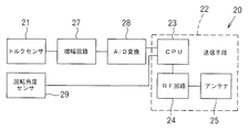
データ送信ユニット(20)は、図2に示すように、トルクセンサ(21)と、回転角度センサ(29)、トルクセンサ(21)及び回転角度センサ(29)から出力されたトルク及び/又は回転角度に関する信号を送信する送信手段(22)を主体として構成される。 As shown in FIG. 2, the data transmission unit (20) includes a torque sensor (21), torque output from the rotation angle sensor (29), torque sensor (21), and rotation angle sensor (29) and / or rotation. The transmission unit (22) that transmits a signal related to the angle is mainly configured.
トルクセンサ(21)は、回転軸(52)に作用するトルクを電気的に検知するものであり、例えば、回転軸(52)に装着される歪みゲージ(図示せず)を例示することができる。
回転軸(52)に生じたトルクの変化は、トルクセンサ(21)からトルクに関する信号として出力される。例えば、歪みゲージの場合、回転軸(52)に生じたトルクの変化は、抵抗変化として検知され、電圧変化として出力される。
The torque sensor (21) is for electrically detecting torque acting on the rotating shaft (52). For example, a strain gauge (not shown) attached to the rotating shaft (52) can be exemplified. .
The change in torque generated in the rotating shaft (52) is output from the torque sensor (21) as a signal related to torque. For example, in the case of a strain gauge, a torque change generated on the rotating shaft (52) is detected as a resistance change and output as a voltage change.
回転軸(52)が外軸と内軸から構成される場合、トルクセンサ(21)は、外軸又は内軸の何れかに装着される。なお、外軸に反力受け(53)を有する場合、反力受け(53)が配備される側の軸は、実際に締付けを行なう軸に比して作用するトルクに差が生じる場合がある。従って、この場合、実際に締付けを行なう内軸側にデータ送信ユニット(20)を取り付けることが望ましく、これにより、外軸側に取り付ける場合に比べて、より正確な締付トルクを検出することができる。 When the rotating shaft (52) is composed of an outer shaft and an inner shaft, the torque sensor (21) is mounted on either the outer shaft or the inner shaft. In addition, when the reaction force receiver (53) is provided on the outer shaft, the shaft on the side where the reaction force receiver (53) is provided may have a difference in torque acting compared to the shaft that is actually tightened. . Therefore, in this case, it is desirable to attach the data transmission unit (20) to the inner shaft side where the actual tightening is performed, so that more accurate tightening torque can be detected compared to the case where the data transmission unit (20) is mounted to the outer shaft side. it can.
回転角度センサ(29)は、回転軸(52)の回転角度を電気的に検知するものであり、例えば、回転軸(52)又は回転軸(52)と非回転部分に取り付けられるエンコーダ、ジャイロセンサ、フォトインターラプタ、又は、磁気センサを例示することができる。何れの場合も、回転角度センサ(29)は、実際に締付けを行なう軸に取り付ける。
回転軸(52)の回転角度は、回転角度センサ(29)から回転角度に関する信号として出力される。例えば、エンコーダの場合、回転軸(52)の回転角度に関する信号として、エンコーダパルスが出力される。また、ジャイロセンサの場合、絶対角速度出力が回転軸(52)の回転角度に関する信号として出力される。フォトインターラプタの場合、回転軸(52)の回転が、発光部の発した光を受光部が検知することで、デジタル信号として出力される。
The rotation angle sensor (29) is for electrically detecting the rotation angle of the rotating shaft (52). For example, the rotating shaft (52) or the encoder attached to the rotating shaft (52) and the non-rotating portion, gyro sensor A photointerrupter or a magnetic sensor can be exemplified. In either case, the rotation angle sensor (29) is attached to the shaft that is actually tightened.
The rotation angle of the rotation shaft (52) is output from the rotation angle sensor (29) as a signal relating to the rotation angle. For example, in the case of an encoder, an encoder pulse is output as a signal related to the rotation angle of the rotating shaft (52). In the case of a gyro sensor, the absolute angular velocity output is output as a signal related to the rotation angle of the rotation shaft (52). In the case of a photo interrupter, the rotation of the rotating shaft (52) is output as a digital signal when the light receiving unit detects light emitted from the light emitting unit.
トルクセンサ(21)及び回転角度センサ(29)から出力された信号は、送信手段(22)に送信される。送信手段(22)は、CPU(23)、送信用のRF(Radio Frequency)回路(24)、送信用のアンテナ(25)を含んでいる。また、ケーシング(20a)には、電源となる電池(図示せず)が搭載され、各機器に電源を供給している。 The signals output from the torque sensor (21) and the rotation angle sensor (29) are transmitted to the transmission means (22). The transmission means (22) includes a CPU (23), a transmission RF (Radio Frequency) circuit (24), and a transmission antenna (25). Further, a battery (not shown) serving as a power source is mounted on the casing (20a), and supplies power to each device.
トルクセンサ(21)と送信手段(22)のCPU(23)との間には、増幅回路(27)及びA/D変換器(28)が配備され、トルクセンサ(21)から出力されたトルクに関する信号が、増幅回路(27)にて増幅され、A/D変換器(28)にてA/D変換されて、CPU(23)に送信される。 An amplifier circuit (27) and an A / D converter (28) are arranged between the torque sensor (21) and the CPU (23) of the transmission means (22), and the torque output from the torque sensor (21). Is amplified by the amplifier circuit (27), A / D converted by the A / D converter (28), and transmitted to the CPU (23).
回転角度センサ(29)は、エンコーダのように、デジタル信号を出力する機器の場合、CPU(23)に直接信号を送信するよう接続することができる。アナログ信号を出力する機器の場合、A/D変換器(図示せず)及び必要に応じて増幅回路(図示せず)により増幅を行ない、増幅されたアナログ信号に対して、A/D変換器(図示せず)を用いてA/D変換を行ない、CPU(23)に送信する。 In the case of a device that outputs a digital signal, such as an encoder, the rotation angle sensor (29) can be connected to transmit a signal directly to the CPU (23). In the case of a device that outputs an analog signal, an A / D converter (not shown) and, if necessary, an amplifier circuit (not shown) performs amplification, and the amplified analog signal is converted into an A / D converter. A / D conversion is performed using (not shown) and transmitted to the CPU (23).
CPU(23)は、RF回路(24)からアンテナ(25)を介してトルク及び回転角度に関する信号をワイヤレス送信する。なお、アンテナ(25)がデータ送信ユニット(20)の回転によりデータ受信ユニット(30)と反対側に位置した場合に、搬送波(電波、赤外線等)が遮断されることがある。このような場合、アンテナ(25)をデータ送信ユニット(20)に所定角度毎に、複数配備することで、何れかのアンテナ(25)がデータ受信ユニット(30)側に位置できることから、搬送波が遮断されることなく確実な送信を行なうことができる。 The CPU (23) wirelessly transmits signals related to torque and rotation angle from the RF circuit (24) via the antenna (25). When the antenna (25) is positioned on the opposite side of the data receiving unit (30) due to the rotation of the data transmitting unit (20), the carrier wave (radio waves, infrared rays, etc.) may be blocked. In such a case, by arranging a plurality of antennas (25) in the data transmission unit (20) at a predetermined angle, any one of the antennas (25) can be positioned on the data reception unit (30) side. Reliable transmission can be performed without being blocked.
なお、データ送信ユニット(20)を直接回転軸(52)に配備することで、回転軸(52)に作用する締付トルクや回転軸(52)の回転角度を直接検出することができるから、回転軸(52)と動力機(モータ(54))との間に減速機構(図示せず)が配備されている締付機(50)においても、減速機構の効率の変化や弾性変形等の影響を受けることなく、正確な締付トルク及び回転軸(52)の回転角度を検出することができる。
By arranging the data transmission unit (20) directly on the rotation shaft (52), it is possible to directly detect the tightening torque acting on the rotation shaft (52) and the rotation angle of the rotation shaft (52). Even in the tightening machine (50) in which a speed reduction mechanism (not shown) is arranged between the rotating shaft (52) and the power machine (motor (54)), the effect of the speed change mechanism's efficiency change, elastic deformation, etc. Without being subjected to this, it is possible to detect the exact tightening torque and the rotation angle of the
データ送信ユニット(20)からは、電波、赤外線により信号をワイヤレスで発信することができる。また、無線LANや個人用無線ネットワーク(WPAN)を利用した構成を組むこともできる。 From the data transmission unit (20), signals can be transmitted wirelessly by radio waves and infrared rays. Further, a configuration using a wireless LAN or a personal wireless network (WPAN) can be assembled.
送信されたトルクに関する信号及び回転角度に関する信号は、図1に示すデータ受信ユニット(30)によって受信される。データ受信ユニット(30)は、後述するとおり、締付機(50)と別個に設けたり、締付機(50)にネジ等により固定した状態で取り付けることもできる。又、締付機(50)と一体に設けることもできる。 The transmitted signal relating to the torque and the signal relating to the rotation angle are received by the data receiving unit (30) shown in FIG. As will be described later, the data receiving unit (30) can be provided separately from the clamping machine (50) or can be attached to the clamping machine (50) in a state of being fixed by screws or the like. It can also be provided integrally with the tightening machine (50).
データ受信ユニット(30)は、図5に示すように、受信手段(32)として、受信用のアンテナ(35)、受信用のRF回路(34)及びCPU(33)を有する。受信されたトルクに関する信号は、アンテナ(35)及びRF回路(34)を介して、CPU(33)に送信され、トルクに関する信号をトルク値に変換したり、トルクに基づく種々の制御、記憶、管理、出力等を行なうことができる。
同様に、受信された回転角度に関する信号も、アンテナ(35)及びRF回路(34)を介して、CPU(33)に送信され、回転角度に関する信号を回転角度値に変換したり、回転角度に基づく種々の制御、記憶、管理、出力等を行なうことができる。
受信されたトルク及び回転角度に関する信号は、受信手段(32)と電気的に接続された表示手段(40)に表示することができる。これにより、受信したトルクに関する信号及び回転角度に関する信号を、トルク値や角度値として目視できる。
As shown in FIG. 5, the data receiving unit (30) includes a receiving antenna (35), a receiving RF circuit (34), and a CPU (33) as receiving means (32). The received torque-related signal is transmitted to the CPU (33) via the antenna (35) and the RF circuit (34), and the torque-related signal is converted into a torque value, and various control and storage based on the torque, Management, output, etc. can be performed.
Similarly, the received signal related to the rotation angle is also transmitted to the CPU (33) via the antenna (35) and the RF circuit (34), and the signal related to the rotation angle is converted into a rotation angle value or converted into the rotation angle. Various control, storage, management, output and the like can be performed.
The received signals relating to the torque and the rotation angle can be displayed on the display means (40) electrically connected to the receiving means (32). Thereby, the received signal relating to the torque and the signal relating to the rotation angle can be visually observed as a torque value or an angle value.
データ受信ユニット(30)への電源供給は、電池を利用することもできるし、商用電源を使用することもできる。 For the power supply to the data receiving unit (30), a battery or a commercial power source can be used.
図に、データ受信ユニット(30)の種々の実施例を示している。
図1に示すように、データ受信ユニット(30)は、締付機(50)と一体に設けることができる。なお、この場合、データ受信ユニット(30)は、締付機(50)の回転軸(52)を回転させる動力機(例えば、モータ(54))に電源を供給する電源線上に設け、動力機を制御する制御回路と受信手段(32)とを電気的に接続することが望ましい。これにより、受信手段(32)が受信したトルクに関する信号及び/又は回転角度に関する信号に基づいて、動力機(モータ(54))をフィードバック制御等することができる。
In the figure, various embodiments of the data receiving unit (30) are shown.
As shown in FIG. 1, the data receiving unit (30) can be provided integrally with the tightening machine (50). In this case, the data receiving unit (30) is provided on a power line for supplying power to a power machine (for example, the motor (54)) that rotates the rotating shaft (52) of the tightening machine (50), and controls the power machine. It is desirable to electrically connect the control circuit to the receiving means (32). Thus, feedback control of the power machine (motor (54)) can be performed based on the signal related to the torque and / or the signal related to the rotation angle received by the receiving means (32).
図3に示すように、データ受信ユニット(30)は、締付機(50)とは別個に設けることができる。この場合、表示手段(40)として、図3に示すように、液晶ディスプレイ(LCD)を例示することができ、液晶ディスプレイに測定されたトルク値及び/又は回転角度を表示させることができる。
表示手段(40)を具えたデータ受信ユニット(30)は、所望の文字の大きさ、形状のものを作製することができ、表示されるトルク値及び/又は回転角度の大きさ、色、表示時間等も適宜設定することができる。また、腕時計の如き形状としてもよい。
As shown in FIG. 3, the data receiving unit (30) can be provided separately from the tightening machine (50). In this case, as the display means (40), as shown in FIG. 3, a liquid crystal display (LCD) can be exemplified, and the measured torque value and / or rotation angle can be displayed on the liquid crystal display.
The data receiving unit (30) provided with the display means (40) can produce a desired character size and shape, and the displayed torque value and / or rotation angle size, color, display Time etc. can also be set suitably. Moreover, it is good also as a shape like a wristwatch.
表示手段(40)は、作業者が見やすい位置に固定、立て掛け、吊り下げ等を行なうことで、作業者が表示手段(40)を目視しながら、所望のトルク値及び/又は回転角度までボルト等を締め付けることができる。
表示手段(40)の電源は、データ送信ユニット(20)とは別個に配備できるから、データ送信ユニット(20)に配備される電池等を小型化、長寿命化することができる。
図4に示すように、締付機は、電動のものに限らず、手動の締付機(50)にも適用できる。この場合、表示手段(40)は、作業者が見易い位置、例えば、作業者がハンドルを握る部分から締付側のハンドル部(57)に固定することで、作業者が表示手段(40)を目視しながら入力を調節しつつ、所望のトルク値及び/又は回転角度までボルト等を締め付けることができる。
The display means (40) is fixed, stood, suspended, etc. at a position that is easy for the operator to see, so that the operator can visually observe the display means (40), and the bolts etc. to the desired torque value and / or rotation angle. Can be tightened.
Since the power source of the display means (40) can be provided separately from the data transmission unit (20), the battery or the like provided in the data transmission unit (20) can be reduced in size and extended in life.
As shown in FIG. 4, the tightening machine is not limited to an electric one but can be applied to a manual tightening machine (50). In this case, the display means (40) is fixed to the handle portion (57) on the tightening side from a position where the operator can easily see, for example, the part where the operator grips the handle, so that the operator can display the display means (40). A bolt or the like can be tightened to a desired torque value and / or rotation angle while adjusting the input while visually observing.
データ受信ユニット(30)は、図6及び図7に示すように、パソコン(42)に連繋したり、一部又は全部をパソコン(42)に内蔵する構成としてもよい。図示の例は、データ受信ユニット(30)を有線通信(37)によってパソコン(42)に連繋した実施例である。
受信されたトルクに関する信号をパソコン(42)で処理することによりトルク値に変換し、ボルト等の締付トルクをパソコン(42)に内蔵又は接続された記憶手段に記憶して管理したり、出力することができる。また、パソコン(42)のモニターを表示手段(40)として利用することもできる。さらに、トルクに関する信号及び/又は回転角度に関する信号を締付機(50)にフィードバックして、締付機(50)を制御することもできる。
As shown in FIGS. 6 and 7, the data receiving unit (30) may be connected to the personal computer (42) or may be partly or entirely built in the personal computer (42). The illustrated example is an embodiment in which the data receiving unit (30) is connected to the personal computer (42) by wired communication (37).
The received torque related signal is converted into a torque value by processing it on the personal computer (42), and the tightening torque such as bolts is stored in the storage means built in or connected to the personal computer (42) for management and output. can do. The monitor of the personal computer (42) can also be used as the display means (40). Further, a signal related to torque and / or a signal related to the rotation angle can be fed back to the tightening machine (50) to control the tightening machine (50).
なお、各締付機(50)のデータ送信ユニット(20)から送信されるトルクに関する信号及び/又は回転角度に関する信号中に、データ送信ユニット(20)の識別信号を挿入することで、図8に示すように、複数台の締付機(50)を使用する場合に、複数のデータ送信ユニット(20)と複数のデータ受信ユニット(30)を用いても、トルク値及び/又は回転角度を個々に識別して、表示、記憶等することもできる。
データ送信ユニット(20)にGPS(Global Positioning System)機能を搭載することで、例えば、橋梁等のボルト締めの際に、各ボルトが所定のトルク値及び/又は回転角度で締め付けられたことを記録、管理することもできる。また、日時を同時に記録してもよい。
さらに、受信したトルク値及び/又は回転角度をパソコン(42)でグラフ化し、締付過程を監視し、締付時に生ずる異常の有無を判別できるようにしてもよい。
In addition, by inserting the identification signal of the data transmission unit (20) into the signal regarding the torque and / or the signal regarding the rotation angle transmitted from the data transmission unit (20) of each clamping machine (50), FIG. As shown in FIG. 4, when using a plurality of tightening machines (50), the torque value and / or the rotation angle can be set even if a plurality of data transmission units (20) and a plurality of data reception units (30) are used. They can be individually identified and displayed or stored.
By installing a GPS (Global Positioning System) function in the data transmission unit (20), for example, when bolting a bridge or the like, it is recorded that each bolt has been tightened with a predetermined torque value and / or rotation angle. Can also manage. Further, the date and time may be recorded simultaneously.
Further, the received torque value and / or rotation angle may be graphed by a personal computer (42), and the tightening process may be monitored to determine whether there is an abnormality occurring during tightening.
データ受信ユニット(30)を、図9及び図10に示すように、締付機(50)のグリップ部(56)等に直接取り付けて、締付トルク値及び/又は回転角度を目視したり、締付機(50)の動力機となるモータ(54)を、受信されたトルク値及び/又は回転角度に基づいて制御することができる。
一例として、図9に示すように、締付機(50)に表示手段(40)及び所望の締付トルク及び/又は回転角度を設定するスイッチ(58)を配備し、図10に示すように、データ受信ユニット(30)のCPU(33)に表示手段(40)及び設定スイッチ(58)を連繋し、さらに、締付機(50)のモータ(54)に電力を供給するモータ制御回路(44)とCPU(33)をD/A変換器(46)を介して接続した構成を挙げることができる。
As shown in FIGS. 9 and 10, the data receiving unit (30) is directly attached to the grip part (56) of the tightening machine (50), and the tightening torque value and / or the rotation angle is visually observed. The motor (54) serving as the power machine of the tightening machine (50) can be controlled based on the received torque value and / or rotation angle.
As an example, as shown in FIG. 9, a display means (40) and a switch (58) for setting a desired tightening torque and / or rotation angle are provided in the tightening machine (50), and as shown in FIG. A motor control circuit (not shown) that connects the display means (40) and the setting switch (58) to the CPU (33) of the data receiving unit (30), and supplies power to the motor (54) of the clamping machine (50). 44) and a CPU (33) may be connected via a D / A converter (46).
また、予め、設定スイッチ(58)により、所望の締付トルク又は回転角度を入力しておくことで、受信したトルク値が、所望の締付トルク又は回転角度に達したときに、CPU(33)からモータ制御回路(44)にモータ(54)への通電を遮断したり、所望の締付トルク又は回転角度に近づいたときに、モータ(54)への供給電力を下げて減速させる制御をすることができる。この場合、表示手段(40)に入力したトルク値及び/又は回転角度を表示させるようにしてもよい。
上記によれば、回転軸(52)から直接締付トルクを検知して、モータ(54)を制御できるから、モータの負荷検知により締付トルクを制御するよりも、正確な締付トルクで締付を行なうことができる。
Further, by inputting a desired tightening torque or rotation angle in advance by the setting switch (58), when the received torque value reaches the desired tightening torque or rotation angle, the CPU (33 ) From the motor control circuit (44) to the motor (54), or when the motor approaches the desired tightening torque or rotation angle, the power supplied to the motor (54) is reduced to reduce the speed. can do. In this case, the torque value and / or rotation angle input to the display means (40) may be displayed.
According to the above, since the tightening torque can be detected directly from the rotating shaft (52) and the motor (54) can be controlled, the tightening torque can be tightened more accurately than when the tightening torque is controlled by detecting the motor load. Attaching can be performed.
図11は、本発明を、薄型のレンチ(60)を取り付けた締付機(50)に適用した実施例である。薄型レンチ(60)は、締付機(50)のソケット(59)の回転中心とは異なる位置に締付用ソケット(62)を有している。ソケット(59)と締付用ソケット(62)は、ギア機構(64)により連繋されている。
データ送信ユニット(20)は、レンチ(60)の内部に配備され、データ受信ユニット(30)は、締付機(50)側に取り付けられている。
本構成のレンチ(60)を具えた締付機(50)は、締付けの際に、締付トルクがデータ送信ユニット(20)からデータ受信ユニット(30)にワイヤレス送信され、締付トルク及び/又は回転角度を締付機(50)側の表示手段(40)にて目視したり、締付機(50)の動力機となるモータ(54)を受信されたトルク値及び/又は回転角度に基づいて制御することができる。
FIG. 11 shows an embodiment in which the present invention is applied to a tightening machine (50) to which a thin wrench (60) is attached. The thin wrench (60) has a fastening socket (62) at a position different from the rotation center of the socket (59) of the fastening machine (50). The socket (59) and the fastening socket (62) are connected by a gear mechanism (64).
The data transmission unit (20) is disposed inside the wrench (60), and the data reception unit (30) is attached to the tightening machine (50) side.
In the tightening machine (50) having the wrench (60) of this configuration, when tightening, the tightening torque is transmitted wirelessly from the data transmission unit (20) to the data reception unit (30), and the tightening torque and / or Alternatively, the rotation angle is visually observed on the display means (40) on the side of the tightening machine (50), or the motor (54) serving as the power machine of the tightening machine (50) is received based on the received torque value and / or rotation angle. Can be controlled.
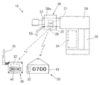
図12は、本発明を、手動式のレンチ(51)と増力器(70)からなる締付機(50)に適用した実施例である。増力器(70)は、遊星歯車機構(72)を有しており、先端外筒(74)に反力受け(76)が配備されている。
データ送信ユニット(20)は、増力器(70)の内部に配備され、データ受信ユニット(30)は、レンチ(51)のハンドル部(57)に取り付けられている。
本構成のレンチ(51)は、使用者がハンドル部(57)を掴んで、手動によりボルト等の締付けを行なうことで、締付トルクがデータ送信ユニット(20)からデータ受信ユニット(30)にワイヤレス送信され、締付トルクをハンドル部(57)の表示手段(70)にて目視することができる。
FIG. 12 shows an embodiment in which the present invention is applied to a clamping machine (50) comprising a manual wrench (51) and a booster (70). The intensifier (70) has a planetary gear mechanism (72), and a reaction force receiver (76) is provided on the distal end outer cylinder (74).
The data transmission unit (20) is disposed inside the intensifier (70), and the data reception unit (30) is attached to the handle portion (57) of the wrench (51).
The wrench (51) with this configuration allows the user to grip the handle (57) and manually tighten bolts, etc., so that the tightening torque is transferred from the data transmission unit (20) to the data reception unit (30). Wirelessly transmitted and the tightening torque can be visually observed on the display means (70) of the handle portion (57).
上記実施例では、動力機としてモータ(54)を例示しているが、動力機は、電気式のものに限らず、空気圧式、油圧式のものを用いることもできる。 In the above embodiment, the motor (54) is exemplified as the power machine, but the power machine is not limited to an electric type, and a pneumatic type or a hydraulic type can also be used.
本発明は、締付機の回転軸から直接締付トルク及び/又は回転軸の回転角度を検出してワイヤレスで送受信し、締付機にフィードバックしたり、パソコン等に送信し、種々の制御等を行なうことができるワイヤレス・データ送受信システムとして有用である。 The present invention detects the tightening torque and / or rotation angle of the rotating shaft directly from the rotating shaft of the tightening machine, wirelessly transmits and receives it, feeds it back to the tightening machine, transmits it to a personal computer, etc. It is useful as a wireless data transmission / reception system capable of performing
(10) ワイヤレス・データ送受信システム
(20) データ送信ユニット
(21) トルクセンサ
(22) 送信手段
(29) 回転角度センサ
(30) データ受信ユニット
(32) 受信手段
(40) 表示手段
(42) パソコン
(50) 締付機
(52) 回転軸
(10) Wireless data transmission / reception system
(20) Data transmission unit
(21) Torque sensor
(22) Transmission method
(29) Rotation angle sensor
(30) Data reception unit
(32) Receiving means
(40) Display means
(42) PC
(50) Tightening machine
(52) Rotating shaft
Claims (13)
前記データ送信ユニットの送信手段から送信されたトルクに関する信号を受信する受信手段と、該受信手段が受信したトルクに関する信号を表示する表示手段と、を有するデータ受信ユニットと、
を具備していることを特徴とするワイヤレス・データ送受信システム。 A data transmission unit provided on the inner shaft of a clamping machine having a rotating shaft composed of an inner shaft and an outer shaft that can rotate in opposite directions, and having a function of detecting torque, which acts on the inner shaft A data transmission unit comprising: a torque sensor arranged to detect torque; and a transmission unit that is electrically connected to the torque sensor and wirelessly transmits a signal related to the torque detected by the torque sensor;
A data receiving unit having receiving means for receiving a signal related to torque transmitted from the transmitting means of the data transmitting unit; and display means for displaying a signal related to torque received by the receiving means;
A wireless data transmission / reception system comprising:
前記データ送信ユニットの送信手段から送信された回転角度に関する信号を受信する受信手段と、該受信手段が受信した回転角度に関する信号を表示する表示手段と、を有するデータ受信ユニットと、
を具備していることを特徴とするワイヤレス・データ送受信システム。 A data transmission unit provided on the inner shaft of a clamping machine having a rotation shaft composed of an inner shaft and an outer shaft that can rotate in opposite directions, and having a function of detecting a rotation angle, the rotation of the inner shaft A data transmission unit comprising: a rotation angle sensor arranged to detect an angle; and a transmission unit that is electrically connected to the rotation angle sensor and wirelessly transmits a signal related to the rotation angle detected by the rotation angle sensor; ,
A data receiving unit comprising: a receiving unit that receives a signal related to the rotation angle transmitted from the transmitting unit of the data transmission unit; and a display unit that displays a signal related to the rotation angle received by the receiving unit;
A wireless data transmission / reception system comprising:
前記データ送信ユニットの送信手段から送信されたトルク及び回転角度に関する信号を受信する受信手段と、該受信手段が受信したトルク及び回転角度に関する信号を表示する表示手段と、を有するデータ受信ユニットと、
を具備していることを特徴とするワイヤレス・データ送受信システム。 Provided on the inner shaft of the tightening machine having a rotating shaft comprised of an inner shaft and the outer shaft rotatable in opposite directions, a data transmission unit which has a function of detecting the torque and rotational angle, the inner shaft A torque sensor arranged to detect torque acting on the rotation shaft, a rotation angle sensor arranged to detect the rotation angle of the inner shaft, and electrically connected to the torque sensor and the rotation angle sensor. A transmission means for wirelessly transmitting a signal relating to the detected torque and the rotation angle detected by the rotation angle sensor;
A data receiving unit having receiving means for receiving a signal related to torque and rotation angle transmitted from the transmitting means of the data transmission unit; and a display means for displaying a signal related to torque and rotation angle received by the receiving means;
A wireless data transmission / reception system comprising:
The wireless data transmission / reception system according to any one of claims 2 to 11 , wherein the rotation angle sensor is an encoder, a gyro sensor, a photo interrupter, or a magnetic sensor.
Priority Applications (10)
| Application Number | Priority Date | Filing Date | Title |
|---|---|---|---|
| JP2009099764A JP5431006B2 (en) | 2009-04-16 | 2009-04-16 | Wireless data transmission / reception system |
| ES10159924T ES2703763T3 (en) | 2009-04-16 | 2010-04-14 | Wireless system of transmission and reception of data |
| EP10159924.9A EP2248632B1 (en) | 2009-04-16 | 2010-04-14 | Wireless data transmitting and receiving system |
| TW099111623A TWI495274B (en) | 2009-04-16 | 2010-04-14 | Wireless data transmitting and receiving system |
| PL10159924T PL2248632T3 (en) | 2009-04-16 | 2010-04-14 | Wireless data transmitting and receiving system |
| US12/759,819 US8264374B2 (en) | 2009-04-16 | 2010-04-14 | Wireless data transmitting and receiving system |
| KR1020100034844A KR101692073B1 (en) | 2009-04-16 | 2010-04-15 | Wireless data transmitting and receiving system |
| CN201010228946.5A CN101890691B (en) | 2009-04-16 | 2010-04-15 | Wireless data transmitting and receiving system |
| CA2700038A CA2700038C (en) | 2009-04-16 | 2010-04-15 | Wireless data transmitting and receiving system |
| HK11100912.2A HK1146815A1 (en) | 2009-04-16 | 2011-01-28 | Wireless data transmitting and receiving system |
Applications Claiming Priority (1)
| Application Number | Priority Date | Filing Date | Title |
|---|---|---|---|
| JP2009099764A JP5431006B2 (en) | 2009-04-16 | 2009-04-16 | Wireless data transmission / reception system |
Publications (3)
| Publication Number | Publication Date |
|---|---|
| JP2010247277A JP2010247277A (en) | 2010-11-04 |
| JP2010247277A5 JP2010247277A5 (en) | 2012-03-01 |
| JP5431006B2 true JP5431006B2 (en) | 2014-03-05 |
Family
ID=42200932
Family Applications (1)
| Application Number | Title | Priority Date | Filing Date |
|---|---|---|---|
| JP2009099764A Active JP5431006B2 (en) | 2009-04-16 | 2009-04-16 | Wireless data transmission / reception system |
Country Status (10)
| Country | Link |
|---|---|
| US (1) | US8264374B2 (en) |
| EP (1) | EP2248632B1 (en) |
| JP (1) | JP5431006B2 (en) |
| KR (1) | KR101692073B1 (en) |
| CN (1) | CN101890691B (en) |
| CA (1) | CA2700038C (en) |
| ES (1) | ES2703763T3 (en) |
| HK (1) | HK1146815A1 (en) |
| PL (1) | PL2248632T3 (en) |
| TW (1) | TWI495274B (en) |
Families Citing this family (117)
| Publication number | Priority date | Publication date | Assignee | Title |
|---|---|---|---|---|
| SE533830C2 (en) * | 2009-06-11 | 2011-02-01 | Atlas Copco Tools Ab | Nut wrench with gearbox and parameter transducer |
| TWM392713U (en) * | 2010-07-12 | 2010-11-21 | Legend Lifestyle Products Corp | Wireless torque wrench with angle correction feature |
| CN102528721B (en) * | 2010-12-29 | 2017-03-01 | 罗伯特·博世有限公司 | Have the wireless radio transmission of minimizing data bulk accumulator run screw system |
| DE102010056524B4 (en) * | 2010-12-29 | 2019-11-28 | Robert Bosch Gmbh | Portable tool and method for performing operations with this tool |
| TWI435795B (en) * | 2011-03-28 | 2014-05-01 | China Pneumatic Corp | System and method for displaying torque |
| CN102706503B (en) * | 2011-03-28 | 2013-12-25 | 中国气动工业股份有限公司 | Torque display system and method thereof |
| CN102297739B (en) * | 2011-05-27 | 2012-12-26 | 杨俊志 | System for monitoring anchored force of pre-stressed anchor cable in real time |
| ITMO20110153A1 (en) * | 2011-06-17 | 2012-12-18 | Dino Paoli S R L | IMPACT TOOL |
| ITMO20110154A1 (en) * | 2011-06-17 | 2012-12-18 | Dino Paoli S R L | IMPACT TOOL |
| EP2535139B1 (en) | 2011-06-17 | 2016-04-06 | Dino Paoli S.r.l. | Impact tool |
| DE102011105306A1 (en) * | 2011-06-22 | 2012-12-27 | Robert Bosch Gmbh | Portable tool with wireless data transmission |
| JP5853191B2 (en) * | 2011-09-20 | 2016-02-09 | パナソニックIpマネジメント株式会社 | Electric tool |
| US9272799B2 (en) | 2011-10-04 | 2016-03-01 | Signode Industrial Group Llc | Sealing tool for strap |
| ITMO20110287A1 (en) * | 2011-11-11 | 2013-05-12 | Dino Paoli S R L | COUNTS CYCLES |
| DE102012200819A1 (en) * | 2012-01-20 | 2013-07-25 | Robert Bosch Gmbh | Method with a hand tool and a mobile computer |
| CN103223655B (en) * | 2012-01-27 | 2017-04-12 | 英格索尔-兰德公司 | A precision-fastening handheld cordless power tool |
| US9281770B2 (en) | 2012-01-27 | 2016-03-08 | Ingersoll-Rand Company | Precision-fastening handheld cordless power tools |
| DE102012221997A1 (en) | 2012-05-25 | 2013-11-28 | Robert Bosch Gmbh | power tool |
| US8413525B1 (en) * | 2012-06-11 | 2013-04-09 | Thru Tubing Solutions, Inc. | Portable torque measurement and notification system and method of using same |
| US8528423B1 (en) * | 2012-06-11 | 2013-09-10 | Thru Tubing Solutions, Inc. | Portable torque measurement and notification system and method of using same |
| DE102012017376A1 (en) * | 2012-06-13 | 2013-12-19 | Robert Bosch Gmbh | Electrical propelled tool i.e. rechargeable battery-claimant screw jack, has tool components provided with power supply unit that enables data communication unit to generate power using inductive coupling |
| TW201411107A (en) * | 2012-09-12 | 2014-03-16 | wen-hui Liao | Non-contact type torque measurement method and measurement method thereof |
| JP6008319B2 (en) * | 2012-10-12 | 2016-10-19 | パナソニックIpマネジメント株式会社 | Impact rotary tool |
| WO2014065066A1 (en) * | 2012-10-26 | 2014-05-01 | Totsu Katsuyuki | Automatic screw tightening control method and device |
| US9367062B2 (en) * | 2012-12-31 | 2016-06-14 | Robert Bosch Gmbh | System and method for operational data retrieval from a power tool |
| DE102013202383A1 (en) * | 2013-02-14 | 2014-08-14 | Schaeffler Technologies Gmbh & Co. Kg | Torque measuring device |
| ITMI20130495A1 (en) * | 2013-03-29 | 2014-09-30 | Atlas Copco Blm Srl | ELECTRONIC CONTROL AND CONTROL DEVICE FOR SENSORS |
| FR3004132B1 (en) * | 2013-04-03 | 2019-06-21 | Sam Outillage | DYNAMOMETRIC CLAMP ASSEMBLY |
| CN103267605B (en) * | 2013-05-17 | 2015-10-28 | 大连民族学院 | A kind of electric wrench torsion angle detection system and method |
| US20150033917A1 (en) * | 2013-08-05 | 2015-02-05 | Xuan-Ren Chen | Torque Multiplier |
| WO2015061370A1 (en) | 2013-10-21 | 2015-04-30 | Milwaukee Electric Tool Corporation | Adapter for power tool devices |
| JP2015085470A (en) * | 2013-10-31 | 2015-05-07 | Tone株式会社 | Fastening/loosening device and method for controlling the same |
| JP6322387B2 (en) * | 2013-11-05 | 2018-05-09 | Tone株式会社 | Fastening device and fastening method |
| TWM478149U (en) * | 2013-12-17 | 2014-05-11 | Matatakitoyo Tool Co Ltd | Wireless transmission type connecting rod |
| CA2918107C (en) * | 2013-12-26 | 2017-11-14 | Suzhou Tergar Iot Technology Co., Ltd | Center-mounted control system of bicycle |
| US9700978B2 (en) | 2014-01-27 | 2017-07-11 | The Boeing Company | System and method for processing a workpiece |
| CN103825213A (en) * | 2014-03-04 | 2014-05-28 | 东南大学 | Remote control intelligent bolt fastening device and method for same |
| US20150336248A1 (en) * | 2014-05-20 | 2015-11-26 | Kevin Goe | Power Drill Having Torque Setting Mechanism |
| WO2016062915A1 (en) * | 2014-10-23 | 2016-04-28 | Jukka Jokinen | Method for tightening a high-pressure pipe connection to a correct tightness and a device for carrying out the method |
| CN107407925B (en) * | 2014-12-15 | 2019-08-20 | 艾沛克斯品牌公司 | Convertible intelligent power tool |
| DE102015000555A1 (en) | 2015-01-20 | 2016-07-21 | Frank Hohmann | Screwdrivers |
| DE102015204795A1 (en) * | 2015-03-17 | 2016-09-22 | Robert Bosch Gmbh | Device with display means and method for providing device information |
| KR200489917Y1 (en) | 2015-04-28 | 2019-08-28 | 밀워키 일렉트릭 툴 코포레이션 | Precision Torque Screwdriver |
| US10357871B2 (en) | 2015-04-28 | 2019-07-23 | Milwaukee Electric Tool Corporation | Precision torque screwdriver |
| US10603770B2 (en) | 2015-05-04 | 2020-03-31 | Milwaukee Electric Tool Corporation | Adaptive impact blow detection |
| CN110213676B (en) | 2015-05-04 | 2022-08-19 | 米沃奇电动工具公司 | Electric tool and wireless communication method |
| US10295990B2 (en) | 2015-05-18 | 2019-05-21 | Milwaukee Electric Tool Corporation | User interface for tool configuration and data capture |
| EP3302883B1 (en) | 2015-06-02 | 2022-03-16 | Milwaukee Electric Tool Corporation | Multi-speed power tool with electronic clutch |
| WO2016203315A2 (en) | 2015-06-15 | 2016-12-22 | Milwaukee Electric Tool Corporation | Power tool communication system |
| US10618151B2 (en) | 2015-06-15 | 2020-04-14 | Milwaukee Electric Tool Corporation | Hydraulic crimper tool |
| US10380883B2 (en) | 2015-06-16 | 2019-08-13 | Milwaukee Electric Tool Corporation | Power tool profile sharing and permissions |
| US20170014984A1 (en) * | 2015-07-16 | 2017-01-19 | Apex Brands, Inc. | High-power lightweight tool |
| CN105070025A (en) * | 2015-09-10 | 2015-11-18 | 南通大学 | Wireless torque monitoring system for industrial use |
| US10345797B2 (en) | 2015-09-18 | 2019-07-09 | Milwaukee Electric Tool Corporation | Power tool operation recording and playback |
| WO2017075129A1 (en) * | 2015-10-28 | 2017-05-04 | Ultra Clean Technology | Precision connections and methods of forming same |
| NZ742034A (en) | 2015-10-30 | 2019-04-26 | Milwaukee Electric Tool Corp | Remote light control, configuration, and monitoring |
| US11424601B2 (en) | 2015-11-02 | 2022-08-23 | Milwaukee Electric Tool Corporation | Externally configurable worksite power distribution box |
| US10577137B2 (en) | 2015-12-09 | 2020-03-03 | Signode Industrial Group Llc | Electrically powered combination hand-held notch-type strapping tool |
| EP3389929B1 (en) * | 2015-12-16 | 2022-11-02 | Atlas Copco Industrial Technique AB | A system for pre-tensioning a joint comprising a number of threaded elements |
| TWI671170B (en) | 2015-12-17 | 2019-09-11 | 美商米沃奇電子工具公司 | System and method for configuring a power tool with an impact mechanism |
| WO2017120165A1 (en) | 2016-01-05 | 2017-07-13 | Milwaukee Electric Tool Corporation | Vibration reduction system and method for power tools |
| US20170201853A1 (en) * | 2016-01-09 | 2017-07-13 | Chervon (Hk) Limited | Power tool system |
| EP3919244A1 (en) | 2016-02-03 | 2021-12-08 | Milwaukee Electric Tool Corporation | System and methods for configuring a reciprocating saw |
| WO2017147437A1 (en) | 2016-02-25 | 2017-08-31 | Milwaukee Electric Tool Corporation | Power tool including an output position sensor |
| TWI622466B (en) * | 2016-03-29 | 2018-05-01 | Nitto Kohki Co., Ltd. | Control circuit, power tool, control device and power tool system for electric tool with setting data transmission function |
| TWI579112B (en) * | 2016-04-08 | 2017-04-21 | 國立高雄應用科技大學 | A torque measurement for rotating tool |
| DE102016206050A1 (en) * | 2016-04-12 | 2017-10-12 | Robert Bosch Gmbh | Hand tool with an electronic torque limiting unit |
| US11622392B2 (en) | 2016-06-06 | 2023-04-04 | Milwaukee Electric Tool Corporation | System and method for establishing a wireless connection between power tool and mobile device |
| TWM555274U (en) | 2016-06-06 | 2018-02-11 | 米沃奇電子工具公司 | Mobile devices for connecting with power tool devices |
| US10309855B2 (en) | 2016-08-23 | 2019-06-04 | FUTEK Advanced Sensor Technology | Torque sensing system with wireless two-way communication |
| CN106393009A (en) * | 2016-08-30 | 2017-02-15 | 常州格力博有限公司 | Electric tool |
| KR102191641B1 (en) * | 2016-11-10 | 2020-12-16 | 니토 코키 가부시키가이샤 | Electric Motor-Driven Tool, and Control Device and Control Circuit Therefor |
| CN106323518A (en) * | 2016-11-14 | 2017-01-11 | 苏州卡迪姆电子科技有限公司 | Dynamic torque sensing device |
| CN110072670B (en) * | 2016-12-15 | 2020-12-25 | 阿特拉斯·科普柯工业技术公司 | Method for monitoring energy flow in a tightening tool, monitoring node and computer-readable storage medium |
| WO2018123816A1 (en) * | 2016-12-26 | 2018-07-05 | 京都機械工具株式会社 | Torque value setting system, torque value setting device, and torque value setting method |
| KR101879236B1 (en) * | 2017-03-31 | 2018-07-17 | 주식회사 노아 엑츄에이션 | Torque measuring apparatus |
| TWI619582B (en) * | 2017-06-09 | 2018-04-01 | China Pneumatic Corp | Torque control system of electric impact type torque tool and torque control method thereof |
| US10940577B2 (en) | 2017-07-19 | 2021-03-09 | China Pneumatic Corporation | Torque control system and torque control method for power impact torque tool |
| EP3664970A4 (en) * | 2017-08-07 | 2021-08-04 | Milwaukee Electric Tool Corporation | Power tool with irreversably lockable compartment |
| JP6964870B2 (en) | 2017-08-29 | 2021-11-10 | 京都機械工具株式会社 | Tightening tool |
| JP6982851B2 (en) * | 2017-08-29 | 2021-12-17 | 京都機械工具株式会社 | Tightening work analysis device, tightening work analysis system, tightening work analysis program, tightening work analysis method, tightening tool |
| KR101814678B1 (en) * | 2017-08-31 | 2018-01-03 | (주)효진산업 | A hydraulic wrench system provided on a workbench |
| KR101814681B1 (en) * | 2017-08-31 | 2018-01-03 | (주)효진산업 | Handy hydraulic wrench |
| KR101915410B1 (en) | 2017-08-31 | 2018-11-05 | 형우생 | Hydraulic wrench for easy replacement of socket |
| US10926368B2 (en) * | 2017-09-27 | 2021-02-23 | Ingersoll-Rand Industrial U.S., Inc. | Part illumination status lights |
| US11260514B2 (en) | 2017-11-29 | 2022-03-01 | Milwaukee Electric Tool Corporation | Externally attachable tracking module for a power tool |
| US20190217460A1 (en) * | 2018-01-18 | 2019-07-18 | Ingersoll-Rand Company | Add-on user interface module for precision power tools |
| US20190232471A1 (en) * | 2018-02-01 | 2019-08-01 | Dino Paoli S.R.L. | Impact tool |
| TWI657899B (en) * | 2018-02-26 | 2019-05-01 | 車王電子股份有限公司 | Electrical tools |
| US11752604B2 (en) * | 2018-04-13 | 2023-09-12 | Snap-On Incorporated | System and method for measuring torque and angle |
| US10341025B1 (en) | 2018-05-01 | 2019-07-02 | FUTEK Advanced Sensor Technology | Optical data system for torque sensor |
| CN108688765A (en) * | 2018-05-07 | 2018-10-23 | 重庆三叶花科技有限公司 | The method for transmitting signals of axis moment measuring device |
| CN108609102A (en) * | 2018-05-07 | 2018-10-02 | 重庆三叶花科技有限公司 | Signal transmission system for axis moment measuring device |
| JP7249558B2 (en) * | 2018-09-07 | 2023-03-31 | パナソニックIpマネジメント株式会社 | power tools and processing equipment |
| JP7436466B2 (en) * | 2018-09-21 | 2024-02-21 | アトラス・コプコ・インダストリアル・テクニーク・アクチボラグ | electric pulse tools |
| TWI666094B (en) * | 2018-10-04 | 2019-07-21 | 詹鎔穗 | Torque wrench structure |
| JP7038378B2 (en) | 2018-10-25 | 2022-03-18 | Tone株式会社 | Electric tool |
| WO2020163450A1 (en) | 2019-02-06 | 2020-08-13 | Milwaukee Electric Tool Corporation | Power tool with shared terminal block |
| CN110995296B (en) * | 2019-02-21 | 2021-03-23 | 上海光古电子有限公司 | Short wave ultrashort wave full-automatic reconnaissance recognition receiver |
| WO2020217378A1 (en) * | 2019-04-25 | 2020-10-29 | 京セラ株式会社 | Communication device, control method, and control program |
| BR102019012058A2 (en) * | 2019-06-13 | 2020-12-22 | M3 Health Ind E Comercio De Produtos Medicos Odontologicos E Correlatos S A | electronic torque wrench capable of measuring and sending reading data via wireless interface |
| EP3756827A1 (en) * | 2019-06-27 | 2020-12-30 | Hilti Aktiengesellschaft | Machine tool and method for operating a machine tool |
| CN112785827B (en) * | 2019-11-06 | 2023-09-19 | 沈阳新松机器人自动化股份有限公司 | Antenna angle control system and method based on network communication technology |
| TWI712467B (en) * | 2019-11-08 | 2020-12-11 | 國立勤益科技大學 | Intelligent data sensing and torque analysis dynamic data link cloud numerical analysis and timely feedback system |
| JP7420936B2 (en) | 2019-11-21 | 2024-01-23 | ミルウォーキー エレクトリック ツール コーポレイション | Insertable wireless communication device for power tools |
| TWI714367B (en) * | 2019-11-26 | 2020-12-21 | 炬岱企業有限公司 | Torque detection method of electric hydraulic pulse tool |
| CN113458766B (en) * | 2020-03-30 | 2022-10-18 | 广州汽车集团股份有限公司 | Bolt tightening device |
| CN112936156B (en) * | 2020-04-14 | 2024-04-16 | 河南牛帕力学工程研究院 | Spanner |
| TWI732586B (en) * | 2020-06-08 | 2021-07-01 | 中華學校財團法人中華科技大學 | Detection device of electrical tools |
| CA3128650A1 (en) * | 2020-08-31 | 2022-02-28 | Snap-On Incorporated | Wireless torque wrench with torque specificaitons |
| CN112038869B (en) * | 2020-09-08 | 2021-10-15 | 江西应用技术职业学院 | Cooperative robot interface self-rotating type connecting line access device |
| TWI794012B (en) * | 2021-03-18 | 2023-02-21 | 賴士豪 | Torque wrench |
| EP4279216A1 (en) * | 2022-05-20 | 2023-11-22 | Hilti Aktiengesellschaft | A method for monitoring a pressing or crimping process |
| CN115291644A (en) * | 2022-07-09 | 2022-11-04 | 上海优拜机械股份有限公司 | Torque wrench control method and system |
| WO2024059031A1 (en) * | 2022-09-13 | 2024-03-21 | Apex Brands, Inc. | Wireless clutch sensor |
| EP4353418A1 (en) * | 2022-10-14 | 2024-04-17 | Matatakitoyo Tool Co., Ltd. | Torque sensing arrangement of power tool |
| SE545829C2 (en) * | 2022-10-20 | 2024-02-13 | Atlas Copco Ind Technique Ab | Control device and method for determining a joint identity of a tightened joint |
Family Cites Families (14)
| Publication number | Priority date | Publication date | Assignee | Title |
|---|---|---|---|---|
| DE4210201A1 (en) * | 1992-03-28 | 1993-09-30 | Gardner Denver Gmbh | Compressed air screwdriver tool - has drive motor arranged in housing and connected to compressed air source across air line connected to handle for driving shaft with screwing tool bit and measurement value pick-up at driven shaft |
| DE4307131C2 (en) | 1993-03-06 | 1995-11-16 | Albert Kipfelsberger | Power wrench with electronic torque limitation |
| EP0651239A3 (en) * | 1993-10-29 | 1996-06-12 | Omron Tateisi Electronics Co | Magnetostrictive torque sensor, magnetostrictive torque measuring apparatus, and condition - monitoring apparatus for a cutting tool using the same. |
| JPH10329051A (en) * | 1997-05-23 | 1998-12-15 | Yaskawa Electric Corp | Screw tightening machine and control method therefor |
| DE19846947A1 (en) * | 1998-10-12 | 2000-04-13 | Zahnradfabrik Friedrichshafen | A compressed air driven screwdriver has sensors to indicate that the preset torque value has been reached. |
| DE19961374A1 (en) | 1999-12-20 | 2001-06-21 | Volkswagen Ag | Device to form screw connections; has external data processing and memory unit to provide screwing parameter and measuring units to measure parameter after screwing for transmission to data unit |
| DE10137896A1 (en) * | 2001-08-02 | 2003-02-20 | Paul-Heinz Wagner | Method for tightening screws with power screwdriver prevents damage to screws and provides a high measure of accuracy and reproducibility in the screwing process |
| JP4429616B2 (en) * | 2003-03-24 | 2010-03-10 | 株式会社マキタ | Power tool |
| EP1439035A1 (en) * | 2002-12-16 | 2004-07-21 | Fast Technology AG | Signal processing and control device for a power torque tool |
| JP4394983B2 (en) * | 2004-03-16 | 2010-01-06 | 株式会社東日製作所 | Tightening torque measuring instrument tester |
| JP3975299B2 (en) * | 2004-07-08 | 2007-09-12 | 前田金属工業株式会社 | Tightening torque measuring unit and torque display tightening machine |
| CN2730563Y (en) * | 2004-09-17 | 2005-10-05 | 沈阳黎明航空发动机(集团)有限责任公司 | Wireless transmission sensoring type large moment wrench for speed reducer |
| DE202007002793U1 (en) * | 2007-02-22 | 2007-05-10 | Eduard Wille Gmbh & Co. Kg | Electronic tightening angle measuring device for electronic torque spanner, has rotation angle measuring sensor for measurement of angle, and memory for digital storage of measured angle data, where device is detachably attached at spanner |
| JP2008213085A (en) * | 2007-03-02 | 2008-09-18 | Matsushita Electric Works Ltd | Power tool control system |
-
2009
- 2009-04-16 JP JP2009099764A patent/JP5431006B2/en active Active
-
2010
- 2010-04-14 EP EP10159924.9A patent/EP2248632B1/en active Active
- 2010-04-14 PL PL10159924T patent/PL2248632T3/en unknown
- 2010-04-14 TW TW099111623A patent/TWI495274B/en active
- 2010-04-14 ES ES10159924T patent/ES2703763T3/en active Active
- 2010-04-14 US US12/759,819 patent/US8264374B2/en active Active
- 2010-04-15 KR KR1020100034844A patent/KR101692073B1/en active IP Right Grant
- 2010-04-15 CA CA2700038A patent/CA2700038C/en active Active
- 2010-04-15 CN CN201010228946.5A patent/CN101890691B/en active Active
-
2011
- 2011-01-28 HK HK11100912.2A patent/HK1146815A1/en unknown
Also Published As
| Publication number | Publication date |
|---|---|
| KR20100114850A (en) | 2010-10-26 |
| CN101890691A (en) | 2010-11-24 |
| EP2248632A1 (en) | 2010-11-10 |
| TW201131995A (en) | 2011-09-16 |
| US20100265097A1 (en) | 2010-10-21 |
| CN101890691B (en) | 2014-11-19 |
| KR101692073B1 (en) | 2017-01-02 |
| PL2248632T3 (en) | 2019-04-30 |
| CA2700038C (en) | 2016-09-20 |
| ES2703763T3 (en) | 2019-03-12 |
| TWI495274B (en) | 2015-08-01 |
| HK1146815A1 (en) | 2011-07-15 |
| EP2248632B1 (en) | 2018-10-17 |
| US8264374B2 (en) | 2012-09-11 |
| JP2010247277A (en) | 2010-11-04 |
| CA2700038A1 (en) | 2010-10-16 |
Similar Documents
| Publication | Publication Date | Title |
|---|---|---|
| JP5431006B2 (en) | Wireless data transmission / reception system | |
| US11766770B2 (en) | Powered ratcheting torque wrench | |
| EP1614506B1 (en) | Tightening torque measuring unit and torque indicating tightening device | |
| US7841100B2 (en) | Angle measuring device | |
| KR102433312B1 (en) | power tools | |
| EP2440372B1 (en) | Portable power wrench with a gear casing and a parameter sensing device | |
| EP2800959B1 (en) | Assembly, intercalated between a torque tool and a fastening element, for measuring torques and tightening angles | |
| EP3484662A1 (en) | Powered ratcheting torque wrench | |
| US11453105B2 (en) | Powered ratcheting torque wrench | |
| AU2023201362A1 (en) | System and method for measuring torque and angle | |
| JP2010517798A (en) | Power wrench with swivel gear casing | |
| CN104708298A (en) | Wireless transmission type extension rod | |
| JP2017087318A (en) | Fastening data management system | |
| CN210361096U (en) | Power tool | |
| KR102059597B1 (en) | Self charging type wireless torque device and system thereof | |
| US20230052650A1 (en) | System for chip-removing machining of a workpiece and for measuring and evaluating force and torque during chip-removing machining of the workpiece | |
| US20220395967A1 (en) | Powered ratcheting torque wrench |
Legal Events
| Date | Code | Title | Description |
|---|---|---|---|
| A521 | Written amendment |
Free format text: JAPANESE INTERMEDIATE CODE: A523 Effective date: 20120116 |
|
| A621 | Written request for application examination |
Free format text: JAPANESE INTERMEDIATE CODE: A621 Effective date: 20120116 |
|
| A131 | Notification of reasons for refusal |
Free format text: JAPANESE INTERMEDIATE CODE: A131 Effective date: 20130528 |
|
| A977 | Report on retrieval |
Free format text: JAPANESE INTERMEDIATE CODE: A971007 Effective date: 20130531 |
|
| A521 | Written amendment |
Free format text: JAPANESE INTERMEDIATE CODE: A523 Effective date: 20130729 |
|
| TRDD | Decision of grant or rejection written | ||
| A01 | Written decision to grant a patent or to grant a registration (utility model) |
Free format text: JAPANESE INTERMEDIATE CODE: A01 Effective date: 20131203 |
|
| A61 | First payment of annual fees (during grant procedure) |
Free format text: JAPANESE INTERMEDIATE CODE: A61 Effective date: 20131204 |
|
| R150 | Certificate of patent or registration of utility model |
Free format text: JAPANESE INTERMEDIATE CODE: R150 Ref document number: 5431006 Country of ref document: JP Free format text: JAPANESE INTERMEDIATE CODE: R150 |
|
| R250 | Receipt of annual fees |
Free format text: JAPANESE INTERMEDIATE CODE: R250 |
|
| R250 | Receipt of annual fees |
Free format text: JAPANESE INTERMEDIATE CODE: R250 |