JP5423625B2 - Cooling device using EHD fluid - Google Patents
Cooling device using EHD fluid Download PDFInfo
- Publication number
- JP5423625B2 JP5423625B2 JP2010202185A JP2010202185A JP5423625B2 JP 5423625 B2 JP5423625 B2 JP 5423625B2 JP 2010202185 A JP2010202185 A JP 2010202185A JP 2010202185 A JP2010202185 A JP 2010202185A JP 5423625 B2 JP5423625 B2 JP 5423625B2
- Authority
- JP
- Japan
- Prior art keywords
- cooling
- channel
- flow path
- heat
- ehd fluid
- Prior art date
- Legal status (The legal status is an assumption and is not a legal conclusion. Google has not performed a legal analysis and makes no representation as to the accuracy of the status listed.)
- Expired - Fee Related
Links
Images


Classifications
-
- H—ELECTRICITY
- H01—ELECTRIC ELEMENTS
- H01L—SEMICONDUCTOR DEVICES NOT COVERED BY CLASS H10
- H01L2924/00—Indexing scheme for arrangements or methods for connecting or disconnecting semiconductor or solid-state bodies as covered by H01L24/00
- H01L2924/0001—Technical content checked by a classifier
- H01L2924/0002—Not covered by any one of groups H01L24/00, H01L24/00 and H01L2224/00
-
- Y—GENERAL TAGGING OF NEW TECHNOLOGICAL DEVELOPMENTS; GENERAL TAGGING OF CROSS-SECTIONAL TECHNOLOGIES SPANNING OVER SEVERAL SECTIONS OF THE IPC; TECHNICAL SUBJECTS COVERED BY FORMER USPC CROSS-REFERENCE ART COLLECTIONS [XRACs] AND DIGESTS
- Y02—TECHNOLOGIES OR APPLICATIONS FOR MITIGATION OR ADAPTATION AGAINST CLIMATE CHANGE
- Y02B—CLIMATE CHANGE MITIGATION TECHNOLOGIES RELATED TO BUILDINGS, e.g. HOUSING, HOUSE APPLIANCES OR RELATED END-USER APPLICATIONS
- Y02B30/00—Energy efficient heating, ventilation or air conditioning [HVAC]
- Y02B30/70—Efficient control or regulation technologies, e.g. for control of refrigerant flow, motor or heating
Description
本発明は、EHD流体を用いて発熱体を冷却する冷却装置に関するものである。 The present invention relates to a cooling device that cools a heating element using an EHD fluid.
従来、電気流体力学(Electrohydrodynamic、略してEHD)効果によって流動するEHD流体を用いて発熱体を冷却する冷却装置が、特許文献1に記載されている。具体的には、発熱体の熱が伝達される冷却部と熱を外部に放出する放熱部との間に配管を設け、冷却部内、放熱部内、および配管内にEHD流体を充填し、EHD流体に電圧を印加することでEHD流体を流動させる電極をポンプとして、冷却部内もしくは放熱部内もしくは配管部内に設置している。そして、そのポンプがEHD流体を循環させることで発熱体を冷却している。
Conventionally,
しかし、発明者の検討によれば、上記のようなポンプの配置を改良することで、発熱体の冷却をより効率的にする余地があることがわかった。 However, according to the inventors' investigation, it has been found that there is room for more efficient cooling of the heating element by improving the arrangement of the pump as described above.
本発明は上記点に鑑み、EHD流体を用いて発熱体を冷却する冷却装置において、EHD流体に電圧を印加することでEHD流体を流動させるポンプの配置を工夫することで、発熱体の冷却効率を従来よりも高めることを目的とする。 In view of the above points, the present invention provides a cooling device that cools a heating element using an EHD fluid, and by devising the arrangement of a pump that flows the EHD fluid by applying a voltage to the EHD fluid, the cooling efficiency of the heating element The purpose is to increase the conventional level.
上記第1の目的を達成するための請求項1に記載の発明は、電気流体力学(Electrohydrodynamic、略してEHD)効果によって流動するEHD流体を用いて発熱体(2〜4)を冷却するための冷却装置であって、前記発熱体(2〜4)に対面し、前記発熱体(2〜4)が発生した熱を熱伝導により受ける冷却部(12)と、当該冷却装置の外部に熱を放出する放熱部(13)と、前記冷却部(12)および前記放熱部(13)に連結され、前記冷却部(12)から前記放熱部(13)に熱を輸送するための連結部(11)と、を備え、前記連結部(11)の内部には、EHD流体を前記放熱部(13)内から前記冷却部(12)内に流すための上り連結流路(111)と、EHD流体を前記冷却部(12)内から前記放熱部(13)内に流すための下り連結流路(112)と、が形成され、前記冷却部(12)の内部には、前記上り連結流路(111)および前記下り連結流路(112)に連通することでEHD流体を前記上り連結流路(111)から前記下り連結流路(112)に流し、前記上り連結流路(111)よりも前記下り連結流路(112)よりも細くかつEHD流体の流速の速い部分を有する冷却部内流路(121、122、123、124、125a〜125g、126)が形成され、前記放熱部(13)の内部には、前記上り連結流路(111)および前記下り連結流路(112)に連通することでEHD流体を前記下り連結流路(112)から前記上り連結流路(111)に流すための放熱部内流路(131、132、133、134、135a〜135g)が形成され、前記上り連結流路(111)、前記冷却部内流路(121、122、123、124、125a〜125g、126)、前記下り連結流路(112)および前記放熱部内流路(131、132、133、134、135a〜135g)から成る流路の内部の複数位置のそれぞれには、EHD流体に電圧を印加することでEHD流体を流動させるポンプ(20)が配置され、それら複数のポンプ(20)のうち、前記冷却部内流路(121、122、123、124、125a〜125g、126)内における単位体積当たりのポンプ(20)の個数は、前記連結部(11)の前記上り連結流路(111)内および前記下り連結流路(112)内における単位体積当たりのポンプ(20)の個数よりも多いことを特徴とする冷却装置である。
The invention according to
このように、冷却部内流路(121、122、123、124、125a〜125g、126)内では、上り連結流路(111)や下り連結流路(112)よりも流路断面積を小さくすることでEHD流体の流速を速めるとともに、冷却部内により多くの流路を設置することが可能となる。そのため、EHD流体とそのEHD流体が接する冷却部の面積が増加するともに、流速増加により熱伝達率が向上することで冷却効率を高めている。 In this way, in the cooling part internal flow paths (121, 122, 123, 124, 125a to 125g, 126), the cross-sectional area of the flow path is made smaller than that of the upstream connection flow path (111) and the downstream connection flow path (112). As a result, the flow rate of the EHD fluid can be increased and more flow paths can be installed in the cooling unit. Therefore, the area of the EHD fluid and the cooling portion where the EHD fluid contacts is increased, and the heat transfer rate is improved by increasing the flow velocity, thereby increasing the cooling efficiency.
そのような状況において、上り連結流路(111)、冷却部内流路(121、122、123、124、125a〜125g、126)、下り連結流路(112)および放熱部内流路(131、132、133、134、135a〜135g)から成る流路内の複数のポンプ(20)のうち、冷却部内流路(121、122、123、124、125a〜125g、126)内における単位体積当たりのポンプ(20)の個数を、連結部(11)の上り連結流路(111)内および下り連結流路(112)内における単位体積当たりのポンプ(20)の個数よりも多くすることで、特に冷却部(12)内の流速を増加させて、EHD流体とそのEHD流体が接する冷却部間の熱伝達率を向上させることができる43。その結果、発熱体(2〜4)の冷却効率を従来よりも高めることができる。 In such a situation, the upstream connection flow path (111), the cooling part internal flow path (121, 122, 123, 124, 125a to 125g, 126), the downward connection flow path (112), and the heat dissipation part internal flow path (131, 132). Among the plurality of pumps (20) in the flow path consisting of 133, 134, 135a to 135g), the pumps per unit volume in the cooling section flow paths (121, 122, 123, 124, 125a to 125g, 126) The number of pumps (20) is set to be larger than the number of pumps (20) per unit volume in the ascending connection channel (111) and the descending connection channel (112) of the connecting part (11), so that the cooling can be performed. The flow rate in the section (12) can be increased to improve the heat transfer coefficient between the EHD fluid and the cooling section in contact with the EHD fluid43. As a result, the cooling efficiency of the heating elements (2 to 4) can be increased as compared with the conventional case.
また、上記第1の目的を達成するための請求項2に記載の発明は、電気流体力学(Electrohydrodynamic、略してEHD)効果によって流動するEHD流体を用いて発熱体(2〜4)を冷却するための冷却装置であって、前記発熱体(2〜4)に対面し、前記発熱体(2〜4)が発生した熱を熱伝導により受ける冷却部(12)と、当該冷却装置の外部に熱を放出する放熱部(13)と、前記冷却部(12)および前記放熱部(13)に連結され、前記冷却部(12)から前記放熱部(13)に熱を輸送するための連結部(11)と、を備え、前記連結部(11)の内部には、EHD流体を前記放熱部(13)内から前記冷却部(12)内に流すための上り連結流路(111)と、EHD流体を前記冷却部(12)内から前記放熱部(13)内に流すための下り連結流路(112)と、が形成され、前記冷却部(12)の内部には、前記上り連結流路(111)および前記下り連結流路(112)に連通することでEHD流体を前記上り連結流路(111)から前記下り連結流路(112)に流すための冷却部内流路(121、122、123、124、125a〜125g、126)が形成され、前記放熱部(13)の内部には、前記上り連結流路(111)および前記下り連結流路(112)に連通することでEHD流体を前記下り連結流路(112)から前記上り連結流路(111)に流し、前記上り連結流路(111)よりも前記下り連結流路(112)よりも細くかつEHD流体の流速の速い部分を有する放熱部内流路(131、132、133、134、135a〜135g)が形成され、前記上り連結流路(111)、前記冷却部内流路(121、122、123、124、125a〜125g、126)、前記下り連結流路(112)および前記放熱部内流路(131、132、133、134、135a〜135g)から成る流路の内部の複数位置のそれぞれには、EHD流体に電圧を印加することでEHD流体を流動させるポンプ(20)が配置され、それら複数のポンプ(20)のうち、前記放熱部内流路(131、132、133、134、135a〜135g)内における単位体積当たりのポンプ(20)の個数は、前記連結部(11)の前記上り連結流路(111)内および前記下り連結流路(112)内における単位体積当たりのポンプ(20)の個数よりも多いことを特徴とする冷却装置である。 The invention according to claim 2 for achieving the first object cools the heating element (2-4) by using an EHD fluid that flows by an electrohydrodynamic (EHD) effect. A cooling unit (12) facing the heating element (2-4) and receiving heat generated by the heating element (2-4) by heat conduction, and outside the cooling apparatus A heat dissipating part (13) for releasing heat and a connecting part connected to the cooling part (12) and the heat dissipating part (13) for transporting heat from the cooling part (12) to the heat dissipating part (13). (11), and an upstream connection flow path (111) for flowing an EHD fluid from the heat radiation part (13) into the cooling part (12) inside the connection part (11), EHD fluid is allowed to flow from the cooling part (12) into the heat dissipation part (13). And a downstream connection flow path (112) for forming an EHD fluid by communicating with the upstream connection flow path (111) and the downward connection flow path (112) in the cooling section (12). In the cooling section (121, 122, 123, 124, 125a to 125g, 126) for flowing the gas from the upstream connecting flow path (111) to the downstream connecting flow path (112) is formed, and the heat radiating section (13 ), The EHD fluid is allowed to flow from the downstream connection channel (112) to the upstream connection channel (111) by communicating with the upstream connection channel (111) and the downstream connection channel (112). In the heat dissipating section (131, 132, 133, 134, 135a to 135g) having a portion that is narrower than the descending connection channel (112) and faster in flow rate of EHD fluid than the ascending connection channel (111). Formed, the upstream connection flow path (111), the cooling section internal flow path (121, 122, 123, 124, 125a to 125g, 126), the downward connection flow path (112), and the heat dissipation section internal flow path (131, 132, 133, 134, 135 a to 135 g), a pump (20) for causing the EHD fluid to flow by applying a voltage to the EHD fluid is disposed at each of a plurality of positions inside the flow path. (20), the number of pumps (20) per unit volume in the heat dissipation section flow paths (131, 132, 133, 134, 135a to 135g) is the ascending connection flow path of the connection section (11). (111) and the number of pumps (20) per unit volume in the downstream connecting flow path (112)
このように、放熱部内流路(131、132、133、134、135a〜135g)内では、上り連結流路(111)や下り連結流路(112)よりも流路断面積を小さくすることでEHD流体の流速を速めるとともに、冷却部内により多くの流路を設置することが可能となる。そのため、EHD流体とそのEHD流体が接する冷却部の面積が増加するとともに、流速増加により熱伝達率が向上することで、放熱効率を高めている。 As described above, in the heat radiating section internal flow passages (131, 132, 133, 134, 135a to 135g), the flow passage cross-sectional area is made smaller than that of the upward connection flow passage (111) and the downward connection flow passage (112). It is possible to increase the flow rate of the EHD fluid and install more flow paths in the cooling unit. For this reason, the area of the EHD fluid and the cooling part in contact with the EHD fluid increases, and the heat transfer efficiency is improved by increasing the flow velocity, thereby increasing the heat dissipation efficiency.
そのような状況において、上り連結流路(111)、冷却部内流路(121、122、123、124、125a〜125g、126)、下り連結流路(112)および放熱部内流路(131、132、133、134、135a〜135g)から成る流路内の複数のポンプ(20)のうち、放熱部内流路(131、132、133、134、135a〜135g)内における単位体積当たりのポンプ(20)の個数を、連結部(11)の上り連結流路(111)内および下り連結流路(112)内における単位体積当たりのポンプ(20)の個数よりも多くすることで、特に放熱部(13)内の流速を増加させて、EHD流体とそのEHD流体が接する冷却部間の熱伝達率を向上させることができる。その結果、放熱部(13)における放熱効率を高め、ひいては、発熱体(2〜4)の冷却効率を従来よりも高めることができる。 In such a situation, the upstream connection flow path (111), the cooling part internal flow path (121, 122, 123, 124, 125a to 125g, 126), the downward connection flow path (112), and the heat dissipation part internal flow path (131, 132). Among the plurality of pumps (20) in the flow path composed of 133, 134, 135a to 135g), the pump (20 per unit volume) in the heat dissipation section flow path (131, 132, 133, 134, 135a to 135g) )) More than the number of pumps (20) per unit volume in the upstream connection flow path (111) and the downward connection flow path (112) of the connection portion (11). 13) It is possible to increase the heat flow rate in the interior and improve the heat transfer coefficient between the EHD fluid and the cooling part in contact with the EHD fluid. As a result, the heat radiation efficiency in the heat radiating section (13) can be increased, and as a result, the cooling efficiency of the heating elements (2 to 4) can be increased as compared with the conventional art.
また、請求項3に記載の発明は、請求項1または2に記載の冷却装置において、前記複数のポンプ(20)のそれぞれは、尖形電極(21)およびスリット電極(22)を有し、前記尖形電極(21)は、前記スリット電極(22)に向かって先細る形状となっており、前記スリット電極(22)は、スリット形状となっていることで、当該ポンプ(20)の位置の流路を更に狭めるようになっていることを特徴とする。
In addition, the invention according to claim 3 is the cooling device according to
このように、ポンプ(20)を構成するスリット電極(22)が、当該ポンプ(20)の位置の流路を更に狭めるようになっていることで、当該流路の流速を上げるとともに、その流速の上がっている位置でポンプ(20)がEHD流体を駆動しているので、さらに流速が増加し、EHD流体とEHD流体に接する部位の熱伝達率を向上させ、より高い発熱体(2〜4)の冷却効率を実現することができる。 Thus, the slit electrode (22) constituting the pump (20) further narrows the flow path at the position of the pump (20), thereby increasing the flow speed of the flow path and the flow speed. Since the pump (20) is driving the EHD fluid at a position where the EHD fluid is raised, the flow rate is further increased, the heat transfer rate of the EHD fluid and the portion contacting the EHD fluid is improved, and a higher heating element (2-4) ) Cooling efficiency can be realized.
また、上記第2の目的を達成するための請求項4に記載の発明は、電気流体力学(Electrohydrodynamic、略してEHD)効果によって流動するEHD流体を用いて発熱体(2〜4)を冷却するための冷却装置であって、前記発熱体(2〜4)に対面し、前記発熱体(2〜4)が発生した熱を熱伝導により受ける冷却部(12)と、当該冷却装置の外部に熱を放出する放熱部(13)と、前記冷却部(12)および前記放熱部(13)に連結され、前記冷却部(12)から前記放熱部(13)に熱を輸送するための連結部(11)と、を備え、前記連結部(11)の内部には、EHD流体を前記放熱部(13)内から前記冷却部(12)内に流すための上り連結流路(111)と、EHD流体を前記冷却部(12)内から前記放熱部(13)内に流すための下り連結流路(112)と、が形成され、前記冷却部(12)の内部には、前記上り連結流路(111)および前記下り連結流路(112)に連通することでEHD流体を前記上り連結流路(111)から前記下り連結流路(112)に流すための冷却部内流路(121、122、127、128)と、前記冷却部内流路(121、122、127、128)と連通し、EHD流体を一時的に貯留するタンク(129)とが形成され、前記放熱部(13)の内部には、前記上り連結流路(111)および前記下り連結流路(112)に連通することでEHD流体を前記下り連結流路(112)から前記上り連結流路(111)に流すための放熱部内流路(131、132、133、134、135a〜135g)が形成され、前記上り連結流路(111)、前記冷却部内流路(121、122、127、128)、前記下り連結流路(112)および前記放熱部内流路(131、132、133、134、135a〜135g)から成る流路の内部の複数位置のそれぞれには、EHD流体に電圧を印加することでEHD流体を流動させるポンプ(20)が配置され、また、前記タンク(129)内にも、複数のポンプ(20)が配置され、前記タンク(129)内の前記複数のポンプ(20)は、前記タンク(129)内でEHD流体を循環させるように配置されていることを特徴とする冷却装置である。
The invention according to
このように、冷却部(12)内において、EHD流体を一時的に貯留するタンク(129)を形成し、その冷却部(12)内でEHD流体が循環するようポンプ(20)を配置することで、冷却部(12)、連結部(11)、放熱部(13)を循環するEHD流体の流れ(主流)とは別の流れを冷却部(12)内に発生させることができ、それにより、冷却部(12)内のEHD流体の流速を主流とは独立に上げることができ、ひいては、従来よりも効率の高い発熱体(2〜4)の冷却を実現することができる。 Thus, the tank (129) for temporarily storing the EHD fluid is formed in the cooling section (12), and the pump (20) is arranged so that the EHD fluid circulates in the cooling section (12). Thus, a flow different from the flow (main flow) of the EHD fluid circulating through the cooling unit (12), the coupling unit (11), and the heat radiation unit (13) can be generated in the cooling unit (12), thereby In addition, the flow rate of the EHD fluid in the cooling unit (12) can be increased independently of the main flow, and as a result, the cooling of the heating elements (2 to 4) can be realized with higher efficiency than conventional.
また、上記第2の目的を達成するための請求項5に記載の発明は、電気流体力学(Electrohydrodynamic、略してEHD)効果によって流動するEHD流体を用いて発熱体(2〜4)を冷却するための冷却装置であって、前記発熱体(2〜4)に対面し、前記発熱体(2〜4)が発生した熱を熱伝導により受ける冷却部(12)と、当該冷却装置の外部に熱を放出する放熱部(13)と、前記冷却部(12)および前記放熱部(13)に連結され、前記冷却部(12)から前記放熱部(13)に熱を輸送するための連結部(11)と、を備え、前記連結部(11)の内部には、EHD流体を前記放熱部(13)内から前記冷却部(12)内に流すための上り連結流路(111)と、EHD流体を前記冷却部(12)内から前記放熱部(13)内に流すための下り連結流路(112)と、が形成され、前記冷却部(12)の内部には、前記上り連結流路(111)および前記下り連結流路(112)に連通することでEHD流体を前記上り連結流路(111)から前記下り連結流路(112)に流すための冷却部内流路(121、122、123、124、125a〜125g、126)とが形成され、前記放熱部(13)の内部には、前記上り連結流路(111)および前記下り連結流路(112)に連通することでEHD流体を前記下り連結流路(112)から前記上り連結流路(111)に流すための放熱部内流路(131、132、127、128)と、前記放熱部内流路(131、132、127、128)と連通し、EHD流体を一時的に貯留するタンク(129)とが形成され、前記上り連結流路(111)、前記冷却部内流路(121、122、123、124、125a〜125g、126)、前記下り連結流路(112)および前記放熱部内流路(131、132、127、128)から成る流路の内部の複数位置のそれぞれには、EHD流体に電圧を印加することでEHD流体を流動させるポンプ(20)が配置され、また、前記タンク(129)内にも、複数のポンプ(20)が配置され、前記タンク(129)内の前記複数のポンプ(20)は、前記タンク(129)内でEHD流体を循環させるように配置されていることを特徴とする冷却装置である。
The invention according to
このように、放熱部(13)内において、EHD流体を一時的に貯留するタンク(129)を形成し、その放熱部(13)内でEHD流体が循環するようポンプ(20)を配置することで、冷却部(12)、連結部(11)、放熱部(13)を循環するEHD流体の流れ(主流)とは別の流れを放熱部(13)内に発生させることができ、それにより、放熱部(13)内のEHD流体の流速を主流とは独立に上げることができ、ひいては、従来よりも効率の高い発熱体(2〜4)の冷却を実現することができる。 Thus, the tank (129) for temporarily storing the EHD fluid is formed in the heat radiating section (13), and the pump (20) is arranged so that the EHD fluid circulates in the heat radiating section (13). Thus, a flow different from the flow (main flow) of the EHD fluid circulating through the cooling unit (12), the coupling unit (11), and the heat radiating unit (13) can be generated in the heat radiating unit (13). The flow rate of the EHD fluid in the heat radiating section (13) can be increased independently of the main flow, and as a result, the cooling of the heating elements (2 to 4) can be realized with higher efficiency than conventional.
なお、上記および特許請求の範囲における括弧内の符号は、特許請求の範囲に記載された用語と後述の実施形態に記載される当該用語を例示する具体物等との対応関係を示すものである。 In addition, the code | symbol in the bracket | parenthesis in the said and the claim shows the correspondence of the term described in the claim, and the concrete thing etc. which illustrate the said term described in embodiment mentioned later. .
(第1実施形態)
以下、本発明の第1実施形態について説明する。図1に、本実施形態に係る冷却装置1および関連する装置2〜7の斜視図を示し、図2に、冷却装置1の側面図を示す。本実施形態の冷却装置1は、電気流体力学(Electrohydrodynamic、略してEHD)現象を示すEHD流体を作動流体(冷却媒体)として用いて発熱体(2〜4)を冷却するための冷却装置である。このようなEHD流体は、数kVの高電圧を印加しても放電しないような誘電液体であり、周知のEHD効果により、電圧の印加を受けて流動する。
(First embodiment)
The first embodiment of the present invention will be described below. FIG. 1 is a perspective view of the
本実施形態では、このようなEHD流体ならどのようなものを用いてもよい。例えば、EHD流体のうちでも、電界共役流体(Electro−Conjugate Fluid、略してECF)を用いてもよい。い。 In the present embodiment, any EHD fluid may be used. For example, among EHD fluids, an electric-conjugate fluid (ECF for short) may be used. Yes.
ECFとしては、例えば、特許文献1、2に記載のように、横軸が導電率σであり縦軸が粘度ηであって作動温度における流体の導電率σと粘度ηとの関係を示すグラフにおいて、導電率σ=4×10⁻¹⁰S/m、粘度η=1×100Pa・sで表される点P、導電率σ=4×10−10S/m、粘度η=1×10−4Pa・sで表される点Q、導電率σ=5×10−6S/m、粘度η=1×10−4Pa・sで表される点Rを頂点とする直角三角形の内部に位置する導電率σおよび粘度ηを有する化合物、または、当該三角形の内部に位置する導電率σおよび粘度η を有するように調製された二種類以上の化合物の混合物を用いることができる。例えば、デカン2酸ジブチル(dibutyldecane−dioate)を、ECFとして用いることができる。また、難燃性・不燃性の含ハロゲン(フッ素、塩素、臭素など)化液体をECFとして用いることができる。
As the ECF, for example, as described in
発熱体2〜4は、インバータのスイッチング素子(例えば、IGBT(Insulated Gate Bipolar Transistor)である。このインバータは、ハイブリッド自動車または電気自動車に搭載された走行用バッテリからの電力を用いて車両駆動用モータを駆動するためのインバータである。発熱体2〜4のそれぞれからは、インバータの他の回路に接続するための配線2a〜4a、2b〜4bが伸びている。また、冷却装置1には、電源7から導線7a、7bを介して電力が供給され、この供給電力を利用してEHD流体を流動させることで、発熱体2〜4の冷却を実現する。
The heating elements 2 to 4 are inverter switching elements (for example, IGBT (Insulated Gate Bipolar Transistor). This inverter is a vehicle driving motor that uses electric power from a running battery mounted on a hybrid vehicle or an electric vehicle. Wirings 2a to 4a and 2b to 4b for connecting to other circuits of the inverter extend from each of the heating elements 2 to 4. The
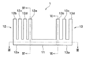
図1、図2に示すように、この冷却装置1は、切削加工、ウエットエッチング加工、メッキ加工等で成形された金属製(例えば、アルミ製)の連結部11、冷却部12、放熱部13を有している。図2中の破線は、連結部11、冷却部12、放熱部13の境界を示す仮想的な線である。
As shown in FIGS. 1 and 2, the
連結部11は、冷却部12と放熱部13の間で冷却部12および放熱部13に連結され、EHD流体を作動流体として冷却部12から放熱部13に熱を輸送するための部材である。
The connecting
冷却部12は、発熱体2〜4に対面すると共に発熱体2〜4を挟み込んで発熱体2〜4と接触している。これによって冷却部12は、発熱体2〜4が発生した熱を熱伝導により受けることができる。
The cooling
放熱部13は、空冷フィン5、6に対面すると共に空冷フィン5、6を挟み込んで空冷フィン5、6と接触している。これによって放熱部13は、連結部11からEHD流体を介して輸送された熱を空冷フィン5、6に熱伝達し、さらに空冷フィンから、熱伝達により冷却装置1の外部に熱を放出する。
The
また、冷却部12は、互いに一体に形成された冷却基部12aおよび複数の冷却壁部12b〜12eを備えている。冷却基部12aは、連結部11と連結されている。
The cooling
複数の冷却壁部12b〜12eは、冷却基部12aの上面から垂直に立ち上がって互いに平行に並ぶ複数の直方体形状の部材であり、隣り合う冷却壁部間に発熱体2〜4のそれぞれを挟み込んで発熱体2〜4に接触することで、発熱体2〜4が発生した熱を熱伝導によって受けるようになっている。冷却壁部12b〜12eと発熱体2〜4との間の熱伝導は、直接接触による熱伝導であってもよいし、他の熱伝導性の高い物質を間に挟んだ間接的な熱伝導であってもよい。
The plurality of cooling
このように、冷却部12が複数枚の冷却壁部12b〜12eを有し、それらの間に発熱体2〜4が挟まれることで、発熱体2〜4と冷却部12との間の接触面積を大きくすることができる。なお冷却基部12aも、僅かながら発熱体2〜4に対面して接触している。
Thus, the cooling
放熱部13は、互いに一体に形成された放熱基部13aおよび放熱壁部13b〜13dを備えている。放熱基部13aは、直方体形状の部材であり、側面の1つが連結部11に一体に連結されている。
The
放熱壁部13b〜13dは、放熱基部13aの上面から垂直に立ち上がって互いに平行に並ぶ複数の直方体形状の部材であり、隣り合う壁部間に空冷フィン5、6をそれぞれを挟み込んで空冷フィン5、6に接触することで、空冷フィン5、6に熱伝導する。放熱壁部13b〜13dと空冷フィン5、6との間の熱伝導は、直接接触による熱伝導であってもよいし、他の熱伝導性の高い物質を間に挟んだ間接的な熱伝導であってもよい。
The heat radiating
このように、放熱部13が複数枚の放熱壁部13b〜13dを有し、それらの間に空冷フィン5、6が挟まれることで、空冷フィン5、6と放熱部13との間の接触面積を大きくすることができる。なお放熱基部13aも、僅かながら空冷フィン5、6に対面して接触している。
Thus, the
図3に、図2のIII−III断面図を示す。この図に示すように、連結部11の内部には、EHD流体を放熱部13の放熱基部13a内から導入して冷却部12の冷却基部12a内に流し出すための上り連結流路111と、EHD流体を冷却部12の冷却基部12a内から導入して放熱部13の放熱基部13a内に流し出すための下り連結流路112とが形成されている。この流路111、112は上述の通り切削加工、ウエットエッチング加工、メッキ加工等によって形成される。
FIG. 3 is a cross-sectional view taken along the line III-III in FIG. As shown in this figure, an ascending
流路111、112のサイズとしては、例えば、図3の上下方向(EHD流体の流れに沿った方向)の長さは冷却部と放熱部の適切な配置を連結するための距離でよく、断面形状が例えば四角形ならば、例として、四角形の高さ(図2の上下方向の長さ)が0.05〜10mm、断面の四角形の幅(図3の左右方向の長さ)が0.05〜10mmが可能である。
As the size of the
また、冷却基部12aの内部には、上り冷却基部流路121および下り冷却基部流路122が、上述の通り切削加工、ウエットエッチング加工、メッキ加工等によって形成されている。上り冷却基部流路121は、上り連結流路111と連通することで、EHD流体を上り連結流路111から導入して上記冷却壁部12b〜12e内に流し出すための流路である。下り冷却基部流路122は、下り連結流路112と連通することで、EHD流体を上記冷却壁部12b〜12e内から導入して下り連結流路112に流し出すための流路である。
In addition, an ascending
流路121、122の断面形状は、四角形である必要はないが、例えば四角形となっている。また、、断面形状が例えば四角形ならば、高さ(図2の上下方向の長さ)は流路111、112と同じく0.05〜10mm、断面の四角形の幅(図3の左右方向の長さ)は流路111、112と同じく0.05〜10mmが可能である。つまり、流路121、122は、流路111、112と同じ太さである。
The cross-sectional shapes of the
また、放熱基部13aの内部には、上り放熱基部流路131および下り放熱基部流路132が、上述の通り切削加工、ウエットエッチング加工、メッキ加工等によって形成されている。上り放熱基部流路131は、上り連結流路111と連通することで、EHD流体を上述の放熱壁部13b〜13d内から導入して上り連結流路111に流し出すための流路である。下り放熱基部流路132は、下り連結流路112と連通することで、EHD流体を下り連結流路112から導入して上述の放熱壁部13b〜13d内に流し出すための流路である。
In addition, the ascending heat dissipating
流路131、132の断面形状は、四角形である必要はないが、例えば四角形となっている。また、断面の形状が例えば四角形ならば、高さ(図2の上下方向の長さ)は流路111、112と同じく0.05〜10mm、断面の四角形の幅(図3の左右方向の長さ)は流路111、112と同じく0.05〜10mm。つまり、流路131、132は、流路111、112と同じ太さである。
The cross-sectional shapes of the
次に、冷却壁部12b〜12eの各々の内部構造について説明する。以下では、冷却壁部12eを例に挙げて説明するが、他の冷却壁部12b〜12dについても、内部構造は冷却壁部12eと同じである。
Next, the internal structure of each of the cooling
図4に、図2のIV−IV断面図(すなわち、冷却壁部12eの断面図)を示し、図5に、図4のV−V断面図を示す。これらの図に示すように、冷却壁部12eの内部には、上り冷却幹流路123、下り冷却幹流路124、および複数の冷却支流路125a〜125gが、上述の通り切削加工、ウエットエッチング加工、メッキ加工等によって形成されている。
4 is a sectional view taken along the line IV-IV in FIG. 2 (that is, a sectional view of the
上り冷却幹流路123は、冷却基部12aの上り冷却基部流路121と連通することで、EHD流体を上り冷却基部流路121から流入させるための流路である。下り冷却幹流路124は、冷却基部12aの下り冷却基部流路122と連通することで、EHD流体を下り冷却基部流路122に流出させるための流路である。
The ascending cooling
また、冷却支流路125a〜125gは、等間隔かつ互いに平行に上り冷却幹流路123から下り冷却幹流路124まで伸びる流路であり、上り冷却幹流路123および下り冷却幹流路124に連通することでEHD流体を上り冷却幹流路123から導入して下り冷却幹流路124に流し出すようになっている。
The cooling
流路123、124の断面形状は、例えば四角形となっていてもよい。また、流路123、124のサイズとしては、断面が四角形ならば、高さ(図2の左右方向の長さ)は流路111、112と同じく0.05〜10mm、断面が四角形ならば、幅(図4の左右方向の長さ)は流路111、112と同じく0.05〜10mmする。つまり、流路123、124は、流路111、112と同じ太さである。
The cross-sectional shape of the
冷却支流路125a〜125gのそれぞれも、断面形状は例えば四角形となっていてもよい。断面が四角形ならば、高さ(図2の左右方向の長さ)は流路123、124と同じく0.05〜10mmとする。
Each of the cooling
また、冷却支流路125a〜125gの断面が四角形ならば、その幅(図4の上下方向の長さ)は流路123、124の幅の1/7より短い((0.05〜10)/7)mmとする。つまり、冷却支流路125a〜125gのそれぞれの幅は、流路123、124の幅を冷却支流路125a〜125gの本数で除算した長さよりも短くなる。
In addition, if the cross-sections of the cooling
このように、複数の冷却支流路125a〜125gの各断面積の総和は、上り冷却幹流路123の断面積よりも下り冷却幹流路124の断面積よりも上り冷却基部流路121の断面積よりも下り冷却基部流路122の断面積よりも上り連結流路111の断面積よりも下り連結流路112の断面積よりも小さくなっている。したがって、冷却支流路125a〜125g内におけるEHD流体の流速は、他の流路111、112、121、122、123、124内よりも速くなっている。このようにすることで、冷却部12内のEHD流体の流速を上げ、EHD流体とそのEHD流体が接する冷却部間の熱伝達率を向上させることにより冷却効率を高めている。
As described above, the sum of the cross-sectional areas of the plurality of cooling
このように、冷却部12の内部には、上り連結流路111および下り連結流路112に連通することでEHD流体を上り連結流路111から導入して下り連結流路112に流し出し、上り連結流路111や下り連結流路112よりも流路断面積が小さくかつEHD流体の流速の速い部分を有する冷却部内流路(すなわち、流路121、122、123、124、125a〜125gから構成される流路)が形成される。
As described above, the EHD fluid is introduced from the
次に、放熱壁部13b〜13dの各々の内部構造について説明する。以下では、放熱壁部13bを例に挙げて説明するが、他の放熱壁部13c、13dについても、内部構造は放熱壁部13bと同じである。
Next, the internal structure of each of the heat radiating
図6に、図2のVI−VI断面図(すなわち、放熱壁部13bの断面図)を示し、図7に、図6のVII−VII断面図を示す。これらの図に示すように、放熱壁部13bの内部には、上り放熱幹流路133、下り放熱幹流路134、および複数の放熱支流路135a〜135gが、上述の通り切削加工、ウエットエッチング加工、メッキ加工等によって形成されている。
6 is a cross-sectional view taken along the line VI-VI in FIG. 2 (that is, a cross-sectional view of the
上り放熱幹流路133は、放熱基部13aの上り放熱基部流路131と連通することで、EHD流体を上り放熱基部流路131に流出させるための流路である。下り放熱幹流路134は、放熱基部13aの下り放熱基部流路132と連通することで、EHD流体を下り放熱基部流路132から流入させるための流路である。
The upstream heat dissipation
また放熱支流路135a〜135gは、等間隔かつ互いに平行に上り放熱幹流路133から下り放熱幹流路134まで伸びる流路であり、上り放熱幹流路133および下り放熱幹流路134に連通することでEHD流体を下り放熱幹流路134から導入して上り放熱幹流路133に流し出すようになっている。
Further, the heat radiating
流路133、134の断面形状は、四角形となっていてもよい。また、流路133、134のサイズとしては、断面が四角形ならば、その高さ(図2の左右方向の長さ)は流路111、112と同じく0.05〜10mm、断面が四角形ならば、その幅(図6の左右方向の長さ)は流路111、112と同じく0.05〜10mmとする。つまり、流路133、134は、流路111、112と同じ太さである。
The cross-sectional shape of the
放熱支流路135a〜135gのそれぞれも、断面形状は四角形となっていてもよい。また、放熱支流路135a〜135gのサイズとしては、断面が四角形ならば、その高さ(図2の左右方向の長さ)は流路133、134と同じく0.05〜10mmとする。
Each of the heat radiating
また、放熱支流路135a〜135gの断面が四角形ならば、その幅(図6の上下方向の長さ)は流路133、134の幅の1/7より短い((0.05〜10)/7)mmとする。つまり、放熱支流路135a〜135gのそれぞれの幅は、流路133、134の幅を放熱支流路135a〜135gの本数で除算した長さよりも短くなる。
Further, if the cross sections of the heat
このように、複数の放熱支流路135a〜135gの各断面積の総和は、上り放熱幹流路133の断面積よりも下り放熱幹流路134の断面積よりも上り放熱基部流路131の断面積よりも下り放熱基部流路132の断面積よりも上り連結流路111の断面積よりも下り連結流路112の断面積よりも小さくなっている。したがって、放熱支流路135a〜135g内におけるEHD流体の流速は、他の流路111、112、131、132、133、134内よりも速くなっている。このようにすることで、放熱部13内のEHD流体の流速を上げ、EHD流体とそのEHD流体が接する放熱部間の熱伝達率を向上させることで放熱効率を高めている。
As described above, the sum of the cross-sectional areas of the plurality of heat radiating
このように、放熱部13の内部には、上り連結流路111および下り連結流路112に連通することでEHD流体を下り連結流路112から導入して上り連結流路111に流し出し、上り連結流路111よりも下り連結流路112よりも流路断面積が小さくすることで、EHD流体の流速の速い部分を有する放熱部内流路(すなわち、流路131、132、133、134、135a〜135gから構成される流路)が形成される。
As described above, the EHD fluid is introduced from the downstream
このように、上り連結流路111、上り冷却基部流路121、上り冷却幹流路123、冷却支流路125a〜125g、下り冷却幹流路124、下り冷却基部流路122、下り連結流路112、下り放熱基部流路132、下り放熱幹流路134、放熱支流路135a〜135g、上り放熱幹流路133、および上り放熱基部流路131から成る流路が形成され、これらの流路にEHD流体が充填され、この順にEHD流体が流れる。
As described above, the
そして、このようEHD流体の流れを実現するため、図3、図4、図6に示すように、このような流路111、121、123、125a〜125g、124、122、112、132、134、135a〜135g、133、131の内部の複数位置のそれぞれには、EHD流体に電圧を印加することでEHD流体を上記のように流動させるポンプ20が配置されている。これらポンプ20も、冷却装置1の構成要素である。図3、図4、図6中では、ポンプ20は流路中の黒点で示されており、それらのポンプ20のうち便宜的に一部にのみ符号20を付している。
In order to realize the flow of the EHD fluid as described above, the
ここで、連結部11、冷却部12、放熱部13のそれぞれにおける、流路内の単位体積当たりのポンプ20の数について説明する。連結部11、冷却部12、放熱部13の設計の時点で、冷却部内流路121、122、123、124、125a〜125gの総体積X、上り連結流路111の体積Y1、下り連結流路112の体積Y2、放熱部内流路131、132、133、134、135a〜135gの総体積Zがわかる。
Here, the number of
そこで、冷却部内流路121、122、123、124、125a〜125g内に配置するポンプ20の個数A、上り連結流路111内に配置するポンプ20の個数B1、下り連結流路112内に配置するポンプ20の個数B2、放熱部内流路131、132、133、134、135a〜135g内に配置するポンプ20の個数Cを、以下の式が満たされるように設定する。
A/X>(B1+B2)/(Y1+Y2)
C/Z>(B1+B2)/(Y1+Y2)
つまり、冷却部内流路121、122、123、124、125a〜125g内における単位体積当たりのポンプ20の個数は、連結部11の上り連結流路111内および下り連結流路112内における単位体積当たりのポンプ20の個数よりも多くする。そして、放熱部内流路131、132、133、134、135a〜135g内における単位体積当たりのポンプ20の個数は、連結部11の上り連結流路111内および下り連結流路112内における単位体積当たりのポンプ20の個数よりも多くする。ただし、冷却部内流路121、122、123、124、125a〜125g内、放熱部内流路131、132、133、134、135a〜135g内における単位体積当たりのポンプ20の数としては、例えば、1個/1立方ミリメートル以上とし、上り連結流路111内および下り連結流路112内における単位体積当たりのポンプ20の個数は、0個/1立方ミリメートル以上する。
Therefore, the number A of the
A / X> (B1 + B2) / (Y1 + Y2)
C / Z> (B1 + B2) / (Y1 + Y2)
That is, the number of
図3の例では、連結部11内においては、上り連結流路111中に1個、下り連結流路112中に1個の計2個、ポンプ20が配置されている。また、図3、図4の例では、冷却部12内においては、上り冷却基部流路121内に4個、下り冷却基部流路122内に4個、上り冷却幹流路123内に6個、下り冷却幹流路124内に6個、冷却支流路125a〜125g内に6×7=42個の計62個、ポンプ20が配置されている。また、図3、図6に示す例では、放熱部13内においては、上り放熱基部流路131内に4個、下り放熱基部流路132内に4個、上り放熱幹流路133内に6個、下り放熱幹流路134内に6個、放熱支流路135a〜135g内に6×7=42個の計62個、ポンプ20が配置されている。
In the example of FIG. 3, two
なお、以上のポンプ数は一例であって、必ずしもこのようなポンプ数である必要はなく、冷却部の流路内及び放熱器内の流路内に設置される単位体積あたりのポンプ数がそれぞれ連結部の流路内に設置される単位体積あたりのポンプ数よりも多ければよい。 The number of pumps described above is an example, and is not necessarily such a number of pumps. The number of pumps per unit volume installed in the flow path of the cooling unit and the flow path of the radiator is respectively What is necessary is just to have more than the number of pumps per unit volume installed in the flow path of a connection part.
以下、各ポンプ20の構造について、図8〜図10を用いて説明する。図8は、図3、図4、または図6における1つのポンプ20の拡大図である。また、図9は図8のIX−IX断面図であり、図10は図8のX−X断面図である。
Hereinafter, the structure of each
これらの図に示す通り、複数のポンプ20のそれぞれは、1つの尖形電極21および1つのスリット電極22を有している。金属製の尖形電極21および金属製のスリット電極22は、互いに離れて流路の内壁に固定される。このとき、流路の内壁とポンプ20の間には、フェノール樹脂等の絶縁体(図示せず)を介在させることで、ポンプ20と連結部11、冷却部12、放熱部13とが導通しないようになっている。流路の内壁、絶縁体、ポンプ20間の固定は、例えば接着剤を用いて実現する。
As shown in these drawings, each of the plurality of
図8、図10に示す通り、尖形電極21はEHD流体の流れの上流側に配置され、スリット電極22は流れの下流側に配置されている。
As shown in FIGS. 8 and 10, the pointed
尖形電極21は、スリット電極22の切り欠きが形成されている部分に向かって先細る形状となっていることで、その先細った先端に電界が集中するようになっている。より具体的には、尖形電極21は、図8〜図10に示すように、線状の先端から4つの面(2つの平行な面と2つの斜交する面)が伸びるくさび形状になっている。また、他の例として、尖形電極21は、1点を先端としてそこから放射状に伸びる直線群から形づくられる錐体形状になっていてもよい。
The pointed
スリット電極22は、一部が切り欠かれたスリット形状になっている。また、他の例として、スリット電極22を、環状の電極としてもよい。スリット電極22が、スリット形状となっていることで、当該ポンプ20が配置されている位置の流路が更に狭められ、その部分におけるEHD流体の流速が更に大きくなる。
The
なお、図示しないが、連結部11、冷却部12および放熱部13(以下、総称してケーシング11〜13という)中の各ポンプ20の近傍には、当該ケーシング11〜13の内部と外部を連通させる孔が2つ形成され、それらの孔には、フェノール樹脂等の絶縁体で周囲を覆われた導通用電極が密着して挿入され、それら導通用電極および導線7a、7bを介して電源7の電力が尖形電極21、スリット電極22に供給される。例として、尖形電極21が負極となり、スリット電極22が正極となる場合を図示する。(使用するEHDによっては電極の正極、負極を逆転しても問題がない)
例えば、尖形電極21が負極となり、スリット電極22が正極となって、EHD流体に電圧が印加されると、EHD効果によってEHD流体が尖形電極21からスリット電極22の方向に加速され、その結果、EHD流体が流路内で流動し、流路に沿って上り連結流路111、上り冷却基部流路121、上り冷却幹流路123、冷却支流路125a〜125g、下り冷却幹流路124、下り冷却基部流路122、下り連結流路112、下り放熱基部流路132、下り放熱幹流路134、放熱支流路135a〜135g、上り放熱幹流路133、上り放熱基部流路131、上り連結流路111という経路で循環する。
Although not shown, in the vicinity of each pump 20 in the connecting
For example, when a voltage is applied to the EHD fluid when the pointed
以上説明した通り、冷却装置1において、冷却部内流路(すなわち、冷却部12内の流路121、122、123、124、125a〜125g)内では、上り連結流路111よりも下り連結流路112よりも細くかつEHD流体の流速の速い部分(冷却支流路125a〜125g)を有することで、冷却部12内のEHD流体の流速を上げ、EHD流体とそのEHD流体が接する冷却部間の熱伝達率を向上させ、冷却効率を高めている。
As described above, in the
そのような状況において、複数のポンプ20のうち、冷却部内流路121、122、123、124、125a〜125g内における単位体積当たりのポンプ20の個数(または、EHD流体の流れに沿った単位長さ当たりのポンプ20の個数)を、連結部11の上り連結流路111内および下り連結流路112内における単位体積当たりのポンプ20の個数(または、EHD流体の流れに沿った単位長さ当たりのポンプ20の個数)よりも多くすることで、流速を増加させて、EHD流体とそのEHD流体が接する部位間の熱伝達率を向上させることができる。その結果、発熱体2〜4の冷却効率を従来よりも高めることができる。
In such a situation, among the plurality of
また同様に、放熱部内流路(すなわち、放熱部13内の流路131、132、133、134、135a〜135g)内では、上り連結流路111よりも下り連結流路112よりも細くかつEHD流体の流速の速い部分(放熱支流路135a〜135g)を有することで、冷却部12内のEHD流体の流速を上げ、EHD流体とそのEHD流体が接する放熱部間の熱伝達率を向上させ、放熱効率を高めている。
Similarly, in the flow path in the heat radiating section (that is, in the
そのような状況において、複数のポンプ20のうち、放熱部内流路131、132、133、134、135a〜135g内における単位体積当たりのポンプ20(または、EHD流体の流れに沿った単位長さ当たりのポンプ20の個数)の個数を、連結部11の上り連結流路111内および下り連結流路112内における単位体積当たりのポンプ20(または、EHD流体の流れに沿った単位長さ当たりのポンプ20の個数)の個数よりも多くすることで、流速を増加させて、EHD流体とそのEHD流体が接する部位間の熱伝達率を向上させる放熱部13における放熱効率を高め、ひいては、発熱体2〜4の冷却効率を従来よりも高めることができる。
In such a situation, among the plurality of
また複数のポンプ20のそれぞれにおいて、ポンプ20を構成するスリット電極22が、当該ポンプ20の位置の流路を更に狭めるようになっていることで、当該流路の流速を上げるとともに、その流速の上がっている位置でポンプ20がEHD流体に電圧印加して駆動しているので、より流速を増加させて、EHD流体とそのEHD流体が接する部位間の熱伝達率を向上させる。ひいては、より高い発熱体2〜4の冷却効率を実現することができる。
(第2実施形態)
次に、本発明の第2実施形態について、第1実施形態と異なる部分を中心に説明する。本実施形態の冷却装置1が第1実施形態と異なるのは、冷却壁部12b〜12e内の管路の構成のみである。
Further, in each of the plurality of
(Second Embodiment)
Next, a second embodiment of the present invention will be described with a focus on differences from the first embodiment. The
図11に、本実施形態の冷却壁部12e内の管路の構成を、図4と同様の形式(すなわち、図2のIV−IV断面図の形式)で示す。他の冷却壁部12b〜12d内の管路の構成も、この冷却壁部12eと同じである。
FIG. 11 shows the configuration of the pipeline in the
この図11に示すように、本実施形態の冷却壁部12eの内部には、一本の蛇行した冷却壁部内管路126が、切削加工、ウエットエッチング加工、メッキ加工等によって形成されている。
As shown in FIG. 11, inside the cooling
この冷却壁部内管路126は、一端で上り冷却基部流路121に連通し、冷却壁部12e内を蛇行するように延び、他端で下り冷却基部流路122に連通している。このようになっていることで、冷却壁部内管路126は、上り冷却基部流路121から下り冷却基部流路122にEHD流体を流すことができる。
The cooling wall
冷却壁部内管路126の断面形状は、例えば四角形となっていてもよい。また、冷却壁部内管路126のサイズとしては、例えば、断面が四角形ならば、その高さ(図2の左右方向の長さ)は流路121、122と同じく0.05〜10mmとする。
The cross-sectional shape of the cooling wall portion
また、冷却支流路125a〜125gの断面が四角形ならば、その幅(図11面内かつEHD流体の流れに垂直な方向)は、流路121、122の幅より短い幅(例えば1mm)とする。
Further, if the cross section of the cooling
このように、複数の冷却壁部内管路126の断面積(太さ)は、上り冷却基部流路121の断面積よりも下り冷却基部流路122の断面積よりも上り連結流路111の断面積よりも下り連結流路112の断面積よりも小さくなっている。したがって、冷却壁部内管路126内におけるEHD流体の流速は、他の流路111、112、121、122内よりも速くなっている。このようにすることで、冷却部12内のEHD流体の流速を上げ、EHD流体とそのEHD流体が接する冷却部間の熱伝達率を向上させ、冷却効率を高めている。
As described above, the cross-sectional area (thickness) of the plurality of cooling wall
このように、冷却部12の内部には、上り連結流路111および下り連結流路112に連通することでEHD流体を上り連結流路111から導入して下り連結流路112に流し出し、上り連結流路111よりも下り連結流路112よりも細くかつEHD流体の流速の速い部分を有する冷却部内流路(すなわち、流路121、122、126から構成される流路)が形成される。
As described above, the EHD fluid is introduced from the
そして、図11に示すように、このような冷却壁部内管路126の内部の複数位置(冷却壁部内管路126中の黒点の位置)のそれぞれにも、第1実施形態と同じポンプ20が第1実施形態と同様の取り付け方法で配置されており、これらのポンプ20に電圧が印加されることで、冷却壁部内管路126において上り連結流路111側から下り連結流路112側にEHD流体が流動する。
As shown in FIG. 11, the
ここでも、冷却部12の設計の時点で、冷却部内流路121、122、126の総体積X’がわかる。そこで、冷却部内流路121、122、126内に配置するポンプ20の個数A’、上り連結流路111内に配置するポンプ20の個数B1、下り連結流路112内に配置するポンプ20の個数B2を、以下の式が満たされるように設定する。
A’/X>(B1+B2)/(Y1+Y2)
つまり、冷却部内流路121、122、126内における単位体積当たりのポンプ20の個数は、連結部11の上り連結流路111内および下り連結流路112内における単位体積当たりのポンプ20の個数よりも多くする。ただし、冷却部内流路121、122、126内における単位体積当たりのポンプ20の数としては、例えば、1個/1立方ミリメートル以上とし、上り連結流路111内および下り連結流路112内における単位体積当たりのポンプ20の個数は、0個/1立方ミリメートル以上する。
Here too, at the time of designing the cooling
A ′ / X> (B1 + B2) / (Y1 + Y2)
That is, the number of
図3、図11の例では、冷却部12内においては、上り冷却基部流路121内に4個、下り冷却基部流路122内に4個、冷却壁部内管路126に24個の計32個、ポンプ20が配置されていることになる。
In the example of FIGS. 3 and 11, in the
このように、第1実施形態と同様に、冷却装置1において、冷却部内流路(すなわち、冷却部12内の流路121、122、126)内では、上り連結流路111よりも下り連結流路112よりも細くかつEHD流体の流速の速い部分(冷却壁部内管路126)を有することで、冷却部12内のEHD流体の流速を上げ、EHD流体とそのEHD流体が接する冷却部間の熱伝達率を向上させ、冷却効率を高めている。
Thus, similarly to the first embodiment, in the
そのような状況において、複数のポンプ20のうち、冷却部内流路121、122、126内における単位体積当たりのポンプ20の個数(または、EHD流体の流れに沿った単位長さ当たりのポンプ20の個数)を、連結部11の上り連結流路111内および下り連結流路112内における単位体積当たりのポンプ20の個数(または、EHD流体の流れに沿った単位長さ当たりのポンプ20の個数)よりも多くすることで、流速を増加させて、EHD流体とそのEHD流体が接する部位間の熱伝達率を向上させることができる。その結果、発熱体2〜4の冷却効率を従来よりも高めることができる。
In such a situation, among the plurality of
また同様に、複数のポンプ20のそれぞれにおいて、ポンプ20を構成するスリット電極22が、当該ポンプ20の位置の流路を更に狭めるようになっていることで、当該流路の流速を上げるとともに、その流速の上がっている位置でポンプ20がEHD流体に電圧印加して駆動しているので、より流速を増加させて、EHD流体とそのEHD流体が接する部位間の熱伝達率を向上させる。ひいては、より高い発熱体2〜4の冷却効率を実現することができる。
(第3実施形態)
次に、本発明の第2実施形態について、第1実施形態と異なる部分を中心に説明する。本実施形態の冷却装置1が第1実施形態と異なるのは、冷却壁部12b〜12e内の管路の構成のみである。
Similarly, in each of the plurality of
(Third embodiment)
Next, a second embodiment of the present invention will be described with a focus on differences from the first embodiment. The
図12に、本実施形態の冷却壁部12e内の管路の構成を、図4と同様の形式(すなわち、図2のIV−IV断面図の形式)で示し、図13に、図12のXIII−XIII断面図を示し、図14に、図12の二点鎖線40で囲んだ部分の拡大図を示す。他の冷却壁部12b〜12d内の管路の構成も、この冷却壁部12eと同じである。
FIG. 12 shows the configuration of the pipeline in the
これらの図に示すように、本実施形態の複数の冷却壁部12eの内部には、タンク流入管路127、タンク流出管路128、およびタンク129が、切削加工、ウエットエッチング加工、メッキ加工等によって形成されている。
As shown in these drawings, a
タンク流入管路127は、冷却基部12aの上り冷却基部流路121と連通することで、EHD流体を上り冷却基部流路121から流入させるための流路である。また、タンク流出管路128は、冷却基部12aの下り冷却基部流路122と連通することで、EHD流体を下り冷却基部流路122に流出させるための流路である。
The
流路127、128の断面形状は、四角形となっているてもうよい。また、流路127、128のサイズとしては、例えば、断面が四角形ならば、その高さ(図2の左右方向の長さ)は流路121、122と同じく0.05〜10mm、断面が四角形ならば、その幅(図6の左右方向の長さ)は流路121、122と同じく0.05〜10mmとする。つまり、流路127、128は、流路121、122と同じ太さである。
The cross-sectional shape of the
また、タンク129は、一部が円盤形状に形成され、タンク流入流路127およびタンク流出流路128に連通し、それにより、EHD流体をタンク流入流路127から導入して下りタンク流出流路128に流し出すようになっている。
The
このタンク129は、タンク流入管路127およびタンク流出管路128に比べても体積が遙かに大きく、冷却壁部12eの大部分を占めるほどであり、更に、一部は冷却基部12a内にまで伸びている。このようになっていることで、タンク129内には、大量のEHD流体を一時的に貯留することができる。例えば、タンク129のサイズとしては、厚み(図2の左右方向の長さ)は流路127、128と同じく0.05〜10mm、容積が冷却壁部12eの外形の体積の30%以上とする。
The
このように、冷却部12の内部には、上り連結流路111および下り連結流路112に連通することでEHD流体を上り連結流路111から導入して下り連結流路112に流し出す冷却部内流路121、122、127、128と、冷却部内流路121、122、127、128と連通し、EHD流体を一時的に貯留する円盤状のタンク129とが形成されている。
As described above, inside the cooling
また、タンク129内の複数箇所(冷却壁部内管路126中の黒点の位置)には、第1実施形態と同じポンプ20が、第1実施形態同様の取り付け方法で配置されている。これらのポンプ20に電圧が印加されることで、冷却壁部内管路126においてEHD流体が流動する。
In addition, the
具体的には、図12、図14に示すように、ポンプ20がタンク129の周縁部の4箇所に等間隔に配置され、図12中で時計回り方向にEHD流体が駆動されるような配置で、ポンプ20の尖形電極21およびスリット電極22が配置されている。
Specifically, as shown in FIGS. 12 and 14, the
このようにポンプ20が配置されることで、タンク129内のポンプ20によって電圧が印加されたEHD流体は、タンク129内を矢印のように時計回りに循環すると共に、一部がタンク流出管路128から下り冷却基部流路122に流出し、その分、上り冷却基部流路121、タンク流入管路127を介してEHD流体が流入する。
By arranging the
この循環により、冷却部12、連結部11、放熱部13を循環するEHD流体の主流(タンク流出管路128、下り冷却基部流路122、下り連結流路112、下り放熱基部流路132、下り放熱幹流路134、放熱支流路135a〜135g、上り放熱幹流路133、上り放熱基部流路131、上り連結流路111、上り冷却基部流路121、タンク流入管路127の流れ)とは別に、タンク129内のEHD流体の流速を高くすることができる。
By this circulation, the main flow of the EHD fluid circulating through the cooling
また、さらにタンク129内には、EHD流体と冷却部12との接触面積を多くするための複数枚の板状の放熱フィン30、31が、EHD流体の流れに沿って冷却部12と一体に形成されている。この放熱フィン30、31により、発熱体2〜4の冷却効果が更に高まる。
Further, in the
以上のように、冷却部12内において、EHD流体を一時的に貯留するタンク129を形成し、その冷却部12内でEHD流体が循環するようポンプ20を配置することで、冷却部12、連結部11、放熱部13を循環するEHD流体の流れ(主流)とは別の流れを冷却部12内に発生させることができ、それにより、冷却部12内のEHD流体の流速を主流とは独立に上げることができ、ひいては、従来よりも効率の高い発熱体2〜4の冷却を実現することができる。
As described above, the
(他の実施形態)
以上、本発明の実施形態について説明したが、本発明の範囲は、上記実施形態のみに限定されるものではなく、本発明の各発明特定事項の機能を実現し得る種々の形態を包含するものである。
(Other embodiments)
As mentioned above, although embodiment of this invention was described, the scope of the present invention is not limited only to the said embodiment, The various form which can implement | achieve the function of each invention specific matter of this invention is included. It is.
例えば、上記各実施形態において、放熱壁部13b〜13d内の流路の構造は、図4、図5に示した通りだが、放熱壁部13b〜13dの構造を、図11と同様なものにしてもよい。具体的には、図11において、冷却壁部12eを放熱壁部13b〜13dのそれぞれに置き換え、冷却基部12aを放熱基部13aに置き換え、上り冷却基部流路121を下り放熱基部流路132に置き換え、下り冷却基部流路122を上り放熱基部流路131に置き換えればよい。
For example, in each of the embodiments described above, the structure of the flow paths in the heat radiating
また、放熱壁部13b〜13dの構造を、図12〜図14と同様なものにしてもよい。具体的には、図12において、冷却壁部12eを放熱壁部13b〜13dのそれぞれに置き換え、冷却基部12aを放熱基部13aに置き換え、上り冷却基部流路121を下り放熱基部流路132に置き換え、下り冷却基部流路122を上り放熱基部流路131に置き換えればよい。
Moreover, you may make the structure of the thermal
また、各ポンプ20の尖形電極21、スリット電極22は、上記実施形態のような形状でなく、流路の内壁に(絶縁体を介して)貼り付けられた平面導体パターンであってもよい。
Further, the pointed
また、冷却装置1による冷却対象であるスイッチング素子を備えたインバータは、ハイブリッド車両に限らず、列車(新幹線、電車等)、エレベータ等のモータの駆動用として用いられてもよい。
Moreover, the inverter provided with the switching element to be cooled by the
また、冷却装置1の冷却対象は、スイッチング素子に限らず、周囲の環境温度よりも高温で発熱する発熱体ならどのようなものでもよく、例えば、CPUでもよい。
The cooling target of the
1 冷却装置
2〜4 発熱体
11 連結部
12 冷却部
12a 冷却基部
12b〜12e 冷却壁部
13 放熱部
13a 放熱基部
13b〜13d 放熱壁部
20 ポンプ
21 尖形電極
22 スリット電極
30、31 放熱フィン
111、112 連結流路
121、122 冷却基部流路
123、124 冷却幹流路
125a〜125g 冷却支流路
126 冷却壁部内管路
127 タンク流入管路
128 タンク流出管路
129 タンク
131、132 放熱基部流路
133、134 放熱幹流路
135a〜135g 放熱支流路
DESCRIPTION OF
Claims (5)
前記発熱体(2〜4)に対面し、前記発熱体(2〜4)が発生した熱を熱伝導により受ける冷却部(12)と、
当該冷却装置の外部に熱を放出する放熱部(13)と、
前記冷却部(12)および前記放熱部(13)に連結され、前記冷却部(12)から前記放熱部(13)に熱を輸送するための連結部(11)と、を備え、
前記連結部(11)の内部には、EHD流体を前記放熱部(13)内から前記冷却部(12)内に流すための上り連結流路(111)と、EHD流体を前記冷却部(12)内から前記放熱部(13)内に流すための下り連結流路(112)と、が形成され、
前記冷却部(12)の内部には、前記上り連結流路(111)および前記下り連結流路(112)に連通することでEHD流体を前記上り連結流路(111)から前記下り連結流路(112)に流し、前記上り連結流路(111)よりも前記下り連結流路(112)よりも細くかつEHD流体の流速の速い部分を有する冷却部内流路(121、122、123、124、125a〜125g、126)が形成され、
前記放熱部(13)の内部には、前記上り連結流路(111)および前記下り連結流路(112)に連通することでEHD流体を前記下り連結流路(112)から前記上り連結流路(111)に流すための放熱部内流路(131、132、133、134、135a〜135g)が形成され、
前記上り連結流路(111)、前記冷却部内流路(121、122、123、124、125a〜125g、126)、前記下り連結流路(112)および前記放熱部内流路(131、132、133、134、135a〜135g)から成る流路の内部の複数位置のそれぞれには、EHD流体に電圧を印加することでEHD流体を流動させるポンプ(20)が配置され、
それら複数のポンプ(20)のうち、前記冷却部内流路(121、122、123、124、125a〜125g、126)内における単位体積当たりのポンプ(20)の個数は、前記連結部(11)の前記上り連結流路(111)内および前記下り連結流路(112)内における単位体積当たりのポンプ(20)の個数よりも多いことを特徴とする冷却装置。 A cooling device for cooling a heating element (2-4) using an EHD fluid flowing by an electrohydrodynamic (EHD for short) effect,
A cooling unit (12) facing the heating element (2-4) and receiving heat generated by the heating element (2-4) by heat conduction;
A heat dissipating part (13) for releasing heat to the outside of the cooling device;
A connection part (11) connected to the cooling part (12) and the heat dissipation part (13), for transporting heat from the cooling part (12) to the heat dissipation part (13),
Inside the connecting part (11), an upstream connecting flow path (111) for allowing EHD fluid to flow from inside the heat dissipating part (13) into the cooling part (12), and EHD fluid flowing into the cooling part (12) ) And a downstream connecting flow path (112) for flowing into the heat radiating portion (13) from inside,
In the cooling part (12), the EHD fluid is communicated from the upstream connection channel (111) to the downstream connection channel by communicating with the upstream connection channel (111) and the downstream connection channel (112). (112), and the flow path in the cooling section (121, 122, 123, 124, which has a portion that is narrower than the downstream connection flow path (112) and faster in flow rate of the EHD fluid than the upstream connection flow path (111). 125a-125g, 126) are formed,
Inside the heat radiating part (13), the EHD fluid is communicated from the down connecting channel (112) to the up connecting channel by communicating with the up connecting channel (111) and the down connecting channel (112). (111) is formed in the heat dissipating section flow channel (131, 132, 133, 134, 135a-135g),
The upstream connection channel (111), the cooling unit internal channel (121, 122, 123, 124, 125a to 125g, 126), the downward connection channel (112), and the heat dissipation unit internal channel (131, 132, 133). , 134, 135a to 135g), a pump (20) for causing the EHD fluid to flow by applying a voltage to the EHD fluid is disposed at each of a plurality of positions inside the flow path.
Among the plurality of pumps (20), the number of pumps (20) per unit volume in the flow passages in the cooling section (121, 122, 123, 124, 125a to 125g, 126) is the connection section (11). The number of pumps (20) per unit volume in the ascending connection channel (111) and the descending connection channel (112) is larger than the number of pumps (20).
前記発熱体(2〜4)に対面し、前記発熱体(2〜4)が発生した熱を熱伝導により受ける冷却部(12)と、
当該冷却装置の外部に熱を放出する放熱部(13)と、
前記冷却部(12)および前記放熱部(13)に連結され、前記冷却部(12)から前記放熱部(13)に熱を輸送するための連結部(11)と、を備え、
前記連結部(11)の内部には、EHD流体を前記放熱部(13)内から前記冷却部(12)内に流すための上り連結流路(111)と、EHD流体を前記冷却部(12)内から前記放熱部(13)内に流すための下り連結流路(112)と、が形成され、
前記冷却部(12)の内部には、前記上り連結流路(111)および前記下り連結流路(112)に連通することでEHD流体を前記上り連結流路(111)から前記下り連結流路(112)に流すための冷却部内流路(121、122、123、124、125a〜125g、126)が形成され、
前記放熱部(13)の内部には、前記上り連結流路(111)および前記下り連結流路(112)に連通することでEHD流体を前記下り連結流路(112)から前記上り連結流路(111)に流し、前記上り連結流路(111)よりも前記下り連結流路(112)よりも細くかつEHD流体の流速の速い部分を有する放熱部内流路(131、132、133、134、135a〜135g)が形成され、
前記上り連結流路(111)、前記冷却部内流路(121、122、123、124、125a〜125g、126)、前記下り連結流路(112)および前記放熱部内流路(131、132、133、134、135a〜135g)から成る流路の内部の複数位置のそれぞれには、EHD流体に電圧を印加することでEHD流体を流動させるポンプ(20)が配置され、
それら複数のポンプ(20)のうち、前記放熱部内流路(131、132、133、134、135a〜135g)内における単位体積当たりのポンプ(20)の個数は、前記連結部(11)の前記上り連結流路(111)内および前記下り連結流路(112)内における単位体積当たりのポンプ(20)の個数よりも多いことを特徴とする冷却装置。 A cooling device for cooling a heating element (2-4) using an EHD fluid flowing by an electrohydrodynamic (EHD for short) effect,
A cooling unit (12) facing the heating element (2-4) and receiving heat generated by the heating element (2-4) by heat conduction;
A heat dissipating part (13) for releasing heat to the outside of the cooling device;
A connection part (11) connected to the cooling part (12) and the heat dissipation part (13), for transporting heat from the cooling part (12) to the heat dissipation part (13),
Inside the connecting part (11), an upstream connecting flow path (111) for allowing EHD fluid to flow from inside the heat dissipating part (13) into the cooling part (12), and EHD fluid flowing into the cooling part (12) ) And a downstream connecting flow path (112) for flowing into the heat radiating portion (13) from inside,
In the cooling part (12), the EHD fluid is communicated from the upstream connection channel (111) to the downstream connection channel by communicating with the upstream connection channel (111) and the downstream connection channel (112). (112), the flow path in the cooling part (121, 122, 123, 124, 125a to 125g, 126) is formed,
Inside the heat radiating part (13), the EHD fluid is communicated from the down connecting channel (112) to the up connecting channel by communicating with the up connecting channel (111) and the down connecting channel (112). (111), and the flow path in the heat radiating section (131, 132, 133, 134, which has a portion that is narrower than the downstream connection flow path (112) and faster in flow rate of the EHD fluid than the upstream connection flow path (111). 135a-135g) are formed,
The upstream connection channel (111), the cooling unit internal channel (121, 122, 123, 124, 125a to 125g, 126), the downward connection channel (112), and the heat dissipation unit internal channel (131, 132, 133). , 134, 135a to 135g), a pump (20) for causing the EHD fluid to flow by applying a voltage to the EHD fluid is disposed at each of a plurality of positions inside the flow path.
Among the plurality of pumps (20), the number of pumps (20) per unit volume in the flow passages (131, 132, 133, 134, 135a to 135g) in the heat radiating portion is the number of the pumps (20) in the connecting portion (11). The cooling device, wherein the number of pumps (20) per unit volume in the upstream connecting channel (111) and the downstream connecting channel (112) is larger.
前記発熱体(2〜4)に対面し、前記発熱体(2〜4)が発生した熱を熱伝導により受ける冷却部(12)と、
当該冷却装置の外部に熱を放出する放熱部(13)と、
前記冷却部(12)および前記放熱部(13)に連結され、前記冷却部(12)から前記放熱部(13)に熱を輸送するための連結部(11)と、を備え、
前記連結部(11)の内部には、EHD流体を前記放熱部(13)内から前記冷却部(12)内に流すための上り連結流路(111)と、EHD流体を前記冷却部(12)内から前記放熱部(13)内に流すための下り連結流路(112)と、が形成され、
前記冷却部(12)の内部には、前記上り連結流路(111)および前記下り連結流路(112)に連通することでEHD流体を前記上り連結流路(111)から前記下り連結流路(112)に流すための冷却部内流路(121、122、127、128)と、前記冷却部内流路(121、122、127、128)と連通し、EHD流体を一時的に貯留するタンク(129)とが形成され、
前記放熱部(13)の内部には、前記上り連結流路(111)および前記下り連結流路(112)に連通することでEHD流体を前記下り連結流路(112)から前記上り連結流路(111)に流すための放熱部内流路(131、132、133、134、135a〜135g)が形成され、
前記上り連結流路(111)、前記冷却部内流路(121、122、127、128)、前記下り連結流路(112)および前記放熱部内流路(131、132、133、134、135a〜135g)から成る流路の内部の複数位置のそれぞれには、EHD流体に電圧を印加することでEHD流体を流動させるポンプ(20)が配置され、
また、前記タンク(129)内にも、複数のポンプ(20)が配置され、前記タンク(129)内の前記複数のポンプ(20)は、前記タンク(129)内でEHD流体を循環させるように配置されていることを特徴とする冷却装置。 A cooling device for cooling a heating element (2-4) using an EHD fluid flowing by an electrohydrodynamic (EHD for short) effect,
A cooling unit (12) facing the heating element (2-4) and receiving heat generated by the heating element (2-4) by heat conduction;
A heat dissipating part (13) for releasing heat to the outside of the cooling device;
A connection part (11) connected to the cooling part (12) and the heat dissipation part (13), for transporting heat from the cooling part (12) to the heat dissipation part (13),
Inside the connecting part (11), an upstream connecting flow path (111) for allowing EHD fluid to flow from inside the heat dissipating part (13) into the cooling part (12), and EHD fluid flowing into the cooling part (12) ) And a downstream connecting flow path (112) for flowing into the heat radiating portion (13) from inside,
In the cooling part (12), the EHD fluid is communicated from the upstream connection channel (111) to the downstream connection channel by communicating with the upstream connection channel (111) and the downstream connection channel (112). (112) The flow path (121, 122, 127, 128) in the cooling section for flowing to the tank and the flow path (121, 122, 127, 128) in the cooling section, and a tank for temporarily storing the EHD fluid ( 129), and
Inside the heat radiating part (13), the EHD fluid is communicated from the down connecting channel (112) to the up connecting channel by communicating with the up connecting channel (111) and the down connecting channel (112). (111) is formed in the heat dissipating section flow channel (131, 132, 133, 134, 135a-135g),
The upstream connection flow path (111), the cooling part internal flow path (121, 122, 127, 128), the downward connection flow path (112), and the heat dissipation part internal flow path (131, 132, 133, 134, 135a to 135g). ), A pump (20) for causing the EHD fluid to flow by applying a voltage to the EHD fluid is disposed at each of a plurality of positions inside the flow path.
A plurality of pumps (20) are also disposed in the tank (129), and the plurality of pumps (20) in the tank (129) circulate EHD fluid in the tank (129). The cooling device characterized by being arranged in.
前記発熱体(2〜4)に対面し、前記発熱体(2〜4)が発生した熱を熱伝導により受ける冷却部(12)と、
当該冷却装置の外部に熱を放出する放熱部(13)と、
前記冷却部(12)および前記放熱部(13)に連結され、前記冷却部(12)から前記放熱部(13)に熱を輸送するための連結部(11)と、を備え、
前記連結部(11)の内部には、EHD流体を前記放熱部(13)内から前記冷却部(12)内に流すための上り連結流路(111)と、EHD流体を前記冷却部(12)内から前記放熱部(13)内に流すための下り連結流路(112)と、が形成され、
前記冷却部(12)の内部には、前記上り連結流路(111)および前記下り連結流路(112)に連通することでEHD流体を前記上り連結流路(111)から前記下り連結流路(112)に流すための冷却部内流路(121、122、123、124、125a〜125g、126)とが形成され、
前記放熱部(13)の内部には、前記上り連結流路(111)および前記下り連結流路(112)に連通することでEHD流体を前記下り連結流路(112)から前記上り連結流路(111)に流すための放熱部内流路(131、132、127、128)と、前記放熱部内流路(131、132、127、128)と連通し、EHD流体を一時的に貯留するタンク(129)とが形成され、
前記上り連結流路(111)、前記冷却部内流路(121、122、123、124、125a〜125g、126)、前記下り連結流路(112)および前記放熱部内流路(131、132、127、128)から成る流路の内部の複数位置のそれぞれには、EHD流体に電圧を印加することでEHD流体を流動させるポンプ(20)が配置され、
また、前記タンク(129)内にも、複数のポンプ(20)が配置され、前記タンク(129)内の前記複数のポンプ(20)は、前記タンク(129)内でEHD流体を循環させるように配置されていることを特徴とする冷却装置。 A cooling device for cooling a heating element (2-4) using an EHD fluid flowing by an electrohydrodynamic (EHD for short) effect,
A cooling unit (12) facing the heating element (2-4) and receiving heat generated by the heating element (2-4) by heat conduction;
A heat dissipating part (13) for releasing heat to the outside of the cooling device;
A connection part (11) connected to the cooling part (12) and the heat dissipation part (13), for transporting heat from the cooling part (12) to the heat dissipation part (13),
Inside the connecting part (11), an upstream connecting flow path (111) for allowing EHD fluid to flow from inside the heat dissipating part (13) into the cooling part (12), and EHD fluid flowing into the cooling part (12) ) And a downstream connecting flow path (112) for flowing into the heat radiating portion (13) from inside,
In the cooling part (12), the EHD fluid is communicated from the upstream connection channel (111) to the downstream connection channel by communicating with the upstream connection channel (111) and the downstream connection channel (112). (112) are formed in the cooling section flow passages (121, 122, 123, 124, 125a to 125g, 126),
Inside the heat radiating part (13), the EHD fluid is communicated from the down connecting channel (112) to the up connecting channel by communicating with the up connecting channel (111) and the down connecting channel (112). (111) A flow path (131, 132, 127, 128) in the heat radiating section and a tank (T, 131, 132, 127, 128) communicating with the heat radiating section internal flow path (131, 132, 127, 128) for temporarily storing EHD fluid ( 129), and
The ascending connection channel (111), the cooling unit internal channel (121, 122, 123, 124, 125a to 125g, 126), the down connection channel (112), and the heat dissipation unit internal channel (131, 132, 127). 128), a pump (20) for causing the EHD fluid to flow by applying a voltage to the EHD fluid is disposed at each of a plurality of positions inside the flow path consisting of 128).
A plurality of pumps (20) are also disposed in the tank (129), and the plurality of pumps (20) in the tank (129) circulate EHD fluid in the tank (129). The cooling device characterized by being arranged in.
Priority Applications (1)
| Application Number | Priority Date | Filing Date | Title |
|---|---|---|---|
| JP2010202185A JP5423625B2 (en) | 2010-09-09 | 2010-09-09 | Cooling device using EHD fluid |
Applications Claiming Priority (1)
| Application Number | Priority Date | Filing Date | Title |
|---|---|---|---|
| JP2010202185A JP5423625B2 (en) | 2010-09-09 | 2010-09-09 | Cooling device using EHD fluid |
Publications (2)
| Publication Number | Publication Date |
|---|---|
| JP2012057872A JP2012057872A (en) | 2012-03-22 |
| JP5423625B2 true JP5423625B2 (en) | 2014-02-19 |
Family
ID=46055189
Family Applications (1)
| Application Number | Title | Priority Date | Filing Date |
|---|---|---|---|
| JP2010202185A Expired - Fee Related JP5423625B2 (en) | 2010-09-09 | 2010-09-09 | Cooling device using EHD fluid |
Country Status (1)
| Country | Link |
|---|---|
| JP (1) | JP5423625B2 (en) |
Families Citing this family (9)
| Publication number | Priority date | Publication date | Assignee | Title |
|---|---|---|---|---|
| CN102832779A (en) * | 2012-08-24 | 2012-12-19 | 华南理工大学 | Microminiature electro-hydraulic power pump |
| US9038407B2 (en) * | 2012-10-03 | 2015-05-26 | Hamilton Sundstrand Corporation | Electro-hydrodynamic cooling with enhanced heat transfer surfaces |
| JP6048292B2 (en) * | 2013-04-18 | 2016-12-21 | 株式会社デンソー | EHD pump |
| JP2014212625A (en) * | 2013-04-18 | 2014-11-13 | 株式会社デンソー | EHD pump |
| SE537790C2 (en) * | 2013-12-04 | 2015-10-20 | Apr Technologies Ab | Electrohydrodynamic micropump device and method of manufacture of the device |
| JP6225838B2 (en) * | 2014-06-06 | 2017-11-08 | 株式会社デンソー | Mixture transport device and mixture |
| JP6281470B2 (en) * | 2014-11-06 | 2018-02-21 | 株式会社デンソー | Fluid device |
| SE539310C2 (en) | 2015-06-03 | 2017-06-27 | Rapkap Ab | Microfluidic fan |
| EP3638962A1 (en) * | 2017-06-16 | 2020-04-22 | Carrier Corporation | Ferroic response through application of conjugate field |
Family Cites Families (8)
| Publication number | Priority date | Publication date | Assignee | Title |
|---|---|---|---|---|
| JP3245386B2 (en) * | 1997-10-23 | 2002-01-15 | 有限会社新技術マネイジメント | Micropump, method of using the same, and microactuator utilizing the micropump |
| JP2000222072A (en) * | 1999-02-01 | 2000-08-11 | Shingijutsu Management:Kk | Cooling device |
| JP2003284316A (en) * | 2002-03-25 | 2003-10-03 | Ryoichi Hanaoka | Electrohydrodynamic pump |
| JP4759671B2 (en) * | 2004-11-29 | 2011-08-31 | 学校法人金沢工業大学 | Electrohydrodynamic pump |
| JP2007043041A (en) * | 2005-06-28 | 2007-02-15 | Kyocera Corp | Electric element equipment and electric element module |
| JP5085978B2 (en) * | 2007-05-22 | 2012-11-28 | 和幸 三井 | Electric response fluid pump |
| JP5024265B2 (en) * | 2008-11-21 | 2012-09-12 | 株式会社デンソー | Heat spreader |
| JP5141537B2 (en) * | 2008-12-19 | 2013-02-13 | 株式会社デンソー | Heat sink |
-
2010
- 2010-09-09 JP JP2010202185A patent/JP5423625B2/en not_active Expired - Fee Related
Also Published As
| Publication number | Publication date |
|---|---|
| JP2012057872A (en) | 2012-03-22 |
Similar Documents
| Publication | Publication Date | Title |
|---|---|---|
| JP5423625B2 (en) | Cooling device using EHD fluid | |
| JP5700034B2 (en) | Semiconductor module and cooler | |
| JP5900506B2 (en) | Semiconductor module cooler and semiconductor module | |
| JP5692368B2 (en) | Semiconductor module cooler and semiconductor module | |
| JP6093186B2 (en) | Semiconductor module cooler | |
| BR102012015581A2 (en) | COOLING DEVICE, ENERGY MODULE AND METHOD | |
| JP6482954B2 (en) | Liquid cooling system | |
| JP2013098530A (en) | Heat sink | |
| JP2006310363A (en) | Power semiconductor device | |
| JP6534873B2 (en) | Liquid cooling system | |
| JP2016039202A (en) | Inverter device | |
| JP5667739B2 (en) | Heat sink assembly, semiconductor module, and semiconductor device with cooling device | |
| JP2014212625A (en) | EHD pump | |
| JP6048292B2 (en) | EHD pump | |
| JP2008277442A (en) | Heat dissipation board | |
| KR20140057046A (en) | Cooling system of power semiconductor device | |
| JP2019021825A (en) | Radiator and liquid-cooling type cooling device employing the same | |
| JP6469521B2 (en) | Liquid cooling system | |
| CN211125625U (en) | Liquid cooling heat dissipation assembly, liquid cooling heat dissipation device and power electronic equipment | |
| JP6391533B2 (en) | Semiconductor device | |
| CN113597202A (en) | Cold drawing and electronic equipment | |
| JP2011135649A (en) | Inverter device | |
| US20200152548A1 (en) | Power electronics modules including integrated cooling | |
| JP2006278735A (en) | Cooling device | |
| JP2020136519A (en) | Semiconductor device |
Legal Events
| Date | Code | Title | Description |
|---|---|---|---|
| A621 | Written request for application examination |
Free format text: JAPANESE INTERMEDIATE CODE: A621 Effective date: 20121214 |
|
| A521 | Written amendment |
Free format text: JAPANESE INTERMEDIATE CODE: A821 Effective date: 20121214 |
|
| A977 | Report on retrieval |
Free format text: JAPANESE INTERMEDIATE CODE: A971007 Effective date: 20131022 |
|
| TRDD | Decision of grant or rejection written | ||
| A01 | Written decision to grant a patent or to grant a registration (utility model) |
Free format text: JAPANESE INTERMEDIATE CODE: A01 Effective date: 20131029 |
|
| A61 | First payment of annual fees (during grant procedure) |
Free format text: JAPANESE INTERMEDIATE CODE: A61 Effective date: 20131111 |
|
| R150 | Certificate of patent or registration of utility model |
Free format text: JAPANESE INTERMEDIATE CODE: R150 Ref document number: 5423625 Country of ref document: JP Free format text: JAPANESE INTERMEDIATE CODE: R150 |
|
| R250 | Receipt of annual fees |
Free format text: JAPANESE INTERMEDIATE CODE: R250 |
|
| R250 | Receipt of annual fees |
Free format text: JAPANESE INTERMEDIATE CODE: R250 |
|
| R250 | Receipt of annual fees |
Free format text: JAPANESE INTERMEDIATE CODE: R250 |
|
| LAPS | Cancellation because of no payment of annual fees |