JP5421725B2 - Scroll type fluid device - Google Patents
Scroll type fluid device Download PDFInfo
- Publication number
- JP5421725B2 JP5421725B2 JP2009238234A JP2009238234A JP5421725B2 JP 5421725 B2 JP5421725 B2 JP 5421725B2 JP 2009238234 A JP2009238234 A JP 2009238234A JP 2009238234 A JP2009238234 A JP 2009238234A JP 5421725 B2 JP5421725 B2 JP 5421725B2
- Authority
- JP
- Japan
- Prior art keywords
- scroll
- fluid device
- housing
- scroll member
- scroll type
- Prior art date
- Legal status (The legal status is an assumption and is not a legal conclusion. Google has not performed a legal analysis and makes no representation as to the accuracy of the status listed.)
- Active
Links
Images


Classifications
-
- F—MECHANICAL ENGINEERING; LIGHTING; HEATING; WEAPONS; BLASTING
- F04—POSITIVE - DISPLACEMENT MACHINES FOR LIQUIDS; PUMPS FOR LIQUIDS OR ELASTIC FLUIDS
- F04C—ROTARY-PISTON, OR OSCILLATING-PISTON, POSITIVE-DISPLACEMENT MACHINES FOR LIQUIDS; ROTARY-PISTON, OR OSCILLATING-PISTON, POSITIVE-DISPLACEMENT PUMPS
- F04C18/00—Rotary-piston pumps specially adapted for elastic fluids
- F04C18/02—Rotary-piston pumps specially adapted for elastic fluids of arcuate-engagement type, i.e. with circular translatory movement of co-operating members, each member having the same number of teeth or tooth-equivalents
- F04C18/0207—Rotary-piston pumps specially adapted for elastic fluids of arcuate-engagement type, i.e. with circular translatory movement of co-operating members, each member having the same number of teeth or tooth-equivalents both members having co-operating elements in spiral form
- F04C18/0215—Rotary-piston pumps specially adapted for elastic fluids of arcuate-engagement type, i.e. with circular translatory movement of co-operating members, each member having the same number of teeth or tooth-equivalents both members having co-operating elements in spiral form where only one member is moving
-
- F—MECHANICAL ENGINEERING; LIGHTING; HEATING; WEAPONS; BLASTING
- F01—MACHINES OR ENGINES IN GENERAL; ENGINE PLANTS IN GENERAL; STEAM ENGINES
- F01C—ROTARY-PISTON OR OSCILLATING-PISTON MACHINES OR ENGINES
- F01C21/00—Component parts, details or accessories not provided for in groups F01C1/00 - F01C20/00
- F01C21/10—Outer members for co-operation with rotary pistons; Casings
-
- F—MECHANICAL ENGINEERING; LIGHTING; HEATING; WEAPONS; BLASTING
- F04—POSITIVE - DISPLACEMENT MACHINES FOR LIQUIDS; PUMPS FOR LIQUIDS OR ELASTIC FLUIDS
- F04C—ROTARY-PISTON, OR OSCILLATING-PISTON, POSITIVE-DISPLACEMENT MACHINES FOR LIQUIDS; ROTARY-PISTON, OR OSCILLATING-PISTON, POSITIVE-DISPLACEMENT PUMPS
- F04C18/00—Rotary-piston pumps specially adapted for elastic fluids
- F04C18/02—Rotary-piston pumps specially adapted for elastic fluids of arcuate-engagement type, i.e. with circular translatory movement of co-operating members, each member having the same number of teeth or tooth-equivalents
- F04C18/0207—Rotary-piston pumps specially adapted for elastic fluids of arcuate-engagement type, i.e. with circular translatory movement of co-operating members, each member having the same number of teeth or tooth-equivalents both members having co-operating elements in spiral form
- F04C18/0246—Details concerning the involute wraps or their base, e.g. geometry
- F04C18/0269—Details concerning the involute wraps
- F04C18/0276—Different wall heights
-
- F—MECHANICAL ENGINEERING; LIGHTING; HEATING; WEAPONS; BLASTING
- F04—POSITIVE - DISPLACEMENT MACHINES FOR LIQUIDS; PUMPS FOR LIQUIDS OR ELASTIC FLUIDS
- F04C—ROTARY-PISTON, OR OSCILLATING-PISTON, POSITIVE-DISPLACEMENT MACHINES FOR LIQUIDS; ROTARY-PISTON, OR OSCILLATING-PISTON, POSITIVE-DISPLACEMENT PUMPS
- F04C29/00—Component parts, details or accessories of pumps or pumping installations, not provided for in groups F04C18/00 - F04C28/00
- F04C29/0021—Systems for the equilibration of forces acting on the pump
- F04C29/0035—Equalization of pressure pulses
-
- F—MECHANICAL ENGINEERING; LIGHTING; HEATING; WEAPONS; BLASTING
- F04—POSITIVE - DISPLACEMENT MACHINES FOR LIQUIDS; PUMPS FOR LIQUIDS OR ELASTIC FLUIDS
- F04C—ROTARY-PISTON, OR OSCILLATING-PISTON, POSITIVE-DISPLACEMENT MACHINES FOR LIQUIDS; ROTARY-PISTON, OR OSCILLATING-PISTON, POSITIVE-DISPLACEMENT PUMPS
- F04C29/00—Component parts, details or accessories of pumps or pumping installations, not provided for in groups F04C18/00 - F04C28/00
- F04C29/06—Silencing
- F04C29/065—Noise dampening volumes, e.g. muffler chambers
-
- F—MECHANICAL ENGINEERING; LIGHTING; HEATING; WEAPONS; BLASTING
- F04—POSITIVE - DISPLACEMENT MACHINES FOR LIQUIDS; PUMPS FOR LIQUIDS OR ELASTIC FLUIDS
- F04C—ROTARY-PISTON, OR OSCILLATING-PISTON, POSITIVE-DISPLACEMENT MACHINES FOR LIQUIDS; ROTARY-PISTON, OR OSCILLATING-PISTON, POSITIVE-DISPLACEMENT PUMPS
- F04C29/00—Component parts, details or accessories of pumps or pumping installations, not provided for in groups F04C18/00 - F04C28/00
- F04C29/06—Silencing
- F04C29/068—Silencing the silencing means being arranged inside the pump housing
-
- F—MECHANICAL ENGINEERING; LIGHTING; HEATING; WEAPONS; BLASTING
- F04—POSITIVE - DISPLACEMENT MACHINES FOR LIQUIDS; PUMPS FOR LIQUIDS OR ELASTIC FLUIDS
- F04C—ROTARY-PISTON, OR OSCILLATING-PISTON, POSITIVE-DISPLACEMENT MACHINES FOR LIQUIDS; ROTARY-PISTON, OR OSCILLATING-PISTON, POSITIVE-DISPLACEMENT PUMPS
- F04C29/00—Component parts, details or accessories of pumps or pumping installations, not provided for in groups F04C18/00 - F04C28/00
- F04C29/12—Arrangements for admission or discharge of the working fluid, e.g. constructional features of the inlet or outlet
-
- F—MECHANICAL ENGINEERING; LIGHTING; HEATING; WEAPONS; BLASTING
- F04—POSITIVE - DISPLACEMENT MACHINES FOR LIQUIDS; PUMPS FOR LIQUIDS OR ELASTIC FLUIDS
- F04C—ROTARY-PISTON, OR OSCILLATING-PISTON, POSITIVE-DISPLACEMENT MACHINES FOR LIQUIDS; ROTARY-PISTON, OR OSCILLATING-PISTON, POSITIVE-DISPLACEMENT PUMPS
- F04C2240/00—Components
- F04C2240/30—Casings or housings
Description
本発明は、圧縮機や膨張機として使用可能なスクロール型流体装置に関し、とくに、その装置ハウジング部の構造に関する。 The present invention relates to a scroll type fluid device that can be used as a compressor or an expander, and more particularly to the structure of the device housing portion.
固定スクロール部材の端板上に渦巻ラップを一体に形成し、可動スクロール部材の端板上に渦巻ラップを一体に形成し、両スクロール部材を、両渦巻ラップの角度が互いにずれかつ両渦巻ラップの側壁が部分的に接触するように配設し、可動スクロール部材を自転を阻止させた状態で円軌道上を公転運動させて両渦巻ラップ間に形成される密閉された空間である流体ポケットを、圧縮機の場合は渦巻ラップの外端部から中心部へ向けて、膨張機の場合は中心部から外端部へ向けて移動させることにより流体ポケットの容積を変化させ、流体ポケットの容積変化に伴って流体ポケット内に取り込まれている流体を圧縮もしくは膨張させるようにしたスクロール型流体装置はよく知られている。 A spiral wrap is integrally formed on the end plate of the fixed scroll member, and a spiral wrap is integrally formed on the end plate of the movable scroll member. A fluid pocket, which is a sealed space formed between the spiral wraps by revolving on the circular orbit while being arranged so that the side walls are in partial contact and preventing the rotation of the movable scroll member, In the case of a compressor, the volume of the fluid pocket is changed by moving from the outer end of the spiral wrap toward the center, and in the case of an expander, the volume of the fluid pocket is changed by moving from the center to the outer end. A scroll-type fluid device that compresses or expands the fluid taken in the fluid pocket is well known.
このようなスクロール型流体装置、とくにスクロール型圧縮機においては、吸入圧損の低減(例えば、特許文献1)や、吐出脈動の低減および騒音低減(例えば、特許文献2)、さらには、車両用空調装置等への使用の場合の小型軽量化(特許文献1、2)を達成することが強く望まれる。
In such a scroll-type fluid device, particularly a scroll-type compressor, reduction of suction pressure loss (for example, Patent Document 1), reduction of discharge pulsation and noise (for example, Patent Document 2), and vehicle air conditioning. It is strongly desired to achieve a reduction in size and weight (
特許文献1には、センターハウジング内に固定スクロール部材をセンターハウジングと一体に形成し、固定スクロール部材の渦巻ラップの外端部をハウジングの内周面に連なるように一体に形成して幅広部を形成し、この幅広部に吸入室と流体ポケットとを連通する連通路を設けた構造が開示されている。この構造では、フロントハウジングと接合されるセンターハウジングの外殻シェル端面の位置は、軸方向に、固定スクロール部材の渦巻ラップの高さよりも高い位置とされ、センターハウジングの外殻シェルが完全に固定スクロール部材を包み込む形態に構成されている。
In
特許文献2には、センターハウジングの外周側にサブハウジングを設け、その内側に第一吐出室と連通路を介して連通する第二吐出室を設け、該第二吐出室に対して吐出口を設けて吐出脈動抑制、騒音低減をはかった構造が開示されている。
In
特許文献1には圧縮機とした場合の脈動低減手段の提示はなく、吐出脈動に対しては、別途特許文献2により吐出室を上記のように工夫した構成が示されている。ところが、特許文献2に提示されている、センターハウジングの外周側に設けられる第二吐出室の位置と、特許文献1に提示されている連通路の設置部位とは、干渉する位置にあるか近接した位置に存在する。そのため、吐出脈動抑制、騒音低減効果を高めるために特許文献2における第二吐出室の容積を大きくしようとすると、特許文献1において固定スクロール部材に設けられる連通路の断面積が減少することになり、望ましくない吸入圧損が生じることとなる。したがって、これら両提案からは、吸入圧損の低減と、吐出脈動抑制および騒音低減との両立をはかることは困難であり、圧縮機の小型軽量化をはかりつつ、これらの両立をはかることは一層困難である。
そこで本発明の課題は、上記のような問題点に着目し、吸入圧損の低減と、吐出脈動抑制および騒音低減を両立させることができるようにしたスクロール型流体装置を提供することにある。 Accordingly, an object of the present invention is to provide a scroll type fluid device that can reduce the suction pressure loss, suppress the discharge pulsation, and reduce noise while paying attention to the above problems.
また、本発明の課題は、上記の両立を達成しつつ、望ましくは装置の小型軽量化を達成でき、しかもこれらを簡単な改良構造で実現できるとともに、安定して良好な製品品質を得ることが可能なスクロール型流体装置を提供することにある。 In addition, the object of the present invention is to achieve the above-mentioned compatibility, desirably to achieve a reduction in size and weight of the apparatus, and to achieve these with a simple improved structure, and to stably obtain a good product quality. It is an object of the present invention to provide a scroll-type fluid device that can be used.
上記課題を解決するために、本発明に係るスクロール型流体装置は、固定スクロール部材の端板上に渦巻ラップを一体に形成し、可動スクロール部材の端板上に渦巻ラップを一体に形成し、両スクロール部材を、両渦巻ラップの角度が互いにずれかつ両渦巻ラップの側壁が部分的に接触するように配設し、前記可動スクロール部材を自転を阻止させた状態で円軌道上を公転運動させて両渦巻ラップ間に形成される密閉された空間である流体ポケットを渦巻ラップの外端部から中心部へ向けて、もしくは中心部から外端部へ向けて移動させることにより前記流体ポケットの容積を変化させるスクロール型流体装置において、 前記固定スクロール部材を、スクロール型流体装置のフロントハウジングとリアハウジングの間に配置されるセンターハウジングの内部に該センターハウジングと一体に形成するとともに、前記固定スクロール部材の端板を高さ方向の位置の基準として、前記センターハウジングの外殻シェルの端面の位置の高さを前記固定スクロール部材の渦巻ラップの高さよりも低くし、前記センターハウジングの外殻シェル形成部と、前記フロントハウジングの外殻の内面と、前記固定スクロール部材の渦巻ラップと、前記可動スクロール部材の端板で囲まれた、装置周方向に延びる回廊状空間を形成したことを特徴とするものからなる。この本発明に係るスクロール型流体装置は、流体ポケットを外端部から中心部へ向けて移動させる場合にはスクロール型圧縮機を構成し、流体ポケットを渦巻ラップの中心部から外端部へ向けて移動させる場合にはスクロール型膨張機を構成する。 In order to solve the above problems, a scroll type fluid device according to the present invention integrally forms a spiral wrap on an end plate of a fixed scroll member, and integrally forms a spiral wrap on an end plate of a movable scroll member. Both scroll members are arranged such that the angles of the spiral wraps are shifted from each other and the side walls of the spiral wraps are in partial contact, and the orbiting scroll member revolves on a circular track while preventing rotation. The volume of the fluid pocket by moving the fluid pocket, which is a sealed space formed between the two spiral wraps, from the outer end of the spiral wrap toward the center or from the center to the outer end. In the scroll fluid device that changes the center, the fixed scroll member is disposed between the front housing and the rear housing of the scroll fluid device. The height of the end surface of the outer shell of the center housing is set to the height of the fixed scroll member by using the end plate of the fixed scroll member as a reference in the height direction. Lower than the height of the spiral wrap of the center housing, and surrounded by the shell forming portion of the center housing, the inner surface of the outer shell of the front housing, the spiral wrap of the fixed scroll member, and the end plate of the movable scroll member. In addition, a corridor-like space extending in the circumferential direction of the apparatus is formed. The scroll type fluid device according to the present invention forms a scroll type compressor when the fluid pocket is moved from the outer end portion toward the center portion, and the fluid pocket is directed from the center portion of the spiral wrap toward the outer end portion. In the case of being moved, a scroll type expander is configured.
このような本発明に係るスクロール型流体装置においては、センターハウジングの外殻シェル端面の位置の高さを固定スクロール部材の渦巻ラップの高さよりも低くすることにより、後述の各実施態様に示すように、固定スクロール部材の渦巻ラップの外周側における、可動スクロール部材の端板側あるいはフロントハウジングの内面側の位置に、装置周方向に延びる回廊状空間を効率よく形成することが可能になる。すなわち、これまで全く注目されていなかった箇所に、装置周方向に延びる回廊状空間を効率よく形成することが可能になる。この回廊状空間は、スクロール型流体装置がスクロール型圧縮機に構成される場合には、吸入室から流体ポケットへの吸入流体の流路の途中場所(経由場所)に位置することになるので、適切な形状に形成されることにより、吸入圧損の低減に寄与でき、スクロール型膨張機に構成される場合には、流体ポケットから吐出室への膨張流体の流路の途中場所(経由場所)に位置することになるので、適切な形状に形成されることにより、吐出圧損の低減や吐出脈動の低減に寄与できる。また、この回廊状空間は、固定スクロール部材の渦巻ラップの外周側におけるフロントハウジング側の箇所を有効に利用して形成されるので、この回廊状空間に対し、固定スクロール部材の渦巻ラップの外周側でかつリアハウジング側の箇所(つまり、回廊状空間に対してリアハウジング側の箇所で、かつ、回廊状空間形成箇所とは干渉しない装置軸方向に異なる箇所)に関して、種々の工夫をこらすことが可能になる。例えば、後述の如く、この部位に圧縮機を特に大型化することなく効率よく第2吐出室を形成することが可能になり、このような第2吐出室の形成によって吐出脈動の低減、騒音低減が可能になる。また、この部位のセンターハウジングの壁を、適切に小さく(薄く)形成することも可能になり、つまり、適切な肉盗み部を設けることも可能になり、それによって、装置を効率よく小型軽量化することが可能になる。さらに、このような肉盗み部を利用して上記第2吐出室の形成を行うことも可能である。 In such a scroll type fluid device according to the present invention, the height of the position of the outer shell shell end surface of the center housing is made lower than the height of the spiral wrap of the fixed scroll member, as shown in each embodiment described later. In addition, it is possible to efficiently form a gallery-like space extending in the circumferential direction of the apparatus at a position on the end plate side of the movable scroll member or the inner surface side of the front housing on the outer peripheral side of the spiral wrap of the fixed scroll member. That is, it is possible to efficiently form a corridor-like space extending in the circumferential direction of the apparatus at a location that has not attracted attention until now. When the scroll-type fluid device is configured as a scroll-type compressor, this corridor-like space is located at a midway location (passage location) of the suction fluid flow path from the suction chamber to the fluid pocket. By forming it in an appropriate shape, it can contribute to the reduction of suction pressure loss, and when it is configured in a scroll type expander, it is placed in the middle of the flow path of the expansion fluid from the fluid pocket to the discharge chamber (via place). Therefore, by forming in an appropriate shape, it is possible to contribute to reduction of discharge pressure loss and discharge pulsation. In addition, since the corridor space is formed by effectively using the location on the front housing side on the outer peripheral side of the spiral wrap of the fixed scroll member, the outer peripheral side of the spiral wrap of the fixed scroll member is formed with respect to the corridor space. In addition, various measures can be taken with respect to the location on the rear housing side (that is, the location on the rear housing side with respect to the corridor-like space and the location different in the apparatus axial direction that does not interfere with the location where the corridor-like space is formed). It becomes possible. For example, as will be described later, it is possible to efficiently form the second discharge chamber without particularly increasing the size of the compressor at this portion. By forming such a second discharge chamber, discharge pulsation is reduced and noise is reduced. Is possible. It is also possible to make the wall of the center housing of this part small (thin) appropriately, that is, it is possible to provide an appropriate meat stealing part, thereby reducing the size and weight of the device efficiently It becomes possible to do. Furthermore, it is possible to form the second discharge chamber using such a meat stealing portion.
また、本発明に係るスクロール型流体装置においては、上記可動スクロール部材が、その渦巻ラップ外周端内面とそれに対向する固定スクロール部材の渦巻ラップ外面の距離が最大となる位相角において、上記回廊状空間の横断面積A1がフロントハウジングに設けられたポートの断面積A2に対し、
A2/2<A1<A2
の関係を満たしている構成とすることができる。固定スクロール部材と可動スクロール部材の渦巻ラップ間には、位相角が略180度ずれた一対の流体ポケットが形成されるが、仮にフロントハウジングに設けられた吸入ポートから回廊状空間を経由して流体ポケット内へと吸入流体が取り込まれる圧縮機の吸入経路を考えた場合、1回転のうちに吸入ポートからの吸入流体が一対の流体ポケットのそれぞれに取り込まれると考えると、回廊状空間を通過する際に流体が圧縮されることによる吸入圧損の増大を回避するためには、回廊状空間の横断面積A1が吸入ポートの断面積A2の1/2以上であることが好ましいことになる。また、吸入ポートから吸入された流体の量以上の量が各流体ポケットに取り込まれることはないから、回廊状空間の横断面積A1は、大きくても吸入ポートの断面積A2に相当する大きさであれば十分である。したがって、回廊状空間を形成することによる前述のような利点を得つつ、回廊状空間を不要に大きくせず、装置全体の小型軽量性を維持するためには、上記関係を満たしていることが好ましい。スクロール型膨張機の場合にも、流体の流れ方向が逆転するだけで、上記好ましい関係は同じである。
Further, in the scroll type fluid device according to the present invention, the movable scroll member has the corridor-like space at a phase angle at which the distance between the spiral wrap outer peripheral end inner surface and the spiral wrap outer surface of the fixed scroll member facing the movable scroll member is maximum. The cross sectional area A1 of the port cross-sectional area A2 provided in the front housing is
A2 / 2 <A1 <A2
It can be set as the structure which satisfy | fills this relationship. A pair of fluid pockets having a phase angle shifted by approximately 180 degrees are formed between the spiral scrolls of the fixed scroll member and the movable scroll member. However, it is assumed that the fluid flows from the suction port provided in the front housing through the gallery space. Considering the suction path of the compressor into which the suction fluid is taken into the pocket, it is assumed that the suction fluid from the suction port is taken into each of the pair of fluid pockets in one rotation and passes through the corridor space. In order to avoid an increase in the suction pressure loss due to the fluid being compressed, it is preferable that the cross-sectional area A1 of the corridor-like space is ½ or more of the sectional area A2 of the suction port. Further, since an amount larger than the amount of fluid sucked from the suction port is not taken into each fluid pocket, the cross-sectional area A1 of the corridor-like space is a size corresponding to the sectional area A2 of the suction port at most. If there is enough. Therefore, in order to maintain the small and light weight of the entire apparatus without unnecessarily increasing the corridor space while obtaining the advantages as described above by forming the corridor space, the above relationship must be satisfied. preferable. In the case of the scroll type expander, the preferable relationship is the same as the flow direction of the fluid is reversed.
また、本発明に係るスクロール型流体装置においては、上記回廊状空間が、可動スクロール部材の端板を挟んで固定スクロール部材と反対側に位置している吸入流体の吸入室または膨張流体の吐出室に常に開口されている構造とすることができる。このような構造においては、回廊状空間が常時吸入流体の吸入室または膨張流体の吐出室に開口されているので、この間で大きな圧損や脈動を発生させることなく流体を移動させることが可能になり、安定した作動を実現できる。 Further, in the scroll type fluid device according to the present invention, the corridor-like space is located on the opposite side of the fixed scroll member with the end plate of the movable scroll member interposed therebetween, or the suction chamber for the suction fluid or the discharge chamber for the expansion fluid It is possible to have a structure that is always open. In such a structure, the corridor-like space is always opened to the suction chamber for suction fluid or the discharge chamber for expansion fluid, so that it is possible to move the fluid without causing large pressure loss or pulsation between them. Stable operation can be realized.
また、上記フロントハウジングに、回廊状空間に直接的に臨むポートが設けられている構造とすることも可能である。このような構成においては、例えば吸入ポートから吸入された流体は常時そのまま直接的に回廊状空間内に流入し、そこを経由して流体ポケット内へと取り込まれていくことになる。したがって、所望の吸入経路が常時安定的に形成され、安定した作動が可能になる。 Further, the front housing may have a structure in which a port that directly faces the corridor space is provided. In such a configuration, for example, the fluid sucked from the suction port always flows directly into the corridor-like space as it is, and is taken into the fluid pocket via the fluid. Therefore, a desired suction path is always stably formed, and stable operation is possible.
また、本発明に係るスクロール型流体装置においては、上記センターハウジングの外殻シェルの外面側に、固定スクロール部材の渦巻ラップの上記流体ポケットの容積変化に寄与する壁面を形成する壁と、上記回廊状空間に面する壁面を形成する壁とに対して、所定肉厚を持った外殻シェルの凹状外面が形成されている構造とすることができる。このような構造においては、回廊状空間に隣接させてセンターハウジングの外殻シェルの外面に凹状外面が形成されるので、その凹状外面に対応する分、装置の小型化、軽量化をはかることが可能になる。 Further, in the scroll type fluid device according to the present invention, a wall forming a wall surface contributing to a volume change of the fluid pocket of the spiral wrap of the fixed scroll member on the outer surface side of the outer shell of the center housing, and the corridor The concave outer surface of the outer shell shell having a predetermined thickness can be formed with respect to the wall forming the wall surface facing the shaped space. In such a structure, a concave outer surface is formed on the outer surface of the outer shell of the center housing adjacent to the corridor-like space, so that the apparatus can be reduced in size and weight by the amount corresponding to the concave outer surface. It becomes possible.
上記凹状外面は、径方向に装置外に開放された形態であるが、本発明に係るスクロール型流体装置においては、内包形の空間を設けることも可能である。例えば、上記センターハウジングの外殻シェルの内面側に、固定スクロール部材の渦巻ラップの上記流体ポケットの容積変化に寄与する壁面を形成する壁と、上記外殻シェルの外面を形成する壁との間に、固定スクロール部材の渦巻ラップの高さ方向と同じ方向に延びる有底の肉盗み部が設けられている構造とすることができる。このような肉盗み部をセンターハウジングの外殻シェルの内面側に形成することで、その肉盗み部に相当する分軽量化が可能になる。また、この肉盗み部には、以下のような各種の形態を採ることにより、各種の機能を担わせることも可能である。 The concave outer surface has a shape opened to the outside of the device in the radial direction. However, in the scroll type fluid device according to the present invention, an internal space can be provided. For example, between the wall forming the wall surface contributing to the volume change of the fluid pocket of the spiral wrap of the fixed scroll member and the wall forming the outer surface of the outer shell shell on the inner surface side of the outer shell shell of the center housing Moreover, it can be set as the structure where the bottomed meat stealing part extended in the same direction as the height direction of the spiral wrap of a fixed scroll member is provided. By forming such a meat stealing portion on the inner surface side of the outer shell of the center housing, it is possible to reduce the weight corresponding to the meat stealing portion. In addition, the meat stealer can be provided with various functions by adopting the following various forms.
上記肉盗み部としては、上記リアハウジング側に向けて開口している形態を採ることができる。その際、装置外部には直接開放されない装置内空間として形成することが可能であり、それによって各種の機能を担わせることが可能になる。 The meat stealing portion may take a form opening toward the rear housing side. At that time, it can be formed as a device internal space that is not directly opened to the outside of the device, thereby allowing various functions to be performed.
例えば、スクロール型圧縮機の場合、上記肉盗み部が、リアハウジング内に形成された第1吐出室(渦巻ラップにより圧縮された流体の吐出室)と絞り部を介して連通する第2吐出室を形成している構造とすることができる。吐出流体の経路に第1吐出室に続きこのような第2吐出室を形成しておけば、第2吐出室に吐出経路における流体の脈動に対するバッファ機能、およびサイレンサー機能を持たせることができ、優れた吐出脈動の低減、騒音の低減効果を得ることが可能になる。 For example, in the case of a scroll compressor, the meat stealing portion communicates with a first discharge chamber (a discharge chamber for fluid compressed by a spiral wrap) formed in the rear housing via a throttle portion. It can be set as the structure which forms. If such a second discharge chamber is formed following the first discharge chamber in the path of the discharge fluid, the second discharge chamber can have a buffer function against a fluid pulsation in the discharge path, and a silencer function, It is possible to obtain excellent discharge pulsation reduction and noise reduction effects.
このような構造においては、第2吐出室から装置外部に圧縮流体を吐出する吐出ポートは、センターハウジングに設けることも可能であり、リアハウジングに設けることも可能である。圧縮機の配置環境や、他の機器との取り合い等に応じて適宜選択可能である。 In such a structure, the discharge port for discharging the compressed fluid from the second discharge chamber to the outside of the apparatus can be provided in the center housing or can be provided in the rear housing. The selection can be made as appropriate according to the arrangement environment of the compressor, the relationship with other devices, and the like.
また、上記絞り部の構造は特に限定されないが、例えば上記絞り部を、センターハウジングとリアハウジングとの間のシールを行うガスケットの内方輪郭と、上記第2吐出室の開口部輪郭とによって形成することが可能である。このようにすれば、絞り部形成のために特別な部材を付加することが不要になる。 Further, the structure of the throttle portion is not particularly limited. For example, the throttle portion is formed by an inner contour of a gasket for sealing between the center housing and the rear housing and an opening contour of the second discharge chamber. Is possible. In this way, it is not necessary to add a special member for forming the throttle portion.
また、上記の如くリアハウジング側に向けて開口している肉盗み部を設ける場合、該肉盗み部が、リアハウジング内に形成された吐出室と連通し、該吐出室内における油を貯留する貯油室を形成している形態とすることも可能である。このような構成においては、実質的に吐出室内に貯油空間が形成でき、貯留された油を適切に吸入側の駆動部に戻すことができるようにすることにより、望ましい圧縮機潤滑状態を得ることができる。 Further, in the case where the meat stealing portion that opens toward the rear housing side is provided as described above, the meat stealing portion communicates with the discharge chamber formed in the rear housing and stores oil in the discharge chamber. It is also possible to form a chamber. In such a configuration, an oil storage space can be substantially formed in the discharge chamber, and a desired compressor lubrication state can be obtained by allowing the stored oil to be appropriately returned to the drive unit on the suction side. Can do.
このような形態の場合、上記貯油室と上記吐出室との間にフィルターが設けられていることが好ましい。フィルター設置により、油戻りの際、異物等が流入することを防止することができる。また、上記貯油室と上記回廊状空間とがオリフィスを介して連通されていることが好ましい。オリフィスの介在により、適切な油の戻り量が確保可能となる。 In such a form, it is preferable that a filter is provided between the oil storage chamber and the discharge chamber. By installing the filter, it is possible to prevent foreign matters from flowing in when the oil returns. Moreover, it is preferable that the oil storage chamber and the corridor-like space communicate with each other through an orifice. An appropriate oil return amount can be ensured by the presence of the orifice.
また、上記の如くリアハウジング側に向けて開口している肉盗み部を設ける場合、リアハウジング内に、隔壁を介して吐出室と吸入室が形成されており、該吸入室が、上記肉盗み部を経由して上記回廊状空間と連通している構造を採用することも可能である。すなわち、上述の第2吐出室と同様の空間を肉盗み部によって形成するが、この空間部位を吸入経路の一部として使用するのである。例えば機器配置上の制限からリアハウジングに吸入ポートと吐出ポートを設ける必要がある場合等に有効な構成であり、このような場合にあっても、回廊状空間を流体ポケットに流体が取り込まれる前の吸入圧損低減のための有効な空間として形成することができる。 Further, when the meat stealing portion opened toward the rear housing side is provided as described above, a discharge chamber and a suction chamber are formed in the rear housing via a partition wall, and the suction chamber serves as the meat stealing portion. It is also possible to adopt a structure that communicates with the corridor-like space via a section. That is, a space similar to the above-described second discharge chamber is formed by the meat stealing portion, but this space portion is used as a part of the suction path. For example, this configuration is effective when it is necessary to provide a suction port and a discharge port in the rear housing due to restrictions on the arrangement of the equipment. Even in such a case, before the fluid is taken into the fluid pocket in the corridor space It can be formed as an effective space for reducing the suction pressure loss.
さらに、前述の有底の肉盗み部を設ける場合、リアハウジングとは反対側に向けて、つまり、肉盗み部が、フロントハウジング側に向けて開口している形態も採用可能である。この場合、上記回廊状空間と隣接して形成される肉盗み部は、回廊状空間側に向けて開口することになるので、この肉盗み部が、上記回廊状空間と連通している構成とすることが可能になり、肉盗み部によって形成される空間、それに続く回廊状空間からなる流体経路が構成されることになる。また、この場合、装置周方向に適当な長さをもって延びる上記肉盗み部について、その横断面積が装置周方向において変化している構造を採ることも可能である。横断面積を装置周方向に適切に変化させることにより、例えば、肉盗み部によって形成される空間と、それに続く回廊状空間からなる流体吸入経路を構成する場合、吸入流体の回廊状空間内への取り込みや、回廊状空間から流体ポケット内への取り込みを、より円滑に行わせることが可能になる。また、横断面積を滑らかに変化させることにより、吸入圧損の一層の低減をはかることも可能になる。さらに、センターハウジングにフロントハウジング側に向けて開口している有底の肉盗み部が設けられるので、例えばスクロール型圧縮機の場合、センターハウジングに(センターハウジングの外殻シェル上に)、この肉盗み部への吸入ポートを設けることが可能である。 Furthermore, when providing the above-mentioned bottomed meat stealing portion, it is also possible to adopt a form in which the meat stealing portion opens toward the opposite side of the rear housing, that is, the meat stealing portion opens toward the front housing. In this case, since the meat stealing portion formed adjacent to the corridor space opens toward the corridor space, the meat stealing portion communicates with the corridor space. Thus, a fluid path including a space formed by the meat stealing unit and a gallery-like space following the space is formed. In this case, it is also possible to adopt a structure in which the cross-sectional area of the meat stealing portion extending with an appropriate length in the circumferential direction of the device changes in the circumferential direction of the device. By appropriately changing the cross-sectional area in the circumferential direction of the device, for example, when configuring a fluid suction path consisting of a space formed by a meat stealing portion and a subsequent corridor-like space, the suction fluid enters the corridor-like space. It is possible to more smoothly perform the uptake and the uptake from the corridor space into the fluid pocket. In addition, the suction pressure loss can be further reduced by smoothly changing the cross-sectional area. Further, since the center housing is provided with a bottomed meat stealing portion that opens toward the front housing side, for example, in the case of a scroll compressor, the center housing (on the outer shell shell of the center housing) It is possible to provide a suction port to the stealer.
前述の如く、本発明に係るスクロール型流体装置の構成は、スクロール型圧縮機、スクロール型膨張機のいずれにも適用可能であるが、とくに、吸入圧損の低減、吐出脈動低減、騒音低減、さらには小型軽量化の要求の強い車両空調装置用圧縮機として好適なものである。 As described above, the configuration of the scroll type fluid device according to the present invention can be applied to both the scroll type compressor and the scroll type expander. In particular, the suction pressure loss is reduced, the discharge pulsation is reduced, the noise is reduced. Is suitable as a compressor for a vehicle air conditioner which is strongly demanded to be reduced in size and weight.
このように、本発明に係るスクロール型流体装置によれば、圧縮機として使用する場合、吸入圧損低減と、吐出脈動抑制および騒音低減との両立が可能になる。また、圧縮機としてのみならず、膨張機とした場合でも、吐出側、とくに可動側渦巻ラップ外周端周辺での圧力損失を小さくできる。 Thus, according to the scroll type fluid device of the present invention, when used as a compressor, it is possible to achieve both reduction of suction pressure loss, suppression of discharge pulsation, and noise reduction. Further, not only as a compressor but also as an expander, the pressure loss at the discharge side, particularly around the outer peripheral end of the movable side spiral wrap can be reduced.
また、従来着目されていなかったセンターハウジング外殻シェルを含む部位を有効に利用して回廊状空間を形成することで上記のような性能向上を効率よく達成できるようにしたので、前述した従来提案構造に比べセンターハウジングの小型軽量化、ひいては装置全体の小型軽量化を実現しつつ、所期の目的を達成することができる。 In addition, since the corridor-like space is formed by effectively using the portion including the center housing outer shell which has not been focused on in the past, the above-described performance improvement can be achieved efficiently. Compared to the structure, the center housing can be reduced in size and weight, and thus the entire apparatus can be reduced in size and weight while achieving the intended purpose.
また、センターハウジングに凹状外面や肉盗み部を形成すれば、センターハウジングの一層の軽量化が可能になる。また、厚肉部を無くし、各部を比較的薄肉でかつ比較的均一な肉厚に構成できるので、センターハウジング、ひいては装置全体のさらなる軽量化が可能になる。また、センターハウジングを鋳造等で成形する場合、肉厚を均一にできる構成のため鋳巣などの欠陥を生じ難くすることができ、製造品質が安定する。 Further, if the concave outer surface or the meat stealing portion is formed in the center housing, the center housing can be further reduced in weight. Further, since the thick portion is eliminated and each portion can be configured to be relatively thin and have a relatively uniform thickness, it is possible to further reduce the weight of the center housing and thus the entire apparatus. In addition, when the center housing is formed by casting or the like, defects such as a cast hole can be made difficult to occur because the thickness can be made uniform, and the manufacturing quality is stabilized.
さらに、上記の肉盗み部は各種の機能発揮部位として利用可能であり、吐出脈動抑制および騒音低減の低減や、貯油空間の形成、駆動部への円滑な油戻しによる安定した潤滑等に寄与させることも可能となる。 Furthermore, the above meat stealing part can be used as various function exhibiting parts, contributing to the suppression of discharge pulsation and noise reduction, the formation of an oil storage space, stable lubrication by smooth return of oil to the drive part, etc. It is also possible.
以下に、本発明の実施の形態について、図面を参照しながら説明する。なお、以下の実施態様は、本発明をスクロール型圧縮機に適用した場合について説明するが、前述したように、基本的に本発明はスクロール型膨張機についても適用できる。 Embodiments of the present invention will be described below with reference to the drawings. In the following embodiments, the case where the present invention is applied to a scroll type compressor will be described. However, as described above, the present invention is basically applicable to a scroll type expander.
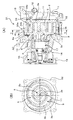
図1は、本発明の第1実施態様に係るスクロール型流体装置としてのスクロール型圧縮機を示している。図1に示すスクロール型圧縮機1においては、固定スクロール部材2の端板2a上には渦巻ラップ2bが一体に形成され、可動スクロール部材3の端板3a上には渦巻ラップ3bが一体に形成されている。両スクロール部材2、3は、両渦巻ラップ2b、3bの角度が互いにずれかつ両渦巻ラップ2b、3bの側壁が部分的に接触するように配設される。可動スクロール部材3は自転阻止機構4を介して自転を阻止された状態で円軌道上を公転運動され、両渦巻ラップ2b、3b間に形成される密閉された空間である流体ポケット5(一対で形成される流体ポケット)が渦巻ラップの外端部から中心部へ向けて移動されることにより(膨張機の場合には逆に中心部から外端部へ向けて移動される)流体ポケット5の容積を縮小される方向に変化され、渦巻ラップの外端部側から流体ポケット5内に取り込まれた流体(例えば、冷媒ガス)が圧縮されるようになっている。
FIG. 1 shows a scroll compressor as a scroll fluid device according to a first embodiment of the present invention. In the
圧縮機1のハウジングは、フロントハウジング6とリアハウジング7と、それらの間に配置されるセンターハウジング8とから構成されている。上記吸入流体は、本実施態様では、フロントハウジング6に設けられた吸入ポート9から吸入室10に導入され、そこから一部は後述の回廊状空間を経由して前述の流体ポケット5内に取り込まれ、圧縮に供される。圧縮された流体は、固定スクロール部材2の端板2aの中央部に穿設された吐出孔11を通して、リアハウジング7内に形成された吐出室12内に吐出され、そこから吐出ポート13を介して外部に排出される。
The housing of the
14は駆動軸を示しており、駆動軸14の一端側には、プーリ15に伝達されてきた回転駆動力が電磁クラッチ16を介して伝達され、それによって駆動軸14が回転駆動される。駆動軸14の他端側には、クランク機構17が構成されており、可動スクロール部材3が旋回運動するように駆動される。
固定スクロール部材2は、フロントハウジング6とリアハウジング7の間に配置されるセンターハウジング8の内部に該センターハウジング8と一体に形成されている。そして、この固定スクロール部材2の端板2aを高さ方向の位置の基準として、センターハウジング8の外殻シェル8aの端面8bの位置の高さが、固定スクロール部材2の渦巻ラップ2bの高さよりも低く設定されている。このセンターハウジング8の外殻シェル8a形成部と、フロントハウジング6の外殻6aの内面と、固定スクロール部材2の渦巻ラップ2bと、可動スクロール部材3の端板3aで囲まれた、装置周方向に延びる回廊状空間18が形成されている。この回廊状空間18は、本実施態様では、可動スクロール部材3の端板3aを挟んで固定スクロール部材2と反対側に位置している吸入室10に連通している。
The fixed
また、本実施態様では、センターハウジング8の外殻シェル8aの内面側に、固定スクロール部材2の渦巻ラップ2bの流体ポケット5の容積変化に寄与する壁面を形成する壁と、外殻シェル8aの外面を形成する壁との間に、固定スクロール部材2の渦巻ラップ2bの高さ方向と同じ方向に延びる有底の肉盗み部19が設けられている。本実施態様では、この肉盗み部19は、リアハウジング7側に向けて開口しており、リアハウジング7内に形成されている吐出室12に連通している。
Further, in this embodiment, a wall that forms a wall surface that contributes to the volume change of the
このように構成されたスクロール型圧縮機1においては、センターハウジング8の外殻シェル8aの端面8bの位置の高さを、固定スクロール部材2の渦巻ラップ2bの高さよりも低く設定することにより、固定スクロール部材2の渦巻ラップ2bの外周側において、フロントハウジング6の内面側の位置に、これまで全く注目されていなかった箇所を有効に利用して、装置周方向に延びる回廊状空間18を効率よく形成することができる。この回廊状空間18を介して、吸入室10から流体ポケット5内に吸入流体を取り込ませることが可能になり、吸入経路の途中に回廊状空間18を位置させることになるので、吸入圧損を低減することが可能になる。
In the
また、上記回廊状空間18は、装置軸方向に見て、センターハウジング8が占める部位の一部を利用して形成されることのなるので、残りの部位を利用して、この回廊状空間18に隣接させて図示のような肉盗み部19を形成することが可能になる。この肉盗み部19は、前述の従来のサブハウジングを設けて第2吐出室を設ける構造に比べ、特別装置外形を大きくすることなく形成可能なものである。したがって、このような従来構造に比べると、確実に小型軽量化をはかることが可能になる。図示例の肉盗み部19の形成により、実質的に吐出室12の容積を増やすことができるので、吐出脈動の低減を実現でき、それを介して騒音低減をはかることが可能になる。さらに、このような肉盗み部19の形成により、センターハウジング8に格別厚肉部が存在しないようにでき、各部の肉厚の均一化をはかることが可能になるので、センターハウジング8を鋳造等で成形する場合には、鋳巣などの欠陥の発生を防止することも可能になり、製造上、品質の安定化をはかることが可能になる。
Further, the
図2は、本発明の第2実施態様に係るスクロール型流体装置としてのスクロール型圧縮機を示している。図2に示すスクロール型圧縮機21においては、図1に示したスクロール型圧縮機1に比べ、センターハウジング22に形成される有底の肉盗み部23が、フロントハウジング24側に向けて開口している。この有底の肉盗み部23の開口側に連通するように、回廊状空間25が形成されている。そして本実施態様では、装置周方向に適当な長さをもって延びる肉盗み部23の横断面積が装置周方向において変化している構造とされ、例えば図2(B)における肉盗み部23の幅の狭い部位よりも幅の広い部位の方が深くなる形状に形成されている。肉盗み部23と回廊状空間25は開口部が対面するように連通されているので、実質的に回廊状空間25の横断面積が大きくなった形態とされ、かつ、その回廊状空間25の横断面積が装置周方向において変化している形態となる。その他の構成は前記第1実施態様に準じるので、図1に付したのと同一の符号を図2に付すことにより説明を省略する。
FIG. 2 shows a scroll compressor as a scroll fluid device according to a second embodiment of the present invention. In the
このように構成されたスクロール型圧縮機21においては、前記第1実施態様に比べ、適切に横断面積が変化されている回廊状空間25を介しての吸入流体の吸入をより円滑に行わせることが可能になり、吸入圧損の一層の低減をはかることが可能になる。
In the
図3は、本発明の第3実施態様に係るスクロール型流体装置としてのスクロール型圧縮機を示しており、本発明におけるセンターハウジングの、上述のような肉盗み部によるのとは別の軽量化形態とともに、回廊状空間と吸入ポートの断面積の関係について示している。図3に示すスクロール型圧縮機31においては、図1に示したスクロール型圧縮機1に比べ、センターハウジング32の外殻シェル32aの外面側に、固定スクロール部材2の渦巻ラップ2bの流体ポケット5の容積変化に寄与する壁面を形成する壁33aと、回廊状空間18に面する壁面を形成する壁33bとに対して、所定肉厚を持った外殻シェル32aの凹状外面34が形成されている構造とされている。このような構造においては、回廊状空間18に隣接させてセンターハウジング32の外殻シェル32aの外面に凹状外面34が形成されるので、この凹状外面34に対応する分、装置の小型化、軽量化をはかることが可能になる。
FIG. 3 shows a scroll compressor as a scroll type fluid device according to a third embodiment of the present invention. The center housing according to the present invention is lighter than the above-described meat stealer. Along with the form, the relationship between the corridor space and the cross-sectional area of the suction port is shown. In the
また、図3を利用して本発明における回廊状空間18と吸入ポート9の断面積の望ましい関係について説明する。すなわち、可動スクロール部材3が、その渦巻ラップ3b外周端内面とそれに対向する固定スクロール部材2の渦巻ラップ2b外面の距離が最大となる位相角の位置にあるときにおいて、回廊状空間の横断面積をA1、フロントハウジング6に設けられた吸入ポート9の断面積をA2とすると、
A2/2<A1<A2
の関係を満たしていることが好ましい。このような構成により、前述したように、適切な大きさの回廊状空間18により、円滑な吸入動作を確保でき、吸入圧損の低減をはかることができる。回廊状空間18を不要に大きくする必要がないから、装置全体の小型軽量化を促進できる。その他の構成は前記第1実施態様に準じるので、図1に付したのと同一の符号を図3に付すことにより説明を省略する。
A desirable relationship between the cross-sectional areas of the
A2 / 2 <A1 <A2
It is preferable that the relationship is satisfied. With such a configuration, as described above, a smooth suction operation can be ensured and the suction pressure loss can be reduced by the
図4は、本発明の第4実施態様に係るスクロール型流体装置としてのスクロール型圧縮機を示している。図4に示すスクロール型圧縮機41においては、図1に示したスクロール型圧縮機1に比べ、フロントハウジング42に、回廊状空間43に直接的に臨む吸入ポート44が設けられている。図4(B)における42aは、フロントハウジング42の内周を示している。このような構造においては、吸入ポート44から吸入された流体は常時そのまま直接的に回廊状空間43内に流入でき、そこから流体ポケット5内へと取り込まれるので、所望の吸入経路が常時安定的に形成され、安定した吸入動作が可能になる。その他の構成は前記第1実施態様に準じるので、図1に付したのと同一の符号を図4に付すことにより説明を省略する。
FIG. 4 shows a scroll compressor as a scroll fluid device according to a fourth embodiment of the present invention. In the
図5は、本発明の第5実施態様に係るスクロール型流体装置としてのスクロール型圧縮機を示している。図5に示すスクロール型圧縮機51においては、図4に示したスクロール型圧縮機41に比べ、リアハウジング7側に向けて開口しリアハウジング7内に形成された吐出室12と連通する肉盗み部19を設ける場合、肉盗み部19を圧縮機51の設置姿勢において下側に位置させ、肉盗み部19が、吐出室12内における油を貯留する貯油室52を形成するように構成されている。そして、貯油室52と吐出室12との間にはフィルター53が設けられており、フィルター53により、油戻りの際、異物等が流入することが防止されている。また、貯油室52と回廊状空間18とがオリフィス54(小孔)を介して連通されており、オリフィス54を通して、適切な量の油が吸入側、とくにその中の駆動部へと戻されるようになっている。このような構成においては、圧縮機をとくに大型化することなく実質的に吐出室12内に効率よく貯油空間が形成でき、貯留された油を適切に吸入側の駆動部に戻すことができるようになり、望ましい圧縮機の潤滑状態を得ることができる。その他の構成は前記第1実施態様に準じるので、図1に付したのと同一の符号を図5に付すことにより説明を省略する。
FIG. 5 shows a scroll compressor as a scroll fluid device according to a fifth embodiment of the present invention. In the
図6〜図8は、本発明の第6〜第8実施態様に係るスクロール型流体装置としてのスクロール型圧縮機を示している。図6〜図8に示すスクロール型圧縮機61、71、81においては、リアハウジング7側に向けて開口する有底の肉盗み部62、72、82が形成され、該肉盗み部62、72、82は、リアハウジング7内に形成された第1吐出室63、73、83(渦巻ラップにより圧縮された流体の吐出室)と絞り部64、74、84を介して連通する第2吐出室を形成している。吐出流体の経路に第1吐出室63、73、83に続きこのような第2吐出室62、72、82を形成しておくことにより、第2吐出室62、72、82に吐出経路における流体の脈動に対するバッファ機能、およびサイレンサー機能を持たせることができ、優れた吐出脈動低減、騒音低減効果を得ることが可能になる。
6 to 8 show a scroll type compressor as a scroll type fluid device according to sixth to eighth embodiments of the present invention. In the
図6に示すスクロール型圧縮機61においては、第2吐出室62から装置外部に圧縮流体を吐出する吐出ポート65は、センターハウジング66に設けられている。図7に示すスクロール型圧縮機71においては、第2吐出室72からの吐出ポート75がセンターハウジング76に設けられているとともに、上記絞り部74が、センターハウジング76とリアハウジング7との間のシールを行うガスケット77の内方輪郭と、第2吐出室72の開口部輪郭とによって形成されており、これによって、絞り部74形成のために特別な部材を付加することが不要化されている。図8に示すスクロール型圧縮機81においては、吐出ポート85が、センターハウジング86側ではなく、リアハウジング7側に設けられており、第2吐出室82からの流体が連通孔87を介して吐出ポート85から外部に排出されるようになっている。吐出ポートをいずれの位置に配置するかは、圧縮機の配置環境や、他の周囲機器との取り合い等に応じて適宜選択可能である。その他の構成は前記第1実施態様に準じるので、図1に付したのと同一の符号を図6〜図8に付すことにより説明を省略する。
In the
図9は、本発明の第9実施態様に係るスクロール型流体装置としてのスクロール型圧縮機を示している。図9に示すスクロール型圧縮機91においては、図4に示したスクロール型圧縮機41においてリアハウジング7側に向けて開口していた肉盗み部19が、図4に示したようにリアハウジング7内に形成された吐出室12に連通させるのではなく、吸入経路の一部として構成されている。すなわち、リアハウジング7内には、隔壁92を介して吐出室12と吸入室93が形成されており、該吸入室93が、上記肉盗み部19を経由して回廊状空間18と連通路94を介して連通している構造である。リアハウジング7には、吸入室93に連通する吸入ポート95が設けられているとともに、別の位置に吐出室12に連通する吐出ポート96が設けられている。このような構成は、とくに周囲の配置機器との関係からリアハウジング7に吸入ポート95と吐出ポート96の両方を設ける必要がある場合等に有効である。このような場合にあっても、回廊状空間18を流体ポケット5に流体が取り込まれる前の吸入圧損低減のための有効な空間として利用することができる。その他の構成は前記第1実施態様に準じるので、図1に付したのと同一の符号を図9に付すことにより説明を省略する。
FIG. 9 shows a scroll compressor as a scroll fluid device according to a ninth embodiment of the present invention. In the
図10は、本発明の第10実施態様に係るスクロール型流体装置としてのスクロール型圧縮機を示している。図10に示すスクロール型圧縮機101においては、図2に示したスクロール型圧縮機21におけるフロントハウジング24側に向けて開口されている有底の肉盗み部23が、吸入通路102の一部として形成されており、センターハウジング103に、肉盗み部23によって形成された吸入空間内に直接連通する吸入ポート104が設けられている。この肉盗み部23と回廊状空間25によって、効率よく吸入通路102を形成できる。このように、吸入通路102の形態も大きな自由度をもって設計可能である。その他の構成は前記第1実施態様に準じるので、図1に付したのと同一の符号を図10に付すことにより説明を省略する。
FIG. 10 shows a scroll compressor as a scroll fluid device according to a tenth embodiment of the present invention. In the
図11は、本発明の第11実施態様に係るスクロール型流体装置としてのスクロール型圧縮機を示している。図11に示すスクロール型圧縮機111は、図3に示したスクロール型圧縮機31と同様の構成を有しているが、この第11実施態様においては、圧縮機111を所定の場所に搭載するためのマウントボス112を、クラッチ部から、図示例ではプーリ15の位置からより遠くに配置している。つまり、プーリ15とマウントボス112との距離Lをより大きく設定している。逆に、Lをより小さくすることも可能である。このように、圧縮機111の搭載上の都合も勘案して、自由に設計することが可能である。その他の構成は前記第1実施態様に準じるので、図1に付したのと同一の符号を図11に付すことにより説明を省略する。
FIG. 11 shows a scroll compressor as a scroll fluid device according to an eleventh embodiment of the present invention. The
本発明に係るスクロール型流体装置の構成は、基本的にスクロール型圧縮機、スクロール型膨張機のいずれにも適用可能であり、とくに、吸入圧損の低減、吐出脈動低減、騒音低減、さらには小型軽量化の要求の強い車両空調装置用圧縮機に好適である。 The configuration of the scroll type fluid device according to the present invention is basically applicable to both a scroll type compressor and a scroll type expander, and in particular, reduction of suction pressure loss, reduction of discharge pulsation, reduction of noise, and further miniaturization. It is suitable for a compressor for a vehicle air conditioner that is strongly demanded for weight reduction.
1、21、31、41、51、61、71、81、91、101、111 スクロール型流体装置としてのスクロール型圧縮機
2 固定スクロール部材
2a 固定スクロール部材の端板
2b 固定スクロール部材の渦巻ラップ
3 可動スクロール部材
3a 可動スクロール部材の端板
3b 可動スクロール部材の渦巻ラップ
4 自転阻止機構
5 流体ポケット
6、24、42 フロントハウジング
7 リアハウジング
8、22、32、66、76、86、103 センターハウジング
8a、32a センターハウジングの外殻シェル
8b センターハウジング外殻シェルの端面
9、44、95、104 吸入ポート
10、93 吸入室
11 吐出孔
12 吐出室
13、65、75、85、96 吐出ポート
14 駆動軸
15 プーリ
16 電磁クラッチ
17 クランク機構
18、25、43 回廊状空間
19、23、62、72、82 肉盗み部
33a、33b 壁
34 凹状外面
42a フロントハウジングの内周
52 貯油室
53 フィルター
54 オリフィス
62、72、82 肉盗み部により形成された第2吐出室
63、73、83 第1吐出室
64、74、84 絞り部
77 ガスケット
87 連通孔
92 隔壁
94 連通路
102 吸入通路
112 マウントボス
1, 21, 31, 41, 51, 61, 71, 81, 91, 101, 111
Claims (20)
前記固定スクロール部材を、スクロール型流体装置のフロントハウジングとリアハウジングの間に配置されるセンターハウジングの内部に該センターハウジングと一体に形成するとともに、前記固定スクロール部材の端板を高さ方向の位置の基準として、前記センターハウジングの外殻シェルの端面の位置の高さを前記固定スクロール部材の渦巻ラップの高さよりも低くし、前記センターハウジングの外殻シェル形成部と、前記フロントハウジングの外殻の内面と、前記固定スクロール部材の渦巻ラップと、前記可動スクロール部材の端板で囲まれた、装置周方向に延びる回廊状空間を形成したことを特徴とするスクロール型流体装置。 A spiral wrap is integrally formed on the end plate of the fixed scroll member, and a spiral wrap is integrally formed on the end plate of the movable scroll member. A fluid pocket, which is a sealed space formed between both spiral wraps, is disposed so that the side walls are partially in contact with each other and revolves on a circular orbit while the movable scroll member is prevented from rotating. In the scroll type fluid device that changes the volume of the fluid pocket by moving the spiral wrap from the outer end portion toward the center portion or from the center portion toward the outer end portion,
The fixed scroll member is formed integrally with the center housing in a center housing disposed between the front housing and the rear housing of the scroll type fluid device, and the end plate of the fixed scroll member is positioned in the height direction. The height of the position of the end surface of the outer shell of the center housing is lower than the height of the spiral wrap of the fixed scroll member, and the outer shell forming part of the center housing and the outer shell of the front housing A scroll-type fluid device is characterized in that a corridor-like space extending in the circumferential direction of the device is formed, surrounded by an inner surface of the device, a spiral wrap of the fixed scroll member, and an end plate of the movable scroll member.
A2/2<A1<A2
の関係を満たしている、請求項1に記載のスクロール型流体装置。 A port in which the cross-sectional area A1 of the corridor space is provided in the front housing at a phase angle at which the distance between the spiral wrap outer peripheral end inner surface of the movable scroll member and the spiral wrap outer surface of the fixed scroll member facing the movable scroll member is maximum. For the cross-sectional area A2 of
A2 / 2 <A1 <A2
The scroll type fluid device according to claim 1, wherein the relationship is satisfied.
Priority Applications (5)
| Application Number | Priority Date | Filing Date | Title |
|---|---|---|---|
| JP2009238234A JP5421725B2 (en) | 2009-10-15 | 2009-10-15 | Scroll type fluid device |
| IN2607DEN2012 IN2012DN02607A (en) | 2009-10-15 | 2010-10-12 | |
| PCT/JP2010/006064 WO2011045921A1 (en) | 2009-10-15 | 2010-10-12 | Scroll fluidic device |
| US13/498,004 US20120263615A1 (en) | 2009-10-15 | 2010-10-12 | Scroll Fluidic Device |
| CN201080044204.5A CN102575672B (en) | 2009-10-15 | 2010-10-12 | Scroll fluidic device |
Applications Claiming Priority (1)
| Application Number | Priority Date | Filing Date | Title |
|---|---|---|---|
| JP2009238234A JP5421725B2 (en) | 2009-10-15 | 2009-10-15 | Scroll type fluid device |
Publications (3)
| Publication Number | Publication Date |
|---|---|
| JP2011085066A JP2011085066A (en) | 2011-04-28 |
| JP2011085066A5 JP2011085066A5 (en) | 2012-05-10 |
| JP5421725B2 true JP5421725B2 (en) | 2014-02-19 |
Family
ID=43875977
Family Applications (1)
| Application Number | Title | Priority Date | Filing Date |
|---|---|---|---|
| JP2009238234A Active JP5421725B2 (en) | 2009-10-15 | 2009-10-15 | Scroll type fluid device |
Country Status (5)
| Country | Link |
|---|---|
| US (1) | US20120263615A1 (en) |
| JP (1) | JP5421725B2 (en) |
| CN (1) | CN102575672B (en) |
| IN (1) | IN2012DN02607A (en) |
| WO (1) | WO2011045921A1 (en) |
Families Citing this family (4)
| Publication number | Priority date | Publication date | Assignee | Title |
|---|---|---|---|---|
| JP5782296B2 (en) * | 2011-05-13 | 2015-09-24 | サンデンホールディングス株式会社 | Scroll compressor |
| JP2016023612A (en) * | 2014-07-23 | 2016-02-08 | サンデンホールディングス株式会社 | Scroll type fluid machine |
| JP6444786B2 (en) * | 2015-03-20 | 2018-12-26 | 三菱重工サーマルシステムズ株式会社 | Scroll compressor |
| KR102238358B1 (en) * | 2017-03-15 | 2021-04-12 | 엘지전자 주식회사 | Rotary compressor |
Family Cites Families (11)
| Publication number | Priority date | Publication date | Assignee | Title |
|---|---|---|---|---|
| US4477238A (en) * | 1983-02-23 | 1984-10-16 | Sanden Corporation | Scroll type compressor with wrap portions of different axial heights |
| JPS60101295A (en) * | 1983-11-08 | 1985-06-05 | Sanden Corp | Compression capacity varying type scroll compressor |
| JP3206221B2 (en) * | 1993-06-15 | 2001-09-10 | 株式会社豊田自動織機製作所 | Scroll compressor |
| JP3144611B2 (en) * | 1993-10-15 | 2001-03-12 | 株式会社豊田自動織機製作所 | Scroll compressor |
| JP3582917B2 (en) * | 1995-12-06 | 2004-10-27 | 株式会社日本自動車部品総合研究所 | Scroll compressor |
| JP3882343B2 (en) * | 1998-06-12 | 2007-02-14 | 株式会社デンソー | Scroll compressor |
| JP2000087882A (en) * | 1998-09-11 | 2000-03-28 | Sanden Corp | Scroll type compressor |
| JP2001140775A (en) * | 1999-11-17 | 2001-05-22 | Sanden Corp | Scroll type compressor |
| JP2003013872A (en) * | 2001-06-28 | 2003-01-15 | Toyota Industries Corp | Scroll type compressor and its refrigerant compressing method |
| JP3918814B2 (en) * | 2004-01-15 | 2007-05-23 | ダイキン工業株式会社 | Fluid machinery |
| JP5067022B2 (en) * | 2007-06-04 | 2012-11-07 | 株式会社豊田自動織機 | Electric compressor |
-
2009
- 2009-10-15 JP JP2009238234A patent/JP5421725B2/en active Active
-
2010
- 2010-10-12 CN CN201080044204.5A patent/CN102575672B/en active Active
- 2010-10-12 IN IN2607DEN2012 patent/IN2012DN02607A/en unknown
- 2010-10-12 WO PCT/JP2010/006064 patent/WO2011045921A1/en active Application Filing
- 2010-10-12 US US13/498,004 patent/US20120263615A1/en not_active Abandoned
Also Published As
| Publication number | Publication date |
|---|---|
| WO2011045921A1 (en) | 2011-04-21 |
| US20120263615A1 (en) | 2012-10-18 |
| IN2012DN02607A (en) | 2015-09-04 |
| CN102575672A (en) | 2012-07-11 |
| CN102575672B (en) | 2015-09-02 |
| JP2011085066A (en) | 2011-04-28 |
Similar Documents
| Publication | Publication Date | Title |
|---|---|---|
| JP2007170253A (en) | Scroll compressor | |
| JP2009030469A (en) | Scroll compressor | |
| KR101133300B1 (en) | Rotary compressor | |
| JP5421725B2 (en) | Scroll type fluid device | |
| JP2005180295A (en) | Scroll compressor | |
| JP4992948B2 (en) | Scroll compressor | |
| WO2007077856A1 (en) | Compressor | |
| JP2005264827A (en) | Scroll compressor | |
| JP6633305B2 (en) | Scroll compressor | |
| JP4681322B2 (en) | Scroll compressor | |
| JP3408808B2 (en) | Scroll compressor | |
| JP4604968B2 (en) | Scroll compressor | |
| JP4690516B2 (en) | Scroll type fluid machinery | |
| JP5355361B2 (en) | Hermetic rotary compressor | |
| JP4408310B2 (en) | Scroll compressor | |
| JP4484912B2 (en) | Scroll compressor | |
| JP4844642B2 (en) | Scroll compressor | |
| WO2015008688A1 (en) | Scroll-type fluid machine and gasket therefor | |
| JP2008274877A (en) | Hermetic compressor | |
| JP3422744B2 (en) | Scroll compressor | |
| JP2006241993A (en) | Scroll compressor | |
| JP2019056336A (en) | Scroll type fluid machine | |
| JP5058919B2 (en) | Scroll type fluid machinery | |
| JP4301122B2 (en) | Scroll compressor | |
| JP4873036B2 (en) | Rotary compressor |
Legal Events
| Date | Code | Title | Description |
|---|---|---|---|
| A521 | Request for written amendment filed |
Free format text: JAPANESE INTERMEDIATE CODE: A523 Effective date: 20120321 |
|
| A621 | Written request for application examination |
Free format text: JAPANESE INTERMEDIATE CODE: A621 Effective date: 20120910 |
|
| TRDD | Decision of grant or rejection written | ||
| A01 | Written decision to grant a patent or to grant a registration (utility model) |
Free format text: JAPANESE INTERMEDIATE CODE: A01 Effective date: 20131029 |
|
| A61 | First payment of annual fees (during grant procedure) |
Free format text: JAPANESE INTERMEDIATE CODE: A61 Effective date: 20131122 |
|
| R150 | Certificate of patent or registration of utility model |
Ref document number: 5421725 Country of ref document: JP Free format text: JAPANESE INTERMEDIATE CODE: R150 |
|
| S533 | Written request for registration of change of name |
Free format text: JAPANESE INTERMEDIATE CODE: R313533 |
|
| R350 | Written notification of registration of transfer |
Free format text: JAPANESE INTERMEDIATE CODE: R350 |
|
| R250 | Receipt of annual fees |
Free format text: JAPANESE INTERMEDIATE CODE: R250 |
|
| R250 | Receipt of annual fees |
Free format text: JAPANESE INTERMEDIATE CODE: R250 |
|
| R250 | Receipt of annual fees |
Free format text: JAPANESE INTERMEDIATE CODE: R250 |
|
| R250 | Receipt of annual fees |
Free format text: JAPANESE INTERMEDIATE CODE: R250 |
|
| R250 | Receipt of annual fees |
Free format text: JAPANESE INTERMEDIATE CODE: R250 |
|
| R250 | Receipt of annual fees |
Free format text: JAPANESE INTERMEDIATE CODE: R250 |
|
| S533 | Written request for registration of change of name |
Free format text: JAPANESE INTERMEDIATE CODE: R313533 |
|
| R350 | Written notification of registration of transfer |
Free format text: JAPANESE INTERMEDIATE CODE: R350 |