JP5415349B2 - Micro component placement unit - Google Patents
Micro component placement unit Download PDFInfo
- Publication number
- JP5415349B2 JP5415349B2 JP2010099104A JP2010099104A JP5415349B2 JP 5415349 B2 JP5415349 B2 JP 5415349B2 JP 2010099104 A JP2010099104 A JP 2010099104A JP 2010099104 A JP2010099104 A JP 2010099104A JP 5415349 B2 JP5415349 B2 JP 5415349B2
- Authority
- JP
- Japan
- Prior art keywords
- shaft body
- pressing
- micro component
- placement unit
- shaft
- Prior art date
- Legal status (The legal status is an assumption and is not a legal conclusion. Google has not performed a legal analysis and makes no representation as to the accuracy of the status listed.)
- Active
Links
- 230000006837 decompression Effects 0.000 claims description 7
- 230000003028 elevating effect Effects 0.000 description 10
- 238000010586 diagram Methods 0.000 description 6
- 238000001179 sorption measurement Methods 0.000 description 5
- 238000000034 method Methods 0.000 description 4
- 230000003287 optical effect Effects 0.000 description 4
- 238000012856 packing Methods 0.000 description 4
- 230000002093 peripheral effect Effects 0.000 description 2
- 230000001174 ascending effect Effects 0.000 description 1
- 239000003990 capacitor Substances 0.000 description 1
- 239000002184 metal Substances 0.000 description 1
- 238000004377 microelectronic Methods 0.000 description 1
- 239000013585 weight reducing agent Substances 0.000 description 1
Images


Classifications
-
- H—ELECTRICITY
- H05—ELECTRIC TECHNIQUES NOT OTHERWISE PROVIDED FOR
- H05K—PRINTED CIRCUITS; CASINGS OR CONSTRUCTIONAL DETAILS OF ELECTRIC APPARATUS; MANUFACTURE OF ASSEMBLAGES OF ELECTRICAL COMPONENTS
- H05K13/00—Apparatus or processes specially adapted for manufacturing or adjusting assemblages of electric components
- H05K13/04—Mounting of components, e.g. of leadless components
- H05K13/0404—Pick-and-place heads or apparatus, e.g. with jaws
- H05K13/0408—Incorporating a pick-up tool
- H05K13/0409—Sucking devices
-
- H—ELECTRICITY
- H05—ELECTRIC TECHNIQUES NOT OTHERWISE PROVIDED FOR
- H05K—PRINTED CIRCUITS; CASINGS OR CONSTRUCTIONAL DETAILS OF ELECTRIC APPARATUS; MANUFACTURE OF ASSEMBLAGES OF ELECTRICAL COMPONENTS
- H05K13/00—Apparatus or processes specially adapted for manufacturing or adjusting assemblages of electric components
- H05K13/04—Mounting of components, e.g. of leadless components
- H05K13/0404—Pick-and-place heads or apparatus, e.g. with jaws
- H05K13/0408—Incorporating a pick-up tool
- H05K13/041—Incorporating a pick-up tool having multiple pick-up tools
-
- H—ELECTRICITY
- H05—ELECTRIC TECHNIQUES NOT OTHERWISE PROVIDED FOR
- H05K—PRINTED CIRCUITS; CASINGS OR CONSTRUCTIONAL DETAILS OF ELECTRIC APPARATUS; MANUFACTURE OF ASSEMBLAGES OF ELECTRICAL COMPONENTS
- H05K13/00—Apparatus or processes specially adapted for manufacturing or adjusting assemblages of electric components
- H05K13/04—Mounting of components, e.g. of leadless components
- H05K13/0404—Pick-and-place heads or apparatus, e.g. with jaws
- H05K13/0413—Pick-and-place heads or apparatus, e.g. with jaws with orientation of the component while holding it; Drive mechanisms for gripping tools, e.g. lifting, lowering or turning of gripping tools
Landscapes
- Engineering & Computer Science (AREA)
- Manufacturing & Machinery (AREA)
- Microelectronics & Electronic Packaging (AREA)
- Supply And Installment Of Electrical Components (AREA)
- Specific Conveyance Elements (AREA)
Description
本発明は、電子部品をプリント配線板の表面に実装する電子部品実装装置に組み込んで特に有利に用いることができる微小部品配置ユニットに関する。 The present invention relates to a micro component placement unit that can be used particularly advantageously by being incorporated in an electronic component mounting apparatus for mounting electronic components on the surface of a printed wiring board.
従来より、電子部品をプリント配線板の表面に実装するため電子部品実装装置が用いられている。電子部品実装装置には通常、下端に電子部品(微小部品)の吸着ノズルを備える軸体と、この軸体の昇降駆動装置とを備える微小部品配置ユニットが組み込まれている。 Conventionally, an electronic component mounting apparatus has been used to mount an electronic component on the surface of a printed wiring board. In general, an electronic component mounting apparatus incorporates a micro component placement unit including a shaft body provided with a suction nozzle for electronic components (micro components) at the lower end and an elevating drive device for the shaft body.
電子部品実装装置の作動に際しては、先ず上記微小部品配置ユニットを、電子部品が収容されたトレイの上方に移動させる。微小部品配置ユニットは、軸体を下降させ、その下端に備えられた吸着ノズルにより電子部品を吸着したのち軸体を上昇させる。次いで電子部品実装装置は、微小部品配置ユニットを、プリント配線板の上方に移動させる。そして微小部品配置ユニットは、軸体を下降させ、その吸着ノズルに吸着している電子部品をプリント配線板の表面に配置(実装)したのち軸体を上昇させる。このような操作を繰り返すことにより、プリント配線板の表面に多数の電子部品が実装される。 In the operation of the electronic component mounting apparatus, first, the micro component placement unit is moved above the tray in which the electronic components are accommodated. The micro component placement unit lowers the shaft body, lifts the shaft body after sucking the electronic component by the suction nozzle provided at the lower end thereof. Next, the electronic component mounting apparatus moves the micro component placement unit above the printed wiring board. The micro component placement unit lowers the shaft body, and after placing (mounting) the electronic component sucked by the suction nozzle on the surface of the printed wiring board, the shaft body is raised. By repeating such an operation, a large number of electronic components are mounted on the surface of the printed wiring board.
プリント配線板の表面に多数の電子部品を効率良く(短時間で)実装するため、微小部品配置ユニットは、通常、各々下端に吸着ノズルを持つ軸体が複数本備えられた構成とされ、この微小部品配置ユニットの高速での移動が繰り返して行なわれる。 In order to mount a large number of electronic components on the surface of the printed wiring board efficiently (in a short time), the micro component placement unit is usually configured with a plurality of shaft bodies each having a suction nozzle at the lower end. The micro component placement unit is repeatedly moved at high speed.
特許文献1には、各々下端に吸着ノズルを持つ複数本(例、10本)の軸体(駆動シャフト)を備える微小部品配置ユニット(ヘッドユニット)が開示されている。複数本の軸体のそれぞれを独立に昇降可能とするため、各軸体毎に昇降駆動装置(リニアモータ)が備えられている。 Patent Document 1 discloses a micro component placement unit (head unit) including a plurality (for example, 10) of shaft bodies (drive shafts) each having a suction nozzle at the lower end. In order to allow each of the plurality of shaft bodies to be lifted and lowered independently, a lift driving device (linear motor) is provided for each shaft body.
特許文献2には、各々下端に吸着ノズルを持つ複数本(例、8本)の軸体(スピンドル)を備える微小部品配置ユニット(部品移載装置)が開示されている。複数本の軸体は、円盤状のロータリヘッドの周縁部に装着されている。ロータリヘッドには回転駆動装置(サーボモータ43)が接続されている。この回転駆動装置を作動させることにより、ロータリヘッドが回転(自転)する。これにより、複数本の軸体もまた回転(ロータリヘッドの回転軸を中心として公転)する。微小部品配置ユニットには、昇降駆動装置(サーボモータ45、送りねじ46及び下降レバー47)が備えられている。この昇降駆動装置を作動させることにより、上記ロータリヘッドの回転によって昇降駆動装置の下降レバーの下に配置された軸体が下降する。 Patent Document 2 discloses a micro component placement unit (component transfer device) including a plurality of (for example, eight) shaft bodies (spindles) each having a suction nozzle at the lower end. The plurality of shafts are attached to the peripheral edge of the disk-shaped rotary head. A rotary drive device (servo motor 43) is connected to the rotary head. By operating this rotational drive device, the rotary head rotates (spins). As a result, the plurality of shaft bodies also rotate (revolve around the rotation axis of the rotary head). The micro component placement unit is provided with an elevating drive device (servo motor 45, feed screw 46, and lowering lever 47). By operating this lifting drive, the shaft disposed under the lowering lever of the lifting drive is lowered by the rotation of the rotary head.
微小部品配置ユニットは、その高速での移動が繰り返して行なわれるため、簡単な構成を有していて、かつ軽量であることが望ましい。微小部品配置ユニットの質量が大きいと、微小部品配置ユニットの高速での移動を開始あるいは停止する際に生じる慣性により、その移動の精度(位置決めの精度)が低下することがあり、また移動のために必要とされる消費電力も大きくなる。 Since the micro component placement unit is repeatedly moved at a high speed, it is desirable that the micro component placement unit has a simple configuration and is lightweight. If the mass of the micro component placement unit is large, the accuracy of the movement (positioning accuracy) may be reduced due to the inertia that occurs when the micro component placement unit starts or stops moving at high speed. The power consumption required for this is also increased.
特許文献1の微小部品配置ユニットは、その各軸体毎に昇降駆動装置(合計で10台のリニアモータ)を備える複雑な構成を有しているため、これを軽量化することは容易ではない。 Since the micro component placement unit of Patent Document 1 has a complicated configuration including a lifting drive device (total of 10 linear motors) for each shaft body, it is not easy to reduce the weight thereof. .
特許文献2の微小部品配置ユニットは、ロータリヘッドにより複数本の軸体を回転(公転)させる複雑な構成を有しているため、これを軽量化することは容易ではない。また、各軸体が回転(公転)により水平方向に移動するため、ロータリヘッドを回転させて高精度にて位置決めしないと、軸体の吸着ノズルに吸着させた電子部品の位置が変動する。ロータリヘッドを高精度の回転駆動装置を用いて回転させることもできるが、このような回転駆動装置は複雑な構成を有していて、微小部品配置ユニットの質量を増加させる傾向にある。 Since the micro component placement unit of Patent Document 2 has a complicated configuration in which a plurality of shafts are rotated (revolved) by a rotary head, it is not easy to reduce the weight. Further, since each shaft body moves in the horizontal direction by rotation (revolution), the position of the electronic component sucked by the suction nozzle of the shaft body fluctuates unless the rotary head is rotated and positioned with high accuracy. Although the rotary head can be rotated using a high-precision rotary drive device, such a rotary drive device has a complicated configuration and tends to increase the mass of the micro component placement unit.
本発明の課題は、構成が簡単で軽量化も容易な微小部品配置ユニットを提供することにある。 An object of the present invention is to provide a micro component placement unit that is simple in configuration and easy in weight reduction.
本発明は、減圧機構に接続する微小部品吸着ノズルを下端に備えた軸体および軸体の周囲に備えられた軸体の昇降を案内する軸受からなる微小部品の昇降手段が複数個、それぞれの軸体の頂部および吸着ノズルの下端部を、それぞれが同一の高さにあるような位置関係にて軸体の幅方向に整列配置してなる微小部品の昇降機構、昇降機構を支持固定している枠体、各昇降手段の軸体と軸受あるいは枠体とに係合して軸体をその頂部の高さが全て所定の高さになるように支持する弾性体、各軸体の頂部の上方に間隔を介して配置された押圧装置、任意の軸体の頂部と押圧装置の底面との間の間隔に挿入することが可能にされている押圧補助部材、そして押圧補助部材に接続し、この押圧補助部材を駆動して水平方向の移動かつ位置決めを行なう押圧補助部材駆動機構を含む微小部品配置ユニットにある。 The present invention comprises a plurality of micropart raising / lowering means each comprising a shaft body provided with a micropart suction nozzle connected to a decompression mechanism at the lower end and a bearing for guiding the shaft body provided around the shaft body. Supporting and fixing the lifting mechanism and lifting mechanism for micro parts, in which the top part of the shaft body and the lower end part of the suction nozzle are aligned in the width direction of the shaft body in such a positional relationship that they are at the same height. A frame body, an elastic body that engages the shaft body of each lifting means and the bearing or the frame body, and supports the shaft body so that the height of all the tops thereof is a predetermined height, and the top of each shaft body Connected to a pressing device disposed above a space between the top of the arbitrary shaft body and the space between the bottom surface of the pressure device, and a pressure assisting member that can be inserted into the space between the bottom surface of the pressure device, This pressing assist member is driven to move and position in the horizontal direction. In microcomponents deployment unit comprising a pressure support member drive mechanism.
本発明の微小部品配置ユニットの好ましい態様は、次の通りである。
(1)押圧補助部材が、円盤状部材と円盤状部材を回転可能に保持する移動部材とからなり、そして押圧補助部材駆動機構が環状ベルトと環状ベルトの循環移動を実現する駆動装置とからなる。
(2)微小部品吸着ノズルが接続する減圧機構が、中空とした軸体の内部空間を介して微小部品吸着ノズルに接続している。
(3)各軸体が軸受内にて回転可能とされている。
The preferable aspect of the micro component placement unit of the present invention is as follows.
(1) The pressing auxiliary member includes a disk-shaped member and a moving member that rotatably holds the disk-shaped member, and the pressing auxiliary member driving mechanism includes an annular belt and a driving device that realizes circular movement of the annular belt. .
(2) The pressure reducing mechanism to which the micro component suction nozzle is connected is connected to the micro component suction nozzle through the hollow internal space of the shaft body.
(3) Each shaft body is rotatable in the bearing.
本発明の微小部品配置ユニットは、各軸体毎に昇降駆動装置を設ける必要がないため、その構成が簡単で軽量化も容易である。 Since the micro component placement unit of the present invention does not need to be provided with an elevating drive device for each shaft body, the configuration is simple and the weight can be easily reduced.
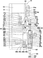
本発明の微小部品配置ユニットを、添付の図面を用いて説明する。図1は、本発明の微小部品配置ユニット10の構成例を示す正面図である。そして図2は、図1の微小部品配置ユニット10の左側面図である。なお、上記の図1において、電子部品91a〜91f、電子部品を収容するトレイ92、軸体13a〜13fの各々の周囲に装着されている環状のパッキン18、そして昇降機構15を支持固定している枠体16は、それぞれ断面として記入してある。また、枠体16の図の紙面に対して手前側に備えられている接続具(図2:11)は記入されていない。
The micro component placement unit of the present invention will be described with reference to the accompanying drawings. FIG. 1 is a front view showing a configuration example of a micro
図1及び図2に示す微小部品配置ユニット10は、減圧機構に接続する微小部品吸着ノズル(例、吸着ノズル12a)を下端に備えた軸体(例、軸体13a)および軸体の周囲に備えられた軸体の昇降を案内する軸受14からなる微小部品の昇降手段(例、昇降手段15a)が複数個、それぞれの軸体の頂部および吸着ノズルの下端部を、それぞれが同一の高さにあるような位置関係にて軸体の幅方向に整列配置してなる微小部品の昇降機構15、昇降機構15を支持固定している枠体16、各昇降手段の軸体と枠体16とに係合して軸体をその頂部の高さが全て所定の高さになるように支持する弾性体17、各軸体の頂部の上方に間隔を介して配置された押圧装置51、任意の軸体の頂部と押圧装置51の底面との間の間隔に挿入することが可能にされている押圧補助部材61、そして押圧補助部材61に接続し、押圧補助部材61を駆動して水平方向の移動かつ位置決めを行なう押圧補助部材駆動機構71から構成されている。
1 and 2 includes a shaft body (e.g.,
微小部品配置ユニット10は、例えば、その支持板19が電子部品実装装置が備える駆動装置に接続固定された状態にて電子部品実装装置に組み込まれる。この駆動装置の作動により、例えば、複数個の電子部品を収容しているトレイ92とプリント配線板(図11:93)との間での微小部品配置ユニット10の高速での移動が繰り返して行なわれる。
For example, the micro
微小部品配置ユニット10には、例えば、昇降手段15a〜15fの六個が備えられている。昇降手段の個数(すなわち微小部品吸着ノズルを備える軸体の本数に相当する)は、通常は2〜30個、好ましくは3〜20個の範囲内、更に好ましくは4〜10個の範囲内に設定される。
The micro
昇降手段15aは、減圧機構(図示していない)に接続する微小部品吸着ノズル12a、軸体13a、および軸受14から構成されている。昇降手段15b〜15fの各々の構成は、昇降手段15aと同様である。以下では、昇降手段15a〜15fの構成や動作を、昇降手段15aを代表例として説明する。
The raising / lowering means 15a is comprised from the micro component adsorption |
減圧機構は、枠体16に備えられた接続具11の管体11aに接続される。減圧機構としては、例えば、エゼクタ真空ポンプに代表される公知のポンプ(図示していない)を用いることができる。
The decompression mechanism is connected to the tube 11 a of the connector 11 provided in the
減圧機構は、微小部品吸着ノズルに接続されていてもよいが、図2に示すように、中空とした軸体13aの内部空間22を介して微小部品吸着ノズル12aに接続されていることが好ましい。このような接続方法を採用すると、電子部品91aを吸着するため軸体13aを微小部品吸着ノズル12aと共に昇降させた際に、この吸着ノズル12aと共に減圧機構が昇降することがないため、軸体13aの円滑な昇降が実現される。
The decompression mechanism may be connected to the minute component suction nozzle, but as shown in FIG. 2, it is preferably connected to the minute
減圧機構のポンプを作動させて軸体13aの内部空間22を減圧することにより、微小部品吸着ノズル12aの下端に電子部品を吸着させることができる。軸体13aの内部空間22を減圧するため、軸体13aには内部空間22に接続する孔23が形成されている。そして孔23の上下の各々において、軸体13aの周囲には環状のパッキン18が装着されている。このポンプの作動を停止して軸体13aの内部空間を外気圧と等しくする(あるいは外気圧よりも高い圧力にする)ことにより、微小部品吸着ノズル12aの下端から電子部品を離脱させることができる。
By operating the pump of the decompression mechanism to decompress the
微小部品吸着ノズル12aを備える軸体13aの周囲には、軸体13aの昇降を案内する軸受14が備えられている。軸受14としては、公知の直動軸受(例、ボールブッシュ)が用いられている。
Around the
昇降手段15a〜15fは、それぞれの軸体の頂部および吸着ノズルの下端部を、それぞれが同一の高さにあるような位置関係にて軸体の幅方向に整列配置されていて、微小部品の昇降機構15を構成している。昇降機構15は、各昇降手段の軸受14を介して枠体16に支持固定されている。枠体16は(接続部材24と回転駆動装置83とを介して)支持板19に固定されている。
The elevating means 15a to 15f are arranged such that the top of each shaft body and the lower end of the suction nozzle are aligned in the width direction of the shaft body in such a positional relationship that they are at the same height. An elevating
微小部品配置ユニット10には、各昇降手段の軸体と枠体16とに係合して軸体をその頂部の高さが全て所定の高さになるように支持する弾性体17が備えられている。弾性体17としては、コイルばねが用いられている。コイルばねに代えて、例えば、ゴム製の筒体などを用いることもできる。なお、上記の「所定の高さ」とは、軸体を下降させた際に微小部品吸着ノズルの下端が電子部品(微小部品)に到達可能な高さを意味し、微小部品配置ユニットが組み込まれる装置に応じて適切な高さに設定される。
The micro
例えば、軸体13aをその頂面を押圧して下降させると、軸体13aと枠体16とに係合している弾性体17が短縮する。従って、上記の軸体13aへの押圧を停止すると、弾性体17が伸長して軸体13aが上昇する。
For example, when the
上記弾性体は、軸体と軸受(例、軸受14)とに係合していてもよい。上記弾性体と、軸体そして枠体(あるいは軸受)との係合については、後に詳しく説明する。 The elastic body may be engaged with a shaft body and a bearing (eg, bearing 14). The engagement between the elastic body, the shaft body, and the frame body (or bearing) will be described in detail later.
複数本の軸体13a〜13fを昇降させるため、各軸体の頂部の上方に間隔を介して押圧装置51が配置される。
In order to move up and down the plurality of
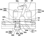
押圧装置51は、複数本の軸体13a〜13fの上方に昇降可能に配設されている、各軸体の上端面に対向する底面を有する可動ブロック52、可動ブロック52の上方に配設されていて、可動ブロック52の底面に対して平行に配置された回転軸53aを持つ回転駆動装置53、および回転駆動装置53の回転軸53aの中心とは異なる位置に一方の端部が接続され、他方の端部が可動ブロック52の側面(あるいは頂面)に接続されている、上記各端部を中心とする傾斜移動が可能なロッド54から構成されている。
The
可動ブロック52と回転駆動装置53に備えられたプレート55とは、直動案内装置(リニアガイド)56、56を介して互いに接続されている。各直動案内装置56は、上下方向に伸びるレール56aとレール56aに滑動可能に装着されたスライダ56bとから構成されている。可動ブロック52は、各直動案内装置56のスライダ56bと共にレール56aに沿って移動(昇降)可能とされている。
The
回転駆動装置53の回転軸53aを図1に記入した矢印59aが示す方向(時計回り方向)に回転させると、ロッド54が可動ブロック52を押し下げ、これにより可動ブロック52が直動案内装置56のスライダ56bと共に下降する。一方、回転駆動装置53の回転軸53aを上記とは逆向き(図1にて反時計回り方向)に回転させると、ロッド54が可動ブロック52を引き上げ、これにより可動ブロック52は直動案内装置56のスライダ56bと共に上昇する。
When the
押圧装置51は、部品点数が少ないため、構成が簡単で軽量化が容易であるという利点を有している。なお、押圧装置51の回転駆動装置53及びロッド54は、可動ブロック52を上下方向に移動(昇降)させる直動駆動装置として機能している。この回転駆動装置53及びロッド54に代えて、公知の直動駆動装置を用いることができる。直動駆動装置の例としては、リニアモータ、あるいは回転駆動装置と送りねじとを組み合わせた直動駆動装置が挙げられる。
Since the
微小部品配置ユニット10には、軸体13a〜13fのうちの任意の軸体の頂部と、押圧装置51の底面(すなわち可動ブロック52の底面)との間の間隔に挿入することが可能にされている押圧補助部材61と、押圧補助部材61に接続し、押圧補助部材61を駆動して水平方向の移動かつ位置決めを行なう押圧補助部材駆動機構71とが備えられている。
The micro
図1及び図2において、押圧補助部材61は、例えば、軸体13aの頂部と押圧装置51の底面との間の間隔(間隙)に挿入された状態にて示されている。
1 and 2, the pressing assisting
押圧補助部材61を支持しているプレート62aは、直動案内装置63に固定されている。直動案内装置63は、上下方向に伸びるレール63aとレール63aに滑動可能に装着されたスライダ63bとから構成されている。レール63aはプレート62bに固定されていて、そしてスライダ63bはプレート62aに固定されている。プレート62aの下端面にはプレート62cが固定されている。プレート62b、62cは、弾性体64、64を介して互いに接続されている。弾性体64としては、例えば、コイルばねが用いられている。
The
従って、押圧装置51の可動ブロック52を下降させることにより、押圧補助部材61は、可動ブロック52に押されて(押圧されて)、プレート62a、62c、およびスライダ63bと共にレール63aに沿って下方に移動(下降)する。この際、プレート62bとプレート62cとを接続している弾性体64が伸長する。このため、可動ブロック52を上昇させることにより、弾性体64が短縮して、押圧補助部材61は、プレート62a、62c、およびスライダ63bと共にレール63aに沿って上方に移動(上昇)する。このような機構により、押圧補助部材61の昇降が可能とされている。
Therefore, by lowering the
一方、上記の直動案内装置63を支持しているプレート62bは、別の直動案内装置65に固定されている。直動案内装置65は、水平方向に(軸体13a〜13fの整列方向に沿って)伸びるレール65aとレール65aに滑動可能に装着されたスライダ65bとから構成されている。レール65aは、支持板19から水平方向に伸びる棚板21の端面に固定されている。
On the other hand, the
従って、押圧補助部材61は、プレート62a、62c、直動案内装置63、プレート62b、および直動案内装置65のスライダ65bと共にレール65aに沿って水平方向に(軸体13a〜13fの整列方向に沿って)移動することが可能とされている。
Accordingly, the pressing
押圧補助部材駆動機構71は、環状ベルト72と環状ベルト72の循環移動を実現する駆動装置73とから構成されている。
The pressing assisting
駆動装置73は、回転軸74aを持つ回転駆動装置(例、モータ)74、回転軸74aに接続するプーリ75a、そして別の四個のプーリ75b〜75eから構成されている。
The
環状ベルト72としては、タイミングベルトが用いられていて、環状ベルト72の内面を支持しているプーリ75a〜75cとしては、タイミングプーリが用いられている。
A timing belt is used as the
環状ベルト72は、例えば、L字型の接続部材76を介して、上記押圧補助部材61を支持しているプレート62bに接続されている。従って、回転駆動装置74の回転軸74aを回転(あるいは逆回転)させ、環状ベルト72を循環移動させることにより、環状ベルト72に接続部材を介して接続している押圧補助部材61を、水平方向に移動して位置決めすることができる。
The
環状ベルトを利用した押圧補助部材駆動機構71は、構成が簡単で軽量化が容易であるという利点を有している。なお、押圧補助部材駆動機構71は、押圧補助部材61を水平方向に移動させる直動駆動装置として機能している。この押圧補助部材駆動機構71に代えて、公知の直動駆動装置を用いることができる。直動駆動装置の例としては、リニアモータ、あるいは回転駆動装置と送りねじとを組み合わせた直動駆動装置が挙げられる。
The pressing assist
次に、押圧補助部材61の動作の一例について、添付の図3〜図5を参照しながら説明する。図3〜図5には、図1及び図2に示す微小部品配置ユニット10の押圧装置51、押圧補助部材61、そして押圧補助部材駆動機構71が記入してある。
Next, an example of the operation of the pressing assisting
図3に示すように、押圧補助部材駆動機構71の回転駆動装置(図2:74)を作動させ、その回転軸に接続されたプーリ75aを、例えば、矢印79aが示す向きに回転させることにより、環状ベルト72を、矢印79bが示す方向に循環移動させる。これにより、押圧補助部材61が、矢印69aが示す方向(図にて右方向)に移動する。そして押圧補助部材61が任意の軸体の頂部の上方に移動したのち、上記回転駆動装置の作動を停止することにより、押圧補助部材61の水平方向の位置決めを行なうことができる。
As shown in FIG. 3, by operating the rotation driving device (FIG. 2: 74) of the pressing assisting
図4は、上記の位置決めの操作により、押圧補助部材61が、例えば、図1に示す軸体13bの頂部の上方に位置決めされた状態を示している。
FIG. 4 shows a state where the pressing assisting
そして図4に示すように、押圧装置51の回転駆動装置(図2:53)を作動させ、その回転軸53aを矢印59aが示す方向に回転させることにより、可動ブロック52を下降させる。この可動ブロック52に押圧されて、押圧補助部材61が矢印69bが示す方向に移動(下降)する。
Then, as shown in FIG. 4, the rotary drive device (FIG. 2: 53) of the
図5は、押圧補助部材61が下降した状態を示している。押圧補助部材61は、前記のように図1に示す軸体13bの頂部の上方に位置決めされている。このため、前記のように押圧補助部材61を下降させることにより、図1に示す軸体13bが微小部品吸着ノズル12bと共に下降する。そして押圧補助部材61を上昇させることにより、軸体13bを支持している弾性体17が伸長して、軸体13bもまた上昇する。
FIG. 5 shows a state where the
従って、図1及び図2に示す微小部品配置ユニット10は、押圧補助部材駆動機構71を用いて押圧補助部材61を任意の軸体の頂部の上方に移動させて位置決めを行ない、次いで押圧装置51を用いて押圧補助部材61を昇降させることにより、この軸体をその下端に備えられた微小部品吸着ノズルと共に選択的に昇降させることができるため、すなわち各軸体毎に昇降駆動装置を設ける必要がないため、その構成が簡単で軽量化も容易である。
Accordingly, the micro
また、複数本の軸体13a〜13fはそれぞれ枠体16に固定されていて、各軸体が水平方向に移動することがないため、軸体を水平方向に移動させて高精度にて位置決めする駆動装置を用いる必要もない。
Further, since the plurality of
次に、微小部品配置ユニット10の使用方法、例えば、トレイ92に収容された電子部品91a〜91fをプリント配線板の表面に配置(実装)する方法について説明する。
Next, a method of using the micro
先ず、図1に示すように、押圧補助部材駆動機構71により押圧補助部材61を水平方向に移動して、軸体13aの頂部の上方に位置決めする。これにより、押圧補助部材61は、押圧装置51の底面(すなわち可動ブロック52の底面)と軸体13aの頂部との間の間隔(間隙)に挿入される。
First, as shown in FIG. 1, the pressing auxiliary
次に、押圧装置51の可動ブロック52を押圧補助部材61と共に下降させることにより、図6に示すように軸体13aを微小部品吸着ノズル12aと共に下降させる。微小部品吸着ノズル12aの下端が電子部品91aに到達したのち減圧機構を作動させることにより、吸着ノズル12aの下端に電子部品91aを吸着させる。次いで、押圧装置51の可動ブロック52を上昇させることにより、押圧補助部材61が上昇し、そして図7に示すように、軸体13aが電子部品91aを吸着させた微小部品吸着ノズル12aと共に上昇する。このようにして、一個目の電子部品91aの吸着が行なわれる。
Next, by lowering the
続いて、押圧補助部材駆動機構71により押圧補助部材61を水平方向に移動して、図8に示すように軸体13bの頂部の上方に位置決めする。そして前記と同様にして押圧装置51の可動ブロック52を押圧補助部材61と共に下降させることにより、図9に示すように軸体13bを微小部品吸着ノズル12bと共に下降させる。微小部品吸着ノズル12bの下端が電子部品91bに到達したのち減圧機構を作動させることにより、吸着ノズル12bの下端に電子部品91bを吸着させる。次いで、押圧装置51の可動ブロック52を上昇させることにより、押圧補助部材61が上昇し、軸体13bが電子部品91bを吸着させた微小部品吸着ノズル12bと共に上昇する。このようにして、二個目の電子部品91bの吸着が行なわれる。
Subsequently, the pressing auxiliary
同様の操作を繰り返すことにより、図10に示すように微小部品吸着ノズル12a〜12fに、それぞれ電子部品91a〜91fを吸着させる。
By repeating the same operation, the electronic components 91a to 91f are attracted to the minute
そして、図11に示すように微小部品配置ユニット10をプリント配線板93の上方に移動したのち、例えば、軸体13fを微小部品吸着ノズル12fと共に下降させることにより、プリント配線板93の表面に電子部品91fを配置(実装)することができる。同様にして、残りの電子部品をプリント配線板93の表面に配置する。
Then, as shown in FIG. 11, after the micro
図2に示すように、押圧補助部材61は、円盤状部材61aと円盤状部材61aを回転可能に保持する移動部材61bとから構成されていることが好ましい。このような押圧補助部材61としては、例えば、軸付きローラ、軸の周囲に回転軸受を装着した部品、あるいはカム機構に利用されるカムフォロアを用いることができる。
As shown in FIG. 2, it is preferable that the
押圧補助部材61が円盤状部材61aと移動部材61bとから構成されていると、押圧補助部材61が水平方向に移動する際に、円盤状部材61aが押圧装置51の底面(すなわち可動ブロック52の底面)に接触しながら転動する。これにより、押圧補助部材61と押圧装置51との摩擦が極めて小さくなるため、押圧補助部材61の耐久性が良好となる。
When the pressing
なお、押圧装置を押圧補助部材の上方に間隙を介して配置して、押圧補助部材を押圧装置と接触させることなく水平方向に移動させて位置決めすることもできる。このような場合には、押圧補助部材を、例えば、金属製の部材から構成することもできる。 It is also possible to position the pressing device above the pressing assisting member via a gap and move the pressing assisting member in the horizontal direction without contacting the pressing device. In such a case, the pressing assisting member can be constituted by, for example, a metal member.
また、本発明の微小部品配置ユニットにおいては、微小部品吸着ノズルに吸着された微小部品(例、電子部品)が所定の向きに配置されるように、各軸体が軸受内にて回転可能とされていることが好ましい。 Moreover, in the micro component placement unit of the present invention, each shaft body can be rotated in the bearing so that the micro components (eg, electronic components) sucked by the micro component suction nozzle are arranged in a predetermined direction. It is preferable that
図1及び図2に示す微小部品配置ユニット10の各軸体、例えば、軸体13aは、その昇降と回転とが可能な状態にて軸受14に支持されている。
Each shaft body, for example, the
各軸体を回転駆動するため、各軸体の周囲には軸受81が更に備えられている。軸受81としては、軸体を昇降可能に且つ非回転の状態にて支持する公知の軸受を用いることができる。例えば、各軸体の外周面に互いに周方向に間隔をあけて複数本の直線溝を形成し、そして各直線溝との係合により軸体を昇降可能に且つ非回転の状態にて支持するスプライン軸受を用いることができる。
In order to rotationally drive each shaft body, a
各軸受81の周囲には回転軸受82が装着されていて、軸受81を軸体と共に回転することが可能とされている。そして軸体13a〜13fには、それぞれ軸受81を介してプーリ84a〜84fが備えられている。
A
一方、微小部品配置ユニット10には、回転駆動装置83が備えられている。回転駆動装置83の回転軸83aにはプーリ85aが備えられている。
On the other hand, the micro
プーリ85aは、環状ベルト86aを介してプーリ85bに接続されている。プーリ85bは、その回転軸87を介してプーリ85cに接続されている。プーリ85cは、環状ベルト86bを介してプーリ84a、84bに、そして環状ベルト86cを介してプーリ84b、84cに、それぞれ接続されている。
The
プーリ85aは、同様にして環状ベルト86dを介してプーリ85dに接続されている。プーリ85dにその回転軸を介して接続されたプーリ(図示していない)は、環状ベルト86eを介してプーリ84d、84eに、そして環状ベルト86fを介してプーリ84e、84fに、それぞれ接続されている。
The
従って、回転駆動装置83を駆動して、その回転軸83aを回転させ、これによりプーリ84a〜84fを回転させることにより、軸体13a〜13fをそれぞれ軸受81に支持された状態にて同時に回転させることができる。
Accordingly, the
回転駆動装置83に代えて、二個の回転駆動装置を設け、一方の回転駆動装置の回転軸にプーリ及びベルトを介してプーリ84a、84c、84eを接続し、そして他方の回転駆動装置の回転軸にプーリ及びベルトを介してプーリ84b、84d、84fを接続することもできる。すなわち、一方の回転駆動装置により、軸体13a、13c、13eを同時に回転駆動し、そして他方の回転駆動装置により、軸体13b、13d、13fを同時に回転駆動することもできる。
Instead of the
これにより、例えば、図11に示すように軸体13fが備える微小部品吸着ノズル12fを用いて電子部品91fをプリント配線板93の表面に実装している間に、軸体13eを微小部品吸着ノズル12eと共に回転させることにより、この吸着ノズル12eに吸着された電子部品91eを所定の向きに回転させることができる。従って、複数個の電子部品を効率良く(短時間で)プリント配線板の表面に実装することができる。軸体の回転駆動方法は公知であるため、これ以上の説明は行なわない。
Accordingly, for example, while the
また、上記のように各軸体を回転駆動する場合には、各軸体を支持する弾性体と、軸体そして枠体(あるいは軸受)との係合を、この軸体の回転を妨げることのない状態にて行なう必要がある。 Further, when each shaft body is rotationally driven as described above, the engagement between the elastic body that supports each shaft body, the shaft body, and the frame body (or bearing) prevents the shaft body from rotating. It is necessary to carry out in the state without.
例えば、図2に示す弾性体17は、その上端部にて筒体25aを支持していて、この筒体25aと回転軸受26とを介して軸体13aに係合している。弾性体17はまた、その下端部が別の筒体25bに支持されていて、この筒体25bを介して枠体16に係合している。従って、軸体13aは、回転軸受26に支持された状態にて回転可能とされていて、その頂部を下方に押圧することにより、回転軸受26及び筒体25aと共に下降可能とされている。
For example, the
なお、弾性体17を、その下端部を直接的にあるいは別の部品を介して軸受で支持することにより、この軸受(例、軸受14)に係合させることもできる。また、各軸体を回転駆動しない場合には、弾性体17を、その上端部を回転軸受を介さずに軸体の頂部に固定することにより、この軸体に係合させることもできる。
The
図12は、図1の微小部品配置ユニット10を、全ての電子部品91a〜91fを同時に吸着するため、軸体13a〜13fを微小部品吸着ノズル12a〜12fと共に下降させた状態にて示す図である。
FIG. 12 is a diagram showing the micro
図12に示すように、押圧補助部材61は、押圧装置51の底面(すなわち可動ブロック52の底面)の下方の領域の外側に移動可能とされていることが好ましい。
As shown in FIG. 12, it is preferable that the pressing assisting
このような構成を採用すると、押圧補助部材駆動機構71により押圧補助部材61を押圧装置51の底面の下方の領域の外側に移動して、次いで押圧装置51の可動ブロック52を下降させることにより、図12に示すように軸体13a〜13fを同時に下降させ、複数個の微小部品吸着ノズル12a〜12fのそれぞれに同時に電子部品91a〜91fを吸着させることができる。このような操作により、微小部品吸着ノズル12a〜12fに短時間で電子部品を吸着させることができるため、複数個の電子部品を極めて効率良くプリント配線板の表面に実装することができる。
When such a configuration is adopted, the pressing auxiliary
本発明の微小部品配置ユニットは、微小な電子部品や機械部品に代表される各種微小部品を実装あるいは移動する装置に組み込んで有利に用いることができる。電子部品の例としては、チップコンデンサやチップ抵抗に代表されるチップ型電子部品が挙げられる。機械部品の例としては、携帯電話に搭載されるカメラに用いられる小サイズの光学レンズや光学フィルタが挙げられる。 The micro component placement unit of the present invention can be advantageously used by being incorporated in an apparatus for mounting or moving various micro components typified by micro electronic components and mechanical components. Examples of the electronic component include a chip type electronic component represented by a chip capacitor and a chip resistor. Examples of mechanical parts include small-sized optical lenses and optical filters used in cameras mounted on mobile phones.
本発明の部品配置ユニットは、例えば、上記のような小サイズの光学レンズや光学フィルタを携帯電話内部の所定位置に装着する装置、あるいはトレイに収容された微小部品を移動して、顧客の注文に応じて別のトレイに収容配置する装置に組み込んで用いることもできる。 The component placement unit according to the present invention moves, for example, a device for mounting a small-sized optical lens or optical filter as described above to a predetermined position inside a mobile phone, or a micro component housed in a tray, and orders a customer. Accordingly, it can be used by being incorporated in a device that is accommodated in another tray.
10 微小部品配置ユニット
11 減圧機構への接続具
11a 管体
12a、12b、12c、12d、12e、12f 微小部品吸着ノズル
13a、13b、13c、13d、13e、13f 軸体
14 軸受
15 昇降機構
15a、15b、15c、15d、15e、15f 昇降手段
16 枠体
17 弾性体
18 パッキン
19 支持板
21 棚板
22 軸体の内部空間
23 孔
24 接続部材
25a、25b 筒体
26 回転軸受
51 押圧装置
52 可動ブロック
53 回転駆動装置
53a 回転軸
54 ロッド
55 プレート
56 直動案内装置
56a レール
56b スライダ
59a 回転駆動装置53の回転軸53aの回転方向を示す矢印
61 押圧補助部材
61a 円盤状部材
61b 移動部材
62a、62b、62c プレート
63 直動案内装置
63a レール
63b スライダ
64 弾性体
65 直動案内装置
65a レール
65b スライダ
69a、69b 押圧補助部材61の移動方向を示す矢印
71 押圧補助部材駆動機構
72 環状ベルト
73 駆動装置
74 回転駆動装置
74a 回転軸
75a、75b、75c、75d、75e プーリ
76 接続部材
79a プーリ75aの回転方向を示す矢印
79b 環状ベルト72の循環移動の方向を示す矢印
81 軸受
82 回転軸受
83 回転駆動装置
83a 回転軸
84a、84b、84c、84d、84e、84f プーリ
85a、85b、85c、85d プーリ
86a、86b、86c、86d、86e、86f 環状ベルト
87 回転軸
91a、91b、91c、91d、91e、91f 電子部品
92 トレイ
93 プリント配線板
DESCRIPTION OF SYMBOLS 10 Micro component arrangement | positioning unit 11 Connection tool to pressure reduction mechanism 11a Tube 12a, 12b, 12c, 12d, 12e, 12f Micro component adsorption nozzle 13a, 13b, 13c, 13d, 13e, 13f Shaft body 14 Bearing 15 Lifting mechanism 15a, 15b, 15c, 15d, 15e, 15f Lifting means 16 Frame body 17 Elastic body 18 Packing 19 Support plate 21 Shelf plate 22 Shaft body internal space 23 Hole 24 Connection member 25a, 25b Cylindrical body 26 Rotating bearing 51 Pressing device 52 Movable block 53 Rotation drive device 53a Rotation shaft 54 Rod 55 Plate 56 Linear motion guide device 56a Rail 56b Slider 59a Arrow indicating the rotation direction of the rotation shaft 53a of the rotation drive device 61 61 Press assisting member 61a Disk-like member 61b Moving member 62a, 62b, 62c Plate 63 Linear motion guide Position 63a Rail 63b Slider 64 Elastic body 65 Linear motion guide device 65a Rail 65b Slider 69a, 69b Arrow indicating the moving direction of the pressing auxiliary member 61 71 Pressing auxiliary member driving mechanism 72 Annular belt 73 Driving device 74 Rotating driving device 74a Rotating shaft 75a , 75b, 75c, 75d, 75e Pulley 76 Connection member 79a Arrow indicating the rotation direction of the pulley 75a 79b Arrow indicating the direction of circulation movement of the annular belt 72 81 Bearing 82 Rotating bearing 83 Rotation driving device 83a Rotating shaft 84a, 84b, 84c , 84d, 84e, 84f Pulley 85a, 85b, 85c, 85d Pulley 86a, 86b, 86c, 86d, 86e, 86f Annular belt 87 Rotating shaft 91a, 91b, 91c, 91d, 91e, 91f Electronic component 92 Tray 93 Printed wiring Board
Claims (4)
Priority Applications (5)
| Application Number | Priority Date | Filing Date | Title |
|---|---|---|---|
| JP2010099104A JP5415349B2 (en) | 2010-04-22 | 2010-04-22 | Micro component placement unit |
| KR1020127029476A KR101738713B1 (en) | 2010-04-22 | 2011-04-19 | Microcomponent alignment unit |
| PCT/JP2011/059579 WO2011132653A1 (en) | 2010-04-22 | 2011-04-19 | Microcomponent alignment unit |
| CN201180020195.0A CN102845144B (en) | 2010-04-22 | 2011-04-19 | Microcomponent alignment unit |
| TW100114055A TWI523588B (en) | 2010-04-22 | 2011-04-22 | Small parts configuration components |
Applications Claiming Priority (1)
| Application Number | Priority Date | Filing Date | Title |
|---|---|---|---|
| JP2010099104A JP5415349B2 (en) | 2010-04-22 | 2010-04-22 | Micro component placement unit |
Publications (3)
| Publication Number | Publication Date |
|---|---|
| JP2011228592A JP2011228592A (en) | 2011-11-10 |
| JP2011228592A5 JP2011228592A5 (en) | 2013-06-06 |
| JP5415349B2 true JP5415349B2 (en) | 2014-02-12 |
Family
ID=44834172
Family Applications (1)
| Application Number | Title | Priority Date | Filing Date |
|---|---|---|---|
| JP2010099104A Active JP5415349B2 (en) | 2010-04-22 | 2010-04-22 | Micro component placement unit |
Country Status (5)
| Country | Link |
|---|---|
| JP (1) | JP5415349B2 (en) |
| KR (1) | KR101738713B1 (en) |
| CN (1) | CN102845144B (en) |
| TW (1) | TWI523588B (en) |
| WO (1) | WO2011132653A1 (en) |
Families Citing this family (2)
| Publication number | Priority date | Publication date | Assignee | Title |
|---|---|---|---|---|
| CN107745965A (en) * | 2017-10-26 | 2018-03-02 | 苏州均华精密机械有限公司 | A kind of fetching device |
| CN112351669B (en) * | 2020-10-28 | 2021-09-21 | 昆山得士成自动化设备有限公司 | Chip intelligence processing is with automatic subsides dress equipment |
Family Cites Families (5)
| Publication number | Priority date | Publication date | Assignee | Title |
|---|---|---|---|---|
| CN100381033C (en) * | 1999-09-02 | 2008-04-09 | 松下电器产业株式会社 | Method and device for part recognition, and method and device for part mounting |
| DE10236626A1 (en) * | 2002-08-09 | 2004-02-19 | Siemens Ag | Selective movement device for component holders in circuit board assembly device, uses activation of electromagnet for coupling each holder for movement with stroke element |
| JP4041768B2 (en) * | 2002-09-12 | 2008-01-30 | 松下電器産業株式会社 | Component mounting head |
| JP4122966B2 (en) * | 2002-12-20 | 2008-07-23 | 松下電器産業株式会社 | Parts insertion machine |
| KR100820328B1 (en) * | 2007-05-23 | 2008-04-08 | (주)아이콘 | Pick and place apparatus |
-
2010
- 2010-04-22 JP JP2010099104A patent/JP5415349B2/en active Active
-
2011
- 2011-04-19 KR KR1020127029476A patent/KR101738713B1/en active IP Right Grant
- 2011-04-19 WO PCT/JP2011/059579 patent/WO2011132653A1/en active Application Filing
- 2011-04-19 CN CN201180020195.0A patent/CN102845144B/en active Active
- 2011-04-22 TW TW100114055A patent/TWI523588B/en active
Also Published As
| Publication number | Publication date |
|---|---|
| KR20130094191A (en) | 2013-08-23 |
| CN102845144B (en) | 2015-06-10 |
| WO2011132653A1 (en) | 2011-10-27 |
| TW201233269A (en) | 2012-08-01 |
| JP2011228592A (en) | 2011-11-10 |
| KR101738713B1 (en) | 2017-05-22 |
| CN102845144A (en) | 2012-12-26 |
| TWI523588B (en) | 2016-02-21 |
Similar Documents
| Publication | Publication Date | Title |
|---|---|---|
| JP5382732B2 (en) | Float glass polishing system | |
| WO2007055339A1 (en) | Three-dimensional positioning table | |
| JP3981834B2 (en) | Component mounting equipment | |
| JP5415349B2 (en) | Micro component placement unit | |
| JP5052753B2 (en) | Substrate reversing apparatus and substrate manufacturing apparatus | |
| JP4504157B2 (en) | Mounting head for electronic component mounting device | |
| JP5773839B2 (en) | Micro component placement unit | |
| JP2018160671A (en) | Component holding head | |
| CN105545897B (en) | Double pressing machine with telescopic filming apparatus | |
| KR20130091617A (en) | An apparatus for mounting electronic components and a method for mounting electronic components | |
| KR101567552B1 (en) | Laminating apparatus | |
| JP3036363B2 (en) | Electronic component transfer device and electronic component mounting device | |
| JP5189002B2 (en) | Flux printing on board and solder ball mounting device | |
| JP5634892B2 (en) | Parts placement device | |
| KR101141709B1 (en) | Head assembly for component mounting device | |
| JP3707386B2 (en) | Powder molding equipment | |
| JP2002130421A (en) | Cam device and work supply device of machine tool | |
| JP2000179641A (en) | Workpiece conveying device | |
| KR100666239B1 (en) | Aligning apparatus of wafer | |
| JP2008018514A (en) | Surface polishing device | |
| JP5480731B2 (en) | Component mounting equipment | |
| TWI534061B (en) | Transport device | |
| JP6715591B2 (en) | Electronic component mounting machine | |
| JP4011866B2 (en) | Electronic component separation / conveyance apparatus and separation / conveyance method | |
| JP2015126017A (en) | Separation unit |
Legal Events
| Date | Code | Title | Description |
|---|---|---|---|
| RD04 | Notification of resignation of power of attorney |
Free format text: JAPANESE INTERMEDIATE CODE: A7424 Effective date: 20121220 |
|
| A521 | Request for written amendment filed |
Free format text: JAPANESE INTERMEDIATE CODE: A523 Effective date: 20130418 |
|
| A621 | Written request for application examination |
Free format text: JAPANESE INTERMEDIATE CODE: A621 Effective date: 20130418 |
|
| TRDD | Decision of grant or rejection written | ||
| A01 | Written decision to grant a patent or to grant a registration (utility model) |
Free format text: JAPANESE INTERMEDIATE CODE: A01 Effective date: 20131108 |
|
| A61 | First payment of annual fees (during grant procedure) |
Free format text: JAPANESE INTERMEDIATE CODE: A61 Effective date: 20131113 |
|
| R150 | Certificate of patent or registration of utility model |
Ref document number: 5415349 Country of ref document: JP Free format text: JAPANESE INTERMEDIATE CODE: R150 |
|
| R250 | Receipt of annual fees |
Free format text: JAPANESE INTERMEDIATE CODE: R250 |
|
| R250 | Receipt of annual fees |
Free format text: JAPANESE INTERMEDIATE CODE: R250 |
|
| R250 | Receipt of annual fees |
Free format text: JAPANESE INTERMEDIATE CODE: R250 |
|
| R250 | Receipt of annual fees |
Free format text: JAPANESE INTERMEDIATE CODE: R250 |
|
| R250 | Receipt of annual fees |
Free format text: JAPANESE INTERMEDIATE CODE: R250 |
|
| S533 | Written request for registration of change of name |
Free format text: JAPANESE INTERMEDIATE CODE: R313533 |
|
| R350 | Written notification of registration of transfer |
Free format text: JAPANESE INTERMEDIATE CODE: R350 |
|
| R250 | Receipt of annual fees |
Free format text: JAPANESE INTERMEDIATE CODE: R250 |
|
| R250 | Receipt of annual fees |
Free format text: JAPANESE INTERMEDIATE CODE: R250 |
|
| R250 | Receipt of annual fees |
Free format text: JAPANESE INTERMEDIATE CODE: R250 |