JP5412829B2 - Steel plate shape straightening device - Google Patents
Steel plate shape straightening device Download PDFInfo
- Publication number
- JP5412829B2 JP5412829B2 JP2008335469A JP2008335469A JP5412829B2 JP 5412829 B2 JP5412829 B2 JP 5412829B2 JP 2008335469 A JP2008335469 A JP 2008335469A JP 2008335469 A JP2008335469 A JP 2008335469A JP 5412829 B2 JP5412829 B2 JP 5412829B2
- Authority
- JP
- Japan
- Prior art keywords
- steel plate
- shape
- steel sheet
- laser beam
- data
- Prior art date
- Legal status (The legal status is an assumption and is not a legal conclusion. Google has not performed a legal analysis and makes no representation as to the accuracy of the status listed.)
- Active
Links
Images


Description
本発明は、鋼板の形状矯正装置に関し、特に鋼板の反りなどの形状を矯正するのに好適なものである。 The present invention relates to a steel sheet shape correction device, and is particularly suitable for correcting shapes such as warpage of a steel sheet.
鋼板の形状を自動計測する装置としては、例えば下記特許文献1に記載されるように、複数の光学系距離計からなる計測装置を鋼板の搬送ライン上に設置し、この計測装置を通過する鋼板からの光の反射状態から鋼板表面までの距離、即ち鋼板表面の高さを検出し、この高さを連続して鋼板表面の形状を計測するものがある。
鋼板の製造では、一般に、コールドレベラー、ホットレベラーと呼ばれる複数のロールを上下に配置し、これらのロールの間に鋼板を搬送することで、製造時に発生した反りなどの形状不良を矯正する。しかし、一般に厚物材と呼ばれる厚さ4mm以上の鋼板の場合、形状を矯正するのに必要な曲げモーメントが板厚の3乗に比例するため、コールドレベラーやホットレベラーでは、形状を矯正しきれない。そのため、厚物材に形状不良が発生した場合には、鋼板をラインから外し、所謂オフラインで形状矯正を行う。 In the manufacture of a steel sheet, generally, a plurality of rolls called cold levelers and hot levelers are arranged one above the other, and the steel sheet is conveyed between these rolls, thereby correcting shape defects such as warpage generated during the manufacture. However, in the case of a steel plate with a thickness of 4 mm or more, which is generally called a thick material, the bending moment required to correct the shape is proportional to the cube of the plate thickness. Absent. Therefore, when a shape defect occurs in a thick material, the steel plate is removed from the line and the shape correction is performed off-line.
オフラインでは、鋼板を安定して搬送することができないので、前記特許文献1のような形状計測装置をそのまま適用することはできない。また、仮に適用できても、複数の光学系距離計からなる計測装置は、構成が複雑な上に、通過する鋼板の上方に設置するための門型の架台が必要となるなど、コスト面でも不利である。
本発明は、上記のような問題点に着目してなされたものであり、構成が簡潔で、静止した鋼板でも容易に且つ正確に形状を計測し、その計測結果に基づいて鋼板の形状を矯正することが可能な鋼板の形状矯正装置を提供することを目的とするものである。
Since the steel sheet cannot be stably conveyed offline, the shape measuring apparatus as in
The present invention has been made paying attention to the above-mentioned problems, has a simple configuration, easily and accurately measures the shape of a stationary steel plate, and corrects the shape of the steel plate based on the measurement result. It aims at providing the shape correction apparatus of the steel plate which can do.
上記課題を解決するために、本発明の鋼板の形状矯正装置は、加圧ラムを備えたプレス機と、前記プレス機の入出側に設けられ且つ鋼板を搬送する搬送ラインと、前記搬送ラインで搬送される鋼板の位置を検出する位置検出装置と、一つのレーザ光源からのレーザ光を偏光し、偏光されたレーザ光を走査して、前記搬送ライン上に静止した鋼板上の所定の検出点群を測定し、それらの検出群データからの鋼板の形状を計測する鋼板形状計測装置と、前記鋼板形状計測装置で計測された鋼板の形状計測結果及び前記位置検出装置で検出された鋼板の位置情報に基づいて、前記プレス機及び搬送ラインを制御する制御装置とを備えたことを特徴とするものである。 In order to solve the above-mentioned problems, a steel sheet shape correction device according to the present invention includes a press machine provided with a pressurizing ram, a transport line that is provided on the entry / exit side of the press machine and transports the steel sheet, and the transport line. A position detection device for detecting the position of the steel sheet to be transported, and a predetermined detection point on the steel sheet stationary on the transport line by polarizing the laser light from one laser light source and scanning the polarized laser light Steel plate shape measuring device for measuring the group and measuring the shape of the steel plate from the detected group data, the shape measurement result of the steel plate measured by the steel plate shape measuring device, and the position of the steel plate detected by the position detecting device And a control device for controlling the press and the conveying line based on the information.
また、本発明の鋼板の形状矯正装置は、前記鋼板形状計測装置は、レーザ光源を偏光し、偏光されたレーザ光を静止した鋼板上に走査するレーザ光照射手段と、レーザ光照射手段から偏光走査されたレーザ光を受光して、静止した鋼板上の所定の検出点群のデータを抽出するデータ抽出手段と、抽出された鋼板上の検出点群の点密度を均一化する間引き処理手段と、間引き処理された鋼板上の検出点群データから回帰曲面を解析する演算処理手段と、解析された回帰曲面から鋼板の形状を計測する形状計測手段とを備えたことを特徴とするものである。
また、本発明の鋼板の形状矯正装置は、前記鋼板形状計測装置は、鋼板の諸元及び搬送ラインによる鋼板の搬送状態から、レーザ光の偏光走査範囲を設定することを特徴とするものである。
Further, the steel sheet shape correcting device according to the present invention is characterized in that the steel sheet shape measuring device is a laser beam irradiator that polarizes a laser light source and scans the polarized laser beam on a stationary steel plate, and is polarized from the laser beam irradiator. Data extraction means for receiving scanned laser light and extracting data of a predetermined detection point group on a stationary steel plate; thinning processing means for equalizing the point density of the detection point group on the extracted steel plate; And an arithmetic processing means for analyzing the regression surface from the detection point cloud data on the thinned steel plate, and a shape measuring means for measuring the shape of the steel plate from the analyzed regression surface. .
Further, the steel sheet shape correcting device according to the present invention is characterized in that the steel plate shape measuring device sets a polarization scanning range of the laser beam from the specifications of the steel plate and the transport state of the steel plate by the transport line. .
而して、本発明の鋼板の形状矯正装置によれば、一つのレーザ光源からのレーザ光を偏光し、偏光されたレーザ光を走査して、搬送ライン上に静止した鋼板上の所定の検出点群を測定し、それらの検出群データからの鋼板の形状を計測し、計測された鋼板の形状計測結果及び検出された鋼板の位置情報に基づいて、プレス機及び搬送ラインを制御することにより、静止した鋼板の形状を容易且つ正確に計測することが可能となり、この正確な鋼板の形状から鋼板の形状を矯正することができると共に、レーザ光源が一つでよいことから構成が簡潔になる。 Thus, according to the shape correction apparatus for a steel sheet of the present invention, the predetermined detection on the steel sheet stationary on the transport line is performed by polarizing the laser light from one laser light source and scanning the polarized laser light. By measuring the point cloud, measuring the shape of the steel plate from those detection group data, and controlling the press machine and the conveying line based on the measured shape measurement result of the steel plate and the position information of the detected steel plate The shape of the stationary steel plate can be easily and accurately measured, and the shape of the steel plate can be corrected from the accurate shape of the steel plate, and the configuration is simplified because only one laser light source is required. .
また、本発明の鋼板の形状計測装置によれば、レーザ光源を偏光し、偏光されたレーザ光を静止した鋼板上に走査して、静止した鋼板上の所定の検出点群のデータを抽出し、その抽出された鋼板上の検出点群の点密度を均一化する間引き処理を行い、間引き処理された鋼板上の検出点群データから回帰曲面を解析し、解析された回帰曲面から鋼板の形状を計測することにより、静止した鋼板の形状を容易且つ正確に計測することができる。
また、本発明の鋼板の形状計測装置によれば、鋼板の諸元及び搬送ラインによる鋼板の搬送状態から、レーザ光の偏光走査範囲を設定することにより、鋼板以外の部分へのレーザ光の照射を低減して、静止した鋼板の形状をより一層容易且つ正確に計測することができる。
Further, according to the steel plate shape measuring apparatus of the present invention, the laser light source is polarized, the polarized laser beam is scanned on the stationary steel plate, and data of a predetermined detection point group on the stationary steel plate is extracted. , Perform the thinning process to equalize the point density of the extracted detection point group on the steel plate, analyze the regression surface from the detection point group data on the thinned steel plate, and shape the steel plate from the analyzed regression surface By measuring, the shape of a stationary steel plate can be measured easily and accurately.
Moreover, according to the steel plate shape measuring apparatus of the present invention, by setting the polarization scanning range of the laser light from the steel sheet specifications and the transport state of the steel plate by the transport line, irradiation of the laser light to the part other than the steel plate The shape of the stationary steel plate can be measured more easily and accurately.
以下、本発明の実施形態に係る鋼板の形状矯正装置について図面を参照しながら説明する。
図1は、本実施形態の鋼板の形状矯正装置の概略全体図である。図中の符号1は、鋼板Sの形状を矯正するプレス機であり、プレス機1の入側には入側ベッド3、プレス機1の出側には出側ベッド4が配設されている。ベッド3,4は、何れも鋼板Sを搬送するための多数のローラが配設されており、このローラの回転状態を制御することで鋼板Sの搬送状態を制御することができる。即ち、これらのベッド3,4が鋼板Sの搬送ラインを構成する。また、特に入側ベッド3には、例えばローラの回転状態から鋼板Sの搬送状態を検出するトラッキング装置7,8が設けられている。このトラッキング装置7,8は、例えばローラの回転量及びローラの径から鋼板Sの搬送量を算出するなどして、鋼板Sがどの位置にあるかを検出することができる。
Hereinafter, a steel sheet shape correction device according to an embodiment of the present invention will be described with reference to the drawings.
FIG. 1 is a schematic overall view of a steel sheet shape correction apparatus according to the present embodiment.
本実施形態のプレス機1の場合、加圧ラム2で鋼板Sを上から加圧し、主として鋼板Sに曲げモーメントを付与して鋼板の形状を矯正する。鋼板Sの形状は、後述する鋼板形状計測装置によって計測する。鋼板形状矯正のパラメータとしては、例えば鋼板Sの形状から求めた曲率、加圧ラム2による加圧力、シムと呼ばれる敷棒の位置と間隔、鋼板Sの位置、即ちベッド3,4による鋼板Sの搬送状態などが挙げられる。本実施形態のプレス機1による鋼板形状矯正は、鋼板Sの下に2本のシムを敷き、そのシムの間の部分の鋼板Sを加圧ラム2で加圧する。加圧ラム2による曲げモーメントは、シムの間の部分の鋼板Sにのみ生じる。この曲げモーメントによる鋼板Sの変形量と加圧開放時の戻り量、所謂スプリングバック量を加味して、前述した種々のパラメータを調整する。形状矯正制御のための演算処理は、後段に詳述する。
In the case of the
入側ベッド3の側方には、形状計測装置5及び制御装置6を設置した。このうち、形状計測装置5は、レーザ光によって検出点までの距離を検出するレーザ距離計と、レーザ距離計で検出された距離データから鋼板Sの形状を計測するコンピュータシステムを備えて構成される。レーザ距離計で距離を検出する方法には、周知の位相差法やTime of Flight法がある。位相差法は、強度変調したレーザ光を対象物に照射し、その反射光を受光センサで受光し、発振したレーザ光と受光した反射光の位相差から距離を算出する方法である。また、Time of Flight法は、レーザ光の入射波と反射波の時間差と光の速度から距離を算出する方法である。レーザ距離計で、鋼板Sの各検出点までの距離を計測することで、後述するようにして鋼板Sの形状を求めることができる。何れも、レーザ光照射装置と、レーザ光受光装置を備えている必要がある。
On the side of the
本実施形態のレーザ距離計は、図2に示すように、レーザ光源11を回転台12の上に搭載し、レーザ光源11のレーザ出射口に周知のガルバノミラー13を配設した。回転台12の回転中心はレーザ光11のレーザ出射口からのレーザ光に一致し、ガルバノミラー13の回転軸は回転台12の回転軸と直交する。本実施形態では、ガルバノミラー13を回転させることにより、レーザ光源11からのレーザ光を、主として鋼板Sの長手方向、即ち図1の鋼板Sの搬送方向に偏光し、回転台12を回転させることにより、ガルバノミラー13から偏光されるレーザ光を、主として鋼板Sの幅方向、即ち図1の鋼板Sの搬送方向と直行方向に走査する。
As shown in FIG. 2, the laser distance meter of the present embodiment has a
制御装置6は、ホストコンピュータなどのコンピュータシステムを備えて構築され、前記形状計測装置5で計測された鋼板Sの形状に基づき、例えば後述する演算処理を行ってプレス機1及びベッド3,4の稼動状態を制御する。
次に、前記形状計測装置5内のコンピュータシステムで行われる鋼板Sの形状計測のための演算処理について、図3のフローチャートを用いて説明する。この演算処理は、例えば鋼板の形状計測開始指令と同時に行われ、まずステップS1で、鋼板Sを含む所定領域を対象物とし、この対象物にレーザ光を偏光・走査して、検出点の距離情報を読込む、所謂スキャニングを行う。このとき、鋼板Sの長さ、幅、厚さなどの諸元、及びトラッキング装置7,8による鋼板の位置情報(搬送状態)から、レーザ光の偏光・走査範囲を所定領域として設定し、その偏光・走査範囲内にのみレーザ光を照射することで、スキャニングの範囲を限定し、処理時間の短縮化、データ量の低減化を図り、もって鋼板形状の計測の容易化、正確化を達成する。
The
Next, calculation processing for measuring the shape of the steel sheet S performed by the computer system in the
次にステップS2に移行して、スキャニングした対象物(所定領域)の距離データから、形状計測した鋼板Sの部分のデータを抽出する。このデータの抽出は、例えば図1のような状態に鋼板Sがあるとき、搬送方向に長い範囲にわたって連続して変化する距離データが鋼板Sのデータであると判定することで行うことができる。
次にステップS3に移行して、抽出された鋼板の距離データを、例えば鋼板の長手方向をx軸、幅方向をy軸、高さ方向をz軸とする座標系に、角度変換を伴って補正する。
Next, the process proceeds to step S2, and the data of the portion of the steel sheet S whose shape is measured is extracted from the distance data of the scanned object (predetermined region). For example, when the steel sheet S is in a state as shown in FIG. 1, this data extraction can be performed by determining that the distance data continuously changing over a long range in the transport direction is the data of the steel sheet S.
Next, the process proceeds to step S3, and the extracted distance data of the steel sheet is converted into a coordinate system in which, for example, the longitudinal direction of the steel sheet is the x axis, the width direction is the y axis, and the height direction is the z axis, with angle conversion. to correct.
次にステップS4に移行して、抽出され且つ補正された鋼板のデータから、データの不安定な隅部(図ではエッジ部)のデータを除去する、領域選択を行う。
次にステップS5に移行して、データ検出点の密度が均一化するように、検出点の間引き処理を行う。
次にステップS6に移行して、鋼板表面の形状を、或る曲面とみなし、検出点のデータが、その曲面を満たすように回帰曲面解析を演算処理する。
Next, the process proceeds to step S4, where region selection is performed to remove data of unstable corner portions (edge portions in the figure) of the extracted and corrected steel plate data.
Next, the process proceeds to step S5, where detection point thinning is performed so that the density of data detection points is uniform.
Next, the process proceeds to step S6, where the shape of the steel sheet surface is regarded as a certain curved surface, and regression surface analysis is calculated so that the data of the detection points satisfy the curved surface.
次にステップS7に移行して、前記ステップS6で求めた回帰曲面を実際の鋼板表面として評価できるように同定する(仮想を現実に一致させる)、つまり形状計測してからメインプログラムに復帰する。
次に、前記図3の演算処理の作用について、検出されたデータを用いながら、詳細に説明する。図4aは、前記図3の演算処理のステップS1で得られた所定領域(対象物)の距離データを明るさで表したものである。このうち、図の左右方向中央部やや右寄りに白く連続して見えているのが鋼板の距離データである。この距離データは、図から分かるように、図の上方ほど(或いは左右ほど)遠い。そこで、前記図3の演算処理のステップS2では、この連続して変化する距離データを鋼板の距離データとして抽出する。
Next, the process proceeds to step S7, where the regression surface obtained in step S6 is identified so that it can be evaluated as an actual steel sheet surface (virtual is made coincident with reality), that is, after the shape is measured, the process returns to the main program.
Next, the operation of the arithmetic processing in FIG. 3 will be described in detail using the detected data. FIG. 4a shows the distance data of the predetermined area (object) obtained in step S1 of the calculation process of FIG. 3 in terms of brightness. Among these, the distance data of the steel sheet is continuously visible in white in the middle in the left-right direction in the figure. As can be seen from the figure, this distance data is farther upward (or left and right) in the figure. Therefore, in step S2 of the calculation process of FIG. 3, the continuously changing distance data is extracted as the distance data of the steel plate.
そして、例えば、図5に示すように、鋼板の長手方向へのレーザ光の偏光、即ちガルバノミラーの回転角度をθ、鋼板の幅方向へのレーザ光の走査、即ち回転台の回転角度をΦ、検出点までの距離をrとし、図4aの縦方向をx座標、横方向をy座標、紙面方向をz座標としたとき、検出点のx座標X、y座標Y、z座標Zは、夫々下記1式で表される。座標変換した検出点データを図4bに示す。 Then, for example, as shown in FIG. 5, the polarization of the laser beam in the longitudinal direction of the steel plate, that is, the rotation angle of the galvano mirror is θ, the scanning of the laser beam in the width direction of the steel plate, that is, the rotation angle of the turntable is Φ When the distance to the detection point is r, the vertical direction in FIG. 4a is the x coordinate, the horizontal direction is the y coordinate, and the paper direction is the z coordinate, the x coordinate X, y coordinate Y, and z coordinate Z of the detection point are Each is represented by the following formula. The detected point data subjected to coordinate conversion is shown in FIG.

前記図3の演算処理のステップS3では、このようにして座標変換された検出点データを、更に鋼板の長手方向をx座標、鋼板の幅方向をy座標、鋼板の高さ方向をz座標とする座標系に変換する。例えば、変換前の座標軸x軸に対して変換後の座標系が回転角度αだけ回転している場合、変換後のx座標X’、y座標Y’、z座標Z’は、夫々下記2式で表れる。 In step S3 of the arithmetic processing in FIG. 3, the detection point data thus coordinate-transformed is further defined as the longitudinal direction of the steel plate as x coordinate, the width direction of the steel plate as y coordinate, and the height direction of the steel plate as z coordinate. Convert to a coordinate system. For example, when the coordinate system after conversion is rotated by the rotation angle α with respect to the coordinate axis x-axis before conversion, the x-coordinate X ′, y-coordinate Y ′, and z-coordinate Z ′ after conversion are the following two formulas, respectively. Appears.
同様に、例えば、変換前の座標軸y軸に対して変換後の座標系が回転角度αだけ回転している場合、変換後のx座標X’、y座標Y’、z座標Z’は、夫々下記3式で表れる。 Similarly, for example, when the coordinate system after conversion is rotated by the rotation angle α with respect to the coordinate axis y-axis before conversion, the x-coordinate X ′, y-coordinate Y ′, and z-coordinate Z ′ after conversion are respectively It is expressed by the following three formulas.
同様に、例えば、変換前の座標軸z軸に対して変換後の座標系が回転角度αだけ回転している場合、変換後のx座標X’、y座標Y’、z座標Z’は、夫々下記4式で表れる。 Similarly, for example, when the coordinate system after conversion is rotated by the rotation angle α with respect to the coordinate axis z-axis before conversion, the x-coordinate X ′, y-coordinate Y ′, and z-coordinate Z ′ after conversion are respectively It is expressed by the following four formulas.
また、例えば、変換前のx軸、y軸、z軸に対して変換後の座標系が、夫々、LX、LY、LZ平行移動している場合、変換後のx座標X’、y座標Y’、z座標Z’は、夫々下記5式で表れる。 In addition, for example, when the coordinate systems after conversion with respect to the x-axis, y-axis, and z-axis before conversion are respectively translated by L X , L Y , and L Z , the x-coordinate X ′ after conversion, The y coordinate Y ′ and the z coordinate Z ′ are expressed by the following five equations, respectively.
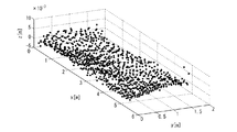
これらの変換式を用いて変換したx軸及びy軸の座標データを図4cに示す。また、z軸を加味した座標データを、三次元データとして図6に示す。例えば、図4cに明らかなように、図の左方向、即ち形状計測装置に近い側は検出点の点密度が高い、所謂密なのに対し、図の右方向、即ち形状計測装置から遠い側は検出点の点密度が低い、所謂粗になっている。例えば前記ガルバノミラーの回転角度θが一定の角度回転する毎に、鋼板までの距離データを検出すると、図7に示すように、レーザ距離計に近い部分では検出点の点密度(図では単位長さあたりのポイント数)が大きく、レーザ距離計から遠くなるほど、検出点の点密度が小さくなる。このデータを全て用いて、回帰曲面解析を行ったのでは、データ数が多すぎて演算負荷やメモリが多大になるばかりでなく、回帰曲面を正しく解析できない恐れがある。即ち、レーザ距離計で得られたデータは、必ずしも検出点を正確に表したものでないこと、鋼板に発生している反りなどの形状は、長手方向に一様であるとは限らず、部分部分で変化している場合があること、などから、密な検出点データを重視して、粗な検出点データが軽んじられてしまう可能性があるためである。 The coordinate data of the x-axis and the y-axis converted using these conversion formulas are shown in FIG. 4c. Further, coordinate data taking the z-axis into account is shown in FIG. 6 as three-dimensional data. For example, as clearly shown in FIG. 4c, the left direction of the figure, that is, the side closer to the shape measuring apparatus has a higher point density of detection points, so-called dense, whereas the right direction of the figure, that is, the side far from the shape measuring apparatus is detected. The dot density is low, so-called rough. For example, when the distance data to the steel plate is detected every time the rotation angle θ of the galvanometer mirror rotates by a certain angle, as shown in FIG. 7, the point density of the detection points (unit length in the figure) is near the laser distance meter. The larger the number of points per unit) and the farther from the laser distance meter, the smaller the point density of the detection points. If the regression surface analysis is performed using all of this data, the number of data is too large and the calculation load and memory become large, and the regression surface may not be analyzed correctly. That is, the data obtained by the laser distance meter does not necessarily represent the detection point accurately, and the shape such as warpage occurring in the steel plate is not always uniform in the longitudinal direction, This is because there is a possibility that coarse detection point data may be disregarded with emphasis on dense detection point data.
そこで、図7に示すように、特に鋼板の長手方向の検出点の点密度が一様になるように前記図3の演算処理のステップS5で間引き処理を行う。間引く量は、形状計測装置、即ちレーザ光の照射装置と検出点との距離に応じて決定する。この距離情報は、鋼板の位置と鋼板寸法から求める方法や、レーザ距離計で予め測定した距離を用いてもよい。例えば、処理を行う鋼板の長手方向をi=1〜n個の区間に等間隔に区分し、この区間の鋼板長手方向長さを単位長さLp、単位長さLp当たりの検出点数を(N)i、処理後の単位長さLp当たりの検出点数をNpとすると、間引き処理を行う間隔(dN)iは下記6式で表れる。 Therefore, as shown in FIG. 7, the thinning process is performed in step S5 of the calculation process of FIG. 3 so that the point density of the detection points in the longitudinal direction of the steel sheet is uniform. The thinning amount is determined according to the distance between the shape measuring device, that is, the laser beam irradiation device and the detection point. As this distance information, a method of obtaining from the position of the steel plate and the size of the steel plate or a distance measured in advance with a laser distance meter may be used. For example, the longitudinal direction of the steel sheet to be processed is equally divided into i = 1 to n sections, the length in the steel sheet longitudinal direction of this section is the unit length Lp, and the number of detection points per unit length Lp is (N ) I , where Np is the number of detection points per unit length Lp after processing, the interval (dN) i for performing the thinning processing is expressed by the following six equations.
例えば、前記鋼板の長手方向の単位長さLpを基準として処理を行う場合、i=1〜nとすると、各区間の間引き処理を行う鋼板の検出点範囲の開始位置(X1)iは下記7式で表れる。 For example, when the processing is performed based on the unit length Lp in the longitudinal direction of the steel sheet, if i = 1 to n, the starting position (X 1 ) i of the detection point range of the steel sheet that performs the thinning process of each section is as follows: Appears in Equation 7.
また、各区間の間引き処理を行う鋼板の検出点範囲の終了位置(X2)iは下記8式で表れる。 Further, the end position (X 2 ) i of the detection point range of the steel sheet that performs the thinning process in each section is expressed by the following eight equations.
従って、単位長さLp当たり、区間毎の検出点数(N)iは下記9式を満たす検出点の総数で表れる。 Therefore, the number of detection points (N) i for each section per unit length Lp is expressed by the total number of detection points that satisfy the following formula (9).
![]()
![]()
例えば、間引き処理後の全検出点数をNpとすると、間引き処理後の区間毎の検出点数(Np)iは下記10式で表れる。 For example, if the total number of detected points after the thinning process is Np, the number of detected points (Np) i for each section after the thinning process is expressed by the following equation (10).
従って、下記11式を満たすように間引き処理を行う間隔(dN)iを区間毎に調整すればよい。 Accordingly, the interval (dN) i for performing the thinning process may be adjusted for each section so as to satisfy the following expression (11).
間引き処理後の単位長さ当たり、区間毎の検出点数の一例を下記表1に、そのヒストグラムを図8に、その結果、間引かれた検出データの三次元マップを図9に示す。下記表1より、間引き処理前に最大約600点あった検出点数差が概ね数十点の差に縮まっていることが分かる。 An example of the number of detection points per unit length after the thinning process is shown in Table 1 below, a histogram thereof is shown in FIG. 8, and as a result, a three-dimensional map of the thinned detection data is shown in FIG. From Table 1 below, it can be seen that the difference in the number of detected points, which was about 600 points before the thinning-out process, is reduced to a difference of several tens of points.
この間引かれて点密度が均一化された検出点データに対して、図3の演算処理のステップS6では、鋼板の表面が或る曲面に近似しているとして回帰曲面解析を行う。回帰曲面の演算方法としては、下記12式を用いた。 In step S6 of the calculation process of FIG. 3, the regression surface analysis is performed on the detection point data in which the point density is uniformed by the thinning, assuming that the surface of the steel plate approximates a certain curved surface. The following 12 equations were used as the regression surface calculation method.
また、式中のfは、内挿曲面fであり、下記13式に示す、データ点を通過するという拘束条件を持つ任意の曲面である。 Further, f in the equation is an interpolated curved surface f, which is an arbitrary curved surface having a constraint condition of passing through a data point shown in the following equation (13).
前記13式の拘束条件を満たす内挿曲面は無限に存在するが、薄板スプライン曲面は、曲率を最小化するという意味で最適な内挿曲面となる。薄板スプライン曲面fの汎関数は下記14式で表れる。
Although there are an infinite number of interpolated curved surfaces that satisfy the constraint conditions of the
この薄板スプライン汎関数に変分原理を適用することで、薄板スプライン曲面を求めることができる。前記14式の薄板スプライン汎関数に変分原理を適用すると、下記15式が得られる。 A thin plate spline curved surface can be obtained by applying a variational principle to the thin plate spline functional. When the variational principle is applied to the thin plate spline functional of the above 14 equations, the following 15 equations are obtained.
前記15式から、薄板スプライン曲面の微分方程式は下記16式で表れる。 From the equation (15), the differential equation of the thin plate spline curved surface is expressed by the following equation (16).
また、薄板スプライン曲面の境界条件は下記17式で与えられる。 The boundary condition of the thin plate spline curved surface is given by the following equation (17).
一般に、前記17式の境界条件の下で、前記16式の微分方程式の解析解を求めることはできないが、もし内挿領域Ωが無限大であるならば、前記16式の微分方程式の解は単純となり、c1、c2、c3を未知パラメータとして下記18式の薄板スプライン曲面が求められる。 In general, the analytical solution of the differential equation of the equation 16 cannot be obtained under the boundary condition of the equation 17, but if the interpolation region Ω is infinite, the solution of the differential equation of the equation 16 is The following 18 thin plate spline curved surfaces are obtained with c 1 , c 2 , and c 3 as unknown parameters.
この18式の薄板スプライン曲面の右辺第4項は、グリーン関数の和である。また、18−1〜18−3式は、拘束条件である。
回帰曲面の未知パラメータは、情報量基準の評価関数より求めた。情報量基準を極小化するパラメータ数が、最適なパラメータ数となる。情報量基準は、種々存在するが、最も単純な物として、赤池情報量基準が知られている。赤池情報量基準の評価関数は、下記19式で与えられる。
The fourth term on the right side of the thin plate spline curved surface of Equation 18 is the sum of the Green functions. Further, equations 18-1 to 18-3 are constraint conditions.
The unknown parameter of the regression surface was obtained from the evaluation function based on the information amount. The number of parameters that minimizes the information amount criterion is the optimum number of parameters. There are various information amount standards, but the Akaike information criterion is known as the simplest. The evaluation function based on the Akaike information amount is given by the following equation (19).
前記18式〜19式を組合せれば、検出点を内挿する回帰曲面を解析することができる。図10は、図9の検出点を用いた回帰曲面解析の演算結果である。同図は、x軸、y軸共に、40分割の矩形メッシュとして表示した。
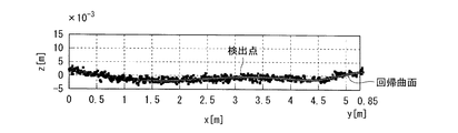
そして、前記図3の演算処理のステップS7では、この解析された回帰曲面を用いて、実際の鋼板の形状を評価すべく同定する。図11は、鋼板の幅方向中央部の幅±50mmの範囲の検出点のz軸方向の高さ分布と、解析された回帰曲面のz軸方向の高さ分布を重ね合わせものである。同図より明らかなように、本実施形態では、鋼板の高さ方向の分布について、最適な回帰曲面を得ることができる。また、図12は、x軸方向、y軸方向共に40分割し、高さ分布をプロットしたものである。同図より、回帰曲面を解析することで、検出点の位置に関わらず、回帰曲面から任意の位置の高さ情報を取出すことも可能となる。
By combining the above 18 to 19 equations, it is possible to analyze a regression surface that interpolates detection points. FIG. 10 shows calculation results of regression surface analysis using the detection points of FIG. In the figure, both the x-axis and the y-axis are displayed as a 40-divided rectangular mesh.
Then, in step S7 of the calculation process of FIG. 3, using the analyzed regression surface, identification is performed to evaluate the actual shape of the steel sheet. FIG. 11 superimposes the height distribution in the z-axis direction of the detection points in the range of the width ± 50 mm in the central portion in the width direction of the steel sheet and the height distribution in the z-axis direction of the analyzed regression surface. As is clear from the figure, in this embodiment, an optimal regression surface can be obtained for the distribution in the height direction of the steel sheet. FIG. 12 is a plot of the height distribution divided into 40 in both the x-axis direction and the y-axis direction. From the figure, by analyzing the regression surface, it is possible to extract height information at an arbitrary position from the regression surface regardless of the position of the detection point.
次に、前記制御装置6内のコンピュータシステムで行われる鋼板Sの形状矯正のための演算処理について、図13のフローチャートを用いて説明する。この演算処理は、例えば鋼板の形状矯正開始指令と同時に行われ、まずステップS11で、例えば前記図11、図12のような曲面関数化を行い、鋼板Sの歪み形状計測を行う。具体的には、前述のように回帰曲面から任意の位置の高さ情報を得ることができるので、鋼板Sの隅部を基準点とし、長さ方向をx軸、幅方向をy軸、高さ方向をz軸(歪み)として歪み形状を得る。
Next, arithmetic processing for correcting the shape of the steel sheet S performed by the computer system in the
次にステップS12に移行して、前記ステップS11で求めた歪み量が形状矯正制御の閾値を超えるか否かを判定し、歪み量が形状矯正制御の閾値を超える場合にはステップS13に移行し、そうでない場合にはメインプログラムに復帰する。
ステップS13では、前記ステップS11で求めた歪み量を2階微分することで鋼板Sの曲率を算出する。
Next, the process proceeds to step S12, where it is determined whether or not the distortion amount obtained in step S11 exceeds the threshold value for shape correction control. If the distortion value exceeds the threshold value for shape correction control, the process proceeds to step S13. Otherwise, return to the main program.
In step S13, the curvature of the steel sheet S is calculated by differentiating the distortion amount obtained in step S11.
次にステップS14に移行して、前記ステップS13で算出された鋼板Sの曲率のうち、プレス機で加圧矯正する一カ所に着目し、その着目箇所の曲率から曲率パターンを抽出する。この曲率パターンの抽出とは、後述する矯正パターンデータベースに存在するパターンと同じ場合には、その曲率パターンをそのまま用い、矯正パターンデータベースに類似するパターンが存在する場合には、その類似パターンを選択する。なお、後述するステップS17から当該ステップS14に移行した場合には、加圧矯正する箇所を変更して、同じように曲率パターンを抽出する。 Next, the process proceeds to step S14, and pays attention to one portion of the curvature of the steel sheet S calculated in step S13 to be pressure-corrected by a press, and a curvature pattern is extracted from the curvature of the portion of interest. When the curvature pattern extraction is the same as a pattern existing in the correction pattern database described later, the curvature pattern is used as it is, and when a similar pattern exists in the correction pattern database, the similar pattern is selected. . In addition, when it transfers to the said step S14 from step S17 mentioned later, the location where pressure correction is carried out is changed, and a curvature pattern is extracted similarly.
次にステップS15に移行して、ステップS13で抽出された曲率パターンと、記憶されている矯正パターンデータベース(図ではDB)を比較して、シム(敷棒)、ラムの位置を決定する。シムは、鋼板と定盤の間に隙間を形成するものである。前述したように、加圧ラムは、シム間の鋼板に曲げモーメントを付与して形状を矯正するものであるから、着目する加圧矯正位置の曲率パターンが決まれば、シムを敷く位置、及び加圧ラムによって加圧する位置が決まる。 Next, the process proceeds to step S15, where the curvature pattern extracted in step S13 is compared with the stored correction pattern database (DB in the figure) to determine the positions of shims (laying bars) and rams. The shim forms a gap between the steel plate and the surface plate. As described above, the pressure ram corrects the shape by applying a bending moment to the steel sheet between the shims. Therefore, if the curvature pattern of the pressure correction position of interest is determined, the position where the shim is laid and The pressurizing position is determined by the pressure ram.
次にステップS16に移行して、鋼板の厚さ、幅、降伏応力などから、シムの厚さ及び加圧ラムによる圧下力(荷重)を決定する。前記ステップS13で算出された加圧矯正位置の曲率は加圧ラムによる曲げモーメントと等価であることから、その曲げモーメントと、断面2次モーメントと呼ばれる鋼板Sの幅、厚さの断面係数、及び縦弾性係数などの材料特性から、付与すべき荷重(圧下力)が得られる。また、鋼板に荷重を付加しても、鋼板にはスプリングバックと呼ばれる弾性回復があるので、このスプリングバック分をシムで付加する。従って、シムの厚さは、スプリングバック量に等しい。 Next, the process proceeds to step S16, where the thickness of the shim and the rolling force (load) by the pressure ram are determined from the thickness, width, yield stress, and the like of the steel plate. Since the curvature of the pressure correction position calculated in step S13 is equivalent to the bending moment by the pressure ram, the bending moment and the section modulus of the width, thickness, and thickness of the steel sheet S called the secondary moment of section, and The load (rolling force) to be applied can be obtained from material properties such as the longitudinal elastic modulus. Even if a load is applied to the steel plate, the steel plate has an elastic recovery called a spring back, and this spring back is added by a shim. Therefore, the thickness of the shim is equal to the amount of springback.
次にステップS17に移行して、ベッド2,3のローラ径や鋼板Sの位置情報から、加圧ラムの直下に加圧矯正位置を移動させるためのローラ駆動量を決定する。即ち、鋼板Sの位置が決まれば加圧矯正位置が何処にあるのかが求められ、その加圧矯正位置を加圧ラムの直下に移動させるための移動量が求められ、その移動量をローラ径で除せばローラの回転量が得られる。
Next, the process proceeds to step S17, and the roller driving amount for moving the pressure correction position directly below the pressure ram is determined from the roller diameters of the
次にステップS18に移行して、ステップS15で決定されたシム、ラム位置、ステップS16で決定されたシム厚、圧下力、ステップS17で決定されたローラ駆動量を夫々実行することにより、プレス矯正を行う。プレス矯正によって、全ての加圧矯正位置が終了した場合にはメインプログラムに復帰し、終了していない場合にはステップS14に移行する。
この演算処理によれば、前記図3の演算処理で求めた回帰曲面を用いて、鋼板Sの歪みを求め、この歪みが加圧矯正されるように、加圧矯正する位置を次々と変えながら、鋼板全体の歪みを加圧矯正することができる。
Next, the process proceeds to step S18, and press correction is performed by executing the shim and ram position determined in step S15, the shim thickness determined in step S16, the rolling force, and the roller driving amount determined in step S17. I do. If all the pressure correction positions are completed by press correction, the process returns to the main program, and if not completed, the process proceeds to step S14.
According to this calculation process, using the regression surface obtained in the calculation process of FIG. 3, the distortion of the steel sheet S is obtained, and the pressure correction position is changed one after another so that the distortion is corrected by pressure. The distortion of the entire steel sheet can be corrected with pressure.
このように本実施形態の鋼板の形状矯正装置によれば、一つのレーザ光源からのレーザ光を偏光し、偏光されたレーザ光を走査して、搬送ライン上に静止した鋼板S上の所定の検出点群を測定し、それらの検出群データからの鋼板の形状を計測し、計測された鋼板の形状計測結果及び検出された鋼板の位置情報に基づいて、プレス機及び搬送ラインを制御することにより、静止した鋼板の形状を容易且つ正確に計測することが可能となり、この正確な鋼板の形状から鋼板の形状を矯正することができると共に、レーザ光源が一つでよいことから構成が簡潔になる。 As described above, according to the shape correction apparatus for a steel plate of the present embodiment, the laser beam from one laser light source is polarized, the polarized laser beam is scanned, and the predetermined plate on the steel plate S stationary on the transport line is obtained. Measure the detection point group, measure the shape of the steel plate from the detection group data, and control the press machine and the conveyance line based on the measured shape measurement result of the steel plate and the position information of the detected steel plate This makes it possible to easily and accurately measure the shape of a stationary steel plate, correct the shape of the steel plate from this accurate shape of the steel plate, and simplify the configuration because only one laser light source is required. Become.
また、レーザ光源を偏光し、偏光されたレーザ光を静止した鋼板上に走査して、静止した鋼板上の所定の検出点群のデータを抽出し、その抽出された鋼板上の検出点群の点密度を均一化する間引き処理を行い、間引き処理された鋼板上の検出点群データから回帰曲面を解析し、解析された回帰曲面から鋼板の形状を計測することにより、静止した鋼板の形状を容易且つ正確に計測することができる。 In addition, the laser light source is polarized, the polarized laser beam is scanned on a stationary steel plate, data of a predetermined detection point group on the stationary steel plate is extracted, and the detection point group on the extracted steel plate is extracted. By performing thinning processing to equalize the point density, analyzing the regression surface from the detected point cloud data on the thinned steel plate, and measuring the shape of the steel plate from the analyzed regression surface, the shape of the stationary steel plate can be obtained. Measurement can be performed easily and accurately.
また、鋼板の諸元及び搬送ラインによる鋼板の搬送状態から、レーザ光の偏光走査範囲を設定することにより、鋼板以外の部分へのレーザ光の照射を低減して、静止した鋼板の形状をより一層容易且つ正確に計測することができる。
なお、前記実施形態では、一枚の鋼板の形状を計測したが、例えば複数枚の鋼板を幅方向に並べ、それらの鋼板の形状を同時に計測することも可能である。そして、その場合、鋼板の幅方向の形状計測長さが長くなり、例えば前記実施形態の場合では、回転台の回転方向の計測点の密度の差が大きくなるので、この方向にも、前述した原理を用いて検出点の間引き処理を行えばよい。
In addition, by setting the laser beam polarization scanning range from the steel plate specifications and the steel plate transport state by the transport line, it is possible to reduce the irradiation of the laser light to parts other than the steel plate, and to make the shape of the stationary steel plate more Measurement can be performed more easily and accurately.
In the embodiment, the shape of a single steel plate is measured. However, for example, a plurality of steel plates can be arranged in the width direction, and the shapes of these steel plates can be measured simultaneously. And in that case, the shape measurement length in the width direction of the steel plate becomes long. For example, in the case of the embodiment, the difference in density of the measurement points in the rotation direction of the turntable becomes large. The detection point thinning process may be performed using the principle.
1 プレス機
2 加圧ラム
3 入側ベッド
4 出側ベッド
5 形状計測装置
6 制御装置
7,8 トラッキング装置
11 レーザ光源
12 回転台
13 ガルバノミラー
DESCRIPTION OF
Claims (2)
Priority Applications (1)
| Application Number | Priority Date | Filing Date | Title |
|---|---|---|---|
| JP2008335469A JP5412829B2 (en) | 2008-12-27 | 2008-12-27 | Steel plate shape straightening device |
Applications Claiming Priority (1)
| Application Number | Priority Date | Filing Date | Title |
|---|---|---|---|
| JP2008335469A JP5412829B2 (en) | 2008-12-27 | 2008-12-27 | Steel plate shape straightening device |
Publications (2)
| Publication Number | Publication Date |
|---|---|
| JP2010155272A JP2010155272A (en) | 2010-07-15 |
| JP5412829B2 true JP5412829B2 (en) | 2014-02-12 |
Family
ID=42573568
Family Applications (1)
| Application Number | Title | Priority Date | Filing Date |
|---|---|---|---|
| JP2008335469A Active JP5412829B2 (en) | 2008-12-27 | 2008-12-27 | Steel plate shape straightening device |
Country Status (1)
| Country | Link |
|---|---|
| JP (1) | JP5412829B2 (en) |
Cited By (1)
| Publication number | Priority date | Publication date | Assignee | Title |
|---|---|---|---|---|
| CN104438464A (en) * | 2014-09-30 | 2015-03-25 | 巢湖广丰金属制品有限公司 | Automatic control system and method for reshaping strip steel surface deformation |
Families Citing this family (13)
| Publication number | Priority date | Publication date | Assignee | Title |
|---|---|---|---|---|
| JP5245817B2 (en) * | 2008-12-27 | 2013-07-24 | Jfeスチール株式会社 | Steel plate shape measuring method and shape measuring device |
| JP5540977B2 (en) * | 2010-08-05 | 2014-07-02 | Jfeスチール株式会社 | Plane shape measurement method |
| JP6086099B2 (en) * | 2014-07-10 | 2017-03-01 | Jfeスチール株式会社 | Surface shape measuring apparatus and method |
| CN104384120A (en) * | 2014-09-30 | 2015-03-04 | 巢湖广丰金属制品有限公司 | Automatic control system and method applied to oxidization layer removing of strip steel |
| CN104289520B (en) * | 2014-09-30 | 2017-05-03 | 巢湖广丰金属制品有限公司 | Strip steel surface deformation shaping equipment |
| CN104368602B (en) * | 2014-09-30 | 2017-04-19 | 巢湖广丰金属制品有限公司 | Automatic control method for shaping strip steel surface defects |
| JP5962820B2 (en) * | 2015-06-11 | 2016-08-03 | 日本軽金属株式会社 | Manufacturing method of liquid cooling jacket |
| JP6376081B2 (en) * | 2015-08-31 | 2018-08-22 | Jfeスチール株式会社 | Method for calculating shape of object, method for correcting press of steel plate, and method for manufacturing steel plate |
| JP6531752B2 (en) * | 2016-12-14 | 2019-06-19 | Jfeスチール株式会社 | Shape evaluation method, steel plate shape correction method, and steel plate manufacturing method |
| KR102233196B1 (en) | 2017-01-31 | 2021-03-26 | 제이에프이 스틸 가부시키가이샤 | Steel shape measurement device and steel shape correction device |
| JP6645526B2 (en) * | 2017-02-24 | 2020-02-14 | Jfeスチール株式会社 | Steel plate shape measuring device and steel plate shape correcting device |
| JP6597696B2 (en) * | 2017-03-29 | 2019-10-30 | Jfeスチール株式会社 | Steel plate shape measuring device and steel plate shape correcting device |
| JP7036093B2 (en) * | 2019-07-22 | 2022-03-15 | Jfeスチール株式会社 | Shape measuring device, shape measuring method, steel plate shape straightening device, steel sheet shape straightening method, steel sheet manufacturing device, and steel sheet manufacturing method |
Family Cites Families (4)
| Publication number | Priority date | Publication date | Assignee | Title |
|---|---|---|---|---|
| JP2506249B2 (en) * | 1991-12-06 | 1996-06-12 | 吉川工業株式会社 | Straightening device |
| JP2813528B2 (en) * | 1993-08-16 | 1998-10-22 | 新日本製鐵株式会社 | Steel plate straightening device |
| JP2000161922A (en) * | 1998-09-22 | 2000-06-16 | Olympus Optical Co Ltd | Height measuring instrument |
| JP4535811B2 (en) * | 2004-09-06 | 2010-09-01 | 株式会社山武 | Data processing method and program |
-
2008
- 2008-12-27 JP JP2008335469A patent/JP5412829B2/en active Active
Cited By (1)
| Publication number | Priority date | Publication date | Assignee | Title |
|---|---|---|---|---|
| CN104438464A (en) * | 2014-09-30 | 2015-03-25 | 巢湖广丰金属制品有限公司 | Automatic control system and method for reshaping strip steel surface deformation |
Also Published As
| Publication number | Publication date |
|---|---|
| JP2010155272A (en) | 2010-07-15 |
Similar Documents
| Publication | Publication Date | Title |
|---|---|---|
| JP5412829B2 (en) | Steel plate shape straightening device | |
| JP5245817B2 (en) | Steel plate shape measuring method and shape measuring device | |
| JP6003583B2 (en) | Shape evaluation method, steel plate shape correction method, and steel plate manufacturing method | |
| CN102135417B (en) | Full-automatic three-dimension characteristic extracting method | |
| JP5676387B2 (en) | Appearance inspection method and apparatus | |
| JP5828817B2 (en) | Shape inspection method for steel bars | |
| Ding et al. | A laser-based machine vision measurement system for laser forming | |
| TW201632870A (en) | System and method for inspecting optical film, apparatus and method for managing quality of optical film | |
| JP5983311B2 (en) | Steel plate shape correction method | |
| JP6624121B2 (en) | Steel plate shape straightening device | |
| CN110116138A (en) | Hot steel plate length and lateral bending measurement method in a kind of operation of rolling | |
| JP4896828B2 (en) | Shape detection method and shape detection apparatus | |
| JP6064871B2 (en) | Thickness measurement method | |
| KR102231141B1 (en) | System for inspecting appearance of rolled plate and method of inspecting appearance of rolled plate using the same | |
| Güldür Erkal et al. | Automated geometric imperfection detection and quantification of CFS members from point clouds | |
| JP5626002B2 (en) | Cropshire drive control method | |
| JP6040215B2 (en) | Inspection method | |
| KR101110848B1 (en) | Method and apparatus for edge position measurement of a curved surface using Laser Vision System | |
| US10619995B2 (en) | Dimension measuring device and method | |
| CN113240629B (en) | Edge-based image matching narrow-gap weld initial point positioning device and method | |
| KR20200008794A (en) | Apparatus and method for analyzing surface defects of steel bar | |
| JP7171535B2 (en) | Surface shape measuring device | |
| US6771363B1 (en) | Device and method for determining a bending angle of a sheet and the use thereof for the angle-bending of sheets | |
| CN115574725B (en) | Steel plate size measurement method and system based on line structured light | |
| Alonso et al. | An Application of Laser Measurement to On-Line Metal Strip Flatness Measurement |
Legal Events
| Date | Code | Title | Description |
|---|---|---|---|
| A621 | Written request for application examination |
Free format text: JAPANESE INTERMEDIATE CODE: A621 Effective date: 20110824 |
|
| A977 | Report on retrieval |
Free format text: JAPANESE INTERMEDIATE CODE: A971007 Effective date: 20130214 |
|
| A131 | Notification of reasons for refusal |
Free format text: JAPANESE INTERMEDIATE CODE: A131 Effective date: 20130219 |
|
| A521 | Request for written amendment filed |
Free format text: JAPANESE INTERMEDIATE CODE: A523 Effective date: 20130410 |
|
| TRDD | Decision of grant or rejection written | ||
| A01 | Written decision to grant a patent or to grant a registration (utility model) |
Free format text: JAPANESE INTERMEDIATE CODE: A01 Effective date: 20131015 |
|
| A61 | First payment of annual fees (during grant procedure) |
Free format text: JAPANESE INTERMEDIATE CODE: A61 Effective date: 20131028 |
|
| R150 | Certificate of patent or registration of utility model |
Ref document number: 5412829 Country of ref document: JP Free format text: JAPANESE INTERMEDIATE CODE: R150 |
|
| R250 | Receipt of annual fees |
Free format text: JAPANESE INTERMEDIATE CODE: R250 |
|
| R250 | Receipt of annual fees |
Free format text: JAPANESE INTERMEDIATE CODE: R250 |
|
| R250 | Receipt of annual fees |
Free format text: JAPANESE INTERMEDIATE CODE: R250 |
|
| R250 | Receipt of annual fees |
Free format text: JAPANESE INTERMEDIATE CODE: R250 |