JP5408552B2 - Image forming apparatus and toner supply method - Google Patents
Image forming apparatus and toner supply method Download PDFInfo
- Publication number
- JP5408552B2 JP5408552B2 JP2010026413A JP2010026413A JP5408552B2 JP 5408552 B2 JP5408552 B2 JP 5408552B2 JP 2010026413 A JP2010026413 A JP 2010026413A JP 2010026413 A JP2010026413 A JP 2010026413A JP 5408552 B2 JP5408552 B2 JP 5408552B2
- Authority
- JP
- Japan
- Prior art keywords
- toner
- image forming
- developing
- forming apparatus
- image
- Prior art date
- Legal status (The legal status is an assumption and is not a legal conclusion. Google has not performed a legal analysis and makes no representation as to the accuracy of the status listed.)
- Expired - Fee Related
Links
Images


Classifications
-
- G—PHYSICS
- G03—PHOTOGRAPHY; CINEMATOGRAPHY; ANALOGOUS TECHNIQUES USING WAVES OTHER THAN OPTICAL WAVES; ELECTROGRAPHY; HOLOGRAPHY
- G03G—ELECTROGRAPHY; ELECTROPHOTOGRAPHY; MAGNETOGRAPHY
- G03G15/00—Apparatus for electrographic processes using a charge pattern
- G03G15/06—Apparatus for electrographic processes using a charge pattern for developing
- G03G15/08—Apparatus for electrographic processes using a charge pattern for developing using a solid developer, e.g. powder developer
- G03G15/0822—Arrangements for preparing, mixing, supplying or dispensing developer
- G03G15/0877—Arrangements for metering and dispensing developer from a developer cartridge into the development unit
-
- G—PHYSICS
- G03—PHOTOGRAPHY; CINEMATOGRAPHY; ANALOGOUS TECHNIQUES USING WAVES OTHER THAN OPTICAL WAVES; ELECTROGRAPHY; HOLOGRAPHY
- G03G—ELECTROGRAPHY; ELECTROPHOTOGRAPHY; MAGNETOGRAPHY
- G03G15/00—Apparatus for electrographic processes using a charge pattern
- G03G15/06—Apparatus for electrographic processes using a charge pattern for developing
- G03G15/08—Apparatus for electrographic processes using a charge pattern for developing using a solid developer, e.g. powder developer
- G03G15/0822—Arrangements for preparing, mixing, supplying or dispensing developer
- G03G15/0848—Arrangements for testing or measuring developer properties or quality, e.g. charge, size, flowability
- G03G15/0856—Detection or control means for the developer level
- G03G15/0862—Detection or control means for the developer level the level being measured by optical means
Landscapes
- Physics & Mathematics (AREA)
- General Physics & Mathematics (AREA)
- Dry Development In Electrophotography (AREA)
- Control Or Security For Electrophotography (AREA)
Description
本発明は、画像形成装置およびトナー供給方法に関するものである。 The present invention relates to an image forming apparatus and a toner supply method.
従来、非磁性または磁性の一成分の現像剤たるトナーをトナー担持体たる現像ローラに担持し、潜像担持体たる感光体と現像ローラとが対向する現像領域で、現像ローラ上のトナーを感光体上の潜像に供給することで現像する一成分現像装置が知られている。 Conventionally, toner that is a non-magnetic or magnetic one-component developer is carried on a developing roller that is a toner carrying member, and the toner on the developing roller is exposed in a developing region where the photosensitive member that is a latent image carrying member and the developing roller face each other. There is known a one-component developing device that develops by supplying a latent image on a body.
上記一成分現像装置においては、現像装置内のトナーが無くなった時点で現像装置が交換されるため、交換時期に達しておらず、継続使用可能な現像ローラまでもが交換され、資源が無駄になってしまうことがあった。また、現像装置内のトナーが無くなる時期と、現像装置内の現像ローラなどの交換時期とが同じとなるよう構成した場合、現像装置に大量のトナーを収容するスペースを確保する必要があり、装置が大型化してしまう。 In the above one-component developing device, since the developing device is replaced when the toner in the developing device runs out, the replacement time is not reached, and even the developing roller that can be used continuously is replaced, and resources are wasted. Sometimes it became. Further, when the time when the toner in the developing device runs out is the same as the time when the developing roller in the developing device is replaced, it is necessary to secure a space for storing a large amount of toner in the developing device. Will become larger.
特許文献1には、トナーを収容するトナー収容器を現像装置とは別に設け、供給手段によりトナー収容器のトナーを現像装置に供給する画像形成装置が記載されている。これにより、現像装置内に供給するトナーが無くなった場合、トナー収容器のみを交換すればよいので、継続使用可能な現像ローラまでもが交換されることがなくなる。また、トナー収容器に収容する新規トナー量は、現像装置内の現像ローラの交換時期を考慮しなくてもよいため、トナー収容器の容量を小さくでき、装置の大型化を抑制することができる。
また、上記特許文献1の画像形成装置では、現像装置内のトナー量が、下限値未満となったら、供給手段によりトナー収容器のトナーを現像装置に供給している。このため、トナー供給後の現像装置内には、供給された新規トナーと、現像に用いられずに長期にわたり現像装置内に残留している古いトナーとが混在する。
In the image forming apparatus disclosed in
特許文献2には、現像装置内に残留している劣化した古いトナーがあるところに新規トナーを供給したことによって生じる地汚れを抑制するために、次のような構成の画像形成装置が記載されている。すなわち、現像装置内のトナー量が、下限値未満となったら、現像装置へのトナー供給に先立って、現像装置に残留しているトナーを像担持体へ向けて吐き出させるよう制御するという画像形成装置である。これにより、現像装置に残留していた古いトナーが像担持体に吐き出され、現像装置内がほとんど空になった状態で、トナー収容器から新規トナーが供給される。よって、新規トナーが供給された後の現像装置内は、ほとんどが新規トナーになるので、新規トナー供給後の地汚れを抑制することができる。 Patent Document 2 describes an image forming apparatus having the following configuration in order to suppress scumming caused by supplying new toner where there is deteriorated old toner remaining in the developing device. ing. That is, when the amount of toner in the developing device becomes less than the lower limit value, image formation is controlled such that the toner remaining in the developing device is discharged toward the image carrier prior to supplying the toner to the developing device. Device. Thus, the old toner remaining in the developing device is discharged to the image carrier, and new toner is supplied from the toner container in a state where the developing device is almost empty. Therefore, since most of the developing device after the new toner is supplied becomes new toner, it is possible to suppress the background stain after the new toner is supplied.
ここで、劣化した古いトナーと新規トナーとを混合させると、地汚れが生じる理由について、具体的に説明する。
現像装置内に残留する古いトナーは、長期にわたり攪拌などによるストレスを受け、トナー粒子表面に外添されている流動性及び帯電性を調整するための外添剤が離脱したり粒子中に埋没したりして、トナーの正規帯電極性である例えば負極性に摩擦帯電しにくい。一方、現像装置内に供給された新規トナーは、劣化しておらず負極性に摩擦帯電しやすい。このため、負極性に帯電しやすい新規トナーと、劣化して負極性に帯電しにくい古いトナーとが摺擦すると、荷電分離が起こり、古いトナーの電子が、新規トナーへ移動する。その結果、新規トナーの負極性の帯電量が増加し、古いトナーの帯電量が減少したり、正極性に帯電したりしてしまう。その結果、現像装置内のトナー帯電分布が、ブロードになるとともに、負極性に帯電量が大きなところと、帯電量が0付近のところとに2つのピークをもつような分布となる。このように、新規トナー供給後、劣化した古いトナーが、弱帯電トナーとなったり、逆帯電トナーとなったりするので、新規トナー供給後の画像形成において、像担持体たる感光体のトナーを載せたくない部分(非潜像部分)に上記劣化した古いトナーが付着してしまう。その結果、地汚れが新規トナー供給前に比べて悪くなってしまう。
Here, the reason why background smear occurs when old deteriorated toner and new toner are mixed will be described in detail.
The old toner remaining in the developing device is subjected to stress due to agitation for a long time, and the external additive for adjusting the fluidity and chargeability externally added to the toner particle surface is detached or buried in the particle. In other words, it is difficult to frictionally charge to the normal charging polarity of the toner, for example, to the negative polarity. On the other hand, the new toner supplied into the developing device is not deteriorated and is easily triboelectrically charged to the negative polarity. For this reason, when a new toner that is easily charged to a negative polarity and an old toner that is deteriorated and hardly charged to a negative polarity are rubbed, charge separation occurs, and electrons of the old toner move to the new toner. As a result, the negative charge amount of the new toner increases, the charge amount of the old toner decreases, or the positive toner is charged positively. As a result, the toner charge distribution in the developing device becomes broad, and has a distribution having two peaks at a negative charge amount where the charge amount is large and a charge amount near zero. Thus, after the new toner is supplied, the deteriorated old toner becomes weakly charged toner or reversely charged toner. Therefore, in the image formation after the new toner is supplied, the toner of the photoconductor as the image carrier is placed. The deteriorated old toner adheres to a portion (non-latent image portion) that is not desired. As a result, the background dirt becomes worse than before the supply of new toner.
しかし、例えば、現像装置内の単位時間当りのトナーの消費量が早く、短期間で現像装置内の残留トナーが所定値以下となったときなどは、現像装置内のトナーにさほどストレスがかかっておらず、現像装置内に残留している古いトナーの劣化が軽微な場合がある。現像装置内に残留している古いトナーの劣化が軽微な場合、十分な帯電能力を有しているため、新規トナーを供給して、新規トナーと摺擦しても、荷電分離が起こることがほとんどない。このため、古いトナーの劣化が軽微な場合、新規トナー供給後の現像装置内のトナー帯電分布は、負極性の所定の帯電量をピークにもつシャープな分布を維持することができる。その結果、新規トナー供給後も地汚れが抑制された画像を得ることができる。 However, for example, when the toner consumption per unit time in the developing device is fast and the residual toner in the developing device falls below a predetermined value in a short period of time, the toner in the developing device is stressed so much. In some cases, the deterioration of the old toner remaining in the developing device is slight. If the old toner remaining in the developing device is slightly deteriorated, it has sufficient charging ability, so that even if new toner is supplied and rubbed against the new toner, charge separation may occur. rare. Therefore, when the deterioration of the old toner is slight, the toner charge distribution in the developing device after the new toner is supplied can maintain a sharp distribution having a predetermined negative charge amount as a peak. As a result, it is possible to obtain an image in which scumming is suppressed even after new toner is supplied.
しかし、上記特許文献2においては、現像装置内に残留する古いトナーの劣化が軽微で、十分な帯電能力を有していても、現像装置から像担持体へ吐き出され、破棄されてしまう。その結果、トナーの無駄が生じてしまうという問題があった。 However, in Patent Document 2, the deterioration of the old toner remaining in the developing device is slight, and even if it has sufficient charging ability, it is discharged from the developing device to the image carrier and discarded. As a result, there is a problem that toner is wasted.
本発明は以上の問題点に鑑みなされたものであり、その目的は、新規トナー供給後の地汚れを抑制し、かつ、現像剤の無駄の発生を抑制することができる画像形成装置およびトナー供給方法を提供することである。 SUMMARY OF THE INVENTION The present invention has been made in view of the above problems, and an object of the present invention is to provide an image forming apparatus and a toner supply capable of suppressing scumming after supply of new toner and suppressing waste of developer. Is to provide a method.
上記目的を達成するために、請求項1の発明は、潜像を担持する潜像担持体と、上記潜像担持体表面を帯電させる帯電手段と、上記潜像担持体に潜像を書き込む潜像書込手段と、トナーによって上記潜像担持体上の潜像を現像してトナー像を得る現像手段と、表面を無端移動させる表面無端移動体あるいはこれの表面に保持される記録部材に潜像担持体上のトナー像を転写する転写手段と、上記現像手段に供給するためのトナーを収容するトナー収容器と、上記現像手段内のトナー残量を検知する残量検知手段と、上記残量検知手段が上記現像手段内のトナー量が所定値以下であること検知したら、トナー収容器内のトナーを上記現像手段へ供給するトナー供給手段とを備えた画像形成装置において、画像の地汚れを検知する地汚れ検知手段と、上記残量検知手段が現像手段内のトナー量が所定値以下であること検知したら、地汚れ検知用画像を形成し、上記地汚れ検知手段により地汚れ検知用画像を検知し、上記地汚れ検知手段の地汚れ検知用画像の検知結果に基づいて、トナー供給手段による現像手段へのトナー供給に先立って、現像手段内に残留しているトナーを上記潜像担持体へ向けて吐き出させるトナー吐き出し処理を実行するか否かを判断する判断手段とを備えたことを特徴とするものである。
また、請求項2の発明は、請求項1の画像形成装置において、上記地汚れ検知手段が、所定値を越える地汚れを検知した場合は、トナー吐き出し処理を実行することを特徴とするものである。
また、請求項3の発明は、請求項1または2の画像形成装置において、上記地汚れ検知手段は、上記潜像担持体または上記表面無端移動体の画像形成領域に対向配置され、表面を光学的に検知する第1光学検知手段と、上記潜像担持体または上記の表面無端移動体の非画像形成領域に対向配置され、表面を光学的に検知する第2光学検知手段とを備え、上記地汚れ検知手段は、上記第1光学検知手段の地汚れ検知用画像の検知結果と、上記第2光学検知手段の非画像形成領域の検知結果とに基づいて、地汚れ検知用画像の地汚れを検知することを特徴とするものである。
また、請求項4の発明は、請求項1または2の画像形成装置において、上記表面無端移動体を上記潜像担持体に対して接離させる接離手段を有し、上記地汚れ検知手段は、上記表面無端移動体の画像形成領域に対向配置され、上記地汚れ検知手段は、地汚れ検知用画像の検知結果と、上記表面無端移動体を上記潜像担持体に対して離間させ、離間後の表面移動体を検知したときの検知結果とに基づいて、地汚れ検知用画像の地汚れを検知することを特徴とするものである。
また、請求項5の発明は、請求項1乃至4いずれかの画像形成装置において、上記現像手段は、上記潜像担持体と対向し、トナーを担持するトナー担持体と、トナー担持体の外周面に当接するトナー供給部材と、トナーが上記トナー供給部材から上記トナー担持体側に移動するような電位差を上記トナー担持体の外周面との間に形成するための電圧をトナー供給部材に印加する電圧印加手段とを備え、トナー吐き出し処理時における上記トナー供給部材と上記トナー担持体との間の電位差を、現像動作時における電位差よりも大きくなるよう、上記電圧印加手段を制御することを特徴とするものである。
また、請求項6の発明は、請求項1乃至5いずれかの画像形成装置において、上記表面無端移動体を上記潜像担持体に対して接離させる接離手段を有し、上記トナー吐き出し処理実行時は、上記表面無端移動体を上記潜像担持体から離間させたことを特徴とするものである。
また、請求項7の発明は、請求項1乃至6いずれかの画像形成装置において、上記転写手段による転写工程を経た後の潜像担持体表面に付着している転写残トナーを除去する転写残トナー除去手段を備え、上記トナー収容器に上記トナー除去手段により除去された除去トナーを収容する除去トナー収容部を設けたことを特徴とするものである。
また、請求項8の発明は、請求項1乃至7いずれかの画像形成装置において、上記トナー吐き出し処理を実行してからの上記現像手段の駆動時間に基づいて、上記吐き出し処理を終了することを特徴とするものである。
また、請求項9の発明は、請求項1乃至8いずれかの画像形成装置において、上記トナー吐き出し処理実行時は、上記帯電手段による上記潜像担持体表面の帯電処理を行わないことを特徴とするものである。
また、請求項10の発明は、請求項1乃至9いずれかの画像形成装置において、上記残量検知手段は、現像装置内に収容されているトナーの嵩高さを検知する嵩高さ検知手段を備え、上記嵩高さ検知手段がトナーの嵩高さが所定値以下になったことを検知した後、出力画像のドット数をカウントして、カウント数が所定以上となったら、現像手段内のトナー量が所定値以下であると検知することを特徴とするものである。
また、請求項11の発明は、請求項1乃至10いずれかの画像形成装置において、少なくとも上記潜像担持体と、上記帯電手段と、上記現像手段と一体的に支持して装置本体から着脱可能に構成されたプロセスカートリッジを備えたことを特徴とするものである。
また、請求項12の発明は、潜像担持体上に形成された潜像にトナーを付着させて、上記潜像を現像する現像手段にトナー収容器からトナーを供給するトナー供給方法において、上記現像手段内のトナー量が所定値以下であるか否かを検知するステップと、上記現像手段内のトナー量が所定値以下である場合、地汚れ検知用画像を形成して、地汚れを検知するステップと、検知した地汚れに基づいては、現像手段にトナー収容器からトナー供給する前に、現像手段内に残留しているトナーを上記潜像担持体へ向けて吐き出させるトナー吐き出し処理を実行するか否かを判断するステップとを有することを特徴とするものである。
In order to achieve the above object, a first aspect of the present invention provides a latent image carrier for carrying a latent image, a charging means for charging the surface of the latent image carrier, and a latent image for writing the latent image on the latent image carrier. An image writing unit, a developing unit that develops a latent image on the latent image carrier with toner to obtain a toner image, a surface endless moving body that moves the surface endlessly, or a recording member that is held on the surface A transfer unit that transfers a toner image on the image carrier, a toner container that stores toner to be supplied to the developing unit, a remaining amount detecting unit that detects a remaining amount of toner in the developing unit, and the remaining unit. When the amount detection means detects that the amount of toner in the developing means is less than or equal to a predetermined value, in an image forming apparatus comprising a toner supply means for supplying toner in the toner container to the developing means, Dirt detection means to detect When the remaining amount detecting means detects that the amount of toner in the developing means is less than or equal to a predetermined value, a background detection image is formed, the background detection image is detected by the background detection means, and the background contamination is detected. Toner that discharges the toner remaining in the developing means toward the latent image carrier prior to the toner supply to the developing means by the toner supplying means based on the detection result of the image for detecting soiling by the detecting means And a judging means for judging whether or not to execute the discharge process.
According to a second aspect of the present invention, in the image forming apparatus according to the first aspect, when the scumming detection means detects a scumming exceeding a predetermined value, a toner discharging process is executed. is there.
According to a third aspect of the present invention, in the image forming apparatus according to the first or second aspect, the scumming detecting means is disposed opposite to the image forming region of the latent image carrier or the surface endless moving body, and the surface is optically arranged. A first optical detecting means for detecting the surface and a second optical detecting means arranged to face the non-image forming area of the latent image carrier or the surface endless moving body and optically detect the surface, The scumming detection means is scumming of the scumming detection image based on the detection result of the scumming detection image of the first optical detection means and the detection result of the non-image forming area of the second optical detection means. Is detected.
According to a fourth aspect of the present invention, there is provided the image forming apparatus according to the first or second aspect, further comprising contacting / separating means for contacting and separating the surface endless moving body with respect to the latent image carrier. And the ground contamination detection means separates the detection result of the contamination detection image from the surface endless moving body with respect to the latent image carrier, and is separated from the latent image carrier. Based on the detection result when the subsequent surface moving body is detected, the background contamination of the background detection image is detected.
According to a fifth aspect of the present invention, in the image forming apparatus according to any one of the first to fourth aspects, the developing means faces the latent image carrier, and carries a toner carrier that carries toner, and an outer periphery of the toner carrier. A voltage is applied to the toner supply member that forms a potential difference between the toner supply member that contacts the surface and the outer peripheral surface of the toner support so that the toner moves from the toner supply member toward the toner support. And a voltage application unit, wherein the voltage application unit is controlled so that a potential difference between the toner supply member and the toner carrier during the toner discharge process is larger than a potential difference during the developing operation. To do.
The invention according to claim 6 is the image forming apparatus according to any one of
The invention according to claim 7 is the image forming apparatus according to any one of
According to an eighth aspect of the present invention, in the image forming apparatus according to any one of the first to seventh aspects, the discharge process is terminated based on a driving time of the developing unit after the toner discharge process is executed. It is a feature.
According to a ninth aspect of the present invention, in the image forming apparatus according to any one of the first to eighth aspects, the surface of the latent image carrier is not charged by the charging unit when the toner discharge process is executed. To do.
According to a tenth aspect of the present invention, in the image forming apparatus according to any one of the first to ninth aspects, the remaining amount detecting means includes a bulkiness detecting means for detecting the bulkiness of the toner accommodated in the developing device. Then, after the bulkiness detecting means detects that the bulkiness of the toner has become a predetermined value or less, the number of dots in the output image is counted, and when the count number exceeds the predetermined value, the amount of toner in the developing means is increased. It is detected that it is below a predetermined value.
The invention according to claim 11 is the image forming apparatus according to any one of
According to a twelfth aspect of the present invention, in the toner supply method, the toner is attached to the latent image formed on the latent image carrier, and the toner is supplied from a toner container to the developing means for developing the latent image. A step of detecting whether or not the toner amount in the developing means is less than a predetermined value, and if the toner amount in the developing means is less than or equal to a predetermined value, an image for detecting soiling is formed and the soiling is detected. And a toner discharge process for discharging the toner remaining in the developing unit toward the latent image carrier before supplying the toner from the toner container to the developing unit based on the detected background contamination. And a step of determining whether to execute or not.
本発明によれば、次のようにして、地汚れ検知手段の検知結果に基づいて、トナー吐き出し処理を行うか否かを判断すれば、新規トナー供給後の地汚れを抑制し、かつ、現像剤の無駄の発生を抑制することができる。すなわち、地汚れ検知手段の検知の結果、地汚れが所定値以上の場合は、トナー吐き出し処理を実行してから、現像手段にトナーを供給し、地汚れ検知手段の検知の結果、地汚れが所定値未満の場合は、吐き出し処理を行わずに現像手段にトナーを供給するのである。現像手段内に残留した古いトナーの劣化が進んでいる場合は、十分に摩擦帯電しないため、地汚れが所定値以上となる。よって、地汚れが所定値以上の場合は、トナー吐き出し処理を実行して、現像手段に残留していた古いトナーを吐き出させ、現像手段内がほとんど空になった状態で、新規トナーを供給する。これにより、新規トナー供給後の地肌汚れを抑制することができる。
一方、現像手段内に残留した古いトナーの劣化が軽微であり、十分な摩擦帯電能力を有している場合は、地汚れは所定値未満となる。よって、この場合は、吐き出し処理を行わずに現像手段にトナーを供給する。これにより、トナーの無駄な消費を抑えることができ、かつ、新規トナー供給後の地肌汚れを抑制することができる。
According to the present invention, if it is determined whether or not to perform the toner discharge process based on the detection result of the background contamination detection unit as described below, the background contamination after new toner supply is suppressed and development is performed. The generation of waste of the agent can be suppressed. That is, as a result of detection by the scumming detection means, if scumming is greater than or equal to a predetermined value, the toner discharge process is executed and then toner is supplied to the developing means. If it is less than the predetermined value, the toner is supplied to the developing means without performing the discharge process. When the old toner remaining in the developing unit is deteriorated, the toner is not sufficiently frictionally charged, and the background contamination becomes a predetermined value or more. Therefore, when the background contamination is equal to or greater than the predetermined value, the toner discharging process is executed to discharge the old toner remaining in the developing unit, and new toner is supplied in a state where the developing unit is almost empty. . As a result, background stains after the new toner is supplied can be suppressed.
On the other hand, when the old toner remaining in the developing means is slightly deteriorated and has sufficient frictional charging ability, the scumming is less than a predetermined value. Therefore, in this case, the toner is supplied to the developing unit without performing the discharge process. As a result, wasteful consumption of toner can be suppressed, and background contamination after the supply of new toner can be suppressed.
以下、本発明を適用した画像形成装置として、電子写真方式のプリンタ(以下、単にプリンタという)の一実施形態について説明する。
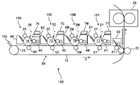
まず、本プリンタの基本的な構成について説明する。図1は、本プリンタを示す概略構成図である。同図において、このプリンタは、イエロー、マゼンタ、シアン、ブラック(以下、Y、M、C、Kと記す)のトナー像を形成するための4つのプロセスカートリッジ10Y,M,C,Kを備えている。これらは、互いに異なる色のY,M,C,Kトナーを用いるが、それ以外は同様の構成になっており、寿命到達時に交換される。Kトナー像を形成するためのプロセスカートリッジ10Kを例にすると、図2に示すように、潜像担持体たるドラム状の感光体1K、帯電装置2K、現像装置4K、転写残トナー除去手段たるドラムクリーニング装置6Kなどを備えている。プロセスカートリッジ10Kは、プリンタ本体に脱着可能であり、一度に消耗部品を交換できるようになっている。
Hereinafter, as an image forming apparatus to which the present invention is applied, an embodiment of an electrophotographic printer (hereinafter simply referred to as a printer) will be described.
First, the basic configuration of the printer will be described. FIG. 1 is a schematic configuration diagram showing the printer. In the figure, this printer includes four
帯電手段たる帯電装置2Kは、感光体1K表面に接触させて連れ回り回転する帯電ローラの芯金の高電圧を印加し、感光体表面を一様に帯電する接触方式の帯電装置であるが、チャージワイヤーに高電圧を印加することにより放電するコロトロン、スコロトロン方式、この他に帯電ブラシ、帯電シート、針電極などを使用することができる。これらは、感光体1Kに対して非接触で感光体表面を帯電できるため、クリーニング性の影響を受けにくいというメリットはあるが、放電に伴って生成されるオゾンやNOx等の放電生成物の発生量が帯電ロール方式に比較し格段に大きいため、感光体の耐久性の面で課題がある。
The
上記現像装置4Kは、一成分現像装置であり、トナー担持体たる現像ローラ41K、現像ローラ41Kにトナーを供給するトナー供給部材たるトナー供給ローラ42Kを備えている。現像装置4Kの上方にはトナー収容器7Kが配置されている。トナー収容器7Kには、新規トナーを貯留しているトナー貯留部71Kと、トナー貯留部71Kの上方に配置され、廃トナーを収容する廃トナー収容部72Kとを備えている。トナー貯留部71K内には、図示しない駆動手段によって回転駆動されるアジテータ71aK、スクリュあるいはコイルなどからなり、現像装置4Kとトナー貯留部71Kとの連結部としての不図示の供給口に向かってトナー貯留部内の新規トナーを搬送する搬送部材71bKが設けられている。搬送部材71bKは、不図示の駆動手段により回転駆動される。アジテータ71aKは、トナー貯留部71K内の新規トナーの流動性を保つために常に回転駆動させ、トナー貯留部内の新規トナーを常に攪拌しておくことが好ましい。
The developing
現像装置4K内には、トナー供給口から供給されたトナー貯留部71Kの新規トナーを現像装置4K内の軸方向全域に移送するためのスクリュなどで構成されたトナー輸送部材44K、装置内のトナーを攪拌するアジテータ43K、トナー担持体である現像ローラ41Kを備えている。また、現像ローラ41Kの表面に先端を当接させ、現像ローラ41Kに担持体されたトナー層を薄層化する薄層化ブレード45K、現像ローラ41Kと当接し、現像ローラ41Kにトナーを供給するトナー供給ローラ42Kなども備えている。
In the developing
トナー供給ローラ42Kは、現像ローラ41Kに当接し、現像ローラ41Kと共回り回転、または、現像ローラ41Kの進行方向と逆方向(カウンター方向)に回転して、トナー供給ローラ42Kに付着したトナーを現像ローラ41Kへ供給している。トナー供給ローラ42Kは、表面には空孔(セル)を有した構造の発泡材料が被覆されており、現像装置4K内のトナーを効率よく付着させて取り込むと共に、現像ローラ41Kとの当接部での圧力集中によるトナー劣化を防止している。トナー供給ローラ42Kには、電圧印加手段たる不図示の電源からトナーの正規帯電極性(負極性)の電圧が印加されている。この電圧は、現像ローラ41Kに印加されている電圧(負極性電圧)よりも低い負極性電圧、すなわち、現像ローラ41Kに印加されている電圧よりも絶対値が大きい負極性電圧である。これにより、現像ローラ41Kとの当接部では、電界が形成される。現像装置内のトナーは、アジテータ43Kによって攪拌されながら摩擦帯電が促され、正規帯電極性(負極性)に帯電しているので、トナー供給ローラ42K保持され当接部へ搬送されたトナーは、上記電界の影響によりトナー供給ローラ42Kから現像ローラ41Kへ向かって移動し、現像ローラ41Kに静電的に付着する。現像ローラ41Kに付着したKトナーは、現像ローラ41Kの回転に伴ってローラと薄層化ブレード45Kとの当接位置を通過する際に、ローラ表面上での層厚が規制される。そして、層厚規制後のKトナーは、現像ローラ41Kと感光体1Kとの当接部である現像領域において、感光体1K表面のK用の静電潜像に付着する。この付着により、K用の静電潜像がKトナー像に現像される。
The
図3は、プロセスカートリッジ10Kが備え、図2では記載されていない廃トナー回収ベルト63Kと、プロセスカートリッジ10Kの他の部材との位置関係を示した説明図である。
プロセスカートリッジ10Kの端部には、ドラムクリーニング装置6Kから、トナー収容器7Kの廃トナー収容部72Kへ延びる廃トナー搬送部64Kが設けられている。この廃トナー搬送部64Kの下端は、ドラムクリーニング装置6Kと連通しており、廃トナー搬送部64Kの上端は、トナー収容器7Kの廃トナー収容部72Kと連通している。廃トナー搬送部64K内には、無端状の廃トナー回収ベルト63Kが設けられており、廃トナー回収ベルト62Kは、従動ローラ65Kと駆動ローラ66Kとに張架されている。廃トナー回収ベルト63Kの外周面には、所定の間隔を開けて突状部63aKが形成されている。廃トナー回収ベルト63Kの突状部63aKは、ベルト幅と同一の幅を有しており、その頂面が、廃トナー搬送部64Kのベルト対向面と隙間なく接触するような高さを有している。
FIG. 3 is an explanatory diagram showing the positional relationship between the waste
At the end of the
感光体1Kからドラムクリーニング装置6Kによって除去されたトナーは、廃トナーとして廃トナー搬送部材62Kによってプロセスカートリッジ10Kの端部の廃トナー搬送部64Kの下端へ搬送される。廃トナー搬送部64Kの下端に搬送された廃トナーは、廃トナー回収ベルト63Kの突状部63aKによって掻き取られる。突状部63aKによって掻き取られた廃トナーは、図3に示すように、突状部63aKと廃トナー搬送部64Kの底面との空間Sに保持されて、上方(図中矢印B方向)へ搬送される。廃トナー回収ベルト63Kによって、廃トナー搬送部64Kの上部にまで廃トナーが搬送されると、廃トナーが、不図示の廃トナー回収経路へ落下する。トナー回収経路へ落下した廃トナーは、廃トナー回収スクリュ73K(図2参照)によって廃トナー収容部72Kへ搬送される。廃トナー収容部72Kに回収された廃トナーは、再び現像するトナーとして使用しないで廃トナー収容部72Kに溜め込んだままとなる構成となっている。
The toner removed from the
トナー収容器7Kは、装置本体に対して着脱可能に設けられており、トナー貯留部71K内の新規トナーが無くなると、装置本体から取り外され、新規トナーが収容された別のトナー収容器7Kと交換される。このとき、トナー収容器7Kの廃トナー収容部72Kに溜まった廃トナーが、同時に回収される。
The
また、現像装置4Kには、ケースから突出し、透明な材質で構成される検知窓46Kを有している。
図4は、現像装置4Kの平面図であり、図に示すように、嵩高さ検知手段である透過型光センサ81Kの受光部81aKと、発光部81bKとが、検知窓46Kを挟んで対向配置されている。検知窓46Kは、中空部を有しており、この中空部は、現像装置4K内部と連通している。現像装置4K内のトナーの嵩高さが、検知窓46Kよりも高い位置にある場合は、この検知窓46Kの中空部にトナーが満たされており、透過型光センサ81Kの発光部81bKからの光が、遮られている。このため、受光部81aKでは、光を検知せず、受光部81aKからの出力値は、ほぼゼロである。現像装置4K内のトナーが消費されて、現像装置4K内のトナー嵩高さが減少し、トナー嵩高さが、検知窓46Kの位置よりも低くなると、検知窓46Kの中空部にトナーが無くなり、発光部81bKの光が受光部81aKにより受光される。その結果、受光部81aKから所定の値の出力値が得られ、現像装置4K内のトナー嵩高さが、所定値以下となったことが検知される。そして、不図示の制御部は、この透過型光センサ81Kからの出力値に基づいて、現像装置4K内のトナー残量を検知する。すなわち、本実施形態では、嵩高さ検知手段たる透過型光センサ81Kと、不図示の制御部とで、現像装置4K内のトナー残量を検知する残量検知手段を構成している。本実施形態では、透過型光センサ81Kで、現像装置4K内のトナー嵩高さに基づいて、現像装置4K内のトナー残量を検知しているが、現像装置4K内に圧電センサなどを設けて、現像装置4K内のトナー残量をダイレクトに検知しても構わない。
Further, the developing
FIG. 4 is a plan view of the developing
不図示の制御部は、現像装置内のトナー残量が所定値未満となったら、先の図2で示した搬送部材71bKを回転駆動させて、トナー貯留部71Kから現像装置4K内へ新規トナーを供給する。すなわち、不図示の制御部と、搬送部材71bKとで、トナー供給手段を構成している。また、装置の温湿度環境により、トナー流動性が変動する。このため、搬送部材71bKを常に一定時間駆動させた場合、装置の環境により現像装置4K内に供給する新規トナー量がばらついてしまう。このため、不図示の温湿度センサの検知結果に基づき、搬送部材71bKの駆動時間を変化させるのが好ましい。
When the remaining amount of toner in the developing device becomes less than a predetermined value, the control unit (not shown) rotates the conveying member 71bK shown in FIG. 2 to generate new toner from the
上記ドラムクリーニング装置6Kは、先端が感光体表面に当接した弾性体から構成されるクリーニングブレード61Kと、クリーニングブレード61Kによって除去された廃トナーを上記した廃トナー搬送部64Kへ搬送するための廃トナー搬送部材62Kなどを備えている。
The
図2〜4を用いてK用のプロセスカートリッジ10Kについて説明したが、他色用のプロセスカートリッジ10Y,M,CはK用のプロセスカートリッジ10Kと同様の構成になっており、同様のプロセスにより、感光体1Y,M,C表面にY,M,Cトナー像が形成されるので説明を省略する。
Although the
先の図1に示すように、プロセスカートリッジ10Y,M,C,Kの鉛直方向下方には、無端移動体である中間転写ベルト15を備えた転写手段たる転写ユニット30が配設されている。中間転写ベルト15は、テンションローラ23、駆動兼二次転写対向ローラ21によって張架されており、駆動兼二次転写対向ローラ21の延長方向に取り付けられた駆動モーターによって図中矢印C方向に回転する。転写ユニット30は、中間転写ベルト15の他に、4つの一次転写ローラとしての一次転写ローラ5Y,M,C,K、ベルトクリーニング装置33などを備えている。この転写ユニット30は、プリンタ100本体に対して着脱可能に構成されており、一度に消耗部品を交換できるようになっている。
As shown in FIG. 1, a
このような構成において、画像形成がネガポジ方式(露光部電位の絶対値を未露光部電位の絶対値よりも低くしトナーを付着させる)で行われる場合、各帯電装置2Y,M,C,Kによって各感光体1Y,M,C,Kの表面が一様に負極性に帯電される。次に、感光体1Y,M,C,Kの鉛直方向上方に配置された潜像形成手段としての図示しない露光装置から、各感光体1Y,M,C,Kに対して画像情報に応じた光3Y,M,C,Kが照射され、各感光体1Y,M,C,K上にそれぞれの色ごとの静電潜像が形成される。この露光装置としては、レーザーダイオードを用いたレーザービームスキャナなどを用いることができる。次に、各現像装置4Y,M,C,Kの現像ローラ41Y,M,C,Kに、図示しない電源から負極性で、感光体1Y,M,C,K上の非露光部電位よりも絶対値の大きい現像バイアスを印加することにより、その現像ローラ41Y,M,C,K上に担持されたトナーを感光体1Y,M,C,K上の静電潜像に移動させ、その静電潜像にトナーを付着させる。これにより、感光体1Y,M,C,K上に静電潜像に対応したトナー像が形成される。
In such a configuration, when image formation is performed by a negative positive method (the absolute value of the exposed portion potential is made lower than the absolute value of the unexposed portion potential to attach the toner), each charging device 2Y, M, C, K As a result, the surfaces of the
上記現像装置4Y,M,C,Kによってそれぞれ現像された各感光体1Y,M,C,K上の各色トナー像は、中間転写体たる中間転写ベルト15上に互いに重なり合うように一次転写される。中間転写ベルト15に転写されず各感光体1Y,M,C,Kに残った転写残トナーは、各ドラムクリーニング装置6Y,M,C,Kのクリーニングブレード61Y,M,C,K上により感光体表面から除去される。
The color toner images on the
また、プリンタは、中間転写ベルト15の鉛直方向下方に図示しない給紙カセットが配置されている。給紙カセットから給送された転写紙は、図示しない搬送ガイドによってガイドされながら搬送ローラで搬送され、不図示のレジストローラが設けられている一時停止位置に送られる。転写紙は、レジストローラにより所定のタイミングで中間転写ベルト15の二次転写対向ローラ21に巻き付いた部分と二次転写ローラ22との間の二次転写部に供給される。そして、二次転写ローラ22に図示しない電源により所定の二次転写バイアスを印加させることで中間転写ベルト15上に形成されたカラー画像が、転写紙上に二次転写され、転写紙上にカラー画像が形成される。このカラー画像が形成された転写紙は、定着ユニット26でトナー像が定着された後、不図示の排紙トレイ上に排出される。また、二次転写後の中間転写ベルト15に残った転写残トナーが、ベルトクリーニング装置33により除去される。ベルトクリーニング装置33で除去された転写残トナーは、廃トナーとして、不図示の搬送手段により、ベルトクリーニング装置33から、トナー収容器7Y内の廃トナー収容部72Yへ搬送される。
In the printer, a sheet feeding cassette (not shown) is arranged below the
また、プリンタ100は、中間転写ベルト15を感光体1Y,M,Cに対して接離させる接離手段たる接離機構50を有している。
図5は、接離機構50の概略構成図である。
図5に示すように、接離機構50は、Y,M,Cの一次転写ローラ5Y,M,Cを支持し、その一端側が、回転軸52により揺動可能に支持された揺動部材51を有している。揺動部材51の他端は、ソレノイド53によって支持されており、ソレノイド53の駆動によって揺動部材51を図中時計回りに少しだけ回転する。モノクロ画像を形成する場合には、前述のソレノイド53の駆動によって揺動部材51を図中時計回りに少しだけ回転させる。この回転により、図5(b)に示すように、中間転写ベルト15をY,C,M用の感光体1Y,C,Mから離間する。そして、4つのプロセスカートリッジ10Y,C,M,Kのうち、K用のプロセスカートリッジ10Kだけを駆動して、モノクロ画像を形成する。これにより、モノクロ画像形成時にY,C,M用のプロセスカートリッジを無駄に駆動させることによるそれらプロセスカートリッジの消耗を回避することができる。
In addition, the
FIG. 5 is a schematic configuration diagram of the contact /
As shown in FIG. 5, the contact /
本実施形態においては、現像装置4内のトナー残量が、所定値未満となったら、搬送部材71bによりトナー貯留部71の新規トナーを現像装置4に供給している。このため、トナー供給後の現像装置4内には、供給された新規トナーと、現像に用いられずに長期にわたり現像装置4内に残留している古いトナーとが混在する。古いトナーは、長期にわたり攪拌などによるストレスを受け、トナーに外添させている帯電性を調整するための帯電制御剤などの外添剤が離脱したり粒子中に埋没したりして、劣化している。このような、劣化した古いトナーは、摩擦により帯電しにくい。一方、現像装置内に供給された新規トナーは、劣化しておらず摩擦帯電しやすい。この劣化して負極性に帯電しにくくなった古いトナーと負極性に帯電しやすい新規トナーとが摺擦すると、荷電分離により、劣化した古いトナーの電子が、新規トナーへ移動し、新規トナーの負極性の帯電量が増加し、劣化した古いトナーの帯電量が減少したり、正極性に帯電したりする。その結果、現像装置内に劣化した古いトナーが残留した状態で新規トナーを供給すると、現像装置内のトナー帯電分布が、ブロードになり、かつ、帯電量が大きいところと、0付近のところの2つのピークをもつような分布となる。そして、新規トナー供給後に、弱帯電の劣化した古いトナーが、現像に用いられると、感光体のトナーを載せたくない部分(非潜像部分)に付着し、画像上の地肌部分にトナーが点状に付着してしまい地汚れが発生する。
In the present embodiment, when the remaining amount of toner in the developing
このため、従来では、トナー貯留部71の新規トナーを現像装置4に供給するのに先立って、現像装置4内の残留する古いトナーを感光体1へ吐き出す吐き出し処理を行っていた。
For this reason, conventionally, prior to supplying new toner in the toner storage unit 71 to the developing
現像装置4内に残留している古いトナーの劣化が軽微な場合は、古いトナーも十分に負極性に帯電しやすい性質を持っているため、古いトナーと新規トナーとが摺擦しても、荷電分離が起き難い。そのため、現像装置4内に残留している古いトナーの劣化が軽微な場合は、新規トナーを追加しても、現像装置内のトナー帯電分布を、所定の帯電量付近をピークにもつシャープな分布を維持することができる。よって、現像装置4内に残留している古いトナーの劣化が軽微な場合、新規トナー供給後の画像も地汚れがなく、良好な画像を維持することができる。
When the deterioration of the old toner remaining in the developing
しかし、従来では、現像装置4内に残留している古いトナーの劣化が軽微な場合でも、現像装置4から感光体へ吐き出され、破棄されてしまっていた。その結果、トナーの無駄が生じてしまうという問題があった。そこで、本実施形態においては、現像装置内のトナー残量が、所定値未満となったら、画像の地汚れを検知し、地汚れが所定値以上の場合は、吐き出し処理を実行してから、新規トナーの供給を行い、地汚れが所定値未満のときは、吐き出し処理を実行せずに、新規トナーの供給を行っている。以下、具体的に説明する。
However, conventionally, even when the old toner remaining in the developing
図6は、トナー供給制御フロー図である。
図6に示すように、透過型光センサに基づいて不図示の制御部が、現像装置内のトナー残量が、所定値未満であることを検知(S1)したら、地汚れ検知処理を実行する(S2)。
FIG. 6 is a flowchart of toner supply control.
As shown in FIG. 6, when a control unit (not shown) detects that the remaining amount of toner in the developing device is less than a predetermined value based on the transmissive optical sensor (S1), a soiling detection process is executed. (S2).
地汚れ検知処理が実行されると、中間転写ベルト15に、地汚れ検知画像としての白紙画像が形成される。具体的には、トナー残量が、所定値未満となった現像装置(以下の説明では、K色の現像装置4Kのトナー残量が所定値未満となったと仮定して説明する)備えたプロセスカートリッジ10Kの帯電装置4Kで、感光体表面を一様帯電させ、露光装置で露光を行わず、現像ローラ41Kに所定の現像バイアスを印加することで、白紙画像が形成される。現像装置内の残留した古いトナーの劣化が軽微で、古いトナーが十分に帯電している場合は、現像領域で、トナーが感光体側へ移動することがほとんどなく、地汚れがほとんど発生しない。一方、現像装置内のトナー劣化しており、トナーの帯電量が少ないと、現像ローラ41Kと感光体1Kの非露光部との間の電界により現像ローラ41K上のトナーに働く現像ローラ41K側へ拘束させる力が弱くなり、劣化した弱帯電トナーが、感光体1Kの非露光部へ付着してしまう。その結果、白紙画像の地汚れがひどくなる。そして、この白紙画像を中間転写ベルト15に転写し、この白紙画像を先の図1に示すように、K色のプロセスカートリッジ10Kよりも中間転写ベルト15移動方向下流側に配置された反射型光センサ150で検知し、不図示の制御部は、この反射型光センサ150の検知結果に基づいて地汚れを検知する。すなわち、反射型光センサ150と不図示の制御部とで、地汚れ検知手段を構成している。
When the background detection processing is executed, a blank paper image as a background detection image is formed on the
図7は、反射型光センサ150の概略構成図である。反射型光センサ150は、発光素子(LED)151と、正反射光を受光するフォトトランジスタからなる正反射光受光素子152と、拡散光を受光するフォトトランジスタからなる拡散光受光素子153とから構成される。正反射光受光素子152は、発光素子151と鉛直面に対して対称に配置されている。正反射光受光素子152の前にはアパーチャー154が設けられており、拡散光の進入を極力排除する構造となっている。拡散光受光素子153は、発光素子151を挟んで正反射光受光素子152の反対側に配置されている。
FIG. 7 is a schematic configuration diagram of the reflective
反射型光センサ150を用いることで、中間転写ベルト15のトナー付着量を検知することができる。具体的には、中間転写ベルト15表面は、滑らかであるため鏡面のように振る舞い、発光素子151から発射された光の反射光は正反射成分が支配的となる。一方、中間転写ベルト15上のトナー付着部は表面が粗いため、正反射成分よりも拡散反射成分が支配的である。従って、中間転写ベルト15に当たって反射してくる光の正反射成分と拡散反射成分の比を測定することにより、トナー付着部とトナー付着のない転写ベルト地肌部(地肌露出部)の割合を推定することにより、トナー付着量を予測することができる。
By using the reflection type
上記反射型光センサ150の正反射光受光素子152には、中間転写ベルト15表面の反射光(正反射)と、トナー表面の反射光(拡散光)とが入力される。拡散光受光素子152には、ベルト表面の反射光(拡散反射)、トナー表面の反射光(拡散反射)が入力される。正反射光受光素子152の出力は、中間転写ベルト15地肌部で最大となり、トナー付着量が増えるに従って出力が低下する。一方、拡散光受光素子の出力は、中間転写ベルト地肌部で最小となり、トナー付着量が増えるに従って出力が高くなる。
Reflected light (regular reflection) on the surface of the
地汚れが少ない白紙画像を反射型光センサ150で検知したときは、中間転写ベルト15にほとんどトナーが付着していないので、正反射光受光素子152の出力値は、ほぼ最大であり、拡散光受光素子153の出力値は、ほぼ最小である。一方、地汚れが目立つ白紙画像を反射型光センサ150で検知したときは、中間転写ベルト15に多くのトナー(弱帯電トナー)が付着しているので、正反射光受光素子152の出力値が低下し、拡散光受光素子153の出力値が増加する。
When the reflection-type
本実施形態では、地汚れ検知画像である白紙画像を検知したときの拡散光受光素子153の出力値Vspが閾値を超えているか否かを不図示の制御部が検知し(S3)、拡散光受光素子153の出力値Vspが閾値を超えている場合(S3のYES)は、地汚れが所定値を超えていると判断し、吐き出し処理(吐き出し処理モード)を実行する(S4)。すなわち、不図示の制御部が、判断手段としての機能を有している。
In the present embodiment, a control unit (not shown) detects whether or not the output value Vsp of the diffused
吐き出し処理が実行されると、帯電装置4Kで、感光体表面を一様帯電し、露光装置で感光体表面を全露光する。これにより、現像装置内の残留した古いトナーが、感光体1Kの画像形成領域全面に付着し、現像装置内に残留しているトナーを感光体上に効率よく吐き出すことができる。感光体1K表面に吐き出された古いトナーは、中間転写ベルト15に転写され、ベルトクリーニング装置33により、中間転写ベルト15から除去される。そして、廃トナーとして、搬送手段により、ベルトクリーニング装置33から、Y色のトナー収容器7Y内の廃トナー収容部72Yへ搬送される。なお、このとき、二次転写ローラ21を中間転写ベルト15から離間させておく。
When the discharge process is executed, the surface of the photoreceptor is uniformly charged by the
また、帯電装置4Kの印加電圧をオフにして、感光体1K表面を帯電させないで、現像装置4K内の残留する古いトナーを吐き出してもよい。この場合、感光体1K表面の帯電電位がゼロで、現像ローラ41Kには、負極性の所定の現像バイアスが印加されるため、感光体1Kと現像ローラ41Kとの間で、現像ローラ41K上の負極性のトナーが、感光体1K側へ静電的に移動する。よって、このように制御しても、感光体1Kの画像形成領域全面に、現像装置4K内に残留している古いトナーを付着させることができる。また、このように制御した場合は、感光体1Kの表面を露光装置により長時間露光しなくてすむので、感光体の光疲労による劣化を防止することができ有効である。
Alternatively, the remaining toner in the developing
さらに、吐き出しモード実行時においては、トナー供給ローラ42Kに印加する電圧の絶対値が大きくなるようトナー供給ローラに電圧を印加する不図示の電源を制御し、現像ローラ41Kとトナー供給ローラ42Kとの間の電位差を大きくしてもよい。これにより、現像装置4K内に残留する古いトナーが、トナー供給ローラ42Kから現像ローラ41Kへ静電的に移動しやすくなる。また、薄層化ブレード45Kを現像ローラ41Kから離間させてもよい。薄層化ブレード45Kを現像ローラ41Kから離間させることで、現像ローラ41K上のトナー層が大きくなるために、より短時間で現像装置内のトナーを感光体に移動させることが可能となる。
Further, when the discharge mode is executed, a power source (not shown) that applies a voltage to the toner supply roller is controlled so that the absolute value of the voltage applied to the
吐き出し処理の終了は、反射型光センサ150で中間転写ベルト15表面に転写された現像装置4Kから吐き出されたトナーにより形成された吐き出し画像のトナー濃度を検知し、この吐き出し画像のトナー濃度が、トナー不足により所定値以下となったら、現像バイアスをOFFにして吐き出し処理を終了する。しかし、この場合、反射型光センサ150の検知位置は、現像領域よりも画像移動方向下流側にあるため、所定期間トナー不足の状態で吐き出し処理が行われてしまう。その結果、中間転写ベルト15上の吐き出されたトナーがベルトクリーニング装置33で完全に除去されるまでの期間が長くなり、感光体1と中間転写ベルト15との摺擦など、摺擦する部材間の劣化が懸念される。このため、吐き出し処理時の単位時間あたりのトナー消費量、吐き出し処理開始時点での現像装置4内のトナー残量は、予めわかっているので、そこから、予め装置駆動時間を算出してメモリなどに記憶しておき、吐き出しモードの実行を開始し、メモリに記憶した装置駆動時間に達したら、吐き出し処理を終了するようにしてもよい。これにより、現像領域でトナー濃度不足になった時点で、吐き出し処理が終了されるので、中間転写ベルト上の吐き出されたトナーが除去されるまでの時間を、反射型光センサ150で中間転写ベルト15表面に転写された吐き出し画像のトナー濃度が低下した時点で吐き出し処理を終了するものに比べて、短くすることができる。これにより、感光体1と中間転写ベルト15との摺擦を反射型光センサ150で中間転写ベルト15表面に転写された吐き出し画像のトナー濃度が低下した時点で吐き出し処理を終了するものに比べて抑制でき、摺擦する部材間の劣化を抑制することができる。
The end of the discharge process is performed by detecting the toner density of the discharge image formed by the toner discharged from the developing
そして、吐き出し処理が終了して、中間転写ベルト15上の吐き出されたトナーがベルトクリーニング装置33で除去されたら、トナー貯留部71Kから新規トナーを現像装置4Kへ供給する(S5)。これにより、新規トナー供給後の現像装置4K内には、劣化した古いトナーは、ほとんど無くなっているので、新規トナー供給後の画像に地汚れが生じるのを抑制することができる。
When the discharge process is completed and the discharged toner on the
一方、拡散光受光素子153の出力値Vspが閾値以下の場合(S3のNO)は、地汚れが所定値以下と判断し、吐き出し処理を行わずに、トナー貯留部71Kから新規トナーを現像装置4Kへ供給する(S5)。このように、現像装置内に残留する古いトナーの劣化が軽微で、地汚れがほとんど生じていない場合は、吐き出し処理を行わないので、無駄なトナー消費を抑えることができる。
On the other hand, when the output value Vsp of the diffused
上述では、K色の現像装置を例に挙げて説明したが、Y,M,Cの現像装置のトナー供給制御も同様に行われる。 In the above description, the K-color developing device has been described as an example, but toner supply control of the Y, M, and C developing devices is similarly performed.
また、上述では、透過型光センサ81で、現像装置内のトナー嵩高さが所定値未満となったら、トナー供給制御を行っているが、透過型光センサ81の配置位置によっては、現像装置4内のトナー嵩高さが所定値未満となっても、現像装置4内のトナーが十分に残っている場合がある。このような場合は、透過型光センサ81で現像装置内のトナー嵩高さが所定値未満となったことを検知したら、不図示の制御部は、ドットカウントを開始し、ドット数からトナー消費量を予測する。そして、ドット数(トナー消費量)が所定値となったら、現像装置4K内のトナー残量が所定未満となったとして、トナー供給制御を行ってもよい。これにより、透過型光センサ81で現像装置内のトナー嵩高さが所定値未満となったことを検知したらトナー供給制御を行うものに比べて、現像装置4内のトナー残量が少ない時点でトナー供給制御を行うことができる。よって、透過型光センサ81で現像装置4内のトナー嵩高さが所定値未満となったことを検知したらトナー供給制御を行うものに比べて、吐き出すトナー量を減少することができ、無駄なトナー消費を抑えることができる。
In the above description, the toner supply control is performed when the bulk of the toner in the developing device becomes less than the predetermined value with the transmissive optical sensor 81, but depending on the position of the transmissive optical sensor 81, the developing
また、中間転写ベルト15の表面が、長期間の使用で劣化し、光沢度が変化する場合がある。中間転写ベルト15表面の光沢度が変化すると、反射型光センサ150の出力値も変化して、正確な地汚れ検知ができなくなるおそれがある。そこで、中間転写ベルト15の非画像形成領域と対向する位置に、第2の反射型光センサを配置して、この第2の反射型光センサの出力値で、反射型光センサ150の地汚れ検知結果を補正してもよい。第2の光反射型センサで、中間転写ベルト15の端部の非画像形成領域を検知したときの値Vsp_dif´と、反射型光センサ150で、白紙画像を検知したときの値Vsp_difとの差分値(Vsp_dif´−Vsp_dif)を算出する。そして、(Vsp_dif´−Vsp_dif)が、閾値を超えた場合、地汚れが所定値を超えていると判断し、吐き出し処理を実行する。これにより、経時にわたり正確な地汚れ検知を行うことができる。
Further, the surface of the
また、K色の現像装置4Kのトナーの吐き出し処理を行う場合は、上記接離機構50により、Y,M,Cの感光体1Y,M,Cを中間転写ベルト15から離間させる。これにより、吐き出し処理時において、Y、M、C色の感光体1Y,M,Cが、中間転写ベルト15と摺擦することがなくなり、Y,M,C色の感光体1Y,M,Cの摺擦劣化や、中間転写ベルト15の摺擦による劣化を抑制することができる。また、Y,M,C色の現像装置4Y,M,Cについて、吐き出し処理を行う場合も、上記接離機構50により、Y,M,Cの感光体1Y,M,Cを中間転写ベルト15から離間させる。この場合は、中間転写ベルト15の駆動を停止、現像装置4から吐き出したトナーを中間転写ベルト15に転写せずに、ドラムクリーニング装置6へ搬送し、ドラムクリーニング装置6で除去する。これにより、Y,M,C色の現像装置4Y,M,Cについて、吐き出し処理を行う場合も、各感光体1Y,M,C,Kが、中間転写ベルト15と摺擦することがなくなり、各感光体1Y,M,C,Kの摺擦劣化や、中間転写ベルト15の摺擦による劣化を抑制することができる。
When the toner discharge process of the K-
また、中間転写ベルト15がKの感光体1Kと接離できるよう第2の接離機構を設けてもよい。この第2の接離機構は、K色の一次転写ローラ5Kを支持しK色の感光体1Kに対して接離する方向に移動する支持部材と、この支持部材をK色の感光体1Kに対して接離する方向に移動させるソレノイドなどの移動手段により構成する。このように構成することで、K色の現像装置4Kの吐き出し処理時において、中間転写ベルト15をK色の感光体1Kから離間させる。これにより、中間転写ベルト15の駆動を停止して、K色の現像装置4Kから吐き出したトナーを中間転写ベルト15に転写せずに、ドラムクリーニング装置6Kへ搬送し、ドラムクリーニング装置6Kで除去することができ、中間転写ベルト15の劣化を抑制することができる。また、このように、Y,M,C,K全ての感光体1Y,M,C,Kに対して中間転写ベルト15を接離可能に構成し、各現像装置4Y,M,C,Kから吐き出されたトナーをドラムクリーニング装置6Y,M,C,Kで回収する構成の場合は、二次転写ローラ22を中間転写ベルト15に対して接離させる機構は、必要なくなる。
Further, a second contact / separation mechanism may be provided so that the
また、地汚れ検知において、中間転写ベルト15に白紙画像を形成した後、中間転写ベルト15を感光体1から離間させる。そして、反射型光センサ150で、白紙画像を検知した後、感光体離間後の中間転写ベルト15の領域(ベルトクリーニング装置33通過後、感光体1と接触せずに、移動してきた領域)を検知する。この領域は、感光体1と接触していないので、中間転写ベルト15にトナーなどが付着していない。よって、この領域を反射型光センサ150で検知することで、中間転写ベルト15の表面の光沢度変化を正確に検知することができる。そして、反射型光センサ150で、白紙画像を検知したときの値Vsp_difと、感光体離間後の中間転写ベルト15の領域を検知したときの値Vsp_dif´との差分値(Vsp_dif´−Vsp_dif)を算出し、閾値を超えた場合、地汚れが所定値を超えていると判断し、吐き出し処理を実行する。このように制御しても経時にわたり正確な地汚れ検知を行うことができる。また、画像形成領域に反射型光センサ150を設けるだけで、中間転写ベルト15の表面の光沢度変化を正確に検知することができる。
Further, in the background detection, after forming a blank image on the
また、上述では、反射型光センサ150を中間転写ベルト15と対向する位置に設けているが、感光体1と対向する位置に設けてもよい。この場合は、地汚れ検知の際、中間転写ベルトを駆動しなくてよくなるため、中間転写ベルトの劣化を抑制することができる。
In the above description, the reflective
次に、本発明者らが行った検証実験について、説明する。 Next, a verification experiment conducted by the present inventors will be described.
検証実験に用いたトナーの材料は、以下の通りである。
ポリエステル樹脂A(軟化点131℃、AV値 25)......68部
ポリエステル樹脂B(軟化点116℃、AV値 1.9)......32部
シアンのマスターバッチ(Pigment Blue 15:3を50部含有)...8部
カルナウバワックス............8部
The toner materials used in the verification experiment are as follows.
Polyester resin A (softening point 131 ° C, AV value 25) ... 68 parts
Polyester resin B (softening point 116 ° C., AV value 1.9) ...... 32 parts
Cyan masterbatch (containing 50 parts of Pigment Blue 15: 3) ... 8 parts
Carnauba wax ...... 8 parts
上記トナー材料をヘンシェルミキサーで十分混合した後、二軸押出し混練機(PCM−30:池貝鉄工社製)の排出部を取り外したものを使用して、溶融混練し、得られた混合物を冷却プレスローラで厚さ2mmに圧延し、冷却ベルトで冷却した後、フェザーミルで粗粉砕した。その後、機械式粉砕機(KTM:川崎重工業社製)で平均粒径10〜12μmまで粉砕し、さらに、ジェット粉砕機(IDS:日本ニューマチック工業社製)で粗粉分級しながら粉砕した後、微粉分級をロータ型分級機(ティープレックス型分級機タイプ100ATP:ホソカワミクロン社製)を使用して分級を行い、体積平均粒径7.9μm、平均円形度0.910のトナー母体Aを得た。このトナー母体A100部に対して、シリカ(RX200)1部を添加し、ヘンシェルミキサーで周速40m/sec、5分間混合処理して、トナーを作成した。 After sufficiently mixing the above toner material with a Henschel mixer, using the one from which the discharge part of the twin screw extrusion kneader (PCM-30: manufactured by Ikekai Tekko Co., Ltd.) has been removed, the mixture is melt kneaded, and the resulting mixture is cooled and pressed. It was rolled to a thickness of 2 mm with a roller, cooled with a cooling belt, and then roughly pulverized with a feather mill. Then, after pulverizing with a mechanical pulverizer (KTM: Kawasaki Heavy Industries, Ltd.) to an average particle size of 10-12 μm, and further pulverizing with a jet pulverizer (IDS: Nippon Pneumatic Industrial Co., Ltd.), Fine powder classification was performed using a rotor type classifier (Teplex type classifier type 100ATP: manufactured by Hosokawa Micron Corporation) to obtain a toner base A having a volume average particle diameter of 7.9 μm and an average circularity of 0.910. To 100 parts of this toner base A, 1 part of silica (RX200) was added and mixed with a Henschel mixer at a peripheral speed of 40 m / sec for 5 minutes to prepare a toner.
上記のようにして作成したトナーをIpsio C220に充填し、常温で1枚/1JOB 3秒間欠 3000枚/5000枚の耐久試験を実施し、実施した後の現像機内のトナーを採取する。この採取したトナーを、現像装置内残留する古いトナーとして用い、新品のトナーを補充トナーとして用い、互いに異なる混合比率の混合トナーを複数作成し、感光体上に白紙画像を形成し、感光体上のトナー量レベル(地汚れ量)を測定した。その結果を図8に示す。 The toner prepared as described above is filled in Ipsio C220, and an endurance test of 3000 sheets / 5000 sheets per sheet / one job for 3 seconds is performed at room temperature, and the toner in the developing machine is collected after the endurance test. The collected toner is used as old toner remaining in the developing device, new toner is used as replenishing toner, a plurality of mixed toners having different mixing ratios are created, and a blank paper image is formed on the photosensitive member. The toner amount level (background stain amount) was measured. The result is shown in FIG.
図8に示すように、3000枚耐久試験実施した後のトナーを古いトナーとして用いた場合は、古いトナーの劣化レベルが小さいため、新品のトナーと混ぜ合わせた場合でも、地汚れ量のレベルは良いことがわかる。一方、5000枚の耐久試験を実施した後のトナーを古いトナーとして用いた場合は、古いトナーの劣化レベルが大きいため、新品のトナーと混ぜ合わせた場合、地汚れレベルは大幅に悪化しているのがわかる。これは、上述したように、新規トナーと劣化した古いトナーとの摺擦により、荷電分離が起こり、劣化した古いトナーの電子が奪われた結果、劣化した古いトナーが弱帯電化、逆帯電化したからである。このことから、トナー劣化して帯電しにくいトナーがある場合は、現像装置内に残っている古いトナーを吐き出して、古いトナーをほとんどなくしてから、新規トナーを供給することで、新規トナー供給後も良好な画像品質が得られることがわかる。 As shown in FIG. 8, when the toner after the 3000 sheet endurance test is used as an old toner, the deterioration level of the old toner is small. I know it ’s good. On the other hand, when the toner after the endurance test of 5000 sheets is used as an old toner, the deterioration level of the old toner is large, and therefore, when the toner is mixed with a new toner, the background level is greatly deteriorated. I understand. This is because, as described above, charge separation occurs due to the rubbing between the new toner and the deteriorated old toner, and the electrons of the deteriorated old toner are deprived. As a result, the deteriorated old toner is weakly charged and reversely charged. Because. For this reason, if there is toner that is difficult to be charged due to toner deterioration, discharge the old toner remaining in the developing device, eliminate the old toner, and then supply new toner. It can be seen that good image quality can be obtained.
また、上述では、中間転写方式の画像形成装置に本発明を適用した例について説明したが、これに限らず、図9に示すように、直接転写方式の画像形成装置にも本発明を適用することができる。この直接転写方式の画像形成装置は、転写手段たる転写ユニット30は、無端移動体たる紙搬送ベルト91を備えている。紙搬送ベルト91は、感光体1Y,M,C,Kにそれぞれ接触してY,M,C,K用の一次転写ニップを形成している。そして、転写紙Pを自らの表面に保持しながら、自らの無端移動に伴って図中左側から右側に向けて搬送する過程で、転写紙PをY,M,C,K用の一次転写ニップに順次送り込む。これにより、転写紙には、Y,M,C,Kトナー像が重ね合わせて一次転写される。K用の一次転写ニップよりもベルト移動方下流側には、反射型光センサ150が配置されており、上述同様、現像装置内のトナー残量が所定値未満となった場合は、紙搬送ベルト91に白紙画像を転写して、反射型光センサ150で検知する。そして、白紙画像の地汚れが閾値を超えていた場合は、現像装置に新規トナーを供給するのに先立って、吐き出し処理を実施する。現像装置から吐き出したトナーは、紙搬送ベルトに転写し、紙搬送ベルトをクリーニングするベルトクリーニング装置33で除去したり、吐き出したトナー色に対応するドラムクリーニング装置で除去したりする。
In the above description, the example in which the present invention is applied to the intermediate transfer type image forming apparatus has been described. However, the present invention is not limited to this, and the present invention is also applied to a direct transfer type image forming apparatus as shown in FIG. be able to. In this direct transfer type image forming apparatus, a
以上、本実施形態の画像形成装置によれば、潜像を担持する潜像担持体たる感光体1と、感光体表面を帯電させる帯電手段たる帯電装置2と、感光体に潜像を書き込む潜像書込手段たる露光装置と、トナーによって感光体上の潜像を現像してトナー像を得る現像手段たる現像装置と、表面を無端移動させる表面無端移動体たる中間転写ベルトあるいはこれの表面に保持される記録部材たる転写紙に感光体上のトナー像を転写する転写手段たる転写ユニットとを備えている。また、現像装置に供給するための新規トナーを収容するトナー収容器7と、現像装置内のトナー残量を検知する残量検知手段(透過型光センサ81と制御部とで構成)と、残量検知手段が現像装置内のトナー量が所定値以下であること検知したら、トナー貯留部内のトナーを上記現像装置へ供給するトナー供給手段(制御部と、搬送部材71bとで構成)とを備えている。また、残量検知手段が現像装置内のトナー量が所定値以下であること検知したら、地汚れ検知用画像たる白紙画像を形成し、地汚れ検知手段(反射型光センサ150と制御部とで構成)により白紙画像を検知する。そして、判断手段としての制御部は、白紙画像の地汚れが、所定値を超える場合は、現像装置への新規トナー供給に先立って、現像装置内に残留している古いトナーを感光体へ向けて吐き出させるトナー吐き出し処理を実行する。一方、白紙画像の地汚れが、所定値を超える場合は、吐き出し処理を行わずに、現像装置内に新規トナーを供給する。
かかる構成を備えることで、新規トナー供給後の地汚れを抑制でき、かつ、トナーの無駄な消費を抑制することができる。
As described above, according to the image forming apparatus of the present embodiment, the
By providing such a configuration, it is possible to suppress scumming after the supply of new toner and to suppress wasteful consumption of toner.
また、地汚れ検知手段は、中間転写ベルトの画像形成領域に対向配置され、表面を光学的に検知する第1光学検知手段としての第1反射型光センサの地汚れ検知用画像たる白紙画像の検知結果(Vsp_dif)と、中間転写ベルトの非画像形成領域に対向配置され、表面を光学的に検知する第2光学検知手段たる第2反射型光センサの中間転写ベルトの非画像形成領域の検知結果(Vsp_dif´)とに基づいて、地汚れ検知用画像の地汚れを検知してもよい。中間転写ベルトの非画像形成領域を第2反射型光センサで検知することによって、中間転写ベルト表面の劣化による光沢度が変化を検知することができる。よって、第2反射型光センサの中間転写ベルトの非画像形成領域の検知結果(Vsp_dif´)を用いることによって、第1反射型光センサの白紙画像の検知結果(Vsp_dif)に含まれる中間転写ベルト表面の劣化による光沢度の変化による誤差成分を除去できる。具体的には、第1反射型光センサの白紙画像の検知結果(Vsp_dif)から、第2反射型光センサの中間転写ベルトの非画像形成領域の検知結果(Vsp_dif´)を差し引くのである。これにより、中間転写ベルト表面の劣化による光沢度が変化しても、その影響で地汚れ検知結果が変動するのを抑制することができ、経時にわたり良好な地汚れ検知結果を得ることができる。 Also, the background detection means is disposed opposite to the image forming area of the intermediate transfer belt, and a blank image as an image for detection of background contamination of the first reflective photosensor as the first optical detection means for optically detecting the surface. The detection result (Vsp_dif) and detection of the non-image forming area of the intermediate transfer belt of the second reflection type photosensor as the second optical detecting means which is disposed opposite to the non-image forming area of the intermediate transfer belt and optically detects the surface. Based on the result (Vsp_dif ′), the background stain of the background detection image may be detected. By detecting the non-image forming area of the intermediate transfer belt with the second reflective optical sensor, it is possible to detect a change in the glossiness due to deterioration of the surface of the intermediate transfer belt. Therefore, by using the detection result (Vsp_dif ′) of the non-image forming area of the intermediate transfer belt of the second reflective photosensor, the intermediate transfer belt included in the blank image detection result (Vsp_dif) of the first reflective photosensor. Error components due to changes in glossiness due to surface deterioration can be removed. Specifically, the detection result (Vsp_dif ′) of the non-image forming area of the intermediate transfer belt of the second reflection type photosensor is subtracted from the detection result (Vsp_dif) of the blank image of the first reflection type photosensor. As a result, even if the glossiness due to the deterioration of the intermediate transfer belt surface changes, it is possible to suppress the background detection result from fluctuating due to the change, and a good background detection result can be obtained over time.
また、中間転写ベルトの画像形成領域に対向配置され、表面を光学的に検知する光学検知手段としての反射型光センサで白紙画像を検知したときの検知結果(Vsp_dif)と、離間手段たる離間機構で、中間転写ベルトを感光体に対して離間させた後の中間転写ベルトを反射型光センサ150で検知したときの検知結果(Vsp_dif´)に基づいて、地汚れを検知してもよい。中間転写ベルトを感光体に対して離間させた後の中間転写ベルトの画像形成領域には、トナーがほとんど付着していないので、中間転写ベルトを感光体に対して離間させた後の中間転写ベルトを反射型光センサ150で検知することによって、中間転写ベルト表面の劣化による光沢度が変化を検知することができる。よって、上記と同様、白紙画像の検知結果(Vsp_dif)から、中間転写ベルトを感光体に対して離間させた後の検知結果(Vsp_dif´)を差し引しけば、白紙画像の検知結果(Vsp_dif)に含まれる中間転写ベルト表面の劣化による光沢度の変化による誤差成分を除去できる。
Further, a detection result (Vsp_dif) when a blank paper image is detected by a reflection type optical sensor as an optical detection means that is optically detected on the surface of the intermediate transfer belt, and a separation mechanism as a separation means. Thus, the background stain may be detected based on the detection result (Vsp_dif ′) when the reflection type
また、トナー吐き出し処理時におけるトナー供給部材たるトナー供給ローラと上記トナー担持体たる現像ローラとの間の電位差を、現像動作時における電位差よりも大きくなるよう、上記電圧印加手段を制御する。これにより、吐き出し処理時にトナー供給部材から現像装置へ供給するトナー量を多くすることができ、効率よく現像ローラから現像装置内に残留する古いトナーを吐き出すことができる。 Further, the voltage applying means is controlled so that the potential difference between the toner supply roller as the toner supply member and the developing roller as the toner carrier during the toner discharging process is larger than the potential difference during the developing operation. As a result, the amount of toner supplied from the toner supply member to the developing device during the discharging process can be increased, and the old toner remaining in the developing device can be discharged efficiently from the developing roller.
また、トナー吐き出し処理実行時に離間機構により中間転写ベルトを感光体から離間させてもよい。これにより、吐き出し処理実行時に、中間転写ベルトが、ベルトクリーニング装置のクリーニング部材や感光体などと摺擦することがなくなり、中間転写ベルトの摺擦劣化を抑制することができる。 Further, the intermediate transfer belt may be separated from the photosensitive member by a separation mechanism when the toner discharge process is executed. As a result, when the discharge process is executed, the intermediate transfer belt does not rub against the cleaning member or the photosensitive member of the belt cleaning device, and the sliding deterioration of the intermediate transfer belt can be suppressed.
また、トナー収容器7に、転写残トナー除去手段たるドラムクリーニング装置により除去された除去トナーたる廃トナーを収容する除去トナー収容部たる廃トナー収容部を設けている。これにより、トナー収容器7内の新規トナーが無くなって、新規トナーが収容された別のトナー収容器に交換すると廃トナーも同時に回収することができる。 Further, the toner container 7 is provided with a waste toner storage portion that is a removal toner storage portion that stores waste toner that is removed toner removed by a drum cleaning device that is a transfer residual toner removal means. As a result, the new toner in the toner container 7 disappears, and when the toner container is replaced with another toner container in which the new toner is stored, the waste toner can be collected at the same time.
また、トナー吐き出し処理を実行してからの現像装置の駆動時間に基づいて、吐き出し処理を終了することによって、現像領域でトナー不足になるタイミングで、トナー吐き出し処理を終了することができる。反射型光センサ150で中間転写ベルトに付着した吐き出しトナーの濃度を検知し、吐き出しトナーの濃度が所定値以下となったら、トナーの吐き出しを終了するものに比べて、感光体や中間転写ベルトの摺擦による劣化を抑制することができる。
Further, by ending the discharging process based on the driving time of the developing device after the toner discharging process is executed, the toner discharging process can be ended at a timing when the toner becomes insufficient in the developing region. The density of the discharged toner attached to the intermediate transfer belt is detected by the reflection type
また、トナー吐き出し処理実行時、帯電装置による感光体表面の帯電処理を行わなくてもよい。帯電装置による感光体表面の帯電処理を行わずとも現像ローラに現像バイアスを印加することで、現像ローラ上トナーが感光体側へ静電的に移動するような電界を形成することができ、現像ローラから感光体へ現像装置内に残留する古いトナーを吐き出すことができる。これにより、トナー吐き出し処理実行時に、帯電装置により感光体を帯電させ、露光装置で感光体表面を全露光して、現像ローラ上のトナーを感光体へ移動させるものに比べて、感光体の光劣化を抑制することができる。 Further, when the toner discharging process is executed, the charging process of the surface of the photosensitive member by the charging device may not be performed. By applying a developing bias to the developing roller without charging the surface of the photosensitive member by the charging device, an electric field that electrostatically moves the toner on the developing roller toward the photosensitive member can be formed. Old toner remaining in the developing device can be discharged from the toner to the photosensitive member. As a result, when the toner discharge process is executed, the photosensitive member is charged by the charging device, the entire surface of the photosensitive member is exposed by the exposure device, and the toner on the developing roller is moved to the photosensitive member. Deterioration can be suppressed.
また、現像装置内に収容されているトナーの嵩高さを検知する嵩高さ検知手段たる透過型光センサが所定値以下になったことを検知した後、出力画像のドット数をカウントして、カウント数が所定以上となったら、現像装置内のトナー量が所定値以下であると検知するようにしてもよい。このこように構成することによって、トナー不足で画像濃度が所定値以下となるぎりぎりまで、現像装置内の残留トナーを減らすことができ、吐き出されるトナー量を必要最小限度に留めることが可能となる。 In addition, after detecting that the transmission type optical sensor, which is a bulkiness detecting means for detecting the bulkiness of the toner contained in the developing device, is below a predetermined value, the number of dots in the output image is counted, When the number becomes equal to or larger than a predetermined value, it may be detected that the toner amount in the developing device is equal to or smaller than a predetermined value. With this configuration, it is possible to reduce the residual toner in the developing device until the image density becomes a predetermined value or less due to toner shortage, and it is possible to keep the amount of toner discharged to the minimum necessary level. .
1:感光体
2:帯電装置
4:現像装置
7:トナー収容器
10:プロセスカートリッジ
15:中間転写ベルト
30:転写ユニット
41:現像ローラ
42:トナー供給ローラ
46:検知窓
50:接離機構
71:トナー貯留部
72:廃トナー収容部
81:透過型光センサ
91:紙搬送ベルト
150:反射型光センサ
1: Photoconductor 2: Charging device 4: Developing device 7: Toner container 10: Process cartridge 15: Intermediate transfer belt 30: Transfer unit 41: Developing roller 42: Toner supply roller 46: Detection window 50: Contact / separation mechanism 71: Toner storage unit 72: Waste toner storage unit 81: Transmission type optical sensor 91: Paper transport belt 150: Reflection type optical sensor
Claims (12)
上記潜像担持体表面を帯電させる帯電手段と、
上記潜像担持体に潜像を書き込む潜像書込手段と、
トナーによって上記潜像担持体上の潜像を現像してトナー像を得る現像手段と、
表面を無端移動させる表面無端移動体あるいはこれの表面に保持される記録部材に潜像担持体上のトナー像を転写する転写手段と、
上記現像手段に供給するためのトナーを収容するトナー収容器と、
上記現像手段内のトナー残量を検知する残量検知手段と、
上記残量検知手段が上記現像手段内のトナー量が所定値以下であること検知したら、トナー収容器内のトナーを上記現像手段へ供給するトナー供給手段とを備えた画像形成装置において、
画像の地汚れを検知する地汚れ検知手段と、
上記残量検知手段が現像手段内のトナー量が所定値以下であること検知したら、地汚れ検知用画像を形成し、上記地汚れ検知手段により地汚れ検知用画像を検知し、上記地汚れ検知手段の地汚れ検知用画像の検知結果に基づいて、トナー供給手段による現像手段へのトナー供給に先立って、現像手段内に残留しているトナーを上記潜像担持体へ向けて吐き出させるトナー吐き出し処理を実行するか否かを判断する判断手段とを備えたことを特徴とする画像形成装置。 A latent image carrier for carrying a latent image;
Charging means for charging the surface of the latent image carrier;
Latent image writing means for writing a latent image on the latent image carrier;
Developing means for developing a latent image on the latent image carrier with toner to obtain a toner image;
A transfer means for transferring the toner image on the latent image carrier to a surface endless moving body for moving the surface endlessly or a recording member held on the surface;
A toner container for containing toner to be supplied to the developing means;
A remaining amount detecting means for detecting the remaining amount of toner in the developing means;
An image forming apparatus comprising: a toner supply unit that supplies toner in a toner container to the developing unit when the remaining amount detecting unit detects that the amount of toner in the developing unit is equal to or less than a predetermined value;
Dirt detection means for detecting the dirt on the image;
When the remaining amount detecting means detects that the amount of toner in the developing means is less than or equal to a predetermined value, a background detection image is formed, the background detection image is detected by the background detection means, and the background detection is performed. Toner discharge for discharging toner remaining in the developing means toward the latent image carrier prior to the supply of toner to the developing means by the toner supplying means based on the detection result of the image for detecting dirt on the means An image forming apparatus comprising: a determination unit that determines whether to execute processing.
上記地汚れ検知手段が、所定値を越える地汚れを検知した場合は、トナー吐き出し処理を実行することを特徴とする画像形成装置。 The image forming apparatus according to claim 1.
An image forming apparatus according to claim 1, wherein when the scumming detection unit detects scumming exceeding a predetermined value, toner discharge processing is executed.
上記地汚れ検知手段は、上記潜像担持体または上記表面無端移動体の画像形成領域に対向配置され、表面を光学的に検知する第1光学検知手段と、上記潜像担持体または上記の表面無端移動体の非画像形成領域に対向配置され、表面を光学的に検知する第2光学検知手段とを備え、
上記地汚れ検知手段は、上記第1光学検知手段の地汚れ検知用画像の検知結果と、上記第2光学検知手段の非画像形成領域の検知結果とに基づいて、地汚れ検知用画像の地汚れを検知することを特徴とする画像形成装置。 The image forming apparatus according to claim 1 or 2,
The scumming detection means is arranged opposite to the image forming region of the latent image carrier or the surface endless moving body, and optically detects the surface; the latent image carrier or the surface A second optical detection means disposed opposite to the non-image forming area of the endless moving body and optically detecting the surface;
The background detection means is configured to detect the background of the background detection image based on the detection result of the background detection image of the first optical detection section and the detection result of the non-image forming area of the second optical detection section. An image forming apparatus that detects dirt.
上記表面無端移動体を上記潜像担持体に対して接離させる接離手段を有し、
上記地汚れ検知手段は、上記表面無端移動体の画像形成領域に対向配置され、
上記地汚れ検知手段は、地汚れ検知用画像の検知結果と、上記表面無端移動体を上記潜像担持体に対して離間させ、離間後の表面移動体を検知したときの検知結果とに基づいて、地汚れ検知用画像の地汚れを検知することを特徴とする画像形成装置。 The image forming apparatus according to claim 1 or 2,
Contacting and separating means for contacting and separating the surface endless moving body with respect to the latent image carrier;
The background stain detection means is disposed opposite to the image forming area of the surface endless moving body,
The scumming detection means is based on a detection result of a scumming detection image and a detection result when the surface endless moving body is separated from the latent image carrier and the surface moving body after separation is detected. An image forming apparatus characterized by detecting a background contamination of the background detection image.
上記現像手段は、上記潜像担持体と対向し、トナーを担持するトナー担持体と、トナー担持体の外周面に当接するトナー供給部材と、トナーが上記トナー供給部材から上記トナー担持体側に移動するような電位差を上記トナー担持体の外周面との間に形成するための電圧をトナー供給部材に印加する電圧印加手段とを備え、
トナー吐き出し処理時における上記トナー供給部材と上記トナー担持体との間の電位差を、現像動作時における電位差よりも大きくなるよう、上記電圧印加手段を制御することを特徴とする画像形成装置。 The image forming apparatus according to claim 1,
The developing means faces the latent image carrier, and carries a toner carrier, a toner supply member that contacts the outer peripheral surface of the toner carrier, and the toner moves from the toner supply member to the toner carrier side. Voltage applying means for applying a voltage to the toner supply member to form a potential difference between the toner carrying member and the outer peripheral surface of the toner carrier,
An image forming apparatus, wherein the voltage application unit is controlled so that a potential difference between the toner supply member and the toner carrier during toner discharge processing is larger than a potential difference during a developing operation.
上記表面無端移動体を上記潜像担持体に対して接離させる接離手段を有し、
上記トナー吐き出し処理実行時は、上記表面無端移動体を上記潜像担持体から離間させたことを特徴とする画像形成装置。 The image forming apparatus according to claim 1,
Contacting and separating means for contacting and separating the surface endless moving body with respect to the latent image carrier;
An image forming apparatus, wherein the surface endless moving body is separated from the latent image carrier when the toner discharge process is executed.
上記転写手段による転写工程を経た後の潜像担持体表面に付着している転写残トナーを除去する転写残トナー除去手段を備え、
上記トナー収容器に上記トナー除去手段により除去された除去トナーを収容する除去トナー収容部を設けたことを特徴とする画像形成装置。 The image forming apparatus according to claim 1.
A transfer residual toner removing means for removing the transfer residual toner attached to the surface of the latent image carrier after the transfer step by the transfer means;
An image forming apparatus, wherein the toner container is provided with a removed toner accommodating portion for accommodating the removed toner removed by the toner removing means.
上記トナー吐き出し処理を実行してからの上記現像手段の駆動時間に基づいて、上記吐き出し処理を終了することを特徴とする画像形成装置。 The image forming apparatus according to claim 1,
An image forming apparatus, wherein the discharge process is terminated based on a driving time of the developing unit after the toner discharge process is executed.
上記トナー吐き出し処理実行時は、上記帯電手段による上記潜像担持体表面の帯電処理を行わないことを特徴とする画像形成装置。 The image forming apparatus according to claim 1,
An image forming apparatus, wherein the charging unit does not charge the surface of the latent image carrier when the toner discharge process is executed.
上記残量検知手段は、現像装置内に収容されているトナーの嵩高さを検知する嵩高さ検知手段を備え、
上記嵩高さ検知手段がトナーの嵩高さが所定値以下になったことを検知した後、出力画像のドット数をカウントして、カウント数が所定以上となったら、現像手段内のトナー量が所定値以下であると検知することを特徴とする画像形成装置。 The image forming apparatus according to claim 1,
The remaining amount detecting means includes a bulkiness detecting means for detecting the bulkiness of the toner contained in the developing device,
After the bulkiness detecting means detects that the bulkiness of the toner has become a predetermined value or less, the number of dots in the output image is counted, and when the count number exceeds the predetermined value, the amount of toner in the developing means is predetermined. An image forming apparatus that detects that the value is equal to or less than a value.
少なくとも上記潜像担持体と、上記帯電手段と、上記現像手段と一体的に支持して装置本体から着脱可能に構成されたプロセスカートリッジを備えたことを特徴とする画像形成装置。 The image forming apparatus according to claim 1,
An image forming apparatus comprising: at least the latent image carrier, the charging unit, and a process cartridge that is integrally supported with the developing unit and configured to be detachable from the apparatus main body.
上記現像手段内のトナー量が所定値以下であるか否かを検知するステップと、
上記現像手段内のトナー量が所定値以下である場合、地汚れ検知用画像を形成して、地汚れを検知するステップと、
検知した地汚れに基づいては、現像手段にトナー収容器からトナー供給する前に、現像手段内に残留しているトナーを上記潜像担持体へ向けて吐き出させるトナー吐き出し処理を実行するか否かを判断するステップとを有することを特徴とするトナー供給方法。 In a toner supply method in which toner is attached to a latent image formed on a latent image carrier and toner is supplied from a toner container to a developing unit that develops the latent image.
Detecting whether or not the toner amount in the developing means is less than or equal to a predetermined value;
When the amount of toner in the developing means is less than or equal to a predetermined value, forming a background detection image and detecting the background;
Based on the detected background contamination, whether or not to execute a toner discharge process for discharging the toner remaining in the developing unit toward the latent image carrier before supplying the toner from the toner container to the developing unit. And a step of determining whether the toner is supplied.
Priority Applications (3)
| Application Number | Priority Date | Filing Date | Title |
|---|---|---|---|
| JP2010026413A JP5408552B2 (en) | 2010-02-09 | 2010-02-09 | Image forming apparatus and toner supply method |
| CN201110033566.0A CN102147581B (en) | 2010-02-09 | 2011-01-31 | Image forming apparatus and toner supply method |
| US13/020,405 US8594519B2 (en) | 2010-02-09 | 2011-02-03 | Image forming apparatus and toner supply method |
Applications Claiming Priority (1)
| Application Number | Priority Date | Filing Date | Title |
|---|---|---|---|
| JP2010026413A JP5408552B2 (en) | 2010-02-09 | 2010-02-09 | Image forming apparatus and toner supply method |
Publications (2)
| Publication Number | Publication Date |
|---|---|
| JP2011164334A JP2011164334A (en) | 2011-08-25 |
| JP5408552B2 true JP5408552B2 (en) | 2014-02-05 |
Family
ID=44353822
Family Applications (1)
| Application Number | Title | Priority Date | Filing Date |
|---|---|---|---|
| JP2010026413A Expired - Fee Related JP5408552B2 (en) | 2010-02-09 | 2010-02-09 | Image forming apparatus and toner supply method |
Country Status (3)
| Country | Link |
|---|---|
| US (1) | US8594519B2 (en) |
| JP (1) | JP5408552B2 (en) |
| CN (1) | CN102147581B (en) |
Families Citing this family (15)
| Publication number | Priority date | Publication date | Assignee | Title |
|---|---|---|---|---|
| EP2284624B1 (en) | 2009-07-29 | 2020-02-26 | Ricoh Company, Ltd. | Fixing Device and Image Forming Apparatus Incorporating Same |
| JP5776186B2 (en) | 2011-01-27 | 2015-09-09 | 株式会社リコー | Fixing apparatus and image forming apparatus |
| JP5822062B2 (en) | 2011-06-30 | 2015-11-24 | 株式会社リコー | Guide mechanism, fixing device, and image forming apparatus |
| JP5835646B2 (en) | 2011-06-30 | 2015-12-24 | 株式会社リコー | Guide device, fixing device, and image forming apparatus |
| JP5983356B2 (en) * | 2012-11-27 | 2016-08-31 | 富士ゼロックス株式会社 | Developing device and image forming apparatus using the same |
| JP6079171B2 (en) | 2012-11-29 | 2017-02-15 | 株式会社リコー | Image forming apparatus, image forming method, and process cartridge |
| JP2014178447A (en) * | 2013-03-14 | 2014-09-25 | Ricoh Co Ltd | Development apparatus, imaging unit, processing unit, and image forming apparatus |
| JP6108165B2 (en) | 2013-06-26 | 2017-04-05 | 株式会社リコー | Developing device, process unit, and image forming apparatus |
| JP6300064B2 (en) * | 2013-11-14 | 2018-03-28 | 株式会社リコー | Toner amount detection mechanism, developing device, process unit, and image forming apparatus |
| JP6256077B2 (en) | 2014-02-13 | 2018-01-10 | 株式会社リコー | Image forming apparatus |
| JP6233586B2 (en) * | 2014-02-25 | 2017-11-22 | 株式会社リコー | Image forming apparatus |
| JP2016045353A (en) | 2014-08-22 | 2016-04-04 | カシオ計算機株式会社 | Waste toner collecting container and image forming apparatus using the same |
| JP6584197B2 (en) * | 2015-07-31 | 2019-10-02 | キヤノン株式会社 | Developing device, process cartridge, and image forming apparatus |
| US9988242B1 (en) * | 2017-01-11 | 2018-06-05 | Otis Elevator Company | Elevator rail healthy monitoring method |
| JP7266483B2 (en) | 2019-07-19 | 2023-04-28 | キヤノン株式会社 | image forming device |
Family Cites Families (21)
| Publication number | Priority date | Publication date | Assignee | Title |
|---|---|---|---|---|
| JP2852099B2 (en) | 1990-05-21 | 1999-01-27 | 日立マクセル株式会社 | Tape cartridge |
| US6167211A (en) * | 1998-08-25 | 2000-12-26 | Minolta Co., Ltd. | Image forming apparatus having a function for recycling collected toner and control method thereof |
| EP0999479B1 (en) * | 1998-11-02 | 2008-02-27 | Sharp Kabushiki Kaisha | Image forming apparatus |
| JP4177506B2 (en) * | 1999-02-25 | 2008-11-05 | 東芝テック株式会社 | Developing device, process unit using the developing device, and image forming apparatus |
| JP4026977B2 (en) | 1999-03-03 | 2007-12-26 | 株式会社リコー | One-component developing device |
| JP4051533B2 (en) * | 2002-01-28 | 2008-02-27 | 株式会社リコー | Image forming apparatus |
| JP4539220B2 (en) * | 2004-08-04 | 2010-09-08 | 富士ゼロックス株式会社 | Image forming apparatus and method |
| JP2006154148A (en) * | 2004-11-26 | 2006-06-15 | Ricoh Co Ltd | Developing device and image forming apparatus |
| JP2006243115A (en) * | 2005-03-01 | 2006-09-14 | Konica Minolta Business Technologies Inc | Image forming apparatus |
| JP4847033B2 (en) * | 2005-03-24 | 2011-12-28 | 株式会社沖データ | Image forming apparatus |
| JP4899520B2 (en) * | 2006-02-17 | 2012-03-21 | 富士ゼロックス株式会社 | Image forming apparatus |
| JP2008076819A (en) * | 2006-09-22 | 2008-04-03 | Ricoh Co Ltd | Toner consumption calculation device, image forming apparatus, and toner consumption calculation method |
| JP4757160B2 (en) * | 2006-09-26 | 2011-08-24 | キヤノン株式会社 | Image forming apparatus and control method thereof |
| JP5396700B2 (en) * | 2007-08-22 | 2014-01-22 | コニカミノルタ株式会社 | Image forming apparatus and fog elimination method |
| JP5074869B2 (en) * | 2007-09-19 | 2012-11-14 | 京セラドキュメントソリューションズ株式会社 | Development device |
| JP5127423B2 (en) * | 2007-12-14 | 2013-01-23 | キヤノン株式会社 | Color image forming apparatus |
| JP4966236B2 (en) * | 2008-03-24 | 2012-07-04 | シャープ株式会社 | Image forming apparatus and toner supply control method |
| JP5210031B2 (en) * | 2008-04-23 | 2013-06-12 | 株式会社沖データ | Image forming apparatus |
| JP5403395B2 (en) * | 2008-10-21 | 2014-01-29 | 株式会社リコー | Image forming apparatus |
| KR101546848B1 (en) * | 2008-12-18 | 2015-08-25 | 삼성전자주식회사 | Developer Supply Apparatus and Image Forming Apparatus Including the Same |
| JP2011186038A (en) | 2010-03-05 | 2011-09-22 | Ricoh Co Ltd | Image forming apparatus and toner supply method |
-
2010
- 2010-02-09 JP JP2010026413A patent/JP5408552B2/en not_active Expired - Fee Related
-
2011
- 2011-01-31 CN CN201110033566.0A patent/CN102147581B/en active Active
- 2011-02-03 US US13/020,405 patent/US8594519B2/en not_active Expired - Fee Related
Also Published As
| Publication number | Publication date |
|---|---|
| CN102147581A (en) | 2011-08-10 |
| JP2011164334A (en) | 2011-08-25 |
| US20110194864A1 (en) | 2011-08-11 |
| CN102147581B (en) | 2013-04-17 |
| US8594519B2 (en) | 2013-11-26 |
Similar Documents
| Publication | Publication Date | Title |
|---|---|---|
| JP5408552B2 (en) | Image forming apparatus and toner supply method | |
| JP2011186038A (en) | Image forming apparatus and toner supply method | |
| JP5477712B2 (en) | Developing device, image forming apparatus, and process cartridge | |
| JP2008191188A (en) | Image forming apparatus | |
| JP2011027884A (en) | Image forming apparatus | |
| US20110150547A1 (en) | Image forming apparatus | |
| US20110274452A1 (en) | Image forming apparatus and photoconductive member cleaning method in the image forming apparatus | |
| JP2014224968A (en) | Image forming apparatus | |
| JP5245336B2 (en) | Developing device, image forming apparatus, and image forming method | |
| JP5476870B2 (en) | Developing device, process cartridge, image forming apparatus, developer replacement method | |
| JP2016218422A (en) | Image formation apparatus and process cartridge | |
| JP2012108483A (en) | Image forming apparatus | |
| JP6555582B2 (en) | Image forming apparatus and process cartridge | |
| JP2005202242A (en) | Developing device, processing cartridge and image forming apparatus | |
| JP5807631B2 (en) | Developing device and image forming apparatus | |
| JP5633586B2 (en) | Image forming apparatus | |
| JP5447001B2 (en) | Image forming apparatus | |
| JP5294049B2 (en) | Image forming apparatus | |
| JP5534415B2 (en) | Developing device, process cartridge including the developing device, and image forming apparatus including the developing device or the process cartridge | |
| JP2024158615A (en) | Image forming device | |
| JP2025132886A (en) | Image forming device | |
| JP6662734B2 (en) | Image forming apparatus, control program, and control method | |
| JP2005157124A (en) | Image forming apparatus, image forming apparatus control method, and process cartridge | |
| JP2023079281A (en) | Image-forming device | |
| JP4474955B2 (en) | Image forming apparatus |
Legal Events
| Date | Code | Title | Description |
|---|---|---|---|
| A621 | Written request for application examination |
Free format text: JAPANESE INTERMEDIATE CODE: A621 Effective date: 20121107 |
|
| TRDD | Decision of grant or rejection written | ||
| A977 | Report on retrieval |
Free format text: JAPANESE INTERMEDIATE CODE: A971007 Effective date: 20131009 |
|
| A01 | Written decision to grant a patent or to grant a registration (utility model) |
Free format text: JAPANESE INTERMEDIATE CODE: A01 Effective date: 20131011 |
|
| A61 | First payment of annual fees (during grant procedure) |
Free format text: JAPANESE INTERMEDIATE CODE: A61 Effective date: 20131024 |
|
| R151 | Written notification of patent or utility model registration |
Ref document number: 5408552 Country of ref document: JP Free format text: JAPANESE INTERMEDIATE CODE: R151 |
|
| LAPS | Cancellation because of no payment of annual fees |