JP5388765B2 - Fundus camera - Google Patents
Fundus camera Download PDFInfo
- Publication number
- JP5388765B2 JP5388765B2 JP2009201290A JP2009201290A JP5388765B2 JP 5388765 B2 JP5388765 B2 JP 5388765B2 JP 2009201290 A JP2009201290 A JP 2009201290A JP 2009201290 A JP2009201290 A JP 2009201290A JP 5388765 B2 JP5388765 B2 JP 5388765B2
- Authority
- JP
- Japan
- Prior art keywords
- fundus
- focus
- focus detection
- detection range
- unit
- Prior art date
- Legal status (The legal status is an assumption and is not a legal conclusion. Google has not performed a legal analysis and makes no representation as to the accuracy of the status listed.)
- Expired - Fee Related
Links
Images


Classifications
-
- A—HUMAN NECESSITIES
- A61—MEDICAL OR VETERINARY SCIENCE; HYGIENE
- A61B—DIAGNOSIS; SURGERY; IDENTIFICATION
- A61B3/00—Apparatus for testing the eyes; Instruments for examining the eyes
- A61B3/10—Objective types, i.e. instruments for examining the eyes independent of the patients' perceptions or reactions
- A61B3/14—Arrangements specially adapted for eye photography
-
- G—PHYSICS
- G02—OPTICS
- G02B—OPTICAL ELEMENTS, SYSTEMS OR APPARATUS
- G02B7/00—Mountings, adjusting means, or light-tight connections, for optical elements
- G02B7/28—Systems for automatic generation of focusing signals
- G02B7/36—Systems for automatic generation of focusing signals using image sharpness techniques, e.g. image processing techniques for generating autofocus signals
- G02B7/365—Systems for automatic generation of focusing signals using image sharpness techniques, e.g. image processing techniques for generating autofocus signals by analysis of the spatial frequency components of the image
-
- A—HUMAN NECESSITIES
- A61—MEDICAL OR VETERINARY SCIENCE; HYGIENE
- A61B—DIAGNOSIS; SURGERY; IDENTIFICATION
- A61B3/00—Apparatus for testing the eyes; Instruments for examining the eyes
- A61B3/10—Objective types, i.e. instruments for examining the eyes independent of the patients' perceptions or reactions
- A61B3/12—Objective types, i.e. instruments for examining the eyes independent of the patients' perceptions or reactions for looking at the eye fundus, e.g. ophthalmoscopes
Description
本発明は、例えば眼科医院や集団健診等で用いられ、被検眼の眼底を撮影する眼底カメラに関するものである。 The present invention relates to a fundus camera that is used in, for example, an ophthalmic clinic or a group medical examination, and photographs the fundus of a subject's eye.
被検眼の眼底にピントを容易に合わせるために、眼底に指標を投影し、その像を観察撮影系のフォーカスレンズを介して観察し、指標像の位置関係を観察し合焦することが知られている。 In order to easily focus on the fundus of the subject's eye, it is known to project an index on the fundus, observe the image through the focus lens of the observation imaging system, and observe and focus the positional relationship of the index image. ing.
特許文献1には、眼底に投影した2つに分割されたフォーカススプリット指標像を撮像し、フォーカススプリット指標像のそれぞれの位置からフォーカス状態を検出し、その際に指標の明るさを減光する眼底カメラが開示されている。
In
特許文献2には、眼底にフォーカス指標を投影し、撮影光学系でこのフォーカス指標像を撮像して、フォーカス状態を検知する眼科装置が開示されている。
特許文献3には、観察中においても電子的な撮像を行い、撮像された像そのもののコントラスト検出によりオートフォーカス(AF)する装置の変形例が開示されている。即ち、眼底像の高周波成分により合焦し、眼底の第1の範囲と第2の範囲とに合焦し、それぞれのフォーカスレンズ位置から光軸方向の距離を求めている。
しかし、従来の眼底カメラは被検眼の角膜などの反射光を除去するために、眼底照明光束やフォーカススプリット指標光束と、観察撮影光束を被検眼の瞳近傍で領域を分けている。従って、被検眼光学系の収差に個人差がある場合に、フォーカススプリット指標像位置を所定位置関係にするだけで撮影すると、その被検眼によってはフォーカス合わせに誤差が生じ、ピントがずれた眼底像になる虞れがある。 However, in order to remove the reflected light from the cornea of the eye to be examined, the conventional fundus camera divides the region of the fundus illumination light beam, the focus split indicator light beam, and the observation photographing light beam in the vicinity of the pupil of the eye to be examined. Therefore, when there is an individual difference in the aberration of the eye optical system to be examined, if the image is taken only by setting the focus split index image position to a predetermined positional relationship, an error occurs in focusing depending on the eye to be examined, and the fundus image is out of focus. There is a risk of becoming.
これを解決する方法として、観察中においても電子的な撮像を行い、撮像された像そのもののコントラスト検出によりオートフォーカス(AF)する装置が知られている。 As a method for solving this problem, there is known an apparatus that performs electronic imaging during observation and performs autofocus (AF) by detecting the contrast of the captured image itself.
このような装置においては、被検眼によってはフォーカス合わせに誤差が生じ、フォーカスがずれた眼底像になってしまう欠点は解消されるものの、フォーカスの検出部位が撮像系の一部に固定的に配されているため、次のような課題が残る。 In such an apparatus, the focus detection error may occur depending on the eye to be examined and the fundus image may be out of focus, but the focus detection part is fixedly arranged in a part of the imaging system. Therefore, the following issues remain.
先ず、眼底像は部位によって奥行き方向の距離が異なるため、フォーカス検出範囲が固定されてしまう従来のAF検出では、フォーカスすべき部位をフォーカス検出範囲に合わせるように被検眼の視線を誘導する必要がある。 First, since the distance in the depth direction of the fundus image varies depending on the part, in the conventional AF detection in which the focus detection range is fixed, it is necessary to guide the line of sight of the subject's eye so that the part to be focused matches the focus detection range. is there.
また、一般のAF一眼レフカメラのように、フォーカス検出範囲の移動を可能としたとしても、それを手動で移動させなければならず、更には被検眼の眼球運動により、AF検出位置が変化してしまう問題もある。 Also, even if the focus detection range can be moved as in a general AF single-lens reflex camera, it must be moved manually, and the AF detection position changes due to eye movement of the eye to be examined. There is also a problem.
本発明の目的は、上述の問題点を解消し、眼底の部位パターンを用いて撮影部位を特定することにより、フォーカス精度が向上する眼底カメラを提供することにある。 An object of the present invention is to provide a fundus camera in which the above-described problems are solved and the imaging accuracy is specified by using the fundus region pattern to improve the focus accuracy.
上記目的を達成するための本発明に係る眼底カメラは、被検眼の眼底を照明するための眼底照明光学系と、眼底にフォーカスするために駆動されるフォーカスレンズを有する眼底撮影光学系と、前記フォーカスレンズを駆動するフォーカスレンズ駆動手段と、前記眼底撮影光学系に関し眼底と共役な位置に配置した眼底撮像手段と、該眼底撮像手段で得られた眼底像を表示する表示モニタと、前記眼底撮像手段からの出力信号を基にフォーカス状態の程度を表すAF評価値を検出するフォーカス状態検出手段と、該フォーカス状態検出手段による前記AF評価値を基に前記フォーカスレンズを駆動するレンズ駆動制御手段とを有する眼底カメラにおいて、前記フォーカス状態検出手段は、前記眼底撮像手段からの出力に対し眼底部位固有の部位パターンを用いて眼底像特定部位を検出する眼底位置検出手段と、該眼底位置検出手段の出力を基にフォーカス検出範囲を決定するフォーカス検出範囲決定手段を有すると共に、該フォーカス検出範囲決定手段により決定した前記フォーカス検出範囲の前記AF評価値を算出することを特徴とする。 To achieve the above object, a fundus camera according to the present invention includes a fundus illumination optical system for illuminating the fundus of a subject's eye, a fundus photographing optical system having a focus lens driven to focus on the fundus, Focus lens driving means for driving a focus lens, fundus imaging means disposed at a position conjugate to the fundus with respect to the fundus imaging optical system, a display monitor for displaying a fundus image obtained by the fundus imaging means, and the fundus imaging Focus state detection means for detecting an AF evaluation value representing the degree of the focus state based on an output signal from the means; and lens drive control means for driving the focus lens based on the AF evaluation value by the focus state detection means; In the fundus camera having the fundus camera, the focus state detection unit is a unit unique to the fundus region with respect to the output from the fundus imaging unit. A fundus position detecting unit for detecting a fundus image specific part using a pattern; a focus detection range determining unit for determining a focus detection range based on an output of the fundus position detecting unit; and the focus detection range determining unit The AF evaluation value of the focus detection range is calculated.
本発明に係る眼底カメラによれば、被検眼固有の部位パターンを用いて眼底上の特定位置を検出し、被検眼の動きにフォーカス検出位置を追従させることができるので、フォーカス精度の向上が可能となる。眼底光学系に収差があっても、精度の良いオートフォーカスを実現することができ、所望の部位にフォーカス検出範囲を合わせることができる。 According to the fundus camera of the present invention, it is possible to detect a specific position on the fundus using a part pattern unique to the eye to be examined and to make the focus detection position follow the movement of the eye to be examined. It becomes. Even if there is aberration in the fundus optical system, accurate autofocus can be realized, and the focus detection range can be adjusted to a desired part.
本発明を図示の実施例に基づいて詳細に説明する。 The present invention will be described in detail based on the embodiments shown in the drawings.
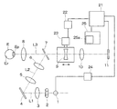
図1は眼底カメラの構成図である。眼底照明光学系においては、光軸L1上に観察用光源1、撮影用光源2、レンズ3、ミラー4が配置され、ミラー4の反射方向の光軸L2上には、リレーレンズ5、6、中央部に開口を有する孔あきミラー7が順次に配列されている。孔あきミラー7の反射方向の光軸L3上には、被検眼Eに対向して対物レンズ8が配置されている。また、眼底照明のための観察用光源1は定常光を発するハロゲンランプ等から成り、また、撮影用光源2は可視光を発するストロボ管等から成っている。
FIG. 1 is a configuration diagram of a fundus camera. In the fundus illumination optical system, an
一方、光軸L3上の孔あきミラー7の後方には、光軸に沿って移動することによりフォーカスを調整するフォーカスレンズ9、撮影レンズ10、眼底Erと共役な位置に配された眼底撮像手段11が順次に配列され、眼底撮影光学系が構成されている。
On the other hand, behind the
眼底撮像手段11の出力はフォーカス状態検出手段21に接続されている。また、フォーカス状態検出手段21の出力はレンズ駆動制御手段22、フォーカスレンズ駆動手段23を介してフォーカスレンズ9に接続され、照明光量制御手段24を介して観察用光源1に接続され、更に表示モニタ25に接続されている。なお、表示モニタ25にはフォーカス検出範囲表示部25aが付設されている。
The output of the fundus imaging means 11 is connected to the focus state detection means 21. The output of the focus state detection means 21 is connected to the focus lens 9 via the lens drive control means 22 and the focus lens drive means 23, connected to the
検者は表示モニタ25に映出された眼底像を観察しながら、観察用光源1を用いて被検眼Eと光学系を内蔵した筐体との位置合わせの微調整を行い、次いでフォーカス調整を行い、撮影用光源2により撮影を実施する。
While examining the fundus image displayed on the
本実施例は、このフォーカス調整を自動的に実行するAF機能を有している。このとき、眼底撮像手段11で得られた眼底像に重畳して、フォーカス検出範囲表示部25aの枠部によりフォーカス検出範囲を検者に提示することで、フォーカス検出位置を視覚的に検者に提示できるため、AF操作性を向上させることができる。
The present embodiment has an AF function for automatically executing this focus adjustment. At this time, the focus detection range is presented to the examiner by superimposing it on the fundus image obtained by the fundus imaging means 11 and the frame portion of the focus detection
このように構成された眼底カメラでは、フォーカス検出は撮影光束により結像される眼底像そのもののコントラスト検出によって行っている。従って、撮像光束の外側の前眼部位を通しフォーカス指標を投影する従来装置とは異なり、被検眼光学系の収差によらないオートフォーカスを行うことができる。 In the fundus camera configured as described above, focus detection is performed by detecting the contrast of the fundus image itself formed by the photographing light flux. Therefore, unlike the conventional apparatus that projects the focus index through the anterior eye part outside the imaging light beam, it is possible to perform autofocus independent of the aberration of the eye optical system to be examined.
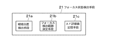
図2に示すように、フォーカス状態検出手段21には、眼底Erの特定位置を検出する眼底位置検出手段21aと、この眼底位置検出手段21aからの信号を基にフォーカス検出範囲を決定するフォーカス検出範囲決定手段21bが設けられている。更に、フォーカス状態検出手段21にはAF評価値が得られたとき、AF評価値とフォーカスレンズ9の位置とを記憶するAF評価値記憶手段21cが内蔵されている。
As shown in FIG. 2, the focus
図3に示すように、眼底位置検出手段21aは眼底像の中から特定部位を抽出するために、眼底像の中で特定部位の標準画像による部位パターンである眼底像パターンメモリ21dを有している。この眼底像パターンメモリ21dに記録されている部位パターンと、眼底撮像手段11からの出力信号とのパターンマッチングにより特定領域の位置情報を得る。また、フォーカス検出範囲決定手段21bは眼底位置検出手段21aによって抽出された眼底像特定部位の出力を基に、フォーカスを合わせる範囲を決定する。しかし図4に示すように、フォーカス検出範囲の大きさの補正を検者が行うために、フォーカス検出範囲決定手段21bは表示モニタ25の画像に対しカーソルの操作により行うフォーカス検出範囲補正手段21eを有していることが望ましい。
As shown in FIG. 3, the fundus
フォーカス状態検出手段21はフォーカス検出範囲決定手段21bで決定されたフォーカス検出範囲のAF評価値を算出し、更にこのときのフォーカスレンズ9の位置の情報をAF評価値記憶手段21cに記憶する。
The focus
図5はAF制御方法のフローチャート図である。図示しないAF開始スイッチによりAF動作の開始が指示されると、ステップS1で眼底像のパターン認識が開始される。ステップS2で眼底位置検出手段21aは眼底撮像手段11からの出力と眼底像パターンメモリ21dに記憶された眼底像特定部位の部位パターンの例えば相関関数等を算出する。そして、その値が閾値以上となる範囲を同範囲とする比較を行い、パターン認識の可否を判断する。
FIG. 5 is a flowchart of the AF control method. When the start of an AF operation is instructed by an AF start switch (not shown), fundus image pattern recognition is started in step S1. In step S2, the fundus
ここで、オートフォーカスが開始された際に、フォーカスレンズ9の位置が合焦時から大きくずれ、パターン認識ができなかった場合にはステップS3に進み、パターン認識ができるまで順次にフォーカスレンズ9を駆動し、その都度パターン認識を行う。 Here, when the autofocus is started, if the position of the focus lens 9 is largely deviated from the in-focus position and the pattern cannot be recognized, the process proceeds to step S3, and the focus lens 9 is sequentially moved until the pattern is recognized. Drive and perform pattern recognition each time.
ステップS2でパターン認識が可能であると判断した場合に、ステップS4でフォーカス検出範囲決定手段21bは眼底位置検出手段21aからの出力を基にフォーカス検出範囲を決定する。フォーカス検出範囲を決定すると、ステップS5でフォーカス状態検出手段21はこのフォーカス検出範囲におけるフォーカスの程度を表すAF評価値を算出する。AF評価値の算出方法については後述するが、算出されたAF評価値はステップS6でAF評価値記憶手段21cに記憶される。
When it is determined in step S2 that pattern recognition is possible, in step S4, the focus detection
図6はコントラスト検出によるフォーカス検出原理の説明図である。このフォーカス検出方式は、輝度信号の特定高周波数成分が合焦時に最大となることを利用したものであり、フォーカス状態検出手段においては、入力された輝度信号の高周波数成分を検出しAF評価値として用いる。横軸はフォーカスレンズ9の位置、縦軸はAF評価値の量をそれぞれ示しており、合焦位置M2においてはAF評価値が最大となり、フォーカスが大きくずれた位置M1では、AF評価値は小さくなる。本実施例では、このコントラスト検出の原理を用いて、人眼光学系の収差に合ったフォーカス補正を行う。 FIG. 6 is an explanatory diagram of the principle of focus detection by contrast detection. This focus detection method utilizes the fact that the specific high-frequency component of the luminance signal is maximized at the time of focusing, and the focus state detection means detects the high-frequency component of the input luminance signal and detects the AF evaluation value. Used as The horizontal axis indicates the position of the focus lens 9, and the vertical axis indicates the amount of the AF evaluation value. The AF evaluation value is maximum at the in-focus position M2, and the AF evaluation value is small at the position M1 where the focus is greatly shifted. Become. In this embodiment, using this contrast detection principle, focus correction that matches the aberration of the human eye optical system is performed.
ステップS7では、前述のコントラスト検出の原理を用い、ステップS6で記憶されたAF評価値の中に、図6に示した位置M2である極大点が含まれるかどうかを検出する。このとき、初回のステップS7での判断は、極大点の判断ができないため、ステップS3に進みフォーカスレンズ9を駆動する。 In step S7, using the above-described principle of contrast detection, it is detected whether or not the AF evaluation value stored in step S6 includes the local maximum point at the position M2 shown in FIG. At this time, since the determination at the first step S7 cannot determine the maximum point, the process proceeds to step S3 to drive the focus lens 9.
ステップS7でAF評価値に極大点が検出された場合に、ステップS8でフォーカス状態検出手段21はフォーカスレンズ9の移動量の算出を行う。ここで、ステップS8におけるフォーカスレンズ9の移動量とは、AF評価値の極大点M2の検出位置までのフォーカスレンズ9の駆動量のことである。ステップS8で算出されたフォーカスレンズ移動量を基に、ステップS9でレンズ駆動制御手段22はフォーカスレンズ駆動手段23に信号を送り、フォーカスレンズ9を駆動しオートフォーカスを完了させる。 When the maximum point is detected in the AF evaluation value in step S7, the focus state detection means 21 calculates the movement amount of the focus lens 9 in step S8. Here, the movement amount of the focus lens 9 in step S8 is the drive amount of the focus lens 9 up to the detection position of the maximum point M2 of the AF evaluation value. Based on the amount of movement of the focus lens calculated in step S8, the lens drive control means 22 sends a signal to the focus lens drive means 23 in step S9 to drive the focus lens 9 and complete autofocus.
ここでは、ステップS8で算出したフォーカスレンズ9の移動量を基に、ステップS9でフォーカスレンズ9を駆動させオートフォーカスを完了させている。しかし、ステップS9の後に、ステップS2〜S5を実行してAF評価値を算出し、最初に極大が判定されたAF評価値との比較を行い、これらのAF評価値の差が或る閾値以下になった場合に、オートフォーカスを完了させるようにしてもよい。 Here, based on the movement amount of the focus lens 9 calculated in step S8, the focus lens 9 is driven in step S9 to complete autofocus. However, after Step S9, Steps S2 to S5 are executed to calculate an AF evaluation value, and compared with the AF evaluation value for which the maximum is first determined, and the difference between these AF evaluation values is less than a certain threshold value. In such a case, autofocus may be completed.
一方、ステップS7でAF評価値に極大点が検出されない場合はステップS3に進み、所定量だけフォーカスレンズ9を駆動する。そして、再びステップS2でパターン認識を行い、ステップS4でフォーカス検出範囲を決定する。これによって、オートフォーカス中に被検眼Eが動いてしまっても、被検眼Eの動きにフォーカス検出範囲を追従させることができる。なお、パターン認識又はAF評価値の極大点検出が所定回数サイクルの中で判別できなかった場合は、エラーとする方法が考えられる。 On the other hand, if the maximum point is not detected in the AF evaluation value in step S7, the process proceeds to step S3, and the focus lens 9 is driven by a predetermined amount. Then, pattern recognition is performed again in step S2, and a focus detection range is determined in step S4. Thereby, even if the eye E moves during autofocus, the focus detection range can follow the movement of the eye E. If pattern recognition or detection of the maximum point of the AF evaluation value cannot be determined within a predetermined number of cycles, an error may be considered.
図7は表示モニタ25に表示された眼底像の説明図であり、眼底部位固有の乳頭部N、中大血管部V、黄斑部Yの位置関係は、個人差があっても大きく変化することはない。また、一般に左右眼ではこの位置関係は左右反転した構成となる。
FIG. 7 is an explanatory diagram of a fundus image displayed on the
図8はフォーカス検出範囲が中大血管部Vの部位パターンである場合のAF評価値についての説明図である。画像中から簡単に高周波成分を検出する方法として、例えば対象画素と縦横斜めに隣接する8画素との輝度信号を比較し、最も大きい差の値を対象画素の有するAF評価値とするAF評価値算出方法がある。画像G1は中大血管部Vが上下方向に存在する場合の画像の一部を切り出した例であり、各画素は”0”、”1”の輝度信号を有している。 FIG. 8 is an explanatory diagram of AF evaluation values when the focus detection range is a site pattern of the middle and large blood vessel V. As a method for easily detecting a high-frequency component from an image, for example, the luminance evaluation signals of the target pixel and eight pixels adjacent vertically and horizontally are compared, and the AF evaluation value having the largest difference value as the AF evaluation value of the target pixel is used. There is a calculation method. The image G1 is an example in which a part of the image is cut out when the middle and large blood vessel portion V exists in the vertical direction, and each pixel has luminance signals of “0” and “1”.
本画像に対してこの検出方法を用いた場合に、画像G2に示すように各画素に対するAF評価値を得ることになる。これらの各画素のAF評価値の総和を、画像全体としてのAF評価値とすることが可能である。 When this detection method is used for the main image, an AF evaluation value for each pixel is obtained as shown in the image G2. The sum of AF evaluation values of these pixels can be used as the AF evaluation value for the entire image.
より簡単、高速にAF評価値を算出する方法として、隣接する2画素と輝度信号を比較し、差がなければ”0”、差があれば”1”とする方法の採用も考えられる。この方法によれば、上述した方法に比べて比較する画素の数が少なくなるため、計算負荷を低減することができる。しかし、画像G1に示した画像に対して、上下方向に隣接する2画素と比較する方法を用いると、その出力は画像G3となり、対象となる中大血管部Vのエッジを検出することができない。 As a simpler and faster method of calculating the AF evaluation value, a method of comparing two adjacent pixels with a luminance signal, “0” if there is no difference, and “1” if there is a difference is also considered. According to this method, the number of pixels to be compared is smaller than that of the method described above, so that the calculation load can be reduced. However, if a method of comparing the image shown in the image G1 with two adjacent pixels in the vertical direction is used, the output is the image G3, and the edge of the target middle and large blood vessel V cannot be detected. .
一方、中大血管部Vが左右方向に存在するような画像G4に対して適用した場合には、その出力は画像G5のようになり、上述した方法で、AF評価値を算出した画像G2と同様の結果を得ることができる。即ち、上述のように方向依存性のある検出方法を選択することは、演算時間の短縮が可能となる反面で、対象となる画像を適切に選択しなければならない。 On the other hand, when applied to the image G4 in which the middle and large blood vessels V are present in the left-right direction, the output is the image G5, and the image G2 obtained by calculating the AF evaluation value by the above-described method Similar results can be obtained. That is, selecting a direction-dependent detection method as described above can reduce the calculation time, but the target image must be appropriately selected.
このように、画像G1、G2に対して、隣の画素値との輝度の差を画像G2、G5のようにマッピングし、この差が大きいほど、隣の画素との輝度差が大きいことを表し、その総和を画像全体のAF評価値としている。 In this manner, the difference in luminance between the adjacent pixel values is mapped to the images G1 and G2 as in the images G2 and G5, and the larger the difference is, the larger the luminance difference from the adjacent pixel is. The sum is used as the AF evaluation value for the entire image.
本実施例で例に挙げた中大血管部Vは、眼底Er上で黄斑部Yをほぼ中心とした円弧状の走行を示し、更に太い幹となる部位分は乳頭部N付近に存在する。このことから、ほぼ±45°の方向に中大血管部Vのエッジが存在すため、その方向に選択性を有する検出方法を採ることにより、AF評価値の感度を落とすことなく、低負荷かつ高速なオートフォーカスの達成が可能となる。 The middle / large blood vessel portion V exemplified in the present embodiment shows an arcuate running around the macular portion Y on the fundus Er, and a portion that becomes a thicker trunk exists near the nipple N. From this, there is an edge of the middle-large blood vessel portion V in the direction of approximately ± 45 °. Therefore, by adopting a detection method having selectivity in that direction, the load of the AF evaluation value is reduced without reducing the sensitivity. High-speed autofocus can be achieved.
ここでは、眼底像のパターン認識に眼底Er上の中大血管部Vを用いたが、他の部位、例えば乳頭部Nや黄斑部Yの部位パターンを眼底像パターンメモリ21dに記憶させておき、それらに対してオートフォーカスを行うことも可能である。
Here, the middle and large blood vessels V on the fundus Er are used for pattern recognition of the fundus image. However, other site portions, for example, part patterns of the nipple N and the macula Y are stored in the fundus
このように、パターン認識によってフォーカス検出範囲を自動で決定することで、オートフォーカスの操作性の向上が達成できる。また、被検眼Eの動きにフォーカス検出位置を追従させることができるので、フォーカス精度の向上が可能となる。 Thus, by automatically determining the focus detection range by pattern recognition, it is possible to improve the operability of autofocus. Further, since the focus detection position can be made to follow the movement of the eye E, it is possible to improve the focus accuracy.
また、フォーカス状態検出手段21はAF評価値を計算する際に、各画素の輝度値を参照しているため、決定したフォーカス検出範囲の輝度値が飽和が生じているか否かを検出するようにしてもよい。また、飽和を起こしている場合には、フォーカス状態検出手段21は照明光量制御手段24に信号を送信し、観察用光源1の光量を調節することで、より高精度なオートフォーカスを実現することができる。例えば、白飛びが生じ易い乳頭部Nでコントラスト検出を行う際に、照明光学系の光量を調整することで、高精度かつ診断価値の高い眼底像が得られる。
In addition, since the focus
実施例1では、眼底Er上の1つの特定部位に対してパターン認識を行う例を説明した。本実施例2では、オートフォーカス開始前に検者が眼底Er上のどの部位にフォーカス検出範囲を設定するかを選択し、その選択に基づいてフォーカス検出範囲を決定してオートフォーカスを実行する。 In the first embodiment, an example in which pattern recognition is performed on one specific part on the fundus Er has been described. In the second embodiment, before starting the autofocus, the examiner selects which part on the fundus Er the focus detection range is to be set, determines the focus detection range based on the selection, and executes autofocus.
本実施例2では、眼底像パターンメモリ21dは複数の眼底像パターン、例えば乳頭部N、黄斑部Y、中大血管部Vの部位パターンを有している。検者は予め症例に応じてフォーカスを行うべき部位を表示モニタ25上でカーソル等による部位選択手段によって選択するが、それは眼底位置検出手段21aに設けられた複数の眼底像パターンからの1つを選択することに相当する。更に、眼底撮像手段11の出力に基づいて選択された眼底像パターンの位置を検出し、フォーカス検出範囲決定手段21bに引き渡すが、この動作及びそれ以降の動作は実施例1と同様である。
In the second embodiment, the fundus
検者は1つの眼底部位を選択するようにしたが、複数の部位を選択することも可能である。この場合に、複数の部位に対してAF評価値を算出し、その和の値を総合評価値とすればよい。この総合評価値の極大値を検出することで、検者が選択した複数の部位に対し平均的にフォーカスが合った画像を得ることができる。これにより、検者の着目したい部位にフォーカスした眼底像を撮影でき、診断価値の高い眼底像を検者は得ることができる。 Although the examiner selects one fundus region, it is also possible to select a plurality of regions. In this case, an AF evaluation value may be calculated for a plurality of parts, and the sum value may be used as a comprehensive evaluation value. By detecting the maximum value of the comprehensive evaluation value, it is possible to obtain an image in which a plurality of parts selected by the examiner are focused on average. As a result, the fundus image focused on the region that the examiner wants to focus on can be photographed, and the examiner can obtain a fundus image with high diagnostic value.
このように、検者が診断において特に着目したい部位をパターン認識し、フォーカス検出範囲を決定することで、診断価値の高い眼底像が得られる。即ち、眼底像の中で比較的高周波成分を多く持つ乳頭部N、中大血管部V、黄斑部Yにおいて、適切なフォーカス検出範囲を決定することができ、高精度なコントラスト検出が可能となる。 In this way, a fundus image having a high diagnostic value can be obtained by pattern-recognizing a site that the examiner particularly wants to focus on in diagnosis and determining the focus detection range. That is, an appropriate focus detection range can be determined in the nipple N, middle large blood vessel V, and macular Y having a relatively high frequency component in the fundus image, and high-precision contrast detection is possible. .
特に、凹凸の個人差が大きい乳頭部Nではなく、個人差の小さい中大血管部Vを主に検出することで、高精度なコントラスト検出が可能となる。更に、中大血管部Vの走行方向も容易に特定できるため、中大血管部Vに直交する方向のコントラストを検出することで、高精度かつ計算負荷の少ない高速かつ低コストなコントラスト検出が可能となる。 In particular, it is possible to detect contrast with high accuracy by mainly detecting the middle and large blood vessels V having a small individual difference instead of the nipple N having a large individual difference in unevenness. Furthermore, since the traveling direction of the middle and large blood vessels V can be easily specified, by detecting the contrast in the direction perpendicular to the middle and large blood vessels V, high-speed and low-cost contrast detection can be performed with high accuracy and low calculation load. It becomes.
また、複数の眼底部位の中から検者はフォーカス検出範囲を選択することにより、検者の着目している病変に応じた診断価値の高い画像を得ることができる。 In addition, the examiner can obtain an image with high diagnostic value corresponding to the lesion focused on by the examiner by selecting a focus detection range from among a plurality of fundus sites.
実施例2では、検者はオートフォーカス開始前にフォーカス検出範囲を選択している。本実施例3では、検者はパターン認識された特定部位の中からフォーカス検出範囲を選択しオートフォーカスを行う。 In the second embodiment, the examiner selects the focus detection range before starting the autofocus. In the third embodiment, the examiner selects a focus detection range from the specific parts whose pattern is recognized, and performs autofocus.
実施例1においては実施例2と同様に、眼底像パターンメモリ21dは複数の眼底像パターン、例えば乳頭部N、黄斑部Y、中大血管部Vの部位パターンを有している。本実施例3では、眼底撮像手段11の出力に対して複数の眼底像パターンの位置を検出し、フォーカス検出範囲決定手段21bに引き渡すことが先の実施例1、2と異なっている。
In the first embodiment, similarly to the second embodiment, the fundus
本実施例3では、フォーカス検出範囲決定手段21bは図9に示すように、フォーカス検出範囲補正手段21eとフォーカス検出範囲選択手段21fを備えている。表示モニタ25上のフォーカス検出範囲表示部25aは、眼底位置検出手段21aによって抽出された複数の眼底像特定部位を検者に提示する。検者はそれらの中からカーソルによるフォーカス検出範囲選択手段21fを用いて、フォーカス検出範囲を設定すべき部位を1つ選択する。ここで、検者に眼底像特定部位を提示するタイミングとしては、所定の個数分のパターン認識が検出されたときや、フォーカスレンズ9がその可動範囲を全て移動したときなどが考えられる。
In the third embodiment, the focus detection
また、フォーカス検出範囲の大きさの補正を検者が行うためのフォーカス検出範囲補正手段21eでは、フォーカス検出範囲の位置及び大きさを検者が手動で補正することができ、検者の着目すべき部位に正しく合焦した眼底像を得ることができる。 Further, the focus detection range correction means 21e for the examiner to correct the size of the focus detection range allows the examiner to manually correct the position and size of the focus detection range. It is possible to obtain a fundus image that is correctly focused on the power region.
また、検者は1つの眼底部位を選択したが、実施例2と同様に複数の部位を選択することも可能である。選択された眼底像特定部位をフォーカス検出範囲決定手段21bに引き渡す動作、またそれ以降の動作は実施例1と同様である。
In addition, although the examiner has selected one fundus region, it is also possible to select a plurality of regions as in the second embodiment. The operation for handing over the selected fundus image specific part to the focus detection
実施例2、3では、複数のパターン認識された眼底像部位の中から、検者が選択した1つ又は複数のフォーカス検出範囲のAF評価値を算出する例を説明した。しかし実施例4では、複数のパターン認識された眼底像の全ての部位パターンに対してAF評価値を算出、評価し、オートフォーカスを行う。 In the second and third embodiments, the example has been described in which the AF evaluation values of one or more focus detection ranges selected by the examiner are calculated from a plurality of pattern-recognized fundus image regions. However, in the fourth embodiment, AF evaluation values are calculated and evaluated for all part patterns of a plurality of fundus images whose patterns are recognized, and autofocus is performed.
本実施例4では、眼底位置検出手段21aが抽出した複数の眼底像特定部に対し、フォーカス状態検出手段21はそれぞれの部位に対するAF評価値を算出する。フォーカス状態検出手段21はそれらの和の値を総合評価値とし、この総合評価値の極大値を検出することで、パターン認識した複数の部位に平均的にフォーカスの合った画像を得ることができる。
In the fourth embodiment, for a plurality of fundus image specifying units extracted by the fundus
また実施例4では、図10に示すようにフォーカス検出範囲決定手段21bにフォーカス検出範囲絞り込み手段21gが設けられている。眼底位置検出手段21aが抽出した眼底像特定部に対し、フォーカス検出範囲絞り込み手段21gは最もAF評価値の高い1つの特定部位を自動的にフォーカス検出範囲として決定し、フォーカス状態検出手段21に引き渡す。選択された眼底像特定部位をフォーカス検出範囲決定手段21bに引き渡す動作、またそれ以降の動作は先の実施例と同様である。これにより、自動的に良好な合焦状態の眼底像を撮影できるので、AF操作性の高い眼底カメラが得られる。
In Example 4, as shown in FIG. 10, the focus detection range narrowing means 21g is provided in the focus detection range determination means 21b. For the fundus image specifying unit extracted by the fundus
自動でフォーカス検出範囲を決定することで、AF操作性を向上させることができる。 AF operability can be improved by automatically determining the focus detection range.
これまでの実施例1〜4では、眼底位置検出手段21aによるパターン認識のみによって眼底像特定部位の位置検出を行う例を説明した。本実施例5では、乳頭部Nのパターン認識と左右眼検出とを組み合わせて、特定高周波成分が多く含まれる中大血管部Vを検出しオートフォーカスを行っている。
In Examples 1 to 4 described so far, the example in which the position of the fundus image specific part is detected only by the pattern recognition by the fundus
図11は実施例5における眼底カメラの外観図を示し、基台31上には矢印方向の前後左右に移動可能な架台32が載置されている。この架台32上には、図1に示す眼底カメラの光学系を内蔵した筐体33及び表示モニタ25が載置されていると共に、撮影スイッチ34を有する操作桿35が設けられている。
FIG. 11 is an external view of a fundus camera according to the fifth embodiment, and a
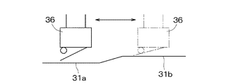
検者は操作桿35を操作し、架台32を左右眼に合わせて水平面上で左右方向に調整する。基台31と架台32の間には、左右眼検出手段36が設けられていることから、筐体33の左右位置を検出し、被検者Sの左右眼のうち、何れの被検眼Eに対して観察・撮影がなされているかを検知することができる。
The examiner operates the
図12は左右眼検出手段36による検出方法の説明図を示し、基台31の上面には高低差を有する低い部分31aと高い部分31bとが設けられている。架台32の底面に設けられた例えばマイクロスイッチから成る左右眼検出手段36が、基台31の低い部分31aの上部に位置するときはオフ状態に、高い部分31bに位置するときはオン状態になる。つまり、低い部分31aを左側、高い部分31bを右側に設けることにより、左右眼検出手段36のオン/オフを検出し、筐体33が対向している左右の被検眼を検出することができる。
FIG. 12 is an explanatory diagram of a detection method by the left and right eye detection means 36, and a
ここで、左右眼検出手段36による左右眼検出と、眼底位置検出手段21aによる乳頭部Nのパターン認識によって、フォーカス検出範囲、特に図7に示す中大血管部Vを検出する方法を説明する。 Here, a method of detecting the focus detection range, particularly the middle / large blood vessel portion V shown in FIG. 7, by left and right eye detection by the left and right eye detection means 36 and pattern recognition of the nipple N by the fundus position detection means 21a will be described.
眼底Er上で1つの特定部位を検出し、かつ左右眼の何れを観察しているかが判定できれば、眼底Erの構造を予想することができる。従って、左右眼検出手段36による左右眼検出と乳頭部Nのパターン認識とによって、中大血管部Vを検出することができる。検出された中大血管部Vをフォーカス検出範囲決定手段21bに引き渡す動作、またそれ以降の動作は先の実施例と同様である。
If one specific part is detected on the fundus Er and it can be determined which of the left and right eyes is being observed, the structure of the fundus Er can be predicted. Therefore, the middle and large blood vessel portion V can be detected by the left and right eye detection by the left and right eye detection means 36 and the pattern recognition of the nipple N. The operation of handing over the detected middle / large blood vessel portion V to the focus detection
本実施例5では、容易なパターン認識が可能である乳頭部Nのみを検出し、そこから他の眼底Er上の部位を予想してフォーカス検出範囲として決定するため、個人差によって眼底Er上の特定部位とフォーカス検出範囲とがずれる可能性がある。そこで、フォーカス検出範囲補正手段21eによってフォーカス検出範囲の位置及び大きさを検者が手動で補正することで、検者が着目すべき部位に正しくフォーカスした眼底像を得ることができる。
In the fifth embodiment, only the papilla N that allows easy pattern recognition is detected, and other regions on the fundus Er are predicted therefrom and determined as a focus detection range. There is a possibility that the specific part and the focus detection range are shifted. Therefore, when the examiner manually corrects the position and size of the focus detection range by the focus detection
このように、パターン認識のし易い乳頭部Nと左右眼検出によって、中大血管部V或いは黄斑部Yを特定し、フォーカス検出範囲とすることで、計算負荷が軽くなり演算時間が短く、高速なオートフォーカスが可能となる。 In this way, by specifying the middle and large blood vessels V or the macular portion Y by detecting the nipple N and the left and right eyes, which are easy to recognize patterns, and making the focus detection range, the calculation load is reduced, the calculation time is short, and the high speed is achieved. Auto focus is possible.
9 フォーカスレンズ
11 眼底撮像手段
21 フォーカス状態検出手段
21a 眼底位置検出手段
21b フォーカス検出範囲決定手段
21c AF評価値記憶手段
21d 眼底像パターンメモリ
21e フォーカス検出範囲補正手段
21f フォーカス検出範囲選択手段
21g フォーカス検出範囲絞り込み手段
24 照明光量制御手段
25 表示モニタ
25a フォーカス検出範囲表示部
DESCRIPTION OF SYMBOLS 9
Claims (13)
Priority Applications (5)
| Application Number | Priority Date | Filing Date | Title |
|---|---|---|---|
| JP2009201290A JP5388765B2 (en) | 2009-09-01 | 2009-09-01 | Fundus camera |
| PCT/JP2010/005332 WO2011027531A1 (en) | 2009-09-01 | 2010-08-30 | Fundus camera |
| EP10813483.4A EP2473093A4 (en) | 2009-09-01 | 2010-08-30 | Fundus camera |
| US13/393,001 US20120154748A1 (en) | 2009-09-01 | 2010-08-30 | Fundus camera |
| CN201080039000.2A CN102481097B (en) | 2009-09-01 | 2010-08-30 | Fundus camera |
Applications Claiming Priority (1)
| Application Number | Priority Date | Filing Date | Title |
|---|---|---|---|
| JP2009201290A JP5388765B2 (en) | 2009-09-01 | 2009-09-01 | Fundus camera |
Related Child Applications (1)
| Application Number | Title | Priority Date | Filing Date |
|---|---|---|---|
| JP2013212907A Division JP5777681B2 (en) | 2013-10-10 | 2013-10-10 | Control apparatus and control method |
Publications (2)
| Publication Number | Publication Date |
|---|---|
| JP2011050531A JP2011050531A (en) | 2011-03-17 |
| JP5388765B2 true JP5388765B2 (en) | 2014-01-15 |
Family
ID=43649087
Family Applications (1)
| Application Number | Title | Priority Date | Filing Date |
|---|---|---|---|
| JP2009201290A Expired - Fee Related JP5388765B2 (en) | 2009-09-01 | 2009-09-01 | Fundus camera |
Country Status (5)
| Country | Link |
|---|---|
| US (1) | US20120154748A1 (en) |
| EP (1) | EP2473093A4 (en) |
| JP (1) | JP5388765B2 (en) |
| CN (1) | CN102481097B (en) |
| WO (1) | WO2011027531A1 (en) |
Families Citing this family (23)
| Publication number | Priority date | Publication date | Assignee | Title |
|---|---|---|---|---|
| JP5539123B2 (en) * | 2010-08-31 | 2014-07-02 | キヤノン株式会社 | Ophthalmologic photographing apparatus and photographing method using ophthalmic photographing apparatus |
| EP2863480B1 (en) | 2010-09-07 | 2018-11-07 | Murata Manufacturing Co., Ltd. | Communication terminal apparatus comprising an antenna device |
| JP5943785B2 (en) * | 2012-09-12 | 2016-07-05 | キヤノン株式会社 | IMAGING DEVICE, IMAGING SYSTEM, IMAGE PROCESSING DEVICE, AND IMAGING DEVICE CONTROL METHOD |
| JP2014079392A (en) * | 2012-10-17 | 2014-05-08 | Canon Inc | Ophthalmology imaging apparatus |
| JP2014083376A (en) * | 2012-10-26 | 2014-05-12 | Canon Inc | Ophthalmologic apparatus, and control method |
| JP2014083358A (en) * | 2012-10-26 | 2014-05-12 | Canon Inc | Ophthalmologic apparatus, ophthalmology control method, and program |
| JP2014094118A (en) * | 2012-11-09 | 2014-05-22 | Canon Inc | Ophthalmologic photography apparatus and method |
| JP2014113422A (en) * | 2012-12-12 | 2014-06-26 | Canon Inc | Ophthalmological photographing apparatus, and control method and program of ophthalmological photographing apparatus |
| JP6296683B2 (en) * | 2013-01-31 | 2018-03-20 | キヤノン株式会社 | Ophthalmic apparatus and control method |
| CN103353667B (en) | 2013-06-28 | 2015-10-21 | 北京智谷睿拓技术服务有限公司 | Imaging adjustment Apparatus and method for |
| CN103353663B (en) | 2013-06-28 | 2016-08-10 | 北京智谷睿拓技术服务有限公司 | Imaging adjusting apparatus and method |
| CN103353677B (en) | 2013-06-28 | 2015-03-11 | 北京智谷睿拓技术服务有限公司 | Imaging device and method thereof |
| CN103424891B (en) | 2013-07-31 | 2014-12-17 | 北京智谷睿拓技术服务有限公司 | Imaging device and method |
| CN103431840B (en) * | 2013-07-31 | 2016-01-20 | 北京智谷睿拓技术服务有限公司 | Eye optical parameter detecting system and method |
| CN103439801B (en) | 2013-08-22 | 2016-10-26 | 北京智谷睿拓技术服务有限公司 | Sight protectio imaging device and method |
| CN103431980A (en) | 2013-08-22 | 2013-12-11 | 北京智谷睿拓技术服务有限公司 | Eyesight protection imaging system and method |
| CN103605208B (en) | 2013-08-30 | 2016-09-28 | 北京智谷睿拓技术服务有限公司 | content projection system and method |
| CN103500331B (en) | 2013-08-30 | 2017-11-10 | 北京智谷睿拓技术服务有限公司 | Based reminding method and device |
| CN103558909B (en) | 2013-10-10 | 2017-03-29 | 北京智谷睿拓技术服务有限公司 | Interaction projection display packing and interaction projection display system |
| JP5777681B2 (en) * | 2013-10-10 | 2015-09-09 | キヤノン株式会社 | Control apparatus and control method |
| CN110930446B (en) * | 2018-08-31 | 2024-03-19 | 福州依影健康科技有限公司 | Pretreatment method and storage device for quantitative analysis of fundus images |
| CN109889714A (en) * | 2019-03-15 | 2019-06-14 | 杭州视辉科技有限公司 | Eye-ground photography device and its judge the method that electric voltage exception and auto-focusing are taken pictures |
| WO2021010345A1 (en) * | 2019-07-16 | 2021-01-21 | 株式会社ニデック | Ophthalmologic imaging apparatus |
Family Cites Families (16)
| Publication number | Priority date | Publication date | Assignee | Title |
|---|---|---|---|---|
| JPH01178237A (en) * | 1988-01-07 | 1989-07-14 | Kowa Co | Ophthalmic measuring apparatus |
| JPH07227380A (en) * | 1994-02-21 | 1995-08-29 | Canon Inc | Eyeground camera |
| WO1999013763A1 (en) * | 1997-09-17 | 1999-03-25 | Kabushiki Kaisha Topcon | Ophthalmological photographng apparatus |
| JP3783814B2 (en) * | 1997-12-26 | 2006-06-07 | 株式会社トプコン | Ophthalmic equipment |
| JP2003532461A (en) * | 2000-04-14 | 2003-11-05 | フォヴィオプティックス インコーポレイテッド | Non-invasive measurement method using retinal image |
| US20050010091A1 (en) * | 2003-06-10 | 2005-01-13 | Woods Joe W. | Non-invasive measurement of blood glucose using retinal imaging |
| EP1487323B1 (en) * | 2002-03-28 | 2015-04-22 | Heidelberg Engineering GmbH | Method for examining the ocular fundus |
| WO2004056278A2 (en) * | 2002-12-19 | 2004-07-08 | Kolanko Christopher J | Method for diagnosing a disease state using ocular characteristics |
| JP4359489B2 (en) * | 2003-11-28 | 2009-11-04 | 株式会社ニデック | Fundus camera |
| JP4377745B2 (en) * | 2004-05-14 | 2009-12-02 | オリンパス株式会社 | Electronic endoscope |
| JP4628763B2 (en) * | 2004-12-01 | 2011-02-09 | 株式会社ニデック | Fundus camera |
| GB0517948D0 (en) * | 2005-09-03 | 2005-10-12 | Keeler Ltd | Imaging apparatus, portable image capture device and method of assembling composite images from component images |
| JP4797522B2 (en) * | 2005-09-08 | 2011-10-19 | カシオ計算機株式会社 | Imaging apparatus and program thereof |
| KR100806690B1 (en) * | 2006-03-07 | 2008-02-27 | 삼성전기주식회사 | Auto focusing method and auto focusing apparatus therewith |
| JP4869757B2 (en) * | 2006-03-24 | 2012-02-08 | 株式会社トプコン | Fundus observation device |
| US7824035B2 (en) * | 2008-06-02 | 2010-11-02 | Nidek Co., Ltd. | Ophthalmic photographing apparatus |
-
2009
- 2009-09-01 JP JP2009201290A patent/JP5388765B2/en not_active Expired - Fee Related
-
2010
- 2010-08-30 EP EP10813483.4A patent/EP2473093A4/en not_active Withdrawn
- 2010-08-30 WO PCT/JP2010/005332 patent/WO2011027531A1/en active Application Filing
- 2010-08-30 CN CN201080039000.2A patent/CN102481097B/en not_active Expired - Fee Related
- 2010-08-30 US US13/393,001 patent/US20120154748A1/en not_active Abandoned
Also Published As
| Publication number | Publication date |
|---|---|
| CN102481097A (en) | 2012-05-30 |
| EP2473093A1 (en) | 2012-07-11 |
| US20120154748A1 (en) | 2012-06-21 |
| WO2011027531A1 (en) | 2011-03-10 |
| CN102481097B (en) | 2015-05-06 |
| JP2011050531A (en) | 2011-03-17 |
| EP2473093A4 (en) | 2015-08-19 |
Similar Documents
| Publication | Publication Date | Title |
|---|---|---|
| JP5388765B2 (en) | Fundus camera | |
| JP5371638B2 (en) | Ophthalmic imaging apparatus and method | |
| JP6518054B2 (en) | Ophthalmic device | |
| JP2008110156A (en) | Ophthalmologic photographing apparatus | |
| JP5430260B2 (en) | Ophthalmic imaging apparatus and ophthalmic imaging method | |
| JP5101370B2 (en) | Fundus photographing device | |
| JP2016077337A (en) | Ophthalmologic apparatus and control method for ophthalmologic apparatus | |
| JP2016185192A (en) | Ophthalmologic apparatus, and control method of ophthalmologic apparatus | |
| JP5953740B2 (en) | Fundus examination device | |
| JP5566711B2 (en) | Ophthalmic equipment | |
| JP5355220B2 (en) | Fundus photographing device | |
| JP6003234B2 (en) | Fundus photographing device | |
| JP6518132B2 (en) | Ophthalmic imaging device | |
| JP2013244363A (en) | Fundus photographing apparatus | |
| JP5916301B2 (en) | Optometry equipment | |
| JP2014090822A (en) | Ophthalmic imaging apparatus, imaging control device, and imaging control method | |
| JP5777681B2 (en) | Control apparatus and control method | |
| JP2012223428A (en) | Ophthalmic apparatus | |
| JP5587478B2 (en) | Ophthalmic imaging apparatus and control method thereof | |
| JP6456208B2 (en) | Ophthalmic apparatus and method for controlling ophthalmic apparatus | |
| JP6733292B2 (en) | Ophthalmic device and ophthalmic device control program | |
| JP7118197B2 (en) | ophthalmic equipment | |
| JP6140947B2 (en) | Ophthalmic apparatus and ophthalmic imaging method | |
| JP2017196305A (en) | Ophthalmologic apparatus | |
| JP2017196304A (en) | Ophthalmic apparatus and ophthalmic apparatus control program |
Legal Events
| Date | Code | Title | Description |
|---|---|---|---|
| A621 | Written request for application examination |
Free format text: JAPANESE INTERMEDIATE CODE: A621 Effective date: 20120831 |
|
| TRDD | Decision of grant or rejection written | ||
| A01 | Written decision to grant a patent or to grant a registration (utility model) |
Free format text: JAPANESE INTERMEDIATE CODE: A01 Effective date: 20130910 |
|
| A61 | First payment of annual fees (during grant procedure) |
Free format text: JAPANESE INTERMEDIATE CODE: A61 Effective date: 20131008 |
|
| R151 | Written notification of patent or utility model registration |
Ref document number: 5388765 Country of ref document: JP Free format text: JAPANESE INTERMEDIATE CODE: R151 |
|
| LAPS | Cancellation because of no payment of annual fees |