JP5388311B2 - Solar cell module support structure, solar power generation system using the support structure, and solar cell module installation method - Google Patents
Solar cell module support structure, solar power generation system using the support structure, and solar cell module installation method Download PDFInfo
- Publication number
- JP5388311B2 JP5388311B2 JP2011156843A JP2011156843A JP5388311B2 JP 5388311 B2 JP5388311 B2 JP 5388311B2 JP 2011156843 A JP2011156843 A JP 2011156843A JP 2011156843 A JP2011156843 A JP 2011156843A JP 5388311 B2 JP5388311 B2 JP 5388311B2
- Authority
- JP
- Japan
- Prior art keywords
- solar cell
- cell module
- row
- frame member
- fixing
- Prior art date
- Legal status (The legal status is an assumption and is not a legal conclusion. Google has not performed a legal analysis and makes no representation as to the accuracy of the status listed.)
- Expired - Fee Related
Links
Images


Classifications
-
- Y—GENERAL TAGGING OF NEW TECHNOLOGICAL DEVELOPMENTS; GENERAL TAGGING OF CROSS-SECTIONAL TECHNOLOGIES SPANNING OVER SEVERAL SECTIONS OF THE IPC; TECHNICAL SUBJECTS COVERED BY FORMER USPC CROSS-REFERENCE ART COLLECTIONS [XRACs] AND DIGESTS
- Y02—TECHNOLOGIES OR APPLICATIONS FOR MITIGATION OR ADAPTATION AGAINST CLIMATE CHANGE
- Y02B—CLIMATE CHANGE MITIGATION TECHNOLOGIES RELATED TO BUILDINGS, e.g. HOUSING, HOUSE APPLIANCES OR RELATED END-USER APPLICATIONS
- Y02B10/00—Integration of renewable energy sources in buildings
- Y02B10/10—Photovoltaic [PV]
-
- Y—GENERAL TAGGING OF NEW TECHNOLOGICAL DEVELOPMENTS; GENERAL TAGGING OF CROSS-SECTIONAL TECHNOLOGIES SPANNING OVER SEVERAL SECTIONS OF THE IPC; TECHNICAL SUBJECTS COVERED BY FORMER USPC CROSS-REFERENCE ART COLLECTIONS [XRACs] AND DIGESTS
- Y02—TECHNOLOGIES OR APPLICATIONS FOR MITIGATION OR ADAPTATION AGAINST CLIMATE CHANGE
- Y02E—REDUCTION OF GREENHOUSE GAS [GHG] EMISSIONS, RELATED TO ENERGY GENERATION, TRANSMISSION OR DISTRIBUTION
- Y02E10/00—Energy generation through renewable energy sources
- Y02E10/50—Photovoltaic [PV] energy
Landscapes
- Photovoltaic Devices (AREA)
- Roof Covering Using Slabs Or Stiff Sheets (AREA)
Description
本発明は、複数の太陽電池モジュールを行列方向に並べて支持する太陽電池モジュール支持構造、その支持構造を用いた太陽光発電システム及び太陽電池モジュールの設置方法に関する。 The present invention relates to a solar cell module support structure that supports a plurality of solar cell modules arranged in a matrix direction, a solar power generation system using the support structure, and a solar cell module installation method.
この種の太陽光発電システムとしては、例えば複数の桟を平行に並べて固定した架台を構成し、この架台の各桟の間に複数の太陽電池モジュールを架け渡して、各太陽電池モジュールを支持したものがある。 As this type of solar power generation system, for example, a base in which a plurality of crosspieces are arranged and fixed in parallel is configured, and a plurality of solar cell modules are bridged between the crosspieces of the base and each solar cell module is supported. There is something.
そのような架台は、架台そのものの強度が確保されるように桟の構造や材質等を決定している。また、太陽電池モジュールについても、太陽電池モジュールそのものの強度を確保したり、太陽電池パネルを保護するべく、太陽電池パネルを枠部材で縁取った構造が採用されている。 Such a frame determines the structure and material of the crosspiece so that the strength of the frame itself is ensured. Moreover, also about the solar cell module, the structure which bordered the solar cell panel with the frame member is employ | adopted in order to ensure the intensity | strength of a solar cell module itself or to protect a solar cell panel.
ところが、太陽電池モジュールを架台に搭載した場合は、太陽電池モジュールの枠と架台の桟などの類似した部材が重なり、太陽光発電システム全体の部品点数が無駄に多くなった。 However, when the solar cell module is mounted on the gantry, similar members such as the frame of the solar cell module and the frame of the gantry overlap, and the number of parts of the entire photovoltaic power generation system increases.
一方、太陽電池モジュールの枠部材を簡単な金具等で下地に直接固定する構造では、架台を必要としない。例えば、特許文献1では、太陽電池モジュールを2本の垂木上に載せて、太陽電池モジュールの枠部材の4箇所をそれぞれの据付部材で2本の垂木に固定している。また、小型の太陽電池モジュールを1本の垂木上に載せる場合は、小型の太陽電池モジュールの枠部材の2箇所をそれぞれの据付部材で1本の垂木に固定し、また小型の太陽電池モジュールの枠部材を連結金具を介して隣りの他の太陽電池モジュールの枠部材に連結して、小型の太陽電池モジュールの支持強度を高めている。
On the other hand, in a structure in which the frame member of the solar cell module is directly fixed to the base with a simple metal fitting or the like, no frame is required. For example, in
しかしながら、特許文献1のような固定構造は、複数の太陽電池モジュールを一列に並べて固定するのに適していても、複数の太陽電池モジュールを行列方向に並べて固定するのには適していない。例えば、各列間のスペースを十分に広くしなければ、据付部材や連結金具の取付け作業を行うことができず、太陽光発電に寄与しない無駄なスペースの拡大を避けることができない。
However, although the fixing structure as in
このように太陽電池モジュールを架台に搭載した場合は、太陽電池モジュールの枠と架台の桟などの類似した部材が重なり、太陽光発電システム全体の部品点数が無駄に多くなった。 When the solar cell module is mounted on the gantry in this way, similar members such as a frame of the solar cell module and a frame of the gantry overlap, and the number of parts of the entire photovoltaic power generation system increases.
また、特許文献1の固定構造では、複数の太陽電池モジュールを一列に並べて固定するのに適していても、複数の太陽電池モジュールを行列方向に並べて固定するのには適しておらず、太陽光発電に寄与しない無駄なスペースの拡大を避けることができなかった。
In addition, the fixing structure of
そこで、本発明は、上記従来の問題点に鑑みてなされたものであり、複数の太陽電池モジュールを行列方向に並べて固定するのに適していて、部品点数を抑えることが可能な太陽電池モジュール支持構造、その支持構造を用いた太陽光発電システム及び太陽電池モジュールの設置方法を提供することを目的とする。 Accordingly, the present invention has been made in view of the above-described conventional problems, and is suitable for fixing a plurality of solar cell modules side by side in a matrix direction and capable of suppressing the number of components. An object is to provide a structure, a photovoltaic power generation system using the support structure, and a method for installing a solar cell module.
上記課題を解決するために、本発明の太陽電池モジュール支持構造は、複数の太陽電池モジュールを行列方向に並べて支持する太陽電池モジュール支持構造であって、列方向に並ぶ2枚の太陽電池モジュールの枠部材の間に配置されて、前記列方向に並ぶ2枚の太陽電池モジュールの枠部材に係合して、前記列方向に並ぶ2枚の太陽電池モジュールを連結することができるように、相反するそれぞれの外側方向に向く2つの係合部が形成された連結具と、前記連結具を支持して土台に固定するものであって、前記連結具の支持位置が列方向に移動可能な構造が設けられた固定具とを備え、前記連結具及び前記固定具が行方向及び列方向に複数配列されている。 In order to solve the above-described problems, a solar cell module support structure of the present invention is a solar cell module support structure that supports a plurality of solar cell modules arranged in a matrix direction, and includes two solar cell modules arranged in a column direction. It is disposed between the frame members, and engages with the frame members of the two solar cell modules arranged in the column direction so that the two solar cell modules arranged in the column direction can be connected to each other. A connecting tool formed with two engaging portions facing outwardly from each other, and a structure for supporting the connecting tool and fixing it to a base, wherein the supporting position of the connecting tool is movable in the row direction And a plurality of the coupling tools and the fixing tools are arranged in the row direction and the column direction.
連結具は、列方向に並ぶ2枚の太陽電池モジュールの枠部材の間に配置されて、前記列方向に並ぶ2枚の太陽電池モジュールの枠部材に係合して、前記列方向に並ぶ2枚の太陽電池モジュールを連結することができるように、相反するそれぞれの外側方向に向く2つの係合部が形成されているので、列方向に並べられた各太陽電池モジュールを一体的に支持することがでる。また、固定具は、連結具の支持位置が列方向に移動可能な構造が設けられているので、連結具を列方向に並ぶ2枚の太陽電池モジュールの枠部材の間に配置することが容易になる。また、連結具及び固定具が行方向及び列方向に複数配列されているので、行列方向に並べられた各太陽電池モジュールを土台上に設置することが可能になる。これらから、従来の架台の桟等を必要とせず、部品点数の無駄な増加を抑えることができ、太陽光発電に寄与しない無駄なスペースを抑えることができる。 The connector is disposed between the frame members of the two solar cell modules arranged in the row direction, engages with the frame members of the two solar cell modules arranged in the row direction, and is arranged in the row direction. Since the two engaging portions facing each other in the opposite direction are formed so that the solar cell modules can be connected to each other, the solar cell modules arranged in the column direction are integrally supported. It comes out. Further, since the fixture is provided with a structure in which the support position of the coupler can be moved in the column direction, the coupler can be easily arranged between the frame members of the two solar cell modules arranged in the column direction. become. In addition, since a plurality of connectors and fixtures are arranged in the row direction and the column direction, the solar cell modules arranged in the matrix direction can be installed on the base. From these, it is possible to suppress a wasteful increase in the number of parts without requiring a conventional frame or the like, and to suppress a wasteful space that does not contribute to photovoltaic power generation.
更に、本発明の太陽電池モジュール支持構造においては、前記連結具は、該連結具の係合部に係合した太陽電池モジュールの枠部材に食い込む突起を有する。 Furthermore, in the solar cell module support structure of the present invention, the connector has a protrusion that bites into the frame member of the solar cell module engaged with the engaging portion of the connector.
このような突起により、連結具を太陽電池モジュールの枠部材に電気的に導通させることが可能になり、各太陽電池モジュールの接地配線が容易になる。 Such protrusions allow the connection tool to be electrically connected to the frame member of the solar cell module, and facilitates ground wiring of each solar cell module.
また、本発明の太陽光発電システムは、上記本発明の太陽電池モジュール支持構造を用いている。 Moreover, the solar power generation system of the present invention uses the solar cell module support structure of the present invention.
このような太陽光発電システムにおいても、上記本発明の太陽電池モジュール支持構造と同様の作用効果が得られる。 Also in such a solar power generation system, the same effect as the solar cell module support structure of the present invention can be obtained.
また、本発明の太陽電池モジュールの設置方法は、相反するそれぞれの外側方向に向く2つの係合部が形成された連結具と、前記連結具を支持して土台に固定する固定具とを用いて、複数の太陽電池モジュールを行列方向に並べて支持する太陽電池モジュールの設置方法であって、前記固定具を行方向及び列方向に複数配列されるように前記土台に固定し、前記土台に固定された前記固定具に、支持位置が列方向に移動可能なように、前記連結具を仮止めし、前記連結具の複数が行方向で直線に沿うように、前記連結具を前記固定具に固定し、前記固定具に固定された連結具の一方の係合部に、太陽電池モジュールの枠部材を係合し、前記連結具の一方の係合部に係合された前記太陽電モジュールの枠部材の反対側で仮止めされていた連結具の支持位置を列方向に移動させ、この移動させた連結具の一方の係合部に前記太陽電池モジュールの枠部材の反対側を係合し、前記太陽電池モジュールの枠部材の反対側に係合された連結具を前記固定具に固定している。 Moreover, the installation method of the solar cell module of the present invention uses a connecting tool in which two engaging portions facing in opposite outer directions are formed, and a fixing tool that supports the connecting tool and fixes it to the base. A solar cell module installation method for supporting a plurality of solar cell modules side by side in a matrix direction, wherein the fixture is fixed to the base so as to be arranged in a row direction and a column direction, and fixed to the base. The connecting tool is temporarily fixed to the fixed tool so that the support position is movable in the column direction, and the connecting tool is attached to the fixing tool so that a plurality of the connecting tools follow a straight line in the row direction. The solar cell module is engaged with one engaging portion of the connecting tool fixed to the fixing tool, and the frame member of the solar cell module is engaged with one engaging portion of the connecting tool. The connector temporarily fixed on the opposite side of the frame member The support position is moved in the column direction, and the opposite side of the frame member of the solar cell module is engaged with one of the engaging portions of the moved connector, and the opposite side of the frame member of the solar cell module is engaged. The connected connector is fixed to the fixing device.
この設置方法によれば、従来の架台の桟等を必要とせず、部品点数の無駄な増加を抑えることができ、太陽光発電に寄与しない無駄なスペースを抑えることができる太陽電池モジュールの支持構造を容易に実現することが可能となる。 According to this installation method, a structure for supporting a solar cell module that can suppress a wasteful increase in the number of parts without using a conventional frame for a stand, and can suppress a wasteful space that does not contribute to solar power generation. Can be easily realized.
本発明によれば、複数の連結具及び固定具を用いて各太陽電池モジュールを一体的に支持することができ、従来の架台の桟等を必要とせず、部品点数の無駄な増加を抑えることができる。 According to the present invention, it is possible to integrally support each solar cell module using a plurality of connectors and fixtures, and it is unnecessary to use a conventional frame or the like, thereby suppressing an unnecessary increase in the number of parts. Can do.
以下、本発明の実施形態を添付図面を参照しつつ詳細に説明する。 Hereinafter, embodiments of the present invention will be described in detail with reference to the accompanying drawings.
図1は、本発明の太陽電池モジュール支持構造の一実施形態を用いて、複数の太陽電池モジュールを設置した太陽電池発電システムを示す斜視図である。 FIG. 1 is a perspective view showing a solar cell power generation system in which a plurality of solar cell modules are installed using an embodiment of the solar cell module support structure of the present invention.
この太陽電池発電システム1は、複数の太陽電池モジュール2を屋根(土台)上で行列方向A、Bに並べて支持したものであり、各太陽電池モジュール2の角近傍を行列連結金具4で連結接続し、また列方向Bに並ぶ各太陽電池モジュール2の辺を行間連結金具5で連結接続して、各太陽電池モジュール2を一体的に支持し、各行間連結金具5をそれぞれの固定金具6を介して屋根に接続固定して、各太陽電池モジュール2を支持している。行方向Aは、屋根の水流れ方向Cと直行する方向であり、列方向Bは、水流れ方向Cに沿う方向である。
In this solar cell
屋根に対する固定金具6の固定は、如何なる方法もしくは構造によってなされてもよい。例えば、屋根がアスファルトシングルで覆われている場合は、固定金具6をアスファルトシングルを介して垂木や野地板にネジ止めすればよい。あるいは、屋根が粘土瓦で覆われている場合は、粘土瓦に孔を開けてから、固定金具6を粘土瓦の孔を介して垂木や野地板にネジ止めしてもよい。
The
尚、図1においては、1枚の太陽電池モジュール2の太陽電池パネル7だけを示し、他の太陽電池モジュール2の太陽電池パネル7を図示せずに、行列連結金具4、行間連結金具5、及び固定金具6を明示している。
In FIG. 1, only the
次に、太陽電池モジュール2、行列連結金具4、行間連結金具5、及び固定金具6等について説明する。
Next, the
図2は、太陽電池モジュール2を示す斜視図である。この図2に示すように太陽電池モジュール2は、太陽光を光電変換する太陽電池パネル7と、この太陽電池パネル7を縁取って保持する枠部材8とで構成されている。枠部材8は、アルミ材からなり、太陽電池モジュール2そのものの強度を確保したり、太陽電池パネル6を保護するためのものである。
FIG. 2 is a perspective view showing the
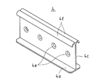
図3は、行列連結金具4を示す斜視図である。また、図4(a)、(b)、(c)は、行列連結金具4を示す側面図、平面図、及び正面図である。
FIG. 3 is a perspective view showing the
図3及び図4に示すように行列連結金具4は、底板4aと、天板4bと、底板4a及び天板4bを接続する立設板4cとを有している。立設板4cは、底板4aの仮想中心線上に接続されて、底板4aを2分し、また天板4bの仮想中心線上に接続されて、天板4bを2分する。この行列連結金具4の両側には、底板4a、天板4b、及び立設板4cで囲まれた係合凹部4dがそれぞれ形成され、これらの係合凹部4dが相反するそれぞれの外側方向に向く。また、立設板4cには、4つの穿孔4eが形成されている。
As shown in FIGS. 3 and 4, the
図5は、行間連結金具5を示す斜視図である。また、図6(a)、(b)、(c)は、行間連結金具5を示す側面図、平面図、及び正面図である。 FIG. 5 is a perspective view showing the inter-row connection fitting 5. FIGS. 6A, 6 </ b> B, and 6 </ b> C are a side view, a plan view, and a front view showing the inter-row connection fitting 5.
図5及び図6に示すように行間連結金具5は、立設板5aと、立設板5aの下辺で一方に折り曲げられた底板5bと、立設板5aの下辺で他方に折り曲げられた台板5cと、立設板5aの上辺で一方(底板5bと同じ側)に折り曲げられた第1留め部5dと、立設板5aの上辺で他方(台板5cと同じ側)に折り曲げられた2つの第2留め部5eとを有している。
As shown in FIGS. 5 and 6, the inter-row connection fitting 5 includes a standing
底板5bは、その両側を垂直に折り曲げてなる各搭載部5fを有している。また、底板5bには、穿孔5gが形成されている。各搭載部5fは、立設板5aから離間している。
The
台板5cは、3回折り曲げられ(上側、外側、下側に順次折り曲げられ)、台座部5hを形成している。台座部5hは、立設板5aから離間している。尚、台板5cには、底板5b及び各搭載部5fを切り起こしてなる開口部5iが形成されている。
The
第1留め部5dは、2つの第2留め部5eの中央に位置する。第1留め部5dは、立設板5aに対して直角に折り曲げられた押え部5jと、この押え部5jの先端側を斜め上方に折り曲げてなる呼込み部5kとを有している。また、第2留め部5eは、立設板5aに対して直角に折り曲げられている。
The
このような行間連結金具5の一方の側には、第1留め部5d及び各搭載部5fからなる係合部5mが形成され、他方の側には、第2留め部5e及び台座部5hからなる係合部5nが形成され、これらの係合部5m、5nが相反するそれぞれの外側方向に向く。
On one side of the inter-row connection fitting 5 is formed an
図7は、固定金具6を示す斜視図である。また、図8(a)、(b)、(c)は、固定金具6を示す側面図、平面図、及び正面図である。
FIG. 7 is a perspective view showing the fixing
図7及び図8に示すように固定金具6は、長矩形の主板6aと、主板6aの両辺で上方に折り曲げられた各側壁6bと、各側壁6bの上辺で内側に折り曲げられた各天板6cと、各天板6cの内側辺で下方に折り曲げられた各ガイド壁6dとを有している。各ガイド壁6d間に隙間が形成され、この隙間がスリット6eとなっている。また、各側板6bの一端部近傍には、それぞれのストッパー6fが形成されている。
As shown in FIGS. 7 and 8, the
図9は、行間連結金具5を固定金具6に取付けるための取付け金具11を示す斜視図である。図9に示すように取付け金具11は、その主板11aにネジ孔11bを形成し、主板11aの両辺を上側に折り曲げてT字型の各支持片11cを形成し、また主板11aの両側を3回折り曲げて(下側、外側、上側に順次折り曲げて)、各摺動部11dを形成したものである。
FIG. 9 is a perspective view showing an attachment fitting 11 for attaching the inter-row connection fitting 5 to the
このような行列連結金具4、行間連結金具5、固定金具6、及び取付け金具11のいずれも、例えば鋼板を打ち抜き、切断、折り曲げ加工して、メッキ処理を施したものである。また、行列連結金具4については、アルミの打ち抜き加工により形成したものであっても構わない。
All of the
ここで、先に述べたように固定金具6は、適宜の方法もしくは構造により屋根に固定される。このとき、固定金具6のスリット6eが図1の水流れ方向Cに沿うように、また固定金具6のストッパー6fが水流れ方向下側に位置するように、固定金具6の向きを設定する。そして、固定金具6に取付け金具11を取付け、更に行間連結金具5を固定金具6に固定する。
Here, as described above, the fixing
図10は、行間連結金具5、固定金具6、及び取付け金具11を示す分解斜視図である。また、図11は、行間連結金具5、固定金具6、及び取付け金具11の固定構造を示す断面図である。
FIG. 10 is an exploded perspective view showing the inter-row connecting
図10に示すように取付け金具11の各支持片11cを固定金具6のスリット6eに差し込んで、各支持片11cのT字型の頭部を各天板6cに引っ掛け、取付け金具11の各摺動部11dを固定金具6の両側の側壁6bとガイド壁6d間に挿入して、取付け金具11を固定金具6に取付ける。これにより、取付け金具11が固定金具6のスリット6eに沿って移動自在に支持される。また、固定金具6のストッパー6fにより取付け金具11の水流れ方向下側への脱落が防止される。
As shown in FIG. 10, each
この後、図11に示すように固定金具6の各天板6c上に突出した取付け金具11の各支持片11cの頭部間に行間連結金具5の底板5bを挟み込んで、行間連結金具5の底板5bを固定金具6の各天板6c上に載せ、行間連結金具5の底板5bの穿孔5gを取付け金具11の主板11aのネジ孔11bに重ね合わせ、ボルト12を行間連結金具5の穿孔5gを介して取付け金具11のネジ孔11bにねじ込んで、行間連結金具5を固定金具6に仮止めする。この仮止めの状態で行間連結金具5を列方向Bに移動させて位置決めし、この後にボルト12を締め付けて、行間連結金具5を固定金具6に固定する。
After that, as shown in FIG. 11, the
例えば、図1に示すような1行目(水流れ方向Cの最も下側の行)の各太陽電池モジュール2を直線状に配列するべく、最も下側の各行間連結金具5をそれぞれ列方向Bに適宜に移動させて、各行間連結金具5を行方向Aの直線に沿うように位置決めし、この後にボルト12を締め付けて、各行間連結金具5を固定金具6に固定する。
For example, in order to arrange the
こうして固定された行間連結金具5により列方向Bに並ぶ各太陽電池モジュール2の辺が連結接続される。
The sides of the
図11に示すように行間連結金具5は、列方向Bに並ぶ各太陽電池モジュール2の間に挟まれる。あるいは、1行目の各太陽電池モジュール2の一辺(水流れ方向下側の一辺)に接する。
As shown in FIG. 11, the inter-row connection fitting 5 is sandwiched between the
行間連結金具5両側の各太陽電池モジュール2のうちの水流れ方向上側(及び1行目)にある太陽電池モジュール2については、その枠部材8が行間連結金具5の各搭載部5fに載せられる。そして、枠部材8が行間連結金具5の第1留め部5dの押え部5jの下側に押し込められて、第1留め部5dの押え部5jにより枠部材8の上面が押えられ、枠部材8が行間連結金具5の各搭載部5fと第1留め部5dの押え部5j間に挟みこまれて固定される。また、枠部材8の端面が行間連結金具5の立設板5aに当接される。すなわち、水流れ方向上側(及び1行目)にある太陽電池モジュール2の枠部材8が行間連結金具5の係合部5m(図5(a)、(b)、図6(b)を参照)に係合する。
For the
例えば、二点鎖線で示すように太陽電池モジュール2を傾斜させて、枠部材8を行間連結金具5の各搭載部5fに載せてスライドさせ、枠部材8の下側角を行間連結金具5の各搭載部5fと立設板5a間の空きスペースに移動させると共に、枠部材8を第1留め部5dの呼込み部5kから押え部5jへと挿入して押し込み、引き続いて太陽電池モジュール2を水平に降ろす。これにより、枠部材8が各搭載部5fと第1留め部5dの押え部5j間に挟みこまれて固定され、枠部材8の端面が立設板5aに当接する。
For example, as shown by a two-dot chain line, the
第1留め部5dの先端側に斜め上方に折り曲げられた呼込み部5k形成していることから、傾斜した太陽電池モジュール2の枠部材8を第1留め部5dの呼込み部5kの下側に容易に入れることができ、引き続いて枠部材8を第1留め部5dの呼込み部6kから押え部5jへと容易に挿入して押し込むことができる。
Since the
また、行間連結金具5の各搭載部5fと立設板5a間を離間させていることから、第1留め部5dの下方が空き、枠部材8を行間連結金具5の各搭載部5fに載せてスライドさせると、傾斜した太陽電池モジュール2の枠部材8の下側角が各搭載部5fと立設板5a間に落ち込んで、枠部材8の上面を各第1留め部5dの押え部5jまで容易に押し込むことができる。
In addition, since each mounting
尚、二点鎖線で示すように太陽電池モジュール2を傾斜させず、太陽電池モジュール2の枠部材8を行間連結金具5の各搭載部5fに載せて水平に支持したまま、枠部材8を行間連結金具5の第1留め部5dの押え部5jの下側に押し込んでも構わない。
The
また、図11に示すように行間連結金具5両側の各太陽電池モジュール2のうちの水流れ方向下側にある太陽電池モジュール2については、その枠部材8が行間連結金具5の台座部5hに載せられる。そして、枠部材8が行間連結金具5の第2留め部5eの下側に押し込められて、第2留め部5eにより枠部材8の上面が押えられ、枠部材8が行間連結金具5の台座部5hと第2留め部5e間に挟みこまれて固定される。また、枠部材8の端面が行間連結金具5の立設板5aに当接される。すなわち、水流れ方向下側にある太陽電池モジュール2の枠部材8が行間連結金具5の係合部5n(図5(a)、(b)、図6(b)を参照)に係合する。
Further, as shown in FIG. 11, the
例えば、二点鎖線で示すように太陽電池モジュール2の枠部材8を行間連結金具5の台座部5hに載せてから、行間連結金具5を太陽電池モジュール2の枠部材8に接近するように水平方向に移動させて、枠部材8を行間連結金具5の台座部5hと第2留め部5e間に挿入して押し込む。これにより、枠部材8が台座部5hと第2留め部5e間に挟みこまれて固定され、枠部材8の端面が立設板5aに当接する。
For example, as shown by a two-dot chain line, the
従って、水流れ方向上側にある太陽電池モジュール2の枠部材8が行間連結金具5の一方の係合部5mに係合し、水流れ方向下側にある太陽電池モジュール2の枠部材8が行間連結金具5の他方の係合部5nに係合し、列方向Bに並ぶ各太陽電池モジュール2の枠部材8が行間連結金具5を介して連結接続される。
Accordingly, the
次に、行列連結金具4は、各太陽電池モジュール2の角近傍を連結接続するために用いられる。図12は、行列連結金具4による太陽電池モジュール2の枠部材8の連結構造を示す斜視図である。また、図13は、その連結構造を示す断面図である。
Next, the
図12、図13に示すように行列連結金具4両側の各太陽電池モジュール2のうちの水流れ方向下側(及び1行目)にある太陽電池モジュール2については、その枠部材8が、行列連結金具4の一方の係合凹部4d(図3、図4(b)を参照)に嵌合されて、行列連結金具4の底板4aと天板4b間に挟みこまれる。また、行方向Aに並ぶ2枚の太陽電池モジュール2の枠部材8の端部が、行列連結金具4の一方の係合凹部4dに共に嵌合される。そして、ネジ13が2本ずつ、行列連結金具4の各穿孔4eを介して2枚の太陽電池モジュール2の枠部材8にそれぞれねじ込まれて、行列連結金具4が2枚の太陽電池モジュール2の枠部材8に固定される。すなわち、水流れ方向下側(及び1行目)にあって行方向Aに並ぶ2枚の太陽電池モジュール2の枠部材8が行列連結金具4の一方の係合凹部4dに係合してネジ止めされる。
As shown in FIGS. 12 and 13, for the
また、行列連結金具4両側の各太陽電池モジュール2のうちの水流れ方向上側にある太陽電池モジュール2については、その枠部材8が、行列連結金具4の他方の係合凹部4dに嵌合されて、行列連結金具4の底板4aと天板4b間に挟みこまれる。また、行方向Aに並ぶ2枚の太陽電池モジュール2の枠部材8の端部が、行列連結金具4の他方の係合凹部4dに共に嵌合される。すなわち、水流れ方向上側にあって行方向Aに並ぶ2枚の太陽電池モジュール2の枠部材8が行列連結金具4の一方の係合凹部4dに係合する。
In addition, for the
従って、水流れ方向下側(及び1行目)にあって行方向Aに並ぶ2枚の太陽電池モジュール2の枠部材8が行列連結金具4の一方の係合凹部4dに係合してネジ止めされ、水流れ方向上側にあって行方向Aに並ぶ2枚の太陽電池モジュール2の枠部材8が行列連結金具4の他方の係合凹部4dに係合し、2行2列に並ぶ4枚の太陽電池モジュール2が行列連結具4を介して連結接続される。
Accordingly, the
ここで、図1に示すように4枚の太陽電池モジュール2の角部が集合するようないずれの箇所でも、4枚の太陽電池モジュール2の角部近傍が行列連結金具4で連結接続され、また列方向Bに並ぶ各太陽電池モジュール2の辺が隣り合うようないずれの箇所でも、各太陽電池モジュール2の辺が行間連結金具5で連結接続されているので、行列方向に並べられた各太陽電池モジュール2全てを一体的に強固に支持することができる。また、各行間連結金具5をそれぞれの固定金具6を介して屋根に接続固定しているので、各太陽電池モジュール2を屋根上に支持することができる。
Here, as shown in FIG. 1, the corner portions of the four
次に、本実施形態の太陽電池モジュール支持構造を用いて、太陽電池モジュール2を屋根上に取付けるための施工手順を説明する。
Next, a construction procedure for mounting the
まず、図1に示すように屋根上に複数の固定金具6を固定する。各固定金具6は、これらの固定金具6が後に行列方向に並べられる各太陽電池モジュール2の行方向Aの枠部材8と交差するようなそれぞれの位置に配置される。
First, as shown in FIG. 1, a plurality of fixing
このとき、最初の1番目に設置される太陽電池モジュール2については、相互に対向する行方向Aの2本の枠部材8と交差するような3つ以上の箇所に、それぞれの固定金具6を固定配置する。ここでは、1行1列目の太陽電池モジュール2が最初の1番目に設置されるものとする。
At this time, with respect to the first
また、2番目以降に設置される太陽電池モジュール2については、相互に対向する行方向Aの2本の枠部材8の中央付近と交差するようなそれぞれの箇所(2箇所)に、それぞれの固定金具6を固定配置する。
Moreover, about the
更に、固定金具6のスリット6eが図1の列方向Bに沿うように、固定金具6の向きを設定する。また、屋根に対する固定金具6の固定は、如何なる方法もしくは構造によってなされてもよい。
Further, the orientation of the fixing
引き続いて、各固定金具6にそれぞれの取付け金具11を取付け、各固定金具6上にそれぞれの行間連結金具5を載せ、各ボルト12をそれぞれの行間連結金具5の穿孔5gを通じてそれぞれの取付け金具11のネジ孔11bにねじ込んで、各固定金具6上にそれぞれの行間連結金具5を仮止めする。
Subsequently, each mounting
そして、水流れ方向Cの最も下側の各行間連結金具5をそれぞれ列方向Bに適宜に移動させて、これらの行間連結金具5を行方向Aの直線に沿うように位置決めし、それぞれのボルト12を締め付けて、これらの行間連結金具5を固定金具6に固定する。
And each row | line | column connection metal fitting 5 of the lowermost side of the water flow direction C is each moved to the column direction B suitably, these line
次に、最初の1番目の太陽電池モジュール2を1行1列目の位置に配置する。そして、図14(a)に示すように太陽電池モジュール2の枠部材8を水流れ方向Cの最も下側の行間連結金具5の各搭載部5fと下側から2番目の行間連結金具5の台座部5hに載せる。このとき、下側から2番目の行間連結金具5を固定金具6上で列方向Bに移動させて、行間連結金具5の位置調節を行ってもよい。
Next, the first first
更に、図14(b)に示すように太陽電池モジュール2の水流れ方向上側一辺を持ち上げ、図14(c)に示すように太陽電池モジュール2の枠部材8をスライドさせて行間連結金具5の第1留め部5dの呼込み部5kから押え部5jへと挿入して押し込む。
Further, as shown in FIG. 14 (b), the upper side in the water flow direction of the
引き続いて、図14(d)に示すように太陽電池モジュール2の水流れ方向上側一辺を降ろして、太陽電池モジュール2の水流れ方向上側一辺を下側から2番目の行間連結金具5の台座部5hに載せる。このとき、太陽電池モジュール2の水流れ方向下側の枠部材8が行間連結金具5の係合部5m(図5(a)、(b)、図6(b)を参照)に係合する。
Subsequently, as shown in FIG. 14 (d), the upper side in the water flow direction of the
そして、下側から2番目の行間連結金具5を固定金具6上で水流れ方向Cに移動させて、太陽電池モジュール2の水流れ方向上側の枠部材8を行間連結金具5の台座部5hと第2留め部5e間に挿入して押し込む。これにより、太陽電池モジュール2の水流れ方向上側の枠部材8が行間連結金具5の係合部5n(図5(a)、(b)、図6(b)を参照)に係合する。更に、下側から2番目の行間連結金具5のボルト12を締め付けて、この行間連結金具5を固定する。
Then, the second row connection fitting 5 from the lower side is moved in the water flow direction C on the
先に述べたように1行1列目の太陽電池モジュール2については、相互に対向する行方向Aの2本の枠部材8と交差する3つ以上の箇所にそれぞれの固定金具6を固定配置していることから、これらの箇所でそれぞれの行間連結金具5に太陽電池モジュール2の枠部材8が係合する。このため、1行1列目の太陽電池モジュール2がぐらつくことなく安定的に支持される。
As described above, with respect to the
尚、1行1列目の太陽電池モジュール2については、3つ以上の固定金具6のうちの1つを仮固定用のスペーサに置き換えて、太陽電池モジュール2をぐらつくことなく安定的に支持しておき、後で述べるような1行1列目と2列目の各太陽電池モジュール2を行列連結金具4を介して連結した後に、仮固定用のスペーサを外しても構わない。
For the
次に、2番目の太陽電池モジュール2を1行2列目の位置に配置し、この太陽電池モジュール2を図14(a)〜図14(d)と同様の手順で各行間連結金具5に係合させる。
Next, the second
また、1行1列目と2列目の各太陽電池モジュール2の水流れ方向下側の枠部材8が行列連結金具4の係合凹部4dに共に嵌合されてネジ止めされ、各太陽電池モジュール2の水流れ方向上側の枠部材8も別の行列連結金具4の係合凹部4dに共に嵌合されてネジ止めされ、各太陽電池モジュール2が2つの行列連結金具4を介して連結される。
Further, the
2番目以降に設置される太陽電池モジュール2については、相互に対向する行方向Aの2本の枠部材8の中央付近と交差するようなそれぞれの箇所(2箇所)にそれぞれの固定金具6を固定配置していることから、2箇所の行間連結金具5に太陽電池モジュール2の枠部材8が係合する。このため、太陽電池モジュール2がぐらつくことになる。ところが、1行1列目の太陽電池モジュール2がぐらつくことなく安定的に支持されているので、1行1列目と2列目の各太陽電池モジュール2の枠部材8が行列連結金具4で連結接続されると、2列目の太陽電池モジュール2もぐらつくことなく安定的に支持される。また、1行1列目の太陽電池モジュール2がぐらつくことなく安定的に支持されているので、行列連結金具4の取付け作業が容易となる。
About the
仮に、1行1列目の太陽電池モジュール2がぐらついていたならば、1行1列目と2列目の各太陽電池モジュール2の枠部材8を行列連結金具4に共に係合させる作業が困難になる。
If the
次に、1行3列目以降の太陽電池モジュール2についても、図14(a)〜図14(d)と同様の手順で各行間連結金具5に係合させる。また、隣り合う各太陽電池モジュール2の水流れ方向下側の枠部材8を行列連結金具4の係合凹部4dに共に嵌合させてネジ止めし、隣り合う各太陽電池モジュール2の水流れ方向上側の枠部材8も別の行列連結金具4の係合凹部4dに共に嵌合させてネジ止めし、隣り合う各太陽電池モジュール2を2つの行列連結金具4を介して連結する。
Next, the
また、1行3列目以降の太陽電池モジュール2についても、前の列の太陽電池モジュール2がぐらつくことなく安定的に支持されていることから、隣り合う各太陽電池モジュール2の枠部材8を行列連結金具4に共に係合させる作業が容易となり、1行目の全ての太陽電池モジュール2がぐらつくことなく安定的に支持される。
In addition, the
次に、2行各列の各太陽電池モジュール2についても、図14(a)〜図14(d)と同様の手順で各行間連結金具5に係合させる。あるいは、太陽電池モジュール2を傾斜させず、太陽電池モジュール2の枠部材8を行間連結金具5の各搭載部5fに載せて水平に支持したまま、枠部材8を行間連結金具5の第1留め部5dの押え部5jの下側に押し込んで、枠部材8を行間連結金具5に係合させる。同時に、隣り合う各太陽電池モジュール2の枠部材8を各行列連結金具4に共に係合させる。
Next, the
このとき、隣り合う各太陽電池モジュール2の水流れ方向下側の枠部材8は、1行目の各太陽電池モジュール2の水流れ方向上側の枠部材8にネジ止めされた行列連結金具4に係合される。このため、2行目の各太陽電池モジュール2の水流れ方向下側の枠部材8に対する行列連結金具4のネジ止めが行われない。また、2行目の各太陽電池モジュール2の水流れ方向上側の枠部材8に対しては行列連結金具4のネジ止めが行われる。
At this time, the
次に、3行目以降の各太陽電池モジュール2についても、同様の手順で、各行間連結金具5及び各行列連結金具4に係合される。
Next, the
尚、図1に示すように各行の両端の行列連結金具4は、太陽電池モジュール2から食み出さないように配置する。
As shown in FIG. 1, the
こうして本実施形態の太陽電池モジュール支持構造を用いた太陽光発電システムが構築される。この太陽光発電システムにおいては、各太陽電池モジュール2の枠部材8の間に行列連結金具4及び行間連結金具5が挟み込まれている。
Thus, a solar power generation system using the solar cell module support structure of the present embodiment is constructed. In this solar power generation system, the
行間連結金具5の各係合部5m、5nには、前の行における太陽電池モジュール2の水流れ方向上側の枠部材8と次の行における太陽電池モジュール2の水流れ方向下側の枠部材8とがそれぞれ係合する。従って、列方向Bに並ぶ2枚の太陽電池モジュール2の枠部材8が行間連結金具5で連結接続される。
The engaging
また、行列連結金具4の各係合凹部4dには、前の行に並ぶ2枚の太陽電池モジュール2の水流れ方向上側の枠部材8と次の行に並ぶ2枚の太陽電池モジュール2の水流れ方向下側の枠部材8とがそれぞれ係合する。従って、2行2列に並ぶ4枚の太陽電池モジュール2の枠部材8が行列連結金具4で連結接続される。
Further, in each
このような行列連結金具4及び行間連結金具5による連結は、各太陽電池モジュール2のいずれの間でもなされ、太陽光発電システムの各太陽電池モジュール2全体が一体的に支持される。そして、各行間連結金具5をそれぞれの固定金具6を介して屋根2に固定している。このような構成では、従来の架台の桟等を必要とせず、部品点数の無駄な増加を抑えることができ、太陽光発電に寄与しない無駄なスペースを最小限に抑えることができる。
Such connection by the
また、複数の太陽電池モジュール2を1枚ずつ屋根2に固定するのではなく、複数の太陽電池モジュール2を一体化して、1枚目を除く他の各太陽電池モジュール2の2箇所を固定するだけなので、作業効率がよい。
Further, instead of fixing the plurality of
更に、1枚目を除く他の各太陽電池モジュール2の2つの固定箇所は、相互に対向する行方向Aの2本の枠部材8の中央付近であるため、これらの太陽電池モジュール2のたわみ等の変形を効果的に抑えることができ、これらの太陽電池モジュール2の荷重をバランスよく支持することができる。
Further, since the two fixed portions of the other
また、ネジ13を2本ずつ、行列連結金具4の各穿孔4eを介して2枚の太陽電池モジュール2の枠部材8にそれぞれねじ込んで、行列連結金具4を2枚の太陽電池モジュール2の枠部材8に固定しているので、2枚の太陽電池モジュール2の枠部材8が行列連結金具4を介して電気的に接続され、1行の各太陽電池モジュール2の枠部材8が導通する。このため、各太陽電池モジュール2の接地が容易になる。
Further, two
更に、図1の箇所Pで示すように行の端に配置された行列連結金具4を、列方向Bに並ぶ2枚の太陽電池モジュール2の外側辺に係合させてネジ止めすれば、2行の太陽電池モジュール2の枠部材8が導通し、行列方向A、Bに配列された全ての太陽電池モジュール2の枠部材8が導通し、各太陽電池モジュール2の接地がより容易になる。
Furthermore, as shown by the point P in FIG. 1, the matrix connection fitting 4 arranged at the end of the row is engaged with the outer side of the two
以上、添付図面を参照しながら本発明の好適な実施形態について説明したが、本発明は係る例に限定されないことは言うまでもない。当業者であれば、特許請求の範囲に記載された範疇内において、各種の変更例または修正例に想到し得ることは明らかであり、それらについても当然に本発明の技術的範囲に属するものと解される。 As mentioned above, although preferred embodiment of this invention was described referring an accompanying drawing, it cannot be overemphasized that this invention is not limited to the example which concerns. It will be apparent to those skilled in the art that various changes and modifications can be made within the scope of the claims, and these are naturally within the technical scope of the present invention. It is understood.
例えば、図15に示すように行列連結金具4の立設板4cの上辺に、該立設板4cの両側に突出して下方に曲がるそれぞれの鈎状突起部4fを設け、立設板4cの両側で、太陽電池モジュール2の枠部材8を底板4aと鈎状突起部4f間に挟み込んで、鈎状突起部4fの先端を太陽電池モジュール2の枠部材8に食い込ませて導通させてもよい。
For example, as shown in FIG. 15, on the upper side of the upright plate 4c of the
あるいは、図16に示すように行間連結金具5の立設板5aの上辺に、該立設板5aの両側に突出して下方に曲がるそれぞれの鈎状突起部5pを設け、立設板5aの片側で、太陽電池モジュール2の枠部材8を各搭載部5fと鈎状突起部5p間に挟み込んで、鈎状突起部5pの先端を太陽電池モジュール2の枠部材8に食い込ませて導通させ、また立設板5aの他の片側で、太陽電池モジュール2の枠部材8を台座部5hと鈎状突起部5p間に挟み込んで、鈎状突起部5pの先端を太陽電池モジュール2の枠部材8に食い込ませて導通させてもよい。
Alternatively, as shown in FIG. 16, on the upper side of the
更に、図17に示すような断面形状の枠部材8を太陽電池モジュール2に適用し、この枠部材8の嵌合溝8aに、行列連結金具4の鈎状突起部4fや行間連結金具5の鈎状突起部5pを引っ掛けて食い込ませても構わない。
Furthermore, a
図15、図16に示すような行列連結金具4及び行間連結金具5を用いることにより、太陽光発電システムの各太陽電池モジュール2の枠部材8を相互に導通させることができ、各太陽電池モジュール2の接地配線が容易になる。
By using the
また、本実施形態では、行方向Aを水流れ方向Cと直行する方向とし、列方向Bを水流れ方向Cに沿う方向としているが、これとは逆に、行方向Aを水流れ方向Cに沿う方向とし、列方向Bを水流れ方向Cと直交する方向としてもよい。 In the present embodiment, the row direction A is a direction perpendicular to the water flow direction C, and the column direction B is a direction along the water flow direction C. Conversely, the row direction A is the water flow direction C. The row direction B may be a direction perpendicular to the water flow direction C.
1 太陽光発電システム
2 太陽電池モジュール
4 行列連結金具
4d 係合凹部
5 行間連結金具
5m、5n 係合部
6 固定金具
7 太陽電池パネル
8 枠部材
11 取付け金具
12 ボルト
13 ネジ
DESCRIPTION OF
Claims (4)
列方向に並ぶ2枚の太陽電池モジュールの枠部材の間に配置されて、前記列方向に並ぶ2枚の太陽電池モジュールの枠部材に係合して、前記列方向に並ぶ2枚の太陽電池モジュールを連結することができるように、相反するそれぞれの外側方向に向く2つの係合部が形成された連結具と、
前記連結具を支持して土台に固定するものであって、前記連結具の支持位置が列方向に移動可能な構造が設けられた固定具とを備え、
前記連結具及び前記固定具が行方向及び列方向に複数配列されたことを特徴とする太陽電池モジュール支持構造。 A solar cell module support structure that supports a plurality of solar cell modules arranged in a matrix direction,
Two solar cells arranged between the frame members of the two solar cell modules arranged in the column direction, engaged with the frame members of the two solar cell modules arranged in the column direction, and arranged in the column direction A connector formed with two engaging portions facing in opposite outer directions so that the modules can be connected;
A fixing tool provided with a structure for supporting the connecting tool and fixing it to a base, wherein a support position of the connecting tool is movable in a row direction;
A solar cell module support structure, wherein a plurality of the coupling tools and the fixing tools are arranged in a row direction and a column direction.
前記連結具は、該連結具の係合部に係合した太陽電池モジュールの枠部材に食い込む突起を有することを特徴とする太陽電池モジュール支持構造。 The solar cell module support structure according to claim 1,
The said connecting tool has a protrusion which bites into the frame member of the solar cell module engaged with the engaging part of this connecting tool, The solar cell module support structure characterized by the above-mentioned.
前記固定具を行方向及び列方向に複数配列されるように前記土台に固定し、
前記土台に固定された前記固定具に、支持位置が列方向に移動可能なように、前記連結具を仮止めし、
前記連結具の複数が行方向で直線に沿うように、前記連結具を前記固定具に固定し、
前記固定具に固定された連結具の一方の係合部に、太陽電池モジュールの枠部材を係合し、
前記連結具の一方の係合部に係合された前記太陽電モジュールの枠部材の反対側で仮止めされていた連結具の支持位置を列方向に移動させ、この移動させた連結具の一方の係合部に前記太陽電池モジュールの枠部材の反対側を係合し、
前記太陽電池モジュールの枠部材の反対側に係合された連結具を前記固定具に固定することを特徴とする太陽電池モジュールの設置方法。 A plurality of solar cell modules are arranged side by side in a matrix direction using a coupling tool in which two engaging portions facing each other in opposite directions are formed, and a fixture that supports the coupling tool and fixes it to the base. A solar cell module installation method,
Fixing the fixture to the base so that a plurality of the fixtures are arranged in a row direction and a column direction;
Temporarily fix the connector so that the support position can be moved in the row direction to the fixture fixed to the base,
Fixing the connector to the fixture such that a plurality of the connectors are along a straight line in the row direction;
Engage the frame member of the solar cell module with one engaging portion of the connector fixed to the fixture,
The support position of the connection tool temporarily fixed on the opposite side of the frame member of the solar power module engaged with one engagement portion of the connection tool is moved in the row direction, and one of the moved connection tools Engaging the opposite side of the frame member of the solar cell module with the engaging portion of
An installation method for a solar cell module, comprising: fixing a connector engaged with the opposite side of the frame member of the solar cell module to the fixture.
Priority Applications (1)
| Application Number | Priority Date | Filing Date | Title |
|---|---|---|---|
| JP2011156843A JP5388311B2 (en) | 2011-07-15 | 2011-07-15 | Solar cell module support structure, solar power generation system using the support structure, and solar cell module installation method |
Applications Claiming Priority (1)
| Application Number | Priority Date | Filing Date | Title |
|---|---|---|---|
| JP2011156843A JP5388311B2 (en) | 2011-07-15 | 2011-07-15 | Solar cell module support structure, solar power generation system using the support structure, and solar cell module installation method |
Related Parent Applications (1)
| Application Number | Title | Priority Date | Filing Date |
|---|---|---|---|
| JP2010091686A Division JP4879336B2 (en) | 2010-04-12 | 2010-04-12 | Solar cell module support structure, method of constructing the support structure, and photovoltaic power generation system using the support structure |
Publications (2)
| Publication Number | Publication Date |
|---|---|
| JP2011220110A JP2011220110A (en) | 2011-11-04 |
| JP5388311B2 true JP5388311B2 (en) | 2014-01-15 |
Family
ID=45037413
Family Applications (1)
| Application Number | Title | Priority Date | Filing Date |
|---|---|---|---|
| JP2011156843A Expired - Fee Related JP5388311B2 (en) | 2011-07-15 | 2011-07-15 | Solar cell module support structure, solar power generation system using the support structure, and solar cell module installation method |
Country Status (1)
| Country | Link |
|---|---|
| JP (1) | JP5388311B2 (en) |
Families Citing this family (5)
| Publication number | Priority date | Publication date | Assignee | Title |
|---|---|---|---|---|
| JP5622709B2 (en) * | 2011-12-02 | 2014-11-12 | 不二高圧コンクリート株式会社 | Supporting frame structure for photovoltaic panel frame |
| JP6029228B2 (en) * | 2012-04-06 | 2016-11-24 | 積水化学工業株式会社 | Solar cell module panel mounting jig, mounting structure, and mounting method |
| JP5891109B2 (en) * | 2012-05-30 | 2016-03-22 | 株式会社屋根技術研究所 | Solar cell module fixing structure and solar cell module fixing method |
| JP6334941B2 (en) * | 2014-02-13 | 2018-05-30 | 奥地建産株式会社 | Structure and method for supporting and fixing a planar article on a roof |
| JP6558632B2 (en) * | 2015-07-22 | 2019-08-14 | パナソニックIpマネジメント株式会社 | Solar power plant |
Family Cites Families (6)
| Publication number | Priority date | Publication date | Assignee | Title |
|---|---|---|---|---|
| JPH0718795A (en) * | 1993-07-01 | 1995-01-20 | Natl House Ind Co Ltd | Fitting structure of solar cell panel |
| JP2001271468A (en) * | 2000-03-28 | 2001-10-05 | Matsushita Electric Ind Co Ltd | Fitting structure of solar cell module |
| JP3907668B2 (en) * | 2005-04-07 | 2007-04-18 | シャープ株式会社 | Mounting structure of solar cell module |
| JP4844466B2 (en) * | 2007-04-27 | 2011-12-28 | パナソニック電工株式会社 | Mounting structure for roof mounting fixtures |
| JP4365450B1 (en) * | 2009-05-01 | 2009-11-18 | 株式会社屋根技術研究所 | Solar cell module fixing structure, solar cell module frame and fixing member |
| JP4365449B2 (en) * | 2009-05-01 | 2009-11-18 | 株式会社屋根技術研究所 | Solar cell module construction method |
-
2011
- 2011-07-15 JP JP2011156843A patent/JP5388311B2/en not_active Expired - Fee Related
Also Published As
| Publication number | Publication date |
|---|---|
| JP2011220110A (en) | 2011-11-04 |
Similar Documents
| Publication | Publication Date | Title |
|---|---|---|
| JP4879336B2 (en) | Solar cell module support structure, method of constructing the support structure, and photovoltaic power generation system using the support structure | |
| JP4688951B1 (en) | Structure installation stand, structure installation support, and solar power generation system | |
| JP5388311B2 (en) | Solar cell module support structure, solar power generation system using the support structure, and solar cell module installation method | |
| JP5463331B2 (en) | Solar cell module support structure, method of constructing the support structure, and photovoltaic power generation system using the support structure | |
| JP2006291506A (en) | Mounting structure of solar cell module | |
| JP5388880B2 (en) | Solar cell module fixing structure, solar cell module mount, solar cell module construction method, and solar cell power generation system | |
| JP5213977B2 (en) | Solar cell module mount, construction method thereof, and solar power generation system including the same | |
| JP2002030773A (en) | Roof installation type solar energy generator | |
| JP5891109B2 (en) | Solar cell module fixing structure and solar cell module fixing method | |
| JP2003278333A (en) | Support fitting for mounting solar battery panel | |
| JP5965376B2 (en) | Solar cell module support structure and solar power generation system using the support structure | |
| JP5637762B2 (en) | Construction support structure construction method, structure support structure, and solar power generation system using the construction method or structure support structure | |
| JP6224389B2 (en) | Equipment installation materials and equipment installation roof | |
| JP6661320B2 (en) | Solar cell module installation structure, installation method, and solar power generation system using the installation structure | |
| JP5405631B2 (en) | Solar cell module installation structure, solar cell module installation method, and solar power generation system | |
| JP3934453B2 (en) | Roof structure with solar panel | |
| JP2008088689A (en) | Mounting structure of solar cell module | |
| JP6192453B2 (en) | Roof structure, solar cell module fixture, solar cell module mounting structure, and solar cell module mounting method | |
| JP6541023B2 (en) | Photovoltaic power generation device and fixing method of solar cell module | |
| JP7215931B2 (en) | photovoltaic device | |
| JP6021579B2 (en) | Solar cell module support structure and solar cell module installation method | |
| JP5829572B2 (en) | Rail fixing structure | |
| JP5923078B2 (en) | Solar cell module installation structure, solar cell module installation method, and solar power generation system | |
| JP2007186905A (en) | Solar cell module-integrated roofing | |
| JP5159925B2 (en) | Solar cell module installation structure, solar cell module installation method, and solar power generation system |
Legal Events
| Date | Code | Title | Description |
|---|---|---|---|
| A621 | Written request for application examination |
Free format text: JAPANESE INTERMEDIATE CODE: A621 Effective date: 20110826 |
|
| A977 | Report on retrieval |
Free format text: JAPANESE INTERMEDIATE CODE: A971007 Effective date: 20121213 |
|
| TRDD | Decision of grant or rejection written | ||
| A01 | Written decision to grant a patent or to grant a registration (utility model) |
Free format text: JAPANESE INTERMEDIATE CODE: A01 Effective date: 20131001 |
|
| A61 | First payment of annual fees (during grant procedure) |
Free format text: JAPANESE INTERMEDIATE CODE: A61 Effective date: 20131004 |
|
| R150 | Certificate of patent or registration of utility model |
Ref document number: 5388311 Country of ref document: JP Free format text: JAPANESE INTERMEDIATE CODE: R150 Free format text: JAPANESE INTERMEDIATE CODE: R150 |
|
| LAPS | Cancellation because of no payment of annual fees |