JP5891109B2 - Solar cell module fixing structure and solar cell module fixing method - Google Patents
Solar cell module fixing structure and solar cell module fixing method Download PDFInfo
- Publication number
- JP5891109B2 JP5891109B2 JP2012122693A JP2012122693A JP5891109B2 JP 5891109 B2 JP5891109 B2 JP 5891109B2 JP 2012122693 A JP2012122693 A JP 2012122693A JP 2012122693 A JP2012122693 A JP 2012122693A JP 5891109 B2 JP5891109 B2 JP 5891109B2
- Authority
- JP
- Japan
- Prior art keywords
- solar cell
- cell module
- fixing
- contact piece
- crosspiece
- Prior art date
- Legal status (The legal status is an assumption and is not a legal conclusion. Google has not performed a legal analysis and makes no representation as to the accuracy of the status listed.)
- Active
Links
Images


Classifications
-
- Y—GENERAL TAGGING OF NEW TECHNOLOGICAL DEVELOPMENTS; GENERAL TAGGING OF CROSS-SECTIONAL TECHNOLOGIES SPANNING OVER SEVERAL SECTIONS OF THE IPC; TECHNICAL SUBJECTS COVERED BY FORMER USPC CROSS-REFERENCE ART COLLECTIONS [XRACs] AND DIGESTS
- Y02—TECHNOLOGIES OR APPLICATIONS FOR MITIGATION OR ADAPTATION AGAINST CLIMATE CHANGE
- Y02B—CLIMATE CHANGE MITIGATION TECHNOLOGIES RELATED TO BUILDINGS, e.g. HOUSING, HOUSE APPLIANCES OR RELATED END-USER APPLICATIONS
- Y02B10/00—Integration of renewable energy sources in buildings
- Y02B10/10—Photovoltaic [PV]
-
- Y—GENERAL TAGGING OF NEW TECHNOLOGICAL DEVELOPMENTS; GENERAL TAGGING OF CROSS-SECTIONAL TECHNOLOGIES SPANNING OVER SEVERAL SECTIONS OF THE IPC; TECHNICAL SUBJECTS COVERED BY FORMER USPC CROSS-REFERENCE ART COLLECTIONS [XRACs] AND DIGESTS
- Y02—TECHNOLOGIES OR APPLICATIONS FOR MITIGATION OR ADAPTATION AGAINST CLIMATE CHANGE
- Y02E—REDUCTION OF GREENHOUSE GAS [GHG] EMISSIONS, RELATED TO ENERGY GENERATION, TRANSMISSION OR DISTRIBUTION
- Y02E10/00—Energy generation through renewable energy sources
- Y02E10/50—Photovoltaic [PV] energy
Landscapes
- Roof Covering Using Slabs Or Stiff Sheets (AREA)
- Photovoltaic Devices (AREA)
Description
本発明は、屋根材上に設置される太陽電池モジュールの固定構造及び固定方法に関するものである。 The present invention relates to a fixing structure and a fixing method for a solar cell module installed on a roof material.
屋根瓦やスレート等の屋根材の上に設置される太陽電池モジュールの取付架台として、屋根の傾斜方向(流れ方向)へ延びる複数の長尺の縦桟を所定の間隔で屋根材上に固定し、それらの縦桟の上に、屋根の傾斜方向に対して直角方向(横方向)へ延びる複数の長尺の横桟をボルトで固定することにより井桁状に形成したものが知られている。 As a mounting base for solar cell modules installed on roofing materials such as roof tiles and slate, a plurality of long vertical rails extending in the roof inclination direction (flow direction) are fixed on the roofing material at predetermined intervals. It is known that a plurality of long horizontal rails extending in a direction perpendicular to the inclination direction of the roof (lateral direction) are fixed on the vertical rails by bolts to form a cross beam.
ところが、上記の取付架台では、横桟に太陽電池モジュールの横方向の辺を載置させて太陽電池モジュールを固定するため、横桟を太陽電池モジュールの大きさに合せた間隔で精度よく縦桟に取付けなければならず、ひいては取付架台の設置に手間がかかり、作業コストが高くなるという問題があった。また、取付架台が縦桟及び横桟によって井桁状に形成されるため、多くの桟部材を必要とし部材コストが高くなるという問題もあった。 However, in the mounting frame described above, since the solar cell module is fixed by placing the side of the solar cell module in the horizontal direction on the horizontal beam, the vertical beam is accurately spaced at intervals corresponding to the size of the solar cell module. There is a problem that it takes time to install the mounting base and the work cost becomes high. Moreover, since the mounting frame is formed in a cross beam shape by the vertical beam and the horizontal beam, there is a problem that many beam members are required and the member cost is increased.
そこで、本願出願人は、太陽電池モジュールの設置に係るコストを低減させることが可能な太陽電池モジュールの固定構造を先に提案した(特許文献1)。図4及び図5に示すように、この固定構造100は、屋根材103上に複数取付けられる支持部材105と、その支持部材105の支持片104間に挿入されると共に複数の支持部材105によって支持される桟部材106と、複数の桟部材106上に載置された太陽電池モジュール101を桟部材106に固定する固定部材107とを備えるものである。
Therefore, the applicant of the present application has previously proposed a solar cell module fixing structure capable of reducing the cost associated with the installation of the solar cell module (Patent Document 1). As shown in FIGS. 4 and 5, this
さらに詳しく説明すると、桟部材106の上面には、締結部材111をスライド可能に保持する保持部112が設けられており、締結部材111に被締結部材113を締結することにより、固定部材107が桟部材106に固定される。これによれば、井桁状の取付架台を構成する必要がないため、部品点数が少なくなり部材コストを低減すると共に、取付けにかかる手間を簡略化することができる。
More specifically, a
上記の固定構造によると、複数の太陽電池モジュール101を固定するには、それらを桟部材106の上面に載置した上で、太陽電池モジュール101同士の間に位置する締結部材111に固定部材107を取付け、さらに締結部材111に被締結部材113を締結することになる。そして、これらの作業は、太陽電池モジュール101の上に乗って行われていた。しかしながら、太陽電池モジュール101上での作業は、滑りやすく、しかも太陽電池モジュール101が破損するおそれがあることから、慎重に作業する必要があり、作業性が悪くなっていた。また、太陽電池モジュール101同士の間に締結部材111及び被締結部材113が配置されるため、太陽電池モジュール101同士の隙間が大きくなり、屋根の面積に対する太陽電池モジュール101の面積の割合が少なくなるという問題があった。つまり、発電効率の点においても改善する余地があった。
According to the above fixing structure, in order to fix the plurality of
そこで、本発明は、上記の実状に鑑み、太陽電池モジュールの設置にかかる作業を一層容易なものとすると共に、太陽電池モジュール同士の隙間を極力小さくして発電効率を高めることが可能な太陽電池モジュールの固定構造及び固定方法を提供することを課題とするものである。 Therefore, in view of the above situation, the present invention makes it possible to further facilitate the work for installing the solar cell module and to reduce the gap between the solar cell modules as much as possible to increase the power generation efficiency. It is an object of the present invention to provide a module fixing structure and a fixing method.
上記の課題を解決するために、本発明にかかる太陽電池モジュールの固定構造は、
「屋根材上に配置される長尺の桟部材と、
該桟部材の上側に設置される太陽電池モジュールを前記桟部材に固定する固定手段と
を具備し、
前記桟部材は、前記固定手段を前記桟部材に締結するための締結部材を、長手方向へのみスライド可能に保持する保持部を上面に有し、
前記固定手段は、
太陽電池モジュールの上面に当接可能とされ、前記桟部材の前記長手方向と平行な方向へ延びた上側当接片、
該上側当接片の中央から下方へ延出した軸部、
該軸部の途中から前記桟部材の前記長手方向と平行な一方向へ前記上側当接片よりも長く延び、太陽電池モジュールの下面に当接可能な下側当接片、
及び、前記軸部の下端から前記下側当接片と平行な方向へ延び、前記下側当接片と前記桟部材との間に所定の空間を形成すると共に、前記桟部材上に載置され、前記締結部材または該締結部材に締結される被締結部材が挿入可能な第一開口を有する取着片、
を有する第一固定部材と、
該第一固定部材の前記軸部を挟んで前記下側当接片の反対側に配置され、前記下側当接片が当接する太陽電池モジュールとは異なる太陽電池モジュールと前記桟部材との間に挿入可能とされ、該太陽電池モジュールを、前記下側当接片が当接する太陽電池モジュールと同じ高さに載置する載置部、
及び、該載置部の下端から前記桟部材の前記長手方向と平行な方向へ延びると共に、前記取着片の下側に配置され、前記締結部材または前記被締結部材が挿入可能な第二開口を有する挟持片
を有し前記第一固定部材とは別部材とされた第二固定部材と
を備える」
ことを特徴とするものである。
In order to solve the above problems, a solar cell module fixing structure according to the present invention is:
`` Long bar members placed on the roofing material,
A fixing means for fixing the solar cell module installed on the upper side of the crosspiece member to the crosspiece member,
The cross member has a holding portion on the upper surface for holding a fastening member for fastening the fixing means to the cross member so as to be slidable only in the longitudinal direction,
The fixing means includes
An upper contact piece that is capable of contacting the upper surface of the solar cell module and extends in a direction parallel to the longitudinal direction of the crosspiece member;
A shaft portion extending downward from the center of the upper contact piece,
A lower contact piece that extends from the middle of the shaft portion in a direction parallel to the longitudinal direction of the crosspiece member in a direction longer than the upper contact piece and is capable of contacting the lower surface of the solar cell module;
And it extends in a direction parallel to the lower contact piece from the lower end of the shaft portion, forms a predetermined space between the lower contact piece and the crosspiece member, and is placed on the crosspiece member An attachment piece having a first opening into which the fastening member or a fastened member fastened to the fastening member can be inserted,
A first fixing member having
Between the solar cell module and the crosspiece member, which is disposed on the opposite side of the lower contact piece across the shaft portion of the first fixing member and different from the solar cell module with which the lower contact piece contacts. A mounting portion for mounting the solar cell module at the same height as the solar cell module with which the lower contact piece abuts,
And a second opening that extends from a lower end of the mounting portion in a direction parallel to the longitudinal direction of the crosspiece member and is disposed below the attachment piece and into which the fastening member or the fastening member can be inserted. And a second fixing member that is a separate member from the first fixing member.
It is characterized by this.
ここで、「桟部材」は、例えば、屋根材上に複数取付けられる支持部材によって支持されるようにしてもよい。また、「桟部材」は、長手方向に対して直角方向に所定の間隔で複数配置されるようにしてもよい。また、「締結部材及び被締結部材」としては、「ナット及びボルト」、または「ボルト及びナット」等の組合せを例示することができる。 Here, the “crosspiece member” may be supported by, for example, a plurality of support members attached on the roofing material. A plurality of “cross members” may be arranged at a predetermined interval in a direction perpendicular to the longitudinal direction. Examples of the “fastening member and fastened member” include “nuts and bolts” or “bolts and nuts”.
また、「載置部」は、太陽電池モジュールの他端側底面に当接してもよいが、太陽電池モジュールの枠体にフランジ部を有する場合には、フランジ部の下面に当接してもよい。また、「上側当接片」は、太陽電池モジュールの枠体(フランジ付きのものを含む)の上面に当接してもよい。 In addition, the “mounting portion” may abut against the bottom surface of the other end side of the solar cell module, but when the frame of the solar cell module has a flange portion, it may abut against the lower surface of the flange portion. . In addition, the “upper abutment piece” may abut on the upper surface of the frame (including the flanged one) of the solar cell module.
本発明によれば、太陽電池モジュールを桟部材に固定する固定手段は、互いに別部材である第一固定部材及び第二固定部材を備えている。第一固定部材は、軸部の下端から桟部材の長手方向と平行な方向へ延び桟部材上に載置可能な取着片を備えており、その取着片には締結部材または被締結部材が挿入可能な第一開口が穿設されている。一方、第二固定部材は、桟部材の長手方向と平行な方向へ延びる挟持片を備えており、その挟持片には取着片と同じように、締結部材または被締結部材が挿入可能な第二開口が穿設されている。このため、挟持片を取着片と桟部材との間に挟んだ状態で、桟部材に保持された締結部材と被締結部材とを挟持片の第二開口及び取着片の第一開口を通して締結すると、第一固定部材及び第二固定部材が共に桟部材に固定される。 According to the present invention, the fixing means for fixing the solar cell module to the crosspiece member includes the first fixing member and the second fixing member which are separate members. The first fixing member includes an attachment piece that extends from the lower end of the shaft portion in a direction parallel to the longitudinal direction of the crosspiece member and can be placed on the crosspiece member. The 1st opening which can insert is drilled. On the other hand, the second fixing member includes a sandwiching piece extending in a direction parallel to the longitudinal direction of the crosspiece member, and the fastening member or the fastened member can be inserted into the sandwiching piece in the same manner as the attachment piece. Two openings are drilled. For this reason, in a state where the sandwiching piece is sandwiched between the attachment piece and the crosspiece member, the fastening member and the fastened member held by the crosspiece member are passed through the second opening of the sandwiching piece and the first opening of the attachment piece. When fastened, both the first fixing member and the second fixing member are fixed to the crosspiece member.
また、第一固定部材は、軸部の上端に形成され桟部材の長手方向と平行な方向へ延びた上側当接片と、軸部の途中から桟部材の長手方向と平行な方向へ延びた下側当接片とを備えるため、上側当接片(詳しくは下側当接片と同じ方向に延出した部分)と下側当接片との間に太陽電池モジュールの一端側を挿入すると、太陽電池モジュールの一端側は上面が上側当接片に当接し、下面が下側当接片に当接した状態で支持される。特に、下側当接片は、上側当接片よりも長く延びているため、太陽電池モジュールの一端側を挿入する際、太陽電池モジュールを、他端側が高くなるように傾斜した状態で下側当接片上に載置し、その後、軸部側に滑らせながら下側当接片と平行になるように回動させることにより、太陽電池モジュールの一端側を上側当接片と下側当接片との間に容易に挿入することが可能となる。 The first fixing member is formed on the upper end of the shaft portion and extends in a direction parallel to the longitudinal direction of the crosspiece member, and extends from the middle of the shaft portion in a direction parallel to the longitudinal direction of the crosspiece member. When the one end side of the solar cell module is inserted between the upper contact piece (specifically, a portion extending in the same direction as the lower contact piece) and the lower contact piece. The one end side of the solar cell module is supported with the upper surface in contact with the upper contact piece and the lower surface in contact with the lower contact piece. In particular, since the lower contact piece extends longer than the upper contact piece, when one end side of the solar cell module is inserted, the lower side of the solar cell module is tilted so that the other end side becomes higher. The solar cell module is placed on the abutment piece and then rotated so as to be parallel to the lower abutment piece while sliding to the shaft side. It can be easily inserted between the pieces.
また、この際、下側当接片は取着片の上方に配置され、下側当接片と桟部材との間の空間には締結部材に締結される被締結部材が配置されている。つまり、締結部材及び被締結部材が太陽電池モジュールの下方に配置される。 At this time, the lower contact piece is disposed above the attachment piece, and a member to be fastened to the fastening member is disposed in the space between the lower contact piece and the crosspiece member. That is, a fastening member and a to-be-fastened member are arrange | positioned under the solar cell module.
一方、第二固定部材は、軸部を挟んで下側当接片の反対側に配置された載置部を備えているため、下側当接片が当接する太陽電池モジュールとは異なる太陽電池モジュールの他端側を、第一固定部材の上側当接片(詳しくは載置部と同じ方向に延出した部分)と、第二固定部材の載置部との間に挿入すると、太陽電池モジュールの他端側は上面が上側当接片に当接し、下面が載置部に載置された状態で支持される。したがって、第一固定部材の軸部を挟んで、一対の太陽電池モジュールが隣接して設置される。特に、上側当接片を備える第一固定部材と、載置部を備える第二固定部材とは、別々の部材で構成されているため、一端側が既に第一固定部材によって支持されている太陽電池モジュール、すなわち、桟部材に沿って配置された太陽電池モジュールに対しても、その他端側に固定手段を容易に取り付けることが可能となる。詳しく説明すると、まず第二固定部材の載置部を、太陽電池モジュールと桟部材との間に挿入し、その後、第一固定部材の上側当接片を太陽電池モジュールの上面に当接させた上で、締結部材及び被締結部材によって第一固定部材及び第二固定部材を桟部材に固定すれば、太陽電池モジュールの他端側が支持される。 On the other hand, since the second fixing member includes a mounting portion disposed on the opposite side of the lower contact piece across the shaft portion, the solar cell is different from the solar cell module with which the lower contact piece contacts. When the other end side of the module is inserted between the upper contact piece of the first fixing member (specifically, the portion extending in the same direction as the mounting portion) and the mounting portion of the second fixing member, the solar cell The other end side of the module is supported in a state where the upper surface is in contact with the upper contact piece and the lower surface is mounted on the mounting portion. Therefore, a pair of solar cell modules are installed adjacent to each other with the shaft portion of the first fixing member interposed therebetween. In particular, since the first fixing member provided with the upper contact piece and the second fixing member provided with the mounting portion are configured by separate members, one end side is already supported by the first fixing member. The fixing means can be easily attached to the other end side of the module, that is, the solar cell module arranged along the crosspiece member. Specifically, first, the mounting portion of the second fixing member is inserted between the solar cell module and the crosspiece member, and then the upper contact piece of the first fixing member is brought into contact with the upper surface of the solar cell module. Above, if the 1st fixing member and the 2nd fixing member are fixed to a crosspiece member with a fastening member and a to-be-fastened member, the other end side of a solar cell module will be supported.
なお、太陽電池モジュールの他端側延長上に、さらに別の太陽電池モジュールを設置する場合には、太陽電池モジュールの他端側を新たな固定手段によって支持した上で、その固定手段を桟部材に固定し、固定手段の上側当接片と下側当接片との間に、別の太陽電池モジュールの一端側を挿入すればよい。つまり、桟部材に対して太陽電池モジュール及び固定手段を一つずつ交互に組付けることにより、複数の太陽電池モジュールを有する太陽光発電システムを容易に構築することができる。 When another solar cell module is installed on the other end side extension of the solar cell module, the other end side of the solar cell module is supported by a new fixing means, and the fixing means is a bar member. The one end side of another solar cell module may be inserted between the upper contact piece and the lower contact piece of the fixing means. That is, a solar power generation system having a plurality of solar cell modules can be easily constructed by alternately assembling one solar cell module and one fixing means to the crosspiece member.
このように本発明によれば、上側当接片と下側当接片との間に太陽電池モジュールの一端側を挿入する前に、第一固定部材及び第二固定部材を桟部材に固定することから、太陽電池モジュール上での作業がなくなり、太陽電池モジュールの設置にかかる作業を一層容易なものとすることができる。また、締結部材及び被締結部材が太陽電池モジュールの下方に配置されるため、太陽電池モジュール同士の間に締結部材及び被締結部材を配置するためのスペースを設ける必要がなくなり、太陽電池モジュール同士の隙間を極力小さくすることが可能となる。特に、隣接する太陽電池モジュールが、第一固定部材の軸部のみを挟んで支持されるため、太陽電池モジュール同士を可及的に接近させることができる。したがって、屋根の面積に対する太陽電池モジュールの面積の割合を大きくし、発電効率を高めることが可能となる。 Thus, according to the present invention, the first fixing member and the second fixing member are fixed to the crosspiece member before the one end side of the solar cell module is inserted between the upper contact piece and the lower contact piece. Therefore, the work on the solar cell module is eliminated, and the work for installing the solar cell module can be further facilitated. Moreover, since a fastening member and a to-be-fastened member are arrange | positioned under a solar cell module, it becomes unnecessary to provide the space for arrange | positioning a fastening member and a to-be-fastened member between solar cell modules, and between solar cell modules It is possible to make the gap as small as possible. In particular, since adjacent solar cell modules are supported with only the shaft portion of the first fixing member interposed therebetween, the solar cell modules can be brought as close as possible. Therefore, the ratio of the area of the solar cell module to the area of the roof can be increased, and the power generation efficiency can be increased.
また、本発明にかかる太陽電池モジュールの固定構造は、上記の構成に加えて、
「前記第一固定部材の前記下側当接片は、前記被締結部材が通過可能な長孔を前記第一開口の上方に有する」ことを特徴とすることができる。
Moreover, in addition to the above configuration, the solar cell module fixing structure according to the present invention includes:
“The lower contact piece of the first fixing member has a long hole through which the fastened member can pass above the first opening”.
本発明によれば、第一固定部材の下側当接片には、取着片の第一開口の上方に長孔が形成されているため、長孔を通過させて下側当接片の下方の空間に被締結部材を挿入し、締結部材に締結することが可能となる。ここで、長孔の長手方向の大きさは、被締結部材の径方向の大きさに作業者の二本の指(例えば親指と人差し指)の厚みを加えた大きさよりも大きくすることが好ましく、これによれば、被締結部材を二本の指で摘んだまま空間内に挿入することが可能となり、被締結部材の締結作業を容易なものとすることができる。 According to the present invention, since the elongated hole is formed above the first opening of the attachment piece in the lower contact piece of the first fixing member, the elongated contact hole is passed through the lower contact piece. It is possible to insert the member to be fastened into the lower space and fasten it to the fastening member. Here, the size of the long hole in the longitudinal direction is preferably larger than the size obtained by adding the thickness of the operator's two fingers (for example, the thumb and the index finger) to the size in the radial direction of the fastened member, According to this, it becomes possible to insert the member to be fastened into the space while picking it with two fingers, and the fastening operation of the member to be fastened can be facilitated.
また、本発明にかかる太陽電池モジュールの固定方法は、
「太陽電池モジュールの一端側を前記桟部材に固定する前記固定手段を一端側固定手段とし、前記締結部材が前記桟部材の前記保持部によって保持され、且つ所定位置に固定された前記一端側固定手段の前記下側当接片上に、太陽電池モジュールの一端側を、他端側が高くなるように傾斜した状態で載置すると共に、前記軸部側に滑らせながら前記下側当接片と平行になるように太陽電池モジュールを回動させることで、太陽電池モジュールの一端側を前記上側当接片と前記下側当接片との間に挿入して固定し、
太陽電池モジュールの他端側を前記桟部材に固定する前記固定手段を他端側固定手段とし、前記締結部材及び前記被締結部材によって仮組みされた前記他端側固定手段を、前記締結部材が前記桟部材の前記保持部によって保持された状態で前記桟部材の前記長手方向に沿ってスライドさせ、前記第二固定部材の前記載置部を太陽電池モジュールの他端側と前記桟部材との間に挿入し、その後、前記第一固定部材の前記上側当接片を上方から太陽電池モジュールの上面に当接させると共に、前記締結部材及び前記被締結部材を締結して前記他端側固定手段を前記桟部材に固定することにより、太陽電池モジュールの他端側を固定する」ことを特徴とするものである。
Moreover, the fixing method of the solar cell module according to the present invention is as follows.
“The fixing means for fixing one end side of the solar cell module to the crosspiece member is one end side fixing means, and the fastening member is held by the holding portion of the crosspiece member and fixed at a predetermined position. One end side of the solar cell module is placed on the lower contact piece of the means in an inclined state so that the other end side is higher, and is parallel to the lower contact piece while sliding toward the shaft side. By rotating the solar cell module so as to become, one end side of the solar cell module is inserted and fixed between the upper contact piece and the lower contact piece,
The fixing means for fixing the other end side of the solar cell module to the crosspiece member is the other end side fixing means, and the other end side fixing means temporarily assembled by the fastening member and the fastened member is the fastening member. The slide member is slid along the longitudinal direction of the cross member while being held by the holding portion of the cross member, and the mounting portion of the second fixing member is placed between the other end side of the solar cell module and the cross member. And then the upper contact piece of the first fixing member is brought into contact with the upper surface of the solar cell module from above, and the fastening member and the fastened member are fastened to fix the other end side fixing means. Is fixed to the crosspiece member to fix the other end of the solar cell module ”.
本発明によれば、桟部材に固定された一端側固定手段に太陽電池モジュールの一端側を固定させた後に、この太陽電池モジュールの他端側へ他端側固定手段を取付け、その他端側固定手段を桟部材に固定することにより太陽電池モジュールの他端側を固定させる。このため、太陽電池モジュールの他端側を固定した他端側固定手段に、次の太陽電池モジュールの一端側を固定させ、その太陽電池モジュールの他端側を新たな固定手段で固定し、これを繰り返すことで、桟部材に沿って複数の太陽電池モジュールを順番に固定することができる。したがって、太陽電池モジュール上での作業がなくなり、太陽電池モジュールの設置にかかる作業を一層容易なものとすることができる。 According to the present invention, after fixing one end side of the solar cell module to the one end side fixing means fixed to the crosspiece member, the other end side fixing means is attached to the other end side of the solar cell module, and the other end side fixing is performed. The other end side of the solar cell module is fixed by fixing the means to the crosspiece. For this reason, one end side of the next solar cell module is fixed to the other end side fixing means that fixes the other end side of the solar cell module, and the other end side of the solar cell module is fixed by a new fixing means. By repeating the above, a plurality of solar cell modules can be fixed in order along the crosspiece member. Therefore, the work on the solar cell module is eliminated, and the work for installing the solar cell module can be further facilitated.
また、締結部材及び被締結部材が太陽電池モジュールの下方に配置されるため、太陽電池モジュール同士の隙間を極力小さくし発電効率を高めることが可能となる。また、太陽電池モジュールの一端側を、下側当接片上に傾斜した状態で載置し、その後、軸部側に滑らせながら回動させることにより上側当接片と下側当接片との間に挿入させるため、太陽電池モジュールを桟部材と平行にしてから真直ぐ挿入させる場合と比べ、極めて容易に作業することができる。 Moreover, since a fastening member and a to-be-fastened member are arrange | positioned under a solar cell module, it becomes possible to make the clearance gap between solar cell modules as small as possible, and to improve electric power generation efficiency. In addition, one end side of the solar cell module is placed in an inclined state on the lower contact piece, and then rotated while being slid to the shaft portion side to thereby form an upper contact piece and a lower contact piece. Since the solar cell module is inserted in between, the solar cell module can be operated extremely easily as compared with the case where the solar cell module is inserted straight after being parallel to the crosspiece member.
このように、本発明によれば、太陽電池モジュールの設置にかかる作業を一層容易なものとすることができる。また、太陽電池モジュール同士の隙間を極力小さくして発電効率を高めることができる。 Thus, according to this invention, the operation | work concerning installation of a solar cell module can be made still easier. Further, the gap between the solar cell modules can be made as small as possible to increase the power generation efficiency.
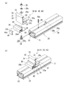
以下、本発明の一実施形態である太陽電池モジュールの固定構造を適用した太陽光発電システム1について、図1乃至図3に基づき説明する。なお、本実施形態では説明の便宜上、太陽光発電システム1が屋根上に設置された際、軒側となる方向を「一端側」と称し、棟側となる方向を「他端側」と称する。図1に示すように、本実施形態の太陽光発電システム1は、傾斜した屋根上に複数(本実施形態では二つ)の太陽電池モジュール2を設置したものであり、屋根材(図示しない)上に複数取付けられた支持部材(図示しない)に支持される長尺の桟部材20と、その長手方向に対して直角方向に所定の間隔で配置された一対の桟部材20上に設置される太陽電池モジュール2を桟部材20へ固定する固定手段30とを備えている。以下、各部材の構成について詳細に説明する。
Hereinafter, a solar power generation system 1 to which a solar cell module fixing structure according to an embodiment of the present invention is applied will be described with reference to FIGS. 1 to 3. In the present embodiment, for convenience of explanation, when the photovoltaic power generation system 1 is installed on the roof, the direction on the eaves side is referred to as “one end side”, and the direction on the ridge side is referred to as “other end side”. . As shown in FIG. 1, the photovoltaic power generation system 1 of the present embodiment has a plurality of (two in the present embodiment)
太陽電池モジュール2は、図1に示すように、複数の太陽電池セルを有し外形が矩形状で板状の太陽電池パネル2aと、太陽電池パネル2aの外周辺を支持する長尺の枠体2bとを備えており、平面視において長辺が短辺の約2倍の長さとなる長方形状に形成されている。また、枠体2bは、桟部材20の長手方向と平行な方向に延出されたフランジ部2cと、フランジ部2cの外縁から上方に屈曲した立壁部2dとを有している。
As shown in FIG. 1, the
桟部材20は、図2に示すように、アルミニウム等の金属の押出型材からなり、外形が略矩形状の同一断面形状で長尺状に形成されている。この桟部材20は、両側面にそれぞれ開口し略十字状の溝とされた第一保持部21と、上面に開口し逆T字状の溝とされた第二保持部22とを備えている。第一保持部21は、略十字状の溝における上下方向の溝内に、桟部材20を支持部材に取り付けるための六角ナット状の締結部材(図示しない)を回転不能且つ桟部材20の長手方向へスライド可能に保持することができる。また、第二保持部22は、根角ボルト等の締結部材26の雄ねじ部26aが上面から突出するように、逆T状の溝内に締結部材26の頭部26bを回転不能且つ桟部材20の長手方向へスライド可能に保持することができる。なお、桟部材20では、上面の第二保持部22が幅方向の略中央に配置されている。ここで、第二保持部22が本発明の保持部に相当する。
As shown in FIG. 2, the
固定手段30は、図1及び図2に示すように、複数の桟部材20上に設置された太陽電池モジュール2を桟部材20へ固定するものであり、第一固定部材30a及び第二固定部材30bと、桟部材20に保持される締結部材26と、締結部材26に締結される被締結部材28とを備えている。
As shown in FIGS. 1 and 2, the fixing means 30 fixes the
第一固定部材30aは、太陽電池モジュール2の上面に上方から当接可能とされ、桟部材20の長手方向と平行な方向へ延びた第一上側当接片32及び第二上側当接片33と、第一上側当接片32及び第二上側当接片33の境界部分から下方へ延出した板状の軸部31と、軸部31の途中から桟部材20の長手方向と平行な他端側へ延び、太陽電池モジュール2の下面に当接可能な下側当接片37と、下側当接片37と桟部材20との間に所定の空間が形成されるように、軸部31の下端から下側当接片37と平行に他端側へ延びると共に桟部材20上に載置された取着片38とを備えている。ここで、第一上側当接片32及び第二上側当接片33が本発明の上側当接片に相当する。
The first fixing
第一固定部材30aについてさらに詳しく説明すると、第一上側当接片32及び第二上側当接片33の先端部分には、垂直下方に延出された第一垂下片34及び第二垂下片35がそれぞれ形成されており、これらの第一垂下片34及び第二垂下片35を太陽電池モジュール2の立壁部2dに係止させることが可能になっている。なお、第二垂下片35の下端には、他端側に向かって次第に低くなる傾斜面が形成されている。
The
また、下側当接片37は第二上側当接片33よりも長く延出されており、下側当接片37から第二上側当接片33までの高さと下側当接片37の長さとが略等しくなっている。また、第二垂下片35の下方に位置する下側当接片37の上面には、太陽電池モジュール2の一端側下部側面が当接するストッパー37bが上方に突出して形成されている。また、取着片38の先端には、下側当接片37の底面に繋がる壁部38bが立設されており、下側当接片37、軸部31の下部、取着片38、及び壁部38bによって断面矩形の角筒状に形成されている。
In addition, the
また、取着片38には、締結部材26が挿通可能な第一開口38aが形成され、下側当接片37には、被締結部材28が通過可能な長孔37aが第一開口38aと対向して形成されている。特に長孔37aの長手方向の大きさは、被締結部材28の径方向の大きさに作業者の指(例えば親指と人差し指)の厚みに相当する大きさを加えた大きさよりも大きく(例えば5cm)、被締結部材28を二本の指で摘んだまま下側当接片37の下方の空間内に被締結部材28を挿入することができる。被締結部材28は、下側当接片37の下方の空間に配置され、桟部材20の第二保持部22によって保持され第一開口38aを通して上方に延び出させた締結部材26(根角ボルト)の雄ねじ部26aに螺合可能なものであり、本実施形態ではナットで構成されている。なお、この被締結部材28は、平ワッシャ28a及びスプリングワッシャ28bを介して締結部材26に螺合される。
The
一方、第二固定部材30bは、第一固定部材30aの軸部31を挟んで下側当接片37の反対側に配置され、太陽電池モジュール2と桟部材20との間に挿入されることで、軸部31を挟んで両側に配置される太陽電池モジュール2を同じ高さに支持できる載置部36を備えている。なお、載置部36は、下面に溝部を有する断面C字形の角筒状とされており、載置部36の内側の四隅部分には断面略C字形状のビス止部36aが形成されている。また、第二垂下片35の下方に位置する載置部36の上面には、上方に突出し太陽電池モジュール2の他端側側面が当接可能なストッパー40が形成されている。
On the other hand, the second fixing
また、第二固定部材30bは、載置部36の下端から桟部材20の長手方向と平行な方向に他端側へ延びると共に、取着片38と桟部材20との間で挟持される挟持片39をさらに備えており、第一固定部材30aが締結部材26及び被締結部材28によって桟部材20に固定されると、挟持片39が挟持されることで第二固定部材30bも桟部材20に固定される。なお、挟持片39には、締結部材26の雄ねじ部26aを挿通させる第二開口39aが形成されている。
The second fixing
なお、第一固定部材30a及び第二固定部材30bは、いずれも同一断面形状で長尺状に形成されたアルミニウム等の金属の押出型材を切断したものであり、夫々に穿設された第一開口38a、長孔37a、及び第二開口39aは切削加工によって形成されている。
Each of the first fixing
載置部36では軸部31と反対側の部位に、薄いステンレス等の板金をプレス加工により断面略コ字形に成形したアース部材45が外嵌されており、アース部材45の上面及び下面にそれぞれ形成された突起45aを太陽電池モジュール2の枠体2bと桟部材20の上面に突き刺すことにより、枠体2bと桟部材20とがアース部材45を介して電気的に接続される。
In the mounting
また、太陽光発電システム1は、太陽光発電システム1の一端側端部に配置され、太陽電池モジュール2及び桟部材20の端面を覆うように、固定手段30及び桟部材20へ固定される軒カバー50と、太陽光発電システム1の他端側端部に配置され、桟部材20の他端側端面を覆うように、ビス52によって固定手段30へ固定される端面カバー51とをさらに備えている。
The solar power generation system 1 is disposed at one end of the solar power generation system 1 and is fixed to the fixing means 30 and the
軒カバー50は、アルミニウム等の金属の押出型材からなる同一断面形状の長尺部材であり、図1に示すように、所定長さの底部50aと、底部50aの他端側端部から上方へ立上る立壁部50bと、立壁部50bの上端から底部50aと平行に延びる天部50cと、天部50cの先端から固定手段30の上端と同じ高さまで立上がる段部50dと、段部50dの上端から底部50aよりも外側且つ下側で斜め下方へ延びる側壁部50eとを備えている。そして、底部50aには、固定手段30の載置部36の上面に摺接する断面半円状の突起部50fが下方に突出して形成され、立壁部50bの上端には、上方に突出し固定手段30の第一垂下片34に係止可能な係止片50gが形成され、さらに、側壁部50eの下端には、桟部材20の底面側に係止可能な係止爪部50hが形成されている。
The eaves cover 50 is a long member having the same cross-sectional shape made of a metal extrusion mold material such as aluminum. As shown in FIG. 1, the bottom 50 a having a predetermined length and the other end of the bottom 50 a upward from the end. A standing
次に、本実施形態の太陽光発電システム1における太陽電池モジュール2の固定方法を説明する。なお、以下の説明において、太陽光発電システム1の端部に用いられる固定手段30と、太陽電池モジュール2同士の間に配置される固定手段30とを区別する必要がある場合には、太陽光発電システム1の一端側端部に配置された固定手段30を「軒側固定手段41」とし、太陽光発電システム1の他端側端部に配置された固定手段30を「棟側固定手段42」とし、太陽電池モジュール2同士の間に配置される固定手段30を「中側固定手段43」として説明する。また、一端側に配置される太陽電池モジュール2を「第一モジュール2x」とし、他端側に配置される太陽電池モジュール2を「第二モジュール2y」として説明する。ここで、軒側固定手段41が本発明の一端側固定手段に相当し、中側固定手段43が本発明の他端側固定手段に相当する。
Next, the fixing method of the
まず、太陽光発電システム1を設置する屋根に対し、設置する太陽電池モジュール2の数や、設置パターンに応じて、桟部材20を設置する。
First, the
次に、軒側固定手段41の第一固定部材30a及び第二固定部材30bを締結部材26及び被締結部材28によって仮組みする。詳しくは、締結部材26の雄ねじ部26aを挟持片39の第二開口39a及び取着片38の第一開口38aへ順に挿入し、取着片38の第一開口38aから突出する雄ねじ部26aの先端に、平ワッシャ28a及びスプリングワッシャ28bを通して、被締結部材28(ナット)を取付ける。また、雄ねじ部26aの先端に被締結部材28を取付ける際には、被締結部材28を指で摘んだまま下側当接片37に形成された長孔37aを通過して下側当接片37と取着片38との間の空間に挿入し、被締結部材28を摘んだまま締結部材26を回転させることで、締結部材26及び被締結部材28を螺合させる。つまり、「仮組み」とは、第一固定部材30aの取着片38と第二固定部材30bの挟持片39とが互いに重ねられ、締結部材26に被締結部材28が螺合されることで一体的に構成されているが、締結部材26及び被締結部材28が締め付けられておらず、第一固定部材30a及び第二固定部材30bを桟部材20の長手方向にスライドさせること、及び第一固定部材30aに対して第二固定部材30bを許容範囲内である程度変位させることが可能な状態である。
Next, the first fixing
そして、このように仮組みされた軒側固定手段41を、締結部材26の頭部26bを桟部材20の第二保持部22内へ挿入することで、桟部材20の長手方向にスライドさせ、桟部材20の所定位置、具体的には、軒側固定手段41の載置部36における一端側の面が桟部材20の一端側端面と略一致する位置に配置する。なお、桟部材20の第二保持部22にビス48を上方からねじ込み、ビス48の頭部48aを第二保持部22内に突出させることにより、軒側固定手段41が屋根の傾斜に沿って桟部材20の一端側から外れないようにする。
And the eaves-side fixing means 41 temporarily assembled in this way is slid in the longitudinal direction of the
その後、締結部材26の雄ねじ部26aに被締結部材28を締め付け、軒側固定手段41を所定位置で固定する。なお、この締め付けの際には工具が用いられ、工具の先端を、下側当接片37に形成された長孔37aを通して下側当接片37の下方の空間に挿入することで、被締結部材28を回転させることが可能となる。
Thereafter, the fastened
その後、第二上側当接片33と下側当接片37との間に、第一モジュール2xの一端側を挿入する。詳しくは、下側当接片37上に、第一モジュール2xを、他端側が高くなるように傾斜した状態で載置し(図3(a)参照)、その後、軸部31側に滑らせながら下側当接片37と平行になるように矢印R方向に回動させる。これにより、第一モジュール2xの一端側が第一固定部材30aの第二上側当接片33と下側当接片37との間に挿入され、第一モジュール2xの一端側が桟部材20に固定される(図3(b)参照)。なお、第一モジュール2xの枠体2bには立壁部2dが備えられ、第二上側当接片33の先端に第二垂下片35が備えられているため、太陽電池モジュール2を回動させながら挿入することにより、立壁部2dが第二垂下片35と軸部31との間に嵌め込まれる。また、第二垂下片35の下端には、他端側に向かって次第に低くなる傾斜面が形成されているため、第二上側当接片33と下側当接片37との間に第一モジュール2xの一端側を回動させながら挿入する際、立壁部2dが第二垂下片35に下側から当接することがあっても、傾斜面によって第二垂下片35の内側(係止される側)に案内することができる。
Thereafter, one end side of the
次に、第一モジュール2xの他端側に、中側固定手段43を取り付ける。なお、中側固定手段43においても、仮組みされた状態で、締結部材26の頭部26bを桟部材20の他端側から第二保持部22内へ挿入し、中側固定手段43全体を桟部材20に沿ってスライドさせる。なお、この状態では、まだ仮組みの状態であり、桟部材20の長手方向へスライドさせることができると共に、第一固定部材30a及び第二固定部材30bを許容範囲内で相対的に変位させることが可能である。また、締結部材26の頭部26bが桟部材20の第二保持部22内にある状態で、第一固定部材30aを上方に持ち上げることが可能である。
Next, the middle side fixing means 43 is attached to the other end side of the
そこで、まず中側固定手段43の載置部36が第一モジュール2xの他端側底面と桟部材20との間に挿入されるように、第二固定部材30bを一端側に向かって変位させる(図3(c)参照)。詳しくは、載置部36に形成されたストッパー40を第一モジュール2xの他端側の底部側面に当接させた上で、第一モジュール2xの他端側底面を載置部36に載置する。その後、第二固定部材30bを変位させることなく、第一固定部材30aの第一上側当接片32に形成された第一垂下片34を、第一モジュール2xの立壁部2dに上方から係止させるように第一固定部材30aを下方に変位させる。すると、第一上側当接片32が第一モジュール2xの他端側上面に当接すると共に、第一固定部材30aの取着片38が挟持片39の上に重ねられる。そこで、工具を用いて被締結部材28を締結部材26の雄ねじ部26aに締め付け、中側固定手段43を固定する(図3(d)参照)。これにより、第一モジュール2xの他端側は、底面が載置部36に載置され、上面が第一上側当接片32及び第一垂下片34によって係止された状態となる。また、この際、載置部36に外嵌されたアース部材45によって第一モジュール2xの枠体2bと桟部材20とが電気的に接続される。
Therefore, first, the second fixing
次に、中側固定手段43の第二上側当接片33と下側当接片37との間に、第二モジュール2yの一端側を差し込み(図3(e)参照)、さらに、第二モジュール2yの他端側を棟側固定手段42によって桟部材20に固定する(図3(f)参照)。なお、これらの方法は、図3(a)〜(d)を用いて説明した上記の固定方法と同様であるため、ここでは詳細な説明を省略する。
Next, one end side of the
そして、軒側固定手段41及び桟部材20の一端側に軒カバー50を取付け、棟側固定手段42に端面カバー51を取付ける。軒カバー50を取付けるには、まず、係止片50gを軒側固定手段41の第一垂下片34に斜め下方から係止させると共に突起部50fを載置部36の上面に載せ、その後、係止片50g及び第一垂下片34の係止状態を維持したまま、軒カバー50の下部部分を桟部材20側に押し込み、係止爪部50hを桟部材20の底面側に係止させる。また、軒カバー50の側壁部50eに形成されたV字型の溝(図示しない)を通して、一端側からビス50iを載置部36の側面に締め付けることにより、軒カバー50を軒側固定手段41に固定する。
Then, the eaves cover 50 is attached to one end side of the eaves-side fixing means 41 and the
ところで、太陽電池モジュール2を屋根の流れ方向だけでなく流れ方向に対して直角方向(横方向)へも複数配置する場合、固定される桟部材20が異なるので、横方向に隣接した太陽電池モジュール2同士の高さが異なってしまうことがある。この場合には、桟部材20と固定手段30との間に所定厚さのスペーサを挿入して固定手段30を締結固定することで太陽電池モジュール2同士の高さを調整する。
By the way, in the case where a plurality of
このように、本実施形態によれば、太陽電池モジュール2の一端側を桟部材20に固定するための固定手段30を、太陽電池モジュール2を設置する前に桟部材20に固定することができる。すなわち、複数の太陽電池モジュール2を設置する場合には、一端側から順番に太陽電池モジュール2を固定しながら並べることができる。したがって、太陽電池モジュール2上での作業がなくなり、太陽電池モジュール2の設置にかかる作業を一層容易なものとすることができる。
Thus, according to this embodiment, the fixing means 30 for fixing one end side of the
また、本実施形態によれば、締結部材26及び被締結部材28が太陽電池モジュール2の下方に配置されるため、太陽電池モジュール2同士の間にこれらを配置するためのスペースを確保する必要がなくなり、太陽電池モジュール2同士の隙間を極力小さくすることができる。特に、隣接した太陽電池モジュール2が、第一固定部材30aの軸部31のみを挟んで支持されるため、太陽電池モジュール2同士を可及的に接近させることができる。したがって、屋根の面積に対する太陽電池モジュール2の面積の割合を大きくし、発電効率を高めることが可能となる。また、太陽電池モジュール2同士の隙間を覆うカバーが不要となり、ひいては部品点数が少なくなり、コストを低減することができると共に、取付けにかかる手間を簡略化することができる。
Moreover, according to this embodiment, since the
また、本実施形態によれば、第一上側当接片32を備える第一固定部材30aと、載置部36を備える第二固定部材30bとを、別々の部材で構成しているため、一端側が既に軒側固定手段41によって固定され桟部材20に沿って配置されている第一モジュール2xに対しても、その他端側を中側固定手段43の第一上側当接片32及び載置部36によって固定することが可能となる。したがって、第一上側当接片32と載置部36とを一体で形成したものと比べ、作業性を良くすることができる。
Moreover, according to this embodiment, since the
詳しく説明すると、仮に第一固定部材30aと第二固定部材30bとを一体成形した場合には、第一上側当接片32と載置部36との間隔が一定となるため、これを他端側から太陽電池モジュール2と桟部材20との間に挿入させようとすると、立壁部2dと第一垂下片34とが突き当たることになる。なお、太陽電池モジュール2を他端側が高くなるように傾斜させた状態で、固定手段30を桟部材20の長手方向に対して直角方向の端面側から嵌合し、太陽電池モジュール2の他端側に沿ってスライドさせるようにすれば、太陽電池モジュール2の他端側に固定手段30を取付けることができるが、これによれば以下の不具合が生じる。すなわち、この方法によれば、固定手段30を固定するための締結部材26のみを桟部材20の第二保持部22に保持させておき、太陽電池モジュール2を回動させながら、締結部材26の雄ねじ部26aが取着片38の第一開口38aに挿入されるようにしなければならず、雄ねじ部26aと第一開口38aとの位置合せに手間がかかることになる。これに対し、本実施形態によれば、別々の部材で構成することで、締結部材26及び被締結部材28によって固定手段30全体を仮組みした状態で締結部材26を桟部材20の第二保持部22に保持させることが可能となり、作業性を大幅に高めることができる。
More specifically, if the first fixing
また、本実施形態によれば、第一固定部材30aの下側当接片37は、第二上側当接片33よりも長く延びているため、太陽電池モジュール2を、下側当接片37上に、他端側が高くなるように傾斜した状態で載置し、その後、軸部31側に滑らせながら回動させて、太陽電池モジュール2の一端側を第二上側当接片33と下側当接片37との間に挿入することができる。このため、太陽電池モジュール2を桟部材20と平行にしてから真直ぐ挿入させる場合と比べ、極めて容易に作業することができる。例えば、太陽電池モジュール2を桟部材20と平行にして挿入させる場合には、桟部材20から僅かに浮かした状態で桟部材20に沿って移動させる必要があることから、一人の作業者だけでは作業を行うことが極めて困難であるが、本実施形態では、下側当接片37上に太陽電池モジュール2を傾けた状態で載置し、その太陽電池モジュール2を滑らせて回転させながら挿入しているので、一人の作業者でも容易に作業することができ、作業性を良くすると共に、労働負担を低減することができる。また、本実施形態では、太陽電池モジュール2の枠体2bに立壁部2dを有すると共に、第二上側当接片33の先端に第二垂下片35を備えているが、このような場合でも、太陽電池モジュール2を回動させながら挿入することにより、立壁部2dが第二垂下片35に突き当たることなく、第二垂下片35と軸部31との間に立壁部2dを嵌め込むことができる。
Moreover, according to this embodiment, since the
また、本実施形態によれば、載置部36を有する第二固定部材30bは、挟持片39を備えるため、第一モジュール2xに対して載置部36の挿入作業を行った後、第一垂下片34の係止作業を行うようにすれば、挟持片39の上に取着片38を重ね合わせ、固定手段30全体を一組の締結部材26及び被締結部材28によって固定することができる。したがって、固定作業をさらに容易なものとすることができる。
Moreover, according to this embodiment, since the 2nd fixing
また、本実施形態によれば、載置部36は角筒状に形成されているため、強靭な構造となり、例えば強風等によって太陽電池モジュール2から作用する荷重が比較的大きくなっても、しっかりと支持することができる。
Moreover, according to this embodiment, since the mounting
さらに、本実施形態によれば、固定手段30の下側当接片37に長孔37aが形成され、被締結部材28と共に作業者の指を挿入することができるため、被締結部材28に対する締結部材26の螺合を容易に行うことができる。
Furthermore, according to the present embodiment, since the
以上、本発明について好適な実施形態を挙げて説明したが、本発明はこれらの実施形態に限定されるものではなく、以下に示すように、本発明の要旨を逸脱しない範囲において、種々の改良及び設計の変更が可能である。 The present invention has been described with reference to preferred embodiments. However, the present invention is not limited to these embodiments, and various modifications can be made without departing from the spirit of the present invention as described below. And design changes are possible.
すなわち、上記実施形態では、太陽電池モジュール2を屋根の流れ方向に対して二つ配置したものを示したが、太陽電池モジュール2を一つのみとしてもよく、あるいは三つ以上配置してもよい。また、上記実施形態では、一つの太陽電池モジュール2を二つの桟部材20で支持するものを示したが、三つ以上の桟部材20で支持するようにしてもよい。
That is, in the above embodiment, two
また、上記の実施形態では、流れ方向にのみ太陽電池モジュール2を配置するものを示したが、屋根の横方向に対しても太陽電池モジュール2を複数配置してもよい。
In the above embodiment, the
また、上記実施形態では、桟部材20によって保持される締結部材26として根角ボルトを用い、締結部材26に締結される被締結部材28としてナットを用いるものを示したが、締結部材26としてナットを用い、被締結部材28としてボルトを用いるようにしてもよい。
In the above-described embodiment, a square bolt is used as the
また、上記実施形態では、固定手段30及び桟部材20の一端側端面を軒カバー50で覆い、桟部材20の他端側端面を端面カバー51で覆うものを示したが、桟部材20の両側の端面をいずれも端面カバー51で覆うようにしてもよい。
Moreover, in the said embodiment, although the one end side end surface of the fixing means 30 and the
さらに、上記実施形態では、太陽電池モジュール2の枠体2bとして、フランジ部2c及び立壁部2dを有するものを示したが、フランジ部のみを有する枠体、またはフランジ部及び立壁部を備えない枠体を使用するようにしてもよい。
Furthermore, in the said embodiment, although what has the
2 太陽電池モジュール
2a 太陽電池パネル
2x 第一モジュール(太陽電池モジュール)
2y 第二モジュール(太陽電池モジュール)
20 桟部材
22 第二保持部(保持部)
26 締結部材
28 被締結部材
30 固定手段
30a 第一固定部材
30b 第二固定部材
31 軸部
32 第一上側当接片(上側当接片)
33 第二上側当接片(上側当接片)
36 載置部
37 下側当接片
37a 長孔
38 取着片
38a 第一開口
39 挟持片
39a 第二開口
41 軒側固定手段(一端側固定手段)
43 中側固定部材(他端側固定手段)
2
2y Second module (solar cell module)
20
26
33 Second upper contact piece (upper contact piece)
36 mounting
43 Middle fixing member (fixing means on the other end)
Claims (3)
該桟部材の上側に設置される太陽電池モジュールを前記桟部材に固定する固定手段と
を具備し、
前記桟部材は、前記固定手段を前記桟部材に締結するための締結部材を、長手方向へのみスライド可能に保持する保持部を上面に有し、
前記固定手段は、
太陽電池モジュールの上面に当接可能とされ、前記桟部材の前記長手方向と平行な方向へ延びた上側当接片、
該上側当接片の中央から下方へ延出した軸部、
該軸部の途中から前記桟部材の前記長手方向と平行な一方向へ前記上側当接片よりも長く延び、太陽電池モジュールの下面に当接可能な下側当接片、
及び、前記軸部の下端から前記下側当接片と平行な方向へ延び、前記下側当接片と前記桟部材との間に所定の空間を形成すると共に、前記桟部材上に載置され、前記締結部材または該締結部材に締結される被締結部材が挿入可能な第一開口を有する取着片、
を有する第一固定部材と、
該第一固定部材の前記軸部を挟んで前記下側当接片の反対側に配置され、前記下側当接片が当接する太陽電池モジュールとは異なる太陽電池モジュールと前記桟部材との間に挿入可能とされ、該太陽電池モジュールを、前記下側当接片が当接する太陽電池モジュールと同じ高さに載置する載置部、
及び、該載置部の下端から前記桟部材の前記長手方向と平行な方向へ延びると共に、前記取着片の下側に配置され、前記締結部材または前記被締結部材が挿入可能な第二開口を有する挟持片
を有し前記第一固定部材とは別部材とされた第二固定部材と
を備える
ことを特徴とする太陽電池モジュールの固定構造。 A long bar member arranged on the roofing material;
A fixing means for fixing the solar cell module installed on the upper side of the crosspiece member to the crosspiece member,
The cross member has a holding portion on the upper surface for holding a fastening member for fastening the fixing means to the cross member so as to be slidable only in the longitudinal direction,
The fixing means includes
An upper contact piece that is capable of contacting the upper surface of the solar cell module and extends in a direction parallel to the longitudinal direction of the crosspiece member;
A shaft portion extending downward from the center of the upper contact piece,
A lower contact piece that extends from the middle of the shaft portion in a direction parallel to the longitudinal direction of the crosspiece member in a direction longer than the upper contact piece and is capable of contacting the lower surface of the solar cell module;
And it extends in a direction parallel to the lower contact piece from the lower end of the shaft portion, forms a predetermined space between the lower contact piece and the crosspiece member, and is placed on the crosspiece member An attachment piece having a first opening into which the fastening member or a fastened member fastened to the fastening member can be inserted,
A first fixing member having
Between the solar cell module and the crosspiece member, which is disposed on the opposite side of the lower contact piece across the shaft portion of the first fixing member and different from the solar cell module with which the lower contact piece contacts. A mounting portion for mounting the solar cell module at the same height as the solar cell module with which the lower contact piece abuts,
And a second opening that extends from a lower end of the mounting portion in a direction parallel to the longitudinal direction of the crosspiece member and is disposed below the attachment piece and into which the fastening member or the fastening member can be inserted. A fixing structure for a solar cell module, comprising: a second fixing member that includes a sandwiching piece that includes: a second fixing member that is different from the first fixing member.
太陽電池モジュールの一端側を前記桟部材に固定する前記固定手段を一端側固定手段とし、前記締結部材が前記桟部材の前記保持部によって保持され、且つ所定位置に固定された前記一端側固定手段の前記下側当接片上に、太陽電池モジュールの一端側を、他端側が高くなるように傾斜した状態で載置すると共に、前記軸部側に滑らせながら前記下側当接片と平行になるように太陽電池モジュールを回動させることで、太陽電池モジュールの一端側を前記上側当接片と前記下側当接片との間に挿入して固定し、
太陽電池モジュールの他端側を前記桟部材に固定する前記固定手段を他端側固定手段とし、前記締結部材及び前記被締結部材によって仮組みされた前記他端側固定手段を、前記締結部材が前記桟部材の前記保持部によって保持された状態で前記桟部材の前記長手方向に沿ってスライドさせ、前記第二固定部材の前記載置部を太陽電池モジュールの他端側と前記桟部材との間に挿入し、その後、前記第一固定部材の前記上側当接片を上方から太陽電池モジュールの上面に当接させると共に、前記締結部材及び前記被締結部材を締結して前記他端側固定手段を前記桟部材に固定することにより、太陽電池モジュールの他端側を固定する
ことを特徴とする太陽電池モジュールの固定方法。 A solar cell module fixing method for constructing a solar cell module fixing structure according to claim 1 or 2,
The fixing means for fixing one end side of the solar cell module to the crosspiece member is used as one end side fixing means, and the fastening member is held by the holding portion of the crosspiece member and fixed at a predetermined position. One end of the solar cell module is placed on the lower abutting piece in an inclined state so that the other end is raised, and is parallel to the lower abutting piece while sliding to the shaft side. By rotating the solar cell module so that the one end side of the solar cell module is inserted and fixed between the upper contact piece and the lower contact piece,
The fixing means for fixing the other end side of the solar cell module to the crosspiece member is the other end side fixing means, and the other end side fixing means temporarily assembled by the fastening member and the fastened member is the fastening member. The slide member is slid along the longitudinal direction of the cross member while being held by the holding portion of the cross member, and the mounting portion of the second fixing member is placed between the other end side of the solar cell module and the cross member. And then the upper contact piece of the first fixing member is brought into contact with the upper surface of the solar cell module from above, and the fastening member and the fastened member are fastened to fix the other end side fixing means. A method for fixing a solar cell module, wherein the other end side of the solar cell module is fixed to the crosspiece member.
Priority Applications (1)
| Application Number | Priority Date | Filing Date | Title |
|---|---|---|---|
| JP2012122693A JP5891109B2 (en) | 2012-05-30 | 2012-05-30 | Solar cell module fixing structure and solar cell module fixing method |
Applications Claiming Priority (1)
| Application Number | Priority Date | Filing Date | Title |
|---|---|---|---|
| JP2012122693A JP5891109B2 (en) | 2012-05-30 | 2012-05-30 | Solar cell module fixing structure and solar cell module fixing method |
Publications (2)
| Publication Number | Publication Date |
|---|---|
| JP2013249579A JP2013249579A (en) | 2013-12-12 |
| JP5891109B2 true JP5891109B2 (en) | 2016-03-22 |
Family
ID=49848538
Family Applications (1)
| Application Number | Title | Priority Date | Filing Date |
|---|---|---|---|
| JP2012122693A Active JP5891109B2 (en) | 2012-05-30 | 2012-05-30 | Solar cell module fixing structure and solar cell module fixing method |
Country Status (1)
| Country | Link |
|---|---|
| JP (1) | JP5891109B2 (en) |
Families Citing this family (5)
| Publication number | Priority date | Publication date | Assignee | Title |
|---|---|---|---|---|
| JP6358693B2 (en) * | 2014-02-16 | 2018-07-18 | 株式会社 丸光 | Solar panel mounting bracket |
| JP6749798B2 (en) * | 2016-06-27 | 2020-09-02 | ソーラーフロンティア株式会社 | Fixture for panel array |
| JP6668224B2 (en) * | 2016-12-01 | 2020-03-18 | 株式会社栄信 | Grounding bracket installation structure |
| JP6904708B2 (en) * | 2017-01-05 | 2021-07-21 | 高島株式会社 | Fixing device |
| JP7301776B2 (en) * | 2020-03-24 | 2023-07-03 | ミサワホーム株式会社 | Exterior wall structure |
Family Cites Families (5)
| Publication number | Priority date | Publication date | Assignee | Title |
|---|---|---|---|---|
| JP4365450B1 (en) * | 2009-05-01 | 2009-11-18 | 株式会社屋根技術研究所 | Solar cell module fixing structure, solar cell module frame and fixing member |
| JP5202430B2 (en) * | 2009-05-11 | 2013-06-05 | 株式会社屋根技術研究所 | Solar cell module fixing structure |
| JP5113859B2 (en) * | 2010-02-02 | 2013-01-09 | 株式会社屋根技術研究所 | Fixed member |
| JP5611707B2 (en) * | 2010-08-02 | 2014-10-22 | 株式会社屋根技術研究所 | Plate module fixing structure |
| JP5388311B2 (en) * | 2011-07-15 | 2014-01-15 | シャープ株式会社 | Solar cell module support structure, solar power generation system using the support structure, and solar cell module installation method |
-
2012
- 2012-05-30 JP JP2012122693A patent/JP5891109B2/en active Active
Also Published As
| Publication number | Publication date |
|---|---|
| JP2013249579A (en) | 2013-12-12 |
Similar Documents
| Publication | Publication Date | Title |
|---|---|---|
| AU2021201458B2 (en) | Photovoltaic module mounting assembly | |
| JP5202430B2 (en) | Solar cell module fixing structure | |
| JP5705380B2 (en) | Solar cell module fixing structure | |
| EP2167755B1 (en) | Adjustable mounting assembly for standing seam panels | |
| KR101390571B1 (en) | PV module mounting and support assembly and mounting method | |
| JP5891109B2 (en) | Solar cell module fixing structure and solar cell module fixing method | |
| KR20140085420A (en) | Solar cell module fixing structure | |
| JP6865403B2 (en) | Solar power generator | |
| JP2013087579A (en) | Fixture device for solar cell module installation apparatus | |
| US20160109054A1 (en) | Panel support structure | |
| US10103681B2 (en) | Retaining device for solar cell module | |
| WO2012121147A1 (en) | Mounting base for solar cell module, method for constructing mounting base, and solar photovoltaic power generation system with mounting base | |
| US10224864B2 (en) | Solar cell module mounting device | |
| JP3202583U (en) | Support structure for photovoltaic panels | |
| JP5686771B2 (en) | Solar cell module fixing structure and solar cell module fixing method | |
| JP6661320B2 (en) | Solar cell module installation structure, installation method, and solar power generation system using the installation structure | |
| JPWO2018061696A1 (en) | Solar power generator | |
| JP2015055042A (en) | Installation member for equipment and equipment installation roof | |
| JP6474185B2 (en) | Solar power panel construction method | |
| JP5882704B2 (en) | Solar cell panel laying structure and solar cell panel fixing member | |
| JP6192453B2 (en) | Roof structure, solar cell module fixture, solar cell module mounting structure, and solar cell module mounting method | |
| JP5965376B2 (en) | Solar cell module support structure and solar power generation system using the support structure | |
| JP6771201B2 (en) | Solar power generator | |
| JP6554442B2 (en) | Support bracket for solar panel mounting base | |
| JP5882705B2 (en) | Solar panel eaves fixture and roof structure |
Legal Events
| Date | Code | Title | Description |
|---|---|---|---|
| A621 | Written request for application examination |
Free format text: JAPANESE INTERMEDIATE CODE: A621 Effective date: 20150310 |
|
| A977 | Report on retrieval |
Free format text: JAPANESE INTERMEDIATE CODE: A971007 Effective date: 20160129 |
|
| TRDD | Decision of grant or rejection written | ||
| A01 | Written decision to grant a patent or to grant a registration (utility model) |
Free format text: JAPANESE INTERMEDIATE CODE: A01 Effective date: 20160209 |
|
| A61 | First payment of annual fees (during grant procedure) |
Free format text: JAPANESE INTERMEDIATE CODE: A61 Effective date: 20160222 |
|
| R150 | Certificate of patent or registration of utility model |
Ref document number: 5891109 Country of ref document: JP Free format text: JAPANESE INTERMEDIATE CODE: R150 |
|
| R250 | Receipt of annual fees |
Free format text: JAPANESE INTERMEDIATE CODE: R250 |
|
| R250 | Receipt of annual fees |
Free format text: JAPANESE INTERMEDIATE CODE: R250 |