KR20140085420A - Solar cell module fixing structure - Google Patents
Solar cell module fixing structure Download PDFInfo
- Publication number
- KR20140085420A KR20140085420A KR1020147005435A KR20147005435A KR20140085420A KR 20140085420 A KR20140085420 A KR 20140085420A KR 1020147005435 A KR1020147005435 A KR 1020147005435A KR 20147005435 A KR20147005435 A KR 20147005435A KR 20140085420 A KR20140085420 A KR 20140085420A
- Authority
- KR
- South Korea
- Prior art keywords
- solar cell
- fixing
- fixing member
- cell module
- spacer
- Prior art date
Links
- 125000006850 spacer group Chemical group 0.000 claims abstract description 88
- NJPPVKZQTLUDBO-UHFFFAOYSA-N novaluron Chemical compound C1=C(Cl)C(OC(F)(F)C(OC(F)(F)F)F)=CC=C1NC(=O)NC(=O)C1=C(F)C=CC=C1F NJPPVKZQTLUDBO-UHFFFAOYSA-N 0.000 claims description 33
- 238000000034 method Methods 0.000 claims 2
- 238000003780 insertion Methods 0.000 claims 1
- 230000037431 insertion Effects 0.000 claims 1
- 238000009434 installation Methods 0.000 description 16
- 239000000463 material Substances 0.000 description 11
- 230000003014 reinforcing effect Effects 0.000 description 6
- 238000012423 maintenance Methods 0.000 description 5
- 238000005553 drilling Methods 0.000 description 3
- 229910052782 aluminium Inorganic materials 0.000 description 2
- XAGFODPZIPBFFR-UHFFFAOYSA-N aluminium Chemical compound [Al] XAGFODPZIPBFFR-UHFFFAOYSA-N 0.000 description 2
- 238000010276 construction Methods 0.000 description 2
- 239000007769 metal material Substances 0.000 description 2
- 241000239290 Araneae Species 0.000 description 1
- 235000005881 Calendula officinalis Nutrition 0.000 description 1
- 240000000785 Tagetes erecta Species 0.000 description 1
- 239000004568 cement Substances 0.000 description 1
- 239000000919 ceramic Substances 0.000 description 1
- 230000000694 effects Effects 0.000 description 1
- 229910052751 metal Inorganic materials 0.000 description 1
- 239000002184 metal Substances 0.000 description 1
- 238000012986 modification Methods 0.000 description 1
- 230000004048 modification Effects 0.000 description 1
- 230000000149 penetrating effect Effects 0.000 description 1
- 238000010248 power generation Methods 0.000 description 1
- 230000000630 rising effect Effects 0.000 description 1
- 239000010454 slate Substances 0.000 description 1
- XLYOFNOQVPJJNP-UHFFFAOYSA-N water Substances O XLYOFNOQVPJJNP-UHFFFAOYSA-N 0.000 description 1
- 210000000707 wrist Anatomy 0.000 description 1
Images


Classifications
-
- H—ELECTRICITY
- H02—GENERATION; CONVERSION OR DISTRIBUTION OF ELECTRIC POWER
- H02S—GENERATION OF ELECTRIC POWER BY CONVERSION OF INFRARED RADIATION, VISIBLE LIGHT OR ULTRAVIOLET LIGHT, e.g. USING PHOTOVOLTAIC [PV] MODULES
- H02S20/00—Supporting structures for PV modules
-
- F—MECHANICAL ENGINEERING; LIGHTING; HEATING; WEAPONS; BLASTING
- F24—HEATING; RANGES; VENTILATING
- F24S—SOLAR HEAT COLLECTORS; SOLAR HEAT SYSTEMS
- F24S25/00—Arrangement of stationary mountings or supports for solar heat collector modules
- F24S25/60—Fixation means, e.g. fasteners, specially adapted for supporting solar heat collector modules
- F24S25/61—Fixation means, e.g. fasteners, specially adapted for supporting solar heat collector modules for fixing to the ground or to building structures
-
- F—MECHANICAL ENGINEERING; LIGHTING; HEATING; WEAPONS; BLASTING
- F24—HEATING; RANGES; VENTILATING
- F24S—SOLAR HEAT COLLECTORS; SOLAR HEAT SYSTEMS
- F24S25/00—Arrangement of stationary mountings or supports for solar heat collector modules
- F24S25/60—Fixation means, e.g. fasteners, specially adapted for supporting solar heat collector modules
- F24S25/63—Fixation means, e.g. fasteners, specially adapted for supporting solar heat collector modules for fixing modules or their peripheral frames to supporting elements
- F24S25/632—Side connectors; Base connectors
-
- F—MECHANICAL ENGINEERING; LIGHTING; HEATING; WEAPONS; BLASTING
- F24—HEATING; RANGES; VENTILATING
- F24S—SOLAR HEAT COLLECTORS; SOLAR HEAT SYSTEMS
- F24S25/00—Arrangement of stationary mountings or supports for solar heat collector modules
- F24S25/70—Arrangement of stationary mountings or supports for solar heat collector modules with means for adjusting the final position or orientation of supporting elements in relation to each other or to a mounting surface; with means for compensating mounting tolerances
-
- H—ELECTRICITY
- H02—GENERATION; CONVERSION OR DISTRIBUTION OF ELECTRIC POWER
- H02S—GENERATION OF ELECTRIC POWER BY CONVERSION OF INFRARED RADIATION, VISIBLE LIGHT OR ULTRAVIOLET LIGHT, e.g. USING PHOTOVOLTAIC [PV] MODULES
- H02S20/00—Supporting structures for PV modules
- H02S20/20—Supporting structures directly fixed to an immovable object
- H02S20/22—Supporting structures directly fixed to an immovable object specially adapted for buildings
- H02S20/23—Supporting structures directly fixed to an immovable object specially adapted for buildings specially adapted for roof structures
-
- F—MECHANICAL ENGINEERING; LIGHTING; HEATING; WEAPONS; BLASTING
- F24—HEATING; RANGES; VENTILATING
- F24S—SOLAR HEAT COLLECTORS; SOLAR HEAT SYSTEMS
- F24S25/00—Arrangement of stationary mountings or supports for solar heat collector modules
- F24S2025/01—Special support components; Methods of use
- F24S2025/013—Stackable support elements
-
- F—MECHANICAL ENGINEERING; LIGHTING; HEATING; WEAPONS; BLASTING
- F24—HEATING; RANGES; VENTILATING
- F24S—SOLAR HEAT COLLECTORS; SOLAR HEAT SYSTEMS
- F24S25/00—Arrangement of stationary mountings or supports for solar heat collector modules
- F24S25/60—Fixation means, e.g. fasteners, specially adapted for supporting solar heat collector modules
- F24S2025/6002—Fixation means, e.g. fasteners, specially adapted for supporting solar heat collector modules by using hooks
-
- Y—GENERAL TAGGING OF NEW TECHNOLOGICAL DEVELOPMENTS; GENERAL TAGGING OF CROSS-SECTIONAL TECHNOLOGIES SPANNING OVER SEVERAL SECTIONS OF THE IPC; TECHNICAL SUBJECTS COVERED BY FORMER USPC CROSS-REFERENCE ART COLLECTIONS [XRACs] AND DIGESTS
- Y02—TECHNOLOGIES OR APPLICATIONS FOR MITIGATION OR ADAPTATION AGAINST CLIMATE CHANGE
- Y02B—CLIMATE CHANGE MITIGATION TECHNOLOGIES RELATED TO BUILDINGS, e.g. HOUSING, HOUSE APPLIANCES OR RELATED END-USER APPLICATIONS
- Y02B10/00—Integration of renewable energy sources in buildings
- Y02B10/10—Photovoltaic [PV]
-
- Y—GENERAL TAGGING OF NEW TECHNOLOGICAL DEVELOPMENTS; GENERAL TAGGING OF CROSS-SECTIONAL TECHNOLOGIES SPANNING OVER SEVERAL SECTIONS OF THE IPC; TECHNICAL SUBJECTS COVERED BY FORMER USPC CROSS-REFERENCE ART COLLECTIONS [XRACs] AND DIGESTS
- Y02—TECHNOLOGIES OR APPLICATIONS FOR MITIGATION OR ADAPTATION AGAINST CLIMATE CHANGE
- Y02B—CLIMATE CHANGE MITIGATION TECHNOLOGIES RELATED TO BUILDINGS, e.g. HOUSING, HOUSE APPLIANCES OR RELATED END-USER APPLICATIONS
- Y02B10/00—Integration of renewable energy sources in buildings
- Y02B10/20—Solar thermal
-
- Y—GENERAL TAGGING OF NEW TECHNOLOGICAL DEVELOPMENTS; GENERAL TAGGING OF CROSS-SECTIONAL TECHNOLOGIES SPANNING OVER SEVERAL SECTIONS OF THE IPC; TECHNICAL SUBJECTS COVERED BY FORMER USPC CROSS-REFERENCE ART COLLECTIONS [XRACs] AND DIGESTS
- Y02—TECHNOLOGIES OR APPLICATIONS FOR MITIGATION OR ADAPTATION AGAINST CLIMATE CHANGE
- Y02E—REDUCTION OF GREENHOUSE GAS [GHG] EMISSIONS, RELATED TO ENERGY GENERATION, TRANSMISSION OR DISTRIBUTION
- Y02E10/00—Energy generation through renewable energy sources
- Y02E10/40—Solar thermal energy, e.g. solar towers
- Y02E10/47—Mountings or tracking
-
- Y—GENERAL TAGGING OF NEW TECHNOLOGICAL DEVELOPMENTS; GENERAL TAGGING OF CROSS-SECTIONAL TECHNOLOGIES SPANNING OVER SEVERAL SECTIONS OF THE IPC; TECHNICAL SUBJECTS COVERED BY FORMER USPC CROSS-REFERENCE ART COLLECTIONS [XRACs] AND DIGESTS
- Y02—TECHNOLOGIES OR APPLICATIONS FOR MITIGATION OR ADAPTATION AGAINST CLIMATE CHANGE
- Y02E—REDUCTION OF GREENHOUSE GAS [GHG] EMISSIONS, RELATED TO ENERGY GENERATION, TRANSMISSION OR DISTRIBUTION
- Y02E10/00—Energy generation through renewable energy sources
- Y02E10/50—Photovoltaic [PV] energy
Abstract
태양전지모듈의 고정구조(1)는, 태양전지모듈(9)과, 태양전지모듈(9)을 지지하는 제1고정부재(7)와, 제1고정부재(7)를 재치하는 재치부(20)를 구비하는 재치연결부(22), 재치연결부(22)로부터 연장된 경사연결부(25) 및 경사연결부(25)로부터 연장되어 지붕구조부재(2)의 구조면(8)을 따라 곡절된 접촉부(26)를 구비하는 제2고정부재(4)와, 제1고정부재(7) 및 제2고정부재(4) 사이에 다단으로 적층된 스페이서 부재(3)를 구비한다. 재치연결부(22)의 재치부(20)에는 재치면(20a)을 관통하는 장공형상의 장공부(29)가 형성되어, 제2고정부재(4)에 대한 제1고정부재(7)의 고정위치의 미세조정이 가능하게 된다.The fixing structure 1 of the solar cell module includes a solar cell module 9, a first fixing member 7 for supporting the solar cell module 9, a mounting portion for mounting the first fixing member 7 A tilted connection portion 25 extending from the mounting connection portion 22 and a tilted connection portion 25 extending from the tilted connection portion 25 and extending along the structural surface 8 of the roof structural member 2, And a spacer member 3 stacked in a plurality of stages between the first fixing member 7 and the second fixing member 4. The spacer member 3 includes a first fixing member 4 and a second fixing member 4, The elongated hole 29 is formed in the mounting portion 20 of the mountable connection portion 22 so as to penetrate through the placement surface 20a so that the fixing of the first fixing member 7 to the second fixing member 4 The position can be finely adjusted.
Description
본 발명은 태양전지모듈(太陽電池module)의 고정구조(固定構造)에 관한 것으로서, 특히 지붕위에 복수 개(複數 個)의 태양전지모듈을 고정하기 위한 고정부재(固定部材)를 구비하는 태양전지모듈의 고정구조에 관한 것이다.
BACKGROUND OF THE
건축물의 지붕위에 태양전지모듈을 설치하여 태양광에 의한 발전이 이루어지고 있다. 이때에 복수 개의 패널모양의 태양전지모듈을 지붕위에 고정하는 고정구조로서는, 예를 들면 지붕기와 등의 지붕자재가 부설되는 산자널(roofboard)에 소정의 간격으로 지붕고정기구를 부착한 뒤에, 당해 지붕고정기구에 긴 자(scale) 모양의 세로 문창살을 부착하고, 또한 복수의 세로 문창살 사이를 가설(架設)하도록 하여 복수의 가로 문창살을 소정의 간격으로 부착한 우물 정(井)자 모양의 부착 설치대를 형성하고, 가로 문창살 사이에서 태양전지모듈을 지지함으로써 지붕위에 고정하는 경우가 있다. 이 경우에는 지붕고정기구, 세로 문창살 등의 각종 부재를 필요로 하여, 부품수가 많아져 설비비용이 많아지는 문제가 있었다. 또한 그들의 부재를 발판이 나쁜 지붕위에서 조립하여야 하며, 설치에 필요한 작업공수가 많아져 작업비용이 많아지는 문제도 있었다.The solar cell module is installed on the roof of the building, and the solar power is being generated. At this time, as a fixing structure for fixing a plurality of panel-shaped solar cell modules on a roof, for example, a roof fixing mechanism is attached to a roofboard having roof materials such as roof tiles at predetermined intervals, A well-shaped attachment mounting structure in which a plurality of vertical frame sheets are attached at predetermined intervals so that a vertical frame sheet of a scale shape is attached to a fixing mechanism and a plurality of vertical frame sheets are staked, And there is a case where the solar cell module is fixed on the roof by supporting the solar cell module between the horizontal sheets. In this case, a variety of members such as a roof fixing mechanism and a longitudinal window pane are required, which increases the number of parts and increases the facility cost. Also, there is a problem that their members must be assembled on a roof having a bad footing, and the work cost required for installation increases.
본원 출원인은 상기 태양전지모듈의 고정구조에 관한 기술개발을 진행하여 우물 정자 모양의 부착 설치대의 구성을 생략하고, 건축물의 지붕위에 간단하고 또한 저비용으로 태양전지모듈을 설치가능한 고정구조를 제안하고 있다. 이것에 의하면 태양전지모듈에 있어서 처마측 및 마룻대측의 각각의 외측 가장자리를 복수의 고정부재에 의하여 지지하고, 또한 당해 고정부재를 설치대상인 지붕구조부재(지붕자재 혹은 건축구조부재 등)에 직접 고정할 수 있다(특허문헌1 참조). 이 고정구조는, 태양전지모듈의 외측 가장자리가 재치되는 재치부(載置部) 및 재치부의 하측에 구성되어 지붕자재에 고정하기 위한 고정부(固定部)를 구비하고, 지붕자재위에 설치되는 베이스부와, 베이스부의 재치부로부터 상방으로 연장되는 세움 설치부와, 세움 설치부의 상단(上端)으로부터 재치부와 평행하게 양측으로 연장되는 저지부(沮止部)를 구비하여, 재치부 및 저지부에 의하여 태양전지모듈의 외측 가장자리를 협지하여 지지할 수 있는 고정부재를 구비하여 구성되어 있다. 이에 따라 복수의 태양전지모듈을 한 방향측(예를 들면 처마측)으로부터 순차적으로 다른 방향측(예를 들면 마룻대측)을 향하여 고정할 수 있어, 태양전지모듈의 설치작업을 노동절약화할 수 있다. 또한 고정부재 자체는 태양전지모듈의 외측 가장자리를 따라 슬라이드 가능하게 형성되는 것으로서, 서까래 등의 지붕의 건축구조부재와 고정위치를 맞출 수 있어 고정부재 자체의 고정강도(固定强度)를 높일 수 있다. 또한 부착 설치대 등과 같은 별도의 구성을 필요로 하지 않기 때문에 부품수의 대폭적인 삭감이 가능하게 된다.
The applicant of the present application has proposed a fixing structure in which a solar cell module is installed on a roof of a building with simple and low cost by omitting the construction of a mounting stand with a pit shape . According to this structure, the outer edge of each of the eaves side and the pillar side of the solar cell module is supported by a plurality of fixing members, and the fixing member is fixed directly to the roof structural member (roofing material or building structural member) (See Patent Document 1). The stationary structure includes a mounting portion on which an outer edge of the solar cell module is mounted and a fixing portion for fixing the mounting portion to a roof material on the lower side of the mounting portion, And a holding portion extending from the upper end of the raised mounting portion to both sides in parallel with the placement portion so as to extend from the placement portion of the placement portion to the placement portion, And a fixing member capable of holding and supporting the outer edge of the solar cell module. As a result, the plurality of solar cell modules can be fixed from one direction side (for example, from the eaves side) to the other direction side (for example, the marginal side) sequentially, . Further, the fixing member itself is slidably formed along the outer edge of the solar cell module, and can be fixed to a building structural member of a roof such as a rafter or the like, so that the fixing strength of the fixing member itself can be increased. In addition, since a separate structure such as an attachment mounting base is not required, the number of parts can be greatly reduced.
그러나 상기한 태양전지모듈의 고정구조는 하기에 열거된 문제점을 구비할 가능성이 있었다. 즉 고정부재를 지붕자재에 직접 고정하기 때문에 작업의 효율화나 부품수의 삭감 등을 도모할 수 있지만, 태양전지모듈의 교환시에 문제가 발생하는 경우가 있었다. 태양전지모듈은 옥외에서의 사용을 전제로 하여 설계되고, 또한 장기간에 걸쳐 빗물 등에 노출되어도 사용에 견딜 수 있도록 충분한 내구성(耐久性)이나 내수성(耐水性) 등의 기준을 충족하는 성능을 본질적으로 구비하고 있다. 그런데 태풍 등에 의하여 비산(飛散)된 수목 등이 태양전지모듈에 충돌하여 일부 또는 전부가 파손되었을 경우나, 사용예상수명(使用豫想壽命)을 경과하여 발전성능이 저하되어 충분한 발전량을 얻을 수 없게 된 태양전지모듈은, 새로운 태양전지모듈로의 교환작업이 필요하게 되었다.However, the above-described fixing structure of the solar cell module may have the following problems. In other words, since the fixing member is fixed directly to the roof material, the efficiency of the operation and the number of parts can be reduced. However, in some cases, problems may occur when the solar cell module is exchanged. The solar cell module is designed on the assumption that it is used outdoors, and the solar cell module is essentially designed to meet the criteria of sufficient durability and water resistance to withstand use even if exposed to rainwater over a long period of time. Respectively. However, when some or all of the trees collide with the solar cell module due to typhoons or other scattered trees, etc., or when the expected lifetime of use has passed, the power generation performance has deteriorated, The solar cell module has to be replaced with a new solar cell module.
이 경우에 지붕구조부재에 고정부재를 통하여 직접 설치된 태양전지모듈은, 지붕구조부재와 태양전지모듈을 접속하는 고정부재를 떼어낼 필요가 있었다. 이때에 고정부재는 지붕구조부재에 고정용 나사 등을 이용하여 고정되는 것이며, 떼어낸 후에는 고정용 나사에 의하여 뚫어진 고정용 나사구멍이 지붕구조부재에 남아 있었다. 파손되거나 또는 오래된 태양전지모듈로부터 새로운 태양전지모듈로 교환하고, 다시 고정부재 및 고정용 나사를 이용하여 지붕구조부재에 고정하고자 하는 경우에, 지금까지 사용하고 있었던 고정용 나사구멍과 같은 위치에 고정용 나사를 체결하는 것은, 설치강도의 점에서 피하게 되는 경우가 많았다. 그 때문에 태양전지모듈의 교환작업 때마다 지붕자재의 각 부분에 새로운 고정용 나사구멍이 뚫어지게 되어, 지붕구조부재 자체의 외관을 손상하는 경우가 있었다. 또한 지붕구조부재에 복수의 구멍(고정용 나사구멍)이 형성되면, 지붕자재위를 타고 흐르는 빗물 등이 지붕구조부재의 내부에 침입하기 쉬워져, 지붕구조부재 자체 및 건축물의 강도가 손상되는 등의 문제가 있었다.In this case, the solar cell module directly mounted on the roof structural member through the fixing member needs to remove the fixing member connecting the roof structural member and the solar cell module. At this time, the fixing member was fixed to the roof structural member using a fixing screw or the like. After the removal, the fixing screw hole drilled by the fixing screw remained in the roof structural member. In the case of replacing a broken or old solar cell module with a new solar cell module and fixing the same to the roof structural member by using the fixing member and the fixing screw again, It is often the case that the screwing of the screw is avoided in terms of the installation strength. Therefore, a new fixing screw hole is drilled in each part of the roof material every time the solar cell module is exchanged, and the appearance of the roof structural member itself may be damaged. Further, when a plurality of holes (fixing screw holes) are formed in the roof structural member, rainwater or the like flowing on the roof structural members is likely to penetrate into the interior of the roof structural member, thereby damaging the strength of the roof structural member itself and the building There was a problem of.
따라서 본 발명은, 상기 실정을 감안하여 태양전지모듈의 설치작업을 쉽게 하고, 또한 태양전지모듈의 부착 및 교환시에 지붕자재 등을 손상 시키지 않는 태양전지모듈의 고정구조의 제공을 과제로 하는 것이다.
SUMMARY OF THE INVENTION Accordingly, it is an object of the present invention to provide a solar cell module fixing structure that facilitates the installation work of the solar cell module in consideration of the above situation, and does not damage the roof material or the like when the solar cell module is attached or exchanged .
상기 과제를 해결하기 위해서 본 발명의 태양전지모듈의 고정구조 (이하, 단순히 「고정구조」라고 부른다)는, 「사각형모양의 태양전지패널 및 상기 태양전지패널의 패널 외주와 접촉하는 틀체를 구비하는 태양전지모듈과, 상기 태양전지모듈의 상기 틀체와 접속하는 틀체 접속부 및 상기 틀체 접속부의 하측위치에 형성된 대좌부를 구비하는 제1고정부재와, 상기 제1고정부재 및 상기 태양전지모듈의 설치대상인 지붕구조부재 사이에 삽입하여 설치시키는 제2고정부재를 구비하고, 상기 제2고정부재는, 상기 제1고정부재의 상기 대좌부를 재치하는 재치면을 구비하는 재치부 및 상기 재치부의 처마측 재치변으로부터 직교방향으로 곡절되어 상기 재치부를 상기 지붕구조부재의 구조면으로부터 소정의 높이로 지지하는 수직다리부를 구비하고, 상기 제1고정부재를 하방으로부터 지지하는 재치연결부와, 상기 재치연결부의 상기 재치부의 마룻대측 재치변으로부터 경사방향으로 곡절하여 연장된 경사부 및 상기 경사부와 상기 구조면 사이를 연결하는 경사다리부를 구비하는 경사연결부와, 상기 경사부의 마룻대측 경사변으로부터 상기 구조면을 따르도록 경사방향으로 곡절하여 연장되어 상기 구조면과 접촉하는 접촉면을 구비하는 접촉부」를 구비하여 주로 구성되어 있다.In order to solve the above problems, a fixing structure of a solar cell module of the present invention (hereinafter simply referred to as a " fixing structure ") includes a rectangular solar cell panel and a frame body contacting the outer periphery of the panel of the solar cell panel A first fixing member having a solar cell module, a frame connecting portion connected to the frame body of the solar cell module, and a pedestal portion formed at a lower position of the frame connecting portion; And the second fixing member includes a placement portion having a placement surface for placing the pedestal portion of the first fixing member, and a second fixing member for inserting and installing the pedestal portion of the first fixing member from the eave side of the placement portion, And the placement portion is bent from the structural surface of the roof structural member And an inclined portion extending and extending in an oblique direction from the mount side of the mount portion of the mount connection portion, and an inclined portion extending from the inclined portion, A contact portion having an inclined connection portion having an inclined leg portion connecting between the structural surfaces and a contact surface extending from the inclined side of the inclined portion in an oblique direction along the structural surface to come in contact with the structural surface " As shown in FIG.
여기에서 지붕구조부재란, 태양전지모듈의 설치대상이 되는 건축물의 지붕부분에 상당하는 부재로서, 예를 들면 슬레이트(slate), 도자기기와, 금속기와, 시멘트기와 및 토탄(tutanaga;함석) 등의 지붕자재와, 상기 지붕자재를 지지하는 서까래, 산자널, 서까래위에 가설된 가로 문창살 및 지붕도리(roof purlin) 등의 건축구조부재를 총칭하는 것이다. 즉 본 실시형태에 있어서 태양전지모듈의 고정구조는, 지붕자재 및 건축구조부재 중의 어느 하나에 제1고정부재 및 제2고정부재를 통하여 태양전지모듈을 고정하는 것이면 상관없다. 또한 제1고정부재는, 태양전지모듈과 제2고정부재를 연결 하는 것으로서, 태양전지모듈을 지붕구조부재의 구조면으로부터 소정의 높이로 지지한 상태에서 지지하는 것이다. 여기에서 본 발명에 있어서의 제1고정부재가, 상기한 종래의 태양전지모듈의 고정구조에 있어서의 「고정부재」의 구성에 상당하는 것으로서, 태양전지모듈의 틀체를 상하방향으로부터 협지해서 접속하는 틀체 접속부 등의 구성을 구비하여 형성되어 있다. 또 태양전지모듈 및 제1고정부재(=고정부재에 상당)의 구성 및 접속의 상세에 대해서는 이미 주지된 것이기 때문에 여기에서는 상세한 설명은 생략하는 것으로 한다.Here, the roof structural member is a member corresponding to a roof portion of a building to be installed with the solar cell module, and is a member such as a slate, a ceramics tile, a metal tile, a cement tile and a tutanaga Roof structural members such as roof rafters, roof rafters, roof rafters, roof rafters, roof rafters, roof rafters, and the like. That is, in this embodiment, the fixing structure of the solar cell module may be that the solar cell module is fixed to the roof material and the building structural member through the first fixing member and the second fixing member. The first fixing member connects the solar cell module and the second fixing member and supports the solar cell module while being supported at a predetermined height from the structural surface of the roof structural member. Here, the first fixing member according to the present invention corresponds to the structure of the " fixing member " in the fixing structure of the conventional solar cell module described above, Frame connecting portion, and the like. Further, details of the construction and connection of the solar cell module and the first fixing member (= corresponding to the fixing member) are well known, and a detailed description thereof will be omitted here.
한편 제2고정부재는, 상기 제1고정부재 및 지붕구조부재 사이에 삽입하여 설치되는 것으로서, 지붕구조부재의 지붕경사방향을 따라 마룻대측으로부터 처마측을 향하여 재치연결부(載置連結部), 경사연결부(傾斜連結部) 및 접촉부(接觸部)의 세개의 구성이 나란히 형성되어 있다. 여기에서 재치연결부는, 제1고정부재의 대좌부의 대좌부 저면과 접촉하는 재치면을 구비하는 재치부를 구비하고, 제1고정부재를 구조면으로부터 소정의 높이로 지지한 상태에서 지지가능한 것이다. 이 높이는, 재치부의 마룻대측 재치변으로부터 직교한 수직다리부의 길이에 의하여 주로 결정된다. 즉 재치연결부는, 평판모양부재로 구성되어, 구조면에 대하여 직교방향을 따라 배치된 수직다리부와, 수직다리부의 상단으로부터 직교방향으로 곡절된 재치부를 구비하고, 측방으로부터 보면 단면 L자 형상을 나타내는 것으로 구성되어 있다. 또 수직다리부의 밑바닥 끝은 구조면과 접촉하고 있을 뿐이며, 접촉부분에서 수직다리부 및 구조면 사이에 체결고정되어 있는 것은 아니다. 재치연결부의 구성에 의하여 재치부의 재치면과 구조면이 평행한 상태로 유지되어, 당해 재치면에 제1고정부재의 대좌부를 재치할 수 있다.On the other hand, the second fixing member is inserted between the first fixing member and the roof structural member. The second fixing member is disposed between the first fixing member and the roof structural member, (Tapered connection portion) and a contact portion (contact portion) are formed side by side. Here, the mountable connection portion includes a mounting portion having a mounting surface contacting the bottom surface of the pedestal portion of the pedestal portion of the first stationary member, and the first stationary member can be supported while being supported at a predetermined height from the structural surface. This height is mainly determined by the length of the vertical leg orthogonal to the wrist side of the placement unit. That is, the mountable connection portion includes a vertical leg portion formed of a flat plate-shaped member and arranged along the orthogonal direction with respect to the structural surface, and a placement portion bent in the orthogonal direction from the upper end of the vertical leg portion, . Further, the bottom end of the vertical leg portion is only in contact with the structural surface, and is not fastened and fixed between the vertical leg portion and the structural surface at the contact portion. The placement surface of the placement portion is kept parallel to the placement surface of the placement portion by the configuration of the placement connection portion so that the pedestal portion of the first fixing member can be placed on the placement surface.
경사연결부는, 재치부의 마룻대측 재치변으로부터 구조면을 향하는 경사방향을 따라 경사면이 형성된 경사부가 곡절하여 연장되고, 경사부의 경사면에 직교하고 또한 구조면을 향하는 방향을 따라 경사다리부가 설치되어 있다. 이에 따라 경사다리부를 통해서 경사연결부 및 연장된 재치연결부가 지지되어 있다. 또 경사다리부에는 다리방향을 따라 고정용 나사구멍을 뚫어서 형성하고, 당해 고정용 나사구멍에 고정용 나사를 삽입하여 지붕구조부재와 고정함으로써 제2고정부재가 지붕구조부재에 고정된다.The inclined connection portion is provided with an inclined leg portion extending along a direction orthogonal to the inclined face of the inclined portion and oriented toward the structural face, wherein the inclined portion formed with the inclined face along the inclined direction toward the structural face from the mount side of the placement portion is curved and extended. Thus, the inclined connection portion and the elongated mount connection portion are supported through the inclined leg portion. Further, the inclined leg portion is formed by drilling a fixing screw hole along the leg direction, and the securing member is fixed to the roof structural member by inserting a fixing screw into the fixing screw hole and securing it with the roof structural member.
또한 제2고정부재는, 경사연결부의 마룻대측에 구조면과 접촉하는 접촉면을 구비하는 평판모양의 접촉부가 설치되어 있다. 또 접촉부에도 상기의 경사연결부의 경사다리부와 마찬가지로 접촉면을 관통하는 고정용 나사구멍이 형성되어, 고정용 나사에 의한 지붕구조부재와 접촉부의 고정이 이루어진다. 즉 본 발명에 있어서, 경사다리부 및 접촉부와 지붕구조부재의 2군데에서 제2고정부재가 고정된다. 또 경사다리부 및 접촉부에 형성된 고정용 나사구멍의 관통방향은 경사면 및 접촉면과 각각 직교하기 때문에, 고정용 나사구멍의 선단(구조면측)을 향하여 멀어지게 되어 있다. 그 때문에 경사진 지붕구조부재의 구조면에 제2고정부재를 고정하였을 경우에, 서로 다른 방향으로 최대 내하중(最大 耐荷重)을 나타내는 한 쌍의 고정용 나사 및 이것에 삽입되는 고정용 나사에 의하여 통상보다 고정강도(固定强度)를 현저하게 강하게 할 수 있다.Further, the second fixing member is provided with a plate-like contact portion having a contact surface which is in contact with the structural surface at the marginal side of the inclined connection portion. The contact portion is also provided with a fixing screw hole penetrating the contact surface in the same manner as the slant leg portion of the inclined connection portion described above to fix the roof structural member and the contact portion by the fixing screw. That is, in the present invention, the second fixing member is fixed at two places of the inclined leg portion and the contact portion and the roof structural member. Further, since the inclined leg portion and the fixing screw hole formed in the abutting portion are perpendicular to the inclined surface and the abutment surface, the abutting surface is away toward the front end (structural surface side) of the fixing screw hole. Therefore, when the second fixing member is fixed to the structural surface of the inclined roof structural member, a pair of fixing screws showing maximum load resistance (maximum load resistance) in different directions and a fixing screw So that the fixed strength can be made significantly stronger than usual.
따라서 본 발명의 고정구조에 의하면 제1고정부재 및 지붕구조부재 사이에 제2고정부재가 삽입되어 설치되기 때문에, 태양전지모듈의 교환작업시에는 제2고정부재와 제1고정부재의 체결상태를 해제하여, 태양전지모듈을 지붕구조부재로부터 떼어내는 것이 가능하게 된다. 그 결과, 구조면에 제2고정부재가 고정된 채로 유지되기 때문에, 태양전지모듈을 다시 설치하는 경우 등에 새로운 고정용 나사구멍을 형성할 필요가 없고, 지붕구조부재의 구조면에 불필요한 고정용 나사구멍이 존재하는 일이 없고, 지붕구조부재 자체를 손상시키는 일이 없다. 또한 제2고정부재의 일부가 구조면에 대하여 경사진 경사면을 구비하여 구성됨으로써, 이러한 부위를 이용하여 태양전지모듈의 설치작업을 간단하게 할 수 있게 된다. 즉 일반적으로 처마측으로부터 태양전지모듈을 순차적으로 설치하는 경우에 있어서, 제2고정부재를 구성하는 경사연결부의 경사면을 따라 태양전지모듈의 틀체를 이동시켜, 제1고정부재의 틀체 접속부에 당해 틀체를 끼워 넣어서 협지할 수 있다. 이에 따라 태양전지모듈의 설치작업이 용이하게 된다.Therefore, according to the fixing structure of the present invention, since the second fixing member is inserted and installed between the first fixing member and the roof structural member, the state of engagement of the second fixing member and the first fixing member is changed Thereby releasing the solar cell module from the roof structural member. As a result, since the second fixing member is held fixed on the structural surface, there is no need to form a new fixing screw hole in the case of re-installing the solar cell module and the like, There is no hole, and the roof structural member itself is not damaged. In addition, since a part of the second fixing member has an inclined surface inclined with respect to the structural surface, it is possible to simplify the installation work of the solar cell module by using such a portion. That is, in general, when the solar cell modules are sequentially installed from the eaves side, the frame body of the solar cell module is moved along the inclined surface of the inclined connection portion constituting the second fixing member, It is possible to sandwich and sandwich. Accordingly, the installation work of the solar cell module becomes easy.
또한 본 발명의 고정구조는 상기구성에 더하여, 「상기 재치연결부는, 상기 재치부를 관통하여 상기 지붕구조부재의 처마측 및 마룻대측을 연결한 지붕경사방향을 따라 신장한 장공형상의 장공부를 더 구비하고, 상기 장공부에 삽입가능한 체결고정볼트 및 상기 체결고정볼트에 체결되는 너트를 구비하고, 제2고정부재에 대한 상기 제1고정부재의 고정위치를 상기 지붕경사방향을 따라 조정가능한 체결고정부」를 구비하는 것이더라도 상관없다.Further, in addition to the above-described structure, the fixing structure of the present invention is characterized in that " the tethered connecting portion further includes an elongated slotted elongated hole extending in the roof inclination direction connecting the eaves and the paddock side of the roof structural member through the placement portion And a nut fastened to the fastening fastening bolt, wherein the fixing fastening position of the first fastening member with respect to the second fastening member is adjustable along the slanting direction of the roof, Government "may be provided.
따라서 본 발명의 고정구조에 의하면, 제1고정부재를 재치해서 지지하는 제2고정부재의 재치연결부에 장공형상의 장공부가 형성되어 있다. 이에 따라 제2고정부재에 대한 제1고정부재의 재치위치(고정위치)를 지붕경사면의 처마-마룻대를 연결한 방향을 따라 자유자재로 변위(變位)시킬 수 있다. 그 결과로 제1고정부재(또한 태양전지모듈)의 고정위치를 용이하게 조정할 수 있다. 특히 태양전지모듈은 지붕구조부재의 구조면에 종횡으로 복수 개 설치되는 것으로서, 상호간에 있어서 태양전지모듈의 세로방향 및 가로방향의 위치를 갖추는 조정작업에 많은 노동력을 요한다. 이 경우에 있어서 재치부에 장공부가 형성되어 있음으로써, 특히 세로방향(처마-마룻대 방향에 상당)의 위치의 미세조정을 쉽게 하여 지붕구조부재에 규정대로 정렬된 상태에서 설치가 가능하게 된다. 또 재치연결부의 장공부는 지붕면에 태양전지모듈을 신설하는 경우뿐만 아니라, 태양전지모듈의 유지보수를 위하여 일단 떼어냈다가 다시 부착을 하는 경우에도 상기 조정을 용이하게 할 수 있는 이점을 구비하고 있다.Therefore, according to the fixing structure of the present invention, the elongated hole is formed in the mounting connection portion of the second fixing member for supporting and supporting the first fixing member. Accordingly, the mounting position (fixed position) of the first fixing member with respect to the second fixing member can be freely displaced along the direction in which the eave-ridge of the roof slope is connected. As a result, the fixing position of the first fixing member (also the solar cell module) can be easily adjusted. In particular, a plurality of solar cell modules are installed longitudinally and laterally on the structural surface of the roof structural member, and labor is required for adjusting the vertical and horizontal positions of the solar cell modules mutually. In this case, it is possible to facilitate fine adjustment of the position in the longitudinal direction (equivalent to the eave-ridge direction), and to install the roof structure member in a state aligned as required. In addition, when the solar cell module is newly installed on the roof surface, it is possible to easily perform the adjustment even when the solar cell module is detached and reattached for maintenance purposes have.
또한 본 발명의 고정구조는 상기 구성에 더하여, 「사각형모양을 하고, 상기 대좌부 및 상기 재치부 사이에 다단으로 적층할 수 있도록 삽입하여 설치되는 스페이서 부재를 더 구비하고, 상기 스페이서 부재는, 상기 스페이서 부재의 처마측 스페이서변으로부터 상기 체결고정볼트의 볼트축을 삽입가능한 폭으로 파여진 노치부와, 상기 스페이서 부재의 마룻대측 스페이서변의 변 상단에 형성된 단차부와, 상기 마룻대측 스페이서변의 변 하단에 상기 단차부의 단차형상과 합치하도록 형성된 걸기부를 구비하고, 상기 제2고정부재는, 상기 마룻대측 재치변에 상기 걸기부의 형상과 일치하는 제2고정단차부」를 구비하는 것이더라도 상관없다.The fixing structure according to the present invention may further comprise a spacer member having a rectangular shape and inserted into the pedestal portion and the placement portion so as to be stacked in multiple stages, A step portion formed at the upper end of the side of the spacer on the marginal side of the spacer, a step portion formed on the side of the spacer side of the spacer, And the second fixing member may be provided with a second fixing step portion that coincides with the shape of the hooking portion on the pallet side mount side.
여기에서 스페이서 부재는, 대략 사각형모양을 하고, 소정의 두께(예를 들면 3mm 정도)를 구비하는 평판모양의 부재로 구성되어 있다. 그리고 스페이서 부재의 장변(長邊)측의 일변(一邊)(처마측 스페이서변)으로부터 중심방향을 향하여 노치부가 형성되어 있다. 이에 따라 상기한 체결고정볼트의 볼트축이 노치부에 삽입됨으로써 체결고정부에 의한 제1고정부재 및 제2고정부재의 연결고정에 지장을 초래하는 일이 없다. 한편 처마측 스페이서변과 마주 대하는 장변측의 타변(他邊)(마룻대측 스페이서변)에는, 변 상단에 단차형상의 단차부가 형성되고, 이것에 대응하는 걸기부가 변 하단에 형성되어 있다. 그 결과, 복수의 스페이서 부재를 다단으로 적층하였을 경우이더라도 상측의 스페이서 부재의 걸기부가 하측의 스페이서 부재의 단차부와 서로 결합할 수 있다. 여기에서 제2고정부재는 경사진 지붕구조부재의 구조면에 부착할 수 있는 것으로서, 스페이서 부재 상호간의 상기 결합에 의하여 하단의 스페이서 부재에 걸려 상단의 스페이서 부재가 적층된 상태를 유지할 수 있다. 이에 따라 제1고정부재 및 제2고정부재에 소정의 두께의 스페이서 부재를 복수단에 걸쳐서 설치하고, 태양전지모듈을 설치할 때에 있어서 높이방향의 미세조정을 도모하는 것이 가능하게 된다. 또한 제2고정부재의 마룻대측 재치변에 설치된 제2고정단차부에 의하여 제2고정부재에 스페이서 부재를 서로 결합시킬 수 있다.Here, the spacer member is formed in a flat plate-like member having a substantially rectangular shape and having a predetermined thickness (for example, about 3 mm). A notch portion is formed from one side (eave side spacer side) of the long side of the spacer member toward the center direction. Accordingly, the bolt shaft of the fastening bolt is inserted into the notch, so that there is no hindrance to the fastening of the first fastening member and the second fastening member by the fastening fastening portion. On the other hand, on the other side (spacer side of the marginal side) opposite to the eave spacer side, a stepped step is formed at the upper end of the step, and the corresponding step is formed at the lower end. As a result, even when a plurality of spacer members are laminated in multiple stages, the fastening portion of the upper spacer member can engage with the stepped portion of the lower spacer member. Here, the second fixing member can be attached to the structural surface of the inclined roof structural member, and the above-mentioned engagement between the spacer members can be engaged with the spacer member at the lower end to maintain the state that the spacer member at the upper end is laminated. As a result, it is possible to provide spacer members having a predetermined thickness on the first fixing member and the second fixing member over a plurality of stages to fine-tune the height of the solar cell module when the solar cell module is installed. Further, the spacer member can be coupled to the second fixing member by the second fixing step provided on the magazine side mount side of the second fixing member.
따라서 본 발명의 고정구조에 의하면, 스페이서 부재를 이용함으로써 제1고정부재 및 제2고정부재 사이를 조정할 수 있어, 태양전지모듈의 설치높이의 미세조정이 가능하게 된다. 또한 단차부 및 걸기부를 구비하는 스페이서 부재를 채용함으로써 복수 개의 스페이서 부재를 적층하였을 경우이더라도, 체결고정볼트의 볼트축 둘레에 이러한 스페이서 부재가 회전하는 것을 제한할 수 있어, 스페이서 부재 사이의 설치작업 및 태양전지모듈의 설치작업을 간략화할 수 있다.
Therefore, according to the fixing structure of the present invention, it is possible to adjust between the first fixing member and the second fixing member by using the spacer member, and the installation height of the solar cell module can be finely adjusted. Further, by adopting the spacer member having the stepped portion and the engaging portion, it is possible to restrict the rotation of the spacer member about the bolt axis of the fastening fixing bolt even when a plurality of spacer members are stacked, The installation work of the solar cell module can be simplified.
본 발명의 효과로서, 제1고정부재 및 지붕구조부재 사이에 제2고정부재를 삽입하여 설치함으로써 태양전지모듈의 설치작업이 간단하게 됨과 아울러 태양전지모듈의 교환작업시에 지붕구조부재가 손상될 가능성을 억제할 수 있다.
As a result of the present invention, the installation work of the solar cell module is simplified by inserting the second fixing member between the first fixing member and the roof structural member, and the roof structural member is damaged when the solar cell module is replaced The possibility can be suppressed.
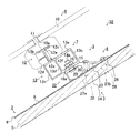
도1은 본 실시형태의 고정구조의 개략적인 구성을 나타내는 사시도이다.
도2는 고정구조를 지붕구조부재에 설치한 상태를 나타내는 측방으로부터 본 설명도이다.
도3은 고정구조의 개략적인 구성을 나타내는 분해 사시도이다.
도4는 스페이서 부재의 구성을 나타내는 (a)정면도, (b)평면도 및 (c)좌측면도이다.
도5는 제2고정부재의 구성을 나타내는 (a)정면도, (b)평면도 및 (c)좌측면도이다.
도6은 본 발명의 고정구조에 있어서 다른 예의 구성을 나타내는 사시도이다.1 is a perspective view showing a schematic structure of a fixing structure of the present embodiment.
Fig. 2 is an explanatory side view showing a state in which the fixing structure is provided on the roof structural member. Fig.
3 is an exploded perspective view showing a schematic structure of the fixing structure.
4 is a front view (a), a plan view (b), and a left side view of the spacer member showing the configuration of the spacer member.
5 is a front view (a), a front view (b), and a left side view of the second fixing member.
6 is a perspective view showing the structure of another example of the fixing structure of the present invention.
이하, 본 발명의 1실시형태인 고정구조(固定構造)(1)(태양전지모듈의 고정구조)에 대해서 도1 내지 도6에 의거하여 설명한다. 여기에서 도1은 본 실시형태의 고정구조(1)의 개략적인 구성을 나타내는 사시도(斜視圖)이며, 도2는 고정구조(1)를 지붕구조부재(2)에 설치한 상태를 나타내는 측방으로부터 본 설명도이며, 도3은 고정구조(1)의 개략적인 구성을 나타내는 분해 사시도이며, 도4는 스페이서 부재(spacer 部材)(3)의 구성을 나타내는 (a)정면도, (b)평면도 및 (c)좌측면도이며, 도5는 제2고정부재(4)의 구성을 나타내는 (a)정면도, (b)평면도 및 (c)좌측면도이며, 도6은 본 발명의 고정구조의 다른 예의 구성을 나타내는 사시도이다. 여기에서 본 실시형태의 고정구조(1)는, 도2 등에 나타나 있는 바와 같이 산자널이나 서까래 등의 건축구조부재(5)의 위에 지붕자재(6)를 부설해서 구축된 지붕(지붕구조부재(2))에 대하여, 제1고정부재(7) 및 제2고정부재(4)를 이용하여 지붕구조부재(2)가 경사진 구조면(構造面)(8)에 태양전지모듈(9)을 설치하는 것에 대해서 예시한다. 또 틀체(11) 등을 포함하는 태양전지모듈(9)의 구성은, 설명을 간략화하기 위해 필요에 따라서 도면에 나타내는 것을 생략하고 있다.Hereinafter, a stationary structure (stationary structure) 1 (stationary structure of a solar cell module) according to an embodiment of the present invention will be described with reference to Figs. 1 to 6. Fig. 1 is a perspective view showing a schematic structure of a fixing
본 실시형태의 고정구조(1)는, 도1 등에 나타나 있는 바와 같이 사각형모양으로 형성된 태양전지모듈(9)과, 태양전지모듈(9)의 마룻대측 및 처마측의 각각의 틀체(11)를 지지하는 복수의 제1고정부재(7)와, 지붕구조부재(2)에 고정되는 제2고정부재(4)와, 제1고정부재(7) 및 제2고정부재(4) 사이에 다단(多段)으로 적층(積層)하여 삽입해서 설치되는 복수의 스페이서 부재(3)를 구비하여 주로 구성되어 있다.The
태양전지모듈(9)은, 평면에서 볼 때에 있어서 대략 사각형모양으로 되어, 태양광을 받음으로써 발전하는 태양전지셀(도면에는 나타내지 않는다)을 구비하는 태양전지패널(太陽電池panel)(10)과, 태양전지패널(10)의 패널 외주(panel 外周)(10a)를 지지하는 틀체(11)를 구비하여 주로 구성되어 있다. 여기에서 틀체(11)는, 후술하는 제1고정부재(7)의 틀체 접속부(12)와 결합가능하게 형성되어 있다. 또 태양전지모듈(9) 및 그 틀체(11) 등의 구성에 대해서는 종래부터 알려진 것을 이용하는 것이 가능하며, 여기에서는 형상 등의 상세한 설명은 생략하는 것으로 한다.The solar cell module 9 includes a solar cell panel (solar cell panel) 10 having a substantially rectangular shape when viewed in a plan view and having a solar cell (not shown) that generates power by receiving sunlight, And a
제1고정부재(7)는, 도2 등에 나타나 있는 바와 같이 태양전지모듈(9)의 틀체(11)를 지지하는 틀체 접속부(12)와, 당해 틀체 접속부(12)의 하측위치에 설치되고 제2고정부재(4)와 복수의 스페이서 부재(3)를 통하여 고정되는 대좌부(臺座部)(13)를 구비하여 주로 구성되어 있다. 또한 구체적으로 설명하면 대좌부(13)는, 측방에서 볼 때에 있어서 단면 사각형모양의 사각통모양을 하고, 대좌부 상면부(13a), 대좌부 저면부(13b), 대좌부 상면부(13a) 및 대좌부 저면부(13b)의 양단 상호간을 접속하는 한 쌍의 대좌부 측면부(13c) 및 대좌부 상면부(13a) 및 대좌부 저면부(13b)의 중앙부분을 연결하는 보강 다리부(13d)를 구비하여 구성되어 있다. 또 보강 다리부(13d)에 의하여 구획된 마룻대측의 대좌부 저면부(13b)에는 후술하는 제2고정부재(4)와의 체결고정(締結固定)에 사용되는 체결고정볼트(14)의 볼트축(bolt軸)(14a)을 삽입가능한 볼트 구멍(15)이 형성되어 있다. 즉 보강 다리부(13d)에 의하여 구획된 마룻대측의 공간(볼트 구멍(15)의 상방)에 체결고정용의 너트(nut)(16)를 삽입할 수 있도록 되어 있다. 여기에서 체결고정볼트(14) 및 너트(16)가 본 발명에 있어서의 체결고정부에 상당한다.The first fixing member 7 includes a
한편 틀체 접속부(12)는, 상기 대좌부(13)의 보강 다리부(13d)에 의하여 구획된 처마측 위치에 설치되고, 대좌부 상면부(13a)로부터 연직방향으로 세워서 설치된 세움 설치부(12a)와, 세움 설치부(12a)의 선단으로부터 처마측 및 마룻대측에 각각 수평방향으로 연장된 한 쌍의 수평연장부(12b, 12c)와, 처마측의 수평연장부(12b) 및 대좌부 상면부(13a) 사이이며, 또한 세움 설치부(12a)의 중간위치로부터 처마측과 수평방향으로 돌출하도록 설치되어 선단이 갈고리모양으로 형성된 돌출부(12d)와, 마룻대측의 수평연장부(12c)의 하면 및 대좌부(13)의 대좌부 상면부(13a)가 서로 마주 대하는 위치로부터 각각 돌출된 한 쌍의 틀체결합용 돌출부(12e, 12f)를 구비하여 주로 구성되어 있다. 당해 구성을 채용함으로써 태양전지모듈(9)의 처마측 및 마룻대측의 틀체(11)를 각각 결합하여 지지할 수 있다. 여기에서 제1고정부재(7)는, 알루미늄 등의 금속제의 소재를 이용하여 구성되어 있다. 또한 제1고정부재(7)는, 태양전지모듈(9)의 틀체(11)의 길이방향(도2에 있어서의 지면(紙面)의 깊이방향에 상당)을 따라 복수 개가 설치되어 있다.On the other hand, the
또한 스페이서 부재(3)는, 도4 등에 주로 나타나 있는 바와 같이 대략 사각형모양의 평판모양을 하여 구성되고, 처마측 스페이서변(3a)으로부터 중앙부를 향하여 파여진 반타원형모양의 노치부(notch部)(17)를 구비하고 있다. 이러한 노치부(17)의 파여진 폭은, 상기한 체결고정볼트(14)의 볼트축(14a)의 축지름과 대략 일치하도록 설정되어 있다. 또한 스페이서 부재(3)의 두께는, 본 실시형태의 고정구조(1)에서는 약 3mm로 설정되어 4개의 스페이서 부재(3)를 사용하고 있다. 한편 스페이서 부재(3)의 마룻대측 스페이서변(3b)의 변 상단(邊 上端)(3c)은, 모서리부를 4각형모양으로 파내어 계단모양으로 형성된 단차부(18)가 형성되어 있다. 또한 마룻대측 스페이서변(3b)의 변 하단(邊 下端)(3d)은, 상기의 단차부(18)의 계단모양의 형상과 일치하도록 스페이서 부재(3)의 마룻대측 스페이서변(3b)으로부터 하방으로 돌출된 걸기부(19)가 형성되어 있다. 이에 따라 도2에 나타나 있는 바와 같이 복수 개(여기에서는 4개)의 스페이서 부재(3)를 다단으로 적층시켰을 경우에, 상하의 스페이서 부재(3)의 각각의 단차부(18) 및 걸기부(19)가 서로 결합하여 스페이서 부재(3)의 상면 및 하면이 틈새없이 밀착하여 접착하고, 또한 스페이서 부재(3)의 마룻대측 스페이서변(3b)의 변 위치가 상하방향으로 일치된 상태에서 적층되게 된다. 또 적층된 최상단에 위치하는 스페이서 부재(3)가 제1고정부재(7)의 대좌부 저면부(13b)와 접촉하고, 한편 최하단의 스페이서 부재(3)가 후술하는 제2고정부재(4)의 재치부(載置部)(20)의 재치면(20a)과 접촉하게 된다. 접촉하는 스페이서 부재(3)의 상면 및 하면의 접촉면적은, 보강 다리부(13d)에 의하여 구획된 마룻대측의 대좌부 저면부(13b)의 면적 및 재치부(20)의 재치면(20a)의 면적과 각각 대략 일치하도록 형성되어 있다.The
한편 제2고정부재(4)는, 도2 등에 나타나 있는 바와 같이 상기의 스페이서 부재(3)를 통하여 제1고정부재(7)의 대좌부(13)를 재치하는 재치면(20a)을 구비하는 재치부(20) 및 재치부(20)의 처마측 재치변(20b)으로부터 직교방향(直交方向)으로 곡절(曲折)되어 재치부(20)를 지붕구조부재(2)의 구조면(8)으로부터 소정의 높이로 지지하기 위한 수직다리부(21)를 구비해 제1고정부재(7)를 하방으로부터 지지하는 재치연결부(載置連結部)(22)와, 재치부(20)의 마룻대측 재치변(20c)으로부터 구조면을 향하여 경사방향으로 곡절되어 연장된 경사부(23) 및 경사부(23)와 구조면(8) 사이에 설치되어 경사부(23)의 경사면(23a)으로부터 직교방향으로 구조면(8)을 향하여 돌출하도록 설치된 경사다리부(24)를 구비하는 경사연결부(傾斜連結部)(25)와, 경사부(23)의 마룻대측 경사변(23b)으로부터 구조면(8)과 맞게 경사방향으로 곡절하여 연장되어 구조면(8)과 접촉하는 접촉면(26a)을 구비하는 접촉부(當接部)(26)를 구비하는 것으로 주로 구성되어 있다. 여기에서 제2고정부재(4)의 재치연결부(22), 경사연결부(25) 및 접촉부(26)는, 제1고정부재(7)와 마찬가지로 알루미늄 등의 금속제의 소재로 구성되어 일체적으로 형성되어 있다. 이러한 제2고정부재(4)는, 경사부(23)로부터 경사다리부(24)를 관통하도록 형성된 경사고정 나사구멍(27a)과, 접촉부(26)에 관통하도록 형성된 접촉고정 나사구멍(27b)을 구비하고, 이러한 나사구멍(27a) 및 고정용 나사(28)를 이용하여 지붕구조부재(2)에 고정된다. 또한 제2고정부재(4)는, 재치연결부(22)의 재치부(20)의 재치면(20a)을 관통하도록 장공형상(長孔形狀)의 장공부(29)가 형성되어 있다. 또 장공부(29)는 대략 타원형상을 하고, 긴 원의 방향이 지붕구조부재(2)의 처마측 및 마룻대측을 연결한 방향(도5(b)에 있어서의 지면의 상하방향에 상당)과 일치하도록 되어 있다.On the other hand, the second fixing
또한 제2고정부재(4)는, 그 이외의 구성으로서 재치연결부(22)의 재치부(20)의 마룻대측 재치변(20c)에, 스페이서 부재(3)의 걸기부(19)의 형상과 일치하는 제2고정단차부(第2固定段差部)(30)가 형성되어 있다. 이러한 제2고정단차부(30)에 스페이서 부재(3)의 걸기부(19)를 걸침으로써 스페이서 부재(3)를 제2고정부재(4)에 용이하게 걸어둘 수 있다. 또 스페이서 부재(3)는, 마룻대측 스페이서변(3b)을 따라 상기 단차부(18) 및 걸기부(19)가 형성되어 있으며, 도5에 나타나 있는 바와 같이 제2고정단차부(30)도 제2고정부재(4)의 폭방향(도5(b) 등에 있어서의 지면의 좌우방향에 상당)을 따라 형성되어 있다. 그 때문에 상기 걸어두기에 의하여 스페이서 부재(3)는, 체결고정볼트(14)의 볼트축(14a)을 따라 회전하는 것이 제한된다. 또 재치연결부(22)의 수직다리부(21) 및 경사연결부(25)의 경사 다리부(24)는, 각각 구조면(8)과의 접촉면적을 늘리기 위해서 수평방향으로 연장된 다리돌출부(31)가 형성되어 있다. 여기에서 다리돌출부(31)의 다리면(31a)과 접촉부(26)의 접촉면(26a)이 일치하도록 형성되어 있다.The
다음에 본 실시형태의 고정구조(1)에 있어서의 태양전지모듈(9)의 설치 및 고정의 일례에 대해서 설명한다. 우선 처마측에 배치하는 제2고정부재(4)를 소정의 간격으로 가로방향(도2에 있어서의 지면의 깊이방향)을 따라 복수배치하여 지붕구조부재(2)에 고정한다. 이때에 제2고정부재(4)는, 처마측으로부터 마룻대측을 따라서 재치연결부(22)의 수직다리부(21)의 다리돌출부(31)의 다리면(31a), 경사연결부(25)의 경사다리부(24)의 다리돌출부(31)의 다리면(31a) 및 접촉부(26)의 접촉면(26a)의 세개의 부위에서, 지붕구조부재(2)의 구조면(8)과 각각 접촉하고 있다. 그리고 경사다리부(24) 및 접촉부(26)에 각각 형성된 나사구멍(27a, 27b)에 고정용 나사(28)를 상방으로부터 삽입하고, 지붕구조부재(2)에 고정용 나사(28)의 선단을 삽입하도록 해서 고정한다. 그 결과, 제2고정부재(4)가 경사진 구조면(8)을 따른 상태에서 고정된다. 이때에 나사구멍(27a, 27b)의 천공방향(穿孔方向)이 서로 멀어지고 있다(도2 등 참조). 그 결과, 이러한 나사구멍(27a, 27b)에 삽입되어 지붕구조부재(2)와 고정되는 2개의 고정용 나사(28)도, 측방에서 볼 때에 있어서 나사 선단을 향하여 멀어지고 있다. 즉 마룻대측에 배치된 일방(一方)의 고정용 나사(28)는 접촉부(26)의 접촉면(26a)과 직교하고, 또한 지붕구조부재(2)의 구조면(8)에 대하여도 직교하도록 고정되고, 처마측에 배치된 타방(他方)의 고정용 나사(28)는 경사다리부(24)에 형성된 나사구멍(27a)을 따라 경사방향, 구체적으로 설명하면 고정용 나사(28)의 두부(頭部)에 대하여 나사 선단을 더 처마측을 향한 상태에서 고정된다. 그 결과, 마룻대측으로부터 처마측을 향하여 강한 하중(荷重)을 가한 경우에도, 한 쌍의 고정용 나사(28)가 구조면(8)에 대하여 각각 직교하는 방향으로 고정되었을 경우와 비교하여, 내하중 성능(耐荷重 性能)을 향상시킬 수 있다. 그 결과, 지붕위에 설치되는 태양전지모듈(9) 등을 충분하게 지탱하는 것이 가능하게 된다. 특히 지붕위에 가로, 세로방향으로 복수 개 설치되는 태양전지모듈(9)의 경우에, 처마측의 최하단에 설치된 제2고정부재(4)에는 큰 하중이 가해지게 된다. 본 실시형태의 고정구조(1)에 의하면, 상기 나사구멍(27a, 27b) 및 한 쌍의 고정용 나사(28)의 배치에 의하여, 이러한 상황에 충분하게 대응할 수 있다.Next, an example of mounting and fixing of the solar cell module 9 in the fixed
제2고정부재(4)가 지붕구조부재(2)에 고정된 후에, 제2고정부재(4)의 재치부(20)의 재치면(20a)에 스페이서 부재(3)를 적층하여 설치한다. 구체적으로 설명하면 사각형모양의 스페이서 부재의 마룻대측 스페이서변(3b)에 형성되고, 하방으로 돌출하도록 갈고리 모양(또는 L자모양)으로 형성된 걸기부(19)를 제2고정부재(4)의 제2고정단차부(30)에 걸어둔다. 이때에 상기한 바와 같이 제2고정부재(4) 자체는, 지붕구조부재(2)의 구조면(8)을 따라 경사져 있다. 따라서 걸기부(19)가 제2고정단차부(30)에 걸어진 상태인 스페이서 부재(3)는, 자체 중량에 의하여 처마측으로 낙하하려는 움직임이 걸기부(19) 및 제2고정단차부(30)에 의하여 제한되어, 걸린 상태를 유지할 수 있다. 또한 도4 및 도5에 나타나 있는 바와 같이 걸기부(19) 및 제2고정단차부(30)는, 각각 스페이서 부재(3) 및 제2고정부재(4)의 각 변을 따라 설치되어 있기 때문에, 스페이서 부재(3)의 길이방향(도2에 있어서의 지면의 깊이방향)에 대한 회전이 제한된다. 이에 따라 걸어두기 상태가 안정된 것이 된다. 특히 후술하는 체결고정볼트(14)의 볼트축(14a)을 따라 스페이서 부재(3)가 회전하려는 움직임을 제한할 수 있다.The
제2고정부재(4)에 대한 스페이서 부재(3)의 설치와 마찬가지로, 설치된 최하위치의 스페이서 부재(3)의 위에 그 이외의 스페이서 부재(3)를 적층한다. 이때에 스페이서 부재(3)의 단차부(18)와 걸기부(19)가 상호 일치하도록 형성되어 있기 때문에, 도2 등에 나타나 있는 바와 같이 제2고정부재(4)의 재치부(20)의 재치면(20a)에 4개의 스페이서 부재(3)가 다단으로 적층된 상태를 유지할 수 있다. 이때에 개개의 스페이서 부재(3)에 형성된 노치부(17)의 위치가 일치되도록 가로방향(도2에 있어서의 지면의 깊이방향에 상당)의 조정이 이루어진다.
그리고 제2고정부재(4)의 재치부(20)의 재치면(20a)의 이면(裏面)측의 공간으로부터 체결고정볼트(14)의 볼트축(14a)이 재치부(20) 및 스페이서 부재(3)를 관통하도록 형성한다. 여기에서 재치부(20)에는, 볼트축(14a)을 삽입가능한 장공형상의 장공부(29)가 형성되고, 한편 스페이서 부재(3)에는, 처마측 스페이서변(3a)으로부터 파여진 노치부(17)가 형성되어 있다. 그 때문에 상기한 체결고정볼트(14)의 설치가 가능해 진다. 그리고 최상단에 위치하는 스페이서 부재(3)의 상면에 제1고정부재(7)의 대좌부(13)의 대좌부 저면부(13b)를 재치한다. 이때에 체결고정볼트(14)의 볼트축(14a)과 대좌부 저면부(13b)를 관통하여 형성된 볼트 구멍(15)의 위치를 맞추어, 볼트 구멍(15)으로부터 볼트축(14a)의 선단이 돌출된 상태로 한다. 그리고 볼트축(14a)의 선단에 와셔(16a)를 통하여 너트(16)를 부착하여 나사결합시킴으로써, 체결고정볼트(14)의 볼트 두부(도면에는 나타내지 않는다) 및 너트(16) 사이에, 재치연결부(22)의 재치부(20), 4개의 스페이서 부재(3) 및 대좌부 저면부(13b)를 사이에 둔 상태에서 고정할 수 있다. 이에 따라 제1고정부재(7) 및 제2고정부재(4)의 고정이 완료된다. 이때에 제1고정부재(7)는, 보강 다리부(13d)에 의하여 구획되어 볼트 구멍(15)이 형성된 마룻대측의 대좌부 저면부(13b)에 대하여, 틀체 접속부(12)가 설치된 대좌부 저면부(13b)가 처마측에 위치하도록 조정된다. 여기에서 본 실시형태의 고정구조(1)에 있어서 두께 3mm의 스페이서 부재(3)가 사용되어, 전체로서 1.2cm의 높이조정을 한 것을 나타내고 있다. 이러한 스페이서 부재(3)의 사용개수 등은, 태양전지모듈(9)을 설치하는 지붕구조부재(2)의 요철형상에 따라 적절하게 변경할 수 있다.The
여기에서 제1고정부재(7) 및 제2고정부재(4)를 고정하는 체결고정볼트(14) 및 너트(16)(체결고정부에 상당)에 의한 체결을 당초에 느슨해진 상태로 하여, 재치부(20)에 형성된 장공부(29)를 따라 볼트축(14a)의 위치를 처마측 또는 마룻대측 방향으로 이동시킬 수 있다. 이에 따라 제2고정부재(4)에 대한 제1고정부재(7)의 고정위치(상대적 위치관계)를 소정의 범위에서 자유자재로 조정할 수 있다. 이에 따라 제1고정부재(7)에 의하여 지지되는 태양전지모듈(9)의 설치위치를 처마측 방향 또는 마룻대측 방향을 향하여 미세조정을 도모할 수 있다. 이에 따라 지붕구조부재(2)에 대하여 가로, 세로방향으로 복수배열되는 태양전지모듈(9)의 부착위치 등을 맞추어 정렬시킬 수 있다. 또 이 조정은, 태양전지모듈(9)을 제1고정부재(7)에 고정한 후에도 가능하게 된다.The
제2고정부재(4)에 제1고정부재(7)가 고정된 후에, 제1고정부재(7)의 틀체 접속부(12)에 태양전지모듈(9)의 틀체(11)를 부착한다. 이러한 설치의 상세한 것은 종래부터 주지된 것이기 때문에 상세한 설명은 생략한다. 또 본 실시형태의 고정구조(1)에 있어서 제2고정부재(4)의 경사연결부(25)는, 경사면(23a)을 구비하는 경사부(23)가, 틀체 접속부(12)가 설치된 제1고정부재(7)의 설치위치보다 마룻대측에 위치해서 설치되어 있다. 그 때문에 태양전지모듈(9)을 제1고정부재(7)에 고정할 때에, 처음에 마룻대측으로부터 처마측을 향하여 태양전지모듈(9)을 이동시키고, 이러한 경사면(23a)을 이용하여 고정작업을 편하게 할 수 있다. 구체적으로 설명하면 태양전지모듈(9)의 설치시에 상기 경사면(23a)과 태양전지모듈(9)의 처마측의 틀체(11)의 일부를 접촉시켜, 상기 경사면(23a)을 따라 미끄러지게 하면서 틀체(11)를 틀체 접속부(12)까지 인도하는 것이 가능하게 된다. 여기에서 일반적인 고정설치작업의 경우에 지붕구조부재(2)의 위는 요철이 많이 존재하여, 예를 들면 구조면(8)상을 미끄러지게 하면서 태양전지모듈(9)을 원하는 위치까지 이동시키기는 어려웠다. 그 때문에 복수의 작업자가 태양전지모듈(9)을 파지(把持)하여 완전하게 들어올린 상태에서 틀체 접속부(12)까지 이동하고 있었다. 이에 대하여 본 실시형태의 고정구조(1)의 경우에, 경사면(23a)을 따라 태양전지모듈(9)을 미끄러지게 함으로써 제1고정부재(7)의 근방까지 편하게 태양전지모듈(9)을 가까이할 수 있고, 경사부(23)의 근처에서 태양전지모듈(9)을 들어올릴 수 있다. 이에 따라 태양전지모듈(9)의 설치작업을 용이하게 하여 작업자의 부담을 경감시킬 수 있다. 또 태양전지모듈(9)의 마룻대측의 틀체(11)에 대하여도, 마찬가지로 제2고정부재(4) 및 제1고정부재(7)를 사용한 지지가 이루어진다. 이에 따라 처마측 및 마룻대측에 설치된 제1고정부재(7) 및 제2고정부재(4) 사이에, 태양전지모듈(9)이 구조면(8)으로부터 소정의 높이로 뜬 상태에서 지지된다. 또 지붕위에 설치한 후의 태양전지모듈(9)에 대한 전기적인 작업 등에 관해서는 설명을 생략한다.After the first fixing member 7 is fixed to the second fixing
이상, 설명한 바와 같이 본 실시형태의 고정구조(1)에 의하면, 제1고정부재(7)가 지붕구조부재(2)에 제2고정부재(4) 및 스페이서 부재(3)를 통하여 고정됨으로써, 태양전지모듈(9)의 교환작업시에 지붕구조부재(2)를 직접 손상시키는 일이 없다. 즉 상기 교환작업시는, 제1고정부재(7) 및 제2고정부재(4)를 체결한 고정 볼트(14) 및 너트(16)의 체결고정부에 의한 고정을 해제하고, 제2고정부재(4)로부터 제1고정부재(7)를 떼어냄으로써 태양전지모듈(9)을 지붕위로부터 제거할 수 있다. 그 결과로 교환작업마다 지붕구조부재(2)에 고정용 나사(28)에 의한 구멍이 뚫리는 일이 없다. 그 결과, 지붕구조부재(2)의 미관(美觀)을 해치는 일이 없고 또한 빗물 등이 침입할 가능성을 억제할 수 있다. 또한 제1고정부재(7) 및 제2고정부재(4) 사이에 스페이서 부재(3)를 삽입하여 설치함으로써, 설치하는 지붕구조부재(2)의 구조면의 요철형상에 따라 필요한 조정을 하여, 태양전지모듈(9)의 설치높이를 일정하게 갖출 수 있다. 또한 이러한 스페이서 부재(3)는, 다단으로 적층할 수 있으며, 단차부(18) 및 걸기부(19)에 의하여 처마측 스페이서변(3a) 및 마룻대측 스페이서변(3b)을 갖춘 상태에서 적층할 수 있으며, 설치시에 있어서의 미관을 해치는 일이 없다. 또한 이러한 단차부(18) 등에 의하여 볼트축(14a) 주위의 스페이서 부재(3)의 회전을 제한할 수 있어, 제1고정부재(7) 및 제2고정부재(4) 사이에 확실하게 삽입하여 설치된 상태를 유지할 수 있다. 또한 경사연결부(25)의 경사부(23)의 경사면(23a)을 이용함으로써 태양전지모듈(9)의 설치작업을 용이하게 하거나, 재치부(20)의 장공부(29)를 이용함으로써 태양전지모듈(9)의 위치조정을 용이하게 할 수 있다.As described above, according to the fixing
이상, 본 발명에 대해서 적합한 실시형태를 들어서 설명했지만, 본 발명은 이들 실시형태에 한정되는 것이 아니라, 이하에 나타나 있는 바와 같이 본 발명의 요지를 일탈하지 않는 범위에 있어서 다양한 개량 및 설계의 변경이 가능하다.Although the preferred embodiments of the present invention have been described above, the present invention is not limited to these embodiments. Various modifications and changes in design may be made without departing from the gist of the present invention as described below. It is possible.
즉 본 실시형태의 고정구조(1)에 있어서, 제1고정부재(7) 및 제2고정부재(4) 사이에 4개의 스페이서 부재(3)를 삽입하여 설치하는 것을 나타냈지만 이에 한정되는 것은 아니다. 설치대상인 지붕구조부재(2)의 요철형상이나 경사에 따라 임의로 설치개수를 조정할 수 있으며, 예를 들면 도6의 다른 예의 구성에 나타나 있는 바와 같이 스페이서 부재(3)를 사용하지 않는 태양전지모듈(9)의 설치구조(32)로 하는 것이더라도 상관없다. 이러한 구성을 채용함으로써 제1고정부재(7)의 대좌부 저면부(13b)와 제2고정부재(4)의 재치부(20)의 재치면(20a)이 직접 접촉하게 되어, 부품수 및 작업공수를 감소시킴으로써 작업비용의 절감화를 도모할 수 있다.That is, in the fixing
또한 본 실시형태의 고정구조(1)에 있어서 태양전지모듈(9)을 신설할 경우를 나타냈지만, 이에 한정되는 것은 아니다. 즉 태양전지모듈(9)의 설치후로부터 소정의 기간이 경과하여 태양전지모듈(9)의 유지보수작업을 하기 위해서 지붕자재(6)로부터 일단 떼어내는 경우에도, 상기의 우수한 효과를 누릴 수 있다. 이 경우에 제2고정부재(4)는 지붕구조부재(2)의 구조면(8)에 그대로 남기고, 제1고정부재(7) 및 태양전지모듈(9)만을 떼어냄으로써 태양전지모듈(9)에 대한 유지보수작업을 할 수 있다. 그리고 유지보수작업이 완료된 태양전지모듈(9)을 다시 지붕위에 설치하는 경우에는, 제2고정부재(4)의 재치연결부(22)에 형성된 장공부(29)를 이용하여 제1고정부재(7) 및 제2고정부재(4)의 마룻대측 및 처마측을 연결한 선상(線上)(세로방향)에서의 상대적인 위치관계의 조정을 용이하게 할 수 있게 되어, 지붕구조부재(2)를 손상시키는 일이 없이 유지보수작업을 용이하게 할 수 있고 또한 작업시간의 단축화를 도모할 수 있다.
In addition, although a case has been described in which the solar cell module 9 is installed in the fixing
1 ; 고정구조
2 ; 지붕구조부재
3 ; 스페이서 부재
4 ; 제2고정부재
5 ; 건축구조부재
6 ; 지붕자재
7 ; 제1고정부재
8 ; 구조면
9 ; 태양전지모듈
10 ; 태양전지패널
11 ; 틀체
12 ; 틀체 접속부
13 ; 대좌부
14 ; 고정 볼트
15 ; 볼트 구멍
16 ; 너트
17 ; 노치부
18 ; 단차부
19 ; 걸기부
20 ; 재치부
21 ; 수직다리부
22 ; 재치연결부
23 ; 경사부
24 ; 경사다리부One ; Fixed structure
2 ; Roof structural member
3; The spacer member
4 ; The second fixing member
5; Building structure member
6; Roof material
7; The first fixing member
8 ; Structural surface
9; Solar cell module
10; Solar panel
11; Frame
12; Frame connection
13; Pedestal portion
14; Fixing bolt
15; Bolt hole
16; nut
17; Notch
18; Stepped portion
19; Giving donation
20; Wit
21; Vertical leg
22; Mountable connection
23; Inclined portion
24; Inclined leg
Claims (3)
상기 틀체와 접속하는 틀체 접속부 및 상기 틀체 접속부의 하측위치에 형성된 대좌부(臺座部)를 구비하는 제1고정부재(第1固定部材)와,
상기 제1고정부재 및 상기 태양전지모듈의 설치대상인 지붕구조부재 사이에 삽입하여 설치시키는 제2고정부재를
구비하고,
상기 제2고정부재는,
상기 대좌부를 재치하는 재치면(載置面)을 구비하는 재치부 및 상기 재치부의 처마측 재치변으로부터 직교방향으로 곡절(曲折)되어 상기 재치부를 상기 지붕구조부재의 구조면으로부터 소정의 높이로 지지하는 수직다리부를 구비하고,
상기 제1고정부재와 연결되는 재치연결부(載置連結部)와,
상기 재치부의 마룻대측 재치변으로부터 경사방향으로 곡절하여 연장된 경사부 및 상기 경사부와 상기 구조면 사이를 연결하는 경사다리부를 구비하는 경사연결부(傾斜連結部)와,
상기 경사부의 마룻대측 경사변으로부터 상기 구조면을 따르도록 경사방향으로 곡절하여 연장되어 상기 구조면과 접촉하는 접촉면을 구비하는 접촉부(接觸部)를
구비하는 것을 특징으로 하는 태양전지모듈의 고정구조.
A solar cell module (solar battery module) having a rectangular solar cell panel (solar cell panel) and a frame body in contact with the outer periphery of the panel of the solar cell panel,
A first fixing member (first fixing member) having a frame connecting portion connected to the frame body and a pedestal portion formed at a lower position of the frame connecting portion,
And a second fixing member inserted and provided between the first fixing member and the roof structural member to which the solar cell module is installed
Respectively,
Wherein the second fixing member comprises:
A placement portion having a placement surface on which the pedestal portion is placed; and a support portion that is bent in a direction orthogonal to the eave side of the placement portion and supports the placement portion at a predetermined height from the structural surface of the roof structural member And a vertical leg portion
(Mounting connection portion) connected to the first fixing member,
An inclined connection portion (inclined connection portion) having an inclined portion which is elongated and bent in an oblique direction from the mount side of the placement portion and an inclined leg portion which connects the inclined portion and the structural surface,
And a contact portion extending from the slope side edge of the inclined portion in an oblique direction so as to extend along the structural surface and having a contact surface contacting the structural surface,
The solar cell module comprising:
상기 재치연결부는,
상기 재치부를 관통하고, 상기 지붕구조부재의 처마측 및 마룻대측을 연결한 지붕경사방향을 따라 신장한 장공형상(長孔形狀)의 장공부를 더 구비하고,
상기 장공부에 삽입가능한 체결고정볼트 및 상기 체결고정볼트에 체결되는 너트를 구비하고, 제2고정부재에 대한 상기 제1고정부재의 고정위치를 상기 지붕경사방향을 따라 조정하여 상기 제1고정부재 및 제2고정부재를 연결하는 체결고정부(締結固定部)를 더 구비하는 것을
특징으로 하는 태양전지모듈의 고정구조.
The method according to claim 1,
Wherein,
Further comprising an elongated slot extending through the placement portion and extending along a roof inclination direction connecting the eaves and the paddy side of the roof structural member,
And a nut fastened to the fastening bolt, wherein the fastening position of the first fastening member with respect to the second fastening member is adjusted along the roof inclination direction, And a fastening fastening portion (fastening fastening portion) for connecting the second fastening member
A fixed structure of the solar cell module.
사각형모양을 하고, 상기 대좌부 및 상기 재치부 사이에 다단(多段)으로 적층(積層)할 수 있도록 삽입하여 설치되는 스페이서 부재(spacer 部材)를 더 구비하고,
상기 스페이서 부재는,
상기 스페이서 부재의 처마측 스페이서변으로부터 상기 체결고정볼트의 볼트축을 삽입가능한 폭으로 파여된 노치부(notch部)와,
상기 스페이서 부재의 마룻대측 스페이서변의 변 상단(邊 上端)에 형성된 단차부(段差部)와,
상기 마룻대측 스페이서변의 변 하단(邊 下端)에 상기 단차부의 단차형상과 합치하도록 형성된 걸기부를
구비하고,
상기 제2고정부재는,
상기 마룻대측 재치변에 상기 걸기부의 형상과 일치하는 제2고정단차부(第2固定段差部)를 더 구비하여 구성되는 것을 특징으로 하는 태양전지모듈의 고정구조.The method according to claim 1,
Further comprising a spacer member having a rectangular shape and inserted and inserted so as to be stacked in multiple stages between the pedestal portion and the placement portion,
Wherein the spacer member comprises:
A notch portion which is formed at a width of the spacer side of the spacer member so as to allow insertion of the bolt axis of the fastening fixing bolt,
A stepped portion formed on a side upper end of the spacer side of the spacer side of the spacer member,
And a hanging portion formed at a lower end of the marginal side spacer side so as to coincide with the stepped shape of the stepped portion
Respectively,
Wherein the second fixing member comprises:
And a second fixing step portion (second fixing step difference portion) that coincides with the shape of the hooking portion on the wedge side mount side.
Applications Claiming Priority (1)
| Application Number | Priority Date | Filing Date | Title |
|---|---|---|---|
| PCT/JP2011/075205 WO2013065130A1 (en) | 2011-11-01 | 2011-11-01 | Solar cell module fixing structure |
Publications (1)
| Publication Number | Publication Date |
|---|---|
| KR20140085420A true KR20140085420A (en) | 2014-07-07 |
Family
ID=46650213
Family Applications (1)
| Application Number | Title | Priority Date | Filing Date |
|---|---|---|---|
| KR1020147005435A KR20140085420A (en) | 2011-11-01 | 2011-11-01 | Solar cell module fixing structure |
Country Status (7)
| Country | Link |
|---|---|
| US (1) | US8453394B2 (en) |
| EP (1) | EP2775065B1 (en) |
| JP (1) | JP4975893B1 (en) |
| KR (1) | KR20140085420A (en) |
| CN (1) | CN103875178B (en) |
| AU (1) | AU2011349904B2 (en) |
| WO (1) | WO2013065130A1 (en) |
Cited By (2)
| Publication number | Priority date | Publication date | Assignee | Title |
|---|---|---|---|---|
| KR101626593B1 (en) | 2015-12-15 | 2016-06-01 | 두원산업(주) | Solar cell construction installation process |
| KR101963241B1 (en) * | 2018-07-20 | 2019-03-28 | 반근영 | Easy-to-install standard solor panel fixings |
Families Citing this family (25)
| Publication number | Priority date | Publication date | Assignee | Title |
|---|---|---|---|---|
| US9447988B2 (en) | 2010-01-25 | 2016-09-20 | Rillito Rive Solar, LLC | Roof mount assembly |
| US8595996B2 (en) * | 2010-02-26 | 2013-12-03 | General Electric Company | Photovoltaic framed module array mount utilizing asymmetric rail |
| JP5501125B2 (en) * | 2010-07-06 | 2014-05-21 | 株式会社屋根技術研究所 | Fixed member |
| US8776454B2 (en) * | 2011-04-05 | 2014-07-15 | Michael Zuritis | Solar array support structure, mounting rail and method of installation thereof |
| US20130167472A1 (en) * | 2012-01-03 | 2013-07-04 | Robert L. Jenkins | Photovoltaic Roofing Elements And Photovoltaic Roofing Systems |
| JP5963463B2 (en) * | 2012-02-02 | 2016-08-03 | シャープ株式会社 | Solar cell module installation structure, solar cell module installation method, solar cell module installation bar, and solar power generation system |
| US20150222220A1 (en) * | 2012-05-14 | 2015-08-06 | Mika Brian Laitila | Aerodynamic and footing design for solar panel racking systems |
| US9973142B2 (en) | 2013-03-06 | 2018-05-15 | Vermont Slate and Copper Services, Inc. | Snow fence for a solar panel |
| JP6124682B2 (en) * | 2013-05-20 | 2017-05-10 | 三菱電機ビルテクノサービス株式会社 | Solar panel mounting jig |
| US11575343B2 (en) * | 2013-12-13 | 2023-02-07 | Quick Mount PV | Waterproofing mounting system for attaching solar modules to a roof |
| JP6283239B2 (en) * | 2014-03-11 | 2018-02-21 | 積水化学工業株式会社 | Fixing structure and method of solar energy collecting panel |
| EP3128098B1 (en) * | 2014-03-31 | 2018-12-26 | Panasonic Intellectual Property Management Co., Ltd. | Solar cell apparatus |
| US9985575B2 (en) * | 2014-04-07 | 2018-05-29 | Rillito River Solar, Llc | Height adjustment bracket for roof applications |
| US9431953B2 (en) | 2014-10-31 | 2016-08-30 | Rillito River Solar, Llc | Height adjustment bracket for roof applications |
| JP6505989B2 (en) * | 2014-07-08 | 2019-04-24 | ケイミュー株式会社 | Pedestal with roof |
| US9376812B2 (en) * | 2014-08-19 | 2016-06-28 | Charles Porter | Ceiling panel mounting system |
| US9670672B2 (en) * | 2014-12-03 | 2017-06-06 | Aleksandar Stevanov | Roof panel system |
| US9708812B2 (en) * | 2015-08-17 | 2017-07-18 | Stewart P. Jeske | Pour stop anchor apparatus and system |
| JP6749798B2 (en) * | 2016-06-27 | 2020-09-02 | ソーラーフロンティア株式会社 | Fixture for panel array |
| US10469023B2 (en) | 2016-09-12 | 2019-11-05 | EcoFasten Solar, LLC | Roof mounting system |
| CA3036341C (en) * | 2016-09-29 | 2020-11-17 | Yanegijutsukenkyujo Co., Ltd. | Fixing structure of solar cell module |
| JP6910648B2 (en) | 2017-12-18 | 2021-07-28 | 株式会社屋根技術研究所 | Fixed structure and fixed unit of solar panel |
| US10490682B2 (en) | 2018-03-14 | 2019-11-26 | National Mechanical Group Corp. | Frame-less encapsulated photo-voltaic solar panel supporting solar cell modules encapsulated within multiple layers of optically-transparent epoxy-resin materials |
| US11223320B2 (en) * | 2019-03-12 | 2022-01-11 | Chandramouli Vaidyanathan | Solar panel flat roof mounting apparatus and method |
| EP4276382A1 (en) * | 2022-05-09 | 2023-11-15 | S:FLEX GmbH Hamburg | Mounting element, insertion profile and mounting system |
Family Cites Families (11)
| Publication number | Priority date | Publication date | Assignee | Title |
|---|---|---|---|---|
| US4471584A (en) * | 1982-02-24 | 1984-09-18 | Ibg International, Inc. | Unitized skylight structure |
| US4557081A (en) * | 1982-11-01 | 1985-12-10 | Kelly Thomas L | Roofing structure with hermetically sealed panels |
| US5740647A (en) * | 1995-06-01 | 1998-04-21 | Kelly; Thomas L. | Bulit-up roof (BUR) or modified roof assembly system |
| JP2907326B2 (en) * | 1996-03-22 | 1999-06-21 | 元旦ビューティ工業株式会社 | Side-roof exterior structure |
| JP4684874B2 (en) * | 2005-12-13 | 2011-05-18 | 株式会社屋根技術研究所 | Solar cell module frame |
| DE102008009608A1 (en) * | 2008-02-18 | 2009-10-15 | Niemetz Metall Gmbh | Planar element and clamping device combination, has planar element including profile rib for clamping device, where profile rib is formed with constrictions that oppose one another, and constrictions form undercuts for clamping device |
| EP2187147A1 (en) * | 2008-11-14 | 2010-05-19 | Energiebüro AG | Roof structure with an arrangement of solar panels |
| US7963081B2 (en) * | 2008-12-17 | 2011-06-21 | Garland Industries, Inc. | Roofing system |
| WO2011071489A1 (en) * | 2009-12-08 | 2011-06-16 | Twesme Edward N | Mounting system for photovoltaic module |
| WO2011077538A1 (en) * | 2009-12-25 | 2011-06-30 | 株式会社屋根技術研究所 | Auxiliary members |
| US8661747B2 (en) * | 2010-07-23 | 2014-03-04 | Kristian Eide | Solar panel racking system |
-
2011
- 2011-11-01 CN CN201180073940.8A patent/CN103875178B/en not_active Expired - Fee Related
- 2011-11-01 WO PCT/JP2011/075205 patent/WO2013065130A1/en active Application Filing
- 2011-11-01 JP JP2012504945A patent/JP4975893B1/en active Active
- 2011-11-01 KR KR1020147005435A patent/KR20140085420A/en not_active Application Discontinuation
- 2011-11-01 EP EP11855240.5A patent/EP2775065B1/en not_active Not-in-force
- 2011-11-01 AU AU2011349904A patent/AU2011349904B2/en not_active Ceased
-
2012
- 2012-07-06 US US13/543,030 patent/US8453394B2/en active Active
Cited By (2)
| Publication number | Priority date | Publication date | Assignee | Title |
|---|---|---|---|---|
| KR101626593B1 (en) | 2015-12-15 | 2016-06-01 | 두원산업(주) | Solar cell construction installation process |
| KR101963241B1 (en) * | 2018-07-20 | 2019-03-28 | 반근영 | Easy-to-install standard solor panel fixings |
Also Published As
| Publication number | Publication date |
|---|---|
| US20130104471A1 (en) | 2013-05-02 |
| CN103875178B (en) | 2016-10-12 |
| US8453394B2 (en) | 2013-06-04 |
| EP2775065A1 (en) | 2014-09-10 |
| EP2775065B1 (en) | 2018-01-10 |
| AU2011349904A1 (en) | 2013-05-16 |
| EP2775065A4 (en) | 2015-07-29 |
| AU2011349904B2 (en) | 2015-02-26 |
| WO2013065130A1 (en) | 2013-05-10 |
| JP4975893B1 (en) | 2012-07-11 |
| JPWO2013065130A1 (en) | 2015-04-02 |
| CN103875178A (en) | 2014-06-18 |
Similar Documents
| Publication | Publication Date | Title |
|---|---|---|
| KR20140085420A (en) | Solar cell module fixing structure | |
| US10365017B2 (en) | Self-adjusting end clamp | |
| US9780719B2 (en) | East-west photovoltaic array with spaced apart photovoltaic modules for improved aerodynamic efficiency | |
| TW200818524A (en) | Fixing structure of solar cell module | |
| JP5869331B2 (en) | Solar panel mounting method | |
| JP6351514B2 (en) | Fixing device for solar cell module | |
| JP5891109B2 (en) | Solar cell module fixing structure and solar cell module fixing method | |
| JP3194299U (en) | Support panel for solar panel | |
| JP5915986B2 (en) | Support structure for solar panels | |
| JP2004116240A (en) | Sunlight utilizing device | |
| JP3185161U (en) | Mounting structure for solar panel mount | |
| JP2001234619A (en) | Solar battery roof and snow guard structure of solar battery roof | |
| JP5686771B2 (en) | Solar cell module fixing structure and solar cell module fixing method | |
| JP2011106203A (en) | Mounting base of outdoor structure | |
| JP3202583U (en) | Support structure for photovoltaic panels | |
| JP6192453B2 (en) | Roof structure, solar cell module fixture, solar cell module mounting structure, and solar cell module mounting method | |
| JP2012127079A (en) | Auxiliary rafter fixing metal fitting and equipment fixing device | |
| JP2017150183A (en) | Installation stand of solar battery panel, fixture used therefor and installation method thereof | |
| JP7161311B2 (en) | Panel mounting structures, fixtures for panels, and fixture installation methods | |
| JP6023473B2 (en) | Roof surface installation structure of functional members | |
| JP5726137B2 (en) | Support frame and solar cell module | |
| JP5522754B2 (en) | Mounting structure for exterior structure and installation device | |
| JP2014001571A (en) | Tile-shaped support device | |
| KR20110131349A (en) | Installation method of solar sell module | |
| JP2014129713A (en) | Solar panel installation structure |
Legal Events
| Date | Code | Title | Description |
|---|---|---|---|
| WITN | Application deemed withdrawn, e.g. because no request for examination was filed or no examination fee was paid |