JP5386434B2 - Construction machinery - Google Patents
Construction machinery Download PDFInfo
- Publication number
- JP5386434B2 JP5386434B2 JP2010113393A JP2010113393A JP5386434B2 JP 5386434 B2 JP5386434 B2 JP 5386434B2 JP 2010113393 A JP2010113393 A JP 2010113393A JP 2010113393 A JP2010113393 A JP 2010113393A JP 5386434 B2 JP5386434 B2 JP 5386434B2
- Authority
- JP
- Japan
- Prior art keywords
- muffler
- opening
- bracket
- vehicle body
- construction machine
- Prior art date
- Legal status (The legal status is an assumption and is not a legal conclusion. Google has not performed a legal analysis and makes no representation as to the accuracy of the status listed.)
- Active
Links
Images


Description
本発明は、エンジンを覆う車体カバーの下方に設けられ、エンジンの排気音を消音するマフラを備えた油圧ショベル等の建設機械に関する。 The present invention relates to a construction machine such as a hydraulic excavator that is provided below a vehicle body cover that covers an engine and includes a muffler that muffles exhaust noise of the engine.
従来より、油圧ショベル等の建設機械は、エンジンを覆う車体カバーと、エンジンルームの内部に設けられた油圧ポンプと、車体カバーの下方にブラケットを介して設けられ、エンジンの排気音を消音するマフラとを備えている。このマフラはエンジンから排出される排気ガスの熱等によって高温になるので、何らかの原因で油圧ショベル等の油圧機器が故障又は破損してエンジンルーム内に油が飛散した場合には、問題となる。 Conventionally, a construction machine such as a hydraulic excavator has been provided with a vehicle body cover that covers an engine, a hydraulic pump provided inside the engine room, and a muffler that is provided below the vehicle body cover via a bracket to mute the exhaust sound of the engine. And. Since this muffler becomes high temperature due to the heat of the exhaust gas discharged from the engine or the like, it becomes a problem when hydraulic equipment such as a hydraulic excavator breaks down or breaks down for some reason and oil scatters in the engine room.
そこで、故障又は破損した油圧機器の油がマフラ方向へ飛散することを防止するために、車体に設けられたエンジン室、すなわちエンジンルーム内に設置され、エンジン及びエンジンにより駆動される油圧ポンプ等の油圧機器と、エンジンルーム内の上部に設置され、エンジンの排気音を消音するマフラとを備え、このマフラを、エンジンや油圧ポンプにブラケットを介して取り付けると共に、ブラケットに、金属板により一体成形された遮蔽板、すなわち仕切カバーを、マフラと油圧機器類の間を遮蔽するように取り付けた建設機械の遮蔽装置が提案されている(例えば、特許文献1参照)。 Therefore, in order to prevent the oil of the failed or damaged hydraulic equipment from splashing in the direction of the muffler, the engine room provided in the vehicle body, that is, the engine room and the hydraulic pump driven by the engine, etc. It is equipped with hydraulic equipment and a muffler installed in the upper part of the engine room to mute the exhaust sound of the engine. This muffler is attached to the engine and hydraulic pump via a bracket, and is integrally formed with the bracket by a metal plate. There has been proposed a shielding device for a construction machine in which a shielding plate, that is, a partition cover, is attached so as to shield between a muffler and hydraulic equipment (for example, see Patent Document 1).
ここで、特許文献1に開示された建設機械の遮蔽装置では、油圧ポンプから飛散した油がマフラに付着しないようにマフラと油圧ポンプとの間に仕切カバーが設けられているので、マフラの周囲が車体カバー、ブラケット、及び仕切カバーによって覆われている。従って、建設機械の作業によってエンジンルーム内に生じた塵埃の逃げ場があまりなく、塵埃がマフラ及びマフラの周辺に堆積することが問題となっている。特に、マフラと、マフラを支持しているブラケットとの間の隙間に塵埃が溜まり易く、マフラ及びマフラの周辺を定期的に清掃する必要がある。しかしながら、上述したようにマフラの周囲は車体カバー、ブラケット、及び仕切カバーによって覆われているので、作業者がエンジンルームの外側からマフラ及びマフラの周辺を清掃することが困難となっている。 Here, in the shielding device for a construction machine disclosed in Patent Document 1, a partition cover is provided between the muffler and the hydraulic pump so that oil scattered from the hydraulic pump does not adhere to the muffler. Is covered with a vehicle body cover, a bracket, and a partition cover. Therefore, there is not much escape space for the dust generated in the engine room due to the work of the construction machine, and there is a problem that the dust accumulates around the muffler and the muffler. In particular, dust tends to accumulate in the gap between the muffler and the bracket that supports the muffler, and it is necessary to periodically clean the muffler and the periphery of the muffler. However, since the periphery of the muffler is covered with the vehicle body cover, the bracket, and the partition cover as described above, it is difficult for an operator to clean the muffler and the periphery of the muffler from the outside of the engine room.
また、エンジンルームの外側からマフラ及びマフラの周辺に塵埃が入り込むことを防ぐために、マフラを完全に密閉することが考えられるが、実際にマフラの周辺に生じる隙間を完全に塞いでマフラを密閉することは難しく、実用的でない。その上、マフラが高温になることを抑えるために、マフラを外気で冷却する必要があるので、マフラを完全に密閉することはできない。なお、建設機械が、エンジンの排気ガスを処理する排ガス後処理装置とマフラが一体型となった装置をエンジンルーム内に備えている場合には、マフラがより高温になるので、エンジンルームの外側から内側に入り込んだ塵埃がマフラ及びマフラの周辺に付着することは好ましくない。 In order to prevent dust from entering the muffler and the periphery of the muffler from the outside of the engine room, it is conceivable to completely seal the muffler. However, the gap that actually occurs around the muffler is completely closed to seal the muffler. That is difficult and impractical. In addition, since it is necessary to cool the muffler with outside air in order to prevent the muffler from becoming high temperature, the muffler cannot be completely sealed. In addition, when the construction machine is equipped with an exhaust gas aftertreatment device for processing engine exhaust gas and a device in which the muffler is integrated in the engine room, the muffler becomes hotter, so the outside of the engine room It is not preferable that the dust that has entered from the inside adheres to the muffler and the periphery of the muffler.
本発明は、このような従来技術の実情からなされたもので、その目的は、塵埃がマフラ及びマフラの周辺に堆積することを防止することができる建設機械を提供することにある。 The present invention has been made in view of such a state of the art, and an object thereof is to provide a construction machine capable of preventing dust from accumulating around the muffler and the muffler.
上記の目的を達成するために、本発明の建設機械は、エンジンを覆う車体カバーと、この車体カバーの下方にブラケットを介して設けられ、前記エンジンの排気音を消音するマフラと、このマフラと油圧ポンプとを仕切る仕切カバーとを備えた建設機械において、前記車体カバーの前記マフラの上方に位置する部分に前記マフラ及び前記マフラの周辺の清掃を可能とする清掃用の第1の開口を備え、前記仕切カバーは清掃用の第3の開口を有することを特徴としている。 In order to achieve the above object, a construction machine according to the present invention includes a vehicle body cover that covers an engine, a muffler that is provided below the vehicle body cover via a bracket, and that silences exhaust sound of the engine, and the muffler. In a construction machine including a partition cover that partitions a hydraulic pump, a first opening for cleaning that enables cleaning of the muffler and the periphery of the muffler is provided in a portion of the vehicle body cover that is located above the muffler. The partition cover has a third opening for cleaning .
このように構成した本発明は、マフラの周囲が車体カバー、ブラケット、及び仕切カバーによって覆われていても、作業者がマフラ及びマフラの周辺を清掃するときには、作業者がエンジンルームの外側から車体カバーに設けられた第1の開口を通してマフラ及びマフラの周辺を容易に清掃することができる。従って、マフラとブラケットとの間の隙間のようにマフラの周辺のうち塵埃が溜まり易い場所であっても、作業者が第1の開口からマフラ及びマフラの周辺を定期的に清掃することにより、塵埃がマフラ及びマフラの周辺に堆積することを防止することができる。また、本発明は、仕切カバーによって油圧ポンプから飛散した油がマフラ方向へ飛散することを防止することができ、さらに仕切カバーの第3の開口からブラケットに堆積する塵埃を逃がすことができるので、マフラの周辺に塵埃が堆積することを抑えることができる。 According to the present invention configured as described above, even when the periphery of the muffler is covered by the vehicle body cover, the bracket, and the partition cover, when the worker cleans the muffler and the periphery of the muffler, the worker can remove the vehicle body from the outside of the engine room. The muffler and the periphery of the muffler can be easily cleaned through the first opening provided in the cover. Therefore, even in a place where dust is likely to accumulate in the periphery of the muffler, such as a gap between the muffler and the bracket, by periodically cleaning the muffler and the periphery of the muffler from the first opening, Dust can be prevented from accumulating around the muffler and the muffler. Further, the present invention can prevent the oil splashed from the hydraulic pump by the partition cover from being scattered in the muffler direction, and further, dust accumulated on the bracket can be released from the third opening of the partition cover. Accumulation of dust around the muffler can be suppressed.
また、本発明に係る建設機械は、前記発明において、前記ブラケットは前記マフラの下方に位置する部分に清掃用の第2の開口を有することを特徴としている。このように構成すると、ブラケットの第2の開口からブラケットに堆積する塵埃を逃がすことができるので、塵埃の溜まり易いマフラとブラケットとの間の隙間に塵埃が堆積することを抑えることができる。 Moreover, the construction machine according to the present invention is characterized in that, in the above invention, the bracket has a second opening for cleaning in a portion located below the muffler. If comprised in this way, since the dust deposited on a bracket can be escaped from the 2nd opening of a bracket, it can suppress that a dust accumulates in the clearance gap between the muffler and a bracket with which dust tends to accumulate.
また、本発明に係る建設機械は、前記発明において、第1の開口及び第3の開口のうち少なくとも一方は開閉式の開閉窓から成ることを特徴としている。このように構成すると、作業者がマフラ及びマフラの周辺の清掃作業を行うときには、第1の開口及び第3の開口のうち少なくとも一方の開閉式の開閉窓を開閉することにより、第1の開口及び第3の開口のうち少なくとも一方を容易に開放することができる。また、作業者がマフラ及びマフラの周辺の清掃作業を終えるときには、第1の開口及び第3の開口のうち少なくとも一方に容易に蓋をすることができる。これにより、マフラ及びマフラの周辺の清掃作業における作業者の負担を軽減することができる。 The construction machine according to the present invention is characterized in that, in the above invention, at least one of the first opening and the third opening comprises an openable opening / closing window. According to this configuration, when the worker performs the cleaning operation of the muffler and the periphery of the muffler, the first opening is opened and closed by opening and closing at least one of the first opening and the third opening. In addition, at least one of the third openings can be easily opened. Further, when the worker finishes the muffler and the periphery of the muffler, it is possible to easily cover at least one of the first opening and the third opening. Thereby, the burden of the operator in the muffler and the cleaning work around the muffler can be reduced.
本発明の建設機械は、エンジンを覆う車体カバーと、この車体カバーの下方にブラケットを介して設けられ、エンジンの排気音を消音するマフラと、このマフラと油圧ポンプとを仕切る仕切カバーと、車体カバーのマフラの上方に位置する部分にマフラ及びマフラの周辺の清掃を可能とする清掃用の第1の開口とを備え、仕切カバーは清掃用の第3の開口を有している。そのため、マフラの周囲が車体カバー、ブラケット、及び仕切カバーによって覆われていても、作業者がマフラ及びマフラの周辺を清掃するときには、作業者がエンジンルームの外側から車体カバーに設けられた第1の開口を通してマフラ及びマフラの周辺を容易に清掃することができるので、塵埃がマフラ及びマフラの周辺に堆積することを防止することができる。これにより、堆積した塵埃がマフラ及びマフラの周辺に付着することを防ぐことができる。また、本発明の建設機械は、仕切カバーによって油圧ポンプから飛散した油がマフラ方向へ飛散することを防止することができ、さらに仕切カバーの第3の開口からブラケットに堆積する塵埃を逃がすことができるので、マフラの周辺に塵埃が堆積することを抑えることができ、従来よりも高い安全性を確保することができる。 A construction machine according to the present invention includes a vehicle body cover that covers an engine, a muffler that is provided below the vehicle body cover via a bracket and that silences engine exhaust noise, a partition cover that partitions the muffler and the hydraulic pump, A portion of the cover located above the muffler is provided with a muffler and a first opening for cleaning that enables cleaning around the muffler, and the partition cover has a third opening for cleaning . Therefore, even if the periphery of the muffler is covered by the vehicle body cover, the bracket, and the partition cover, when the worker cleans the muffler and the periphery of the muffler, the worker is provided with the first body cover provided on the vehicle body cover from the outside of the engine room. Since the muffler and the periphery of the muffler can be easily cleaned through the opening, dust can be prevented from being deposited around the muffler and the muffler. Thereby, the deposited dust Ru can be prevented from adhering to the periphery of the muffler and the muffler. In addition, the construction machine of the present invention can prevent the oil scattered from the hydraulic pump from being scattered in the muffler direction by the partition cover, and can allow dust accumulated on the bracket to escape from the third opening of the partition cover. As a result, it is possible to suppress the accumulation of dust around the muffler, and to ensure higher safety than before.
以下、本発明に係る建設機械を実施するための形態を図に基づいて説明する。 EMBODIMENT OF THE INVENTION Hereinafter, the form for implementing the construction machine which concerns on this invention is demonstrated based on figures.
本発明に係る建設機械の一実施形態は、例えば図1に示すように油圧ショベル1に備えられる。この油圧ショベル1は、走行体2と、この走行体2の上側に配置され、旋回フレーム3aを有する旋回体3と、この旋回体3の前方に取り付けられて上下方向に回動するフロント作業機4とを備えている。また、旋回体3は、前方に位置するキャブ7と、後方に配置されたカウンタウェイト6と、これらキャブ7とカウンタウェイト6との間に配置されたエンジンルーム5と、このエンジンルーム5の上部を形成する車体カバー11と、この車体カバー11の下方に設けられ、エンジンルーム5内に設置される後述のエンジン17の排気音を消音する後述のマフラ8と、エンジン17の排気を外部へ排出する排気管10とを備えている。
An embodiment of a construction machine according to the present invention is provided in a hydraulic excavator 1 as shown in FIG. The hydraulic excavator 1 includes a
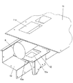
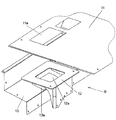
図2、3に示すように、本実施形態は、エンジンルーム5内に設けられたエンジン17と、車体カバー11の下方にブラケット12を介して設けられ、エンジン17の排気音を消音する前述のマフラ8と、このマフラ8と油圧ポンプ16とを仕切る仕切カバー13とを備えており、マフラ8の周囲が車体カバー11、ブラケット12、及び仕切カバー13によって覆われている。なお、マフラ8は、エンジン17の排気ガスを処理する排ガス後処理装置と一体型となっている。
As shown in FIGS. 2 and 3, this embodiment is provided with the
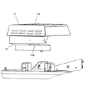
図4〜7に示すように、本実施形態は、車体カバー11のマフラ8の上方に位置する部分にマフラ8及びマフラ8の周辺の清掃を可能とする清掃用の第1の開口11aを有している。そして、ブラケット12はマフラ8の下方に位置する部分に清掃用の第2の開口12aを有している。さらに、仕切カバー13は清掃用の第3の開口13aを有している。また、本実施形態は、第1の開口11a及び第3の開口13aのうち少なくとも一方、例えば図3に示すように第1の開口11a及び第3の開口13aの双方がそれぞれ後述のヒンジ11b,13bによって開閉する開閉扉11A,13Aから成っている。すなわち、本実施形態は、図3に示すように第1の開口11aの近傍に配置され、車体カバー11の上部に取り付けられたヒンジ11bと、第3の開口13aの近傍に配置され、仕切カバー13の下部に取り付けられたヒンジ13bとを有している。そして、開閉扉11Aはヒンジ11bによって上方へ開くようになっており、開閉扉13Aはヒンジ13bによって下方へ開くようになっている。また、本実施形態は、図3に示すように開閉扉11A、第1の開口11a、マフラ8、第2の開口12a、第3の開口13a、及び開閉扉13Aがそれぞれ同一直線L−L上に配置されている。なお、第1の開口11a及び第3の開口13aに設けられる開閉扉11A,13Aは、ヒンジ11b,13bの代わりにボルト等によって着脱するようにしても良い。
As shown in FIGS. 4 to 7, this embodiment has a
このように構成した本実施形態によれば、前述したようにマフラ8の周囲が図2〜5に示すように車体カバー11、ブラケット12、及び仕切カバー13によって覆われていても、作業者がマフラ8及びマフラ8の周辺を清掃するときには、作業者はエンジンルーム5の外側から車体カバー11に設けられた第1の開口11aを通してマフラ8及びマフラ8の周辺を容易に清掃することができる。例えば、作業者が、開閉扉11A,13Aを開き、車体カバー11の上から第1の開口11aを介してマフラ8にエアーを吹き掛けることにより、マフラ8、及びマフラ8の周辺のブラケット12や仕切カバー13に付着した塵埃を第2の開口12a及び第3の開口13aに落としてマフラ8及びマフラ8の周辺から取り除くことができる。また、作業者は第1の開口11aから手作業によってマフラ8及びマフラ8の周辺に付着した塵埃を取り除くこともできる。従って、マフラ8とブラケット12との間の隙間のようにマフラ8の周辺のうち塵埃が溜まり易い場所であっても、作業者が第1の開口11aからマフラ8及びマフラ8の周辺を定期的に清掃することにより、塵埃がマフラ8及びマフラ8の周辺に堆積することを防止することができる。このように、堆積した塵埃がマフラ8及びマフラ8の周辺に付着することを防ぐことができ、高い安全性を確保することができる。
According to this embodiment configured as above, even if the periphery of the
また、本実施形態は、ブラケット12はマフラ8の下方に位置する部分に清掃用の第2の開口12aを有しており、この第2の開口12aからブラケット12に堆積する塵埃を逃がすことができるので、塵埃の溜まり易いマフラ8とブラケット12との間の隙間に塵埃が堆積することを抑えることができる。
Further, in the present embodiment, the
また、本実施形態は、仕切カバー13は清掃用の第3の開口13aを有しており、仕切カバー13によって油圧ポンプ16から飛散した油がマフラ8方向へ飛散することを防止することができ、さらに仕切カバー13の第3の開口13aからブラケット12に堆積する塵埃を逃がすことができるので、マフラ8の周辺に塵埃が堆積することを抑えることができる。
In this embodiment, the
また、本実施形態は、図3に示すように第1の開口11a及び第3の開口13aの双方がそれぞれヒンジ11b,13bによって開閉する開閉扉11A,13Aから成っているので、作業者がマフラ8及びマフラ8の周辺の清掃作業を行うときには、開閉扉11A,13Aをそれぞれ開くことにより、第1の開口11a及び第3の開口13aの双方を容易に開放することができる。これにより、マフラ8及びマフラ8の周辺の清掃作業における作業者の負担を軽減することができる。さらに、作業者がマフラ8及びマフラ8の周辺の清掃作業を終えるときには、開閉扉11A,13Aをそれぞれ閉めることにより、第1の開口11a及び第3の開口13aの双方に容易に蓋をすることができ、利便性が良い。
Further, in the present embodiment, as shown in FIG. 3, both the
また、本実施形態は、図3に示すように開閉扉11A、第1の開口11a、マフラ8、第2の開口12a、第3の開口13a、及び開閉扉13Aがそれぞれ同一直線L−L上に配置されているので、例えば作業者が車体カバー11の上から第1の開口11aを通してエアーを吹き掛けることにより、マフラ8及びマフラ8の周辺に付着した塵埃を第2の開口12a及び第3の開口13aへ落とし易くなっている。従って、マフラ8及びマフラ8の周辺の清掃作業の高い能率を確保することができる。また、ブラケット12上に付着した塵埃が第2の開口12aから落ちると、そのまま第3の開口13aへ落ちるので、塵埃の溜まり易いマフラ8とブラケット12との間の隙間に塵埃が堆積することをより抑えることができる。
In the present embodiment, as shown in FIG. 3, the opening /
1 油圧ショベル(建設機械)
2 走行体
3 旋回体
3a 旋回フレーム
4 フロント作業機
5 エンジンルーム
6 カウンタウェイト
7 キャブ
8 マフラ
10 排気口
11 車体カバー
11A 開閉扉
11a 第1の開口
11b ヒンジ
12 ブラケット
12a 第2の開口
13 仕切カバー
13A 開閉扉
13a 第3の開口
13b ヒンジ
16 油圧ポンプ
17 エンジン
1 Excavator (construction machine)
2 traveling body 3 revolving
Claims (3)
前記車体カバーの前記マフラの上方に位置する部分に前記マフラ及び前記マフラの周辺の清掃を可能とする清掃用の第1の開口を備え、
前記仕切カバーは清掃用の第3の開口を有することを特徴とする建設機械。 In a construction machine comprising a vehicle body cover that covers the engine, a muffler that is provided below the vehicle body cover via a bracket and that silences the exhaust sound of the engine, and a partition cover that partitions the muffler and the hydraulic pump.
A first opening for cleaning that enables cleaning of the muffler and the periphery of the muffler in a portion of the vehicle body cover located above the muffler ;
The construction machine characterized in that the partition cover has a third opening for cleaning .
前記ブラケットは前記マフラの下方に位置する部分に清掃用の第2の開口を有することを特徴とする建設機械。 The construction machine according to claim 1,
2. The construction machine according to claim 1, wherein the bracket has a second opening for cleaning at a portion located below the muffler.
前記第1の開口及び前記第3の開口のうち少なくとも一方は開閉式の開閉窓から成ることを特徴とする建設機械。 In the construction machine according to claim 1 or 2,
Wherein at least one of the first opening and the third opening construction machine characterized by forming Rukoto from open opening windows.
Priority Applications (1)
| Application Number | Priority Date | Filing Date | Title |
|---|---|---|---|
| JP2010113393A JP5386434B2 (en) | 2010-05-17 | 2010-05-17 | Construction machinery |
Applications Claiming Priority (1)
| Application Number | Priority Date | Filing Date | Title |
|---|---|---|---|
| JP2010113393A JP5386434B2 (en) | 2010-05-17 | 2010-05-17 | Construction machinery |
Publications (2)
| Publication Number | Publication Date |
|---|---|
| JP2011241570A JP2011241570A (en) | 2011-12-01 |
| JP5386434B2 true JP5386434B2 (en) | 2014-01-15 |
Family
ID=45408512
Family Applications (1)
| Application Number | Title | Priority Date | Filing Date |
|---|---|---|---|
| JP2010113393A Active JP5386434B2 (en) | 2010-05-17 | 2010-05-17 | Construction machinery |
Country Status (1)
| Country | Link |
|---|---|
| JP (1) | JP5386434B2 (en) |
Cited By (1)
| Publication number | Priority date | Publication date | Assignee | Title |
|---|---|---|---|---|
| US9657459B2 (en) | 2014-11-17 | 2017-05-23 | Kobelco Construction Machinery Co., Ltd. | Construction machine |
Families Citing this family (4)
| Publication number | Priority date | Publication date | Assignee | Title |
|---|---|---|---|---|
| JP5670943B2 (en) * | 2012-03-27 | 2015-02-18 | 日立建機株式会社 | Work machine |
| WO2014091950A1 (en) * | 2012-12-11 | 2014-06-19 | 日立建機株式会社 | Hydraulic-oil spatter prevention device for construction machine |
| JP6417163B2 (en) * | 2014-09-16 | 2018-10-31 | 日立建機株式会社 | Work machine |
| JP7034798B2 (en) * | 2018-03-29 | 2022-03-14 | 住友建機株式会社 | Excavator |
Family Cites Families (5)
| Publication number | Priority date | Publication date | Assignee | Title |
|---|---|---|---|---|
| JP2000289656A (en) * | 1999-04-12 | 2000-10-17 | Hitachi Constr Mach Co Ltd | Small inspecting window for engine cover |
| JP2001303614A (en) * | 2000-04-20 | 2001-10-31 | Komatsu Ltd | Shielding plate for hydraulic backhoe |
| JP2004340114A (en) * | 2003-05-19 | 2004-12-02 | Hitachi Constr Mach Co Ltd | Muffler support device |
| JP2005068810A (en) * | 2003-08-25 | 2005-03-17 | Hitachi Constr Mach Co Ltd | Shielding device for construction machine |
| JP2010215122A (en) * | 2009-03-17 | 2010-09-30 | Hitachi Constr Mach Co Ltd | Engine cover for construction machine |
-
2010
- 2010-05-17 JP JP2010113393A patent/JP5386434B2/en active Active
Cited By (1)
| Publication number | Priority date | Publication date | Assignee | Title |
|---|---|---|---|---|
| US9657459B2 (en) | 2014-11-17 | 2017-05-23 | Kobelco Construction Machinery Co., Ltd. | Construction machine |
Also Published As
| Publication number | Publication date |
|---|---|
| JP2011241570A (en) | 2011-12-01 |
Similar Documents
| Publication | Publication Date | Title |
|---|---|---|
| JP5386434B2 (en) | Construction machinery | |
| WO2009104592A1 (en) | Construction machine | |
| JP2008008257A (en) | Exhaust structure of construction machine | |
| JP5356349B2 (en) | Exhaust equipment for construction machinery | |
| JP5507769B1 (en) | Wheel loader | |
| JP2014144678A (en) | Work machine | |
| JP6115960B2 (en) | Hood equipment and work machine | |
| JP5381165B2 (en) | Construction machinery | |
| JP7444418B2 (en) | construction machinery | |
| JP6417163B2 (en) | Work machine | |
| JP6877225B2 (en) | combine | |
| JP6811116B2 (en) | Construction machinery | |
| JP6047479B2 (en) | Exhaust equipment for construction machinery | |
| JP5729244B2 (en) | Construction machinery | |
| JP5415228B2 (en) | Construction machinery | |
| JP2015183589A (en) | work machine | |
| JP5567240B1 (en) | Work vehicle | |
| JP2015098727A (en) | Construction machinery | |
| JP2013083214A (en) | Exhaust device for construction machine | |
| JP2013104276A (en) | Filter device for construction machine | |
| JP6171561B2 (en) | Work machine | |
| JP2005325590A (en) | Engine room of construction machine | |
| JP2021169271A (en) | Construction machine | |
| JP2576575B2 (en) | Engine hood device for industrial vehicles | |
| JP5566444B2 (en) | Cab for construction machinery |
Legal Events
| Date | Code | Title | Description |
|---|---|---|---|
| A621 | Written request for application examination |
Free format text: JAPANESE INTERMEDIATE CODE: A621 Effective date: 20120528 |
|
| A977 | Report on retrieval |
Free format text: JAPANESE INTERMEDIATE CODE: A971007 Effective date: 20130516 |
|
| A131 | Notification of reasons for refusal |
Free format text: JAPANESE INTERMEDIATE CODE: A131 Effective date: 20130528 |
|
| A521 | Written amendment |
Free format text: JAPANESE INTERMEDIATE CODE: A523 Effective date: 20130724 |
|
| TRDD | Decision of grant or rejection written | ||
| A01 | Written decision to grant a patent or to grant a registration (utility model) |
Free format text: JAPANESE INTERMEDIATE CODE: A01 Effective date: 20131001 |
|
| A61 | First payment of annual fees (during grant procedure) |
Free format text: JAPANESE INTERMEDIATE CODE: A61 Effective date: 20131007 |
|
| R150 | Certificate of patent or registration of utility model |
Ref document number: 5386434 Country of ref document: JP Free format text: JAPANESE INTERMEDIATE CODE: R150 Free format text: JAPANESE INTERMEDIATE CODE: R150 |