JP5385607B2 - Gated current measuring instrument - Google Patents
Gated current measuring instrument Download PDFInfo
- Publication number
- JP5385607B2 JP5385607B2 JP2008522921A JP2008522921A JP5385607B2 JP 5385607 B2 JP5385607 B2 JP 5385607B2 JP 2008522921 A JP2008522921 A JP 2008522921A JP 2008522921 A JP2008522921 A JP 2008522921A JP 5385607 B2 JP5385607 B2 JP 5385607B2
- Authority
- JP
- Japan
- Prior art keywords
- sample
- current
- analyte
- seconds
- pulse
- Prior art date
- Legal status (The legal status is an assumption and is not a legal conclusion. Google has not performed a legal analysis and makes no representation as to the accuracy of the status listed.)
- Active
Links
Images


Classifications
-
- G—PHYSICS
- G01—MEASURING; TESTING
- G01N—INVESTIGATING OR ANALYSING MATERIALS BY DETERMINING THEIR CHEMICAL OR PHYSICAL PROPERTIES
- G01N27/00—Investigating or analysing materials by the use of electric, electrochemical, or magnetic means
- G01N27/26—Investigating or analysing materials by the use of electric, electrochemical, or magnetic means by investigating electrochemical variables; by using electrolysis or electrophoresis
- G01N27/416—Systems
- G01N27/49—Systems involving the determination of the current at a single specific value, or small range of values, of applied voltage for producing selective measurement of one or more particular ionic species
-
- G—PHYSICS
- G01—MEASURING; TESTING
- G01N—INVESTIGATING OR ANALYSING MATERIALS BY DETERMINING THEIR CHEMICAL OR PHYSICAL PROPERTIES
- G01N27/00—Investigating or analysing materials by the use of electric, electrochemical, or magnetic means
- G01N27/26—Investigating or analysing materials by the use of electric, electrochemical, or magnetic means by investigating electrochemical variables; by using electrolysis or electrophoresis
-
- A—HUMAN NECESSITIES
- A61—MEDICAL OR VETERINARY SCIENCE; HYGIENE
- A61B—DIAGNOSIS; SURGERY; IDENTIFICATION
- A61B5/00—Measuring for diagnostic purposes; Identification of persons
-
- A—HUMAN NECESSITIES
- A61—MEDICAL OR VETERINARY SCIENCE; HYGIENE
- A61B—DIAGNOSIS; SURGERY; IDENTIFICATION
- A61B5/00—Measuring for diagnostic purposes; Identification of persons
- A61B5/145—Measuring characteristics of blood in vivo, e.g. gas concentration, pH value; Measuring characteristics of body fluids or tissues, e.g. interstitial fluid, cerebral tissue
- A61B5/14532—Measuring characteristics of blood in vivo, e.g. gas concentration, pH value; Measuring characteristics of body fluids or tissues, e.g. interstitial fluid, cerebral tissue for measuring glucose, e.g. by tissue impedance measurement
-
- A—HUMAN NECESSITIES
- A61—MEDICAL OR VETERINARY SCIENCE; HYGIENE
- A61B—DIAGNOSIS; SURGERY; IDENTIFICATION
- A61B5/00—Measuring for diagnostic purposes; Identification of persons
- A61B5/145—Measuring characteristics of blood in vivo, e.g. gas concentration, pH value; Measuring characteristics of body fluids or tissues, e.g. interstitial fluid, cerebral tissue
- A61B5/14546—Measuring characteristics of blood in vivo, e.g. gas concentration, pH value; Measuring characteristics of body fluids or tissues, e.g. interstitial fluid, cerebral tissue for measuring analytes not otherwise provided for, e.g. ions, cytochromes
-
- A—HUMAN NECESSITIES
- A61—MEDICAL OR VETERINARY SCIENCE; HYGIENE
- A61B—DIAGNOSIS; SURGERY; IDENTIFICATION
- A61B5/00—Measuring for diagnostic purposes; Identification of persons
- A61B5/145—Measuring characteristics of blood in vivo, e.g. gas concentration, pH value; Measuring characteristics of body fluids or tissues, e.g. interstitial fluid, cerebral tissue
- A61B5/1486—Measuring characteristics of blood in vivo, e.g. gas concentration, pH value; Measuring characteristics of body fluids or tissues, e.g. interstitial fluid, cerebral tissue using enzyme electrodes, e.g. with immobilised oxidase
-
- C—CHEMISTRY; METALLURGY
- C12—BIOCHEMISTRY; BEER; SPIRITS; WINE; VINEGAR; MICROBIOLOGY; ENZYMOLOGY; MUTATION OR GENETIC ENGINEERING
- C12Q—MEASURING OR TESTING PROCESSES INVOLVING ENZYMES, NUCLEIC ACIDS OR MICROORGANISMS; COMPOSITIONS OR TEST PAPERS THEREFOR; PROCESSES OF PREPARING SUCH COMPOSITIONS; CONDITION-RESPONSIVE CONTROL IN MICROBIOLOGICAL OR ENZYMOLOGICAL PROCESSES
- C12Q1/00—Measuring or testing processes involving enzymes, nucleic acids or microorganisms; Compositions therefor; Processes of preparing such compositions
- C12Q1/001—Enzyme electrodes
- C12Q1/005—Enzyme electrodes involving specific analytes or enzymes
- C12Q1/006—Enzyme electrodes involving specific analytes or enzymes for glucose
-
- C—CHEMISTRY; METALLURGY
- C12—BIOCHEMISTRY; BEER; SPIRITS; WINE; VINEGAR; MICROBIOLOGY; ENZYMOLOGY; MUTATION OR GENETIC ENGINEERING
- C12Q—MEASURING OR TESTING PROCESSES INVOLVING ENZYMES, NUCLEIC ACIDS OR MICROORGANISMS; COMPOSITIONS OR TEST PAPERS THEREFOR; PROCESSES OF PREPARING SUCH COMPOSITIONS; CONDITION-RESPONSIVE CONTROL IN MICROBIOLOGICAL OR ENZYMOLOGICAL PROCESSES
- C12Q1/00—Measuring or testing processes involving enzymes, nucleic acids or microorganisms; Compositions therefor; Processes of preparing such compositions
- C12Q1/26—Measuring or testing processes involving enzymes, nucleic acids or microorganisms; Compositions therefor; Processes of preparing such compositions involving oxidoreductase
-
- G—PHYSICS
- G01—MEASURING; TESTING
- G01N—INVESTIGATING OR ANALYSING MATERIALS BY DETERMINING THEIR CHEMICAL OR PHYSICAL PROPERTIES
- G01N27/00—Investigating or analysing materials by the use of electric, electrochemical, or magnetic means
- G01N27/26—Investigating or analysing materials by the use of electric, electrochemical, or magnetic means by investigating electrochemical variables; by using electrolysis or electrophoresis
- G01N27/28—Electrolytic cell components
- G01N27/30—Electrodes, e.g. test electrodes; Half-cells
- G01N27/327—Biochemical electrodes, e.g. electrical or mechanical details for in vitro measurements
- G01N27/3271—Amperometric enzyme electrodes for analytes in body fluids, e.g. glucose in blood
- G01N27/3273—Devices therefor, e.g. test element readers, circuitry
-
- G—PHYSICS
- G01—MEASURING; TESTING
- G01N—INVESTIGATING OR ANALYSING MATERIALS BY DETERMINING THEIR CHEMICAL OR PHYSICAL PROPERTIES
- G01N33/00—Investigating or analysing materials by specific methods not covered by groups G01N1/00 - G01N31/00
- G01N33/48—Biological material, e.g. blood, urine; Haemocytometers
- G01N33/483—Physical analysis of biological material
- G01N33/487—Physical analysis of biological material of liquid biological material
-
- A—HUMAN NECESSITIES
- A61—MEDICAL OR VETERINARY SCIENCE; HYGIENE
- A61B—DIAGNOSIS; SURGERY; IDENTIFICATION
- A61B2562/00—Details of sensors; Constructional details of sensor housings or probes; Accessories for sensors
- A61B2562/02—Details of sensors specially adapted for in-vivo measurements
- A61B2562/0295—Strip shaped analyte sensors for apparatus classified in A61B5/145 or A61B5/157
Description
関連する出願の参照
[001] 本出願は、「ゲート化電流測定器」と題した2005年7月20日付出願の米国仮出願番号60/700,787、および「バイオセンサ用の異常出力検出システム」と題した2006年5月8日付出願の米国仮出願番号60/746,771の利益を主張し、それらの全ての内容は本明細書中に参考文献として援用されている。
Reference to related applications
[001] This application is a US
本発明の背景
[002] 生物学的液体中の分析目的物の定量測定は、生理学的異常の診断および治療に有用である。例えば、血液などの生物学的液体中のグルコース濃度を決定することは、頻繁に血糖値をして、食事内容および/または薬物療法を制御しなければならない糖尿病患者個体にとって重要である。
Background of the invention
[002] Quantitative determination of analytes in biological fluids is useful for diagnosis and treatment of physiological abnormalities. For example, determining the concentration of glucose in biological fluids such as blood is important for diabetic individuals who have frequent blood glucose levels and must control dietary content and / or medication.
[003] このタイプの分析には、電気化学的システムが用いられてきている。分析の過程において、分析目的物は、酵素または同様の種との酸化還元反応を受けて電流を生じ、この電流を測定できるとともに目的分析物の濃度に相関させることができる。望まれる正確性および精度によって提供される一方、分析に必要な時間を減少させることにより、使用者にとっての実質的な利点を提供することができる。 [003] Electrochemical systems have been used for this type of analysis. During the course of the analysis, the analyte of interest undergoes a redox reaction with an enzyme or similar species to produce an electric current that can be measured and correlated to the concentration of the analyte of interest. While provided by the accuracy and precision desired, reducing the time required for analysis can provide substantial benefits to the user.
[004] 生物学的液体中の分析目的物を分析するための電気化学的センサシステムの一例には、測定装置およびセンサストリップが含まれる。センサストリップには、分析の過程で分析目的物と反応するとともに分析目的物から電子を移動する試薬、およびストリップを装置に接続する伝導体を通して電子を通す電極が含まれる。測定装置には、ストリップから電子を受け取る接点、および接点間で異なる電圧を印加する能力が含まれる。装置はセンサを通った電流を記録し、また電流値をサンプルの分析目的物含量の測定に変換することができる。これらのセンサシステムは1〜15マイクロリットル(μl)量などの、一滴の全血(WB)を分析することができる。 [004] An example of an electrochemical sensor system for analyzing an analyte in a biological fluid includes a measuring device and a sensor strip. The sensor strip includes a reagent that reacts with the analyte of interest during the course of analysis and transfers electrons from the analyte of interest, and an electrode that conducts electrons through a conductor that connects the strip to the device. The measuring device includes contacts that receive electrons from the strip and the ability to apply different voltages between the contacts. The device records the current through the sensor and can convert the current value into a measurement of the analyte content of the sample. These sensor systems can analyze a drop of whole blood (WB), such as a 1-15 microliter (μl) volume.
[005] 卓上測定装置の例として、BAS Instruments社(米国インディアナ州West Lafayette)から販売されているBAS 100B Analyzer、CH Instruments社(米国テキサス州Austin)から販売されているCH Instrument Analyzer、Cypress Systems社(米国カンザス州Lawrence)から販売されているCypress Electrochemical Workstation、およびPrinceton Research Instruments社(米国ニュージャージー州Princeton)から販売されているEG&G Electrochemical Instrumentが含まれる。携帯型測定装置の例には、Bayer社のAscensia Breeze(登録商標)およびAscensia Elite(登録商標)メーターが含まれる。 [005] Examples of tabletop measuring devices include BAS 100B Analyzer sold by BAS Instruments (West Lafayette, Indiana, USA), CH Instrument Analyzer sold by CH Instruments (Austin, Texas, USA), and Cypress Systems. (Cypress Electrochemical Workstation sold by Lawrence, Kansas, USA) and EG & G Electrochemical Instrument sold by Princeton Research Instruments (Princeton, NJ, USA). Examples of portable measuring devices include Bayer's Ascensia Breeze (R) and Ascensia Elite (R) meters.
[006] センサストリップには、分析目的物が電気化学的な反応をする作用電極および逆の電気化学的反応をする対電極が含まれていてもよいため、電極間に電流を流すことが可能である。したがって、もし酸化が作用電極で起きる場合、還元が対電極で起こる。例えば、Fundamentals Of Analytical Chemistry第4版(D.A. Skoog and D.M. West; Philadelphia: Saunders College Publishing (1982), pp 304-341)を参照されたい。 [006] The sensor strip may include a working electrode where the analyte is electrochemically reacted and a counter electrode that is oppositely electrochemical, allowing current to flow between the electrodes. It is. Thus, if oxidation occurs at the working electrode, reduction occurs at the counter electrode. See, for example, Fundamentals Of Analytical Chemistry 4th Edition (D.A. Skoog and D.M. West; Philadelphia: Saunders College Publishing (1982), pp 304-341).
[007] センサストリップにはまた、測定装置に対して固定(non-variant)参照電位を提供する正確な参照電極が含まれていてもよい。複数の参照電極材が知られているが、分析溶液の水性環境中での混合物の不溶性のため、不溶の銀(Ag)および塩化銀(AgCl)の混合物が一般的である。参照電極はまた、対電極として用いられてもよい。このような参照電極−対電極の組み合わせを使用するセンサストリップは、米国特許番号5,820,551号に記載されている。 [007] The sensor strip may also include an accurate reference electrode that provides a non-variant reference potential to the measurement device. Several reference electrode materials are known, but mixtures of insoluble silver (Ag) and silver chloride (AgCl) are common because of the insolubility of the mixture in the aqueous environment of the analytical solution. The reference electrode may also be used as a counter electrode. A sensor strip using such a reference electrode-counter electrode combination is described in US Pat. No. 5,820,551.
[008] センサストリップは、米国特許番号6,531,040号、5,798,031号および5,120,420号に記載されているような、複数の技術を用いて絶縁物質上に電極を印刷することによって形成されてもよい。一層または複数層の試薬層は、作用電極および/または対電極などの、一種類または複数種類の電極をコーティングすることによって形成されてもよい。一つの態様では、作用電極および対電極が同じ組成物でコーティングされる場合のように、一種類以上の電極が同じ試薬層によって覆われてもよい。別の態様では、2003年10月24日付出願の米国仮出願番号60/513,817に記載された方法を用いて、異なる組成物を有する試薬層は、作用電極および対電極上に印刷するか、またはマイクロ固着させてもよい。したがって、作用電極上の試薬層は酵素、メディエータ、および結合剤を含んでもよく、対電極上の試薬層はメディエータと同じまたはメディエータと異なっていてもよい可溶性酸化還元種、および結合剤を含んでもよい。 [008] Sensor strips may be formed by printing electrodes on an insulating material using a plurality of techniques, such as those described in US Pat. Nos. 6,531,040, 5,798,031 and 5,120,420. One or more reagent layers may be formed by coating one or more types of electrodes, such as a working electrode and / or a counter electrode. In one embodiment, one or more electrodes may be covered by the same reagent layer, such as when the working and counter electrodes are coated with the same composition. In another embodiment, using the method described in US Provisional Application No. 60 / 513,817, filed October 24, 2003, reagent layers having different compositions are printed on the working electrode and the counter electrode, or You may make it micro adhere. Thus, the reagent layer on the working electrode may contain enzymes, mediators, and binders, and the reagent layer on the counter electrode may contain soluble redox species that may be the same as or different from the mediators, and binders. Good.
[009] 試薬層には、分析目的物と伝導体の間で電子移動を補助するメディエータまたは他の物質、並びに分析目的物の酸化または還元を促進するためのイオン化薬剤(ionizing agent)が含まれていてもよい。イオン化薬剤は、グルコースオキシダーゼまたはグルコースデヒドロゲナーゼなどの、全血サンプル中のグルコース酸化を触媒する、分析目的物に特異的な酵素であってもよい。試薬層にはまた、酵素とメディエータを同時に保持する結合剤が含まれていてもよい。以下の表Iは、特異的分析目的物とともに使用される酵素およびメディエータの通常の組み合わせを示す。 [009] The reagent layer includes a mediator or other substance that assists in the electron transfer between the analyte and the conductor, and an ionizing agent to promote oxidation or reduction of the analyte. It may be. The ionizing agent may be an analyte-specific enzyme that catalyzes glucose oxidation in a whole blood sample, such as glucose oxidase or glucose dehydrogenase. The reagent layer may also contain a binder that simultaneously holds the enzyme and the mediator. Table I below shows common combinations of enzymes and mediators used with specific analytes.

[0010] 結合剤には、CMC(カルボキシルメチルセルロース)および/またはPEO(ポリエチレンオキシド)などの、さまざまなタイプおよび分子量の重合体が含まれてもよい。試薬同士を結合することに加えて、結合剤は、赤血球のふるい分けを補助することで、赤血球が電極表面に付着することを防ぐ働きをしてもよい。 [0010] The binder may include polymers of various types and molecular weights, such as CMC (carboxyl methylcellulose) and / or PEO (polyethylene oxide). In addition to binding reagents together, the binding agent may serve to prevent red blood cells from adhering to the electrode surface by assisting in the screening of red blood cells.
[0011] 生物学的液体中の分析目的物を分析するための従来の電気化学的センサシステムの例には、Abbott社(米国イリノイ州Abbott Park)から販売されているPrecision(登録商標)バイオセンサ、Roche社(米国インディアナ州Indianapolis)から販売されているAccucheck(登録商標)バイオセンサ、Lifescan社(米国カリフォルニア州Milpitas)から販売されているOneTouch Ultra(登録商標)バイオセンサが含まれる。 [0011] Examples of conventional electrochemical sensor systems for analyzing analytes in biological fluids include Precision® biosensors sold by Abbott (Abbott Park, Illinois, USA) And AccuCheck® biosensor sold by Roche (Indianapolis, Indiana, USA) and OneTouch Ultra® biosensor sold by Lifescan (Milpitas, CA, USA).
[0012] 生物学的液体中の分析目的物を定量するのに用いられている一つの電気化学的方法は電量測定法である。例えば、Hellerらは全血グルコース測定の電量的方法(coulometric method)を、米国特許番号6,120,676号に記載している。電量測定法では、分析目的物の濃度は少容量中で分析目的物を完全に酸化すること、および酸化している時間に対する電流を積分することにより分析目的物の濃度を示す電荷を生成すること、によって定量される。換言すれば、電量測定法はセンサストリップ内のグルコース総量を捕捉するということである。 [0012] One electrochemical method that has been used to quantify analytes in biological fluids is coulometry. For example, Heller et al. Describe a coulometric method for measuring whole blood glucose in US Pat. No. 6,120,676. In the coulometric method, the concentration of the analyte is completely oxidized in a small volume, and a charge indicating the concentration of the analyte is generated by integrating the current against the oxidation time. Quantified by In other words, the coulometric method captures the total amount of glucose in the sensor strip.
[0013] 電量測定法の重要な側面は、電荷対時間の積分曲線の終点に向けて、電流が時間とともに変化する割合が実質的に一定になることで、定常状態条件をもたらすことである。電量的曲線の定常状態の部分は、比較的平らなプラトー領域を形成するため、相当する電流値の決定が可能となる。しかしながら、電量的方法は分析目的物の全体量が完全に転換し、定常状態条件に達することを必要とする。結果的に、この方法は時間がかかるものであること、またグルコースモニタリング製品などの電気化学的装置の使用者が必要とする迅速な結果を供給できない。電量測定法の別の問題は、正確な結果を出すには少容量のセンサセルが調整されなければならず、そのことは量産装置では困難なことである。 [0013] An important aspect of the coulometric method is that the rate at which the current changes with time becomes substantially constant toward the end of the integral curve of charge versus time, resulting in a steady state condition. The steady state portion of the coulometric curve forms a relatively flat plateau region, so that the corresponding current value can be determined. However, the coulometric method requires that the total amount of the analyte of interest be completely converted and reach steady state conditions. As a result, this method is time consuming and fails to provide the rapid results required by users of electrochemical devices such as glucose monitoring products. Another problem with coulometry is that small-capacity sensor cells must be adjusted for accurate results, which is difficult with mass production equipment.
[0014] 生物学的液体中の分析目的物を定量するのに用いられている他の電気化学的方法は、電流測定法である。電流測定法では、電流は、センサストリップの作用電極および対電極間に印加される定電位(電圧)としての読み取りパルス中に測定される。測定された電流を用いて、サンプル中の分析目的物を定量する。電流測定は電気化学的活性種、すなわち目的分析物が作用電極付近で酸化または還元される速度を計測する。バイオセンサのための電流測定方法の多数のバリエーションは、例えば米国特許番号5,620,579号、5,653,863号、6,153,069号および6,413,411号に記載されている。 [0014] Another electrochemical method that has been used to quantify analytes in biological fluids is amperometry. In amperometry, the current is measured during a read pulse as a constant potential (voltage) applied between the working and counter electrodes of the sensor strip. Using the measured current, the analyte in the sample is quantified. Current measurement measures the rate at which the electrochemically active species, ie the analyte of interest, is oxidized or reduced near the working electrode. Numerous variations of current measurement methods for biosensors are described, for example, in US Pat. Nos. 5,620,579, 5,653,863, 6,153,069, and 6,413,411.
[0015] 従来の電流測定法での欠点は、電位が印加された後の、電流の非定常状態の性質である。時間に対する電流変化率は、初期に非常に急速であり、そして拡散過程の変化する性質によって、分析が進行するにつれて、遅くなる。電極表面での還元メディエータの消費速度が拡散速度と等しくなるまでは、定常状態の電流値は得られない。したがって、電流測定法では、定常状態の条件に達する前の一過性の期間に電流を測定することが、定常状態の時間に行われる測定よりも、不正確になる可能性がある。 [0015] A drawback with conventional current measurement methods is the unsteady state nature of the current after the potential is applied. The rate of current change over time is very rapid initially and slows as the analysis proceeds due to the changing nature of the diffusion process. A steady-state current value cannot be obtained until the consumption rate of the reducing mediator on the electrode surface becomes equal to the diffusion rate. Thus, in current measurement methods, measuring current during a transient period before reaching steady state conditions may be less accurate than measurements performed during steady state time.
[0016] 「ヘマトクリット効果」は全血サンプル中のグルコース濃度を正確に分析することを妨害する。全血サンプルは赤血球(RB細胞)および血漿を含む。血漿は主に水分であるが、いくらかのタンパク質およびグルコースを含む。ヘマトクリットは、全血サンプルの総容積に対する赤血球成分の容積であり、また、しばしばパーセンテージで表される。全血サンプルは一般的にヘマトクリット値の範囲が20%から60%であり、約40%が平均値である。 [0016] The "hematocrit effect" hinders accurate analysis of glucose concentration in whole blood samples. Whole blood samples include red blood cells (RB cells) and plasma. Plasma is primarily water but contains some protein and glucose. The hematocrit is the volume of the red blood cell component relative to the total volume of the whole blood sample and is often expressed as a percentage. Whole blood samples generally have a hematocrit range of 20% to 60%, with an average value of about 40%.
[0017] グルコース濃度を決定するための従来のセンサストリップでは、グルコースは酵素によって酸化されることができ、その後電子がメディエータに移動される。還元メディエータはその後、作用電極へと移動し、そこで電気化学的に酸化される。酸化されたメディエータ量は、センサストリップの作用電極および対電極間を流れる電流に相関していると考えられる。定量的には、作用電極で測定された電流は、メディエータの拡散係数に直接的に比例する。ヘマトクリット効果はこのプロセスを妨害し、その理由として赤血球が作用電極へのメディエータの拡散を妨害するためである。その後、ヘマトクリット効果はサンプル中のグルコース量と何ら関係することなしに、作用電極で測定された電流量に影響する。 [0017] In conventional sensor strips for determining glucose concentration, glucose can be oxidized by an enzyme, and then electrons are transferred to a mediator. The reducing mediator then moves to the working electrode where it is electrochemically oxidized. The amount of mediator oxidized is believed to correlate with the current flowing between the working and counter electrodes of the sensor strip. Quantitatively, the current measured at the working electrode is directly proportional to the mediator diffusion coefficient. The hematocrit effect interferes with this process because red blood cells interfere with the mediator diffusion to the working electrode. The hematocrit effect then affects the amount of current measured at the working electrode without any relation to the amount of glucose in the sample.
[0018] 様々な濃度の赤血球を有する全血サンプルは、測定において不正確性を引き起こす可能性がある。その理由として、赤血球が作用電極への拡散を防ぐため、センサは低濃度のメディエータと高濃度のメディエータを区別できない可能性があるためである。例えば、同濃度のグルコースを含んでいるが、20、40および60%のヘマトクリットを有する全血サンプルが分析された場合、1組の較正定数(例えば検量線の傾きおよび切片)に基づく従来のセンサシステムでは、3つの異なるグルコース測定値が記録されるであろう。グルコース濃度が同一であっても、このシステムでは20%のヘマトクリットサンプルが、60%のヘマトクリットサンプルよりも多いグルコースを含むと記録されると考えられ、これは赤血球が作用電極へのメディエータの拡散を妨害するためである。 [0018] Whole blood samples having various concentrations of red blood cells can cause inaccuracies in the measurement. The reason is that the red blood cells are prevented from diffusing into the working electrode, so the sensor may not be able to distinguish between low and high mediators. For example, if a whole blood sample containing the same concentration of glucose but with 20, 40 and 60% hematocrit was analyzed, a conventional sensor based on a set of calibration constants (eg, calibration curve slope and intercept) In the system, three different glucose measurements will be recorded. Even with the same glucose concentration, the system would record 20% hematocrit samples to contain more glucose than 60% hematocrit samples, which would cause red blood cells to diffuse the mediator to the working electrode. This is to obstruct.
[0019] ヒトの正常なヘマトクリット値の範囲(赤血球濃度)は、20%から60%であり、およそ40%が中間値である。ヘマトクリットバイアスは、YSI社(米国オハイオ州Yellow Springs)から発売されているYSI 2300 STAT PLUS(登録商標)などの、基準機器によって得られた基準グルコース濃度と、異なるヘマトクリットレベルを含むサンプルのための携帯型センサシステムから得られた実験的グルコース測定値との間の差について表す。基準値と実験値との差は、特定の全血サンプル間での異なるヘマトクリット値から生じる。 [0019] The normal range of human hematocrit (red blood cell concentration) is 20% to 60%, with approximately 40% being an intermediate value. Hematocrit bias is a portable instrument for samples containing different reference hematocrit levels, with reference glucose concentrations obtained by reference equipment, such as the YSI 2300 STAT PLUS® from YSI (Yellow Springs, Ohio, USA). The difference between the experimental glucose measurements obtained from the type sensor system is represented. The difference between the reference value and the experimental value results from the different hematocrit values between specific whole blood samples.
[0020] ヘマトクリット効果に加え、測定可能な種の濃度が分析目的物の濃度に相関していない場合、測定値の不正確性が起こりうる。例えば、分析目的物の酸化に応じて生じた還元メディエータ濃度をセンサシステムが決定する場合、分析目的物の酸化によって生じない他の還元メディエータにより、メディエータのバックグラウンドのために、本来の量よりも多くの分析目的物がサンプル中に存在していることを示す様なセンサシステムが導かれる。 [0020] In addition to the hematocrit effect, inaccuracies in the measured values can occur if the measurable species concentration is not correlated with the analyte concentration. For example, if the sensor system determines the concentration of reduced mediator produced in response to the oxidation of the analyte of interest, other reduced mediators not produced by the oxidation of the analyte of interest will cause the background of the mediator to exceed the original amount. A sensor system is derived that indicates that many analytes are present in the sample.
[0021] ヘマトクリット効果およびメディエータバックグラウンド効果に加え、他の因子もまたサンプル中の分析目的物の濃度を決定する従来の電気化学的センサシステムの能力の不正確性を引き起こす場合がある。一つの態様では、サンプルを含むセンサストリップの部分が、ストリップごとに異なる容積であってもよいため、これらの不正確性が起こりうる。不正確性はまた、十分なサンプルがキャップ−ギャップ(cap-gap)の容積に完全に充填するように提供されなかった場合、つまり充填量不足の状態でも起こりうる。他の態様では、不正確性はランダムな「ノイズ」により、およびセンサシステムがサンプルにおける温度変化を正確に決定する能力を欠く場合、測定値に導入される可能性がある。 [0021] In addition to the hematocrit effect and the mediator background effect, other factors may also cause inaccuracies in the ability of conventional electrochemical sensor systems to determine the concentration of the analyte of interest in the sample. In one embodiment, these inaccuracies may occur because the portion of the sensor strip that contains the sample may have a different volume for each strip. Inaccuracies can also occur if not enough sample is provided to completely fill the cap-gap volume, i.e. underfill conditions. In other aspects, inaccuracies may be introduced into the measurement due to random “noise” and if the sensor system lacks the ability to accurately determine temperature changes in the sample.
[0022] これらの欠点のうちの1つまたは複数を克服する試みとして、センサストリップの機械的なデザインや試薬選択についてだけではなく、ストリップに電位を印加する測定装置の様式に関しても、従来のセンサシステムは複数の技術を試みてきた。例えば、米国特許番号5,708,247号および5,951,836号で開示されているような、電流測定センサのためのヘマトクリット効果を減少する従来の方法はフィルタの使用を含み;またWO 01/57510で開示されているような、印加電流の極性を逆にすること;および米国特許番号5,628,890号で開示されているような、サンプル固有の抵抗性を最大にする方法によることである。 [0022] In an attempt to overcome one or more of these drawbacks, conventional sensors are not only concerned with the mechanical design and reagent selection of the sensor strip, but also with respect to the type of measuring device that applies a potential to the strip. The system has tried several technologies. For example, conventional methods for reducing hematocrit effects for amperometric sensors, such as those disclosed in US Pat. Nos. 5,708,247 and 5,951,836, include the use of filters; and as disclosed in WO 01/57510 By reversing the polarity of the applied current; and by methods that maximize the inherent resistance of the sample, as disclosed in US Pat. No. 5,628,890.
[0023] 一般的にパルス法、パルスシークエンス、またはパルスサイクルと呼ばれる、電位をストリップに印加する複数の方法がこれまでに用いられ、決定された分析目的物の濃度の不正確性に焦点を当てている。例えば、米国特許番号4,897,162号では、パルス法は、混合されて三角形の波形となる、電位の上昇および低下の連続的な印加を含む。その上、WO 2004/053476および米国特許出願2003/0178322号および2003/0113933号は、極性も変化し、電位の上昇および低下の連続的な印加を含む、パルス法を記載している。 [0023] Several methods of applying a potential to the strip, commonly referred to as pulse methods, pulse sequences, or pulse cycles, have been used to date and focus on the inaccuracy of the determined analyte concentration. ing. For example, in US Pat. No. 4,897,162, the pulsing method involves the continuous application of potential rises and drops that are mixed into a triangular waveform. In addition, WO 2004/053476 and US patent applications 2003/0178322 and 2003/0113933 describe a pulse method in which the polarity also changes and includes the continuous application of potential increases and decreases.
[0024] 他の従来の方法は、特定の電極配置と、電極配置に適合させたパルスシークエンスとを組み合わせる。例えば、米国特許番号5,942,102号は、薄層セルによる特定の電極配置と、連続的パルスとを併用することで、対電極由来の反応産物が作用電極へと到達する。この組み合わせを使用して、電流変化対時間が一定になるまでの反応を操作し、したがって電位段階にかけて作用電極および対電極間でメディエータが移動するための、真の定常状態条件へと達する。これらの各方法は様々な利点と欠点を兼ね備えているが、どれも理想的ではない。 [0024] Another conventional method combines a specific electrode arrangement with a pulse sequence adapted to the electrode arrangement. For example, US Pat. No. 5,942,102 uses a specific electrode arrangement with a thin-layer cell in combination with continuous pulses to allow reaction products from the counter electrode to reach the working electrode. This combination is used to manipulate the reaction until the current change versus time is constant, thus reaching a true steady state condition for the mediator to move between the working and counter electrodes over the potential phase. Each of these methods has various advantages and disadvantages, but none are ideal.
[0025] 上述したように、電気化学的センサシステムの改良についての継続的な必要性があり、その中でも特に、分析目的物の濃度のより正確な測定値をより少ない時間で検出するための改良が必要であると考えられる。本発明のシステム、装置および方法は、従来のシステムに関する少なくとも1つの欠点を克服する。 [0025] As noted above, there is a continuing need for improvements in electrochemical sensor systems, among others, improvements to detect more accurate measurements of analyte concentration in less time. Is considered necessary. The system, apparatus and method of the present invention overcome at least one disadvantage associated with conventional systems.
発明の概要
[0026] サンプルに180秒以内に少なくとも3回の負荷サイクルを含むパルスシークエンスを印加することを含むサンプル中の分析目的物の濃度を決定する方法が提供される。負荷サイクルはそれぞれ、固定電位での励起および緩和を含んでもよく、励起のあいだには電流を記録することができる。パルスシークエンスは終端読み取りパルス(terminal read pulse)を含んでもよく、また作用電極上に拡散バリア層(diffusion barrier layer; DBL)を含んでいるセンサストリップに印加されてもよい。決定された分析目的物の濃度は、180秒以内に少なくとも3回の負荷サイクルを含んでいるパルスシークエンスを行わない同じ方法または異なる方法に比べ、メディエータバックグラウンドに起因しうるバイアスがより少ないと考えられる。一過性電流データの使用を通じて、定常状態条件がパルスシークエンスの負荷サイクルの励起部で達成しない場合に、分析目的物の濃度を決定することができる。データ処理は測定電流に適用され、サンプル中の分析目的物の濃度を決定することができる。
Summary of the Invention
[0026] A method is provided for determining a concentration of an analyte of interest in a sample comprising applying a pulse sequence comprising at least three duty cycles within 180 seconds to the sample. Each duty cycle may include excitation and relaxation at a fixed potential, and current can be recorded during excitation. The pulse sequence may include a terminal read pulse and may be applied to a sensor strip that includes a diffusion barrier layer (DBL) on the working electrode. The concentration of analyte determined is considered to be less biased due to mediator background compared to the same or different methods that do not perform a pulse sequence that includes at least 3 duty cycles within 180 seconds. It is done. Through the use of transient current data, the analyte concentration can be determined if steady state conditions are not achieved at the excitation portion of the pulse sequence duty cycle. Data processing is applied to the measured current to determine the concentration of the analyte of interest in the sample.
[0027] 手持ち型の分析目的物測定装置は、サンプル中の分析目的物の濃度を決定するために提供される。装置には、センサストリップを挿入するのに適合したゲート化電流測定装置が含まれる。ゲート化電流測定装置には、電気回路を通したディスプレイと、電気的に連絡する少なくとも2ヶ所の装置の接点が含まれる。センサストリップには、少なくとも第一センサストリップおよび第二センサストリップの接点が含まれる。第一センサストリップの接点は、作用電極と電気的に連絡しており、また第二センサストリップの接点は伝導体を通して対電極と電気的に連絡している。第一試薬層は少なくとも1つの電極上にあり、また第一試薬層には、酸化還元酵素および少なくとも一種類の酸化還元対が含まれる。 [0027] A hand-held analytical object measurement device is provided for determining the concentration of an analytical object in a sample. The device includes a gated current measurement device adapted to insert a sensor strip. A gated current measurement device includes a display through an electrical circuit and at least two device contacts in electrical communication. The sensor strip includes at least contacts of the first sensor strip and the second sensor strip. The contact of the first sensor strip is in electrical communication with the working electrode, and the contact of the second sensor strip is in electrical communication with the counter electrode through the conductor. The first reagent layer is on at least one electrode, and the first reagent layer includes an oxidoreductase and at least one redox pair.
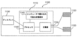
[0028] センサストリップを挿入するのに適合した手持ち型測定装置は、サンプル中の分析目的物の濃度を決定するために提供される。装置には、接点と、少なくとも1つのディスプレイと、接点およびディスプレイの間に電気的連絡が確立している電気回路とが含まれる。回路には、充電器およびプロセッサが含まれ、プロセッサはコンピュータで読み込み可能な記憶媒体と電気的に連絡している。媒体には、コンピュータで読み込み可能なソフトウェアコードが含まれ、このソフトウェアコードはプロセッサによって実行されたときに、充電器が接点間で180秒以内に少なくとも3回の負荷サイクルを含んでいるパルスシークエンスの実行を引き起こす。 [0028] A hand-held measuring device adapted to insert a sensor strip is provided for determining the concentration of an analyte of interest in a sample. The apparatus includes a contact, at least one display, and an electrical circuit in which electrical communication is established between the contact and the display. The circuitry includes a charger and a processor, which is in electrical communication with a computer readable storage medium. The medium includes computer readable software code that, when executed by the processor, is a pulse sequence that includes at least three duty cycles within 180 seconds between the contacts of the charger. Cause execution.
[0029] 測定されたサンプル中の分析目的物の濃度における、メディエータバックグラウンドに起因しうるバイアスを減少させる方法であって、サンプルに180秒以内に少なくとも3回の負荷サイクルを含んでいるパルスシークエンスを印加することを含む方法が提供される。 [0029] A method for reducing bias in a measured sample concentration that can be attributed to mediator background, wherein the sample comprises at least three duty cycles within 180 seconds Is provided.
[0030] サンプル中の分析目的物の濃度を決定するための、180秒以内に少なくとも3回の負荷サイクルを含んでいるパルスシークエンスの持続時間を決定する方法であって、少なくとも3回の負荷サイクルのあいだ記録される電流から決定される複数組の較正定数を決定すること、および決定されたサンプル中の分析目的物の濃度に応じたパルスシークエンスの持続時間を決定することが含まれる前記方法が提供される。 [0030] A method for determining the duration of a pulse sequence comprising at least 3 duty cycles within 180 seconds for determining the concentration of an analyte of interest in a sample, comprising at least 3 duty cycles Said method comprising determining a plurality of sets of calibration constants determined from currents recorded during a period of time, and determining a duration of the pulse sequence as a function of the determined concentration of the analyte in the sample. Provided.
[0031] 使用者に信号を出してセンサストリップに追加サンプルを加える方法であって、ゲート化電流測定パルスシークエンスのあいだ記録された電流から減衰定数を決定することにより、センサストリップが充填量不足かどうかを決定すること、およびストリップが充填量不足であれば使用者に信号を出してセンサストリップに追加サンプルを加えることが含まれる前記方法が提供される。 [0031] A method of signaling the user and adding additional samples to the sensor strip, whether the sensor strip is underfilled by determining an attenuation constant from the current recorded during the gated amperometric pulse sequence. A method is provided that includes determining if and if the strip is underfilled, signaling the user to add additional samples to the sensor strip.
[0032] センサストリップに含まれるサンプルの温度を決定する方法であって、ゲート化電流測定パルスシークエンスで記録された電流から減衰定数を決定すること、および減衰定数が温度と相関させることが含まれる前記方法が提供される。 [0032] A method for determining the temperature of a sample contained in a sensor strip, comprising determining an attenuation constant from current recorded in a gated amperometric pulse sequence, and correlating the attenuation constant with temperature. The method is provided.
[0033] サンプル中の分析目的物の濃度を決定するためのパルスシークエンスの持続時間を決定する方法であって、ゲート化電流測定パルスシークエンスのあいだ記録された電流から決定された減衰定数により、センサストリップに含まれるサンプルの温度を決定することが含まれる前記方法が提供される。 [0033] A method for determining the duration of a pulse sequence for determining the concentration of an analyte of interest in a sample, wherein the sensor uses a decay constant determined from the current recorded during a gated amperometric pulse sequence. The method is provided including determining the temperature of a sample contained in the strip.
[0034] 以下の定義は、明細書および請求範囲の明確で一貫した理解を提供するために付加される。
[0035] 「分析目的物」という用語は、サンプル中に存在する一種類または複数種類の物質として定義される。分析は、サンプル中に存在する分析目的物の存在および/または濃度を決定する。
[0034] The following definitions are added to provide a clear and consistent understanding of the specification and claims.
[0035] The term "analytical object" is defined as one or more substances present in a sample. Analysis determines the presence and / or concentration of the analyte of interest present in the sample.
[0036] 「サンプル」という用語は、未知量の分析目的物を含んでもよい組成物として定義される。通常、電気化学的分析に用いられるサンプルは液状であり、また好ましくは、サンプルは水溶性混合物である。サンプルは、血液、尿、または唾液などの、生物学的サンプルであってもよい。サンプルはまた、抽出物、希釈液、ろ過液、または再構成された沈殿などの、生物学的サンプルの誘導体であってもよい。 [0036] The term "sample" is defined as a composition that may contain an unknown amount of an analyte of interest. Typically, the sample used for electrochemical analysis is liquid and preferably the sample is an aqueous mixture. The sample may be a biological sample, such as blood, urine, or saliva. The sample may also be a derivative of a biological sample, such as an extract, diluent, filtrate, or reconstituted precipitate.
[0037] 「測定可能種」という用語は、適切な電位において、電気化学的センサストリップの作用電極で酸化または還元されうる、電気化学的に活性のある種として定義される。測定可能種の例には、分析目的物、酸化還元酵素およびメディエータが含まれる。 [0037] The term "measurable species" is defined as an electrochemically active species that can be oxidized or reduced at the working electrode of an electrochemical sensor strip at an appropriate potential. Examples of measurable species include analytes, oxidoreductases and mediators.
[0038] 「電流測定」という用語は、サンプル中の分析目的物の濃度が、ある電位で分析目的物の酸化率または還元速度を電気化学的に測定することによって決定される、分析方法として定義される。 [0038] The term "current measurement" is defined as an analytical method in which the concentration of an analyte in a sample is determined by electrochemically measuring the oxidation rate or reduction rate of the analyte at a certain potential. Is done.
[0039] 「システム」または「センサシステム」という用語は、伝導体を通じて測定装置と電気的に連絡するセンサストリップとして定義され、測定装置はサンプル中の分析目的物の濃度を定量することができる。 [0039] The term "system" or "sensor system" is defined as a sensor strip that is in electrical communication with a measurement device through a conductor, and the measurement device is capable of quantifying the concentration of an analyte of interest in a sample.
[0040] 「センサストリップ」という用語は、分析の過程でサンプルを含み、そしてサンプルと測定装置の間で電気的な連絡を提供する装置として定義される。サンプルを含むセンサストリップ部はしばしば、「キャップ−ギャップ」と呼ばれる。 [0040] The term "sensor strip" is defined as a device that contains a sample in the course of analysis and provides electrical communication between the sample and a measuring device. The sensor strip portion containing the sample is often referred to as a “cap-gap”.
[0041] 「伝導体」という用語は、電気化学的分析中に安定的な、電気的に伝導性のある物質として定義される。
[0042] 「測定装置」という用語は、センサストリップの伝導体に電位を印加し、そして生じた電流を測定しうる、一種類または複数種類の電気的装置として定義される。測定装置にはまた、記録された電流値に応じて、一種類または複数種類の分析目的物の存在および/または濃度を決定する処理能力を含まれていてもよい。
[0041] The term "conductor" is defined as an electrically conductive material that is stable during electrochemical analysis.
[0042] The term "measuring device" is defined as one or more types of electrical devices that can apply a potential to a conductor of a sensor strip and measure the resulting current. The measuring device may also include a processing capability for determining the presence and / or concentration of one or more analytes depending on the recorded current value.
[0043] 「正確性」という用語は、センサストリップによって測定された分析目的物の量が、サンプル中の真の分析目的物の量にどれだけ近いかとして定義される。一つの態様では、正確性はバイアスとい用語で表されてもよい。 [0043] The term "accuracy" is defined as how close the amount of analyte measured by the sensor strip is to the amount of true analyte in the sample. In one embodiment, accuracy may be expressed in terms of bias.
[0044] 「精度」という用語は、同一のサンプルに対して分析目的物の複数回測定が、どれだけ近いかとして定義される。一つの態様では、精度は、複数回の測定間での広がりまたは分散という用語で表されてもよい。 [0044] The term "accuracy" is defined as how close multiple measurements of an analyte are to the same sample. In one aspect, accuracy may be expressed in terms of spread or dispersion between multiple measurements.
[0045] 「酸化還元反応」という用語は、少なくとも1つの電子が最初の種から次の種へと移動することを含む、2つの種の間での化学反応として定義される。したがって、酸化還元反応には酸化および還元が含まれる。反応の酸化半電池は、最初の種による少なくとも1つの電子の損失を含み、一方、還元半電池は、二番目の種へ少なくとも1つの電子の添加を含む。酸化された種のイオン電荷は、除去された電子数と等しい量によって、より正になる。同様に、還元された種のイオン電荷は、得た電子数と等しい量によって、より正ではなくなる。 [0045] The term "redox reaction" is defined as a chemical reaction between two species that involves the transfer of at least one electron from the first species to the next species. Accordingly, the oxidation-reduction reaction includes oxidation and reduction. The oxidation half-cell of the reaction includes the loss of at least one electron by the first species, while the reduction half-cell includes the addition of at least one electron to the second species. The ionic charge of the oxidized species becomes more positive by an amount equal to the number of electrons removed. Similarly, the ionic charge of the reduced species becomes less positive by an amount equal to the number of electrons obtained.
[0046] 「メディエータ」という用語は、酸化または還元されていてもよく、また1つ以上の電子を移動しうる物質として定義される。メディエータは、電気化学的分析での試薬であり、また関心の対象となる分析目的物ではないが、分析目的物の間接的な測定を提供する。単純化したシステムにおいては、メディエータは、分析目的物の酸化または還元に応じた酸化還元反応を受ける。酸化または還元されたメディエータはその後、センサストリップの作用電極で逆の反応を受け、そして最初の酸化数へと再生される。 [0046] The term "mediator" is defined as a substance that may be oxidized or reduced and that may transfer one or more electrons. A mediator is a reagent in an electrochemical analysis and is not the analyte of interest of interest, but provides an indirect measurement of the analyte. In a simplified system, the mediator undergoes a redox reaction in response to the oxidation or reduction of the analyte. The oxidized or reduced mediator is then subjected to the reverse reaction at the working electrode of the sensor strip and regenerated to the initial oxidation number.
[0047] 「結合剤」という用語は、試薬との化学的適合性を持ちながら、試薬への物理的な支持体および封じ込めを供給する物質として定義される。
[0048] 「メディエータバックグラウンド」という用語は、内在の分析目的物の濃度に応答しない測定可能種に起因しうる、測定された分析目的物の濃度に導入されたバイアスとして定義される。
[0047] The term "binder" is defined as a substance that provides physical support and containment to a reagent while having chemical compatibility with the reagent.
[0048] The term "mediator background" is defined as a bias introduced into a measured analyte concentration that can be attributed to a measurable species that does not respond to the concentration of the underlying analyte.
[0049] 「充填量不足」という用語は、センサストリップに注入されたサンプル量が、正確な分析をするには不十分である場合として定義される。
[0050] 「酸化還元対」という用語は、異なる酸化数を持つ化学物質の2つの共役種として定義される。より高い酸化数を持つ種の還元は、より低い酸化数を持つ種を生じる。逆に、より低い酸化数を持つ種の酸化は、より高い酸化数を持つ種を生じる。
[0049] The term "underfill" is defined as the amount of sample injected into the sensor strip is insufficient for accurate analysis.
[0050] The term "redox couple" is defined as two conjugated species of chemicals with different oxidation numbers. Reduction of species with higher oxidation numbers yields species with lower oxidation numbers. Conversely, oxidation of a species with a lower oxidation number yields a species with a higher oxidation number.
[0051] 「酸化数」という用語は、原子などの化学種の形式イオン電荷として定義される。(III)などの高い酸化数はより強い正の電荷を帯びており、(II)などの低い酸化数は弱い正の電荷を帯びる。 [0051] The term "oxidation number" is defined as the formal ionic charge of a chemical species such as an atom. High oxidation numbers such as (III) carry a stronger positive charge, while lower oxidation numbers such as (II) carry a weak positive charge.
[0052] 「可溶性酸化還元種」という用語は、酸化または還元されうる物質であって、水1リットルあたり少なくとも1.0グラムのレベルで水(pH 7、25℃)に可溶性の物質として定義される。可溶性酸化還元種には、電場応答性(electro-active)有機分子、有機遷移金属錯体および遷移金属配位錯体が含まれる。「可溶性酸化還元種」という用語からは、金属元素および単独の金属イオン、特に水に不溶性またはわずかにしか溶けないものが除かれる。
[0052] The term "soluble redox species" is defined as a substance that can be oxidized or reduced and is soluble in water (
[0053] 「酸化還元酵素」という用語は、分析目的物の酸化または還元を促進する酵素として定義される。酸化還元酵素は試薬である。酸化還元酵素という用語には、酸素分子が電子受容体となる酸化反応を促進する「オキシダーゼ」;分析目的物が還元されそして酸素分子が分析目的物ではない還元反応を促進する「リダクターゼ」;および酸素分子が電子受容体ではない酸化反応を促進する「デヒドロゲナーゼ」が含まれる。例えば、改訂版のOxford Dictionary of Biochemistry and Molecular Biology(Smith編集、New York: Oxford University Press (1997) 、161, 476, 477および560ページ)を参照されたい。 [0053] The term "oxidoreductase" is defined as an enzyme that promotes the oxidation or reduction of an analyte. An oxidoreductase is a reagent. The term oxidoreductase includes “oxidase” that promotes an oxidation reaction in which oxygen molecules become electron acceptors; “reductase” that promotes a reduction reaction in which the analyte is reduced and oxygen molecules are not the analyte; “Dehydrogenases” that promote oxidation reactions where oxygen molecules are not electron acceptors are included. See, for example, the revised Oxford Dictionary of Biochemistry and Molecular Biology (edited by Smith, New York: Oxford University Press (1997), 161, 476, 477 and 560).
[0054] 「電場応答性有機分子」という用語は、酸化反応または還元反応を受けられる金属を欠失した有機分子として定義される。電場応答性有機分子はメディエータとして機能することができる。 [0054] The term "electric field responsive organic molecule" is defined as an organic molecule lacking a metal that can undergo an oxidation or reduction reaction. The electric field responsive organic molecule can function as a mediator.
[0055] 「OTM錯体」ともいわれる「有機遷移金属錯体」(organotransition metal complex)という用語は、遷移金属が、シグマ結合(遷移金属にシグマ結合した炭素原子の形式電荷は−1)またはパイ結合(遷移金属にパイ結合した炭素原子の形式電荷は0)を通じて少なくとも1つの炭素原子と結合した錯体として定義される。例えば、フェロセンは、2つのシクロペンタジエニル(Cp)環を持つOTM錯体であり、それぞれは2ヶ所のパイ結合および1ヶ所のシグマ結合によって、5個の炭素原子を介して鉄中心に対して結合した。OTM錯体の他の例は、6個のシアノ配位子(6個の配位子の各形式電荷は−1)が、炭素原子を介して鉄中心にシグマ結合しているフェリシアン化物(III)およびその還元型であるフェロシアン化物(II)である。 [0055] The term "organotransition metal complex", also referred to as "OTM complex", means that the transition metal has a sigma bond (the formal charge of the carbon atom sigma bonded to the transition metal is -1) or a pi bond ( The formal charge of a carbon atom pi-bonded to a transition metal is defined as a complex bound to at least one carbon atom through 0). For example, ferrocene is an OTM complex with two cyclopentadienyl (Cp) rings, each with two pi bonds and one sigma bond to the iron center via five carbon atoms. Combined. Another example of an OTM complex is ferricyanide (III, in which six cyano ligands (each formal charge of the six ligands is -1) are sigma-bonded to the iron center via a carbon atom. ) And its reduced form, ferrocyanide (II).
[0056] 「配位錯体」という用語は、正八面体型、または平面正方型などの、よく知られている配位構造を有する錯体として定義される。結合様式によって定義されているOTM錯体とは異なり、配位錯体は構造によって定義される。したがって、配位錯体はOTM錯体(前述したフェリシアン化物など)であってもよく、または窒素、硫黄、酸素およびリンを含むヘテロ原子のような、炭素以外の非金属原子が遷移金属中心に配位結合している錯体であってもよい。例えば、ルテニウムヘキサアミンは6個のNH3配位子(6個の配位子の各形式電荷は0)がルテニウム中心に配位結合している、よく知られた正八面体構造を有する配位錯体である。有機遷移金属錯体、配位錯体および遷移金属結合についてのより完全な考察は、Collmanら、Principles and Applications of Organotransition Metal Chemistry (1987) および Miessler & TarrのInorganic Chemistry (1991)で見られるであろう。 [0056] The term "coordination complex" is defined as a complex having a well-known coordination structure such as a regular octahedral type or a planar square type. Unlike OTM complexes, which are defined by their binding mode, coordination complexes are defined by their structure. Thus, the coordination complex may be an OTM complex (such as the ferricyanide described above) or a non-metallic atom other than carbon, such as a heteroatom containing nitrogen, sulfur, oxygen and phosphorus, is coordinated to the transition metal center. It may be a complex having a coordinate bond. For example, ruthenium hexaamine has a well-known octahedral structure in which six NH 3 ligands (each of the six ligands has 0 formal charge) are coordinated to the ruthenium center. It is a complex. A more complete discussion of organic transition metal complexes, coordination complexes and transition metal bonds may be found in Collman et al., Principles and Applications of Organotransition Metal Chemistry (1987) and Miessler &Tarr's Inorganic Chemistry (1991).
[0057] 「定常状態」という用語は、独立した入力変数(電圧または時間)に関する電気化学的信号(電流)の変化が、±10または±5%以内などの、実質的に定常である場合として定義される。 [0057] The term "steady state" is used when the change in electrochemical signal (current) with respect to an independent input variable (voltage or time) is substantially steady, such as within ± 10 or ± 5%. Defined.
[0058] 「一過性ポイント」という用語は、伝導体表面への測定可能種の拡散の増加速度が、拡散の比較的一定な速度へと移行する場合での時間の関数として得られた電流値として定義される。一過性ポイント前に、電流は時間とともに急速に変化する。同様に、一過性ポイント後では、電流減衰速度は比較的一定になり、したがって測定可能種の伝導体表面への拡散の比較的一定な速度を反映する。 [0058] The term "transient point" refers to the current obtained as a function of time when the rate of increase of the diffusion of measurable species to the conductor surface transitions to a relatively constant rate of diffusion. Defined as a value. Prior to the transient point, the current changes rapidly with time. Similarly, after the transient point, the current decay rate becomes relatively constant, thus reflecting a relatively constant rate of diffusion of measurable species to the conductor surface.
[0059] 「比較的一定」という用語は、電流値または拡散速度の変化が±20、±10または±5%以内である場合として定義される。
[0060] 「平均初期厚」という用語は、液体サンプルを導入する前の層の平均厚についていう。平均という用語が用いられるのは、上部表面層が凸面と凹面を持ち、平坦ではないためである。
[0059] The term "relatively constant" is defined as the change in current value or diffusion rate is within ± 20, ± 10, or ± 5%.
[0060] The term "average initial thickness" refers to the average thickness of the layer before introducing the liquid sample. The term average is used because the top surface layer has convex and concave surfaces and is not flat.
[0061] 「酸化還元強度」(redox intensity; RI)という用語は、パルスシークエンスのための総励起時間および総緩和遅延時間の合計によって割り算された総励起時間として定義される。 [0061] The term "redox intensity (RI)" is defined as the total excitation time divided by the sum of the total excitation time and the total relaxation delay time for the pulse sequence.
[0062] 「手持ち型装置」という用語は、人間の手で持つことができる装置として定義され、携帯型である。手持ち型装置の一例は、Bayer HealthCare LLC社(Elkhart, IN)から販売されているAscensia(登録商標)Elite血糖値モニタリングシステムに付随した測定装置である。 [0062] The term "handheld device" is defined as a device that can be held by a human hand and is portable. An example of a hand-held device is a measurement device associated with the Ascensia® Elite blood glucose monitoring system sold by Bayer HealthCare LLC (Elkhart, IN).
[0063] 「上」(on)という用語は、「上方」(above)として定義され、そして記載された物質の配向に関連している。例えば、もし第一エレメントが第二エレメントの少なくとも一部の上に沈着する場合、第一エレメントは第二エレメントの「上に沈着」した、と言われる。他の例では、もし第一エレメントが第二エレメントの少なくとも一部の上方に存在する場合、第一エレメントは第二エレメント「上」にある、と言われる。「上」(on)という用語の使用は、記載される上部エレメントと下部エレメントとの間に物質が存在することを除外しない。例えば、第一エレメントは上部表面をコーティングされていてもよいが、第一エレメントの少なくとも一部の上のに第二エレメントおよびその上部表面コーティングは、第一エレメントの「上」(on)として記載されてもよい。したがって、「上」(on)という用語の使用は関連づけられる2つのエレメントが物理的に接触していることを意味してもよく、または意味しなくてもよい。 [0063] The term "on" is defined as "above" and relates to the orientation of the material described. For example, if the first element is deposited on at least a portion of the second element, the first element is said to have “deposited on” the second element. In another example, a first element is said to be “on” the second element if the first element is present above at least a portion of the second element. The use of the term “on” does not exclude the presence of material between the upper and lower elements described. For example, the first element may be coated on the top surface, but the second element and its top surface coating on at least a portion of the first element are described as “on” the first element. May be. Thus, the use of the term “on” may or may not mean that the two associated elements are in physical contact.
発明の詳細な説明
[0082] 本発明は、複数の負荷サイクルを含むゲート化電流測定パルスシークエンスが、分析完了時間を減少させながら、分析の正確性および精度の改善を提供することができる、という知見を使用する。各負荷サイクルには、比較的定電圧で提供することができる励起が含まれる。各負荷サイクルにはまた、開回路によって提供することができる緩和が含まれる。本発明のパルスシークエンスは、付加的な遅延およびパルス、例えば試薬の再水和を提供するための「インキュベーション」遅延、電極を回復するための「バーンオフ」パルス、ならびにメディエータの酸化状態を回復するためのメディエータ再生パルスなど、の必要性を除去することにより、分析に必要とされる時間を減少させることができる。
Detailed Description of the Invention
[0082] The present invention uses the finding that a gated amperometric pulse sequence that includes multiple duty cycles can provide improved accuracy and precision of the analysis while reducing analysis completion time. Each duty cycle includes an excitation that can be provided at a relatively constant voltage. Each duty cycle also includes a relaxation that can be provided by an open circuit. The pulse sequence of the present invention provides additional delays and pulses, eg, “incubation” delays to provide reagent rehydration, “burn-off” pulses to restore the electrode, and mediator oxidation state to be restored. By removing the need for such mediator regeneration pulses, the time required for analysis can be reduced.
[0083] 短い分析時間であっても、本発明のゲート化電流測定パルスシークエンスは従来の方法と比較すると、正確性および/または精度を改善することができる。一つの態様では、ヘマトクリット効果により導入される正確性の誤差およびさまざまなキャップ−ギャップ容積により導入される精度の誤差は、本発明のパルスシークエンスと拡散バリア層とを組み合わせることによって減少させることができる。他の態様では、本発明によらなければ非定常状態のセンサ条件および/またはメディエータバックグラウンドによって生じる誤差を、減少させることができる。本発明のゲート化パルスシークエンスはまた、一過性電流の測定および定常状態の条件をシミュレートする輪郭特性の測定を可能にする。一過性電流特性を使用して、複数組の較正定数、充填量の不足の検出、および測定装置からの温度に依存する代わりにサンプル温度を検出する能力、を提供することができる。 [0083] Even with short analysis times, the gated amperometric pulse sequence of the present invention can improve accuracy and / or accuracy as compared to conventional methods. In one embodiment, the accuracy error introduced by the hematocrit effect and the accuracy error introduced by the various cap-gap volumes can be reduced by combining the pulse sequence of the present invention with a diffusion barrier layer. . In other aspects, errors caused by non-steady state sensor conditions and / or mediator background otherwise can be reduced. The gated pulse sequence of the present invention also allows the measurement of transient currents and the measurement of contour characteristics that simulate steady state conditions. The transient current characteristic can be used to provide multiple sets of calibration constants, detection of underfill and the ability to detect sample temperature instead of relying on temperature from the measurement device.
[0084] 図1Aおよび図1Bは、本発明で使用することができるセンサストリップ100を表す。図1Aは、孔130、凹面領域140および投入端部開口部150を含むフタ120によって、少なくとも一部が覆われたセンサ基板110を含む、組み立てられたセンサストリップ100の透視図である。部分的に封入された容積160(キャップ−ギャップ)は、基板110およびフタ120の間に形成される。本発明に適合性のある他のセンサストリップのデザインも使用することができ、これらは米国特許番号5,120,420 号および5,798,031号に記載されているようなものである。
[0084] FIGS. 1A and 1B represent a
[0085] 分析を行う液体サンプルを、開口部150に導入することによってキャップ−ギャップ160に輸送することができる。容器内にたまっていた空気を孔130から排出しつつ、液体がキャップ−ギャップ160に充填される。キャップ−ギャップ160は、キャップ−ギャップ中の液体サンプルの保持を補助する組成物(非掲載)を含んでもよい。このような組成物の例には、カルボキシメチルセルロースおよびポリエチレングリコールなどの水分で膨張できる重合体;および、デキストランやポリアクリルアミドなどの多孔性重合体マトリクスが含まれる。
[0085] The liquid sample to be analyzed can be transported to the cap-
[0086] 図1Bはフタ120を取り外した状態のセンサストリップ100の上面図を表す。伝導体170および180は、それぞれ、誘電体層190の下で、開口部150から作用電極175および対電極185に走行してもよい。一つの態様では、作用電極175および対電極185は、図に示されるように、実質的に同一面上にあってもよい。関連のある態様では、作用電極175および対電極185は、200または250μm以上の間隔で離れていてもよく、またフタ120の上部からは少なくとも100μm離れていてもよい。誘電体層190は、電極175、185を部分的に覆っていてもよく、また絶縁重合体などの適した誘電体物質から作成されてもよい。
FIG. 1B shows a top view of the
[0087] 対電極185は、センサストリップ100の作用電極175での電位とつり合っている。一つの態様では、この電位は、銀/塩化銀などの酸化還元対から対電極185を形成して、参照電極−対電極の組み合わせを提供することによって達成した参照電位であってもよい。他の態様では、電位は、キャップ−ギャップ160中に、炭素などの不活性物質から対電極185を形成することやフェリシアン化物などの可溶性酸化還元種を含ませることによってセンサシステムに提供されてもよい。あるいは、センサストリップ100は、第三伝導体および電極(非掲載)を提供して、センサシステムへ参照電位を提供してもよい。
The
[0088] 図2は、作用電極175および対電極185の層構造を示す図1Bで表されたセンサストリップの断面図を表す。伝導体170および180は、基板110に直接載っていてもよい。表面伝導体層270および280は、それぞれ伝導体170および180上に固着されていてもいなくてもよい。表面伝導体層270および280は、同じ物質から作製されても、または異なる物質から作製されてもよい。
FIG. 2 represents a cross-sectional view of the sensor strip depicted in FIG. 1B showing the layer structure of the working
[0089] 伝導体170、180および表面伝導体層270、280を形成するために用いられる一種類または複数種類の物質には、どのような伝導体が含まれていてもよい。好ましい伝導体は、非イオン化のものであり、それによりこの物質はサンプルの分析中に正味の酸化または正味の還元を受けない。伝導体170、180には、好ましくは、金属ペーストの薄層または、金、銀、白金、パラジウム、銅またはタングステンなどの金属が含まれる。表面伝導体層270、280には、好ましくは、炭素、金、白金、パラジウム、またはこれらの組み合わせが含まれる。もし表面伝導体層が伝導体上に存在しない場合、伝導体は非イオン化物質から作成されるのが好ましい。
[0089] The
[0090] 表面伝導体物質は、金属箔固着、化学蒸着、スラリー固着などを含む、センサストリップの操作に適合性のあるどのような従来からの手段によって処理されてもよい。スラリー固着のケースでは、混合物を、米国特許番号5,798,031号に記載されるように、インクとして伝導体170、180に適用してもよい。
[0090] The surface conductor material may be processed by any conventional means compatible with the operation of the sensor strip, including metal foil bonding, chemical vapor deposition, slurry bonding, and the like. In the case of slurry adhesion, the mixture may be applied as an ink to
[0091] 試薬層275および285は、それぞれ伝導体170および180に沈着されていてもよく、それらには試薬および場合によっては結合剤を含んでもよい。結合剤物質は、好ましくは、少なくとも部分的には水溶性の重合体物質である。結合剤として使用されるのに適した部分的水溶性重合体物質には、ポリ(エチレンオキシド)(PEO)、カルボキシメチルセルロース(CMC)、ポリビニルアルコール(PVA)、ヒドロキシエチレンセルロース(HEC)、ヒドロキシプロピルセルロース(HPC)、メチルセルロース、エチルセルロース、エチルヒドロキシエチルセルロース、カルボキシメチルエチルセルロース、ポリビニルピロリドン(PVP)、ポリリジンなどのポリアミノ酸、ポリスチレンスルホン酸、ゼラチン、アクリル酸、メタクリル酸、デンプン、これらの無水マレイン酸塩、これらの誘導体、およびこれらの組み合わせが含まれる。上述した結合剤物質の中でも、PEO、PVA、CMCおよびPVAが好ましく、現在のところさらにCMCとPEOが本発明にはより好ましい。
[0091] Reagent layers 275 and 285 may be deposited on
[0092] 結合剤に加えて、試薬層275および285には、同じ試薬または異なる試薬が含まれてもよい。一つの態様では、第一層275に存在する試薬は、作用電極175との使用のために選抜されてもよく、一方で第二層285に存在する試薬は、対電極185との使用のために選抜されてもよい。例えば、層285中の試薬は、サンプルと伝導体180との間での電子の自由な流れを促進することができる。同様に、層275中の試薬は、分析目的物の反応を促進することができる。
[0092] In addition to the binder, the reagent layers 275 and 285 may include the same reagent or different reagents. In one embodiment, the reagent present in the
[0093] 試薬層275は、分析目的物、特に複雑な生物学的サンプル中のもの、に対するセンサシステムの特異性を増強しながら、分析目的物の反応を促進できる、分析目的物に特異的な酸化還元酵素を含んでもよい。いくつかの特異的な酸化還元酵素および対応する分析目的物の例は、以下の表IIに示される。
[0093] The
現時点では、グルコース分析に特に好ましい酸化還元酵素には、グルコースオキシダーゼ、グルコースデヒドロゲナーゼ、これらの誘導体、またはこれらの組み合わせが含まれる。 Currently, particularly preferred oxidoreductases for glucose analysis include glucose oxidase, glucose dehydrogenase, derivatives thereof, or combinations thereof.
[0094] 試薬層275にはまた、表面伝導体270および/または伝導体170へ、分析目的物反応の結果をより効率よく伝達するためのメディエータが含まれてもよい。メディエータの例には、OTM錯体、配位錯体および電気活性のある有機分子が含まれる。特異的な例は、フェロセン化合物、フェロシアン化物、フェリシアン化物、置換型または非置換型ピロロキノリンキノン(PQQ)の補酵素、置換型または非置換型3フェニルイミノ-3H-フェノチアジン類(PIPT)、3-フェニルイミノ-3H-フェノキサジン(PIPO)、置換型または非置換型ベンゾキノン類、置換型または非置換型ナフトキノン類、Nオキシド類、ニトロソ化合物、ヒドロキシルアミン類、オキシン類、フラビン類、フェナジン類、フェナジン誘導体、フェノチアジン類、インドフェノール類およびインダミン類が含まれる。試薬層に含まれてもよい、これらの、および他のメディエータは、米国特許番号5,653,863、5,520,786、4,746,607、3,791,988号および欧州特許番号0 354 441号および0 330 517号中に見いだすことができる。
[0094] The
[0095] 現在のところ、グルコース分析に特に好ましいメディエータには、フェリシアン化物、ルテニウムヘキサアミン、PIPT、PIPOまたはこれらの組み合わせが含まれる。生物学的酸化還元システムに有用な電気化学的メディエータの概説は、Analytica Clinica Acta.誌140 巻(1982年)、1-18ページに見いだすことができる。 [0095] Currently, particularly preferred mediators for glucose analysis include ferricyanide, ruthenium hexaamine, PIPT, PIPO or combinations thereof. An overview of electrochemical mediators useful in biological redox systems can be found in Analytica Clinica Acta. Volume 140 (1982), pages 1-18.
[0096] 試薬層275、285は、印刷法、液体沈着法、またはインクジェット沈着法などの、どのような簡便な手段によって沈着されてもよい。一つの態様では、試薬層は印刷法によって沈着される。他の要因と同様に、印刷ブレードの角度は試薬層の厚みに逆に影響しうる。例えば、ブレードが基板110に対しておよそ82°の角度で移動した場合、試薬層はおよそ10μmの厚さとなる可能性がある。同様に、ブレード角が基板110に対しておよそ62°で用いられた場合、より厚めの30μmの試薬層が産生される。したがって、より小さいブレード角によって、より厚い試薬層を提供しうる。ブレード角に加え、スクリーンサイズやエマルジョンの組み合わせと同様に、適用される物質の粘性などの、その他の要因が、試薬層275、285の厚みに影響を及ぼしうる。
[0096] The reagent layers 275, 285 may be deposited by any convenient means such as printing, liquid deposition, or ink jet deposition. In one embodiment, the reagent layer is deposited by a printing method. As with other factors, the angle of the printing blade can adversely affect the thickness of the reagent layer. For example, if the blade is moved at an angle of approximately 82 ° with respect to the
[0097] 作用電極175にはまた、拡散バリア層(DBL)を含んでもよく、これは試薬層275に必須であるか、または図2で表されているような別の層290である。したがって、DBLは伝導体上の組み合わせ試薬/DBLとして、伝導体上の別の層として、または試薬層上の別の層として、形成することができる。作用電極175に別のDBL290が含まれる場合、試薬層275はDBL290上にあってもよく、またはなくてもよい。DBL290上にあるかわりに、試薬層275はセンサストリップ100のどの部分上にあってもよく、それによりサンプル中に試薬を可溶化することができる。例えば、試薬層175は、基板110上またはフタ120にあってもよい。
[0097] The working
[0098] DBLは、測定可能種が存在できる内部容積を有する多孔性スペースを提供する。DBLの孔を選抜することができ、それにより測定可能種はDBL中に拡散できるが、赤血球などの、物理的に大きなサンプル中の成分は実質的に除外される。従来のセンサストリップは、作用電極表面から赤血球をふるい分けるためのさまざまな物質を用いてきたが、DBLは内部多孔性スペースを提供することでサンプルから測定可能種の一部を含み、そしてその一部を分離する。 [0098] DBL provides a porous space with an internal volume in which measurable species can reside. DBL pores can be selected so that measurable species can diffuse into the DBL, but components in physically large samples, such as red blood cells, are substantially excluded. While conventional sensor strips have used a variety of materials to screen red blood cells from the working electrode surface, DBL contains some of the measurable species from the sample by providing an internal porous space, and one of them. Separate the parts.
[0099] 試薬層275に水溶性結合剤が含まれる場合には、励起を印加する前のサンプル中には可溶化しない結合剤のどの部分も、必須のDBLとして機能できる。DBL/試薬層の組み合わせの平均初期厚は、好ましくは30または23マイクロメートル(μm)未満であり、より好ましくは16μm未満である。現在のところ、DBL/試薬層の組み合わせの特に好ましい平均初期厚は、1から30μmまたは3から12μmである。DBL/試薬層の組み合わせの望ましい平均初期厚は、DBLから、図2由来の伝導体170の表面または表面伝導体270の表面などの伝導体表面への、測定可能種の拡散速度が比較的一定になった場合に基づき、特異的な励起長に関して選抜されてもよい。
[0099] When the
[00100] その上、DBLから伝導体表面への測定可能種の拡散速度が比較的一定になった場合、短い励起長とともに厚すぎるDBLを用いることは遅延しうる。例えば、0.5秒の緩和で間隔をあけた1秒間の励起を連続的に行うことを含む負荷サイクルを、30μmの平均初期厚を持つDBL/試薬層の組み合わせを使用する作用電極に印加する場合、好ましい拡散速度には、少なくとも6回の負荷サイクルが印加されるまで(10秒以内)には達しない。逆に、同じ負荷サイクルが、11μmの平均初期厚を持つDBL/試薬層の組み合わせを使用する作用電極に印加される場合、比較的一定な拡散速度に、2回目の励起後に(およそ2.5秒)に達しうる。したがって、所定の負荷サイクルでは、DBLの好ましい平均初期厚には上限がある。DBL厚、励起長、比較的一定の拡散速度に達するまでの時間の間の相関についての徹底的な処理は、2005年2月22日出願の「拡散バリア層内での濃度++++++0決定」と題した、米国仮出願番号60/655,180で見られる。 [00100] Moreover, using a DBL that is too thick with a short excitation length can be delayed if the diffusion rate of the measurable species from the DBL to the conductor surface becomes relatively constant. For example, when applying a duty cycle involving continuous excitation for 1 second spaced by 0.5 second relaxation to a working electrode using a DBL / reagent layer combination with an average initial thickness of 30 μm, The preferred diffusion rate is not reached until at least 6 duty cycles are applied (within 10 seconds). Conversely, when the same duty cycle is applied to a working electrode using a DBL / reagent layer combination with an average initial thickness of 11 μm, after a second excitation (approximately 2.5 seconds), a relatively constant diffusion rate Can be reached. Thus, for a given duty cycle, there is an upper limit on the preferred average initial thickness of DBL. A thorough treatment of the correlation between DBL thickness, excitation length, and time to reach a relatively constant diffusion rate can be found in “Concentration in Diffusion Barrier Layer +++++” filed February 22, 2005. Found in US Provisional Application No. 60 / 655,180 entitled “+0 Decision”.
[00101] 別のDBL290には、サンプル中に部分的に溶けるか、または徐々に溶けながら、望ましい孔スペースを提供するようないずれかの材料が含まれてもよい。一つの態様では、別のDBL290には、試薬を欠失している試薬結合剤物質が含まれてもよい。別のDBL290は少なくとも5μm、好ましくは8から25μm、そしてより好ましくは8から15μmの平均初期厚であってもよい。
[00101] Another
[00102] 図3は、サンプル312中の分析目的物322の有無、および場合によっては濃度を決定するための電気化学的分析300を表す。310では、サンプル312は、図1A、図1Bおよび図2で表されるセンサストリップ314に対して導入される。図2での275および/または285などの試薬層はサンプル312中へと溶け込み始めることで、反応が開始する。現在のところ、分析において、初期時間遅延、または試薬がサンプル312と反応するための「インキュベーション時間」を提供するのに有利であると考えられる。好ましくは、初期時間遅延は1から10秒であってもよい。初期時間遅延のより徹底的な処理は米国特許番号5,620,579号および5,653,863号中に見いだすことができる。
[00102] FIG. 3 depicts an
[00103] 反応中、サンプル312に存在する分析目的物322の一部は、320中で、例えば、酸化還元酵素によって、化学的または生化学的に酸化または還元される。酸化または還元時に、電子は330中で分析目的物322およびメディエータ332間を輸送されてもされなくてもよい。 [00103] During the reaction, a portion of the analyte 322 present in the sample 312 is chemically or biochemically oxidized or reduced in 320, for example, by an oxidoreductase. Upon oxidation or reduction, the electrons may or may not be transported between the analyte 322 and the mediator 332 in 330.
[00104] 340では、320由来の荷電された分析目的物322、または330由来の荷電したメディエータ332であってもよい測定可能種342は、電気化学的に励起される(酸化される、または還元される)。例えば、サンプル312が、320中のグルコースオキシダーゼによって酸化されたグルコースを含む全血であり、それにより電子が移動し、330中のフェリシアン化物(III)メディエータをフェロシアン化物(II)へと還元する場合、340の励起は、作用電極においてフェロシアン化物からフェリシアン化物へと酸化する。このように、電子は選択的にグルコース分析目的物からセンサストリップの作用電極へと移動され、そこで測定装置によって検出されることができる。 [00104] At 340, the measurable species 342, which may be a charged analyte 322 from 320, or a charged mediator 332 from 330, is electrochemically excited (oxidized or reduced). ) For example, sample 312 is whole blood containing glucose oxidized by glucose oxidase in 320, thereby transferring electrons and reducing ferricyanide (III) mediator in 330 to ferrocyanide (II). If so, the 340 excitation oxidizes from ferrocyanide to ferricyanide at the working electrode. In this way, the electrons are selectively transferred from the glucose analyte to the working electrode of the sensor strip where they can be detected by the measuring device.
[00105] 励起340から生じた電流を、350での時間の関数として励起340のあいだ記録することができる。360では、サンプルは緩和を受ける。好ましくは、電流は緩和360のあいだは記録されない。
[00105] The current generated from
[00106] 370では、励起340、記録350および緩和360を、180秒またはそれよりも短い時間枠内に、全部で少なくとも3回の負荷サイクルが行われるサイクルのあいだに、少なくとも2回繰り返す。記録された電流および時間の値を分析し、380におけるサンプル312中の分析目的物322の有無および/または濃度を決定できる。
[00106] At 370,
[00107] 電流測定センサシステムは、電流(アンペア数)がモニターされるあいだ、センサストリップへ電位(ボルト数)を印加し、測定可能種を励起する。従来の電流測定センサシステムは、例えば5秒から10秒の、連続的な読み取りパルス長のための電流を測定しながら、電位を維持することができる。従来の方法とは対照的に、電気化学的分析300に用いられる負荷サイクルは、連続的で、長い持続時間の読み取りパルスを、短い持続時間の複数の励起および緩和に、置き換える。
[00107] While the current (amperage) is monitored, the amperometric sensor system applies a potential (volts) to the sensor strip to excite the measurable species. Conventional amperometric sensor systems can maintain the potential while measuring the current for a continuous read pulse length, eg, 5-10 seconds. In contrast to conventional methods, the duty cycle used for
[00108] 分析300は、ストリップのキャップ−ギャップ内に存在する測定可能種とは対照的に、540において作用電極で励起された測定可能種が実質的にDBLの内側からから引き出された場合、分析目的物測定の正確性および/または精度を上げることができる。図4Aおよび図4Bは、長い読み取りパルスおよび短い励起の印加のあいだの、表面伝導体430および別のDBL 405を有する作用電極400を表す。WBサンプルが作用電極400に適用される場合、赤血球420はDBL 405を覆う。サンプル中に存在する分析目的物は、DBL 405の外側に外部測定可能種410を形成する。外部測定可能種410の一部は、別のDBL 405中に拡散し、内部測定可能種415を提供する。
[00108] The
[00109] 図4Aに示されるように、連続的な10秒間の読み取りパルスが作用電極400に印加される場合、外部測定可能種410および内部測定可能種415のどちらも、酸化状態の変化によって表面伝導体430で励起される。長い読み取りパルスの間、外部測定可能種410は、赤血球420が存在するサンプル領域を通じて、またDBL 405を通って表面伝導体430へ拡散する。読み取りパルスの間、赤血球420を介した外部測定可能種410の拡散は、分析にヘマトクリット効果を導入する。表面伝導体430で励起された測定可能種のかなりの部分が、DBL 420の外側から生じるため、DBLを有するセンサストリップに印加された長い読み取りパルスは、DBLを持たないストリップに印加された短い読み取りパルスへのヘマトクリット効果に関して、同様に作用できる。
[00109] As shown in FIG. 4A, when a continuous 10 second read pulse is applied to the working
[00110] 逆に、図4Bは、DBL 405の外側の測定可能種410の励起を実質的に排除しながら、DBLを装備したセンサストリップ400に、短い励起を印加して、内部測定可能種415を励起する状況を表す。短い励起の間、測定可能種410は、DBL 405の外側に残留するか、またはDBLを通って表面伝導体430へと到達する様な拡散を実質的に行わない。このように、短い励起は、分析に対するヘマトクリット効果の影響を実質的に減少させることができる。
[00110] Conversely, FIG. 4B shows that the internal
[00111] 作用電極での励起の長さを調整することによって、DBLの外側の測定可能種を分析から実質的に排除しながら、DBLの内側の測定可能種を分析できる。作用電極の表面伝導体430と関連して、DBL 405の厚さおよび内部容積は、外部測定可能種410の拡散速度と関連して、内部測定可能種415の拡散速度を変化させると考えられる。
[00111] By adjusting the length of excitation at the working electrode, the measurable species inside the DBL can be analyzed while the measurable species outside the DBL are substantially excluded from the analysis. In connection with the working
[00112] DBLの内側の測定可能種は、DBLの外側での測定可能種よりも作用電極の伝導体へ異なる割合で拡散できるため、作用電極での励起の長さにより、どの測定可能種が優先的に分析されるかを選択することができる。分子的な観点からは同一であっても、DBLの内側および外側での異なる拡散速度は区別を可能とする。 [00112] The measurable species inside the DBL can diffuse at different rates into the conductor of the working electrode than the measurable species outside the DBL, so which measurable species depends on the length of excitation at the working electrode. You can choose whether to analyze it preferentially. Even though they are identical from a molecular point of view, different diffusion rates inside and outside the DBL can be distinguished.
[00113] 特定の理論によって拘束されることは望ましくないが、DBLの内部容積から伝導体への測定可能種の拡散速度が比較的一定なのに対し、DBLの外側からDBL内への測定可能種の拡散速度は様々であると考えられている。DBLの外側の測定可能種のさまざまな拡散速度は、サンプル中に存在する赤血球および他の成分によって引き起こされる可能性があり、ヘマトクリット効果を生じる可能性がある。したがって、赤血球を含むサンプルの成分によって起こる分析誤差(バイアス)は、伝導体への比較的一定の拡散速度を有する測定可能種に分析を実質的に制限することによって減少させることができる。 [00113] While not wishing to be bound by any particular theory, the diffusion rate of measurable species from the DBL internal volume to the conductor is relatively constant, whereas the measurable species from outside the DBL into the DBL It is believed that the diffusion rate varies. Various diffusion rates of measurable species outside the DBL can be caused by red blood cells and other components present in the sample, which can result in a hematocrit effect. Thus, analysis errors (bias) caused by sample constituents including red blood cells can be reduced by substantially limiting the analysis to measurable species having a relatively constant rate of diffusion into the conductor.
[00114] DBLの内側の測定可能種を選択的に分析することの他の利点は、さまざまなキャップ−ギャップ容積を有するセンサストリップによる測定の不正確性を減少することである。キャップ−ギャップ内に存在する実質的に全ての測定可能種が分析された場合に、もし読み取りパルスが時間を越えて連続すると、分析はもはやサンプル中の測定可能種の濃度を表せず、代わりにキャップ−ギャップ内の測定可能種の量を決定した;これは、非常に異なる測定値である。励起の長さがキャップ−ギャップの容積に対して長くなるにつれ、電流測定は内在の分析目的物の濃度ではなく、キャップ−ギャップの容積に依存するようになる。したがって、パルス長がキャップ−ギャップ内に存在する測定可能種を「オーバーシュート」する場合、長い読み取りパルスは、分析目的物の濃度に関して非常に不正確な測定値を生じかねない。 [00114] Another advantage of selectively analyzing measurable species inside the DBL is to reduce measurement inaccuracies with sensor strips having various cap-gap volumes. If substantially all measurable species present in the cap-gap are analyzed, if the reading pulse continues over time, the analysis no longer represents the concentration of measurable species in the sample, instead The amount of measurable species within the cap-gap was determined; this is a very different measurement. As the excitation length increases with respect to the cap-gap volume, the amperometry becomes dependent on the cap-gap volume, not the concentration of the underlying analyte. Thus, if the pulse length “overshoots” a measurable species present in the cap-gap, a long read pulse can result in a very inaccurate measurement with respect to the analyte concentration.
[00115] 「拡散バリア層中での濃度測定」と題した2004年10月12日付出願の米国仮出願番号60/617,889で記載されるように、単一の短い読み取りパルスまたは励起を、測定可能種の励起をDBLに実質的に制限するように選択することができる。単一の励起が使用される場合、励起の長さおよびDBLの厚さは、好ましくは、励起のあいだにDBLから伝導体表面への測定可能種が比較的一定な拡散速度へと到達する。励起のあいだに比較的に一定な拡散速度へと到達しない場合、DBL中の測定可能種の濃度は、サンプル中の測定可能種の濃度を正確に表すことができず、したがって分析に悪影響を及ぼす。その上、単一の励起は、メディエータ由来のバックグラウンド信号を効率よく減少させることができない。 [00115] A single short read pulse or excitation can be measured as described in US Provisional Application No. 60 / 617,889, filed October 12, 2004, entitled “Measurement of Concentration in Diffusion Barrier Layer” The species excitation can be chosen to be substantially limited to DBL. If a single excitation is used, the excitation length and DBL thickness preferably reach a relatively constant diffusion rate of the measurable species from the DBL to the conductor surface during the excitation. If a relatively constant diffusion rate is not reached during excitation, the concentration of the measurable species in the DBL cannot accurately represent the concentration of the measurable species in the sample and therefore adversely affects the analysis . Moreover, a single excitation cannot efficiently reduce the mediator-derived background signal.
[00116] 図3を参照すると、励起340、記録350および緩和360は、単一の負荷サイクルから構成され、180秒間またはそれより少ない時間のあいだ、そのサイクルを少なくとも3回センサストリップに対して印加印加することができる。より好ましくは、少なくとも4、6、8、10、14、18または22回の負荷サイクルが、独立的に選択される120、90、60、30、15、10または5秒間のあいだ印加される。一つの態様では、負荷サイクルは、5から60秒間のあいだ印加される。他の態様では、3から18回または3から10回の負荷サイクルを、30秒かそれ以内のあいだ印加することができる。他の態様では、4から8回の負荷サイクルを、3から16秒以内のあいだ印加することができる。
[00116] Referring to FIG. 3,
[00117] 負荷サイクルの励起340の部分の間に印加される電位は、持続時間を通じて、好ましくは実質的に一定の電圧および極性で印加される。このことは、データ記録の間、複数の電位および/または極性を通じて電圧が変化されるか「掃引」される、従来の読み取りパルスと直接的に対比される。一つの態様では、励起340の持続時間は、多くて4秒または5秒であり、また好ましくは、3、2、1.5または1秒未満である。他の態様では、励起340の持続時間は、0.01から3秒、0.01から2秒または0.01から1.5秒である。より好ましくは、励起340の持続時間は0.1から1.2秒である。
[00117] The potential applied during the
[00118] 励起340の後、360では、測定装置はセンサストリップ314を通じて回路を開くことで、システムの緩和を行うことができる。緩和360の間、励起340のあいだ存在する電流は、少なくとも半分、好ましくは10分の1、より好ましくはゼロまで、実質的に減少される。好ましくは、ゼロ電流状態は、開回路または実質的にゼロ電流をもたらすことが当業者に知られている他の方法によってもたらされる。パルスシークエンスの負荷サイクルの間、少なくとも3回の緩和を行うことができる。
[00118] After
[00119] 一つの態様では、緩和360は、少なくとも10、5、3、2、1.5、1または0.5秒の持続時間である。他の態様では、緩和360は、0.1から3秒、0.1から2秒または0.1から1.5秒の持続時間である。より好ましくは、緩和360は0.2から1.5秒の持続時間で、また開回路によってもたらされる。
[00119] In one embodiment, the
[00120] 緩和360の間、イオン化薬剤は分析目的物と反応して、電位の効果なしに付加的な測定可能種を生じうる。したがって、グルコースオキシダーゼおよびフェリシアン化物メディエータを試薬として含むグルコースセンサシステムには、サンプルの分析目的物の濃度に応答性のある付加的なフェロシアン化物(還元メディエータ)を、緩和360の間電位からの干渉なしに産生することができる。
[00120] During
[00121] 多くの従来型の分析方法は、読み取りパルスの持続時間の間、連続的に電圧を印加する。この印可電圧は固定電位を有してもよくあるいは、陽電位から陰電位へ掃引、または陽電位または陰電位から電位に関してゼロ電位へ掃引される電位を有してもよい。ゼロ相対電位であっても、これらの方法は、読み取りパルスの間、センサストリップから連続的に電流を引き出し、それが読み取りパルスを通じて電気化学的反応が連続することを可能とする。したがって、分析目的物の濃度に応じて測定可能種を産生する反応、および作用電極への測定可能種の拡散は、いずれも従来の読み取りパルスのゼロ電位部分のあいだの電流によって影響される。 [00121] Many conventional analytical methods apply voltage continuously for the duration of the read pulse. The applied voltage may have a fixed potential, or may have a potential that is swept from a positive potential to a negative potential, or from a positive potential or a negative potential to a zero potential with respect to the potential. Even at zero relative potential, these methods draw current continuously from the sensor strip during the read pulse, which allows the electrochemical reaction to continue through the read pulse. Thus, both the reaction producing a measurable species as a function of the analyte concentration and the diffusion of the measurable species to the working electrode are influenced by the current during the zero potential portion of a conventional read pulse.
[00122] センサストリップに対して連続的に電圧を印加し、そして電位に関してゼロ電位であってもセンサストリップから電流を引き出す従来の方法は、本発明の緩和とは、基本的に異なる。本発明によって印加された複数の負荷サイクルはまた、本発明の複数の緩和のため、複数の測定での単一の長い持続時間パルスを用いている米国特許番号5,243,516号で開示された従来の方法とは、顕著に異なる。従来の方法とは対照的に、本発明のパルスシークエンスの各負荷サイクルは、緩和の間、非依存的な拡散および分析目的物反応時間を供給する。 [00122] The conventional method of continuously applying a voltage to a sensor strip and drawing current from the sensor strip even with zero potential with respect to the potential is fundamentally different from the relaxation of the present invention. The multiple duty cycles applied by the present invention are also the conventional method disclosed in US Pat. No. 5,243,516 using a single long duration pulse in multiple measurements for the multiple relaxations of the present invention. Is significantly different. In contrast to conventional methods, each duty cycle of the pulse sequence of the present invention provides independent diffusion and analyte reaction time during relaxation.
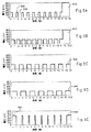
[00123] 図5Aから図5Eは、サンプルの導入後のセンサストリップに複数の負荷サイクルを印加した、ゲート化電流測定パルスシークエンスの5つの例を表す。これらの例では、方形波パルスが用いられた;しかしながら、センサシステムに適合する他の波形およびテストサンプルも用いられてもよい。図5C、図5Dは、同一の励起および開回路遅延時間を有する複数の負荷サイクルを含むパルスシークエンスを表す。 [00123] FIGS. 5A through 5E represent five examples of gated amperometric pulse sequences in which multiple duty cycles are applied to the sensor strip after sample introduction. In these examples, square wave pulses were used; however, other waveforms and test samples that are compatible with the sensor system may also be used. FIGS. 5C and 5D represent pulse sequences including multiple duty cycles with the same excitation and open circuit delay times.
[00124] 図5A、図5Bは、電圧を増加させる、より長い持続時間の終端読み取りパルス510に加え、同一の励起および開回路遅延時間を有する9回の負荷サイクルを含む、パルスシークエンスを表す。この終端読み取りパルスの電圧の増加は、高い酸化電位を有する種を検出する能力を提供する。終端読み取りパルスに関するさらに完全な考察は、「バイオセンサのためのコントロール溶液中の内部基準としての酸化可能種」と題した、2005年4月8日付出願の米国仮出願番号60/669,729中に見いだすことができる。
[00124] FIGS. 5A and 5B represent a pulse sequence that includes nine duty cycles with the same excitation and open circuit delay time in addition to a longer duration
[00125] 図5Aは、0.5秒間の励起が1秒間の開回路遅延によって隔てられ、0.357(5/14)の酸化還元強度(redox intensity: RI)を与える、9回の負荷サイクルのパルスシークエンスを表す。したがって、図5Aでは、二回目の負荷サイクルは励起部分520および緩和部分530とを有する。図5Bは、1秒間の励起が0.5秒間の開回路遅延によって隔てられ、0.69(10/14.5)のRIを与える、9回の負荷サイクルのパルスシークエンスを表す。図5Cは、1秒間の励起が1秒間の開回路遅延によって隔てられ、0.53(8/15)のRIを与える、7回の負荷サイクルパルスシークエンスを表す。7回の負荷サイクルのあいだ用いられたものと同一の持続時間および電圧の終端読み取りパルス540が印加された。図5Dは、1.5秒間の励起が1秒間の開回路遅延によって隔てられ、0.636(10.5/16.5)のRIを与える、6回の負荷サイクルパルスシークエンスを表す。図5Cのように、前の負荷サイクルのパルスと同一の持続時間および電位の終端読み取りパルス540が印加された。図5Eは、相対的に短い0.25秒の励起が相対的に長い1.5秒の緩和によって隔てられている、7回の負荷サイクルパルスシークエンスを表す。図5Eのパルスシークエンスは、最初の1秒のパルス550で開始し、1.25秒の終端読み取りパルスで終了することで、0.25(4/16)のRIを提供する。
[00125] Figure 5A shows a pulse sequence of nine duty cycles, where 0.5 second excitation is separated by 1 second open circuit delay, giving a redox intensity (RI) of 0.357 (5/14). Represent. Thus, in FIG. 5A, the second duty cycle has an
[00126] パルスシークエンスのためのRIが高いほど、メディエータによる分析へ導入されるバックグラウンドがより少なくなる。図5Aから図5Eで表されるパルスシークエンスは、測定可能種である還元メディエータを励起する(すなわち酸化する)ように設計された、酸化的パルスである。したがって、所定の時間内にセンサストリップに印加された酸化電流が大きくなるほど、記録される電流値に寄与する、分析目的物の酸化以外の経路によってメディエータが還元される機会が少なくなる。 [00126] The higher the RI for the pulse sequence, the less background is introduced into the analysis by the mediator. The pulse sequence represented in FIGS. 5A to 5E is an oxidative pulse designed to excite (ie oxidize) the reducing mediator, which is a measurable species. Thus, the greater the oxidation current applied to the sensor strip within a given time, the less chance that the mediator is reduced by a pathway other than the oxidation of the analyte of interest that contributes to the recorded current value.
[00127] 以下の表IIIは、パルスシークエンス(a)および(b)の最後の4回の負荷サイクルの輪郭特性についての傾き、切片および傾きに対する切片の比を示す。パルスシークエンス(a)は:
9×(0.5秒オン + 1.0秒オフ)+ 0.5秒 = 14秒、RI = 5/14 = 0.357.
パルスシークエンス(b)は:
9×(1.0秒オン+ 0.375秒オフ)+ 1.0秒 = 13.375秒、 RI = 10/13.375 = 0.748
である。
[00127] Table III below shows slope, intercept and ratio of intercept to slope for the contour characteristics of the last four duty cycles of pulse sequences (a) and (b). The pulse sequence (a) is:
9 x (0.5 seconds on + 1.0 seconds off) + 0.5 seconds = 14 seconds, RI = 5/14 = 0.357.
The pulse sequence (b) is:
9 x (1.0 seconds on + 0.375 seconds off) + 1.0 seconds = 13.375 seconds, RI = 10 / 13.375 = 0.748
It is.
[00128] 傾きに対する切片の比は、メディエータに寄与するバックグラウンド信号の量の指標を提供し、比がより高いことは、メディエータバックグラウンドに寄与する記録信号の比率がより高いことを示している。したがって、シークエンス(a)および(b)のパルス周波数(励起数/総アッセイ秒数)は約0.7sec-1で同様であるが、パルスシークエンス(b)によって提供されたRIの増加は半分以下のバックグラウンド信号を提供する。組み合わせにおいては、パルスシークエンスの複数の励起は、メディエータの酸化状態を回復するための初期パルスの必要性を除去することができる。バックグラウンド電流は、メディエータによって影響されうるが、フェリシアン化物については、少なくとも0.01、0.3、0.6または1のRI値を有するパルスシークエンスが好ましく、0.1から0.8、0.2から0.7または0.4から0.6のRI値を有するパルスシークエンスがより好ましい。 [00128] The ratio of intercept to slope provides an indication of the amount of background signal contributing to the mediator, with a higher ratio indicating a higher ratio of recording signal contributing to the mediator background. . Thus, the pulse frequency (number of excitations / total assay seconds) of sequences (a) and (b) is similar at about 0.7 sec -1 , but the increase in RI provided by pulse sequence (b) is less than half. Provides a background signal. In combination, multiple excitations of the pulse sequence can eliminate the need for an initial pulse to restore the mediator's oxidation state. Although the background current can be affected by the mediator, for ferricyanides, a pulse sequence with an RI value of at least 0.01, 0.3, 0.6 or 1 is preferred, with RI values of 0.1 to 0.8, 0.2 to 0.7 or 0.4 to 0.6. More preferred is a pulse sequence having
[00129] 図3を再度参照すると、350では、パルスシークエンスの各負荷サイクルのためセンサストリップ314の伝導体を介して通過する電流は、時間の関数として記録することができる。図6Aは、50、100、200、400および600 mg/dLのグルコースを含む、40%ヘマトクリットのWBサンプルについて、図5Bで表されたパルスシークエンスのために時間の関数としてプロットされた出力電流を表す。測定可能種の広範な酸化を生じる従来の長い持続時間の読み取りパルスの代わりに、各励起の後には、電流特性における小休止が続く。 [00129] Referring again to FIG. 3, at 350, the current passing through the conductors of the sensor strip 314 for each duty cycle of the pulse sequence can be recorded as a function of time. Figure 6A shows the output current plotted as a function of time for the pulse sequence represented in Figure 5B for a 40% hematocrit WB sample containing 50, 100, 200, 400 and 600 mg / dL glucose. Represent. Instead of the traditional long duration read pulse that results in extensive oxidation of measurable species, each excitation is followed by a brief pause in current characteristics.
[00130] 図6Aで、出力電流が時間の関数としてプロットされる場合、各励起は、時間とともに減衰する、初期高電流値を有する一過性電流特性を生じる。好ましくは、負荷サイクルには、従来システムの読み取りパルスのあいだに必要とされるような、各励起のあいだで定常状態または緩やかな電流減衰条件に達しないようにシステムを抑制する、短く非依存的な励起および緩和が含まれる。従来の定常状態または緩やかに減衰する電流の代わりに、一過性(急速に減衰する)の電流値がゲート化電流測定パルスシークエンスから得られる。これは作用電極での測定可能種の電気化学的反応が、測定可能種が拡散によって作用電極に供給される速度よりも早いためである。 [00130] In FIG. 6A, when the output current is plotted as a function of time, each excitation results in a transient current characteristic with an initial high current value that decays with time. Preferably, the duty cycle is short and independent, suppressing the system from reaching steady state or gradual current decay conditions during each excitation, as required during conventional system read pulses. Excitation and relaxation are included. Instead of the conventional steady state or slowly decaying current, a transient (rapidly decaying) current value is obtained from the gated amperometric pulse sequence. This is because the electrochemical reaction of the measurable species at the working electrode is faster than the rate at which the measurable species is supplied to the working electrode by diffusion.
[00131] 図6Bは、図6Aで示された、各一過性電流特性由来の最終電流値(すなわち各励起からの最終電流値)をつないだ輪郭特性を示す。輪郭特性が用いられることで、時間の経過につれて電流が変化することが実質的に定常的である、定常状態での従来システムから得られたデータをシミュレートすることができる。 [00131] FIG. 6B shows the contour characteristics connecting the final current values from each transient current characteristic (ie, the final current values from each excitation) shown in FIG. 6A. Contour characteristics can be used to simulate data obtained from a conventional system in a steady state where the current changes substantially over time.
[00132] ゲート化電流測定パルスシークエンスから得られた一過性電流特性および派生した輪郭電流値は、単一の読み取りパルスを用いた従来の分析から得られた電流特性とは、基本的に異なる。単一の読み取りパルスから記録された電流が、単一の緩和/拡散から派生する一方、一過性電流の輪郭特性でのそれぞれの時間の点は、非依存的な緩和/拡散過程後の励起から始まる。さらに、励起の長さが増加するにしたがい、電流と分析目的物の濃度との間の相関は、しばしばヘマトクリット効果のために、減少する可能性がある。したがって、複数の、短い励起を用いた分析の正確性は、組み合わされた複数の励起の持続時間を有するより長い読み取りパルスを用いた分析と比べて、増加する可能性がある。 [00132] Transient current characteristics obtained from gated amperometric pulse sequences and derived contour current values are fundamentally different from current characteristics obtained from conventional analysis using a single read pulse. . While the current recorded from a single read pulse is derived from a single relaxation / diffusion, each time point in the transient current profile is an excitation after an independent relaxation / diffusion process. start from. Furthermore, as the length of excitation increases, the correlation between current and analyte concentration can often decrease due to the hematocrit effect. Thus, the accuracy of an analysis using multiple, short excitations may be increased compared to an analysis using a longer readout pulse with multiple excitation durations combined.
[00133] 図6Aを再度参照すると、励起について得られた最終電流値が全ての励起について得られた最終電流値を表すとき、一過性ポイント605が電流特性に到達する。したがって、図6Aでは、一過性ポイントはおよそ5秒の時点で達している。各グルコース濃度において、DBL再水和に関する平衡を、各グルコース濃度での輪郭特性における最も高い電流値で達成することができる。したがって、図6Aの一過性電流が図6Bの輪郭電流へと変換されるとき、読みとり610(最高値)および620(低値)は、DBLへの測定可能種の拡散および600 mg/dLのグルコース濃度について約5秒でのDBLの再水和に関して、平衡に達したことを立証する。
[00133] Referring again to FIG. 6A, the
[00134] 比較的一定の拡散速度で記録された電流値は、それ以外の方法では再水和での多様性および試薬の拡散速度によって引き起こされうる不正確性を最小化する。したがって、いったん比較的一定の拡散速度に到達すると、記録された電流値は、測定可能種の濃度、そして従って分析目的物の濃度に、より正確に対応する。さらに、図6Bでは、完全な分析がおよそ7秒程度で完結することができ、これはいったん輪郭特性の最高電流値610がわかれば、その値を分析目的物の濃度に直接相関させることができるためである。以前に考察されたように、付加的なデータポイントを得て、メディエータに寄与するバックグラウンド誤差を減少することができる。
[00134] Current values recorded at a relatively constant diffusion rate minimize inaccuracies that could otherwise be caused by diversity in rehydration and reagent diffusion rates. Thus, once a relatively constant diffusion rate is reached, the recorded current value more accurately corresponds to the concentration of the measurable species, and thus the concentration of the analyte of interest. Further, in FIG. 6B, a complete analysis can be completed in about 7 seconds, which can be directly correlated to the concentration of the analyte of interest once the maximum
[00135] 図6Cは、図5Eで表されたパルスシークエンスによって生成された一過性電流特性から調製された電流輪郭特性を表す。各0.25秒の励起のあいだ、電流値は、中央(〜0.125秒)および終わり(〜0.25秒)で記録され、それを使用して減衰定数を決定することができる。短い励起および相対的に長い緩和を伴うより長い初期パルスを用いて、分析を約4秒間内に完了することができる。 [00135] FIG. 6C represents a current profile characteristic prepared from the transient current characteristic generated by the pulse sequence represented in FIG. 5E. During each 0.25 second excitation, the current value is recorded in the middle (˜0.125 seconds) and end (˜0.25 seconds) and can be used to determine the decay constant. The analysis can be completed in about 4 seconds using a longer initial pulse with short excitation and relatively long relaxation.
[00136] 図6Dは、ゲート化電流測定パルスシークエンスを用いて、電気化学的システムについて入力信号に関連する出力信号を図解したグラフである。入力信号は、生物学的な液体のサンプルに印加された電位である。入力信号には、ポーリング入力信号およびアッセイ入力信号が含まれる。出力信号は、サンプルから生成された電流である。出力信号には、ポーリング出力信号およびアッセイ出力信号が含まれる。サンプルは、アッセイ入力信号に応じた全血中のグルコースの酸化還元反応からのアッセイ出力信号を生成する。入力および出力信号は、作用電極および対電極を有するバイオセンサのためのものであってもよい。付加的な電極および異なった形状のバイオセンサを含む、他のバイオセンサを使用することができる。他の生物学的な液体中の分析目的物の濃度を含む、他の分析目的物の濃度を測定することができる。初期に減衰する出力信号、そして全てのパルスで減衰する出力信号を含む、他の出力信号を生成することができる。 [00136] FIG. 6D is a graph illustrating an output signal associated with an input signal for an electrochemical system using a gated amperometric pulse sequence. The input signal is the potential applied to the sample of biological fluid. Input signals include polling input signals and assay input signals. The output signal is a current generated from the sample. The output signals include polling output signals and assay output signals. The sample generates an assay output signal from a redox reaction of glucose in whole blood in response to the assay input signal. The input and output signals may be for a biosensor having a working electrode and a counter electrode. Other biosensors can be used, including additional electrodes and differently shaped biosensors. The concentration of other analytes can be measured, including the concentration of the analyte in other biological fluids. Other output signals can be generated, including an output signal that decays initially and an output signal that decays with every pulse.
[00137] 使用時には、生物学的液体のサンプルをバイオセンサ内に沈着させる。バイオセンサは、サンプルに対してポーリング信号を約−1.25秒から約0秒まで印加する。パルスは、約5-10 msのパルス幅および約125 msのパルス間隔を有する。バイオセンサは、ポーリング入力信号に応じたポーリング出力信号を生成する。バイオセンサは、ポーリング出力信号を測定する。バイオセンサは、アナログコンパレーターの入力に対してポーリング出力信号を提供するポテンショスタットを有してもよい。 [00137] In use, a sample of biological fluid is deposited in the biosensor. The biosensor applies a polling signal to the sample from about −1.25 seconds to about 0 seconds. The pulses have a pulse width of about 5-10 ms and a pulse interval of about 125 ms. The biosensor generates a polling output signal corresponding to the polling input signal. The biosensor measures the polling output signal. The biosensor may have a potentiostat that provides a polling output signal to the input of the analog comparator.
[00138] ポーリング出力信号がポーリング閾値と同程度かまたは高い場合、バイオセンサは、約0秒から約7秒まで電極に対してアッセイ入力信号を印加する。ポーリング閾値バルブは、約250 nAであってもよい。コンパレーターは、ポーリング出力信号をポーリング閾値と比較することができる。ポーリング出力信号がポーリング閾値を超えた時、コンパレーターの出力信号はアッセイ入力信号の開始を誘発することができる。 [00138] If the polling output signal is comparable or higher than the polling threshold, the biosensor applies an assay input signal to the electrode from about 0 seconds to about 7 seconds. The polling threshold valve may be about 250 nA. The comparator can compare the polling output signal with a polling threshold. When the polling output signal exceeds the polling threshold, the comparator output signal can trigger the start of the assay input signal.
[00139] アッセイ入力信号のあいだ、バイオセンサは、約1秒間で約400 mVの電位を持つ第一パルスを伴う負荷サイクルを、作用電極および対電極に対して印加する。第一パルスに引き続いて0.5秒の緩和を行い、それが本質的に開回路などであってもよい。第一パルス中のアッセイ出力信号または電流は、測定され、そして記憶装置に保存される。バイオセンサは、第二パルスを約1秒間、約200 mVで、作用電極および対電極に印加することができる。第二パルス中のアッセイ出力信号または電流は、測定され、そして記憶装置に保存される。バイオセンサは、アッセイ期間の終了までまたはバイオセンサにより必要とされる限り、アッセイ入力信号からのパルスを作用電極および対電極に対して印加し続ける。アッセイ期間は約7秒であってもよい。バイオセンサは、各パルスでのアッセイ出力信号または電流を測定し、そして保存できる。 [00139] During the assay input signal, the biosensor applies a duty cycle with a first pulse having a potential of about 400 mV in about 1 second to the working and counter electrodes. The first pulse may be followed by a 0.5 second relaxation, which may be essentially an open circuit. The assay output signal or current during the first pulse is measured and stored in a storage device. The biosensor can apply a second pulse to the working and counter electrodes for about 1 second at about 200 mV. The assay output signal or current during the second pulse is measured and stored in a storage device. The biosensor continues to apply pulses from the assay input signal to the working and counter electrodes until the end of the assay period or as required by the biosensor. The assay period may be about 7 seconds. The biosensor can measure and store the assay output signal or current at each pulse.
[00140] ポーリング入力信号は、設定した周波数または間隔でパルスを負荷し、またはオン・オフする、電流または電位などの電気信号である。サンプルはポーリング入力信号に応じたポーリング出力信号を生じる。このポーリング出力信号は、電流または電位などの、電気信号である。バイオセンサは、ポーリング出力信号をディスプレイ上に表示することができ、および/またはアッセイ出力信号を記憶装置に保存できる。バイオセンサは、ポーリング信号を印加して、サンプルが電極にいつ接触したかを検出することができる。バイオセンサは、他の方法および装置を用いて、サンプルが分析のためにいつ利用できるかを検出することができる。 [00140] A polling input signal is an electrical signal, such as a current or a potential, that loads or turns on and off a pulse at a set frequency or interval. The sample produces a polling output signal in response to the polling input signal. This polling output signal is an electrical signal such as current or potential. The biosensor can display the polling output signal on a display and / or store the assay output signal in a storage device. The biosensor can apply a polling signal to detect when the sample contacts the electrode. Biosensors can use other methods and devices to detect when a sample is available for analysis.
[00141] ポーリング入力信号は、ポーリングパルスのシークエンスがポーリング緩和によって隔てられた負荷サイクルである。ポーリングパルスの間、電気信号はオンである。ポーリング緩和の間、電気信号はオフである。オンには、電気信号が存在する場合の時間が含まれてもよい。オフには、電気信号が存在しない場合の時間が含まれてもよい。オフには、電気信号が存在するが本質的に振幅を有さない場合の時間が含まれなくてもよい。電気信号は、電気回路を閉じたり開いたりすることで、それぞれオンとオフの間を切り替えることができる。電気回路を、機械的、電気的などで開いたり閉じたりできる。 [00141] The polling input signal is a duty cycle in which the sequence of polling pulses is separated by polling relaxation. During the polling pulse, the electrical signal is on. During polling mitigation, the electrical signal is off. On may include time when an electrical signal is present. Off may include time when no electrical signal is present. Off may not include time when an electrical signal is present but has essentially no amplitude. The electrical signal can be switched between on and off by closing or opening the electrical circuit, respectively. The electrical circuit can be opened and closed mechanically, electrically, etc.
[00142] ポーリング入力信号は一回または複数回のポーリングパルス間隔を有してもよい。ポーリングパルス間隔は、ポーリングパルスおよびポーリング緩和の合計である。各ポーリングパルスは、振幅およびポーリングパルス幅を有する。振幅は、電気信号の電位、電流などの強度を示す。振幅は、ポーリングパルスの間、変化してもよく、または一定であってもよい。ポーリングパルス幅は、ポーリングパルスの持続時間である。ポーリング入力信号におけるポーリングパルス幅は、変化してもよく、または実質的に同じであってもよい。各ポーリング緩和は、ポーリング緩和の持続時間である、ポーリング緩和幅を有する。ポーリング入力信号におけるポーリング緩和幅は、変化してもよく、または本質的に同じであってもよい。 [00142] The polling input signal may have one or more polling pulse intervals. The polling pulse interval is the sum of the polling pulse and polling relaxation. Each polling pulse has an amplitude and a polling pulse width. The amplitude indicates the strength of an electric signal such as a potential or current. The amplitude may vary during the polling pulse or may be constant. The polling pulse width is the duration of the polling pulse. The polling pulse width in the polling input signal may vary or may be substantially the same. Each polling relaxation has a polling relaxation width, which is the duration of the polling relaxation. The polling mitigation width in the polling input signal may vary or may be essentially the same.
[00143] ポーリング入力信号は、約300ミリ秒(ms)未満のポーリングパルス幅、および約1秒未満のポーリングパルス間隔を有してもよい。ポーリング入力信号は、約100 ms未満のポーリングパルス幅、および約500 ms未満のポーリングパルス間隔を有してもよい。ポーリング入力信号は、約0.5 msから約75 msまでの範囲でのポーリングパルス幅、および約5 msから約300 msまでの範囲でのポーリングパルス間隔を有してもよい。ポーリング入力信号は、約1 msから約50 msまでの範囲でのポーリングパルス幅、および約10 msから約250 msまでの範囲でのポーリングパルス間隔を有してもよい。ポーリング入力信号は、約5 msのポーリングパルス幅、および約125 msのポーリングパルス間隔を有してもよい。ポーリング入力信号は、その他のポーリングパルス幅、およびポーリングパルス間隔を有してもよい。 [00143] The polling input signal may have a polling pulse width of less than about 300 milliseconds (ms) and a polling pulse interval of less than about 1 second. The polling input signal may have a polling pulse width of less than about 100 ms and a polling pulse interval of less than about 500 ms. The polling input signal may have a polling pulse width in the range of about 0.5 ms to about 75 ms, and a polling pulse interval in the range of about 5 ms to about 300 ms. The polling input signal may have a polling pulse width in the range of about 1 ms to about 50 ms, and a polling pulse interval in the range of about 10 ms to about 250 ms. The polling input signal may have a polling pulse width of about 5 ms and a polling pulse interval of about 125 ms. The polling input signal may have other polling pulse widths and polling pulse intervals.
[00144] バイオセンサは、ポーリング期間のあいだ、ポーリング入力信号をサンプルに印加することができる。ポーリング期間は、約15分、5分、2分または1分未満であってもよい。ポーリング期間は、使用者がどのようにバイオセンサを用いるかによって、より長くしてもよい。ポーリング期間は、約0.5秒から約15分までの範囲であってもよい。ポーリング期間は、約5秒から約5分までの範囲であってもよい。ポーリング期間は、約10秒から約2分までの範囲であってもよい。ポーリング期間は、約20秒から約60秒までの範囲であってもよい。ポーリング期間は、約30秒から約40秒までの範囲であってもよい。ポーリング期間は、約200回、100回、50回または25回未満のパルス間隔を有してもよい。ポーリング期間は、約2回から約150回までのパルス間隔を有してもよい。ポーリング期間は、約5回から約50回までのパルス間隔を有してもよい。ポーリング期間は、約5回から約15回までのパルス間隔を有してもよい。ポーリング期間は、約10回のパルス間隔を有してもよい。他のポーリング期間を使用してもよい。 [00144] The biosensor can apply a polling input signal to the sample during the polling period. The polling period may be about 15 minutes, 5 minutes, 2 minutes or less than 1 minute. The polling period may be longer depending on how the user uses the biosensor. The polling period may range from about 0.5 seconds to about 15 minutes. The polling period may range from about 5 seconds to about 5 minutes. The polling period may range from about 10 seconds to about 2 minutes. The polling period may range from about 20 seconds to about 60 seconds. The polling period may range from about 30 seconds to about 40 seconds. The polling period may have a pulse interval of less than about 200, 100, 50, or 25 times. The polling period may have a pulse interval of about 2 to about 150 times. The polling period may have a pulse interval of about 5 to about 50 times. The polling period may have a pulse interval of about 5 to about 15 times. The polling period may have about 10 pulse intervals. Other polling periods may be used.
[00145] バイオセンサは、ポーリング出力信号がポーリング閾値と同程度であるか、またはそれより高い場合に、アッセイ入力信号を印加する。ポーリング閾値は、第一パルスの始めに、予想されるアッセイ入力信号の約5パーセント(%)より高くてもよい。ポーリング閾値は、第一パルスの始めに、予想されるアッセイ入力信号の約15パーセント(%)より高くてもよい。ポーリング閾値は、第一パルスの始めに、予想されるアッセイ入力信号の約5パーセント(%)から約50%までの範囲であってもよい。他のポーリング閾値を使用してもよい。バイオセンサは、ポーリング出力信号がディスプレイ上のポーリング閾値と同程度かそれより高いことを示すことができる。 [00145] The biosensor applies the assay input signal when the polling output signal is comparable to or higher than the polling threshold. The polling threshold may be higher than about 5 percent (%) of the expected assay input signal at the beginning of the first pulse. The polling threshold may be higher than about 15 percent (%) of the expected assay input signal at the beginning of the first pulse. The polling threshold may range from about 5 percent (%) to about 50% of the expected assay input signal at the beginning of the first pulse. Other polling thresholds may be used. The biosensor can indicate that the polling output signal is at or above the polling threshold on the display.
[00146] アッセイ入力信号は、設定した周波数または間隔でパルスを負荷しまたはオン・オフする、電流または電位などの電気信号である。サンプルは、アッセイ入力信号に応じたアッセイ出力信号を生じる。アッセイ出力信号は、電流または電位などの電気信号である。 [00146] The assay input signal is an electrical signal, such as current or potential, that loads or turns on and off pulses at a set frequency or interval. The sample produces an assay output signal in response to the assay input signal. The assay output signal is an electrical signal such as current or potential.
[00147] アッセイ入力信号は、アッセイ緩和によって隔てられたアッセイパルスのシークエンスである。アッセイパルスの間、電気信号はオンである。アッセイ緩和の間、電気信号はオフである。オンには、電気信号が存在する場合の期間が含まれる。オフには、電気信号が存在しない場合の時間が含まれ、電気信号が存在するが本質的に振幅を有しない場合の時間は含まれない。電気信号は、電気回路を閉じたり開いたりすることで、それぞれオンとオフの間を切り替える。電気回路を、機械的、電気的などで開いたり閉じたりできる。 [00147] The assay input signal is a sequence of assay pulses separated by assay relaxation. During the assay pulse, the electrical signal is on. During assay relaxation, the electrical signal is off. On includes a period when an electrical signal is present. Off includes time when no electrical signal is present, and does not include time when electrical signal is present but has essentially no amplitude. The electrical signal switches between on and off by closing and opening the electrical circuit, respectively. The electrical circuit can be opened and closed mechanically, electrically, etc.
[00148] アッセイ入力信号は、一回または複数回のアッセイパルス間隔を有してもよい。アッセイパルス間隔は、アッセイパルスとアッセイ緩和との合計である。各アッセイパルスは、振幅およびアッセイパルス幅を有する。振幅は、電気信号の電位、電流などの強度を示す。振幅は、アッセイパルスの間、変化してもよく、または一定であってもよい。アッセイパルス幅は、アッセイパルスの持続時間である。アッセイ入力信号でのアッセイパルス幅は、変化してもよく、または本質的に同じであってもよい。各アッセイ緩和は、アッセイ緩和の持続時間である、アッセイ緩和幅を有する。アッセイ入力信号におけるアッセイ緩和幅は変化してもよく、または本質的に同じであってもよい。 [00148] The assay input signal may have one or more assay pulse intervals. The assay pulse interval is the sum of the assay pulse and the assay relaxation. Each assay pulse has an amplitude and an assay pulse width. The amplitude indicates the strength of an electric signal such as a potential or current. The amplitude may vary during the assay pulse or may be constant. The assay pulse width is the duration of the assay pulse. The assay pulse width at the assay input signal may vary or may be essentially the same. Each assay relaxation has an assay relaxation width, which is the duration of the assay relaxation. The assay relaxation width in the assay input signal may vary or may be essentially the same.
[00149] アッセイ入力信号は、約5秒未満のアッセイパルス幅、および約15秒未満のアッセイパルス間隔を有してもよい。アッセイ入力信号は、約3、2、1.5または1秒未満のアッセイパルス幅、および約13、7、4、3、2.5または1.5秒未満のアッセイパルス間隔を有してもよい。アッセイ入力信号は、約0.1秒から約3秒までの範囲でのアッセイパルス幅、および約0.2秒から約6秒までの範囲でのアッセイパルス間隔を有してもよい。アッセイ入力信号は、約0.1秒から約2秒までの範囲でのアッセイパルス幅、および約0.2秒から約4秒までの範囲でのアッセイパルス間隔を有してもよい。アッセイ入力信号は、約0.1秒から約1.5秒までの範囲でのアッセイパルス幅、および約0.2秒から約3.5秒までの範囲でのアッセイパルス間隔を有してもよい。アッセイ入力信号は、約0.4秒から約1.2秒までの範囲でのアッセイパルス幅、および約0.6秒から約3.7秒までの範囲でのアッセイパルス間隔を有してもよい。アッセイ入力信号は、約0.5秒から約1.5秒までの範囲でのアッセイパルス幅、および約0.75秒から約2.0秒までの範囲でのアッセイパルス間隔を有してもよい。アッセイ入力信号は、約1秒のアッセイパルス幅、および約1.5秒のアッセイパルス間隔を有してもよい。アッセイ入力信号は、他のアッセイパルス幅、およびアッセイパルス間隔を有してもよい。 [00149] The assay input signal may have an assay pulse width of less than about 5 seconds and an assay pulse interval of less than about 15 seconds. The assay input signal may have an assay pulse width of less than about 3, 2, 1.5 or 1 second and an assay pulse interval of less than about 13, 7, 4, 3, 2.5 or 1.5 seconds. The assay input signal may have an assay pulse width in the range of about 0.1 seconds to about 3 seconds, and an assay pulse interval in the range of about 0.2 seconds to about 6 seconds. The assay input signal may have an assay pulse width in the range of about 0.1 seconds to about 2 seconds, and an assay pulse interval in the range of about 0.2 seconds to about 4 seconds. The assay input signal may have an assay pulse width in the range of about 0.1 seconds to about 1.5 seconds, and an assay pulse interval in the range of about 0.2 seconds to about 3.5 seconds. The assay input signal may have an assay pulse width in the range of about 0.4 seconds to about 1.2 seconds, and an assay pulse interval in the range of about 0.6 seconds to about 3.7 seconds. The assay input signal may have an assay pulse width in the range of about 0.5 seconds to about 1.5 seconds, and an assay pulse interval in the range of about 0.75 seconds to about 2.0 seconds. The assay input signal may have an assay pulse width of about 1 second and an assay pulse interval of about 1.5 seconds. The assay input signal may have other assay pulse widths and assay pulse intervals.
[00150] バイオセンサは、アッセイ期間に、アッセイ入力信号をサンプルに印加する。アッセイ期間はポーリング期間と同じか、または異なる持続時間を有してもよい。アッセイ入力信号のアッセイ期間は、約180、120、90、60、30、15、10または5秒未満であってもよい。アッセイ期間は、約1秒から約100秒までの範囲であってもよい。アッセイ期間は、約1秒から約25秒までの範囲であってもよい。アッセイ期間は、約1秒から約10秒までの範囲であってもよい。アッセイ期間は、約2秒から約3秒までの範囲であってもよい。アッセイ期間は、約2.5秒であってもよい。アッセイ期間は、約50、25、20、15、10、8、6または4回未満のパルス間隔を有してもよい。アッセイ期間は、約2回から約150回までのパルス間隔を有してもよい。アッセイ期間は、約2回から約25回までのパルス間隔を有してもよい。アッセイ期間は、約2回から約15回までのパルス間隔を有してもよい。アッセイ期間は、約10回のパルス間隔を有してもよい。他のアッセイ期間が用いられてもよい。 [00150] The biosensor applies an assay input signal to the sample during the assay period. The assay period may have the same or different duration as the polling period. The assay period of the assay input signal may be less than about 180, 120, 90, 60, 30, 15, 10 or 5 seconds. The assay period may range from about 1 second to about 100 seconds. The assay period may range from about 1 second to about 25 seconds. The assay period may range from about 1 second to about 10 seconds. The assay period may range from about 2 seconds to about 3 seconds. The assay period may be about 2.5 seconds. The assay period may have a pulse interval of less than about 50, 25, 20, 15, 10, 8, 6, or 4 times. The assay period may have a pulse interval of about 2 to about 150 times. The assay period may have a pulse interval of about 2 to about 25 times. The assay period may have a pulse interval of about 2 to about 15 times. The assay period may have about 10 pulse intervals. Other assay periods may be used.
[00151] 図7Aおよび図7Bは、DBLが短い読み取りパルスと組み合わされる場合の、測定値の正確性の改善を表したグラフである。全血サンプルは、1:5の希釈率でフェロシアン化物と混合されて内在グルコース濃度を表し、そして1秒の読み取りパルスで測定された。したがって、最初20%、40%および60%のヘマトクリット値の全血サンプルを、16%、32%および48%のヘマトクリット値へと希釈した(これら3つのヘマトクリット値は20%の減少)。20%、40%および60%の線は、それぞれ16%、32%および48%のヘマトクリットを含む血液サンプルについての測定電流を表す。 [00151] FIGS. 7A and 7B are graphs illustrating improved accuracy of measurements when DBL is combined with a short read pulse. Whole blood samples were mixed with ferrocyanide at a dilution ratio of 1: 5 to represent the endogenous glucose concentration and measured with a 1 second read pulse. Thus, initially whole blood samples with 20%, 40% and 60% hematocrit values were diluted to 16%, 32% and 48% hematocrit values (these three hematocrit values were reduced by 20%). The 20%, 40% and 60% lines represent the measured current for blood samples containing 16%, 32% and 48% hematocrit, respectively.
[00152] 図7Aは、ヘマトクリット効果およびDBLを含まないむき出しの伝導体センサストリップからの他の効果による不正確性を示す。この不正確性は、20%と60%のヘマトクリットの線の間での差として表され(総ヘマトクリットバイアススパン)、ヘマトクリット効果に寄与する最大の測定不正確性を表す。より小さいバイアス値は、より正確な性能を表す。同様の結果は、図4Aに関する上述の考察のように、DBLが長い読み取りパルスとともに用いられたときに観察された。 [00152] FIG. 7A shows inaccuracies due to the hematocrit effect and other effects from a bare conductor sensor strip that does not contain DBL. This inaccuracy is expressed as the difference between the 20% and 60% hematocrit lines (total hematocrit bias span) and represents the maximum measurement inaccuracy that contributes to the hematocrit effect. Smaller bias values represent more accurate performance. Similar results were observed when DBL was used with long read pulses, as discussed above with respect to FIG. 4A.
[00153] 逆に、図7Bは、DBLが1秒間の読み取りパルスと組み合わされたときの、20%と60%の検量線の間の差の顕著な減少を示す。PEO重合体および10% KCl(試薬を除く)の別のDBLは、上述した図7Aで用いられるように伝導体上に印刷された。DBL/短い読み取りパルスに夜総バイアスヘマトクリットスパンは、DBLがない総バイアススパンよりも、ほぼ2/3少なかった(ほぼ1/3になった)。したがって、DBLと組み合わせた、複数の負荷サイクルを含むパルスシークエンスは、測定の正確性を有意に増加することができ、またメディエータバックグラウンドの望ましい減少をもたらすことができる。 [00153] Conversely, FIG. 7B shows a significant decrease in the difference between the 20% and 60% calibration curves when DBL is combined with a 1 second read pulse. Another DBL of PEO polymer and 10% KCl (excluding reagents) was printed on the conductor as used in FIG. 7A above. The total bias hematocrit span at night with DBL / short reading pulse was almost 2/3 less than the total bias span without DBL (almost 1/3). Thus, a pulse sequence that includes multiple duty cycles in combination with DBL can significantly increase the accuracy of the measurement and can result in a desirable reduction in mediator background.
[00154] 図7Cおよび図7Dは、ゲート化電流の測定パルスシークエンスをDBLと組み合わせたときに得ることができるヘマトクリットバイアスの減少を表す。図7Cは、DBLが図5Eのパルスシークエンスと組み合わされ、また電流値が14.875秒または最終パルスから0.125秒で記録された場合、ヘマトクリット効果に寄与する測定値バイアスが±5%以内であることを示す。比較のため、図7Dは、16秒(最終パルスから1.25秒)での電流値を使用して、サンプルのグルコース濃度を測定する場合、バイアスは±15%へと増加することを立証する。したがって、励起の持続時間が長くなるにつれ、観察されるヘマトクリットバイアスが増える。 [00154] FIGS. 7C and 7D represent the reduction in hematocrit bias that can be obtained when the gating current measurement pulse sequence is combined with DBL. Figure 7C shows that the measured bias contributing to the hematocrit effect is within ± 5% when DBL is combined with the pulse sequence of Figure 5E and the current value is recorded at 14.875 seconds or 0.125 seconds from the last pulse. Show. For comparison, FIG. 7D demonstrates that the bias increases to ± 15% when using the current value at 16 seconds (1.25 seconds from the last pulse) to measure the glucose concentration of the sample. Thus, as the duration of excitation increases, the observed hematocrit bias increases.
[00155] ヘマトクリット効果およびメディエータバックグラウンド信号からの不正確性を減少させる本発明の能力に加え、各励起の一過性電流特性および生じた輪郭特性の組み合わせを使用して、センサシステムに複数組の較正定数を供給することができ、それにより分析の正確性が増加する。得られた較正定数の各組を使用して、サンプル中の測定可能種の特定濃度に、特定電流測定値を相関させることができる。したがって、一つの態様では、正確性の増加を、複数組の較正定数を用いて得られたグルコース値を平均化することによって得られることができる。 [00155] In addition to the ability of the present invention to reduce inaccuracies from hematocrit effects and mediator background signals, a combination of transient current characteristics and resulting contour characteristics of each excitation is used to create multiple sets in the sensor system. Calibration constants can be provided, thereby increasing the accuracy of the analysis. Each set of calibration constants obtained can be used to correlate a specific current measurement with a specific concentration of measurable species in the sample. Thus, in one aspect, increased accuracy can be obtained by averaging glucose values obtained using multiple sets of calibration constants.
[00156] 従来の電気化学的センサシステムは、通常、傾き及び切片などの、一組の較正定数を使用して、電流測定値をサンプル中の分析目的物の対応する濃度に変換する。しかしながら、一組の較正定数は、記録された電流から決定された分析目的物の濃度の不正確性を生じる可能性があるが、それはランダムなノイズが測定値に含まれるためである。 [00156] Conventional electrochemical sensor systems typically use a set of calibration constants, such as slope and intercept, to convert current measurements into corresponding concentrations of the analyte of interest in the sample. However, a set of calibration constants can result in inaccuracies in the analyte concentration determined from the recorded current, since random noise is included in the measurement.
[00157] 本発明のパルスシークエンスの各負荷サイクル内での固定時間における電流値を採用することによって、複数組の較正定数を確立することができる。図8は、図5Bで表されたパルスシークエンスがさまざまなグルコース濃度を含む全血サンプルに印加されたときの、8.5、10、11.5、13および14.5秒(負荷サイクル6-9および終端読み取りパルスの最初の部分)で記録された電流値の終点をプロットしたものである。これら5本の検量線それぞれは独立したものであり、そして少なくとも2つの方法で使用されることができる。 [00157] By employing current values at fixed times within each duty cycle of the pulse sequence of the present invention, multiple sets of calibration constants can be established. Figure 8 shows 8.5, 10, 11.5, 13 and 14.5 seconds (duty cycle 6-9 and end reading pulse) when the pulse sequence represented in Figure 5B is applied to a whole blood sample containing various glucose concentrations. The end point of the current value recorded in the first part) is plotted. Each of these five calibration curves is independent and can be used in at least two ways.
[00158] 第一に、複数組の較正定数を使用して、望ましい正確性、精度およびアッセイ期間を得るためのパルスシークエンスの間に印加されるべき負荷サイクル数を決定できる。例えば、もし初めの3回の励起から得られた電流値が、150または200 mg/dL以上などの、高いグルコース濃度を示す場合、センサシステムは、約5.5秒で分析を終了することができ、その結果、分析に必要とされる時間がかなり短縮される。高いグルコース濃度における不精密さは、通常、より低いグルコース濃度での不精密さより少ないため、このような短縮は可能である。逆に、もし初めの3回の励起から得られた電流値が、150または100 mg/dL以下などの、低いグルコース濃度を示す場合、センサシステムは、分析を7秒以上、例えば8秒以上または10秒などに延長して、分析の正確性および/精度を増加することができる。 [00158] First, multiple sets of calibration constants can be used to determine the number of duty cycles to be applied during a pulse sequence to obtain the desired accuracy, accuracy and assay duration. For example, if the current value obtained from the first three excitations indicates a high glucose concentration, such as 150 or 200 mg / dL or more, the sensor system can finish the analysis in about 5.5 seconds, As a result, the time required for analysis is significantly reduced. Such shortening is possible because inaccuracies at high glucose concentrations are usually less than inaccuracies at lower glucose concentrations. Conversely, if the current value obtained from the first three excitations indicates a low glucose concentration, such as 150 or 100 mg / dL or less, the sensor system will analyze for more than 7 seconds, such as 8 seconds or more or The accuracy and / or accuracy of the analysis can be increased by extending to 10 seconds or the like.
[00159] 第二に、複数組の較正定数を使用して、平均による分析の正確性および/または精度を上げることができる。例えば、目標とするグルコース測定時間が11.5秒である場合、8.5、10および11.5秒での電流値を利用して、対応する検量線からの傾きおよび切片を用いてグルコース濃度を計算することができる;その結果、
G8.5 = (i8.5 - Int8.5)/Slope8.5、G10= (i10 - Int10)/Slope10,、およびG11.5 = (i11.5 - Int11.5)/Slope11.5
となる。理論上、これら3つのグルコース値は同値であるはずであり、ランダムな変動によってのみ異なるはずである。したがって、グルコース値G8.5、G10およびG11.5は平均化されてもよく、また(G8.5+ G10 + G11.5)/3で最終的なグルコース値が計算されてもよい。検量線から値を平均化することで、1/√3の割合でノイズの減少をすることができる。
[00159] Second, multiple sets of calibration constants can be used to increase the accuracy and / or accuracy of the analysis by averaging. For example, if the target glucose measurement time is 11.5 seconds, the current value at 8.5, 10 and 11.5 seconds can be used to calculate the glucose concentration using the slope and intercept from the corresponding calibration curve ;as a result,
G 8.5 = (i 8.5 -Int 8.5 ) / Slope 8.5 , G 10 = (i 10 -Int 10 ) / Slope 10 , and G 11.5 = (i 11.5 -Int 11.5 ) / Slope 11.5
It becomes. In theory, these three glucose values should be equivalent and should differ only by random fluctuations. Thus, the glucose values G 8.5 , G 10 and G 11.5 may be averaged and the final glucose value may be calculated as (G 8.5 + G 10 + G 11.5 ) / 3. By averaging the values from the calibration curve, noise can be reduced at a rate of 1 / √3.
[00160] 図5Eで表されるものなど、相対的に短い励起および相対的に長い緩和を含むゲート化電流測定パルスシークエンスの予想外の利点は、較正を単純化できることである。一過性および輪郭特性から得ることができる複数組の較正定数が分析の正確性に利点をもたらすことができるが、図5Eで表されるものなどのパルスシークエンスは、一組の較正定数由来の複数組の較正定数を使用することで得られた分析と同様の正確性をもたらすことができる。特定の理論に拘束されることは意図しないが、この結果は、短い緩和に対して、相対的に長い緩和時間に寄与すると考えられる。長い緩和時間は、励起のあいだの測定可能種変換の平均速度が、DBLへの測定可能種拡散速度によって平衡化される状態をもたらすことができる。このように、複数組の較正定数は、一組へと分解することができ、また記録されたデータの分析目的物の濃度への変換は、分析目的物の濃度を決定する前に、記録された電流データを平均化するプロセスを実行することによって単純化することができる。 [00160] An unexpected advantage of a gated amperometric pulse sequence that includes relatively short excitation and relatively long relaxation, such as that represented by FIG. 5E, is that calibration can be simplified. Multiple sets of calibration constants that can be obtained from transient and contour characteristics can provide an advantage to the accuracy of the analysis, but pulse sequences such as those represented in FIG. 5E can be derived from a set of calibration constants. Using multiple sets of calibration constants can provide the same accuracy as the analysis obtained. While not intending to be bound by a particular theory, it is believed that this result contributes to a relatively long relaxation time for a short relaxation. Long relaxation times can result in a state where the average rate of measurable species conversion during excitation is balanced by the measurable species diffusion rate into the DBL. In this way, multiple sets of calibration constants can be decomposed into a set, and the conversion of recorded data to analyte concentration is recorded before determining the analyte concentration. Can be simplified by performing a process of averaging the current data.
[00161] 各励起の一過性電流特性および生じた輪郭特性の組み合わせを使用して、センサストリップがサンプルで充填量不足であり、したがって使用者に新たなサンプルをセンサストリップへ追加させることができるかどうかを決定することができる。作用電極および対電極に加えて、従来のセンサシステムは、第三の電極または電極対の使用を通して充填量不足の条件を決定することができる;しかしながら、第三の電極または電極対はセンサシステムに複雑性とコストを追加する。 [00161] Using a combination of the transient current characteristics of each excitation and the resulting contour characteristics, the sensor strip is underfilled with the sample, thus allowing the user to add a new sample to the sensor strip. You can decide whether or not. In addition to the working electrode and counter electrode, conventional sensor systems can determine underfill conditions through the use of a third electrode or electrode pair; however, the third electrode or electrode pair is connected to the sensor system. Add complexity and cost.
[00162] 従来の2電極システムは、分析が「失敗」であることを認識することができるが、分析が失敗した理由が充填量不足により生じたのか、あるいはセンサストリップの欠陥により生じたのかを見極めることはできない。充填量不足によって分析が失敗したかどうかを決定する能力、同一のセンサストリップに新たなサンプルを加えることにより、そして分析を繰り返すことにより修正することができ、したがって、良好なストリップを廃棄しなくて済むため、有益である。 [00162] The conventional two-electrode system can recognize that the analysis is "failed", but whether the reason for the failure is due to insufficient filling or due to a defect in the sensor strip. I can't find out. The ability to determine if the analysis failed due to insufficient fill, can be corrected by adding a new sample to the same sensor strip, and repeating the analysis, so without discarding a good strip It is beneficial because it can be done.
[00163] 図9Aは、図5Bで表されたパルスシークエンスによって得られた、10回の分析の一過性電流特性を表しており、各分析には2.0μLのサンプルをストリップに導入する異なるセンサストリップを用いる。充填速度および特定のセンサストリップのキャップ−ギャップ容積に依存してで、2.0μLのサンプルはストリップを充填するのに充分な場合もあれば、または不十分な場合もある。 [00163] FIG. 9A shows the transient current characteristics of the 10 analyzes obtained by the pulse sequence represented in FIG. 5B, with each sensor introducing a 2.0 μL sample into the strip. Use strips. Depending on the filling rate and the cap-gap volume of the particular sensor strip, a 2.0 μL sample may or may not be sufficient to fill the strip.
[00164] 図9Bでは、図9Aの一過性電流特性が時間の関数として減衰速度の輪郭特性へと変換された。一つの態様では、減衰速度は以下の式のいずれかで決定されたK定数として表されてもよい。 [00164] In FIG. 9B, the transient current characteristic of FIG. 9A was converted to a contour characteristic of decay rate as a function of time. In one embodiment, the decay rate may be expressed as a K constant determined by any of the following equations:
式中の0.125、1.5、1.0という値は秒数である。その結果、減衰過程のK定数を用いて、図9Aの電流特性を図9Bの減衰定数特性へと変換することができる。
[00165] 図9Bは、充填量不足のセンサおよび正常に充填されたセンサ間での減衰特性、特に3から7秒の範囲で、実質的差異があることを立証する。充填量不足を、実際の減衰定数と以前に選択された値との間の差を比較することにより、減衰定数特性から決定することができる。例えば、図9Bに関して正常に充填されたセンサについては、上限として−0.1が選択される場合、3から5秒間での励起から決定された−0.1より低い値を有するK1定数は、正常に充填されたとして判断することができる。同様に、−0.1より高いK1値を有するセンサは、充填量不足と判断することができる。このように、充填量不足は、一過性電流特性から得られる減衰速度に応じて決定することができる。
The values 0.125, 1.5, and 1.0 in the formula are seconds. As a result, the current characteristic of FIG. 9A can be converted into the attenuation constant characteristic of FIG. 9B using the K constant of the attenuation process.
[00165] FIG. 9B demonstrates that there is a substantial difference between the attenuation characteristics between underfilled and normally filled sensors, particularly in the 3 to 7 second range. Filling deficiency can be determined from the damping constant characteristics by comparing the difference between the actual damping constant and a previously selected value. For example, for a normally filled sensor with respect to FIG. 9B, if -0.1 is selected as the upper limit, a K 1 constant having a value lower than -0.1 as determined from excitation in 3 to 5 seconds is normally filled. It can be judged as being done. Similarly, a sensor having a K 1 value higher than −0.1 can be determined to be an insufficient filling amount. Thus, the insufficient filling amount can be determined according to the decay rate obtained from the transient current characteristics.
[00166] したがって、図9Bにおいて、シリーズ3および8として表されているセンサストリップは、十分に充填されているが、シリーズ1〜2、4〜7および9〜10として表されている8個のセンサストリップは充填量不足であった。このように、本発明のゲート化電流測定のパルスシークエンスは、二電極のセンサストリップで充填量不足を検出することができ、これは従来のセンサシステムについては第三電極が必要とされる機能である。さらに、充填量不足の決定が10秒未満でなされ、発光装置またはディスプレイへ信号を伝達するなどによって、使用者にストリップへより多くのサンプルを追加するように信号を発する時間をもたらす。
[00166] Thus, in FIG. 9B, the sensor strips represented as
[00167] 充填量不足を一過性電流特性から決定することができるため、分析目的物の有無および/または濃度を決定するのに用いられる同じ電流値を使用して、充填量不足の状態が存在するかどうかを決定することができる。したがって、充填量不足は、濃度決定に必要とされる持続時間を超える、電気化学的分析の持続時間を延長することなしに、パルスシークエンスの複数の負荷サイクルのあいだに決定されることができる。 [00167] Since the underfill can be determined from the transient current characteristics, the same current value used to determine the presence and / or concentration of the analyte is used, and the underfill condition is It can be determined whether it exists. Thus, the underfill can be determined during multiple duty cycles of the pulse sequence without extending the duration of the electrochemical analysis beyond that required for concentration determination.
[00168] 各励起の一過性電流特性および生じた輪郭特性の組み合わせを使用して、サンプルの温度変化が分析に悪影響を及ぼす可能性があるかどうかを決定することができる。従来のセンサシステムには、測定装置内またはストリップ上にそれぞれ装置またはストリップの温度を提供するサーミスタが含まれる。この温度がサンプル温度の近似であるが、通常、装置またはストリップは、サンプルとは異なる温度である。装置またはストリップとサンプルとの間での温度差は、分析にバイアスを導入しうる。 [00168] The combination of the transient current characteristics of each excitation and the resulting contour characteristics can be used to determine whether a temperature change in the sample can adversely affect the analysis. Conventional sensor systems include thermistors that provide the temperature of the device or strip, respectively, in the measuring device or on the strip. This temperature is an approximation of the sample temperature, but typically the device or strip is at a different temperature than the sample. Temperature differences between the device or strip and the sample can introduce bias into the analysis.
[00169] 以前に考察したようにK定数などの減衰速度を決定することにより、サンプル温度を決定することができる。図10は、50、100および400 mg/dLのグルコース濃度についてのパルスシークエンスの5回目の励起によって得られた、温度の関数としてプロットされたK定数を表す。このプロットは、減衰速度が温度上昇によって絶対値として増加したことを立証する。特定の理論に拘束されることは望ましくないが、この現象は、温度が低くなるにつれてキャップーギャップ内に存在するさまざまな成分の拡散速度が緩やかになることに寄与していると考えられる。このように、サンプル温度を、一過性電流特性から得られる減衰速度に応じて決定することができる。 [00169] The sample temperature can be determined by determining the decay rate, such as the K constant, as previously discussed. FIG. 10 represents the K constants plotted as a function of temperature, obtained by the fifth excitation of the pulse sequence for glucose concentrations of 50, 100 and 400 mg / dL. This plot demonstrates that the decay rate increased as an absolute value with increasing temperature. While not wishing to be bound by any particular theory, it is believed that this phenomenon contributes to the gradual diffusion rates of the various components present in the cap gap as the temperature decreases. Thus, the sample temperature can be determined according to the decay rate obtained from the transient current characteristics.
[00170] サンプル温度を一過性電流特性から決定することができるため、分析目的物の有無および/または濃度を決定するのに用いられる同一の電流値を使用して、サンプル温度を決定することができる。したがって、サンプル温度を、濃度決定に必要とされる持続時間を超えて、電気化学的分析の持続時間を延長することなしに、パルスシークエンスの複数の負荷サイクルのあいだに決定することができる。 [00170] Since the sample temperature can be determined from the transient current characteristics, the same current value used to determine the presence and / or concentration of the analyte of interest is used to determine the sample temperature. Can do. Thus, the sample temperature can be determined during multiple duty cycles of the pulse sequence without extending the duration of the electrochemical analysis beyond that required for concentration determination.
[00171] 一つの態様では、サンプル温度を、以下の式により、Kを解くことによって決定することができる。 [00171] In one embodiment, the sample temperature can be determined by solving for K according to the following equation:
![]()
![]()
i0.125とi0.375は、温度変化についてもっとも影響を受けやすい電流減衰を生じる励起などの、もっとも温度変化の影響を受けやすい励起での0.125および0.375秒での電流値である。ln(0.125)およびln(0.375)は、それぞれ0.125および0.375秒での自然対数項である。図10で表されるような、温度に対するこれらのK定数のプロットから、サンプル温度をプロットの相関関数によって決定することができる。相関関数は曲線の多項式フィットであってもよい。このプロットから決定された温度は、装置温度とは異なっていてもよく、そしてサンプル温度をより正確に反映することができる。 i 0.125 and i 0.375 are current values at 0.125 and 0.375 seconds with excitation most sensitive to temperature changes, such as excitation that produces current decay that is most sensitive to temperature changes. ln (0.125) and ln (0.375) are natural log terms at 0.125 and 0.375 seconds, respectively. From a plot of these K constants versus temperature, as represented in FIG. 10, the sample temperature can be determined by the correlation function of the plot. The correlation function may be a polynomial fit of a curve. The temperature determined from this plot can be different from the instrument temperature and can more accurately reflect the sample temperature.
[00172] 装置とは逆に、サンプルの温度を決定することの利点は、分析の長さが調整され、DBLの再水和して平衡に達するのにかかる時間が十分にでき、したがって分析の正確性が増加することである。例えば、パルスシークエンスのあいだに決定されたサンプル温度が、外界温度より少なくとも5℃または10℃低い場合、パルスシークエンスを、負荷サイクルの追加を用いるなどで延長されてもよい。 [00172] Contrary to the instrument, the advantage of determining the temperature of the sample is that the length of the analysis is adjusted and there is enough time to rehydrate the DBL to reach equilibrium, thus The accuracy is to increase. For example, if the sample temperature determined during the pulse sequence is at least 5 ° C. or 10 ° C. below the ambient temperature, the pulse sequence may be extended, such as by using an additional duty cycle.
[00173] 図11は、電気回路1110およびディスプレイ1130と電気的に連絡している接点1120を含む測定装置1110の模式図である。一つの態様では、測定装置1100は携帯型であり、手持ち型として、そして図1Aでのストリップ100などのセンサストリップを受容するのに適合されている。他の態様では、測定装置1100は、センサストリップを受容し、ゲート化電流測定パルスシークエンスを行うのに適合された手持ち型の装置である。
FIG. 11 is a schematic diagram of a
[00174] 接点1120は、電気回路1110と図1Bで表したセンサストリップ100の接点170および180などの、センサストリップの接点との電気的連絡を提供するのに適合されている。電気回路1110には、充電器1150、プロセッサ1140およびコンピュータで読み込み可能な記憶媒体1145が含まれていてもよい。充電器1150は、ポテンショスタット、信号発生装置などであってもよい。したがって、充電記録計として機能するように生じた電流を記録する間に、充電器1150は接点1120へ電圧を印加することができる。
[00174] The
[00175] プロセッサ1140は、充電器1150、コンピュータで読み込み可能な記憶媒体1145およびディスプレイ1130と電気的に連絡されている状態にあってもよい。充電器が電流を記録するために適合していない場合、プロセッサ1140は接点1120で電流を記録するのに適合してもよい。
[00175] The
[00176] コンピュータで読み込み可能な記憶媒体1145は、磁気的メモリ、光学的メモリ、半導体メモリなどの、どのような記憶媒体であってもよい。コンピュータで読み込み可能な記憶媒体1145は、固定記憶装置であっても、または取り外し可能なメモリカードなどの取り外し可能な記憶装置であってもよい。ディスプレイ1130は、アナログであってもまたはデジタルであってもよく、一つの態様ではLCDディスプレイが数値読みとり値を表示するのに適している。
[00176] The computer-
[00177] サンプルを含んでいるセンサストリップの接点が、接点1120と電気的に連絡している場合、プロセッサ1140は、充電器1150に指示して、ゲート化電流測定パルスシークエンスをサンプルに印加することができ、それにより分析を開始することができる。プロセット1140は、センサストリップの挿入に応じて、事前に挿入されたセンサストリップへのサンプルの適用に応じて、または使用者入力に応じて、分析を開始することができる。
[00177] If the sensor strip contact containing the sample is in electrical communication with
[00178] ゲート化電流測定パルスシークエンスの実行に関する指示は、コンピュータで読み込み可能な記憶媒体1145に保存された、コンピュータで読み込み可能なソフトウェアコードによって供給することができる。コードは、オブジェクトコードであってもよく、または本出願で記載された機能性を記載または制御する他のコードであってもよい。ゲート化電流測定パルスシークエンスから生じたデータは、減衰速度、K定数、傾き、切片および/またはプロセッサ1140内のサンプル温度の決定ならびに、修正された分析目的物の濃度、ディスプレイ1130への出力などの結果を含む、1つまたはそれ以上のデータ処理をされてもよい。パルスシークエンスに関する指示同様、データ処理はコンピュータで読み込み可能な記憶媒体1145に保存された、コンピュータで読み込み可能なソフトウェアコードによって実行することができる。
[00178] Instructions for performing the gated amperometric pulse sequence may be provided by computer readable software code stored on a computer
[00179] 範囲、応用、または実行を限定することなしに、以前に記載された方法およびシステムを、以下のアルゴリズムを用いて実行することができる。
[00180] ステップ1:バイオセンサの電源を入れる。
[00179] Without limiting the scope, application, or implementation, the previously described methods and systems can be implemented using the following algorithm.
[00180] Step 1: Turn on the biosensor.
[00181] ステップ2:バイオセンサのセルフテストを実行する。
[00182] ステップ3:
センサへのサンプル適用のためにポーリングするためにセットアップを行う
ASICポーリング電位をvpollにセットする
ASIC閾値をitriggerにセットする
intpollで終了するようにポーリング周期タイマをセットする。
[00181] Step 2: Perform a biosensor self-test.
[00182] Step 3:
Set up to poll for sample application to sensor
Set ASIC polling potential to v poll
Set ASIC threshold to i trigger
Set the polling period timer to end with int poll .
[00183] ステップ4:
センサ電流をアッセイするためのセットアップを行う
ポーリング周期タイマが終了するまで待機する
ASCI電荷ポンプを作動させる
ASCI閾値検出器(itrigger)を作動させる
ポーリング電位(vpoll)を作動させる
センサに電位を印加するセンサチャネルを選択する
沈降時間tpollまで待機する。
[00183] Step 4:
Wait until the polling period timer expires, which sets up to assay sensor current
Activate the ASCI charge pump
Wait until the settling time t poll to select the sensor channel to apply the potential to the sensor that activates the polling potential (v poll ) that activates the ASCI threshold detector (i trigger ).
[00184] ステップ5:センサ電流が閾値を超えないかをテストする。
[00185] ステップ6:再度センサ電流を遅延およびテストする。
[00186] ステップ7:サンプル適用の検出時に
時間測定を開始する
パルスシークエンスを開始する。
[00184] Step 5: Test whether the sensor current does not exceed the threshold.
[00185] Step 6: Delay and test sensor current again.
[00186] Step 7: Start a pulse sequence that starts time measurement upon detection of sample application.
[00187] パルス1−センサ電流i1,1およびi1,8を測定する
パルス1をtp1時に開始する
パルス1の持続時間をdp1にセットする
パルス1のセンサ電位をvp1にセットする
電位をセンサに印加するためのセンサチャネルを選択する
t1,1時に、センサ信号を測定し、測定値をADS11として保存する
t1,8時に、センサ信号を測定し、測定値をADS18として保存する。
[00187]
t At 1,1 , measure the sensor signal and save the measured value as AD S11
t At 1,8 o'clock, measure the sensor signal and save the measured value as AD S18 .
[00188] ステップ9:
遅延1−機器類を再標準化する
読みとりAD2の終了時に遅延1を開始し、センサチャネルを切断する
遅延1はパルス2の開始時に終了させる
電位をVstandardizeにセットする
tc1時に、参照レジスタチャネルを選択した後に信号を測定し、測定値をADR1として保存する
tc2時に、オフセットチャネルを選択した後に信号を測定し、測定値をADO1として保存する。
注意:パルス1で開始するセンサ電流は、ADR1からADO1の測定値から計算される。
[00188] Step 9:
Delay 1-Reads to re-standardize
Sometimes t c1, signals measured after selecting the reference register channel, stores the measured value as AD R1
At t c2 , measure the signal after selecting the offset channel and save the measurement as AD O1 .
Note: The sensor current starting with
[00189] ステップ10:パルス2−センサ電流i2,1およびi2,8を測定する
パルス2をtp2時に開始する
パルス2の持続時間をdp2にセットする
パルス2のセンサ電位をvp2にセットする
電位をセンサに印加するためのセンサチャネルを選択する
t2,1時に、センサ信号を測定し、測定値をADS21として保存する
t2,8時に、センサ信号を測定し、測定値をADS28として保存する。
[00189] Step 10:
t At 2,1 , measure the sensor signal and save the measured value as AD S21
t At 2,8 o'clock, measure the sensor signal and save the measured value as AD S28 .
[00190] ステップ11:遅延2−
読みとりADS3の終了時に遅延2を開始し、センサチャネルを切断する
遅延2はパルス3の開始時に終了させる
センサを切断するようにオフセットチャネルを選択する。
[00190] Step 11: Delay 2-
Read 2 starts delay 2 at the end of AD S3 and
[00191] ステップ12:パルス3−センサ電流i3,1およびi3,8を測定する
パルス3をtp3時に開始する
パルス3の持続時間をdp3にセットする
パルス3のセンサ電位をvp3にセットする
電位をセンサに印加するためのセンサチャネルを選択する
t3,1時に、センサ信号を測定し、測定値をADS31として保存する
t3,8時に、センサ信号を測定し、測定値をADS38として保存する。
[00191] Step 12:
t Measure the sensor signal at 3 and save the measured value as AD S31
t At 3 and 8 o'clock, measure the sensor signal and save the measured value as AD S38 .
[00192] ステップ13:遅延3−T1およびiwet
読みとりADS38の終了時に遅延3を開始し、センサチャネルを切断する
遅延3はパルス4の開始時に終了させる
電位をVstandardizeにセットする
tc3時に、サーミスタチャネルを選択した後に信号を測定し、測定値をADT1として保存する
twet時に、オフセットチャネルを選択した後に信号を測定し、測定値をADwetとして保存する。
[00192] Step 13: Delay 3-T 1 and i wet
Read starts delay 3 at the end of AD S38 ,
Sometimes t c3, it measures the signal after selecting the thermistor channels, stores the measured value as AD T1
When t wet , measure the signal after selecting the offset channel and save the measurement as AD wet .
[00193] ステップ14:パルス4−センサ電流i4,1、i4,4およびi4,8を測定する
パルス4をtp4時に開始する
パルス4の持続時間をdp4にセットする
パルス4のセンサ電位をvp4にセットする
電位をセンサに印加するためのセンサチャネルを選択する
t4,1時に、センサ信号を測定し、測定値をADS41として保存する
t4,4時に、センサ信号を測定し、測定値をADS44として保存する
t4,8時に、センサ信号を測定し、測定値をADS48として保存する。
[00193] Step 14:
t Measure the sensor signal at 4 and 1 and save the measured value as AD S41
At t4,4 , measure the sensor signal and save the measured value as AD S44
t At 4 and 8 o'clock, measure the sensor signal and save the measured value as AD S48 .
[00194] ステップ15:遅延4−
読みとりADS48の終了時に遅延4を開始し、センサチャネルを切断する
遅延4はパルス5の開始時に終了させる
センサを切断するようにオフセットチャネルを選択する
[00195] ステップ16:パルス5−センサ電流i5,1、i5,4およびi5,8を測定する
パルス5をtp5時に開始する
パルス5の持続時間をdp5にセットする
パルス5のセンサ電位をvp5にセットする
電位をセンサに印加するためのセンサチャネルを選択する
t5,1時に、センサ信号を測定し、測定値をADS51として保存する
t5,4時に、センサ信号を測定し、測定値をADS54として保存する
t5,8時に、センサ信号を測定し、測定値をADS58として保存する
ASCIアナログ機能を無効にする。
[00194] Step 15: Delay 4-
Read Starts Delay 4 at the end of AD S48 , Selects the offset channel so that
[00195] Step 16:
At t5, 1 Measure the sensor signal and save the measured value as AD S51
At t5,4 , measure the sensor signal and save the measured value as AD S54
t Measure sensor signal at 5 and 8 and save the measured value as AD S58
Disable the ASCI analog function.
[00196] ステップ17:
ロット較正数のために傾きと切片を確認する
S = 電流ロット較正数用の傾きの値
Int = 電流ロット較正数用の切片の値
[00197] ステップ18:傾きと切片の値を温度作用に対して補正する。
[00196] Step 17:
Check slope and intercept for lot calibration number
S = slope value for current lot calibration number
Int = intercept value for current lot calibration number
[00197] Step 18: Correct slope and intercept values for temperature effects.
[00198] ステップ19:25℃でのグルコース濃度を計算する。
[00199] ステップ20:目的基準物への転換(血漿vs. WB基準物)。
[00200] ステップ21:充填量不足を確認する。
[00198] Step 19: Calculate the glucose concentration at 25 ° C.
[00199] Step 20: Conversion to target standard (plasma vs. WB standard).
[00200] Step 21: Check for insufficient filling amount.
[00201] ステップ22:「動作異常」を確認する。
[00202] ステップ23:低グルコースであれば、再度「動作異常」を確認する。
[00203] ステップ25:極端なグルコースレベルを確認する。
[00201] Step 22: Check for “abnormal operation”.
[00202] Step 23: If low glucose, check again for "abnormal operation".
[00203] Step 25: Check extreme glucose levels.
[00204] ステップ26:結果を表示する。
[00205] アルゴリズムは、サンプル温度および充填量不足条件などの誤差の確認を含む他のサブルーチンを含んでもよい。アルゴリズムに用いられる定数は、以下の表IIIで示される。他の定数が用いられてもよい。
[00204] Step 26: Display the results.
[00205] The algorithm may include other subroutines that include checking for errors such as sample temperature and underfill conditions. The constants used in the algorithm are shown in Table III below. Other constants may be used.
[00207] 本発明のさまざまな態様が記載されているが、当該技術分野の当業者であれば、本発明の範囲内で他の態様および実行が可能であることは明白である。 [00207] While various aspects of the invention have been described, it will be apparent to those skilled in the art that other aspects and implementations are possible within the scope of the invention.
[0064] 本発明は、以下の図および説明を参照してよりよく理解することができる。図中の構成要素は必ずしも一定の縮尺ではなく、本発明の原理を図解する上で強調される。さらに、図中では、参考しやすいように、異なる図面を通して対応するパーツに対応する番号をつけている。
Claims (29)
ここで、各負荷サイクルには励起と緩和とが含まれ、そして
ここで、少なくとも3回の負荷サイクルそれぞれの緩和は0.1〜3秒であり、そしてその緩和には励起の電流の少なくとも半分にまで電流を減少させることが含まれ、そして
少なくとも3回の負荷サイクルそれぞれの緩和は、非依存的な拡散および分析目的物反応時間を供給し、分析目的物反応時間の間に分析目的物は測定可能種を発生させる;
出力シグナルを少なくとも1回の励起から測定する工程、ここで出力シグナルは測定可能種に応答性であり、測定可能種の濃度はサンプル中の分析目的物の濃度に応答性である;および
測定された出力シグナルに応じて、サンプル中の分析目的物濃度を決定する工程;
含む、サンプル中の分析目的物濃度を決定するための方法。 Applying to the sample a pulse sequence having at least three duty cycles within 180 seconds;
Where each duty cycle includes excitation and relaxation, and where the relaxation of each of at least three duty cycles is 0.1 to 3 seconds, and that relaxation is at least half of the excitation current. Includes reducing the current to, and
Each relaxation of at least three duty cycles provides independent diffusion and analyte reaction time, during which the analyte generates a measurable species;
A step of measuring at least one excitation output signal, wherein a responsive to an output signal measurable species concentration of measurable species is responsive to the concentration of analyte in the sample; and measured Determining the analyte concentration in the sample in response to the measured output signal;
A method for determining an analyte concentration in a sample comprising.
少なくとも1つの電子をサンプル中の分析目的物からセンサストリップ中のメディエータへと移動させ;
分析目的物またはメディエータである測定可能種を電気化学的に励起する;
ことをさらに含む、請求項1に記載の方法。 Introducing the sample to the sensor strip;
Transferring at least one electron from an analyte in the sample to a mediator in the sensor strip;
Electrochemically excite measurable species that are analytes or mediators;
The method of claim 1 further comprising:
拡散バリア層の外側での測定可能種の励起を実質的に除外する;
ことをさらに含む、請求項1に記載の方法。 Exciting measurable species inside the diffusion barrier layer; and substantially excluding excitation of measurable species outside the diffusion barrier layer;
The method of claim 1 further comprising:
各組の較正定数から得られた分析目的物濃度を平均化する;
ことをさらに含む、請求項16に記載の方法。 Determining the analyte concentration in the sample according to each set of calibration constants; and averaging the analyte concentrations obtained from each set of calibration constants;
The method of claim 16 further comprising:
接点、充電器、プロセッサ、およびコンピュータ読み込み可能なソフトウェアコードを含むコンピュータ読み取り可能な記憶媒体のあいだでの電気的連絡を確立する電気回路;
を含み、そのソフトウェアコードは、プロセッサにより実行された場合に、接点間で180秒以内に少なくとも3回の負荷サイクルを含むパルスシークエンスを充電器に実行させ、各負荷サイクルは励起と緩和とを含み、少なくとも3回の負荷サイクルそれぞれの緩和は0.1〜3秒であり、そしてその緩和には励起の電流の少なくとも半分にまで電流が減少することが含まれ、そして少なくとも3回の負荷サイクルそれぞれの緩和は、非依存的な拡散および分析目的物反応時間を供給し、分析目的物反応時間の間に分析目的物は測定可能種を発生させる、サンプル中の分析目的物濃度を決定するための測定装置。 Contact; and an electrical circuit that establishes electrical communication between the contact, the charger, the processor, and a computer-readable storage medium including computer-readable software code;
The software code, when executed by the processor, causes the charger to execute a pulse sequence that includes at least three duty cycles within 180 seconds between the contacts, each duty cycle including excitation and relaxation. , Each relaxation of at least 3 duty cycles is 0.1 to 3 seconds, and that relaxation includes reducing the current to at least half of the excitation current , and each of at least 3 duty cycles mitigation, supplies non-dependent diffusion and analyte reaction time, the analyte during analyte reaction time Ru generates a measurable species, to determine the desired product concentration analysis in the sample Measuring device.
ここで、各負荷サイクルは励起と緩和とを含み、少なくとも3回の負荷サイクルそれぞれの緩和は0.1〜3秒であり、そしてその緩和には励起の電流の少なくとも半分にまで電流が減少することが含まれ、そして少なくとも3回の負荷サイクルそれぞれの緩和は、非依存的な拡散および分析目的物反応時間を供給し、分析目的物反応時間の間に分析目的物は測定可能種を発生させる;
出力シグナルを少なくとも1回の励起から測定する工程、ここで出力シグナルは測定可能種に応答性であり、測定可能種の濃度はサンプル中の分析目的物の濃度に応答性である; 測定された出力シグナルに応じて、サンプル中の分析目的物濃度を決定する工程;
を含む、決定されたサンプル中の分析目的物濃度におけるメディエータバックグラウンドに寄与するバイアスを減少する方法。 Applying to the sample a pulse sequence comprising at least three duty cycles within 180 seconds ;
Here, each duty cycle includes excitation and relaxation, the relaxation of each of at least three duty cycles is 0.1 to 3 seconds, and the relaxation reduces the current to at least half of the excitation current. And relaxation of each of the at least three duty cycles provides independent diffusion and analyte reaction time, during which the analyte generates a measurable species. ;
Measuring the output signal from at least one excitation, wherein the output signal is responsive to the measurable species, and the concentration of the measurable species is responsive to the concentration of the analyte in the sample; measured Determining the analyte concentration in the sample in response to the output signal;
Reducing the bias contributing to the mediator background at the analyte concentration in the determined sample.
センサストリップが充填量不足であった場合にセンサストリップに追加的なサンプルを追加することを使用者に示すこと;
を含む、センサストリップへの追加的なサンプルの追加を使用者に示す方法。 Determining whether the sensor strip is underfilled by determining the decay constant from the current recorded during at least two excitations of the pulse sequence comprising at least three duty cycles within 180 seconds; and Indicate to the user to add additional samples to the sensor strip if the sensor strip is underfilled;
A method of instructing the user to add additional samples to the sensor strip, including:
温度値と減衰定数とを相関させること;
を含む、センサストリップによって含有されるサンプルの温度を決定する方法。 Determining the decay constant from the current recorded during at least two excitations of the pulse sequence comprising at least three duty cycles within 180 seconds; and correlating the temperature value with the decay constant;
Determining the temperature of the sample contained by the sensor strip.
決定されたサンプル中の分析目的物濃度に応じて入力シグナルの持続時間を決定すること;
を含む、サンプル中の分析目的物濃度を決定するための、180秒以内に少なくとも3回の負荷サイクルを含むパルスシークエンスの持続時間を決定する方法。 Determining a plurality of calibration points determined from the current recorded during at least three duty cycles; and determining the duration of the input signal as a function of the determined analyte concentration in the sample;
A method for determining the duration of a pulse sequence comprising at least three duty cycles within 180 seconds for determining an analyte concentration in a sample.
Applications Claiming Priority (5)
| Application Number | Priority Date | Filing Date | Title |
|---|---|---|---|
| US70078705P | 2005-07-20 | 2005-07-20 | |
| US60/700,787 | 2005-07-20 | ||
| US74677106P | 2006-05-08 | 2006-05-08 | |
| US60/746,771 | 2006-05-08 | ||
| PCT/US2006/028013 WO2007013915A1 (en) | 2005-07-20 | 2006-07-19 | Gated amperometry |
Related Child Applications (1)
| Application Number | Title | Priority Date | Filing Date |
|---|---|---|---|
| JP2012177999A Division JP5399543B2 (en) | 2005-07-20 | 2012-08-10 | Gated current measuring instrument |
Publications (3)
| Publication Number | Publication Date |
|---|---|
| JP2009503452A JP2009503452A (en) | 2009-01-29 |
| JP2009503452A5 JP2009503452A5 (en) | 2009-09-03 |
| JP5385607B2 true JP5385607B2 (en) | 2014-01-08 |
Family
ID=37401085
Family Applications (2)
| Application Number | Title | Priority Date | Filing Date |
|---|---|---|---|
| JP2008522921A Active JP5385607B2 (en) | 2005-07-20 | 2006-07-19 | Gated current measuring instrument |
| JP2012177999A Active JP5399543B2 (en) | 2005-07-20 | 2012-08-10 | Gated current measuring instrument |
Family Applications After (1)
| Application Number | Title | Priority Date | Filing Date |
|---|---|---|---|
| JP2012177999A Active JP5399543B2 (en) | 2005-07-20 | 2012-08-10 | Gated current measuring instrument |
Country Status (18)
| Country | Link |
|---|---|
| US (2) | US8425757B2 (en) |
| EP (2) | EP1913374B1 (en) |
| JP (2) | JP5385607B2 (en) |
| KR (4) | KR101503072B1 (en) |
| CN (1) | CN103558284B (en) |
| AR (1) | AR054851A1 (en) |
| AU (1) | AU2006272909B2 (en) |
| BR (1) | BRPI0613592A2 (en) |
| CA (3) | CA2890945C (en) |
| ES (1) | ES2717135T3 (en) |
| HK (1) | HK1121806A1 (en) |
| MX (1) | MX2008000836A (en) |
| NO (1) | NO20080884L (en) |
| PE (1) | PE20070473A1 (en) |
| RU (1) | RU2441238C2 (en) |
| TW (2) | TWI493188B (en) |
| UY (1) | UY29681A1 (en) |
| WO (1) | WO2007013915A1 (en) |
Families Citing this family (61)
| Publication number | Priority date | Publication date | Assignee | Title |
|---|---|---|---|---|
| WO2005078118A1 (en) | 2004-02-06 | 2005-08-25 | Bayer Healthcare Llc | Oxidizable species as an internal reference for biosensors and method of use |
| CN101273266B (en) * | 2005-09-30 | 2012-08-22 | 拜尔健康护理有限责任公司 | Gated voltammetry |
| AU2013200186B2 (en) * | 2005-09-30 | 2015-11-19 | Ascensia Diabetes Care Holdings Ag | Gated Voltammetry |
| US7966859B2 (en) * | 2006-05-03 | 2011-06-28 | Bayer Healthcare Llc | Underfill detection system for a biosensor |
| BRPI0711433A2 (en) | 2006-05-08 | 2011-11-16 | Bayer Healthcare Llc | Abnormal output detection system for a biosensor |
| JP5395665B2 (en) | 2006-09-22 | 2014-01-22 | バイエル・ヘルスケア・エルエルシー | Biosensor system with improved stability and hematocrit performance |
| US9046480B2 (en) | 2006-10-05 | 2015-06-02 | Lifescan Scotland Limited | Method for determining hematocrit corrected analyte concentrations |
| EP2437056B1 (en) * | 2006-10-05 | 2013-11-20 | Lifescan Scotland Ltd | Methods for determining the presence of a sufficient quantity of fluid sample on a test strip |
| EP2679150B1 (en) | 2006-10-24 | 2020-07-22 | Ascensia Diabetes Care Holdings AG | Transient decay amperometry |
| ES2712778T3 (en) | 2007-05-30 | 2019-05-14 | Ascensia Diabetes Care Holdings Ag | Method and system to manage health data |
| GB0711780D0 (en) * | 2007-06-18 | 2007-07-25 | Oxford Biosensors Ltd | Electrochemical data rejection methodology |
| BRPI0817189A2 (en) | 2007-09-24 | 2015-03-17 | Bayer Healthcare Llc | Multi-Region and Potential Test Sensors, Methods, and Systems |
| ES2664574T3 (en) | 2007-12-10 | 2018-04-20 | Ascensia Diabetes Care Holdings Ag | Reactive compositions of porous particles, devices and methods for biosensors |
| WO2009076271A2 (en) * | 2007-12-10 | 2009-06-18 | Bayer Healthcare Llc | Wear-resistant electrochemical test sensor and method of forming the same |
| EP3438661B1 (en) | 2007-12-10 | 2022-08-03 | Ascensia Diabetes Care Holdings AG | Slope-based compensation |
| WO2009076302A1 (en) | 2007-12-10 | 2009-06-18 | Bayer Healthcare Llc | Control markers for auto-detection of control solution and methods of use |
| CA2707300C (en) * | 2007-12-10 | 2017-09-26 | Bayer Healthcare Llc | Rapid-read gated amperometry |
| EP3435077A1 (en) | 2008-07-10 | 2019-01-30 | Ascensia Diabetes Care Holdings AG | Systems and methods including amperometric and voltammetric duty cycles |
| RU2546862C2 (en) | 2008-12-08 | 2015-04-10 | БАЙЕР ХЕЛТКЭА ЭлЭлСи | Biosensor system and test sensors for determination of concentration of analysed substance (versions) |
| WO2010077660A1 (en) * | 2008-12-08 | 2010-07-08 | Bayer Healthcare Llc | Biosensor system with signal adjustment |
| CA2755728A1 (en) * | 2009-03-16 | 2010-09-23 | Arkray, Inc. | Method of continuously measuring substrate concentration |
| CA2758061C (en) | 2009-05-29 | 2016-06-28 | Panasonic Corporation | Biosensor system and method for measuring concentration of analyte |
| US8617381B2 (en) * | 2009-06-23 | 2013-12-31 | Bayer Healthcare Llc | System and apparatus for determining temperatures in a fluid analyte system |
| CN102597759B (en) * | 2009-11-10 | 2016-01-13 | 拜尔健康护理有限责任公司 | For not enough recognition systems of biology sensor |
| IL209760A (en) | 2009-12-11 | 2015-05-31 | Lifescan Scotland Ltd | Fill sufficiency method and system |
| GB2476237B (en) * | 2009-12-15 | 2012-01-11 | Schlumberger Holdings | Calibration of electrochemical sensor |
| US8691075B2 (en) | 2009-12-30 | 2014-04-08 | Roche Diagnostics Operations, Inc. | Method for measuring analyte concentration in a liquid sample |
| US8101065B2 (en) | 2009-12-30 | 2012-01-24 | Lifescan, Inc. | Systems, devices, and methods for improving accuracy of biosensors using fill time |
| US8877034B2 (en) * | 2009-12-30 | 2014-11-04 | Lifescan, Inc. | Systems, devices, and methods for measuring whole blood hematocrit based on initial fill velocity |
| US9233788B2 (en) | 2010-01-22 | 2016-01-12 | Bayer Healthcare Llc | Biosensor desiccant system having enhanced measurement performance |
| CN103003692B (en) | 2010-03-22 | 2015-01-14 | 拜尔健康护理有限责任公司 | Residual compensation for a biosensor |
| RU2573612C2 (en) | 2010-03-31 | 2016-01-20 | Лайфскэн Скотлэнд Лимитед | System and method to detect electrochemical analyte |
| CN103038636B (en) | 2010-06-07 | 2015-01-14 | 拜尔健康护理有限责任公司 | Underfill management system for a biosensor |
| BR112012031166A2 (en) | 2010-06-07 | 2018-02-27 | Bayer Healthcare Llc | slope-based compensation including secondary output signals |
| JP5812701B2 (en) * | 2010-06-23 | 2015-11-17 | アークレイ株式会社 | Method for measuring plasma glucose |
| WO2012040050A1 (en) | 2010-09-23 | 2012-03-29 | Bayer Healthcare Llc | System and method for determining ambient temperatures for a fluid analyte system |
| US8617370B2 (en) | 2010-09-30 | 2013-12-31 | Cilag Gmbh International | Systems and methods of discriminating between a control sample and a test fluid using capacitance |
| US8932445B2 (en) | 2010-09-30 | 2015-01-13 | Cilag Gmbh International | Systems and methods for improved stability of electrochemical sensors |
| RU2465577C1 (en) * | 2011-07-06 | 2012-10-27 | Федеральное государственное бюджетное образовательное учреждение высшего профессионального образования Санкт-Петербургский государственный университет | Rapid method for pulse alternating current voltammetry |
| TWI565943B (en) | 2011-07-22 | 2017-01-11 | 拜耳保健公司 | Biosensor desiccant system having enhanced measurement performance |
| ES2663097T3 (en) | 2011-09-21 | 2018-04-11 | Ascensia Diabetes Care Holdings Ag | Biosensor with error compensation |
| EP2607492A1 (en) * | 2011-12-22 | 2013-06-26 | Roche Diagniostics GmbH | Method for determining the concentration of an analyte |
| WO2014115591A1 (en) * | 2013-01-23 | 2014-07-31 | 株式会社 日立ハイテクノロジーズ | Electrochemical measurement device |
| JP6446023B2 (en) | 2013-03-14 | 2018-12-26 | アセンシア・ダイアベティス・ケア・ホールディングス・アーゲーAscensia Diabetes Care Holdings AG | Successive approximation of sample analyte concentration |
| CN105378484B (en) | 2013-03-14 | 2017-06-09 | 安晟信医疗科技控股公司 | The standardized calibration of analyte concentration determination |
| CN105283765B (en) | 2013-03-14 | 2018-01-16 | 安晟信医疗科技控股公司 | The systematic error compensation of analyte concentration determination |
| GB2515299B (en) | 2013-06-18 | 2015-12-30 | Suresensors Ltd | Methods and apparatus for determining analyte in a sample |
| JP6549355B2 (en) * | 2014-06-16 | 2019-07-24 | 株式会社エンプラス | Fluid handling device |
| KR101666978B1 (en) * | 2014-09-17 | 2016-10-24 | 주식회사 아이센스 | Apparatus and Method for measuring concentration of Whole Blood Samples Using the same |
| US11255834B2 (en) * | 2016-03-22 | 2022-02-22 | Conductive Technologies, Inc. | Physical characteristic determination of a biological sample |
| WO2018011692A1 (en) | 2016-07-12 | 2018-01-18 | Ascensia Diabetes Care Holdings Ag | Method for electrochemical analysis by use of alternating output signals from two electrodes |
| ES2893411T3 (en) * | 2016-09-15 | 2022-02-09 | Hoffmann La Roche | Procedures for performing multiplexed PCR |
| JP7074753B2 (en) | 2016-12-05 | 2022-05-24 | アセンシア・ダイアベティス・ケア・ホールディングス・アーゲー | Risk factor monitoring |
| TWI620545B (en) * | 2017-01-20 | 2018-04-11 | 長青生醫科技股份有限公司 | Method and device for measuring biological status parameters |
| EP3920798A1 (en) | 2019-02-05 | 2021-12-15 | Ascensia Diabetes Care Holdings AG | Apparatus and methods for probing sensor operation of continuous analyte sensing and auto-calibration |
| EP3928089A1 (en) | 2019-02-22 | 2021-12-29 | Ascensia Diabetes Care Holdings AG | Methods and apparatus for analyte concentration monitoring using harmonic relationships |
| AU2020210303B2 (en) | 2019-08-02 | 2021-09-23 | Bionime Corporation | Micro Biosensor and Measuring Method Thereof |
| US11963763B2 (en) | 2019-09-10 | 2024-04-23 | Ascensia Diabetes Care Holdings Ag | Methods and apparatus information gathering, error detection and analyte concentration determination during continuous analyte sensing |
| US11255853B1 (en) * | 2020-09-24 | 2022-02-22 | Rhythmic Health, Inc. | Multi-analyte molecularly imprinted polymer sensor |
| EP4082436A1 (en) * | 2021-04-29 | 2022-11-02 | Roche Diabetes Care GmbH | Method for determining a reliability of an analyte sensor |
| CN115876864B (en) * | 2023-01-04 | 2023-06-30 | 可孚医疗科技股份有限公司 | Test correction method and system for electrochemical biosensor |
Family Cites Families (647)
| Publication number | Priority date | Publication date | Assignee | Title |
|---|---|---|---|---|
| DE1617732C2 (en) | 1966-03-01 | 1972-12-21 | Promoveo-Sobioda & Cie, Seyssinet (Frankreich) | Device for examining living cells of microorganisms |
| US3420205A (en) * | 1966-03-23 | 1969-01-07 | Miles Lab | Indicating device |
| US3505136A (en) * | 1966-09-19 | 1970-04-07 | Union Special Machine Co | Method and apparatus for bonding thermoplastic sheet materials |
| US3573139A (en) * | 1967-10-13 | 1971-03-30 | Eiji Mori | Method and apparatus for welding plastic members |
| US3562041A (en) * | 1967-10-26 | 1971-02-09 | Cavitron Corp | Method and apparatus for the ultrasonic joining of materials according to a pattern |
| US3551295A (en) * | 1967-11-29 | 1970-12-29 | Northrop Corp | Microbiological detection and identification system |
| US3510268A (en) * | 1968-06-05 | 1970-05-05 | Hooker Chemical Corp | Preparation of flaked phosphorous acid |
| US3621381A (en) * | 1968-10-16 | 1971-11-16 | Leeds & Northrup Co | Coulometric system having compensation for temperature induced viscosity changes |
| BE754658A (en) * | 1969-08-12 | 1971-02-10 | Merck Patent Gmbh | INDICATOR SHEET, CONSISTING OF AN IMPREGNATED, ABSORBENT, SHEATHED HAIR MATERIAL |
| US3770607A (en) * | 1970-04-07 | 1973-11-06 | Secretary | Glucose determination apparatus |
| US3919627A (en) * | 1970-08-06 | 1975-11-11 | Gerald F Allen | Conductivity measuring method and apparatus utilizing coaxial electrode cells |
| US3776832A (en) * | 1970-11-10 | 1973-12-04 | Energetics Science | Electrochemical detection cell |
| US3720093A (en) * | 1970-12-03 | 1973-03-13 | Us Navy | Carbon dioxide indicating meter |
| US3791933A (en) * | 1971-02-25 | 1974-02-12 | Geomet | Rapid methods for assay of enzyme substrates and metabolites |
| CH559912A5 (en) * | 1971-09-09 | 1975-03-14 | Hoffmann La Roche | |
| US3763422A (en) * | 1971-10-21 | 1973-10-02 | Corning Glass Works | Method and apparatus for electrochemical analysis of small samples of blood |
| US3791988A (en) | 1972-03-23 | 1974-02-12 | Hoffmann La Roche | Diagnostic test for glucose |
| US3925183A (en) | 1972-06-16 | 1975-12-09 | Energetics Science | Gas detecting and quantitative measuring device |
| US3948745A (en) * | 1973-06-11 | 1976-04-06 | The United States Of America As Represented By The Department Of Health, Education And Welfare | Enzyme electrode |
| US3952183A (en) * | 1973-06-28 | 1976-04-20 | Glory Kogyo Kabushiki Kaisha | Sheet counting apparatus |
| US3902970A (en) * | 1973-07-30 | 1975-09-02 | Leeds & Northrup Co | Flow-through amperometric measuring system and method |
| CH585907A5 (en) * | 1973-08-06 | 1977-03-15 | Hoffmann La Roche | |
| US3917453A (en) * | 1974-08-16 | 1975-11-04 | Polaroid Corp | Method and device for determining the concentration of a substance in a fluid |
| US3937615A (en) * | 1974-12-17 | 1976-02-10 | Leeds & Northrup Company | Auto-ranging glucose measuring system |
| FR2295419A1 (en) * | 1974-12-21 | 1976-07-16 | Kyoto Daiichi Kagaku Kk | REFLECTANCE MEASURING DEVICE AND COMPOSITE TEST PAPER STRUCTURE SUBJECT TO SUCH MEASUREMENT |
| SE399768B (en) | 1975-09-29 | 1978-02-27 | Lilja Jan E | CYVETT FOR SAMPLING, MIXING OF, THE SAMPLE WITH A REAGENTS AND DIRECT PERFORMANCE OF, SPECIAL OPTICAL, ANALYSIS OF THE SAMPLE MIXED WITH THE REAGENTS |
| US4008448A (en) * | 1975-10-03 | 1977-02-15 | Polaroid Corporation | Solenoid with selectively arrestible plunger movement |
| US4230537A (en) * | 1975-12-18 | 1980-10-28 | Monsanto Company | Discrete biochemical electrode system |
| US4077861A (en) * | 1976-01-28 | 1978-03-07 | Teledyne Industries, Inc. | Polarographic sensor |
| US4040908A (en) * | 1976-03-12 | 1977-08-09 | Children's Hospital Medical Center | Polarographic analysis of cholesterol and other macromolecular substances |
| US4137495A (en) * | 1976-03-27 | 1979-01-30 | Brown David M B | Oil detector |
| US4065263A (en) * | 1976-04-02 | 1977-12-27 | Woodbridge Iii Richard G | Analytical test strip apparatus |
| US4053381A (en) * | 1976-05-19 | 1977-10-11 | Eastman Kodak Company | Device for determining ionic activity of components of liquid drops |
| US4123701A (en) * | 1976-07-01 | 1978-10-31 | United States Surgical Corporation | Disposable sample card having a well with electrodes for testing a liquid sample |
| US4127448A (en) * | 1977-02-28 | 1978-11-28 | Schick Karl G | Amperometric-non-enzymatic method of determining sugars and other polyhydroxy compounds |
| JPS5912135B2 (en) * | 1977-09-28 | 1984-03-21 | 松下電器産業株式会社 | enzyme electrode |
| JPS5460996A (en) * | 1977-10-22 | 1979-05-16 | Mitsubishi Chem Ind | Method of measuring amount of sugar |
| US4229426A (en) * | 1978-02-22 | 1980-10-21 | Duke University, Inc. | Breast cyst fluid protein assay |
| US4214968A (en) * | 1978-04-05 | 1980-07-29 | Eastman Kodak Company | Ion-selective electrode |
| DE2817363C2 (en) * | 1978-04-20 | 1984-01-26 | Siemens AG, 1000 Berlin und 8000 München | Method for determining the concentration of sugar and a suitable electrocatalytic sugar sensor |
| US4321123A (en) * | 1978-04-21 | 1982-03-23 | Matsushita Electric Industrial Co., Ltd. | Coenzyme immobilized electrode |
| DE2823485C2 (en) * | 1978-05-30 | 1986-03-27 | Albert Prof. Dr. 3550 Marburg Huch | Trough electrode |
| US4184936A (en) * | 1978-07-24 | 1980-01-22 | Eastman Kodak Company | Device for determining ionic activity |
| EP0010375B1 (en) | 1978-10-02 | 1983-07-20 | Xerox Corporation | Electrostatographic processing system |
| US4233029A (en) * | 1978-10-25 | 1980-11-11 | Eastman Kodak Company | Liquid transport device and method |
| US4225410A (en) * | 1978-12-04 | 1980-09-30 | Technicon Instruments Corporation | Integrated array of electrochemical sensors |
| US4329642A (en) * | 1979-03-09 | 1982-05-11 | Siliconix, Incorporated | Carrier and test socket for leadless integrated circuit |
| US4273639A (en) * | 1979-06-20 | 1981-06-16 | Eastman Kodak Company | Capillary bridge in apparatus for determining ionic activity |
| US4297569A (en) * | 1979-06-28 | 1981-10-27 | Datakey, Inc. | Microelectronic memory key with receptacle and systems therefor |
| US4265250A (en) * | 1979-07-23 | 1981-05-05 | Battle Research And Development Associates | Electrode |
| US4263343A (en) * | 1979-08-13 | 1981-04-21 | Eastman Kodak Company | Reference elements for ion-selective membrane electrodes |
| US4303887A (en) * | 1979-10-29 | 1981-12-01 | United States Surgical Corporation | Electrical liquid conductivity measuring system |
| US4301412A (en) * | 1979-10-29 | 1981-11-17 | United States Surgical Corporation | Liquid conductivity measuring system and sample cards therefor |
| US4403984A (en) | 1979-12-28 | 1983-09-13 | Biotek, Inc. | System for demand-based adminstration of insulin |
| US4628193A (en) * | 1980-01-30 | 1986-12-09 | Blum Alvin S | Code reading operations supervisor |
| US4381775A (en) * | 1980-02-05 | 1983-05-03 | Takeda Chemical Industries, Ltd. | Method for low pressure filtration of plasma from blood |
| US4323536A (en) * | 1980-02-06 | 1982-04-06 | Eastman Kodak Company | Multi-analyte test device |
| US4297184A (en) * | 1980-02-19 | 1981-10-27 | United Chemi-Con, Inc. | Method of etching aluminum |
| US4413407A (en) * | 1980-03-10 | 1983-11-08 | Eastman Kodak Company | Method for forming an electrode-containing device with capillary transport between electrodes |
| US4340458A (en) * | 1980-06-02 | 1982-07-20 | Joslin Diabetes Center, Inc. | Glucose sensor |
| DE3029579C2 (en) * | 1980-08-05 | 1985-12-12 | Boehringer Mannheim Gmbh, 6800 Mannheim | Method and means for separating plasma or serum from whole blood |
| US4816224A (en) | 1980-08-05 | 1989-03-28 | Boehringer Mannheim Gmbh | Device for separating plasma or serum from whole blood and analyzing the same |
| US4407959A (en) * | 1980-10-29 | 1983-10-04 | Fuji Electric Co., Ltd. | Blood sugar analyzing apparatus |
| US4420564A (en) * | 1980-11-21 | 1983-12-13 | Fuji Electric Company, Ltd. | Blood sugar analyzer having fixed enzyme membrane sensor |
| DE3047782A1 (en) * | 1980-12-18 | 1982-07-08 | Drägerwerk AG, 2400 Lübeck | CIRCUIT FOR THE CORRECTION OF THE SENSOR OUTPUT SIZE |
| US4426451A (en) | 1981-01-28 | 1984-01-17 | Eastman Kodak Company | Multi-zoned reaction vessel having pressure-actuatable control means between zones |
| US4436094A (en) * | 1981-03-09 | 1984-03-13 | Evreka, Inc. | Monitor for continuous in vivo measurement of glucose concentration |
| US4407290A (en) * | 1981-04-01 | 1983-10-04 | Biox Technology, Inc. | Blood constituent measuring device and method |
| WO1982003729A1 (en) | 1981-04-08 | 1982-10-28 | Lo Gorton | Electrode for the electrochemical regeneration of co-enzyme,a method of making said electrode,and the use thereof |
| GB2096825A (en) * | 1981-04-09 | 1982-10-20 | Sibbald Alastair | Chemical sensitive semiconductor field effect transducer |
| AT369254B (en) * | 1981-05-07 | 1982-12-27 | Otto Dipl Ing Dr Tech Prohaska | MEDICAL PROBE |
| US4440175A (en) * | 1981-08-10 | 1984-04-03 | University Patents, Inc. | Membrane electrode for non-ionic species |
| DE3133826A1 (en) * | 1981-08-27 | 1983-03-10 | Boehringer Mannheim Gmbh, 6800 Mannheim | ANALYSIS TEST STRIP AND METHOD FOR THE PRODUCTION THEREOF |
| WO1983000926A1 (en) | 1981-08-28 | 1983-03-17 | Clark, Stanley | Reflectance meter |
| DE3278334D1 (en) * | 1981-10-23 | 1988-05-19 | Genetics Int Inc | Sensor for components of a liquid mixture |
| US4431004A (en) * | 1981-10-27 | 1984-02-14 | Bessman Samuel P | Implantable glucose sensor |
| NZ199380A (en) * | 1981-12-23 | 1986-08-08 | J R Baker | Determination of serum glucose levels in blood samples |
| DE3202067C2 (en) * | 1982-01-23 | 1984-06-20 | Holger Dr. 5100 Aachen Kiesewetter | Device for determining the hematocrit value |
| JPS58155865A (en) * | 1982-03-12 | 1983-09-16 | 株式会社クラレ | Hollow yarn membrane for treating serum |
| US4473457A (en) * | 1982-03-29 | 1984-09-25 | Eastman Kodak Company | Liquid transport device providing diversion of capillary flow into a non-vented second zone |
| DE3228542A1 (en) | 1982-07-30 | 1984-02-02 | Siemens AG, 1000 Berlin und 8000 München | METHOD FOR DETERMINING THE CONCENTRATION OF ELECTROCHEMICALLY IMPLEMENTABLE SUBSTANCES |
| DE3228551A1 (en) * | 1982-07-30 | 1984-02-02 | Siemens AG, 1000 Berlin und 8000 München | METHOD FOR DETERMINING SUGAR CONCENTRATION |
| US4571292A (en) * | 1982-08-12 | 1986-02-18 | Case Western Reserve University | Apparatus for electrochemical measurements |
| DE3233809A1 (en) * | 1982-09-11 | 1984-03-15 | Boehringer Mannheim Gmbh, 6800 Mannheim | CUEVETTE FOR DETERMINING CHEMICAL COMPOUNDS IN LIQUIDS |
| US4490216A (en) * | 1983-02-03 | 1984-12-25 | Molecular Devices Corporation | Lipid membrane electroanalytical elements and method of analysis therewith |
| US4679562A (en) | 1983-02-16 | 1987-07-14 | Cardiac Pacemakers, Inc. | Glucose sensor |
| GB8308389D0 (en) | 1983-03-26 | 1983-05-05 | Cambridge Life Sciences | Assay technique |
| GB8308554D0 (en) | 1983-03-29 | 1983-05-05 | Hyslop C P | Optical measuring cells |
| US5509410A (en) | 1983-06-06 | 1996-04-23 | Medisense, Inc. | Strip electrode including screen printing of a single layer |
| CA1226036A (en) | 1983-05-05 | 1987-08-25 | Irving J. Higgins | Analytical equipment and sensor electrodes therefor |
| US5682884A (en) | 1983-05-05 | 1997-11-04 | Medisense, Inc. | Strip electrode with screen printing |
| JPS59227494A (en) * | 1983-06-09 | 1984-12-20 | Fuji Photo Film Co Ltd | Manufacture of support for lithographic plate |
| DE3326689A1 (en) | 1983-07-23 | 1985-01-31 | Boehringer Mannheim Gmbh, 6800 Mannheim | METHOD AND DEVICE FOR PRODUCING A TEST STRIP |
| US4517291A (en) * | 1983-08-15 | 1985-05-14 | E. I. Du Pont De Nemours And Company | Biological detection process using polymer-coated electrodes |
| US4552458A (en) * | 1983-10-11 | 1985-11-12 | Eastman Kodak Company | Compact reflectometer |
| SE8305704D0 (en) * | 1983-10-18 | 1983-10-18 | Leo Ab | Cuvette |
| US4579893A (en) | 1984-01-06 | 1986-04-01 | Eastman Kodak Company | Benzoxazole stabilizer compounds and polymeric materials stabilized therewith |
| US4703017C1 (en) * | 1984-02-14 | 2001-12-04 | Becton Dickinson Co | Solid phase assay with visual readout |
| US4591550A (en) * | 1984-03-01 | 1986-05-27 | Molecular Devices Corporation | Device having photoresponsive electrode for determining analytes including ligands and antibodies |
| DE3407754A1 (en) * | 1984-03-02 | 1985-09-12 | Boehringer Mannheim Gmbh, 6800 Mannheim | DEVICE FOR DETERMINING THE DIFFUSION REFLECTIVITY OF A SAMPLE AREA OF SMALL DIMENSIONS |
| GB8406752D0 (en) | 1984-03-15 | 1984-04-18 | Unilever Plc | Chemical and clinical tests |
| US4849330A (en) | 1984-04-27 | 1989-07-18 | Molecular Devices Corporation | Photoresponsive redox detection and discrimination |
| US5141868A (en) | 1984-06-13 | 1992-08-25 | Internationale Octrooi Maatschappij "Octropa" Bv | Device for use in chemical test procedures |
| AU581669B2 (en) | 1984-06-13 | 1989-03-02 | Applied Research Systems Ars Holding N.V. | Photometric instruments, their use in methods of optical analysis, and ancillary devices therefor |
| JPS6149120A (en) * | 1984-08-15 | 1986-03-11 | Yamaha Motor Co Ltd | 4 stroke internal-combustion engine |
| US4820399A (en) | 1984-08-31 | 1989-04-11 | Shimadzu Corporation | Enzyme electrodes |
| DK365785A (en) | 1984-09-17 | 1986-03-18 | Hoffmann La Roche | metal complex |
| US4648665A (en) | 1984-10-16 | 1987-03-10 | Amp Incorporated | Electronic key assemblies |
| WO1986002732A1 (en) | 1984-10-31 | 1986-05-09 | Unilever Plc | Apparatus for use in electrical, e.g. electrochemical, measurement procedures, and its production and use, and composite assemblies incorporating the apparatus |
| US4713347A (en) * | 1985-01-14 | 1987-12-15 | Sensor Diagnostics, Inc. | Measurement of ligand/anti-ligand interactions using bulk conductance |
| US4746607A (en) | 1985-02-07 | 1988-05-24 | Eastman Kodak Company | Use of substituted quinone electron transfer agents in analytical determinations |
| GB8504521D0 (en) | 1985-02-21 | 1985-03-27 | Genetics Int Inc | Electrochemical assay |
| US5279294A (en) | 1985-04-08 | 1994-01-18 | Cascade Medical, Inc. | Medical diagnostic system |
| US4652830A (en) * | 1985-04-18 | 1987-03-24 | Eg&G Ocean Products, Inc. | Analyzer for comparative measurements of bulk conductivity |
| US4671288A (en) * | 1985-06-13 | 1987-06-09 | The Regents Of The University Of California | Electrochemical cell sensor for continuous short-term use in tissues and blood |
| EP0230472B2 (en) | 1985-06-21 | 2000-12-13 | Matsushita Electric Industrial Co., Ltd. | Biosensor and method of manufacturing same |
| US4938860A (en) | 1985-06-28 | 1990-07-03 | Miles Inc. | Electrode for electrochemical sensors |
| US4686479A (en) * | 1985-07-22 | 1987-08-11 | Young Chung C | Apparatus and control kit for analyzing blood sample values including hematocrit |
| US4806311A (en) | 1985-08-28 | 1989-02-21 | Miles Inc. | Multizone analytical element having labeled reagent concentration zone |
| US4806312A (en) | 1985-08-28 | 1989-02-21 | Miles Inc. | Multizone analytical element having detectable signal concentrating zone |
| US4734184A (en) | 1985-08-29 | 1988-03-29 | Diamond Sensor Systems, Inc. | Self-activating hydratable solid-state electrode apparatus |
| US4805624A (en) | 1985-09-09 | 1989-02-21 | The Montefiore Hospital Association Of Western Pa | Low-potential electrochemical redox sensors |
| EP0215669A3 (en) | 1985-09-17 | 1989-08-30 | Seiko Instruments Inc. | Analytical device and method for analysis of biochemicals, microbes and cells |
| US4680268A (en) | 1985-09-18 | 1987-07-14 | Children's Hospital Medical Center | Implantable gas-containing biosensor and method for measuring an analyte such as glucose |
| US5500350A (en) | 1985-10-30 | 1996-03-19 | Celltech Limited | Binding assay device |
| CA1254616A (en) | 1985-11-11 | 1989-05-23 | Calum J. Mcneil | Electrochemical enzymic assay procedures |
| US4714874A (en) * | 1985-11-12 | 1987-12-22 | Miles Inc. | Test strip identification and instrument calibration |
| JPS62209350A (en) | 1986-03-11 | 1987-09-14 | Iwao Tabuse | Molecule confirmative organic thin film, its preparation and chemical sensor using said thin film |
| GB8608700D0 (en) | 1986-04-10 | 1986-05-14 | Genetics Int Inc | Measurement of electroactive species in solution |
| US4994167A (en) * | 1986-04-15 | 1991-02-19 | Markwell Medical Institute, Inc. | Biological fluid measuring device |
| US4795542A (en) | 1986-04-24 | 1989-01-03 | St. Jude Medical, Inc. | Electrochemical concentration detector device |
| FR2598227B1 (en) | 1986-04-30 | 1989-07-28 | Bio Merieux | METHOD FOR DETECTION AND / OR IDENTIFICATION OF A BIOLOGICAL SUBSTANCE IN A LIQUID MEDIUM USING ELECTRICAL MEASUREMENTS, AND DEVICE FOR CARRYING OUT SAID METHOD |
| US5066372A (en) | 1986-05-02 | 1991-11-19 | Ciba Corning Diagnostics Corp. | Unitary multiple electrode sensor |
| US4703756A (en) * | 1986-05-06 | 1987-11-03 | The Regents Of The University Of California | Complete glucose monitoring system with an implantable, telemetered sensor module |
| US4731726A (en) * | 1986-05-19 | 1988-03-15 | Healthware Corporation | Patient-operated glucose monitor and diabetes management system |
| GB8612861D0 (en) | 1986-05-27 | 1986-07-02 | Cambridge Life Sciences | Immobilised enzyme biosensors |
| US4750496A (en) | 1987-01-28 | 1988-06-14 | Xienta, Inc. | Method and apparatus for measuring blood glucose concentration |
| JPS636451A (en) | 1986-06-27 | 1988-01-12 | Terumo Corp | Enzyme sensor |
| GB8618022D0 (en) | 1986-07-23 | 1986-08-28 | Unilever Plc | Electrochemical measurements |
| US4935346A (en) | 1986-08-13 | 1990-06-19 | Lifescan, Inc. | Minimum procedure system for the determination of analytes |
| US5059394A (en) | 1986-08-13 | 1991-10-22 | Lifescan, Inc. | Analytical device for the automated determination of analytes in fluids |
| US5049487A (en) | 1986-08-13 | 1991-09-17 | Lifescan, Inc. | Automated initiation of timing of reflectance readings |
| US4894137A (en) | 1986-09-12 | 1990-01-16 | Omron Tateisi Electronics Co. | Enzyme electrode |
| US4865873A (en) | 1986-09-15 | 1989-09-12 | General Electric Company | Electroless deposition employing laser-patterned masking layer |
| US4897162A (en) | 1986-11-14 | 1990-01-30 | The Cleveland Clinic Foundation | Pulse voltammetry |
| DE3782921T2 (en) | 1986-12-05 | 1993-04-08 | Sumitomo Electric Industries | AUTOMATIC CALIBRATION DEVICE FOR PARTIAL PRESSURE SENSOR. |
| JPH039267Y2 (en) | 1986-12-27 | 1991-03-07 | ||
| GB2201248B (en) | 1987-02-24 | 1991-04-17 | Ici Plc | Enzyme electrode sensors |
| US4929330A (en) | 1987-03-31 | 1990-05-29 | Daikin Industries, Ltd. | Diffusion-limiting membrane holding means for sensor |
| US4759828A (en) | 1987-04-09 | 1988-07-26 | Nova Biomedical Corporation | Glucose electrode and method of determining glucose |
| CA1315181C (en) | 1987-04-13 | 1993-03-30 | Joel M. Blatt | Test strip device with volume metering capillary gap |
| US4956275A (en) | 1987-04-14 | 1990-09-11 | Molecular Devices Corporation | Migratory detection immunoassay |
| EP0290683A3 (en) | 1987-05-01 | 1988-12-14 | Diva Medical Systems B.V. | Diabetes management system and apparatus |
| DE3715938A1 (en) | 1987-05-13 | 1988-11-24 | Boehringer Mannheim Gmbh | CONTAINER FOR TEST STRIP |
| US4975647A (en) | 1987-06-01 | 1990-12-04 | Nova Biomedical Corporation | Controlling machine operation with respect to consumable accessory units |
| US4797256A (en) | 1987-06-05 | 1989-01-10 | Boehringer Mannheim Corporation | Registration device for blood test strips |
| US5447837A (en) | 1987-08-05 | 1995-09-05 | Calypte, Inc. | Multi-immunoassay diagnostic system for antigens or antibodies or both |
| US4940945A (en) | 1987-11-02 | 1990-07-10 | Biologix Inc. | Interface circuit for use in a portable blood chemistry measuring apparatus |
| DE3742786A1 (en) | 1987-12-17 | 1989-06-29 | Boehringer Mannheim Gmbh | ANALYSIS SYSTEM FOR DETERMINING A COMPONENT OF A LIQUID |
| US4832814A (en) * | 1987-12-28 | 1989-05-23 | E. I. Du Pont De Nemours And Company | Electrofusion cell and method of making the same |
| US4877580A (en) | 1988-02-09 | 1989-10-31 | Technimed Corporation | Assay kit including an analyte test strip and a color comparator |
| US5126247A (en) | 1988-02-26 | 1992-06-30 | Enzymatics, Inc. | Method, system and devices for the assay and detection of biochemical molecules |
| US5108564A (en) | 1988-03-15 | 1992-04-28 | Tall Oak Ventures | Method and apparatus for amperometric diagnostic analysis |
| USRE36268E (en) | 1988-03-15 | 1999-08-17 | Boehringer Mannheim Corporation | Method and apparatus for amperometric diagnostic analysis |
| US5128015A (en) | 1988-03-15 | 1992-07-07 | Tall Oak Ventures | Method and apparatus for amperometric diagnostic analysis |
| WO1989009397A1 (en) | 1988-03-31 | 1989-10-05 | Matsushita Electric Industrial Co., Ltd. | Biosensor and process for its production |
| US4954087A (en) | 1988-04-27 | 1990-09-04 | I-Stat Corporation | Static-free interrogating connector for electric components |
| US5112758A (en) | 1988-05-09 | 1992-05-12 | Epitope, Inc. | Treating body fluids for diagnostic testing |
| EP0353589B1 (en) | 1988-08-02 | 1996-02-07 | Abbott Laboratories | Apparatus and method for providing assay calibration data |
| US5075077A (en) | 1988-08-02 | 1991-12-24 | Abbott Laboratories | Test card for performing assays |
| DE3826922A1 (en) | 1988-08-09 | 1990-02-22 | Boehringer Mannheim Gmbh | PROCESS FOR THE COLOR-RIMETRIC DETERMINATION OF AN ANALYTE BY ENZYMATIC OXIDATION |
| US4883455A (en) | 1988-09-13 | 1989-11-28 | Minnesota Mining And Manufacturing Company | Cardioplegia administration set |
| US5096669A (en) | 1988-09-15 | 1992-03-17 | I-Stat Corporation | Disposable sensing device for real time fluid analysis |
| JPH02120657A (en) | 1988-10-31 | 1990-05-08 | A & D Co Ltd | Concentration measuring sensor and sensor receiving member |
| WO1990005293A1 (en) | 1988-11-08 | 1990-05-17 | Applied Biosystems, Inc. | Assayomate |
| US5200051A (en) | 1988-11-14 | 1993-04-06 | I-Stat Corporation | Wholly microfabricated biosensors and process for the manufacture and use thereof |
| US5439826A (en) | 1988-12-02 | 1995-08-08 | Bio-Tek Instruments, Inc. | Method of distinguishing among strips for different assays in an automated instrument |
| IL88618A (en) | 1988-12-07 | 1993-02-21 | Bromine Compounds Ltd | Chiral cyanohydrination of m-phenoxybenzaldehyde over polymer-supported cyclo (phenylalanyl- histidine) |
| US5039618A (en) | 1989-02-02 | 1991-08-13 | Hybrivet Systems, Inc. | Test swab cartridge type device and method for detecting lead and cadmium |
| US5118183A (en) | 1989-02-10 | 1992-06-02 | X-Rite, Incorporated | Automated strip reader densitometer |
| JP2654682B2 (en) | 1989-02-17 | 1997-09-17 | 富士写真フイルム株式会社 | Biochemical analyzer, biochemical analysis correction method and correction value recording medium |
| US5269891A (en) | 1989-03-09 | 1993-12-14 | Novo Nordisk A/S | Method and apparatus for determination of a constituent in a fluid |
| US5312762A (en) | 1989-03-13 | 1994-05-17 | Guiseppi Elie Anthony | Method of measuring an analyte by measuring electrical resistance of a polymer film reacting with the analyte |
| DE3911539A1 (en) | 1989-04-08 | 1990-10-11 | Boehringer Mannheim Gmbh | TEST CARRIER ANALYSIS SYSTEM |
| US5059199A (en) | 1989-04-12 | 1991-10-22 | Olympus Optical Co., Ltd. | Treating device for endoscopes |
| US4929545A (en) | 1989-04-14 | 1990-05-29 | Boehringer Mannheim Corporation | Method and reagent for determination of an analyte via enzymatic means using a ferricyanide/ferric compound system |
| US4936346A (en) | 1989-04-24 | 1990-06-26 | Deere & Company | Detent mechanism for a control valve |
| US5312590A (en) | 1989-04-24 | 1994-05-17 | National University Of Singapore | Amperometric sensor for single and multicomponent analysis |
| US5234813A (en) | 1989-05-17 | 1993-08-10 | Actimed Laboratories, Inc. | Method and device for metering of fluid samples and detection of analytes therein |
| CH677149A5 (en) | 1989-07-07 | 1991-04-15 | Disetronic Ag | |
| US5262035A (en) | 1989-08-02 | 1993-11-16 | E. Heller And Company | Enzyme electrodes |
| US4976724A (en) | 1989-08-25 | 1990-12-11 | Lifescan, Inc. | Lancet ejector mechanism |
| AU640162B2 (en) | 1989-08-28 | 1993-08-19 | Lifescan, Inc. | Blood separation and analyte detection techniques |
| US5306623A (en) | 1989-08-28 | 1994-04-26 | Lifescan, Inc. | Visual blood glucose concentration test strip |
| US6395227B1 (en) | 1989-08-28 | 2002-05-28 | Lifescan, Inc. | Test strip for measuring analyte concentration over a broad range of sample volume |
| US5620863A (en) | 1989-08-28 | 1997-04-15 | Lifescan, Inc. | Blood glucose strip having reduced side reactions |
| US4936106A (en) | 1989-08-29 | 1990-06-26 | White Consolidated Industries, Inc. | Retractable control unit for refrigerators |
| US5018164A (en) | 1989-09-12 | 1991-05-21 | Hughes Aircraft Company | Excimer laser ablation method and apparatus for microcircuit fabrication |
| JP2665806B2 (en) | 1989-09-13 | 1997-10-22 | 株式会社豊田中央研究所 | Hematocrit measuring device |
| US5639671A (en) | 1989-09-18 | 1997-06-17 | Biostar, Inc. | Methods for optimizing of an optical assay device |
| DE69025134T2 (en) | 1989-11-24 | 1996-08-14 | Matsushita Electric Ind Co Ltd | Method of manufacturing a biosensor |
| DE3940152A1 (en) | 1989-12-05 | 1991-06-06 | Boehringer Mannheim Gmbh | TEST STRIP EVALUATOR FOR MULTIPLE TEST STRIPS |
| US5243516A (en) | 1989-12-15 | 1993-09-07 | Boehringer Mannheim Corporation | Biosensing instrument and method |
| US4999632A (en) | 1989-12-15 | 1991-03-12 | Boehringer Mannheim Corporation | Analog to digital conversion with noise reduction |
| US4963814A (en) | 1989-12-15 | 1990-10-16 | Boehringer Mannheim Corporation | Regulated bifurcated power supply |
| US4999582A (en) | 1989-12-15 | 1991-03-12 | Boehringer Mannheim Corp. | Biosensor electrode excitation circuit |
| DE69020908T2 (en) | 1989-12-15 | 1996-02-15 | Boehringer Mannheim Corp | REDOX MEDIATION REAGENT AND BIOSENSOR. |
| US5508171A (en) | 1989-12-15 | 1996-04-16 | Boehringer Mannheim Corporation | Assay method with enzyme electrode system |
| US5131999A (en) * | 1990-01-16 | 1992-07-21 | The National University Of Singapore | Voltammetric detector for flow analysis |
| US5286362A (en) | 1990-02-03 | 1994-02-15 | Boehringer Mannheim Gmbh | Method and sensor electrode system for the electrochemical determination of an analyte or an oxidoreductase as well as the use of suitable compounds therefor |
| DE4003194A1 (en) | 1990-02-03 | 1991-08-08 | Boehringer Mannheim Gmbh | Electrochemical determn. of analytes - using oxido-reductase and substance of being reduced, which is re-oxidised on the electrode |
| US5141850A (en) | 1990-02-07 | 1992-08-25 | Hygeia Sciences, Inc. | Porous strip form assay device method |
| US5108819A (en) | 1990-02-14 | 1992-04-28 | Eli Lilly And Company | Thin film electrical component |
| JPH03260739A (en) | 1990-03-09 | 1991-11-20 | Advantest Corp | Sequence action type logic circuit |
| US5187100A (en) | 1990-05-29 | 1993-02-16 | Lifescan, Inc. | Dispersion to limit penetration of aqueous solutions into a membrane |
| US5288387A (en) | 1990-06-12 | 1994-02-22 | Daikin Industries, Ltd. | Apparatus for maintaining the activity of an enzyme electrode |
| US5057447A (en) | 1990-07-09 | 1991-10-15 | Texas Instruments Incorporated | Silicide/metal floating gate process |
| US5202261A (en) | 1990-07-19 | 1993-04-13 | Miles Inc. | Conductive sensors and their use in diagnostic assays |
| US5250439A (en) | 1990-07-19 | 1993-10-05 | Miles Inc. | Use of conductive sensors in diagnostic assays |
| JPH0820412B2 (en) | 1990-07-20 | 1996-03-04 | 松下電器産業株式会社 | Quantitative analysis method and device using disposable sensor |
| US5320732A (en) | 1990-07-20 | 1994-06-14 | Matsushita Electric Industrial Co., Ltd. | Biosensor and measuring apparatus using the same |
| US5112455A (en) | 1990-07-20 | 1992-05-12 | I Stat Corporation | Method for analytically utilizing microfabricated sensors during wet-up |
| US5182707A (en) | 1990-07-23 | 1993-01-26 | Healthdyne, Inc. | Apparatus for recording reagent test strip data by comparison to color lights on a reference panel |
| US5569591A (en) | 1990-08-03 | 1996-10-29 | University College Of Wales Aberystwyth | Analytical or monitoring apparatus and method |
| US5120421A (en) | 1990-08-31 | 1992-06-09 | The United States Of America As Represented By The United States Department Of Energy | Electrochemical sensor/detector system and method |
| US5526808A (en) | 1990-10-04 | 1996-06-18 | Microcor, Inc. | Method and apparatus for noninvasively determining hematocrit |
| US5642734A (en) | 1990-10-04 | 1997-07-01 | Microcor, Inc. | Method and apparatus for noninvasively determining hematocrit |
| JPH06500174A (en) | 1990-10-30 | 1994-01-06 | ハイポガード(ユーケイ)リミテッド | Collection and display equipment |
| US5046618A (en) | 1990-11-19 | 1991-09-10 | R. P. Scherer Corporation | Child-resistant blister pack |
| DE4041905A1 (en) | 1990-12-27 | 1992-07-02 | Boehringer Mannheim Gmbh | TEST CARRIER ANALYSIS SYSTEM |
| DE4100727C2 (en) | 1991-01-09 | 1994-12-22 | Klein Karl Dittmar Dr | Analytical method for enzyme electrode sensors |
| FR2673183B1 (en) | 1991-02-21 | 1996-09-27 | Asulab Sa | MONO, BIS OR TRIS (2,2'-BIPYRIDINE SUBSTITUTED) COMPLEXES OF A SELECTED METAL AMONG IRON, RUTHENIUM, OSMIUM OR VANADIUM AND THEIR PREPARATION PROCESSES. |
| DE69227769T2 (en) | 1991-02-27 | 1999-05-12 | Boehringer Mannheim Corp | IMPROVED METHOD AND MEANS FOR DETERMINING AN ANALYT |
| ES2210231T3 (en) | 1991-02-27 | 2004-07-01 | Roche Diagnostics Corporation | APPARATUS AND METHOD FOR ANALYSIS OF BODY FLUIDS. |
| US5246858A (en) | 1991-02-27 | 1993-09-21 | Boehringer Mannheim Corporation | Apparatus and method for analyzing a body fluid |
| DE69232284T2 (en) | 1991-02-27 | 2002-06-13 | Roche Diagnostics Corp | TRANSFER PROCEDURE WITH MICRO COMPUTER CONTROLLED INSTRUMENTS |
| US5232668A (en) | 1991-02-27 | 1993-08-03 | Boehringer Mannheim Corporation | Test strip holding and reading mechanism for a meter |
| US5593852A (en) | 1993-12-02 | 1997-01-14 | Heller; Adam | Subcutaneous glucose electrode |
| US5192415A (en) | 1991-03-04 | 1993-03-09 | Matsushita Electric Industrial Co., Ltd. | Biosensor utilizing enzyme and a method for producing the same |
| US5223117A (en) | 1991-05-03 | 1993-06-29 | Mass. Institute Of Technology | Two-terminal voltammetric microsensors |
| JP3118015B2 (en) | 1991-05-17 | 2000-12-18 | アークレイ株式会社 | Biosensor and separation and quantification method using the same |
| DE4117847A1 (en) | 1991-05-31 | 1992-12-03 | Lre Relais & Elektronik Gmbh | Evaluating bar coded optical information - subjecting output from sensor to peak and min. valve generation with comparison process |
| US5232516A (en) | 1991-06-04 | 1993-08-03 | Implemed, Inc. | Thermoelectric device with recuperative heat exchangers |
| GB9113212D0 (en) | 1991-06-19 | 1991-08-07 | Hypoguard Uk Ltd | Reagent mixture |
| GB9113211D0 (en) | 1991-06-19 | 1991-08-07 | Hypoguard Uk Ltd | Support membrane |
| DE4123348A1 (en) | 1991-07-15 | 1993-01-21 | Boehringer Mannheim Gmbh | ELECTROCHEMICAL ANALYSIS SYSTEM |
| US5179288A (en) | 1991-09-30 | 1993-01-12 | Ortho Pharmaceutical Corporation | Apparatus and method for measuring a bodily constituent |
| US5264103A (en) | 1991-10-18 | 1993-11-23 | Matsushita Electric Industrial Co., Ltd. | Biosensor and a method for measuring a concentration of a substrate in a sample |
| US5605662A (en) | 1993-11-01 | 1997-02-25 | Nanogen, Inc. | Active programmable electronic devices for molecular biological analysis and diagnostics |
| US5220920A (en) | 1991-11-08 | 1993-06-22 | Via Medical Corporation | Electrochemical measurement system having interference reduction circuit |
| IL103674A0 (en) | 1991-11-19 | 1993-04-04 | Houston Advanced Res Center | Method and apparatus for molecule detection |
| JP3135959B2 (en) | 1991-12-12 | 2001-02-19 | アークレイ株式会社 | Biosensor and separation and quantification method using the same |
| JPH05163139A (en) | 1991-12-12 | 1993-06-29 | Ajinomoto Co Inc | Antiarteriosclerotic agent |
| US5261411A (en) | 1991-12-27 | 1993-11-16 | Abbott Laboratories | Thermal drift correction while continuously monitoring cardiac output |
| US5468366A (en) | 1992-01-15 | 1995-11-21 | Andcare, Inc. | Colloidal-gold electrosensor measuring device |
| US5334296A (en) | 1992-01-15 | 1994-08-02 | Andcare, Inc. | Peroxidase colloidal gold oxidase biosensors for mediatorless glucose determination |
| US5217594A (en) | 1992-01-15 | 1993-06-08 | Enzyme Technology Research Group, Inc. | Convenient determination of trace lead in whole blood and other fluids |
| JP3084877B2 (en) | 1992-01-21 | 2000-09-04 | 松下電器産業株式会社 | Manufacturing method of glucose sensor |
| DK0555045T3 (en) | 1992-02-03 | 1998-03-16 | Lifescan Inc | Enhanced oxidative coupling dye for spectrophotometric quantitative analysis of analytes |
| US5391272A (en) | 1992-03-06 | 1995-02-21 | Andcare, Inc. | Electrochemical immunoassay methods |
| US5635364A (en) | 1992-03-27 | 1997-06-03 | Abbott Laboratories | Assay verification control for an automated analytical system |
| US5603820A (en) | 1992-04-21 | 1997-02-18 | The United States Of America As Represented By The Department Of Health And Human Services | Nitric oxide sensor |
| AU4032793A (en) | 1992-04-21 | 1993-11-18 | Tadeusz Malinski | Nitric oxide sensor |
| US5232667A (en) | 1992-05-21 | 1993-08-03 | Diametrics Medical, Inc. | Temperature control for portable diagnostic system using a non-contact temperature probe |
| GB9212010D0 (en) | 1992-06-05 | 1992-07-15 | Medisense Inc | Mediators to oxidoreductase enzymes |
| US5710011A (en) | 1992-06-05 | 1998-01-20 | Medisense, Inc. | Mediators to oxidoreductase enzymes |
| US5353351A (en) | 1992-06-09 | 1994-10-04 | At&T Bell Laboratories | Secure teleconferencing |
| GB9215733D0 (en) | 1992-07-24 | 1992-09-09 | British Tech Group | Method of and apparatus for determining a property of a sample |
| US6303691B1 (en) | 1992-07-31 | 2001-10-16 | Exxon Mobil Chemical Patents Inc. | Impact modification of polyamides |
| JP2541081B2 (en) | 1992-08-28 | 1996-10-09 | 日本電気株式会社 | Biosensor and method of manufacturing and using biosensor |
| US5508200A (en) | 1992-10-19 | 1996-04-16 | Tiffany; Thomas | Method and apparatus for conducting multiple chemical assays |
| US5387327A (en) | 1992-10-19 | 1995-02-07 | Duquesne University Of The Holy Ghost | Implantable non-enzymatic electrochemical glucose sensor |
| US5342790A (en) | 1992-10-30 | 1994-08-30 | Becton Dickinson And Company | Apparatus for indirect fluorescent assay of blood samples |
| US5389215A (en) | 1992-11-05 | 1995-02-14 | Nippon Telegraph And Telephone Corporation | Electrochemical detection method and apparatus therefor |
| JP2954436B2 (en) | 1992-11-11 | 1999-09-27 | 株式会社日立製作所 | Test piece supply device and analyzer using the same |
| US6168563B1 (en) | 1992-11-17 | 2001-01-02 | Health Hero Network, Inc. | Remote health monitoring and maintenance system |
| US5371687A (en) | 1992-11-20 | 1994-12-06 | Boehringer Mannheim Corporation | Glucose test data acquisition and management system |
| ZA938555B (en) | 1992-11-23 | 1994-08-02 | Lilly Co Eli | Technique to improve the performance of electrochemical sensors |
| FR2699170B1 (en) | 1992-12-15 | 1995-07-28 | Asulab Sa | Complexes of a transition metal with 2,2'-bipyridine ligands substituted by at least one alkyl ammonium radical, their manufacturing process and their use as redox mediator. |
| US5344754A (en) | 1993-01-13 | 1994-09-06 | Avocet Medical, Inc. | Assay timed by electrical resistance change and test strip |
| US5515847A (en) | 1993-01-28 | 1996-05-14 | Optiscan, Inc. | Self-emission noninvasive infrared spectrophotometer |
| FR2701117B1 (en) | 1993-02-04 | 1995-03-10 | Asulab Sa | Electrochemical measurement system with multizone sensor, and its application to glucose measurement. |
| IL109159A (en) | 1993-03-29 | 2003-11-23 | Isk Biotech Corp | Immunoassays for tetrachloroiso-phthalonitrile and its metabolites and antibodies for use therein |
| DE4310583A1 (en) | 1993-03-31 | 1994-10-06 | Boehringer Mannheim Gmbh | Test strip analysis system |
| GB9307347D0 (en) | 1993-04-07 | 1993-06-02 | Ecossensors Ltd | Biological species detection method and biosensor thereof |
| ES2139684T3 (en) | 1993-04-23 | 2000-02-16 | Roche Diagnostics Gmbh | SYSTEM FOR THE STORAGE OF TEST ELEMENTS. |
| DE4313253A1 (en) | 1993-04-23 | 1994-10-27 | Boehringer Mannheim Gmbh | System for analyzing the contents of liquid samples |
| US5376254A (en) | 1993-05-14 | 1994-12-27 | Fisher; Arkady V. | Potentiometric electrochemical device for qualitative and quantitative analysis |
| US5843691A (en) | 1993-05-15 | 1998-12-01 | Lifescan, Inc. | Visually-readable reagent test strip |
| JP3713516B2 (en) | 1993-05-29 | 2005-11-09 | ケンブリッジ ライフ サイエンシズ パブリック リミテッド カンパニー | Sensors based on polymer transformations |
| US5385846A (en) | 1993-06-03 | 1995-01-31 | Boehringer Mannheim Corporation | Biosensor and method for hematocrit determination |
| DE4318519C2 (en) | 1993-06-03 | 1996-11-28 | Fraunhofer Ges Forschung | Electrochemical sensor |
| DE4318891A1 (en) | 1993-06-07 | 1994-12-08 | Mannesmann Ag | Electrochemical gas trace measuring system with function control |
| US5352351A (en) | 1993-06-08 | 1994-10-04 | Boehringer Mannheim Corporation | Biosensing meter with fail/safe procedures to prevent erroneous indications |
| US5405511A (en) | 1993-06-08 | 1995-04-11 | Boehringer Mannheim Corporation | Biosensing meter with ambient temperature estimation method and system |
| US5366609A (en) | 1993-06-08 | 1994-11-22 | Boehringer Mannheim Corporation | Biosensing meter with pluggable memory key |
| CA2153883C (en) | 1993-06-08 | 1999-02-09 | Bradley E. White | Biosensing meter which detects proper electrode engagement and distinguishes sample and check strips |
| US5403462A (en) | 1993-06-24 | 1995-04-04 | Yissum Research Development Company Of The Hebrew Univeristy Of Jerusalem | Electrochemical electrodes and methods for the preparation thereof |
| DE4323672A1 (en) | 1993-07-15 | 1995-01-19 | Boehringer Mannheim Gmbh | Device for the simultaneous determination of analytes |
| US5413690A (en) | 1993-07-23 | 1995-05-09 | Boehringer Mannheim Corporation | Potentiometric biosensor and the method of its use |
| US5658443A (en) | 1993-07-23 | 1997-08-19 | Matsushita Electric Industrial Co., Ltd. | Biosensor and method for producing the same |
| AU7552194A (en) | 1993-07-26 | 1995-02-20 | Phase Dynamics, Inc. | System and method for monitoring substances and reactions |
| US5748002A (en) | 1996-01-26 | 1998-05-05 | Phase Dynamics Inc. | RF probe for montoring composition of substances |
| US5410474A (en) | 1993-07-27 | 1995-04-25 | Miles Inc. | Buttonless memory system for an electronic measurement device |
| US5508203A (en) | 1993-08-06 | 1996-04-16 | Fuller; Milton E. | Apparatus and method for radio frequency spectroscopy using spectral analysis |
| US5792668A (en) | 1993-08-06 | 1998-08-11 | Solid State Farms, Inc. | Radio frequency spectral analysis for in-vitro or in-vivo environments |
| US5837546A (en) | 1993-08-24 | 1998-11-17 | Metrika, Inc. | Electronic assay device and method |
| CA2170402C (en) | 1993-08-24 | 2000-07-18 | Michael P. Allen | Novel disposable electronic assay device |
| US5427912A (en) | 1993-08-27 | 1995-06-27 | Boehringer Mannheim Corporation | Electrochemical enzymatic complementation immunoassay |
| US5494831A (en) | 1993-08-30 | 1996-02-27 | Hughes Aircraft Company | Electrochemical immunosensor system and methods |
| US5522255A (en) | 1993-08-31 | 1996-06-04 | Boehringer Mannheim Corporation | Fluid dose, flow and coagulation sensor for medical instrument |
| WO1995007050A2 (en) | 1993-08-31 | 1995-03-16 | Boehringer Mannheim Corporation | Power supply control for medical instrument |
| JPH09502268A (en) | 1993-08-31 | 1997-03-04 | ベーリンガー・マンハイム・コーポレーション | Analog heater controller for medical device |
| US5526111A (en) | 1993-08-31 | 1996-06-11 | Boehringer Mannheim Corporation | Method and apparatus for calculating a coagulation characteristic of a sample of blood a blood fraction or a control |
| FR2710413B1 (en) | 1993-09-21 | 1995-11-03 | Asulab Sa | Measuring device for removable sensors. |
| US5756362A (en) * | 1993-10-12 | 1998-05-26 | Cornell Research Foundation, Inc. | Liposome-enhanced immunoaggregation assay and test device |
| US5437772A (en) | 1993-11-01 | 1995-08-01 | The Electrosynthesis Co., Inc. | Portable lead detector |
| JPH07128338A (en) | 1993-11-02 | 1995-05-19 | Kyoto Daiichi Kagaku:Kk | Convenient blood sugar meter and data managing method therefor |
| US5589326A (en) | 1993-12-30 | 1996-12-31 | Boehringer Mannheim Corporation | Osmium-containing redox mediator |
| US5421189A (en) | 1994-01-21 | 1995-06-06 | Ciba Corning Diagnostics Corp. | Electrical connection system for electrochemical sensors |
| US5762770A (en) | 1994-02-21 | 1998-06-09 | Boehringer Mannheim Corporation | Electrochemical biosensor test strip |
| US5437999A (en) | 1994-02-22 | 1995-08-01 | Boehringer Mannheim Corporation | Electrochemical sensor |
| US5536249A (en) | 1994-03-09 | 1996-07-16 | Visionary Medical Products, Inc. | Pen-type injector with a microprocessor and blood characteristic monitor |
| AUPM506894A0 (en) | 1994-04-14 | 1994-05-05 | Memtec Limited | Novel electrochemical cells |
| DE4417245A1 (en) | 1994-04-23 | 1995-10-26 | Lpkf Cad Cam Systeme Gmbh | High resolution structured metallisation prodn. |
| JP3331253B2 (en) | 1994-05-10 | 2002-10-07 | バイエルコーポレーション | Test strip removal device for automatic analyzer |
| US6322676B1 (en) | 1998-03-25 | 2001-11-27 | University Of Iowa Research Foundation | Magnetic composites exhibiting distinct flux properties due to gradient interfaces |
| JP3027306B2 (en) | 1994-06-02 | 2000-04-04 | 松下電器産業株式会社 | Biosensor and manufacturing method thereof |
| DE4422068A1 (en) | 1994-06-23 | 1996-01-04 | Siemens Ag | Electro-catalytic glucose sensor in catheter form |
| US5429735A (en) | 1994-06-27 | 1995-07-04 | Miles Inc. | Method of making and amperometric electrodes |
| US5723345A (en) | 1994-06-28 | 1998-03-03 | Mochida Pharmaceutical Co., Ltd. | Method and device for specific binding assay |
| US5477326A (en) | 1994-06-30 | 1995-12-19 | Bayer Corporation | Spectrophotometer arrangement with multi-detector readhead |
| US5700695A (en) | 1994-06-30 | 1997-12-23 | Zia Yassinzadeh | Sample collection and manipulation method |
| GB9415499D0 (en) | 1994-08-01 | 1994-09-21 | Bartlett Philip N | Electrodes and their use in analysis |
| US6949179B2 (en) | 1994-08-25 | 2005-09-27 | University Of Iowa Research Foundation | Methods for forming magnetically modified electrodes and articles produced thereby |
| US6001248A (en) | 1994-08-25 | 1999-12-14 | The University Of Iowa Research Foundation | Gradient interface magnetic composites and systems therefor |
| US6335203B1 (en) | 1994-09-08 | 2002-01-01 | Lifescan, Inc. | Optically readable strip for analyte detection having on-strip orientation index |
| AU709992B2 (en) | 1994-09-08 | 1999-09-09 | Lifescan, Inc. | Analyte detection strip having on-strip standard |
| US5563031A (en) | 1994-09-08 | 1996-10-08 | Lifescan, Inc. | Highly stable oxidative coupling dye for spectrophotometric determination of analytes |
| US5922530A (en) | 1994-09-08 | 1999-07-13 | Lifescan, Inc. | Stable coupling dye for photometric determination of analytes |
| US5526120A (en) | 1994-09-08 | 1996-06-11 | Lifescan, Inc. | Test strip with an asymmetrical end insuring correct insertion for measuring |
| GB9419882D0 (en) | 1994-10-03 | 1994-11-16 | Mcnaughtan Arthur | Electrochemical detection system |
| DE4437274C2 (en) | 1994-10-18 | 1998-11-05 | Inst Chemo Biosensorik | Analyte selective sensor |
| US5597532A (en) | 1994-10-20 | 1997-01-28 | Connolly; James | Apparatus for determining substances contained in a body fluid |
| US5504011A (en) | 1994-10-21 | 1996-04-02 | International Technidyne Corporation | Portable test apparatus and associated method of performing a blood coagulation test |
| IE72524B1 (en) * | 1994-11-04 | 1997-04-23 | Elan Med Tech | Analyte-controlled liquid delivery device and analyte monitor |
| US5572159A (en) | 1994-11-14 | 1996-11-05 | Nexgen, Inc. | Voltage-controlled delay element with programmable delay |
| AUPM950094A0 (en) | 1994-11-16 | 1994-12-08 | Australian Membrane And Biotechnology Research Institute | Detection device and method |
| US5644501A (en) | 1994-12-06 | 1997-07-01 | Lin; Shengfu | Method of using a computer to collect chemical signals directly |
| DE4445947C2 (en) | 1994-12-22 | 1998-03-12 | Draegerwerk Ag | Process for the detection of sources of error in amperometric measuring cells |
| US5575403A (en) | 1995-01-13 | 1996-11-19 | Bayer Corporation | Dispensing instrument for fluid monitoring sensors |
| US5630986A (en) | 1995-01-13 | 1997-05-20 | Bayer Corporation | Dispensing instrument for fluid monitoring sensors |
| US5569608A (en) | 1995-01-30 | 1996-10-29 | Bayer Corporation | Quantitative detection of analytes on immunochromatographic strips |
| US6153069A (en) | 1995-02-09 | 2000-11-28 | Tall Oak Ventures | Apparatus for amperometric Diagnostic analysis |
| EP0727925A1 (en) | 1995-02-14 | 1996-08-21 | Lpkf Cad/Cam Systeme Gmbh | Process for structured metallizing of the surface of substrates |
| US5620890A (en) | 1995-03-14 | 1997-04-15 | The United States Of America As Represented By The Secretary Of Agriculture | Monoclonal antibodies to hygromycin B and the method of making the same |
| US5582697A (en) | 1995-03-17 | 1996-12-10 | Matsushita Electric Industrial Co., Ltd. | Biosensor, and a method and a device for quantifying a substrate in a sample liquid using the same |
| US5650062A (en) | 1995-03-17 | 1997-07-22 | Matsushita Electric Industrial Co., Ltd. | Biosensor, and a method and a device for quantifying a substrate in a sample liquid using the same |
| US6170318B1 (en) | 1995-03-27 | 2001-01-09 | California Institute Of Technology | Methods of use for sensor based fluid detection devices |
| US6537498B1 (en) | 1995-03-27 | 2003-03-25 | California Institute Of Technology | Colloidal particles used in sensing arrays |
| US5788833A (en) | 1995-03-27 | 1998-08-04 | California Institute Of Technology | Sensors for detecting analytes in fluids |
| US5571401A (en) | 1995-03-27 | 1996-11-05 | California Institute Of Technology | Sensor arrays for detecting analytes in fluids |
| JP3498105B2 (en) | 1995-04-07 | 2004-02-16 | アークレイ株式会社 | Sensor, method for manufacturing the same, and measuring method using the sensor |
| US5554269A (en) | 1995-04-11 | 1996-09-10 | Gas Research Institute | Nox sensor using electrochemical reactions and differential pulse voltammetry (DPV) |
| GB9507991D0 (en) | 1995-04-19 | 1995-06-07 | Univ Manchester Metropolitan | Sensor |
| US5620579A (en) | 1995-05-05 | 1997-04-15 | Bayer Corporation | Apparatus for reduction of bias in amperometric sensors |
| US5520786A (en) | 1995-06-06 | 1996-05-28 | Bayer Corporation | Mediators suitable for the electrochemical regeneration of NADH, NADPH or analogs thereof |
| US5656502A (en) | 1995-06-07 | 1997-08-12 | Diagnostic Chemicals Limited | Test strip holder and method of use |
| DE19521019A1 (en) | 1995-06-13 | 1996-12-19 | Boehringer Mannheim Gmbh | Method and means for the simultaneous colorimetric and electrochemical measurement of an analyte |
| AUPN363995A0 (en) | 1995-06-19 | 1995-07-13 | Memtec Limited | Electrochemical cell |
| US5856174A (en) | 1995-06-29 | 1999-01-05 | Affymetrix, Inc. | Integrated nucleic acid diagnostic device |
| US5698083A (en) | 1995-08-18 | 1997-12-16 | Regents Of The University Of California | Chemiresistor urea sensor |
| US5873990A (en) | 1995-08-22 | 1999-02-23 | Andcare, Inc. | Handheld electromonitor device |
| US5786584A (en) | 1995-09-06 | 1998-07-28 | Eli Lilly And Company | Vial and cartridge reading device providing audio feedback for a blood glucose monitoring system |
| US5658802A (en) | 1995-09-07 | 1997-08-19 | Microfab Technologies, Inc. | Method and apparatus for making miniaturized diagnostic arrays |
| US5650061A (en) | 1995-09-18 | 1997-07-22 | The Regents Of The University Of California | Large amplitude sinusoidal voltammetry |
| US5665215A (en) | 1995-09-25 | 1997-09-09 | Bayer Corporation | Method and apparatus for making predetermined events with a biosensor |
| US5628890A (en) | 1995-09-27 | 1997-05-13 | Medisense, Inc. | Electrochemical sensor |
| US6689265B2 (en) | 1995-10-11 | 2004-02-10 | Therasense, Inc. | Electrochemical analyte sensors using thermostable soybean peroxidase |
| AU722471B2 (en) | 1995-10-17 | 2000-08-03 | Lifescan, Inc. | Blood glucose strip having reduced sensitivity to hematocrit |
| US6058934A (en) | 1995-11-02 | 2000-05-09 | Chiron Diagnostics Corporation | Planar hematocrit sensor incorporating a seven-electrode conductivity measurement cell |
| US6174420B1 (en) | 1996-11-15 | 2001-01-16 | Usf Filtration And Separations Group, Inc. | Electrochemical cell |
| US6638415B1 (en) | 1995-11-16 | 2003-10-28 | Lifescan, Inc. | Antioxidant sensor |
| US6521110B1 (en) | 1995-11-16 | 2003-02-18 | Lifescan, Inc. | Electrochemical cell |
| AUPN661995A0 (en) | 1995-11-16 | 1995-12-07 | Memtec America Corporation | Electrochemical cell 2 |
| JPH09207343A (en) | 1995-11-29 | 1997-08-12 | Matsushita Electric Ind Co Ltd | Laser machining method |
| FR2742543B1 (en) | 1995-12-19 | 1998-02-13 | Univ Geneve | RELIABLE INTEGRATED ELECTROCHEMICAL MICROSENSORS AND MICROSYSTEMS FOR DIRECT CHEMICAL ANALYSIS OF COMPOUNDS IN AQUEOUS COMPLEX MEDIA |
| JP3365184B2 (en) | 1996-01-10 | 2003-01-08 | 松下電器産業株式会社 | Biosensor |
| US5755954A (en) | 1996-01-17 | 1998-05-26 | Technic, Inc. | Method of monitoring constituents in electroless plating baths |
| AU708021B2 (en) | 1996-02-08 | 1999-07-29 | Ambri Limited | Enzyme detection biosensors |
| US5989917A (en) | 1996-02-13 | 1999-11-23 | Selfcare, Inc. | Glucose monitor and test strip containers for use in same |
| US6241862B1 (en) | 1996-02-14 | 2001-06-05 | Inverness Medical Technology, Inc. | Disposable test strips with integrated reagent/blood separation layer |
| US5708247A (en) | 1996-02-14 | 1998-01-13 | Selfcare, Inc. | Disposable glucose test strips, and methods and compositions for making same |
| US5605837A (en) | 1996-02-14 | 1997-02-25 | Lifescan, Inc. | Control solution for a blood glucose monitor |
| DE19605583A1 (en) | 1996-02-15 | 1997-08-21 | Bayer Ag | Electrochemical sensors with improved selectivity and increased sensitivity |
| JP3370504B2 (en) | 1996-03-13 | 2003-01-27 | 松下電器産業株式会社 | Biosensor |
| US5801057A (en) | 1996-03-22 | 1998-09-01 | Smart; Wilson H. | Microsampling device and method of construction |
| US5723284A (en) | 1996-04-01 | 1998-03-03 | Bayer Corporation | Control solution and method for testing the performance of an electrochemical device for determining the concentration of an analyte in blood |
| US6399023B1 (en) | 1996-04-16 | 2002-06-04 | Caliper Technologies Corp. | Analytical system and method |
| GB9607898D0 (en) | 1996-04-17 | 1996-06-19 | British Nuclear Fuels Plc | Improvements in and relating to sensors |
| JP3828578B2 (en) | 1996-04-22 | 2006-10-04 | イムラ・ジャパン株式会社 | CO gas sensor and CO gas concentration measuring method |
| US5890489A (en) | 1996-04-23 | 1999-04-06 | Dermal Therapy (Barbados) Inc. | Method for non-invasive determination of glucose in body fluids |
| US6001307A (en) | 1996-04-26 | 1999-12-14 | Kyoto Daiichi Kagaku Co., Ltd. | Device for analyzing a sample |
| AU3070397A (en) | 1996-05-17 | 1997-12-05 | Mercury Diagnostics Inc. | Methods and apparatus for sampling body fluid |
| DE19621241C2 (en) | 1996-05-25 | 2000-03-16 | Manfred Kessler | Membrane electrode for measuring the glucose concentration in liquids |
| FR2749307B1 (en) | 1996-05-29 | 1998-09-04 | Roquette Freres | PROCESS FOR THE PREPARATION OF D-ARABITOL |
| US5660791A (en) | 1996-06-06 | 1997-08-26 | Bayer Corporation | Fluid testing sensor for use in dispensing instrument |
| US5745308A (en) | 1996-07-30 | 1998-04-28 | Bayer Corporation | Methods and apparatus for an optical illuminator assembly and its alignment |
| US5719667A (en) | 1996-07-30 | 1998-02-17 | Bayer Corporation | Apparatus for filtering a laser beam in an analytical instrument |
| US5883378A (en) | 1996-07-30 | 1999-03-16 | Bayer Corporation | Apparatus and methods for transmitting electrical signals indicative of optical interactions between a light beam and a flowing suspension of particles |
| US5691486A (en) | 1996-07-30 | 1997-11-25 | Bayer Corporation | Apparatus and methods for selecting a variable number of test sample aliquots to mix with respective reagents |
| US5753429A (en) * | 1996-08-09 | 1998-05-19 | Lifescan, Inc. | Analyte concentration measurement using a hollow frustum |
| US5958791A (en) | 1996-09-27 | 1999-09-28 | Innovative Biotechnologies, Inc. | Interdigitated electrode arrays for liposome-enhanced immunoassay and test device |
| US6358752B1 (en) | 1996-09-27 | 2002-03-19 | Cornell Research Foundation, Inc. | Liposome-enhanced test device and method |
| US5945341A (en) | 1996-10-21 | 1999-08-31 | Bayer Corporation | System for the optical identification of coding on a diagnostic test strip |
| GB9622304D0 (en) | 1996-10-26 | 1996-12-18 | Univ Manchester | Sensor |
| EP2290362B1 (en) | 1996-10-30 | 2013-01-23 | F. Hoffmann-La Roche AG | Synchronized analyte testing system |
| US5874046A (en) | 1996-10-30 | 1999-02-23 | Raytheon Company | Biological warfare agent sensor system employing ruthenium-terminated oligonucleotides complementary to target live agent DNA sequences |
| US5856195A (en) | 1996-10-30 | 1999-01-05 | Bayer Corporation | Method and apparatus for calibrating a sensor element |
| US6110354A (en) | 1996-11-01 | 2000-08-29 | University Of Washington | Microband electrode arrays |
| US6632349B1 (en) | 1996-11-15 | 2003-10-14 | Lifescan, Inc. | Hemoglobin sensor |
| WO1998028623A1 (en) | 1996-12-20 | 1998-07-02 | Gamera Bioscience Corporation | An affinity binding-based system for detecting particulates in a fluid |
| JP3460183B2 (en) | 1996-12-24 | 2003-10-27 | 松下電器産業株式会社 | Biosensor |
| FR2757949B1 (en) | 1996-12-30 | 1999-01-22 | Commissariat Energie Atomique | MICROSYSTEM FOR BIOLOGICAL ANALYSIS AND ITS MANUFACTURING METHOD |
| JP3394262B2 (en) | 1997-02-06 | 2003-04-07 | セラセンス、インク. | Small volume in vitro analyte sensor |
| EP0859230A1 (en) | 1997-02-10 | 1998-08-19 | Cranfield University | Detection of analytes using electrochemistry |
| JPH10243786A (en) | 1997-03-03 | 1998-09-14 | Koji Hayade | Modified glucose dehydrogenase |
| US6391558B1 (en) | 1997-03-18 | 2002-05-21 | Andcare, Inc. | Electrochemical detection of nucleic acid sequences |
| AUPO581397A0 (en) | 1997-03-21 | 1997-04-17 | Memtec America Corporation | Sensor connection means |
| US6226081B1 (en) | 1997-03-24 | 2001-05-01 | Optikos Corporation | Optical height of fill detection system and associated methods |
| AUPO585797A0 (en) | 1997-03-25 | 1997-04-24 | Memtec America Corporation | Improved electrochemical cell |
| JP2857872B2 (en) | 1997-03-31 | 1999-02-17 | 大成歯科工業株式会社 | Dental investment |
| KR100241928B1 (en) | 1997-03-31 | 2000-03-02 | 박종근 | Determination device in which the electrode is integrally formed on the porous thin film and the quantification method using the same |
| DE19714674A1 (en) | 1997-04-09 | 1998-10-15 | Lre Technology Partner Gmbh | Test strip pack and measuring device for using one |
| US5885839A (en) | 1997-04-15 | 1999-03-23 | Lxn Corporation | Methods of determining initiation and variable end points for measuring a chemical reaction |
| TW344029B (en) | 1997-05-02 | 1998-11-01 | Nat Science Council | Electrochemical sensor for measuring the concentration of hydrogen peroxide and precursor of hydrogen peroxide in liquid and method therefor |
| US5759364A (en) | 1997-05-02 | 1998-06-02 | Bayer Corporation | Electrochemical biosensor |
| US5798031A (en) | 1997-05-12 | 1998-08-25 | Bayer Corporation | Electrochemical biosensor |
| US6391645B1 (en) | 1997-05-12 | 2002-05-21 | Bayer Corporation | Method and apparatus for correcting ambient temperature effect in biosensors |
| US5921925A (en) | 1997-05-30 | 1999-07-13 | Ndm, Inc. | Biomedical electrode having a disposable electrode and a reusable leadwire adapter that interfaces with a standard leadwire connector |
| US6040195A (en) | 1997-06-10 | 2000-03-21 | Home Diagnostics, Inc. | Diagnostic sanitary test strip |
| DK0988534T3 (en) | 1997-06-12 | 2011-05-23 | Clinical Micro Sensors Inc | Electronic methods and apparatus for detecting analytes |
| US6013459A (en) | 1997-06-12 | 2000-01-11 | Clinical Micro Sensors, Inc. | Detection of analytes using reorganization energy |
| AU8031898A (en) * | 1997-06-16 | 1999-01-04 | Elan Medical Technologies Limited | Methods of calibrating and testing a sensor for (in vivo) measurement of an analyte and devices for use in such methods |
| GB9712694D0 (en) | 1997-06-18 | 1997-08-20 | British Nuclear Fuels Plc | Improvements in and relating to compounds,sensors and extractants |
| US6168957B1 (en) | 1997-06-25 | 2001-01-02 | Lifescan, Inc. | Diagnostic test strip having on-strip calibration |
| US6309526B1 (en) | 1997-07-10 | 2001-10-30 | Matsushita Electric Industrial Co., Ltd. | Biosensor |
| JP3375040B2 (en) | 1997-07-29 | 2003-02-10 | 松下電器産業株式会社 | Substrate quantification method |
| CA2244332C (en) | 1997-07-30 | 2002-04-02 | Becton, Dickinson And Company | Bonding agent and method of bonding electrode to printed conductive trace |
| DE19735379B4 (en) | 1997-08-14 | 2008-06-05 | Perkinelmer Optoelectronics Gmbh | Sensor system and manufacturing process |
| US6054039A (en) | 1997-08-18 | 2000-04-25 | Shieh; Paul | Determination of glycoprotein and glycosylated hemoglobin in blood |
| US6121050A (en) | 1997-08-29 | 2000-09-19 | Han; Chi-Neng Arthur | Analyte detection systems |
| US6061128A (en) | 1997-09-04 | 2000-05-09 | Avocet Medical, Inc. | Verification device for optical clinical assay systems |
| JP3552884B2 (en) | 1997-09-04 | 2004-08-11 | 沖電気工業株式会社 | Pattern for measuring overlay accuracy |
| US6129823A (en) | 1997-09-05 | 2000-10-10 | Abbott Laboratories | Low volume electrochemical sensor |
| US6071391A (en) | 1997-09-12 | 2000-06-06 | Nok Corporation | Enzyme electrode structure |
| US6259937B1 (en) | 1997-09-12 | 2001-07-10 | Alfred E. Mann Foundation | Implantable substrate sensor |
| US6007775A (en) | 1997-09-26 | 1999-12-28 | University Of Washington | Multiple analyte diffusion based chemical sensor |
| DE69803310T2 (en) | 1997-09-30 | 2002-08-14 | Amira Medical Scotts Valley | ANALYTICAL DEVICE WITH CAPILLARY REAGENT |
| US6001239A (en) | 1998-09-30 | 1999-12-14 | Mercury Diagnostics, Inc. | Membrane based electrochemical test device and related methods |
| DE19743270A1 (en) | 1997-09-30 | 1999-04-01 | Siemens Ag | Manufacturing process for a ceramic layer |
| FI107080B (en) | 1997-10-27 | 2001-05-31 | Nokia Mobile Phones Ltd | measuring device |
| US6231920B1 (en) | 1997-10-29 | 2001-05-15 | University Of Puerto Rico | Electroanalytical applications of screen-printable surfactant-induced sol-gel graphite composites |
| SE9703958D0 (en) | 1997-10-29 | 1997-10-29 | Pacesetter Ab | Method and device for determination of concentration |
| KR100729585B1 (en) | 1997-10-31 | 2007-06-19 | 아로노위츠, 잭 엘 | Reflectometer |
| US6102872A (en) | 1997-11-03 | 2000-08-15 | Pacific Biometrics, Inc. | Glucose detector and method |
| DE69836979T2 (en) | 1997-11-12 | 2007-11-08 | Lightouch Medical, Inc. | METHOD FOR NON-INVASIVE ANALYTIC MEASUREMENT |
| US5997817A (en) | 1997-12-05 | 1999-12-07 | Roche Diagnostics Corporation | Electrochemical biosensor test strip |
| US6579690B1 (en) | 1997-12-05 | 2003-06-17 | Therasense, Inc. | Blood analyte monitoring through subcutaneous measurement |
| US6069011A (en) | 1997-12-10 | 2000-05-30 | Umm Electronics, Inc. | Method for determining the application of a sample fluid on an analyte strip using first and second derivatives |
| US6162639A (en) | 1997-12-19 | 2000-12-19 | Amira Medical | Embossed test strip system |
| JP3260739B2 (en) | 1997-12-22 | 2002-02-25 | ロシュ ダイアグノスティックス コーポレーション | Apparatus and method for determining the concentration of a medically significant component of a biological fluid |
| US7494816B2 (en) | 1997-12-22 | 2009-02-24 | Roche Diagnostic Operations, Inc. | System and method for determining a temperature during analyte measurement |
| US7390667B2 (en) | 1997-12-22 | 2008-06-24 | Roche Diagnostics Operations, Inc. | System and method for analyte measurement using AC phase angle measurements |
| US7407811B2 (en) | 1997-12-22 | 2008-08-05 | Roche Diagnostics Operations, Inc. | System and method for analyte measurement using AC excitation |
| US5971923A (en) | 1997-12-31 | 1999-10-26 | Acuson Corporation | Ultrasound system and method for interfacing with peripherals |
| US6262749B1 (en) | 1997-12-31 | 2001-07-17 | Acuson Corporation | Ultrasonic system and method for data transfer, storage and/or processing |
| JP3848993B2 (en) | 1998-01-06 | 2006-11-22 | アークレイ株式会社 | Method and apparatus for measuring the amount of components in the presence of coexisting substances |
| US6030827A (en) | 1998-01-23 | 2000-02-29 | I-Stat Corporation | Microfabricated aperture-based sensor |
| US6394952B1 (en) | 1998-02-03 | 2002-05-28 | Adeza Biomedical Corporation | Point of care diagnostic systems |
| JP3978489B2 (en) | 1998-02-26 | 2007-09-19 | アークレイ株式会社 | Blood measuring device |
| US6206282B1 (en) | 1998-03-03 | 2001-03-27 | Pyper Products Corporation | RF embedded identification device |
| US6103033A (en) | 1998-03-04 | 2000-08-15 | Therasense, Inc. | Process for producing an electrochemical biosensor |
| US6134461A (en) | 1998-03-04 | 2000-10-17 | E. Heller & Company | Electrochemical analyte |
| CA2265119C (en) | 1998-03-13 | 2002-12-03 | Cygnus, Inc. | Biosensor, iontophoretic sampling system, and methods of use thereof |
| US6091975A (en) | 1998-04-01 | 2000-07-18 | Alza Corporation | Minimally invasive detecting device |
| EP0987544B1 (en) | 1998-04-02 | 2007-10-17 | Matsushita Electric Industrial Co., Ltd. | Substrate determining method |
| US6246966B1 (en) | 1998-04-06 | 2001-06-12 | Bayer Corporation | Method and apparatus for data management authentication in a clinical analyzer |
| DE19815684A1 (en) | 1998-04-08 | 1999-10-14 | Roche Diagnostics Gmbh | Process for the preparation of analytical aids |
| US5995236A (en) | 1998-04-13 | 1999-11-30 | Mit Development Corporation | Blood fluid characteristics analysis instrument |
| US6175752B1 (en) | 1998-04-30 | 2001-01-16 | Therasense, Inc. | Analyte monitoring device and methods of use |
| US6271044B1 (en) | 1998-05-06 | 2001-08-07 | University Of Pittsburgh Of The Commonwealth System Of Higher Education | Method and kit for detecting an analyte |
| GB2337122B (en) | 1998-05-08 | 2002-11-13 | Medisense Inc | Test strip |
| DK1077636T3 (en) | 1998-05-13 | 2004-05-24 | Cygnus Therapeutic Systems | Signal processing for measurement of physiological analytes |
| DE69910003T2 (en) | 1998-05-13 | 2004-04-22 | Cygnus, Inc., Redwood City | MONITORING PHYSIOLOGICAL ANALYSIS |
| US6272364B1 (en) | 1998-05-13 | 2001-08-07 | Cygnus, Inc. | Method and device for predicting physiological values |
| US6526298B1 (en) | 1998-05-18 | 2003-02-25 | Abbott Laboratories | Method for the non-invasive determination of analytes in a selected volume of tissue |
| DE69920006T2 (en) | 1998-05-20 | 2005-09-15 | Arkray, Inc. | METHOD AND DEVICE FOR ELECTROCHEMICAL MEASUREMENTS USING STATISTICAL METHODS |
| DE29809191U1 (en) | 1998-05-20 | 1998-08-13 | Lre Technology Partner Gmbh | Test strip measuring system |
| DE19824629A1 (en) | 1998-06-02 | 1999-12-16 | Biotul Bio Instr Gmbh | Biosensor for in-situ study of reduction-oxidation processes |
| US6287595B1 (en) | 1998-06-10 | 2001-09-11 | Delsys Pharmaceuticals Corporation | Biomedical assay device |
| JP3874321B2 (en) | 1998-06-11 | 2007-01-31 | 松下電器産業株式会社 | Biosensor |
| US6022366A (en) | 1998-06-11 | 2000-02-08 | Stat Medical Devices Inc. | Lancet having adjustable penetration depth |
| US6294281B1 (en) | 1998-06-17 | 2001-09-25 | Therasense, Inc. | Biological fuel cell and method |
| KR20010071519A (en) * | 1998-06-19 | 2001-07-28 | 벤자민 에프 커틀러 | Decoding an encoded image having a first resolution directly into a decoded image having a second resolution |
| JP2002518998A (en) | 1998-06-24 | 2002-07-02 | セラセンス、インク. | Multi-sensor array and method for electrochemical recognition of nucleotide sequences |
| US6656702B1 (en) | 1998-07-03 | 2003-12-02 | Matsushita Electric Industrial Co., Ltd. | Biosensor containing glucose dehydrogenase |
| US6261519B1 (en) | 1998-07-20 | 2001-07-17 | Lifescan, Inc. | Medical diagnostic device with enough-sample indicator |
| US6521182B1 (en) | 1998-07-20 | 2003-02-18 | Lifescan, Inc. | Fluidic device for medical diagnostics |
| US6162397A (en) | 1998-08-13 | 2000-12-19 | Lifescan, Inc. | Visual blood glucose test strip |
| US6638716B2 (en) | 1998-08-24 | 2003-10-28 | Therasense, Inc. | Rapid amperometric verification of PCR amplification of DNA |
| US6281006B1 (en) | 1998-08-24 | 2001-08-28 | Therasense, Inc. | Electrochemical affinity assay |
| US6251260B1 (en) | 1998-08-24 | 2001-06-26 | Therasense, Inc. | Potentiometric sensors for analytic determination |
| ES2306525T3 (en) | 1998-08-26 | 2008-11-01 | Sensors For Medicine And Science, Inc. | OPTICAL-BASED DETECTION DEVICES. |
| JP3267936B2 (en) | 1998-08-26 | 2002-03-25 | 松下電器産業株式会社 | Biosensor |
| US6087182A (en) | 1998-08-27 | 2000-07-11 | Abbott Laboratories | Reagentless analysis of biological samples |
| AU768546B2 (en) | 1998-09-17 | 2003-12-18 | Clinical Micro Sensors, Inc. | Signal detection techniques for the detection of analytes |
| US5902731A (en) | 1998-09-28 | 1999-05-11 | Lifescan, Inc. | Diagnostics based on tetrazolium compounds |
| WO2000018289A1 (en) | 1998-09-30 | 2000-04-06 | Cygnus, Inc. | Method and device for predicting physiological values |
| GB9821482D0 (en) | 1998-10-03 | 1998-11-25 | Cranfield Biotech Ltd | Novel methods for measurement of individual aliphatic compounds in mixtures |
| US6591125B1 (en) | 2000-06-27 | 2003-07-08 | Therasense, Inc. | Small volume in vitro analyte sensor with diffusible or non-leachable redox mediator |
| US6338790B1 (en) | 1998-10-08 | 2002-01-15 | Therasense, Inc. | Small volume in vitro analyte sensor with diffusible or non-leachable redox mediator |
| DE19851164C2 (en) | 1998-11-06 | 2003-04-10 | Draeger Safety Ag & Co Kgaa | Method and device for operating an electrochemical measuring cell |
| AR019495A1 (en) | 1998-11-16 | 2002-02-20 | Procter & Gamble | ULTRASONIC CLEANING COMPOSITIONS |
| US6126609A (en) | 1998-11-23 | 2000-10-03 | Keith & Rumph Inventors, Inc. | Apparatus for taking blood samples from a patient |
| US6136610A (en) | 1998-11-23 | 2000-10-24 | Praxsys Biosystems, Inc. | Method and apparatus for performing a lateral flow assay |
| US6377894B1 (en) | 1998-11-30 | 2002-04-23 | Abbott Laboratories | Analyte test instrument having improved calibration and communication processes |
| JP4352108B2 (en) * | 1998-12-15 | 2009-10-28 | アークレイ株式会社 | Substrate quantification method |
| US6128519A (en) | 1998-12-16 | 2000-10-03 | Pepex Biomedical, Llc | System and method for measuring a bioanalyte such as lactate |
| US6414213B2 (en) | 1999-01-07 | 2002-07-02 | Showa Denko K.K. | Titanium oxide particle-coated interior member or indoor equipment |
| US6203952B1 (en) | 1999-01-14 | 2001-03-20 | 3M Innovative Properties Company | Imaged article on polymeric substrate |
| EP1035503B2 (en) | 1999-01-23 | 2010-03-03 | X-ident technology GmbH | RFID-Transponder with printable surface |
| US6246862B1 (en) | 1999-02-03 | 2001-06-12 | Motorola, Inc. | Sensor controlled user interface for portable communication device |
| US6475372B1 (en) | 2000-02-02 | 2002-11-05 | Lifescan, Inc. | Electrochemical methods and devices for use in the determination of hematocrit corrected analyte concentrations |
| US6045567A (en) | 1999-02-23 | 2000-04-04 | Lifescan Inc. | Lancing device causing reduced pain |
| US6197040B1 (en) | 1999-02-23 | 2001-03-06 | Lifescan, Inc. | Lancing device having a releasable connector |
| CA2263666A1 (en) | 1999-03-18 | 2000-09-18 | Pierre-Louis Foucault | Cable failure device |
| US6150124A (en) | 1999-05-20 | 2000-11-21 | Umm Electronics, Inc. | Method for passively determining the application of a sample fluid on an analyte strip |
| JP2000332103A (en) | 1999-05-24 | 2000-11-30 | Mitsubishi Electric Corp | Semiconductor device, and method and device for manufacture thereof |
| US6193873B1 (en) | 1999-06-15 | 2001-02-27 | Lifescan, Inc. | Sample detection to initiate timing of an electrochemical assay |
| WO2000078992A2 (en) | 1999-06-18 | 2000-12-28 | Therasense, Inc. | Mass transport limited in vivo analyte sensor |
| JP4450124B2 (en) | 1999-06-25 | 2010-04-14 | 株式会社デンソー | Rotating electric machine and manufacturing method thereof |
| GB9915433D0 (en) | 1999-07-01 | 1999-09-01 | Europ Org For Nuclear Research | A monolithic semiconductor detector |
| US6339258B1 (en) | 1999-07-02 | 2002-01-15 | International Business Machines Corporation | Low resistivity tantalum |
| JP4288775B2 (en) | 1999-07-29 | 2009-07-01 | 株式会社エクォス・リサーチ | CO gas sensor |
| US6841052B2 (en) | 1999-08-02 | 2005-01-11 | Bayer Corporation | Electrochemical-sensor design |
| CA2305922C (en) | 1999-08-02 | 2005-09-20 | Bayer Corporation | Improved electrochemical sensor design |
| DE19936693A1 (en) | 1999-08-04 | 2001-02-08 | Lre Technology Partner Gmbh | Instrument for the measurement of blood sugar concentrations has a test field with electrodes for the test strip and a circuit for measurement/evaluation of the current strength for display |
| JP3655587B2 (en) * | 1999-09-20 | 2005-06-02 | ロシュ ダイアグノスティックス コーポレーション | Small biosensor for continuous analyte monitoring |
| US6699384B1 (en) | 1999-09-21 | 2004-03-02 | Battelle Memorial Institute | Compact electrochemical sensor system and method for field testing for metals in saliva or other fluids |
| US7276146B2 (en) | 2001-11-16 | 2007-10-02 | Roche Diagnostics Operations, Inc. | Electrodes, methods, apparatuses comprising micro-electrode arrays |
| US6645359B1 (en) | 2000-10-06 | 2003-11-11 | Roche Diagnostics Corporation | Biosensor |
| US6136549A (en) | 1999-10-15 | 2000-10-24 | Feistel; Christopher C. | systems and methods for performing magnetic chromatography assays |
| US6218571B1 (en) | 1999-10-27 | 2001-04-17 | Lifescan, Inc. | 8-(anilino)-1-naphthalenesulfonate analogs |
| EP1226425A4 (en) | 1999-11-02 | 2003-06-04 | Advanced Sensor Technologies I | Microscopic combination amperometric and potentiometric sensor |
| CA2423837C (en) | 1999-11-04 | 2007-09-11 | Therasense, Inc. | Small volume in vitro analyte sensor and methods |
| US6616819B1 (en) | 1999-11-04 | 2003-09-09 | Therasense, Inc. | Small volume in vitro analyte sensor and methods |
| AU1607801A (en) | 1999-11-15 | 2001-05-30 | Therasense, Inc. | Transition metal complexes with bidentate ligand having an imidazole ring |
| DE60018039T2 (en) | 1999-11-22 | 2005-09-29 | Matsushita Electric Industrial Co., Ltd., Kadoma | SENSOR AND METHOD FOR MEASURING CHOLESTEROL |
| JP4050434B2 (en) | 1999-11-29 | 2008-02-20 | 松下電器産業株式会社 | Sample discrimination method |
| US6316264B1 (en) | 1999-12-17 | 2001-11-13 | Bayer Corporation | Test strip for the assay of an analyte in a liquid sample |
| US6627057B1 (en) | 1999-12-23 | 2003-09-30 | Roche Diagnostic Corporation | Microsphere containing sensor |
| EP1255690B1 (en) | 2000-01-31 | 2004-09-29 | DiagnoSwiss S.A. | Method for fabricating micro-structures with various surface properties in multilayer body by plasma etching |
| US6485923B1 (en) | 2000-02-02 | 2002-11-26 | Lifescan, Inc. | Reagent test strip for analyte determination having hemolyzing agent |
| US6558529B1 (en) | 2000-02-07 | 2003-05-06 | Steris Inc. | Electrochemical sensor for the specific detection of peroxyacetic acid in aqueous solutions using pulse amperometric methods |
| US6824669B1 (en) | 2000-02-17 | 2004-11-30 | Motorola, Inc. | Protein and peptide sensors using electrical detection methods |
| US6538735B1 (en) | 2000-02-25 | 2003-03-25 | Packard Instrument Company | Method and apparatus for producing and measuring light and for determining the amounts of analytes in microplate wells |
| AU2001242274A1 (en) | 2000-03-01 | 2001-09-12 | November Aktiengesellschaft Gesellschaft Fur Molekulare Medizin | Quantifying target molecules contained in a liquid |
| US6733655B1 (en) | 2000-03-08 | 2004-05-11 | Oliver W. H. Davies | Measurement of substances in liquids |
| DE10014724A1 (en) | 2000-03-24 | 2001-09-27 | Endress Hauser Gmbh Co | Liquid level and density monitoring method employed in food, chemical industry, involves evaluating vibration of vibrating rods arranged immersed in liquid at two different modes and recognizing mass change in rods |
| US6571651B1 (en) | 2000-03-27 | 2003-06-03 | Lifescan, Inc. | Method of preventing short sampling of a capillary or wicking fill device |
| US6488827B1 (en) | 2000-03-31 | 2002-12-03 | Lifescan, Inc. | Capillary flow control in a medical diagnostic device |
| US6623501B2 (en) | 2000-04-05 | 2003-09-23 | Therasense, Inc. | Reusable ceramic skin-piercing device |
| EP1156302B1 (en) | 2000-05-15 | 2004-09-29 | Krohne Messtechnik Gmbh & Co. Kg | Level measuring device |
| US6444115B1 (en) | 2000-07-14 | 2002-09-03 | Lifescan, Inc. | Electrochemical method for measuring chemical reaction rates |
| JP3913454B2 (en) | 2000-08-29 | 2007-05-09 | 株式会社リガク | Measuring method of surface leakage current of sample |
| US6420128B1 (en) | 2000-09-12 | 2002-07-16 | Lifescan, Inc. | Test strips for detecting the presence of a reduced cofactor in a sample and method for using the same |
| US6939451B2 (en) | 2000-09-19 | 2005-09-06 | Aclara Biosciences, Inc. | Microfluidic chip having integrated electrodes |
| US6555061B1 (en) | 2000-10-05 | 2003-04-29 | Lifescan, Inc. | Multi-layer reagent test strip |
| WO2002031482A2 (en) | 2000-10-10 | 2002-04-18 | Nanogen, Inc. | Device and method for electrically accelerated immobilisation of molecules |
| DE10049901C2 (en) | 2000-10-10 | 2003-01-02 | Aventis Res & Tech Gmbh & Co | Apparatus and method for electrically accelerated immobilization and for detection of molecules |
| US6540890B1 (en) | 2000-11-01 | 2003-04-01 | Roche Diagnostics Corporation | Biosensor |
| US6447657B1 (en) | 2000-12-04 | 2002-09-10 | Roche Diagnostics Corporation | Biosensor |
| US7419580B2 (en) | 2000-12-14 | 2008-09-02 | The University Of Hong Kong | Methods and apparatus for the oxidation of glucose molecules |
| US6558528B1 (en) | 2000-12-20 | 2003-05-06 | Lifescan, Inc. | Electrochemical test strip cards that include an integral dessicant |
| US6512986B1 (en) | 2000-12-30 | 2003-01-28 | Lifescan, Inc. | Method for automated exception-based quality control compliance for point-of-care devices |
| US6560471B1 (en) | 2001-01-02 | 2003-05-06 | Therasense, Inc. | Analyte monitoring device and methods of use |
| WO2002057768A1 (en) | 2001-01-17 | 2002-07-25 | Arkray, Inc. | Quantitative analyzing method and quantitative analyzer using sensor |
| US20020157967A1 (en) | 2001-02-26 | 2002-10-31 | Institute Of Ocupational Safety And Health, Council Of Labor Affairs, Executive Yuan | Electrochemical gaseous chlorine sensor and method for making the same |
| US6541266B2 (en) | 2001-02-28 | 2003-04-01 | Home Diagnostics, Inc. | Method for determining concentration of an analyte in a test strip |
| US6525330B2 (en) | 2001-02-28 | 2003-02-25 | Home Diagnostics, Inc. | Method of strip insertion detection |
| US6562625B2 (en) | 2001-02-28 | 2003-05-13 | Home Diagnostics, Inc. | Distinguishing test types through spectral analysis |
| WO2002077633A1 (en) | 2001-03-23 | 2002-10-03 | The Regents Of The University Of California | Open circuit potential amperometry and voltammetry |
| US7041468B2 (en) | 2001-04-02 | 2006-05-09 | Therasense, Inc. | Blood glucose tracking apparatus and methods |
| US6676816B2 (en) | 2001-05-11 | 2004-01-13 | Therasense, Inc. | Transition metal complexes with (pyridyl)imidazole ligands and sensors using said complexes |
| US6491803B1 (en) | 2001-05-18 | 2002-12-10 | Apex Biotechnology Corporation | Test strip and biosensor incorporating with nanometer metal particles |
| AU784254B2 (en) * | 2001-05-21 | 2006-03-02 | Bayer Corporation | Improved electrochemical sensor |
| US6549796B2 (en) | 2001-05-25 | 2003-04-15 | Lifescan, Inc. | Monitoring analyte concentration using minimally invasive devices |
| US20030136673A1 (en) | 2001-05-31 | 2003-07-24 | Denis Pilloud | Amperometric sensors using synthetic substrates based on modeled active-site chemistry |
| US6960287B2 (en) | 2001-06-11 | 2005-11-01 | Bayer Corporation | Underfill detection system for a test sensor |
| US6501976B1 (en) | 2001-06-12 | 2002-12-31 | Lifescan, Inc. | Percutaneous biological fluid sampling and analyte measurement devices and methods |
| ITBO20010375A1 (en) | 2001-06-13 | 2002-12-13 | Valter Lolli | METHOD FOR THE PRODUCTION OF HEAD ELEMENTS FOR THERMAL RADIATORS, AND HEAD ELEMENT MADE WITH SUCH METHOD |
| US6576416B2 (en) | 2001-06-19 | 2003-06-10 | Lifescan, Inc. | Analyte measurement device and method of use |
| GB0115586D0 (en) | 2001-06-26 | 2001-08-15 | Zellweger Analytics Ltd | Monitoring of gas sensors |
| EP1411348B1 (en) | 2001-07-18 | 2015-11-11 | ARKRAY, Inc. | Implement and device for analysis |
| EP1279742A1 (en) | 2001-07-23 | 2003-01-29 | Applied NanoSystems B.V. | Method of binding a compound to a sensor surface using hydrophobin |
| JP2003061650A (en) | 2001-08-27 | 2003-03-04 | Toyobo Co Ltd | New histamine enzyme and its production, and highly sensitive measuring method for histamine |
| US6537598B1 (en) | 2001-09-27 | 2003-03-25 | Micro-Tender Industries, Inc. | Method for tenderizing raw beef |
| US7018843B2 (en) | 2001-11-07 | 2006-03-28 | Roche Diagnostics Operations, Inc. | Instrument |
| US20030116447A1 (en) | 2001-11-16 | 2003-06-26 | Surridge Nigel A. | Electrodes, methods, apparatuses comprising micro-electrode arrays |
| US6689411B2 (en) | 2001-11-28 | 2004-02-10 | Lifescan, Inc. | Solution striping system |
| US20030113933A1 (en) | 2001-12-18 | 2003-06-19 | Rasmus Jansson | Analysis of components in liquids |
| KR100407822B1 (en) | 2001-12-04 | 2003-12-01 | 한국전자통신연구원 | Electrochemical immune-sensor, and kit and method for detecting biochemical analyte using the same |
| US7090764B2 (en) | 2002-01-15 | 2006-08-15 | Agamatrix, Inc. | Method and apparatus for processing electrochemical signals |
| US7018518B2 (en) | 2002-02-04 | 2006-03-28 | Yissum Research Development Company Of The Hebrew University Of Jerusalem | Biosensor carrying redox enzymes |
| EP1476413A1 (en) | 2002-02-08 | 2004-11-17 | General Electric Company | Process and catalyst for purifying phenol |
| JP2005518527A (en) | 2002-02-10 | 2005-06-23 | アガマトリックス, インコーポレイテッド | Methods and apparatus for assays for electrochemical properties |
| GB0208095D0 (en) | 2002-04-09 | 2002-05-22 | Dobson John V | Electrochemical sensor system and sensing method |
| US7087150B2 (en) | 2002-05-03 | 2006-08-08 | Rosemount Analytical Inc. | Chloramine amperometric sensor |
| DE10222312B4 (en) | 2002-05-18 | 2005-02-03 | Man B&W Diesel A/S | Crosshead engine |
| JP4217211B2 (en) | 2002-07-25 | 2009-01-28 | アークレイ株式会社 | Sample analysis method and sample analyzer |
| US20040099531A1 (en) | 2002-08-15 | 2004-05-27 | Rengaswamy Srinivasan | Methods and apparatus for electrochemically testing samples for constituents |
| JP3993049B2 (en) | 2002-09-03 | 2007-10-17 | 独立行政法人科学技術振興機構 | Element for electrochemical analysis of physiologically active substance and analysis method using the same |
| WO2004023128A1 (en) | 2002-09-05 | 2004-03-18 | Unisearch Limited | Detection of target nucleic acid molecules by alteration of reaction of a redox species following hybridization with immoblized capture nucleic acid molecules |
| US7175746B2 (en) | 2002-10-22 | 2007-02-13 | Council Of Scientific And Industrial Research | Polymer based enzyme electrode for estimation of cholesterol and process for preparation thereof |
| EP1413745B1 (en) | 2002-10-22 | 2012-02-22 | Ford Global Technologies, LLC | Fuel injector and a direct injected combustion engine |
| US7501053B2 (en) | 2002-10-23 | 2009-03-10 | Abbott Laboratories | Biosensor having improved hematocrit and oxygen biases |
| AU2003291025A1 (en) | 2002-11-18 | 2004-06-15 | Advanced Sensor Technologies | Microscopic multi-site sensor array with integrated control and analysis circuitry |
| AU2003283935A1 (en) | 2002-12-09 | 2004-06-30 | Otre Ab | Simplified signal processing method for voltammetry |
| WO2005081653A2 (en) | 2002-12-11 | 2005-09-09 | The Johns Hopkins University | Techniques for sensing chloride ions in wet or dry media |
| GB0300820D0 (en) | 2003-01-14 | 2003-02-12 | Diagnoswiss Sa | Membrane-microchannel strip |
| US7267837B2 (en) | 2003-01-16 | 2007-09-11 | Arun Kumar | Enzyme electrode and process for preparation thereof |
| US7132041B2 (en) * | 2003-02-11 | 2006-11-07 | Bayer Healthcare Llc | Methods of determining the concentration of an analyte in a fluid test sample |
| JP4614630B2 (en) | 2003-03-31 | 2011-01-19 | 有限会社筑波物質情報研究所 | Functional polymer compound and biosensor using the same |
| US8071028B2 (en) | 2003-06-12 | 2011-12-06 | Abbott Diabetes Care Inc. | Method and apparatus for providing power management in data communication systems |
| US7488601B2 (en) | 2003-06-20 | 2009-02-10 | Roche Diagnostic Operations, Inc. | System and method for determining an abused sensor during analyte measurement |
| US7597793B2 (en) | 2003-06-20 | 2009-10-06 | Roche Operations Ltd. | System and method for analyte measurement employing maximum dosing time delay |
| US7452457B2 (en) | 2003-06-20 | 2008-11-18 | Roche Diagnostics Operations, Inc. | System and method for analyte measurement using dose sufficiency electrodes |
| GB0314944D0 (en) | 2003-06-26 | 2003-07-30 | Univ Cranfield | Electrochemical detector for metabolites in physiological fluids |
| ES2709991T3 (en) | 2003-08-21 | 2019-04-22 | Agamatrix Inc | Method and apparatus for the analysis of electrochemical properties |
| TWM240701U (en) | 2003-09-17 | 2004-08-11 | Molex Taiwan Ltd | Electronic card connector |
| JP4449431B2 (en) | 2003-11-19 | 2010-04-14 | パナソニック株式会社 | Substrate concentration measurement method |
| WO2005073708A2 (en) | 2004-01-29 | 2005-08-11 | Siemens Aktiengesellschaft | Method for measuring the concentration or change in concentration of a redox-active substance and corresponding device |
| MX2007004331A (en) | 2004-10-12 | 2007-06-05 | Bayer Healthcare Llc | Concentration determination in a diffusion barrier layer. |
| GB0501826D0 (en) | 2005-01-28 | 2005-03-09 | Melys Diagnostics Ltd | Apparatus for measurement of analyte concentration |
| CN1328156C (en) | 2005-10-27 | 2007-07-25 | 上海大学 | Process for preparing powder material of nano oxide |
| CA2707300C (en) * | 2007-12-10 | 2017-09-26 | Bayer Healthcare Llc | Rapid-read gated amperometry |
-
2006
- 2006-07-19 WO PCT/US2006/028013 patent/WO2007013915A1/en active Application Filing
- 2006-07-19 JP JP2008522921A patent/JP5385607B2/en active Active
- 2006-07-19 CA CA2890945A patent/CA2890945C/en not_active Expired - Fee Related
- 2006-07-19 KR KR1020087003776A patent/KR101503072B1/en active IP Right Grant
- 2006-07-19 MX MX2008000836A patent/MX2008000836A/en active IP Right Grant
- 2006-07-19 CA CA2941312A patent/CA2941312C/en not_active Expired - Fee Related
- 2006-07-19 KR KR1020137014675A patent/KR101321220B1/en active IP Right Grant
- 2006-07-19 CN CN201310479070.5A patent/CN103558284B/en active Active
- 2006-07-19 EP EP06787842.1A patent/EP1913374B1/en active Active
- 2006-07-19 BR BRPI0613592-7A patent/BRPI0613592A2/en not_active Application Discontinuation
- 2006-07-19 KR KR1020137014673A patent/KR101387286B1/en not_active IP Right Cessation
- 2006-07-19 KR KR1020137014674A patent/KR101321296B1/en active IP Right Grant
- 2006-07-19 UY UY29681A patent/UY29681A1/en not_active Application Discontinuation
- 2006-07-19 ES ES06787842T patent/ES2717135T3/en active Active
- 2006-07-19 AU AU2006272909A patent/AU2006272909B2/en not_active Ceased
- 2006-07-19 AR ARP060103100A patent/AR054851A1/en active IP Right Grant
- 2006-07-19 EP EP18207840.2A patent/EP3483599A1/en active Pending
- 2006-07-19 RU RU2008106471/15A patent/RU2441238C2/en active
- 2006-07-19 CA CA2609720A patent/CA2609720C/en not_active Expired - Fee Related
- 2006-07-20 PE PE2006000871A patent/PE20070473A1/en not_active Application Discontinuation
- 2006-07-20 TW TW102142350A patent/TWI493188B/en not_active IP Right Cessation
- 2006-07-20 TW TW095126554A patent/TWI427289B/en not_active IP Right Cessation
-
2007
- 2007-12-19 US US11/960,062 patent/US8425757B2/en active Active
-
2008
- 2008-02-20 NO NO20080884A patent/NO20080884L/en not_active Application Discontinuation
- 2008-12-02 HK HK08113136.0A patent/HK1121806A1/en not_active IP Right Cessation
-
2012
- 2012-08-10 JP JP2012177999A patent/JP5399543B2/en active Active
-
2013
- 2013-03-28 US US13/852,758 patent/US8877035B2/en active Active
Also Published As
Similar Documents
| Publication | Publication Date | Title |
|---|---|---|
| JP5385607B2 (en) | Gated current measuring instrument | |
| JP6571247B2 (en) | Gated voltammetry | |
| AU2014218413B2 (en) | Gated amperometry | |
| AU2016213744B2 (en) | Gated amperometry | |
| AU2013200069B2 (en) | Gated amperometry |
Legal Events
| Date | Code | Title | Description |
|---|---|---|---|
| A521 | Request for written amendment filed |
Free format text: JAPANESE INTERMEDIATE CODE: A523 Effective date: 20090716 |
|
| A621 | Written request for application examination |
Free format text: JAPANESE INTERMEDIATE CODE: A621 Effective date: 20090716 |
|
| A131 | Notification of reasons for refusal |
Free format text: JAPANESE INTERMEDIATE CODE: A131 Effective date: 20110408 |
|
| A977 | Report on retrieval |
Free format text: JAPANESE INTERMEDIATE CODE: A971007 Effective date: 20110413 |
|
| A601 | Written request for extension of time |
Free format text: JAPANESE INTERMEDIATE CODE: A601 Effective date: 20110708 |
|
| A602 | Written permission of extension of time |
Free format text: JAPANESE INTERMEDIATE CODE: A602 Effective date: 20110715 |
|
| A601 | Written request for extension of time |
Free format text: JAPANESE INTERMEDIATE CODE: A601 Effective date: 20110808 |
|
| A602 | Written permission of extension of time |
Free format text: JAPANESE INTERMEDIATE CODE: A602 Effective date: 20110815 |
|
| A601 | Written request for extension of time |
Free format text: JAPANESE INTERMEDIATE CODE: A601 Effective date: 20110908 |
|
| RD04 | Notification of resignation of power of attorney |
Free format text: JAPANESE INTERMEDIATE CODE: A7424 Effective date: 20110913 |
|
| A602 | Written permission of extension of time |
Free format text: JAPANESE INTERMEDIATE CODE: A602 Effective date: 20110915 |
|
| A521 | Request for written amendment filed |
Free format text: JAPANESE INTERMEDIATE CODE: A523 Effective date: 20111011 |
|
| A131 | Notification of reasons for refusal |
Free format text: JAPANESE INTERMEDIATE CODE: A131 Effective date: 20120411 |
|
| A601 | Written request for extension of time |
Free format text: JAPANESE INTERMEDIATE CODE: A601 Effective date: 20120711 |
|
| A602 | Written permission of extension of time |
Free format text: JAPANESE INTERMEDIATE CODE: A602 Effective date: 20120719 |
|
| A131 | Notification of reasons for refusal |
Free format text: JAPANESE INTERMEDIATE CODE: A131 Effective date: 20121203 |
|
| A601 | Written request for extension of time |
Free format text: JAPANESE INTERMEDIATE CODE: A601 Effective date: 20130304 |
|
| A602 | Written permission of extension of time |
Free format text: JAPANESE INTERMEDIATE CODE: A602 Effective date: 20130311 |
|
| A601 | Written request for extension of time |
Free format text: JAPANESE INTERMEDIATE CODE: A601 Effective date: 20130403 |
|
| A602 | Written permission of extension of time |
Free format text: JAPANESE INTERMEDIATE CODE: A602 Effective date: 20130410 |
|
| A601 | Written request for extension of time |
Free format text: JAPANESE INTERMEDIATE CODE: A601 Effective date: 20130501 |
|
| A602 | Written permission of extension of time |
Free format text: JAPANESE INTERMEDIATE CODE: A602 Effective date: 20130510 |
|
| A521 | Request for written amendment filed |
Free format text: JAPANESE INTERMEDIATE CODE: A523 Effective date: 20130531 |
|
| TRDD | Decision of grant or rejection written | ||
| A01 | Written decision to grant a patent or to grant a registration (utility model) |
Free format text: JAPANESE INTERMEDIATE CODE: A01 Effective date: 20130906 |
|
| A61 | First payment of annual fees (during grant procedure) |
Free format text: JAPANESE INTERMEDIATE CODE: A61 Effective date: 20131004 |
|
| R150 | Certificate of patent or registration of utility model |
Ref document number: 5385607 Country of ref document: JP Free format text: JAPANESE INTERMEDIATE CODE: R150 |
|
| R250 | Receipt of annual fees |
Free format text: JAPANESE INTERMEDIATE CODE: R250 |
|
| R250 | Receipt of annual fees |
Free format text: JAPANESE INTERMEDIATE CODE: R250 |
|
| S111 | Request for change of ownership or part of ownership |
Free format text: JAPANESE INTERMEDIATE CODE: R313113 |
|
| R350 | Written notification of registration of transfer |
Free format text: JAPANESE INTERMEDIATE CODE: R350 |
|
| R250 | Receipt of annual fees |
Free format text: JAPANESE INTERMEDIATE CODE: R250 |
|
| R250 | Receipt of annual fees |
Free format text: JAPANESE INTERMEDIATE CODE: R250 |
|
| R250 | Receipt of annual fees |
Free format text: JAPANESE INTERMEDIATE CODE: R250 |
|
| R250 | Receipt of annual fees |
Free format text: JAPANESE INTERMEDIATE CODE: R250 |
|
| R250 | Receipt of annual fees |
Free format text: JAPANESE INTERMEDIATE CODE: R250 |
|
| R250 | Receipt of annual fees |
Free format text: JAPANESE INTERMEDIATE CODE: R250 |