JP5379589B2 - Vacuum suction pad, transfer arm and substrate transfer device - Google Patents

Vacuum suction pad, transfer arm and substrate transfer device Download PDF

Info

Publication number
JP5379589B2
JP5379589B2 JP2009173195A JP2009173195A JP5379589B2 JP 5379589 B2 JP5379589 B2 JP 5379589B2 JP 2009173195 A JP2009173195 A JP 2009173195A JP 2009173195 A JP2009173195 A JP 2009173195A JP 5379589 B2 JP5379589 B2 JP 5379589B2
Authority
JP
Japan
Prior art keywords
vacuum suction
opening
hole
suction pad
surface portion
Prior art date
Legal status (The legal status is an assumption and is not a legal conclusion. Google has not performed a legal analysis and makes no representation as to the accuracy of the status listed.)
Expired - Fee Related
Application number
JP2009173195A
Other languages
Japanese (ja)
Other versions
JP2011029388A5 (en
JP2011029388A (en
Inventor
圭祐 近藤
Current Assignee (The listed assignees may be inaccurate. Google has not performed a legal analysis and makes no representation or warranty as to the accuracy of the list.)
Tokyo Electron Ltd
Original Assignee
Tokyo Electron Ltd
Priority date (The priority date is an assumption and is not a legal conclusion. Google has not performed a legal analysis and makes no representation as to the accuracy of the date listed.)
Filing date
Publication date
Application filed by Tokyo Electron Ltd filed Critical Tokyo Electron Ltd
Priority to JP2009173195A priority Critical patent/JP5379589B2/en
Publication of JP2011029388A publication Critical patent/JP2011029388A/en
Publication of JP2011029388A5 publication Critical patent/JP2011029388A5/ja
Application granted granted Critical
Publication of JP5379589B2 publication Critical patent/JP5379589B2/en
Expired - Fee Related legal-status Critical Current
Anticipated expiration legal-status Critical

Links

Images

Abstract

<P>PROBLEM TO BE SOLVED: To provide a vacuum chuck pad capable of vacuum chucking a wafer securely, which facilitates exchanging and does not adhere to the wafer even if used for vacuum chuck for a long period of time, when a substrate is transferred by vacuum chuck with a transfer arm. <P>SOLUTION: The substrate vacuum chuck pad 20 is provided which is arranged at a mounting hole 22 or a through-hole formed in a transfer arm 17 (19) of a substrate transfer apparatus 16 for vacuum chucking and transporting the substrate, and is connected to a vacuum chuck path 21 formed in the transfer arm 17 (19). The pad has an upper surface 41 with a first opening 44, and a side peripheral surface section 42 with a mounting section 46 to mount a sealing member 32 that counters the mounting hole 22 or the through-hole when mounted. <P>COPYRIGHT: (C)2011,JPO&amp;INPIT

Description

本発明は、搬送アームに取付けられ基板を真空吸着する真空吸着パッド、その真空吸着パッドが取付けられた搬送アーム及び基板搬送装置に関する。   The present invention relates to a vacuum suction pad that is attached to a transfer arm and vacuum-sucks a substrate, a transfer arm to which the vacuum suction pad is attached, and a substrate transfer device.

半導体デバイスの製造工程においては、被処理基板である半導体ウェハ(以下、単に基板又はウェハと記す。)に対し、真空雰囲気で成膜処理やエッチング処理等の基板処理が行われる。最近では、このような基板処理の効率化の観点から、複数の基板処理を行う基板処理室を真空に保持された搬送室に連結し、搬送室に設けられた搬送装置により各基板処理室にウェハを搬送することを可能としたマルチチャンバタイプの基板処理装置が注目されている。   In a semiconductor device manufacturing process, a substrate processing such as a film forming process or an etching process is performed in a vacuum atmosphere on a semiconductor wafer (hereinafter simply referred to as a substrate or a wafer) that is a substrate to be processed. Recently, from the viewpoint of improving the efficiency of such substrate processing, a substrate processing chamber for performing a plurality of substrate processings is connected to a transfer chamber held in a vacuum, and each substrate processing chamber is connected by a transfer device provided in the transfer chamber. A multi-chamber type substrate processing apparatus capable of transporting a wafer has attracted attention.

一方、マルチチャンバタイプの基板処理装置においては、大気中に置かれたウェハカセットから真空に保持された搬送室へウェハを搬送するために、搬送室とウェハカセットとの間にロードロック室を設け、ロードロック室を介してウェハが搬送される。   On the other hand, in a multi-chamber type substrate processing apparatus, a load lock chamber is provided between a transfer chamber and a wafer cassette in order to transfer a wafer from a wafer cassette placed in the atmosphere to a transfer chamber held in a vacuum. The wafer is transferred through the load lock chamber.

このうちウェハカセットとロードロック室との間でのウェハの受け渡しは、ウェハカセットとロードロック室の間にあるウェハ搬入出室に設けられた基板搬送装置により行われる。基板搬送装置は、必要最小限の空間で旋回可能とするとともに遠方までウェハを搬送可能とするために多関節構造を有し、伸縮可能になされた搬送アームを有している。また、多関節構造を有する搬送アームの先端には、ウェハを保持するためのピックを有する。基板搬送装置は、ウェハを大気中で搬送するため、ウェハをピックに真空吸着して搬送する。従って、ピックには、ウェハを真空吸着するための真空吸着パッドが設けられている。   Among these, the transfer of the wafer between the wafer cassette and the load lock chamber is performed by a substrate transfer device provided in a wafer carry-in / out chamber between the wafer cassette and the load lock chamber. The substrate transfer apparatus has a multi-joint structure in order to be able to turn in a minimum necessary space and to transfer a wafer to a distant place, and has a transfer arm that can be extended and contracted. A transfer arm having a multi-joint structure has a pick for holding the wafer at the tip of the transfer arm. In order to transfer the wafer in the atmosphere, the substrate transfer device transfers the wafer by vacuum suction on a pick. Therefore, the pick is provided with a vacuum suction pad for vacuum-sucking the wafer.

このような基板搬送装置の搬送アームにおいて真空吸着パッドが用いられている例として、ウェハを真空吸着して保持する真空吸着パッドと、真空吸着パッドに真空吸着保持されたウェハを搬送するためのハンドと、パッドとハンドとの間で真空供給用流路を形成する弾性部材を有し、弾性部材がパッドとハンドとの間に介在されたOリング状弾性部材であり、真空吸着パッドがハンドからの脱落を脱落防止ネジにより防止されている例が開示されている(例えば特許文献1参照)。   As an example in which a vacuum suction pad is used in the transfer arm of such a substrate transfer apparatus, a vacuum suction pad for vacuum-sucking and holding a wafer and a hand for transporting a wafer vacuum-sucked and held by the vacuum suction pad And an elastic member that forms a flow path for vacuum supply between the pad and the hand, the elastic member is an O-ring elastic member interposed between the pad and the hand, and the vacuum suction pad is removed from the hand An example is disclosed in which a drop-off is prevented by a drop-off prevention screw (see, for example, Patent Document 1).

また、ガラス基板を保持する真空吸着部を、ガラス基板と接するシート部材と、シート部材の下面に設けられてシート部材とアームとに接合される弾性部材と、弾性部材とシート部材とを貫通し、ガラス基板に真空圧を作用させる真空吸着穴とから構成し、ガラス基板を搬送する際は、弾性部材を弾性変形させてシート部材をガラス基板に接触させ、ガラス基板とシート部材で囲まれた空間を真空吸着穴から真空排気し、ガラス基板に真空圧を作用させて真空吸着部に保持させて搬送する例が開示されている(例えば特許文献2参照)。   In addition, a vacuum suction part for holding the glass substrate is formed through the sheet member in contact with the glass substrate, an elastic member provided on the lower surface of the sheet member and joined to the sheet member and the arm, and the elastic member and the sheet member. When the glass substrate is transported, the elastic member is elastically deformed to bring the sheet member into contact with the glass substrate and surrounded by the glass substrate and the sheet member. An example is disclosed in which a space is evacuated from a vacuum suction hole, a vacuum pressure is applied to a glass substrate, and the glass substrate is held and transported (for example, see Patent Document 2).

特開平8−17896号公報JP-A-8-17896 特開2003−191191号公報JP 2003-191191 A

ところが、上記の真空吸着パッドを取付けた搬送アームによりウェハを真空吸着して搬送するときに、次のような場合がある。   However, when the wafer is vacuum-sucked and transported by the transport arm to which the vacuum suction pad is attached, there are the following cases.

ピック剛性が高い場合、ウェハと真空吸着パッドとの間に隙間が生じて、安定して真空吸着ができない場合がある。この場合、安定して真空吸着させるためには、真空吸着パッドの形状を変形しやすい薄い形状にする、又は真空吸着パッドをゴムなどの柔らかい素材により作製することが必要である。   If the pick rigidity is high, a gap may be generated between the wafer and the vacuum suction pad, and vacuum suction may not be performed stably. In this case, in order to stably perform vacuum suction, it is necessary to make the shape of the vacuum suction pad thin and easy to deform, or to make the vacuum suction pad from a soft material such as rubber.

しかし、薄い形状の真空吸着パッドを用いるときに、ピックに保持するために、接着しなければならず、真空吸着パッド部分のみを交換することができない場合がある。   However, when using a vacuum suction pad having a thin shape, in order to hold the vacuum suction pad, it must be adhered, and only the vacuum suction pad portion may not be exchanged.

また、ゴムなどの柔らかい素材により作製された真空吸着パッドを用いるときに、長時間ウェハを吸着する間に真空吸着パッドがウェハに貼り付くことによってウェハがピックに固着してしまい、ウェハがピックから剥がれなくなる場合がある。   In addition, when using a vacuum suction pad made of a soft material such as rubber, the wafer sticks to the pick while the wafer is being attached to the wafer for a long time while the wafer is being sucked. May not peel off.

本発明は上記の点に鑑みてなされたものであり、搬送アームに基板を真空吸着して搬送する場合において、容易に交換することができるとともに、長時間吸着してもウェハに固着することがなく、安定してウェハを真空吸着することができる真空吸着パッドを提供する。   The present invention has been made in view of the above points, and in the case of transporting a substrate by vacuum suction to a transport arm, it can be easily replaced and can be fixed to a wafer even if it is attracted for a long time. There is provided a vacuum suction pad that can stably vacuum-suck a wafer.

上記の課題を解決するために本発明では、次に述べる手段を講じたことを特徴とするものである。   In order to solve the above problems, the present invention is characterized by the following measures.

本発明は、基板搬送装置の搬送アームに形成された第1の取付孔に取り付けられ、前記搬送アームの真空吸引路に連結されて、基板を該搬送アームに真空吸着する真空吸着パッドであって、第1の開口部を備える内側パッドと、前記内側パッドが取り付けられる第2の取付孔が形成された外側パッドとを有し、前記内側パッドは、前記第1の開口部が形成された上面部と、第1のシール部材を配置する第1の装着部が形成された第1の側周面部と、前記第2の取付孔の底面に当接する第1の脚部が形成された第1の下面部とを備え、前記外側パッドは、第2のシール部材を配置する第2の装着部が形成された第2の側周面部と、前記第1の取付孔の底面に当接する第2の脚部が形成された第2の下面部とを備え、前記第1の側周面部は、前記第1の装着部に配置した前記第1のシール部材を介して、前記第2の取付孔に取り付けられ、前記第2の側周面部は、前記第2の装着部に配置した前記第2のシール部材を介して、前記第1の取付孔に取り付けられる、ことを特徴とする。 The present invention is a vacuum suction pad that is attached to a first mounting hole formed in a transfer arm of a substrate transfer apparatus, is connected to a vacuum suction path of the transfer arm, and vacuum-sucks a substrate to the transfer arm. And an inner pad having a first opening and an outer pad in which a second mounting hole to which the inner pad is attached is formed, and the inner pad has an upper surface on which the first opening is formed. A first side surface portion on which a first mounting portion on which a first seal member is disposed is formed, and a first leg portion that is in contact with the bottom surface of the second mounting hole. A second side peripheral surface portion on which a second mounting portion on which the second seal member is disposed is formed, and a second surface that abuts against the bottom surface of the first mounting hole. A second lower surface portion formed with a leg portion of the first side peripheral surface portion, The second seal is disposed in the second mounting hole via the first seal member disposed in the first mounting portion, and the second side peripheral surface portion is disposed in the second mounting portion. It is attached to the first attachment hole via a member .

本発明によれば、搬送アームに取付けられた真空吸着パッドにより基板を真空吸着して搬送する場合において、真空吸着パッドを容易に交換することができるとともに、長時間吸着してもウェハに固着することがなく、安定してウェハを真空吸着することができる。   According to the present invention, when the substrate is vacuum-sucked and transported by the vacuum suction pad attached to the transport arm, the vacuum suction pad can be easily replaced, and can be fixed to the wafer even if it is suctioned for a long time. In this way, the wafer can be stably vacuum-sucked.

第1の実施の形態に係る基板処理装置の構成を示す平面図である。It is a top view which shows the structure of the substrate processing apparatus which concerns on 1st Embodiment. 第1の実施の形態に係る搬送アームの構成を示す概略斜視図である。It is a schematic perspective view which shows the structure of the conveyance arm which concerns on 1st Embodiment. 第1の実施の形態に係る搬送アームの取付孔に真空吸着パッドが取り付けられている状態を模式的に示す断面図である。It is sectional drawing which shows typically the state by which the vacuum suction pad is attached to the attachment hole of the conveyance arm which concerns on 1st Embodiment. 第1の実施の形態に係る真空吸着パッドを示す斜視図である。It is a perspective view which shows the vacuum suction pad which concerns on 1st Embodiment. 第1の実施の形態に係る搬送アームの真空吸着パッドが湾曲した基板を真空吸着している状態を模式的に示す断面図である。It is sectional drawing which shows typically the state which the vacuum suction pad of the conveyance arm which concerns on 1st Embodiment vacuum-sucks the board | substrate which curved. 第1の実施の形態の第1の変形例に係る搬送アームの取付孔に真空吸着パッドが取り付けられている状態を模式的に示す断面図である。It is sectional drawing which shows typically the state by which the vacuum suction pad is attached to the attachment hole of the conveyance arm which concerns on the 1st modification of 1st Embodiment. 第1の実施の形態の第1の変形例に係る搬送アームの真空吸着パッドが湾曲した基板を真空吸着している状態を模式的に示す断面図である。It is sectional drawing which shows typically the state which vacuum-sucks the board | substrate which the vacuum suction pad of the conveyance arm which concerns on the 1st modification of 1st Embodiment curved. 第1の実施の形態の第2の変形例に係る搬送アームの取付孔に真空吸着パッドが取り付けられている状態を模式的に示す断面図である。It is sectional drawing which shows typically the state by which the vacuum suction pad is attached to the attachment hole of the conveyance arm which concerns on the 2nd modification of 1st Embodiment. 第1の実施の形態の第2の変形例に係る搬送アームの真空吸着パッドが湾曲した基板を真空吸着している状態を模式的に示す断面図である。It is sectional drawing which shows typically the state which vacuum-sucks the board | substrate which the vacuum suction pad of the conveyance arm which concerns on the 2nd modification of 1st Embodiment curved. 第2の実施の形態に係る搬送アームの貫通孔に真空吸着パッドが取り付けられている状態を模式的に示す断面図である。It is sectional drawing which shows typically the state by which the vacuum suction pad is attached to the through-hole of the conveyance arm which concerns on 2nd Embodiment. 第2の実施の形態に係る真空吸着パッドを示す斜視図である。It is a perspective view which shows the vacuum suction pad which concerns on 2nd Embodiment. 第2の実施の形態に係る搬送アームの真空吸着パッドが湾曲した基板を真空吸着している状態を模式的に示す断面図である。It is sectional drawing which shows typically the state which the vacuum suction pad of the conveyance arm which concerns on 2nd Embodiment vacuum-sucks the board | substrate. 第2の実施の形態の変形例に係る搬送アームの取付孔に真空吸着パッドが取り付けられている状態を模式的に示す断面図である。It is sectional drawing which shows typically the state by which the vacuum suction pad is attached to the attachment hole of the conveyance arm which concerns on the modification of 2nd Embodiment. 第3の実施の形態に係る搬送アームの第1の取付孔に真空吸着パッドが取り付けられている状態を模式的に示す断面図である。It is sectional drawing which shows typically the state by which the vacuum suction pad is attached to the 1st attachment hole of the conveyance arm which concerns on 3rd Embodiment. 第4の実施の形態に係る搬送アームの第1の貫通孔に真空吸着パッドが取り付けられている状態を模式的に示す断面図である。It is sectional drawing which shows typically the state by which the vacuum suction pad is attached to the 1st through-hole of the conveyance arm which concerns on 4th Embodiment. 第5の実施の形態に係る搬送アームの貫通孔に真空吸着パッドが取り付けられている状態を模式的に示す断面図である。It is sectional drawing which shows typically the state by which the vacuum suction pad is attached to the through-hole of the conveyance arm which concerns on 5th Embodiment.

次に、本発明を実施するための形態について図面と共に説明する。
(第1の実施の形態)
最初に、図1を参照し、本発明の第1の実施の形態に係る基板搬送装置を備える基板処理装置について説明する。図1は、本実施の形態に係る基板処理装置の構成を示す平面図である。
Next, a mode for carrying out the present invention will be described with reference to the drawings.
(First embodiment)
First, a substrate processing apparatus including a substrate transfer apparatus according to a first embodiment of the present invention will be described with reference to FIG. FIG. 1 is a plan view showing the configuration of the substrate processing apparatus according to the present embodiment.

基板処理装置1は、所定の真空下で被処理基板としての半導体ウェハ(以下、単に「ウェハ」という。)Wに対して、エッチング等の処理を行うものである。   The substrate processing apparatus 1 performs processing such as etching on a semiconductor wafer (hereinafter simply referred to as “wafer”) W as a substrate to be processed under a predetermined vacuum.

基板処理装置1は、2つの処理ユニット2、3を備えており、各処理ユニット2、3では、それぞれ独立してウェハWのエッチング処理を実施できるように構成されている。各処理ユニット2、3には、それぞれロードロック室6、7がゲートバルブG1を介して接続されている。ロードロック室6、7の処理ユニット2、3と反対側には、搬送室であるウェハ搬入出室8が設けられており、ウェハ搬入出室8のロードロック室6、7と反対側にはウェハWを収容可能なフープ(FOUP)Fを取り付ける3つの接続ポート9、10、11が設けられている。   The substrate processing apparatus 1 includes two processing units 2 and 3, and each processing unit 2 and 3 is configured so that the etching process of the wafer W can be performed independently. Load lock chambers 6 and 7 are connected to the processing units 2 and 3 via gate valves G1, respectively. A wafer loading / unloading chamber 8 that is a transfer chamber is provided on the opposite side of the load lock chambers 6 and 7 from the processing units 2 and 3, and on the opposite side of the wafer loading / unloading chamber 8 from the load lock chambers 6 and 7. Three connection ports 9, 10, and 11 for attaching a FOUP F that can accommodate the wafer W are provided.

2つの処理ユニット2、3は、各ゲートバルブG1を開放することにより、ロードロック室6、7と連通され、各ゲートバルブG1を閉じることによりロードロック室6、7から遮断される。また、ロードロック室6、7のウェハ搬入出室8に接続される部分にも、ゲートバルブG2が設けられており、ロードロック室6、7は、ゲートバルブG2を開放することによりウェハ搬入出室8に連通され、これらを閉じることにより、ウェハ搬入出室8から遮断される。   The two processing units 2 and 3 communicate with the load lock chambers 6 and 7 by opening each gate valve G1, and are disconnected from the load lock chambers 6 and 7 by closing each gate valve G1. Also, a gate valve G2 is provided at a portion of the load lock chambers 6 and 7 connected to the wafer loading / unloading chamber 8, and the load lock chambers 6 and 7 are loaded and unloaded by opening the gate valve G2. By communicating with the chamber 8 and closing them, the wafer loading / unloading chamber 8 is shut off.

ロードロック室6、7内には、処理ユニット2、3と、ウェハ搬入出室8との間で、被処理体であるウェハWの搬入出を行う基板搬送装置4、5がそれぞれ設けられている。   In the load lock chambers 6, 7, substrate transfer devices 4, 5 for carrying in / out the wafer W as the object to be processed are provided between the processing units 2, 3 and the wafer carry-in / out chamber 8, respectively. Yes.

ウェハ搬入出室8のフープF取付け用の3つの接続ポート9、10、11には、それぞれシャッターが設けられており、接続ポート9、10、11にウェハWを収容したフープFまたは空のフープFが直接取付けられ、取付けられた際にシャッターが外れて外気の侵入を防止しつつウェハ搬入出室8と連通するようになっている。また、ウェハ搬入出室8の片方の側面には、アライメントチャンバー14が設けられており、そこでウェハWのアライメントが行われる。   The three connection ports 9, 10, 11 for attaching the FOUP F in the wafer loading / unloading chamber 8 are each provided with a shutter, and the FOUP F containing the wafer W in the connection ports 9, 10, 11 or an empty FOUP F is directly attached, and when it is attached, the shutter is released to communicate with the wafer loading / unloading chamber 8 while preventing the intrusion of outside air. An alignment chamber 14 is provided on one side surface of the wafer carry-in / out chamber 8, and the alignment of the wafer W is performed there.

ウェハ搬入出室8内には、フープFに対するウェハWの搬入出およびロードロック室6、7に対するウェハWの搬入出を行う基板搬送装置16が設けられている。基板搬送装置16は、フープFの配列方向に沿ってレール18上を走行可能となっている。また、基板搬送装置16は、多関節構造の搬送アーム17を有しており、搬送アーム17上にウェハWを載せて搬送を行う。   In the wafer loading / unloading chamber 8, a substrate transfer device 16 is provided for loading / unloading the wafer W into / from the FOUP F and loading / unloading the wafer W into / from the load lock chambers 6 and 7. The substrate transfer device 16 can travel on the rail 18 along the direction in which the FOUPs F are arranged. Further, the substrate transfer device 16 has a multi-joint transfer arm 17 and transfers the wafer W on the transfer arm 17.

このような基板処理装置1においては、まず、大気圧1.3Pa以上の清浄空気雰囲気に保持されたウェハ搬入出室8内の基板搬送装置16により、いずれかのフープFからウェハWを1枚取り出してアライメントチャンバー14に搬入し、ウェハWの位置合わせを行う。次いで、ウェハWをロードロック室6、7のいずれかに搬入し、ロードロック室6、7内を真空引きした後、基板搬送装置4、5のいずれかによりロードロック室6、7のいずれかの内のウェハWを処理ユニット2、3のいずれかに搬入して、基板処理を行う。その後、ウェハWを基板搬送装置4、5のいずれかによりロードロック室6、7のいずれかに搬入し、その中を大気圧に戻した後、ウェハ搬入出室8内の基板搬送装置16によりロードロック室6、7内のウェハWを取り出し、フープFのいずれかに収容する。このような操作をウェハWに対して行い、1ロットの処理が終了する。   In such a substrate processing apparatus 1, first, one wafer W is taken out from any one of the hoops F by the substrate transfer device 16 in the wafer carry-in / out chamber 8 held in a clean air atmosphere at atmospheric pressure of 1.3 Pa or higher. The wafer W is taken out and loaded into the alignment chamber 14, and the wafer W is aligned. Next, after the wafer W is loaded into one of the load lock chambers 6 and 7 and the inside of the load lock chambers 6 and 7 is evacuated, one of the load lock chambers 6 and 7 is selected by one of the substrate transfer apparatuses 4 and 5. The wafer W is carried into one of the processing units 2 and 3 to perform substrate processing. Thereafter, the wafer W is carried into one of the load lock chambers 6 and 7 by any one of the substrate transfer devices 4 and 5, and the inside thereof is returned to the atmospheric pressure, and then the substrate transfer device 16 in the wafer carry-in / out chamber 8. The wafers W in the load lock chambers 6 and 7 are taken out and stored in one of the FOUPs F. Such an operation is performed on the wafer W, and the processing for one lot is completed.

次に、図2を参照し、搬送アームの構成について説明する。図2は、本実施の形態に係る搬送アームの構成を示す概略斜視図である。   Next, the configuration of the transfer arm will be described with reference to FIG. FIG. 2 is a schematic perspective view showing the configuration of the transfer arm according to the present embodiment.

基板搬送装置16は、多関節構造の搬送アーム17を複数例えば2つ有している。搬送アーム17は、それぞれ先端にウェハWを保持するためのピック19を有しており、ピック19上にウェハWを載せて搬送を行う。ピック19は、例えばアルミナ(Al)などのセラミックス材料で構成されており、ウェハWを保持する保持面には、ウェハWを真空吸着して保持する真空吸着パッド20が複数例えば3つ取付けられている。真空吸着パッド20は、その吸着力によりピック19上でウェハWが位置ずれを起こしたり、ピック19から落下したりしないようにウェハWを保持する。なお、本発明における搬送アームは、搬送アーム17及び搬送アーム17の先端に設けられたピック19を含む。従って、以下では、「ピック19」を「ピック19(搬送アーム17)」と記す。 The substrate transfer device 16 has a plurality of, for example, two transfer arms 17 having an articulated structure. Each transfer arm 17 has a pick 19 for holding the wafer W at the tip, and the wafer W is transferred on the pick 19 for transfer. The pick 19 is made of a ceramic material such as alumina (Al 2 O 3 ), for example, and a plurality of, for example, three vacuum suction pads 20 for holding the wafer W by vacuum suction are held on the holding surface for holding the wafer W. Installed. The vacuum suction pad 20 holds the wafer W so that the wafer W is not displaced or dropped from the pick 19 due to the suction force. The transport arm in the present invention includes the transport arm 17 and a pick 19 provided at the tip of the transport arm 17. Therefore, hereinafter, “pick 19” is referred to as “pick 19 (conveying arm 17)”.

次に、図3及び図4を参照し、搬送アームの取付孔に取り付けられる真空吸着パッドについて説明する。   Next, with reference to FIG.3 and FIG.4, the vacuum suction pad attached to the attachment hole of a conveyance arm is demonstrated.

図3は、本実施の形態に係る搬送アームの取付孔に真空吸着パッドが取り付けられている状態を模式的に示す断面図である。図3(a)は、取付孔の一つの例を示し、図3(b)は、取付孔の他の例を示す。図4は、本実施の形態に係る真空吸着パッドを示す斜視図である。図4(a)は、斜め上方より視た図であり、図4(b)は、斜め下方より視た図である。   FIG. 3 is a cross-sectional view schematically showing a state in which the vacuum suction pad is attached to the attachment hole of the transfer arm according to the present embodiment. FIG. 3A shows one example of the mounting hole, and FIG. 3B shows another example of the mounting hole. FIG. 4 is a perspective view showing a vacuum suction pad according to the present embodiment. FIG. 4A is a diagram viewed from diagonally above, and FIG. 4B is a diagram viewed from diagonally below.

図3(a)に示す例では、本実施の形態に係るピック19(搬送アーム17)は、真空吸引路21、取付孔22を有する。   In the example shown in FIG. 3A, the pick 19 (conveying arm 17) according to the present embodiment has a vacuum suction path 21 and an attachment hole 22.

真空吸引路21は、吸引路溝部23、取付孔連通孔24、吸引路蓋部25を有する。吸引路溝部23は、ピック19(搬送アーム17)のウェハWを真空吸着する側と反対側、すなわちピック19(搬送アーム17)のウェハWを保持する保持面(上面)26と反対面(下面)27の一部にピック19(搬送アーム17)の根元側から取付孔22の下方にかけて形成された溝である。取付孔連通孔24は、吸引路溝部23と取付孔22とを連通する連通孔であり、例えば2つ形成することができる。吸引路蓋部25は、吸引路溝部23をピック19(搬送アーム17)の保持面の反対面(下面)27から覆って密閉する。吸引路溝部23及び取付孔連通孔24は、例えばセラミックス材料よりなるピック19(搬送アーム17)を切削加工することにより形成される。吸引路蓋部25は、例えば金属板をピック19(搬送アーム17)の保持面の反対面(下面)27に貼付加工することにより形成される。   The vacuum suction path 21 includes a suction path groove part 23, an attachment hole communication hole 24, and a suction path cover part 25. The suction path groove 23 is opposite to the side of the pick 19 (transport arm 17) that vacuum-sucks the wafer W, that is, the surface (lower surface) opposite to the holding surface (upper surface) 26 that holds the wafer W of the pick 19 (transport arm 17). ) 27 is a groove formed in a part of 27 from the base side of the pick 19 (conveying arm 17) to the lower side of the mounting hole 22. The attachment hole communication hole 24 is a communication hole that communicates the suction path groove portion 23 and the attachment hole 22 and can be formed, for example, two. The suction path cover part 25 covers and seals the suction path groove part 23 from the surface (lower surface) 27 opposite to the holding surface of the pick 19 (conveying arm 17). The suction path groove portion 23 and the attachment hole communication hole 24 are formed by cutting a pick 19 (conveying arm 17) made of, for example, a ceramic material. The suction path cover portion 25 is formed, for example, by pasting a metal plate on the surface (lower surface) 27 opposite to the holding surface of the pick 19 (conveying arm 17).

真空吸引路21は、ピック19(搬送アーム17)の保持面の反対面(下面)27に形成しなくてもよく、例えば第2の実施の形態で後述する加工孔のように、ピック19(搬送アーム17)の保持面(上面)26と反対面(下面)27との略中間をくり抜き加工して形成してもよい。   The vacuum suction path 21 may not be formed on the opposite surface (lower surface) 27 of the holding surface of the pick 19 (conveying arm 17). For example, the pick 19 (as in a processing hole described later in the second embodiment) The transfer arm 17) may be formed by hollowing out substantially the middle between the holding surface (upper surface) 26 and the opposite surface (lower surface) 27.

また、真空吸引路21は、基板搬送装置16又は基板処理装置1の内部あるいは基板処理装置1の外部に設けられた図示しない真空排気機構に接続され、取付孔22、真空吸着パッド20を介し、ウェハWを真空吸着する。   Further, the vacuum suction path 21 is connected to a vacuum exhaust mechanism (not shown) provided inside the substrate transfer apparatus 16 or the substrate processing apparatus 1 or outside the substrate processing apparatus 1, and through the mounting hole 22 and the vacuum suction pad 20. The wafer W is vacuum-sucked.

取付孔22は、ピック19(搬送アーム17)のウェハWを保持する保持面(上面)26に形成され、ピック19(搬送アーム17)の保持面(上面)26から反対面(下面)27まで貫通せず、保持面(上面)26から反対面(下面)27までの途中まで形成された孔である。取付孔22は、内壁29及び底面30を有する。取付孔22の底面30には、取付孔22と真空吸引路21とを連通する取付孔連通孔24が開口し、開口部31が形成されている。図3(a)に示す例では、取付孔連通孔24が2つ形成され、開口部31も2つ形成されている。開口部31は、3つ以上形成されてもよく、1つのみ形成されてもよい。開口部31は、本発明における第3の開口部に相当する。   The mounting hole 22 is formed in a holding surface (upper surface) 26 for holding the wafer W of the pick 19 (transfer arm 17), and from the holding surface (upper surface) 26 of the pick 19 (transfer arm 17) to the opposite surface (lower surface) 27. It is a hole that does not penetrate and is formed partway from the holding surface (upper surface) 26 to the opposite surface (lower surface) 27. The mounting hole 22 has an inner wall 29 and a bottom surface 30. An attachment hole communication hole 24 that connects the attachment hole 22 and the vacuum suction path 21 is opened on the bottom surface 30 of the attachment hole 22, and an opening 31 is formed. In the example shown in FIG. 3A, two attachment hole communication holes 24 are formed, and two openings 31 are also formed. Three or more openings 31 may be formed, or only one opening 31 may be formed. The opening 31 corresponds to the third opening in the present invention.

なお、取付孔22の平面視での形状(保持面上方から視た形状)が、略円形であってもよく、円形以外の方形等の種々の形状であってもよい。また、取付孔22の内壁29には、シール部材32を介して真空吸着パッド20を取り付ける際に、真空吸着パッド20の位置ずれを防止するための装着溝が形成されていてもよい。   In addition, the shape of the mounting hole 22 in a plan view (a shape viewed from above the holding surface) may be a substantially circular shape or various shapes such as a square other than a circular shape. In addition, a mounting groove for preventing displacement of the vacuum suction pad 20 may be formed on the inner wall 29 of the mounting hole 22 when the vacuum suction pad 20 is attached via the seal member 32.

また、ピック19(搬送アーム17)の保持面(上面)26と反対面(下面)27との間の距離すなわち厚さを、例えば3mmとし、取付孔22を円形形状とするとき、内径を17mm、深さを2mmとすることができる。   Further, when the distance between the holding surface (upper surface) 26 and the opposite surface (lower surface) 27 of the pick 19 (conveying arm 17), that is, the thickness is 3 mm, for example, and the mounting hole 22 is circular, the inner diameter is 17 mm. The depth can be 2 mm.

本実施の形態に係る真空吸着パッド20は、上面部41、側周面部42、下面部43を有する。   The vacuum suction pad 20 according to the present embodiment has an upper surface portion 41, a side peripheral surface portion 42, and a lower surface portion 43.

上面部41には、開口部44が形成されている。開口部44は、2つ形成され、上面部41の中心に対して互いに対称な位置に形成されている。開口部44は、3つ以上形成されてもよく、1つのみ形成されてもよい。開口部44は、本発明における第1の開口部に相当する。また、上面部41には、開口部44を取り囲むように上面部41から突出し、ウェハWの表面と接触する接触部45が形成されている。接触部45は、ゴムなどの柔らかい素材ではなく、剛性の高い素材(具体的には後述する)から成るため、長時間ウェハWと接触していても固着するようなことがなく、ピック19(搬送アーム17)からウェハWが剥がれなくなることを防止する。   An opening 44 is formed in the upper surface portion 41. Two openings 44 are formed and are symmetric with respect to the center of the upper surface portion 41. Three or more openings 44 may be formed, or only one may be formed. The opening 44 corresponds to the first opening in the present invention. Further, a contact portion 45 that protrudes from the upper surface portion 41 so as to surround the opening 44 and contacts the surface of the wafer W is formed on the upper surface portion 41. Since the contact portion 45 is not made of a soft material such as rubber but is made of a highly rigid material (specifically described later), the contact portion 45 is not fixed even if it is in contact with the wafer W for a long time. The wafer W is prevented from being peeled off from the transfer arm 17).

側周面部42には、シール部材32を装着する装着溝46(装着部)が形成されている。装着溝46は、装着されるシール部材32が真空吸着パッド20の上面部41側又は下面部43側にずれることを防止するとともに、真空吸着パッド20を取付孔22に気密に取付ける。なお、本実施の形態においては装着部は装着溝46としたが、シール部材32が真空吸着パッド20に対して相対的に位置ずれすることなく取り付けられるようになされていれば良く、例えば、表面加工によって必要な摩擦力が得られるようにしたり、装着部の周囲に位置ずれ防止用の凸部を設けるようにしても良い(以下、同様)。   A mounting groove 46 (a mounting portion) for mounting the seal member 32 is formed in the side peripheral surface portion 42. The mounting groove 46 prevents the mounted sealing member 32 from shifting to the upper surface 41 side or the lower surface 43 side of the vacuum suction pad 20 and attaches the vacuum suction pad 20 to the mounting hole 22 in an airtight manner. In the present embodiment, the mounting portion is the mounting groove 46, but it is sufficient that the seal member 32 can be mounted without being displaced relative to the vacuum suction pad 20. A necessary frictional force may be obtained by processing, or a convex portion for preventing displacement may be provided around the mounting portion (the same applies hereinafter).

下面部43には、取付孔22の底面30に当接する脚部47が形成されている。脚部47は、下面部43の中心に形成されており、本実施の形態においては下方に頂点を配置した円錐状の形状から成る。勿論、脚部47は、このような形状に限定されるものではなく、例えば棒状であっても良いし、側周面部42から下方に向かうに従って漸次径を狭める円錐状の形状、或いは半球状の突起、その他、下面部43よりも少ない面積で底面30に当接するような形状とすることができる。脚部47は、下面部43の中心でない位置に形成されていてもよい。   A leg 47 that contacts the bottom surface 30 of the mounting hole 22 is formed on the lower surface 43. The leg portion 47 is formed at the center of the lower surface portion 43, and in the present embodiment, has a conical shape with the apex disposed below. Of course, the leg portion 47 is not limited to such a shape, and may be, for example, a rod shape, a conical shape that gradually decreases in diameter from the side peripheral surface portion 42 toward the lower side, or a hemispherical shape. It is possible to form a protrusion or other shape that contacts the bottom surface 30 with a smaller area than the lower surface portion 43. The leg portion 47 may be formed at a position other than the center of the lower surface portion 43.

また、下面部43には、開口部44と連通する開口部48が形成されている。開口部48は、2つ形成され、上面部41の中心に対して互いに対称な位置に形成されている。開口部48は、開口部44に対応し、3つ以上形成されていてもよく、1つ形成されていてもよい。開口部48は、本発明における第2の開口部に相当する。   In addition, an opening 48 that communicates with the opening 44 is formed in the lower surface portion 43. Two openings 48 are formed and are symmetric with respect to the center of the upper surface portion 41. Three or more openings 48 may be formed corresponding to the openings 44, or one opening 48 may be formed. The opening 48 corresponds to the second opening in the present invention.

真空吸着パッド20は、装着溝46に装着されたシール部材32を介して、側周面部42が取付孔22の内壁29に取り付けられている。シール部材32を介して側周面部42が取付孔22に対向するように取り付けられることにより、下面部43と取付孔22の底面30とで囲まれた空間を、シール部材32により気密に保持する。その結果、ウェハWは、開口部44、開口部48、開口部31を介してピック19(搬送アーム17)の真空吸引路21により真空吸着される。   In the vacuum suction pad 20, the side peripheral surface portion 42 is attached to the inner wall 29 of the attachment hole 22 through the seal member 32 attached to the attachment groove 46. The space surrounded by the lower surface portion 43 and the bottom surface 30 of the mounting hole 22 is airtightly held by the sealing member 32 by being attached so that the side peripheral surface portion 42 faces the mounting hole 22 via the seal member 32. . As a result, the wafer W is vacuum-sucked by the vacuum suction path 21 of the pick 19 (transfer arm 17) through the opening 44, the opening 48, and the opening 31.

真空吸着パッド20は、図4に示す例では、平面視における形状が略円形形状を有しているが、シール部材32を介して取付孔22の内壁29に気密に取付けられればよく、円形以外の方形等の種々の形状であってもよい。また、平面視における形状が略円形形状を有している場合、真空吸着パッド20をピック19(搬送アーム17)に装着する際の真空吸着パッド20の水平面内における向きを任意の向きとすることができる。   In the example shown in FIG. 4, the vacuum suction pad 20 has a substantially circular shape in plan view. However, the vacuum suction pad 20 may be attached to the inner wall 29 of the mounting hole 22 through the seal member 32 in an airtight manner. Various shapes such as a square may be used. Further, when the shape in plan view is substantially circular, the orientation of the vacuum suction pad 20 in the horizontal plane when the vacuum suction pad 20 is mounted on the pick 19 (conveying arm 17) is set to an arbitrary direction. Can do.

また、真空吸着パッド20は、例えばポリテトラフルオロエチレン(PTFE)、パーフルオロアルコシキアルカン(PFA)、エチレンテトラフルオロエチレンコポリマー(ETFE)等のフッ素樹脂等により作製することができる。   Further, the vacuum suction pad 20 can be made of, for example, a fluororesin such as polytetrafluoroethylene (PTFE), perfluoroalkoxyalkane (PFA), or ethylenetetrafluoroethylene copolymer (ETFE).

また、ピック19(搬送アーム17)の厚さを3mmとし、取付孔22の内径を16mm、深さを2mmとするとき、真空吸着パッド20の外径を15mm、上面部41から下面部43までの厚さを1.5mmとすることができる。   Further, when the thickness of the pick 19 (conveying arm 17) is 3 mm, the inner diameter of the mounting hole 22 is 16 mm, and the depth is 2 mm, the outer diameter of the vacuum suction pad 20 is 15 mm, from the upper surface portion 41 to the lower surface portion 43. The thickness of can be 1.5 mm.

シール部材32として、環状の弾性シール部材を用いることができる。環状の弾性シール部材を用いることにより、真空吸着パッド20をピック19(搬送アーム17)に容易に装着することができる。また、図4に示すように、真空吸着パッド20の平面視における形状が略円形形状である場合には、弾性変形を許容する樹脂製のOリングを用いることもできる。   An annular elastic seal member can be used as the seal member 32. By using an annular elastic seal member, the vacuum suction pad 20 can be easily attached to the pick 19 (conveying arm 17). As shown in FIG. 4, when the shape of the vacuum suction pad 20 in a plan view is a substantially circular shape, a resin O-ring that allows elastic deformation can be used.

なお、取付孔の底面が吸引路蓋部により構成されるようにしてもよい。このような取付孔の例を図3(b)に示す。   In addition, you may make it the bottom face of an attachment hole be comprised by the suction path cover part. An example of such a mounting hole is shown in FIG.

図3(b)に示す例では、真空吸引路21aは、取付孔連通孔を有しておらず、取付孔22aと直接連通している。従って、吸引路溝部23aも取付孔22aの下端で取付孔22aに接続している。また、取付孔22aは、ピック19a(搬送アーム17a)の保持面(上面)26から反対面(下面)27まで少なくとも一部貫通するように形成され、貫通した開口部分は、吸引路蓋部25aで覆われ密閉されている。従って、取付孔22aは、内壁29aを有する点は図3(a)に示す例と同様であるものの、底面30aは、吸引路蓋部25aにより構成される。また、真空吸着パッド20の下面部43に形成された脚部47は、吸引路蓋部25aにより構成された底面30aに当接する。   In the example shown in FIG. 3B, the vacuum suction path 21a does not have an attachment hole communication hole, and communicates directly with the attachment hole 22a. Accordingly, the suction channel groove 23a is also connected to the mounting hole 22a at the lower end of the mounting hole 22a. Further, the mounting hole 22a is formed so as to penetrate at least partly from the holding surface (upper surface) 26 to the opposite surface (lower surface) 27 of the pick 19a (conveying arm 17a), and the opened opening portion has a suction path lid portion 25a. Covered and sealed. Accordingly, the mounting hole 22a is the same as the example shown in FIG. 3A in that it has an inner wall 29a, but the bottom surface 30a is constituted by the suction path lid portion 25a. Moreover, the leg part 47 formed in the lower surface part 43 of the vacuum suction pad 20 is contact | abutted to the bottom face 30a comprised by the suction path cover part 25a.

図3(b)に示す例によれば、ピック19a(搬送アーム17a)の厚さを、図3(a)に示す例よりも薄くすることができる。   According to the example shown in FIG. 3B, the thickness of the pick 19a (conveying arm 17a) can be made thinner than the example shown in FIG.

次に、図5を参照し、本実施の形態に係る真空吸着パッド20が、ウェハWを安定して真空吸着することができることを説明する。図5は、本実施の形態に係る搬送アームの真空吸着パッドが湾曲した基板Wを真空吸着している状態を模式的に示す断面図である。   Next, with reference to FIG. 5, it will be described that the vacuum suction pad 20 according to the present embodiment can stably vacuum-suck the wafer W. FIG. 5 is a cross-sectional view schematically showing a state where the vacuum suction pad of the transfer arm according to the present embodiment is vacuum sucking the curved substrate W.

本実施の形態に係る真空吸着パッド20は、脚部47が取付孔22の底面30に当接し、側周面部42がシール部材32を介して取付孔22の内壁29に取付けられる。脚部47が取付孔22の底面30に当接することによって、上下方向に沿う移動のうち、脚部47が取付孔22の底面30に当接した状態から更に下方に向かう方向の移動は拘束される。一方、側周面部42は、取付孔22の内壁29に気密に取り付けられるものの、シール部材32が環状の弾性シール部材であるため、シール部材32の弾性変形に伴って上下方向及び水平方向に微小移動することができる。   In the vacuum suction pad 20 according to the present embodiment, the leg portion 47 abuts on the bottom surface 30 of the mounting hole 22, and the side peripheral surface portion 42 is attached to the inner wall 29 of the mounting hole 22 via the seal member 32. When the leg portion 47 abuts on the bottom surface 30 of the mounting hole 22, the movement in the downward direction from the state in which the leg portion 47 abuts on the bottom surface 30 of the mounting hole 22 is restricted. The On the other hand, the side peripheral surface portion 42 is hermetically attached to the inner wall 29 of the attachment hole 22, but the seal member 32 is an annular elastic seal member, so that the side peripheral surface portion 42 is minute in the vertical and horizontal directions as the seal member 32 is elastically deformed. Can move.

そのため、図5に示すように、ウェハWが湾曲している場合、又はウェハWの表面がピック19(搬送アーム17)の保持面(上面)26に平行でない場合にも、取付孔22の底面30に当接した脚部47を支点として上面部41を傾けることができる。また、ウェハWを安定して真空吸着することができ、単純な構造で、真空吸引時に大気圧によって真空吸着パッドが沈み込む現象を防止できる。 Therefore, as shown in FIG. 5, even when the wafer W is curved or when the surface of the wafer W is not parallel to the holding surface (upper surface) 26 of the pick 19 (transfer arm 17), the bottom surface of the mounting hole 22. The upper surface portion 41 can be tilted with the leg portion 47 in contact with 30 as a fulcrum. Further, it is possible to vacuum suction of the wafer W stably, with a simple structure and can prevent a phenomenon that subducting vacuum suction pad by atmospheric pressure during vacuum suction.

更に、本実施の形態に係る真空吸着パッド20は、側周面部42がシール部材32を介して取付孔22に取付けられているとともに、上面部41の中心に対して互いに対称となる位置に2つの開口部44が設けられている。そのため、例えばピンセット等の工具の2つの先端を2つの開口部44に挿入して挟持することができ、ピック19(搬送アーム17)に容易に脱着させることができ、真空吸着パッド20の交換作業を容易に行うことができる。   Further, in the vacuum suction pad 20 according to the present embodiment, the side peripheral surface portion 42 is attached to the attachment hole 22 via the seal member 32, and the vacuum suction pad 20 is located at two positions symmetrical to the center of the upper surface portion 41. Two openings 44 are provided. Therefore, for example, two tips of a tool such as tweezers can be inserted and held in the two openings 44 and can be easily detached from the pick 19 (conveying arm 17), and the vacuum suction pad 20 can be replaced. Can be easily performed.

また、脚部47が下面部43の中心に形成される場合には、上面部41の変位を最大限許容することができる。
(第1の実施の形態の第1の変形例)
次に、図6及び図7を参照し、本発明の第1の実施の形態の第1の変形例に係る真空吸着パッドについて説明する。
Further, when the leg portion 47 is formed at the center of the lower surface portion 43, the displacement of the upper surface portion 41 can be allowed to the maximum.
(First modification of the first embodiment)
Next, with reference to FIG.6 and FIG.7, the vacuum suction pad which concerns on the 1st modification of the 1st Embodiment of this invention is demonstrated.

本変形例に係る真空吸着パッド20aは、接触部45の側周面部42a側に、薄肉部49を有する点で、第1の実施の形態に係る真空吸着パッドと相違する。   The vacuum suction pad 20a according to the present modification is different from the vacuum suction pad according to the first embodiment in that a thin portion 49 is provided on the side peripheral surface portion 42a side of the contact portion 45.

図6は、本変形例に係る搬送アームの取付孔に真空吸着パッドが取り付けられている状態を模式的に示す断面図である。図7は、本変形例に係る搬送アームの真空吸着パッドが湾曲した基板を真空吸着している状態を模式的に示す断面図である。なお、以下の文中では、先に説明した部分には同一の符号を付し、説明を省略する場合がある(以下の変形例、実施の形態についても同様)。   FIG. 6 is a cross-sectional view schematically showing a state in which the vacuum suction pad is attached to the attachment hole of the transfer arm according to this modification. FIG. 7 is a cross-sectional view schematically showing a state where the vacuum suction pad of the transfer arm according to this modification is vacuum sucking the curved substrate. In the following text, the same reference numerals are given to the parts described above, and the description may be omitted (the same applies to the following modified examples and embodiments).

本変形例に係る真空吸着パッド20aが取付けられるピック19(搬送アーム17)、そのピック19(搬送アーム17)を有する基板搬送装置16は、第1の実施の形態と同様にある。   The pick 19 (transfer arm 17) to which the vacuum suction pad 20a according to this modification is attached, and the substrate transfer apparatus 16 having the pick 19 (transfer arm 17) are the same as in the first embodiment.

本変形例に係る真空吸着パッド20aも、第1の実施の形態と同様に、上面部41、側周面部42a、下面部43を有する。しかしながら、上面部41に形成された接触部45と、側周面部42aとの間に、上下方向に沿う厚み寸法の小さな薄肉部49を有し、上面部41を含めた本体部50と、側周面部42aとは、薄肉部49を介して接続されている。   Similarly to the first embodiment, the vacuum suction pad 20a according to the present modification also has an upper surface portion 41, a side peripheral surface portion 42a, and a lower surface portion 43. However, between the contact portion 45 formed on the upper surface portion 41 and the side peripheral surface portion 42a, there is a thin portion 49 having a small thickness along the vertical direction, and the main body portion 50 including the upper surface portion 41 and the side The peripheral surface portion 42 a is connected via a thin portion 49.

上面部41の中心に対して互いに対称な位置に開口部44が2つ形成されており、開口部44が3つ以上形成されてもよく、1つのみ形成されてもよく、開口部44が本発明における第1の開口部に相当し、また、上面部41から突出し、開口部44を取り囲むように接触部45が形成されているのは、第1の実施の形態と同様である。   Two openings 44 are formed at positions symmetrical to each other with respect to the center of the upper surface portion 41, three or more openings 44 may be formed, or only one opening 44 may be formed. Similar to the first embodiment, the contact portion 45 corresponds to the first opening portion in the present invention, protrudes from the upper surface portion 41 and surrounds the opening portion 44.

また、側周面部42aに、シール部材32を装着する装着溝46(装着部)が形成されているのは、第1の実施の形態と同様である。ただし、側周面部42aは、シール部材32を装着できればよく、図6に示すように、シール部材32の上下方向の厚み寸法と略等しくなるように、本体部50よりも上下方向の厚み寸法が小さくてもよい。   Further, the mounting groove 46 (mounting portion) for mounting the seal member 32 is formed in the side peripheral surface portion 42a, as in the first embodiment. However, the side peripheral surface portion 42a only needs to be fitted with the seal member 32. As shown in FIG. 6, the thickness dimension in the vertical direction is higher than that of the main body portion 50 so as to be substantially equal to the thickness dimension in the vertical direction of the seal member 32. It may be small.

また、下面部43の中心に、取付孔22の底面30に当接する脚部47が形成されており、脚部47が下面部43の中心でない位置に形成されていてもよく、開口部44と連通する開口部48が2つ形成されているのは、第1の実施の形態と同様である。   Further, a leg 47 that contacts the bottom surface 30 of the mounting hole 22 is formed at the center of the lower surface 43, and the leg 47 may be formed at a position that is not the center of the lower surface 43. It is the same as in the first embodiment that two communicating openings 48 are formed.

また、真空吸着パッド20aが、装着溝46に装着されたシール部材32を介して、側周面部42aが取付孔22に対向するように取付けられ、下面部43と取付孔22の底面30とで囲まれた空間を気密に保持し、また、ウェハWが、開口部44、開口部48、開口部31を介してピック19(搬送アーム17)の真空吸引路21により真空吸着されるのは、第1の実施の形態と同様である。   Further, the vacuum suction pad 20 a is attached through the seal member 32 attached to the attachment groove 46 so that the side peripheral surface portion 42 a faces the attachment hole 22, and the lower surface portion 43 and the bottom surface 30 of the attachment hole 22 The enclosed space is kept airtight, and the wafer W is vacuum-sucked by the vacuum suction path 21 of the pick 19 (transfer arm 17) through the opening 44, the opening 48, and the opening 31. This is the same as in the first embodiment.

また、シール部材32として、Oリングを含めた環状の弾性シール部材を用いることができるのは、第1の実施の形態と同様である。   Further, as in the first embodiment, an annular elastic seal member including an O-ring can be used as the seal member 32.

一方、本変形例では、接触部45が形成された上面部41を含む本体部50と、シール部材32を装着する装着溝46が形成された側周面部42aとが薄肉部49で接続されている。薄肉部49は、本体部50及び側周面部42aと比べて上下の厚み寸法が小さいため、変形しやすい。そのため、シール部材32の弾性変形に伴って上下方向及び水平方向に微小移動することができるのに加え、薄肉部49の弾性変形に伴って更に上下方向及び水平方向に移動することができる。   On the other hand, in this modified example, the main body portion 50 including the upper surface portion 41 on which the contact portion 45 is formed and the side peripheral surface portion 42 a on which the mounting groove 46 for mounting the seal member 32 is formed are connected by the thin portion 49. Yes. The thin portion 49 is easily deformed because the upper and lower thickness dimensions are smaller than those of the main body 50 and the side peripheral surface portion 42a. Therefore, in addition to being able to finely move in the vertical direction and the horizontal direction as the seal member 32 is elastically deformed, it can be further moved in the vertical direction and in the horizontal direction as the thin portion 49 is elastically deformed.

そのため、図7に示すように、ウェハWが大きく湾曲している場合、又はウェハWの表面がピック19(搬送アーム17)の保持面に平行でない場合にも、取付孔22の底面30に当接した脚部47を支点として上面部41を傾けることができる。従って、ウェハWを安定して真空吸着することができる。   Therefore, as shown in FIG. 7, even when the wafer W is greatly curved or when the surface of the wafer W is not parallel to the holding surface of the pick 19 (transfer arm 17), the bottom surface 30 of the mounting hole 22 is abutted. The upper surface portion 41 can be inclined with the contacted leg portion 47 as a fulcrum. Therefore, the wafer W can be stably vacuum-sucked.

なお、薄肉部49は、本体部50及び側周面部42aと同一の素材により作製されてもよく、本体部50及び側周面部42aと異なる素材で作製されてもよい。薄肉部49が本体部50及び側周面部42aと異なる素材で作製される場合、薄肉部49における変形が更に容易になる。
(第1の実施の形態の第2の変形例)
次に、図8及び図9を参照し、本発明の第1の実施の形態の第2の変形例に係る真空吸着パッドについて説明する。
Note that the thin portion 49 may be made of the same material as that of the main body portion 50 and the side peripheral surface portion 42a, or may be made of a material different from that of the main body portion 50 and the side peripheral surface portion 42a. When the thin portion 49 is made of a material different from that of the main body portion 50 and the side peripheral surface portion 42a, the deformation in the thin portion 49 is further facilitated.
(Second modification of the first embodiment)
Next, a vacuum suction pad according to a second modification of the first embodiment of the present invention will be described with reference to FIGS.

本変形例に係る真空吸着パッド20bは、下面部43bに脚部が形成されていない点、及び上面部41bに開口部44が1つのみ形成された点で、第1の実施の形態に係る真空吸着パッドと相違する。   The vacuum suction pad 20b according to the present modification relates to the first embodiment in that the leg portion is not formed on the lower surface portion 43b and only one opening 44 is formed on the upper surface portion 41b. Different from vacuum suction pads.

図8は、本変形例に係る搬送アームの取付孔に真空吸着パッドが取り付けられている状態を模式的に示す断面図である。図9は、本変形例に係る搬送アームの真空吸着パッドが湾曲した基板を真空吸着している状態を模式的に示す断面図である。   FIG. 8 is a cross-sectional view schematically showing a state in which the vacuum suction pad is attached to the attachment hole of the transfer arm according to this modification. FIG. 9 is a cross-sectional view schematically showing a state where the vacuum suction pad of the transfer arm according to this modification is vacuum suctioning the curved substrate.

本変形例に係る真空吸着パッド20bが取付けられるピック19b(搬送アーム17b)を有する基板搬送装置16、基板処理装置1は、第1の実施の形態と同様である。   The substrate transfer apparatus 16 and the substrate processing apparatus 1 having the pick 19b (transfer arm 17b) to which the vacuum suction pad 20b according to this modification is attached are the same as those in the first embodiment.

本変形例に係るピック19b(搬送アーム17b)は、図8に示すように、取付孔22bの底面30bにおいて、取付孔22bと真空吸引路21bとを連通する取付孔連通孔24が1つ形成され、取付孔連通孔24が開口する開口部31も1つ形成されている。その他の真空吸引路21b、取付孔22bの構成は、第1の実施の形態と同様である。   As shown in FIG. 8, the pick 19b (conveying arm 17b) according to the present modification has one mounting hole communication hole 24 that connects the mounting hole 22b and the vacuum suction path 21b on the bottom surface 30b of the mounting hole 22b. In addition, one opening 31 through which the attachment hole communication hole 24 is opened is also formed. Other configurations of the vacuum suction path 21b and the mounting hole 22b are the same as those in the first embodiment.

本変形例に係る真空吸着パッドも、第1の実施の形態と同様に、上面部41b、側周面部42、下面部43bを有する。   Similarly to the first embodiment, the vacuum suction pad according to this modification also has an upper surface portion 41b, a side peripheral surface portion 42, and a lower surface portion 43b.

上面部41bには、開口部44が形成されている。開口部44は、上面部41bの中心に1つのみ形成されている。開口部44は、本発明における第1の開口部に相当する。また、上面部41bから突出し、開口部44を取り囲むように接触部45が形成されているのは、第1の実施の形態と同様である。   An opening 44 is formed in the upper surface portion 41b. Only one opening 44 is formed at the center of the upper surface portion 41b. The opening 44 corresponds to the first opening in the present invention. Further, the contact part 45 is formed so as to protrude from the upper surface part 41 b and surround the opening 44, as in the first embodiment.

また、側周面部42に、シール部材32を装着する装着溝46(装着部)が形成されているのは、第1の実施の形態と同様である。   In addition, the mounting groove 46 (mounting portion) for mounting the seal member 32 is formed on the side peripheral surface portion 42 as in the first embodiment.

一方、下面部43bには、取付孔22bの底面30bに当接する脚部が形成されていない。従って、本変形例に係る真空吸着パッド20bは、シール部材32を介してピック19b(搬送アーム17b)の取付孔22bに取付けられるのみである。また、開口部44と連通する開口部48は1つ形成されている。   On the other hand, the leg part which contact | abuts to the bottom face 30b of the attachment hole 22b is not formed in the lower surface part 43b. Therefore, the vacuum suction pad 20b according to this modification is only attached to the attachment hole 22b of the pick 19b (conveyance arm 17b) via the seal member 32. One opening 48 communicating with the opening 44 is formed.

また、真空吸着パッド20bが、下面部43bと取付孔22bの底面30bとで囲まれた空間を気密に保持し、また、ウェハWが、開口部44、開口部48、開口部31を介してピック19b(搬送アーム17b)の真空吸引路21bにより真空吸着されるのは、第1の実施の形態と同様である。   Further, the vacuum suction pad 20b holds the space surrounded by the lower surface portion 43b and the bottom surface 30b of the mounting hole 22b in an airtight manner, and the wafer W passes through the opening 44, the opening 48, and the opening 31. The vacuum suction by the vacuum suction path 21b of the pick 19b (conveying arm 17b) is the same as in the first embodiment.

また、シール部材32として、Oリングを含めた環状の弾性シール部材を用いることができるのは、第1の実施の形態と同様である。   Further, as in the first embodiment, an annular elastic seal member including an O-ring can be used as the seal member 32.

本変形例に係る真空吸着パッド20bは、下面部43bに取付孔22bに当接する脚部が形成されておらず、単純な構成を有するが、シール部材32の弾性変形に伴って上下方向及び水平方向に微小移動することができる。   The vacuum suction pad 20b according to the present modification has a simple configuration in which the lower surface portion 43b does not have a leg portion that contacts the mounting hole 22b, but has a simple configuration. A small movement in the direction is possible.

そのため、図9に示すように、ウェハWが湾曲している場合、又はウェハWの表面がピック19b(搬送アーム17b)の保持面(上面)26に平行でない場合にも、シール部材32の弾性変形を伴って上面部41bを傾けることができる。従って、ウェハWを安定して真空吸着することができ、単純な構成で、ウェハWの表面に沿うような変位を許容することができる。
(第2の実施の形態)
次に、図10から図12を参照し、本発明の第2の実施の形態に係る搬送アーム及び真空吸着パッドについて説明する。
Therefore, as shown in FIG. 9, even when the wafer W is curved or when the surface of the wafer W is not parallel to the holding surface (upper surface) 26 of the pick 19b (transfer arm 17b), the elasticity of the seal member 32 is obtained. The upper surface portion 41b can be tilted with deformation. Therefore, the wafer W can be stably vacuum-sucked, and a displacement along the surface of the wafer W can be allowed with a simple configuration.
(Second Embodiment)
Next, a transfer arm and a vacuum suction pad according to a second embodiment of the present invention will be described with reference to FIGS.

本実施の形態は、ピック19c(搬送アーム17c)に貫通孔22cが形成されている点、真空吸着パッド20cの側周面部42cがシール部材32cを介して貫通孔22cに取り付けられる点で、第1の実施の形態と相違する。   In the present embodiment, the through hole 22c is formed in the pick 19c (conveying arm 17c), and the side peripheral surface portion 42c of the vacuum suction pad 20c is attached to the through hole 22c via the sealing member 32c. This is different from the first embodiment.

図10は、本実施の形態に係る搬送アームの貫通孔に真空吸着パッドが取り付けられている状態を模式的に示す断面図である。図11は、本実施の形態に係る真空吸着パッドを示す斜視図である。図12は、本実施の形態に係る搬送アームの真空吸着パッドが湾曲した基板を真空吸着している状態を模式的に示す断面図である。   FIG. 10 is a cross-sectional view schematically showing a state in which the vacuum suction pad is attached to the through hole of the transfer arm according to the present embodiment. FIG. 11 is a perspective view showing a vacuum suction pad according to the present embodiment. FIG. 12 is a cross-sectional view schematically showing a state where the vacuum suction pad of the transfer arm according to the present embodiment is vacuum-sucking the curved substrate.

本実施の形態に係る真空吸着パッド20cが取付けられるピック19c(搬送アーム17c)を有する基板搬送装置16及び基板処理装置1は、第1の実施の形態と同様である。   The substrate transfer apparatus 16 and the substrate processing apparatus 1 having the pick 19c (transfer arm 17c) to which the vacuum suction pad 20c according to the present embodiment is attached are the same as those in the first embodiment.

本実施の形態に係るピック19c(搬送アーム17c)は、真空吸引路21c、貫通孔22cを有する。   The pick 19c (conveying arm 17c) according to the present embodiment includes a vacuum suction path 21c and a through hole 22c.

真空吸引路21cは、吸引路溝部23、貫通孔連通孔24c、吸引路蓋部25を有する。吸引路溝部23が、ピック19c(搬送アーム17c)の保持面(上面)26と反対面(下面)27に形成された溝であり、吸引路蓋部25が、吸引路溝部23をピック19c(搬送アーム17c)の保持面(上面)の反対面(下面)27から覆って密閉するのは、第1の実施の形態と同様である。また真空吸引路21cは、図示しない真空排気機構に接続され、貫通孔22c、真空吸着パッド20cを介して、ウェハWを真空吸着する。   The vacuum suction path 21 c includes a suction path groove part 23, a through-hole communication hole 24 c, and a suction path cover part 25. The suction path groove portion 23 is a groove formed on a surface (lower surface) 27 opposite to the holding surface (upper surface) 26 of the pick 19c (conveying arm 17c), and the suction path cover portion 25 connects the suction path groove portion 23 to the pick 19c ( Covering and sealing from the opposite surface (lower surface) 27 of the holding surface (upper surface) of the transfer arm 17c) is the same as in the first embodiment. The vacuum suction path 21c is connected to a vacuum exhaust mechanism (not shown), and vacuum-sucks the wafer W through the through hole 22c and the vacuum suction pad 20c.

貫通孔22cは、ピック19c(搬送アーム17c)のウェハWを保持する保持面(上面)26から反対面(下面)27まで貫通するように形成された孔である。貫通孔22cの内壁29cには、貫通孔22cと真空吸引路21cとを連通するL字形状を有する貫通孔連通孔24cが開口し、開口部31cが形成されている。図10に示す例では、貫通孔連通孔24cは1つ形成され、開口部31cも1つ形成されている。貫通孔連通孔24c及び開口部31cは、2つ以上形成されてもよい。開口部31cは、本発明における第3の開口部に相当する。   The through hole 22c is a hole formed so as to penetrate from the holding surface (upper surface) 26 that holds the wafer W of the pick 19c (transfer arm 17c) to the opposite surface (lower surface) 27. On the inner wall 29c of the through hole 22c, a through hole communication hole 24c having an L shape that connects the through hole 22c and the vacuum suction path 21c is opened, and an opening 31c is formed. In the example shown in FIG. 10, one through hole communication hole 24c is formed, and one opening 31c is also formed. Two or more through-hole communication holes 24c and openings 31c may be formed. The opening 31c corresponds to the third opening in the present invention.

また、貫通孔22cを中心としてL字形状を有する貫通孔連通孔24cの水平方向に延在する部分である水平孔33(ピック19c(搬送アーム17c)の保持面(上面)26と平行な方向に沿って延在する部分)と反対側には、水平孔33と略同軸に水平方向に延在する加工孔34が形成されている。加工孔34は、貫通孔22cの近傍であってピック19c(搬送アーム17c)の端面35からドリル等による穴あけ加工を行って貫通孔22cに連通する水平孔33を形成するためのものである。また、加工孔34は、ピック19c(搬送アーム17c)の端面35で封止部36により封止されている。   Further, a horizontal hole 33 (a direction parallel to the holding surface (upper surface) 26 of the pick 19c (conveying arm 17c)) which is a portion extending in the horizontal direction of the L-shaped through hole communication hole 24c with the through hole 22c as a center. On the opposite side to the portion extending along the horizontal axis, a machining hole 34 extending in the horizontal direction substantially coaxially with the horizontal hole 33 is formed. The processing hole 34 is for forming a horizontal hole 33 communicating with the through hole 22c by drilling from the end surface 35 of the pick 19c (conveying arm 17c) with a drill or the like in the vicinity of the through hole 22c. Further, the processing hole 34 is sealed by the sealing portion 36 at the end face 35 of the pick 19c (conveying arm 17c).

また、L字形状を有する貫通孔連通孔24cの垂直方向に延在する部分である垂直孔37(ピック19c(搬送アーム17c)の厚さ方向に沿って延在する部分)は、ピック19c(搬送アーム17c)の保持面(上面)26と反対面(下面)27からドリル等による穴あけ加工を行って、水平孔33と連通するように形成する。   Further, the vertical hole 37 (the portion extending along the thickness direction of the pick 19c (conveying arm 17c)) that is a portion extending in the vertical direction of the through-hole communication hole 24c having an L-shape is the pick 19c ( Drilling or the like is performed from the holding surface (upper surface) 26 and the opposite surface (lower surface) 27 of the transfer arm 17c) so as to communicate with the horizontal hole 33.

なお、貫通孔22cの平面視での形状(保持面上方から視た形状)が、略円形であってもよく、円形以外の方形等の種々の形状であってもよい。また、貫通孔22cの内壁29cには、シール部材32cを介して真空吸着パッド20cを取り付ける際に、真空吸着パッド20cの位置ずれを防止するための装着溝が形成されていてもよい。   Note that the shape of the through hole 22c in plan view (the shape viewed from above the holding surface) may be a substantially circular shape, or may be various shapes such as a square other than a circular shape. Further, a mounting groove for preventing the displacement of the vacuum suction pad 20c may be formed on the inner wall 29c of the through hole 22c when the vacuum suction pad 20c is attached via the seal member 32c.

また、ピック19c(搬送アーム17c)の保持面(上面)26と反対面(下面)27との間の距離すなわち厚さを例えば3mmとし、貫通孔22cの断面形状を円形形状とするとき、貫通孔22cの内径を17mmとすることができる。   Further, when the distance between the holding surface (upper surface) 26 and the opposite surface (lower surface) 27 of the pick 19c (conveying arm 17c), that is, the thickness is 3 mm, for example, and the cross-sectional shape of the through hole 22c is circular, The inner diameter of the hole 22c can be 17 mm.

なお、図10においては、真空吸着パッド20cが貫通孔22cに取り付けられた際に、真空吸着パッド20cの後述する突起部51cが反対面(下面)27から下方に突出しないように、貫通孔22cの反対面(下面)27側の開口部38cに、切欠部39cが設けられている例を示す。また、開口部38cは、本発明における第4の開口部に相当する。   In FIG. 10, when the vacuum suction pad 20 c is attached to the through hole 22 c, the through hole 22 c prevents the protrusion 51 c described later of the vacuum suction pad 20 c from projecting downward from the opposite surface (lower surface) 27. An example in which a notch 39c is provided in the opening 38c on the opposite surface (lower surface) 27 side is shown. The opening 38c corresponds to the fourth opening in the present invention.

本実施の形態に係る真空吸着パッド20cは、上面部41c、側周面部42c、下面部43cを有し、全体として円筒状の形状を有する。   The vacuum suction pad 20c according to the present embodiment has an upper surface portion 41c, a side peripheral surface portion 42c, and a lower surface portion 43c, and has a cylindrical shape as a whole.

上面部41cには、開口部44cが形成されている。開口部44cは、上面部41cの中心に1つ形成されている。開口部44cは、2つ以上形成されてもよい。開口部44cは、本発明における第1の開口部に相当する。また、上面部41cから突出し、開口部44cを取り囲むように接触部45cが形成されている。   An opening 44c is formed in the upper surface portion 41c. One opening 44c is formed at the center of the upper surface portion 41c. Two or more openings 44c may be formed. The opening 44c corresponds to the first opening in the present invention. Further, a contact portion 45c is formed so as to protrude from the upper surface portion 41c and surround the opening 44c.

側周面部42cには、シール部材32cを装着する装着溝46c(装着部)が複数形成されている。図10に示す例では、装着溝46cが2つ形成されている。   A plurality of mounting grooves 46c (mounting portions) for mounting the seal member 32c are formed in the side peripheral surface portion 42c. In the example shown in FIG. 10, two mounting grooves 46c are formed.

また、側周面部42cには、開口部44cと連通する開口部48cが1つ形成されている。開口部48cは、開口部44cに対応し、2つ以上形成されてもよい。開口部48cは、本発明における第2の開口部に相当する。   In addition, one opening portion 48c communicating with the opening portion 44c is formed in the side peripheral surface portion 42c. Two or more openings 48c may be formed corresponding to the openings 44c. The opening 48c corresponds to the second opening in the present invention.

下面部43cには、突起部51cが形成されている。突起部51cは、図10に示すように、ピック19c(搬送アーム17c)のウェハWを真空吸着する側と反対側、すなわちピック19c(搬送アーム17c)の保持面(上面)26の反対面(下面)27に形成され、貫通孔22cを形成する開口部38cに係止される。突起部51cは、貫通孔22cの断面形状よりも大きな断面形状を有している。なお、本実施の形態において突起部51cは下面部43cの全周にわたって形成しているが、一部分だけに形成しても良い。例えば真空吸着パッド20cの突起部51c以外の部位の外径が15mm、貫通孔22cの内径が17mmである場合、突起部51cは、例えば外径を20mmとすることができる。   A protrusion 51c is formed on the lower surface portion 43c. As shown in FIG. 10, the protrusion 51c is formed on the opposite side of the pick 19c (transfer arm 17c) from the side where the wafer W is vacuum-sucked, that is, on the opposite side of the holding surface (upper surface) 26 of the pick 19c (transfer arm 17c). (Lower surface) 27 and is locked to an opening 38c forming the through hole 22c. The protrusion 51c has a larger cross-sectional shape than the cross-sectional shape of the through hole 22c. In addition, in this Embodiment, although the projection part 51c is formed over the perimeter of the lower surface part 43c, you may form in only one part. For example, when the outer diameter of the portion other than the protrusion 51c of the vacuum suction pad 20c is 15 mm and the inner diameter of the through hole 22c is 17 mm, the protrusion 51c can have an outer diameter of 20 mm, for example.

真空吸着パッド20cは、装着溝46cに装着されたシール部材32cを介して、側周面部42cが貫通孔22cの内壁29cに対向するように取付けられている。これにより、側周面部42cと貫通孔22cの内壁29cとで挟まれた空間を、シール部材32cにより気密に保持する。その結果、ウェハWは、開口部44c、開口部48c、開口部31cを介してピック19c(搬送アーム17c)の真空吸引路21cにより真空吸着される。   The vacuum suction pad 20c is attached so that the side peripheral surface portion 42c faces the inner wall 29c of the through hole 22c through a seal member 32c mounted in the mounting groove 46c. Thereby, the space sandwiched between the side peripheral surface portion 42c and the inner wall 29c of the through hole 22c is airtightly held by the seal member 32c. As a result, the wafer W is vacuum-sucked by the vacuum suction path 21c of the pick 19c (transfer arm 17c) through the opening 44c, the opening 48c, and the opening 31c.

真空吸着パッド20cは、図11に示す例では、平面視における形状が略円形形状(円筒形状)を有しているが、シール部材32cを介して貫通孔22cの内壁29cに気密に取付けられればよく、円形以外の方形等の種々の形状であってもよい。また、平面視における形状が略円形形状を有している場合、真空吸着パッド20cをピック19c(搬送アーム17c)に装着する際の真空吸着パッド20cの水平面内における向きを任意の向きとすることができる。   In the example shown in FIG. 11, the vacuum suction pad 20c has a substantially circular shape (cylindrical shape) in plan view. However, if the vacuum suction pad 20c is airtightly attached to the inner wall 29c of the through hole 22c via the seal member 32c. In addition, various shapes such as a square other than a circle may be used. Further, when the shape in plan view is a substantially circular shape, the orientation of the vacuum suction pad 20c in the horizontal plane when the vacuum suction pad 20c is mounted on the pick 19c (conveying arm 17c) is set to an arbitrary direction. Can do.

また、真空吸着パッド20c、シール部材32cの材料は、第1の実施の形態と同様にすることができる。   The materials of the vacuum suction pad 20c and the seal member 32c can be the same as those in the first embodiment.

本実施の形態に係る真空吸着パッド20cは、突起部51cが貫通孔22cの開口部38cに係止されることにより、上下方向に沿う移動のうち、突起部51cが貫通孔22cの開口部38cに係止された状態から更に上方に向かう方向の移動は拘束される。一方、真空吸着パッド20cの側周面部42cと貫通孔22cの内壁29cとは所定の気密空間を隔ててシール部材32cを挟持しながら対向しており、シール部材32cの弾性変形に伴って、真空吸着パッド20cは、上下方向または水平方向に微小移動することができる。   In the vacuum suction pad 20c according to the present embodiment, the protrusion 51c is locked to the opening 38c of the through hole 22c, so that the protrusion 51c is the opening 38c of the through hole 22c in the vertical movement. The movement in the further upward direction from the state of being locked to is restrained. On the other hand, the side peripheral surface portion 42c of the vacuum suction pad 20c and the inner wall 29c of the through hole 22c are opposed to each other while sandwiching the seal member 32c with a predetermined airtight space interposed therebetween. The suction pad 20c can be moved minutely in the vertical direction or in the horizontal direction.

そのため、図12に示すように、ウェハWが湾曲している場合、又はウェハWの表面がピック19c(搬送アーム17c)の保持面(上面)26に平行でない場合にも、シール部材32cの弾性変形に伴って上面部41cを傾けることができる。従って、ウェハWを安定して真空吸着することができる。   Therefore, as shown in FIG. 12, even when the wafer W is curved, or when the surface of the wafer W is not parallel to the holding surface (upper surface) 26 of the pick 19c (transfer arm 17c), the elasticity of the seal member 32c. The upper surface portion 41c can be tilted along with the deformation. Therefore, the wafer W can be stably vacuum-sucked.

更に、本実施の形態に係る真空吸着パッド20cは、真空吸引路21cが真空吸着パッド20cを介して基板を真空吸着するときに、図12のF1、F2に示すように、ピック19c(搬送アーム17c)の保持面(上面)26側、及び保持面と反対面(下面)27側の両側から、等しく大気圧による力を受ける。従って、真空吸着パッド20cに加えられる圧力が上下ともに等しくバランスしているため、真空吸引のON、OFF時における気圧差の変動によって、真空吸着パッド20cが上下方向に変位することを防止できる。従って、ウェハWを安定して真空吸着することができる。   Furthermore, the vacuum suction pad 20c according to the present embodiment has a pick 19c (conveying arm) as shown in F1 and F2 of FIG. 12 when the vacuum suction path 21c vacuum-sucks the substrate through the vacuum suction pad 20c. 17c) receives the force by atmospheric pressure equally from both sides of the holding surface (upper surface) 26 side and the opposite surface (lower surface) 27 side of the holding surface. Therefore, since the pressure applied to the vacuum suction pad 20c is equally balanced both in the upper and lower directions, it is possible to prevent the vacuum suction pad 20c from being displaced in the vertical direction due to the change in the atmospheric pressure difference when the vacuum suction is turned on and off. Therefore, the wafer W can be stably vacuum-sucked.

更に、本実施の形態に係る真空吸着パッド20cは、突起部51cが貫通孔22cの下面側の開口部38cに係止された状態で、側周面部42cがシール部材32cを介して貫通孔22cに取付けられている。そのため、例えばピック19c(搬送アーム17c)の下面側から容易に脱着させることができ、真空吸着パッド20cの交換作業を容易に行うことができる。
(第2の実施の形態の変形例)
次に、図13を参照し、本発明の第2の実施の形態の変形例に係る真空吸着パッドについて説明する。
Further, in the vacuum suction pad 20c according to the present embodiment, the side peripheral surface portion 42c is inserted into the through hole 22c via the seal member 32c in a state where the projection 51c is locked to the opening 38c on the lower surface side of the through hole 22c. Installed on. Therefore, for example, it can be easily detached from the lower surface side of the pick 19c (conveying arm 17c), and the vacuum suction pad 20c can be easily replaced.
(Modification of the second embodiment)
Next, a vacuum suction pad according to a modification of the second embodiment of the present invention will be described with reference to FIG.

本変形例に係る真空吸着パッド20dは、接触部45dの側周面部42d側に、薄肉部49dを有する点で、第2の実施の形態に係る真空吸着パッドと相違する。   The vacuum suction pad 20d according to this modification is different from the vacuum suction pad according to the second embodiment in that a thin portion 49d is provided on the side peripheral surface portion 42d side of the contact portion 45d.

図13は、本変形例に係る搬送アームの取付孔に真空吸着パッドが取り付けられている状態を模式的に示す断面図である。   FIG. 13 is a cross-sectional view schematically showing a state in which the vacuum suction pad is attached to the attachment hole of the transfer arm according to this modification.

本変形例に係る真空吸着パッド20dが取付けられるピック19d(搬送アーム17d)、そのピック19d(搬送アーム17d)を有する基板搬送装置16及び基板処理装置1は、第2の実施の形態と同様である。   The pick 19d (transfer arm 17d) to which the vacuum suction pad 20d according to this modification is attached, the substrate transfer device 16 and the substrate processing apparatus 1 having the pick 19d (transfer arm 17d) are the same as in the second embodiment. is there.

本変形例に係る真空吸着パッド20dも、第2の実施の形態と同様に、上面部41d、側周面部42d、下面部43dを有する。しかしながら、上面部41dに形成された接触部45dと、側周面部42dとの間に、上下方向に沿う厚み寸法の小さな薄肉部49dを有し、上面部41dを含めた本体部50dと、側周面部42dとは、薄肉部49dを介して接続されている。   Similarly to the second embodiment, the vacuum suction pad 20d according to this modification also has an upper surface portion 41d, a side peripheral surface portion 42d, and a lower surface portion 43d. However, between the contact portion 45d formed on the upper surface portion 41d and the side peripheral surface portion 42d, there is a thin portion 49d having a small thickness along the vertical direction, and the main body portion 50d including the upper surface portion 41d and the side The peripheral surface portion 42d is connected via a thin portion 49d.

上面部41dの中心に開口部44dが1つ形成されており、開口部44dが2つ以上形成されてもよく、開口部44dが本発明における第1の開口部に相当し、また、上面部41dから突出し、開口部44dを取り囲むように接触部45dが形成されているのは、第2の実施の形態と同様である。   One opening 44d is formed at the center of the upper surface portion 41d, and two or more openings 44d may be formed. The opening 44d corresponds to the first opening in the present invention. The contact portion 45d is formed so as to protrude from 41d and surround the opening 44d, as in the second embodiment.

また、側周面部42dは、シール部材32dを装着する装着溝46d(装着部)が2つ形成されることに対応し、上下2箇所に設けられる。従って、薄肉部49dも、側周面部42dに対応し、上下2箇所に設けられる。また、側周面部42dは、シール部材32dを装着できればよいので、図13に示すように、シール部材32dの上下方向の厚み寸法と略等しくなるように、上下方向の厚み寸法が小さくてもよい。   Further, the side peripheral surface portion 42d is provided at two upper and lower portions corresponding to the formation of two mounting grooves 46d (mounting portions) for mounting the seal member 32d. Accordingly, the thin-walled portion 49d also corresponds to the side peripheral surface portion 42d and is provided at two locations on the top and bottom. Further, since the side peripheral surface portion 42d only needs to be able to mount the seal member 32d, as shown in FIG. 13, the thickness dimension in the vertical direction may be small so as to be substantially equal to the thickness dimension in the vertical direction of the seal member 32d. .

また、側周面部42dに、開口部44dと連通する開口部48dが1つ形成されていることは、第2の実施の形態と同様である。   In addition, as in the second embodiment, one opening 48d communicating with the opening 44d is formed on the side peripheral surface 42d.

また、真空吸着パッド20dが、装着溝46dに装着されたシール部材32dを介して、側周面部42dが取付穴22dに取付けられ、下面部43dと貫通孔22dの内壁29dとで囲まれた空間を気密に保持し、また、ウェハWが、開口部44d、開口部48d、開口部31dを介してピック19d(搬送アーム17d)の真空吸引路21dにより真空吸着されるのは、第2の実施の形態と同様である。   The vacuum suction pad 20d is attached to the mounting hole 22d via the seal member 32d mounted in the mounting groove 46d, and the space surrounded by the lower surface 43d and the inner wall 29d of the through hole 22d. The wafer W is vacuum-sucked by the vacuum suction path 21d of the pick 19d (transfer arm 17d) through the opening 44d, the opening 48d, and the opening 31d in the second embodiment. It is the same as the form.

また、シール部材32dとして、Oリングを含めた環状の弾性シール部材を用いることができるのは、第1の実施の形態と同様である。   Further, as in the first embodiment, an annular elastic seal member including an O-ring can be used as the seal member 32d.

一方、本変形例では、接触部45dが形成された上面部41dを含む本体部50dと、シール部材32dを装着する装着溝46dが形成された側周面部42dとが薄肉部49dで接続されている。薄肉部49dは、本体部50d及び側周面部42dと比べて上下の厚み寸法が小さいため、変形しやすい。そのため、シール部材32dの弾性変形に伴って上下方向及び水平方向に微小移動することができるのに加え、薄肉部49dの弾性変形に伴って更に上下方向及び水平方向に移動することができる。   On the other hand, in this modification, the main body portion 50d including the upper surface portion 41d on which the contact portion 45d is formed and the side peripheral surface portion 42d on which the mounting groove 46d for mounting the sealing member 32d is formed are connected by the thin portion 49d. Yes. The thin portion 49d is easily deformed because its upper and lower thickness dimensions are smaller than those of the main body portion 50d and the side peripheral surface portion 42d. Therefore, in addition to being able to finely move in the vertical direction and the horizontal direction along with the elastic deformation of the sealing member 32d, it is possible to move further in the vertical direction and horizontal direction along with the elastic deformation of the thin portion 49d.

そのため、ウェハWが大きく湾曲している場合、又はウェハWの表面がピック19d(搬送アーム17d)の保持面(上面)26に平行でない場合にも、上面部41dを大きく傾けることができ、ウェハWを安定して真空吸着することができる。   Therefore, even when the wafer W is greatly curved, or when the surface of the wafer W is not parallel to the holding surface (upper surface) 26 of the pick 19d (transfer arm 17d), the upper surface portion 41d can be greatly inclined, W can be stably vacuum-adsorbed.

なお、薄肉部49dは、第1の実施の形態の第1の変形例と同様に、本体部50d及び側周面部42dと同一の素材により作製されてもよく、本体部50d及び側周面部42dと異なる素材で作製されてもよい。薄肉部49dが本体部50d及び側周面部42dと異なる素材で作製される場合、薄肉部49dにおける変形が更に容易になる。
(第3の実施の形態)
次に、図14を参照し、本発明の第3の実施の形態に係る搬送アーム及び真空吸着パッドについて説明する。
The thin-walled portion 49d may be made of the same material as the main body portion 50d and the side peripheral surface portion 42d, as in the first modification of the first embodiment, and the main body portion 50d and the side peripheral surface portion 42d. It may be made of a different material. When the thin portion 49d is made of a material different from that of the main body portion 50d and the side peripheral surface portion 42d, the deformation in the thin portion 49d is further facilitated.
(Third embodiment)
Next, a transfer arm and a vacuum suction pad according to a third embodiment of the present invention will be described with reference to FIG.

本実施の形態は、ピック19e(搬送アーム17e)に第1の取付孔22eが形成され、真空吸着パッド100eが、内側パッド20eと、内側パッド20eが取り付けられる第2の取付孔122eが形成された外側パッド120eとを有する点で、第1の実施の形態に係る真空吸着パッド20と相違する。   In the present embodiment, a first attachment hole 22e is formed in the pick 19e (conveying arm 17e), a vacuum suction pad 100e is formed, and an inner pad 20e and a second attachment hole 122e to which the inner pad 20e is attached are formed. It differs from the vacuum suction pad 20 according to the first embodiment in that it has an outer pad 120e.

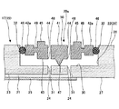
図14は、本実施の形態に係る搬送アームの第1の取付孔に真空吸着パッドが取り付けられている状態を模式的に示す断面図である。   FIG. 14 is a cross-sectional view schematically showing a state where the vacuum suction pad is attached to the first attachment hole of the transfer arm according to the present embodiment.

本実施の形態に係る真空吸着パッド100eが取付けられるピック19e(搬送アーム17e)を有する基板搬送装置16及び基板処理装置1は、第1の実施の形態と同様である。   The substrate transfer apparatus 16 and the substrate processing apparatus 1 having the pick 19e (transfer arm 17e) to which the vacuum suction pad 100e according to the present embodiment is attached are the same as in the first embodiment.

本実施の形態では、ピック19e(搬送アーム17e)には第1の取付孔22eが形成される。第1の取付孔22eは、第1の実施の形態における取付孔22と同様である。ただし、本実施の形態では、図14に示すように、真空吸引路21eと第1の取付孔22eとを連通する取付孔連通路24eは、1つ形成される。従って、第1の取付孔22eの底面30eに取付孔連通路24eが開口する開口部31eは1つ形成される。また、開口部31eは、本発明における第5の開口部に相当する。   In the present embodiment, the first mounting hole 22e is formed in the pick 19e (conveying arm 17e). The first mounting hole 22e is the same as the mounting hole 22 in the first embodiment. However, in the present embodiment, as shown in FIG. 14, one mounting hole communication path 24e that connects the vacuum suction path 21e and the first mounting hole 22e is formed. Accordingly, one opening 31e is formed in the bottom surface 30e of the first mounting hole 22e so that the mounting hole communication path 24e opens. The opening 31e corresponds to the fifth opening in the present invention.

本実施の形態に係る真空吸着パッド100eは、内側パッド20e、外側パッド120eを有する。   The vacuum suction pad 100e according to the present embodiment includes an inner pad 20e and an outer pad 120e.

内側パッド20eは、上面部41e、第1の側周面部42e、第1の下面部43eを有する。   The inner pad 20e has an upper surface portion 41e, a first side peripheral surface portion 42e, and a first lower surface portion 43e.

上面部41eの中心に対して互いに対称な位置に開口部44eが2つ形成されており、開口部44eが3つ以上形成されてもよく、1つのみ形成されてもよく、開口部44eが本発明における第1の開口部に相当し、また、上面部41eから突出し、開口部44eを取り囲むように接触部45eが形成されているのは、第1の実施の形態と同様である。   Two openings 44e are formed at positions symmetrical to each other with respect to the center of the upper surface portion 41e. Three or more openings 44e may be formed, or only one opening 44e may be formed. Similar to the first embodiment, the contact portion 45e corresponds to the first opening portion in the present invention, protrudes from the upper surface portion 41e, and surrounds the opening portion 44e.

第1の側周面部42eには、第1のシール部材32eを装着する第1の装着溝46e(装着部)が形成されている。第1の装着溝46eは、第1の実施の形態における装着溝46と同様である。   A first mounting groove 46e (mounting portion) for mounting the first seal member 32e is formed in the first side peripheral surface portion 42e. The first mounting groove 46e is the same as the mounting groove 46 in the first embodiment.

第1の下面部43eには、外側パッド120eに形成された第2の取付孔122eの底面130eに当接する第1の脚部47eが形成されている。第1の脚部47eは、第1の下面部43eの中心に形成されていてもよく、第1の下面部43eの中心でない位置に形成されていてもよい。また、第1の下面部43eには、開口部44eと連通する開口部48eが形成されている。開口部48eは、開口部44eに対応し、3つ以上形成されていてもよく、1つ形成されていてもよい。開口部44eは、本発明における第2の開口部に相当する。   The first lower surface portion 43e is formed with a first leg portion 47e that comes into contact with the bottom surface 130e of the second mounting hole 122e formed in the outer pad 120e. The first leg portion 47e may be formed at the center of the first lower surface portion 43e, or may be formed at a position other than the center of the first lower surface portion 43e. Further, an opening 48e communicating with the opening 44e is formed in the first lower surface portion 43e. Three or more openings 48e may be formed corresponding to the openings 44e, or one may be formed. The opening 44e corresponds to the second opening in the present invention.

内側パッド20eは、第1の装着溝46eに装着された第1のシール部材32eを介して、第1の側周面部42eが外側パッド120eに形成された第2の取付孔122eの内壁129eに対向するように取付けられている。これにより、第1の下面部43eと第2の取付孔122eの底面130eとで囲まれた空間を、第1のシール部材32eにより気密に保持する。   The inner side pad 20e is connected to the inner wall 129e of the second mounting hole 122e in which the first side peripheral surface portion 42e is formed in the outer side pad 120e through the first seal member 32e mounted in the first mounting groove 46e. It is installed so as to face each other. Thereby, the space surrounded by the first lower surface portion 43e and the bottom surface 130e of the second mounting hole 122e is airtightly held by the first seal member 32e.

外側パッド120eは、第2の取付孔122eが形成され、第2の側周面部142e、第2の下面部143eを有する。   The outer pad 120e has a second attachment hole 122e, and has a second side peripheral surface portion 142e and a second lower surface portion 143e.

第2の取付孔122eは、外側パッド120eのウェハWを保持する保持面(上面)26側に形成され、外側パッド120eを上下に貫通せず、途中まで形成された凹部である。第2の取付孔122eは、内壁129e及び底面130eを有する。第2の取付孔122eの底面130eには、第2の取付孔122eの底面130eから第2の下面部143eにかけて貫通する貫通孔124eが開口し、開口部144eが形成されている。図14に示す例では、貫通孔124e及び開口部144eが1つずつ形成されている。貫通孔124e及び開口部144eは、2つ以上形成されてもよい。開口部144eは、本発明における第3の開口部に相当する。なお、第2の取付孔122eの平面視での形状は、略円形であってもよく、円形以外の方形等の種々の形状であってもよい。   The second mounting hole 122e is a recess formed on the holding surface (upper surface) 26 side for holding the wafer W of the outer pad 120e and formed partway without penetrating the outer pad 120e vertically. The second mounting hole 122e has an inner wall 129e and a bottom surface 130e. A through hole 124e that penetrates from the bottom surface 130e of the second mounting hole 122e to the second lower surface portion 143e is opened on the bottom surface 130e of the second mounting hole 122e, and an opening portion 144e is formed. In the example shown in FIG. 14, one through hole 124e and one opening 144e are formed. Two or more through holes 124e and openings 144e may be formed. The opening 144e corresponds to the third opening in the present invention. The shape of the second mounting hole 122e in plan view may be a substantially circular shape, or may be various shapes such as a square other than a circular shape.

第2の側周面部142eには、第2のシール部材132eを装着する第2の装着溝146eが形成されている。   A second mounting groove 146e for mounting the second seal member 132e is formed in the second side peripheral surface portion 142e.

第2の下面部143eには、ピック19e(搬送アーム17e)に形成された第1の取付孔22eの底面30eに当接する第2の脚部147eが形成されている。第2の脚部147eが、第2の下面部143eの中心に形成されていてもよく、第2の下面部143eの中心でない位置に形成されていてもよい。また、第2の下面部143eには、開口部144eと連通する開口部148eが形成されている。開口部148eは、開口部144eに対応し、2つ以上形成されていてもよい。開口部148eは、本発明における第4の開口部に相当する。   The second lower surface portion 143e is formed with a second leg portion 147e that comes into contact with the bottom surface 30e of the first mounting hole 22e formed in the pick 19e (conveying arm 17e). The second leg 147e may be formed at the center of the second lower surface 143e, or may be formed at a position other than the center of the second lower surface 143e. In addition, an opening 148e communicating with the opening 144e is formed in the second lower surface part 143e. Two or more openings 148e may be formed corresponding to the openings 144e. The opening 148e corresponds to the fourth opening in the present invention.

外側パッド120eは、第2の装着溝146eに装着された第2のシール部材132eを介して、第2の側周面部142eがピック19e(搬送アーム17e)に形成された第1の取付孔22eの内壁29eに対向するように取付けられている。これにより、第2の下面部143eと第1の取付孔22eの底面30eとで囲まれた空間を、第2のシール部材132eにより気密に保持する。   The outer pad 120e has a first mounting hole 22e in which a second side peripheral surface portion 142e is formed in the pick 19e (conveying arm 17e) via a second seal member 132e mounted in the second mounting groove 146e. It is attached to face the inner wall 29e. Thereby, the space surrounded by the second lower surface portion 143e and the bottom surface 30e of the first attachment hole 22e is airtightly held by the second seal member 132e.

以上の結果、ウェハWは、開口部44e、開口部48e、開口部144e、開口部148e、開口部31eを介してピック19e(搬送アーム17e)の真空吸引路21eにより真空吸着される。   As a result, the wafer W is vacuum-sucked by the vacuum suction path 21e of the pick 19e (transfer arm 17e) through the opening 44e, the opening 48e, the opening 144e, the opening 148e, and the opening 31e.

また、第1のシール部材32e及び第2のシール部材132eとして、Oリングを含めた環状の弾性シール部材を用いることができるのは、第1の実施の形態と同様である。   Further, as in the first embodiment, an annular elastic seal member including an O-ring can be used as the first seal member 32e and the second seal member 132e.

本実施の形態に係る真空吸着パッド100eは、内側パッド20e、外側パッド120eよりなる二重構造を有しており、内側パッド20eは、第1のシール部材32e、外側パッド120e、第2のシール部材132eを介して第1の取付孔22eに取付けられる。従って、内側パッド20eは、第1のシール部材32e、第2のシール部材132eの2つのシール部材の弾性変形によって上下方向及び水平方向に移動することができるため、比較的単純な構造で基板吸着パッドをウェハの表面に沿って変位させることができる。
(第4の実施の形態)
次に、図15を参照し、本発明の第4の実施の形態に係る搬送アーム及び真空吸着パッドについて説明する。
The vacuum suction pad 100e according to the present embodiment has a double structure including an inner pad 20e and an outer pad 120e. The inner pad 20e includes a first seal member 32e, an outer pad 120e, and a second seal. It is attached to the first attachment hole 22e via the member 132e. Accordingly, the inner pad 20e can move in the vertical direction and the horizontal direction by elastic deformation of the two sealing members of the first sealing member 32e and the second sealing member 132e. The pad can be displaced along the surface of the wafer.
(Fourth embodiment)
Next, a transport arm and a vacuum suction pad according to the fourth embodiment of the present invention will be described with reference to FIG.

本実施の形態は、ピック19f(搬送アーム17f)に第1の貫通孔22fが形成され、ピック19f(搬送アーム17f)が、内側パッド20fと、内側パッド20fが取り付けられる第2の貫通孔122fが形成された外側パッド120fとを有する点で、第2の実施の形態に係る真空吸着パッド20cと相違する。   In the present embodiment, the first through hole 22f is formed in the pick 19f (conveying arm 17f), and the pick 19f (conveying arm 17f) is connected to the inner pad 20f and the second through hole 122f to which the inner pad 20f is attached. This is different from the vacuum suction pad 20c according to the second embodiment in that it has an outer pad 120f formed with a.

図15は、本実施の形態に係る搬送アームの第1の貫通孔に真空吸着パッドが取り付けられている状態を模式的に示す断面図である。   FIG. 15 is a cross-sectional view schematically showing a state in which a vacuum suction pad is attached to the first through hole of the transfer arm according to the present embodiment.

本実施の形態に係る真空吸着パッド100fが取付けられるピック19f(搬送アーム17f)を有する基板搬送装置16及び基板処理装置1は、第1の実施の形態と同様である。   The substrate transfer apparatus 16 and the substrate processing apparatus 1 having the pick 19f (transfer arm 17f) to which the vacuum suction pad 100f according to the present embodiment is attached are the same as those in the first embodiment.

本実施の形態では、ピック19f(搬送アーム17f)には第1の貫通孔22fが形成される。第1の貫通孔22fは、第2の実施の形態における貫通孔22cと同様である。また、第1の貫通孔22fの内壁29fに形成された、貫通孔連通路24fが開口する開口部31fは、本発明における第5の開口部に相当する。また、貫通孔連通路24fが水平孔33、垂直孔37よりなりL字形状を有すること、加工孔34を有することも、第2の実施の形態と同様である。   In the present embodiment, a first through hole 22f is formed in the pick 19f (conveying arm 17f). The first through hole 22f is the same as the through hole 22c in the second embodiment. The opening 31f formed in the inner wall 29f of the first through hole 22f and through which the through hole communication path 24f opens is equivalent to the fifth opening in the present invention. Further, the through-hole communication path 24f is formed of a horizontal hole 33 and a vertical hole 37, has an L shape, and has a processed hole 34, as in the second embodiment.

本実施の形態に係る真空吸着パッド100fは、内側パッド20f、外側パッド120fを有する。   The vacuum suction pad 100f according to the present embodiment includes an inner pad 20f and an outer pad 120f.

内側パッド20fは、上面部41f、第1の側周面部42f、第1の下面部43fを有する。   The inner pad 20f has an upper surface portion 41f, a first side peripheral surface portion 42f, and a first lower surface portion 43f.

上面部41fに、上面部41fの中心に開口部44fが1つ形成されており、開口部44fが2つ以上形成されてもよく、開口部44fが本発明における第1の開口部に相当し、また、上面部41fから突出し、開口部44fを取り囲むように接触部45fが形成されているのは、第1の実施の形態と同様である。   One opening 44f may be formed in the upper surface 41f at the center of the upper surface 41f, and two or more openings 44f may be formed. The opening 44f corresponds to the first opening in the present invention. Also, the contact portion 45f is formed so as to protrude from the upper surface portion 41f and surround the opening portion 44f, as in the first embodiment.

第1の側周面部42fには、第1のシール部材32fを装着する第1の装着溝46f(装着部)が2つ形成されている。   Two first mounting grooves 46f (mounting portions) for mounting the first seal member 32f are formed on the first side peripheral surface portion 42f.

また、第1の側周面部42fには、開口部44fと連通する開口部48fが1つ形成されている。開口部48fは、開口部44fに対応し、2つ以上形成されてもよい。開口部48fは、本発明における第2の開口部に相当する。   In addition, one opening 48f communicating with the opening 44f is formed in the first side peripheral surface portion 42f. Two or more openings 48f may be formed corresponding to the openings 44f. The opening 48f corresponds to the second opening in the present invention.

第1の下面部43fには、第1の突起部51fが形成されている。第1の突起部51fは、図15に示すように、ピック19f(搬送アーム17f)のウェハWを保持する保持面(上面)26と反対面(下面)27に形成され、外側パッド120fに形成される第2の貫通孔122fを形成する開口部138fの切欠部139fに係止される。第1の突起部51fは、第2の貫通孔122fの断面形状よりも大きな断面形状を有している。   A first protrusion 51f is formed on the first lower surface portion 43f. As shown in FIG. 15, the first protruding portion 51f is formed on the holding surface (upper surface) 26 opposite to the holding surface (upper surface) 26 of the pick 19f (transfer arm 17f) (lower surface) 27 and formed on the outer pad 120f. The second through hole 122f to be formed is engaged with the notch 139f of the opening 138f. The first protrusion 51f has a larger cross-sectional shape than the cross-sectional shape of the second through hole 122f.

内側パッド20fは、第1の装着溝46fに装着された第1のシール部材32fを介して、第1の側周面部42fが外側パッド120fに形成された第2の貫通孔122fの内壁129fに対向するように取付けられている。これにより、第1の側周面部42fと第2の貫通孔122fの内壁129fとで挟まれた空間を、第1のシール部材32fにより気密に保持する。   The inner pad 20f is connected to the inner wall 129f of the second through-hole 122f in which the first side peripheral surface portion 42f is formed in the outer pad 120f via the first seal member 32f mounted in the first mounting groove 46f. It is installed so as to face each other. Thereby, the space sandwiched between the first side peripheral surface portion 42f and the inner wall 129f of the second through hole 122f is airtightly held by the first seal member 32f.

外側パッド120fは、中心に第2の貫通孔122fが形成され、第2の側周面部142f、第2の下面部143fを有する。   The outer pad 120f has a second through-hole 122f at the center, and has a second side peripheral surface portion 142f and a second lower surface portion 143f.

第2の貫通孔122fは、外側パッド120fのウェハWを保持する側の保持面(上面)126から反対面(下面)127まで貫通するように形成された孔である。第2の貫通孔122fの内壁129fには、第2の貫通孔122fと第1の貫通孔22fとを連通する貫通孔124fが開口し、開口部144fが形成されている。図15に示す例では、貫通孔124f及び開口部144fが1つずつ形成されている。貫通孔124f及び開口部144fは、2つ以上形成されてもよい。また、開口部144fは、本発明における第3の開口部に相当する。なお、第2の貫通孔122fの平面視での形状は、略円形であってもよく、円形以外の方形等の種々の形状であってもよい。   The second through hole 122f is a hole formed so as to penetrate from the holding surface (upper surface) 126 on the side of holding the wafer W of the outer pad 120f to the opposite surface (lower surface) 127. On the inner wall 129f of the second through hole 122f, a through hole 124f that connects the second through hole 122f and the first through hole 22f opens, and an opening 144f is formed. In the example shown in FIG. 15, one through hole 124f and one opening 144f are formed. Two or more through holes 124f and openings 144f may be formed. The opening 144f corresponds to the third opening in the present invention. Note that the shape of the second through-hole 122f in plan view may be substantially circular, or may be various shapes such as a square other than a circle.

第2の側周面部142fには、第2のシール部材132fを装着する第2の装着溝146fが2つ形成されている。また、第2の側周面部142fには、開口部144fと連通する開口部148fが1つ形成されている。開口部148fは、開口部144fに対応し、2つ以上形成されてもよい。開口部148fは、本発明における第4の開口部に相当する。   Two second mounting grooves 146f for mounting the second seal member 132f are formed in the second side peripheral surface portion 142f. In addition, one opening 148f that communicates with the opening 144f is formed in the second side peripheral surface 142f. Two or more openings 148f may be formed corresponding to the openings 144f. The opening 148f corresponds to the fourth opening in the present invention.

第2の下面部143fには、第2の突起部151fが形成されている。第2の突起部151fは、図15に示すように、外側パッド120fのウェハWを保持する側の保持面(上面)126と反対面(下面)127に形成され、ピック19f(搬送アーム17f)に形成される第1の貫通孔22fを形成する開口部38fの切欠部39fに係止される。第2の突起部151fは、第1の貫通孔22fの断面形状よりも大きな断面形状を有している。   A second projecting portion 151f is formed on the second lower surface portion 143f. As shown in FIG. 15, the second protrusion 151f is formed on the holding surface (upper surface) 126 opposite to the holding surface (upper surface) 126 of the outer pad 120f on the surface (lower surface) 127, and the pick 19f (transfer arm 17f). The first through hole 22f formed in the opening 38f is engaged with a notch 39f. The second protrusion 151f has a larger cross-sectional shape than the cross-sectional shape of the first through hole 22f.

外側パッド120fは、第2の装着溝146fに装着された第2のシール部材132fを介して、第2の側周面部142fがピック19f(搬送アーム17f)に形成された第1の貫通孔22fの内壁29fに対向するように取付けられている。これにより、第2の側周面部142fと第1の貫通孔22fの内壁29fとで挟まれた空間を、第2のシール部材132fにより気密に保持する。   The outer pad 120f has a first through hole 22f in which a second side peripheral surface portion 142f is formed in the pick 19f (conveying arm 17f) via a second seal member 132f mounted in the second mounting groove 146f. It is attached to face the inner wall 29f. Thereby, the space sandwiched between the second side peripheral surface portion 142f and the inner wall 29f of the first through hole 22f is airtightly held by the second seal member 132f.

以上の結果、ウェハWは、開口部44f、開口部48f、開口部144f、開口部148f、開口部31fを介してピック19f(搬送アーム17f)の真空吸引路21fにより真空吸着される。   As a result, the wafer W is vacuum-sucked by the vacuum suction path 21f of the pick 19f (transfer arm 17f) through the opening 44f, the opening 48f, the opening 144f, the opening 148f, and the opening 31f.

また、第1のシール部材32f及び第2のシール部材132fとして、Oリングを含めた環状の弾性シール部材を用いることができるのは、第1の実施の形態と同様である。   As in the first embodiment, an annular elastic seal member including an O-ring can be used as the first seal member 32f and the second seal member 132f.

本実施の形態に係る真空吸着パッド100fも、第3の実施の形態と同様に、内側パッド20f、外側パッド120fよりなる二重構造を有しており、内側パッド20fは、第1のシール部材32f、外側パッド120f、第2のシール部材132fを介して第1の取付孔22fに取付けられる。従って、比較的単純な構造で基板吸着パッドを基板表面に沿って変位させることができる。   Similarly to the third embodiment, the vacuum suction pad 100f according to the present embodiment has a double structure including an inner pad 20f and an outer pad 120f, and the inner pad 20f is a first seal member. 32f, the outer pad 120f, and the second seal member 132f are attached to the first attachment hole 22f. Therefore, the substrate suction pad can be displaced along the substrate surface with a relatively simple structure.

また、第2の実施の形態と同様に、保持面(上面)26側と反対面(下面)27側の双方から大気圧力が作用するため、これらがバランスして、真空吸着の際に真空吸着パッドが変位しにくい。
(第5の実施の形態)
次に、図16を参照し、本発明の第5の実施の形態に係る真空吸着パッドについて説明する。
Further, as in the second embodiment, since atmospheric pressure acts from both the holding surface (upper surface) 26 side and the opposite surface (lower surface) 27 side, they are balanced and vacuum suction is performed during vacuum suction. The pad is difficult to displace.
(Fifth embodiment)
Next, a vacuum suction pad according to a fifth embodiment of the present invention will be described with reference to FIG.

本実施の形態は、第3の実施の形態に係る内側パッドを、取付孔が形成された外側パッドを介して、搬送アームの貫通孔に取り付けるものである。   In this embodiment, the inner pad according to the third embodiment is attached to the through-hole of the transfer arm via the outer pad in which the attachment hole is formed.

図16は、本実施の形態に係る搬送アームの貫通孔に真空吸着パッドが取り付けられている状態を模式的に示す断面図である。   FIG. 16 is a cross-sectional view schematically showing a state in which the vacuum suction pad is attached to the through hole of the transfer arm according to the present embodiment.

本実施の形態では、真空吸着パッド100gが取付けられるピック19g(搬送アーム17g)を有する基板搬送装置16及び基板処理装置1は、第1の実施の形態と同様である。また、真空吸着パッド100gが取付けられるピック19g(搬送アーム17g)は、第4の実施の形態と同様である。また、真空吸着パッド100gは、内側パッド20g、外側パッド120gを有し、内側パッド20gは、第3の実施の形態に係る内側パッド20eと同様である。   In the present embodiment, the substrate transfer apparatus 16 and the substrate processing apparatus 1 having the pick 19g (transfer arm 17g) to which the vacuum suction pad 100g is attached are the same as those in the first embodiment. The pick 19g (conveying arm 17g) to which the vacuum suction pad 100g is attached is the same as that in the fourth embodiment. The vacuum suction pad 100g has an inner pad 20g and an outer pad 120g, and the inner pad 20g is the same as the inner pad 20e according to the third embodiment.

外側パッド120gは、中心に第2の取付孔122gが形成され、第2の側周面部142g、第2の下面部143gを有する。   The outer pad 120g has a second attachment hole 122g at the center, and has a second side peripheral surface portion 142g and a second lower surface portion 143g.

第2の取付孔122gは、外側パッド120gのウェハWを保持する側の保持面(上面)126に形成され、外側パッド120gの保持面(上面)126から反対面(下面)127まで貫通せず、保持面(上面)126から反対面(下面)127までの途中まで形成された凹部である。第2の取付孔122gの内壁129gには、第2の取付孔122gから第2の側周面部142gにかけて貫通する貫通孔124gが開口し、開口部144gが形成されている。図16に示す例では、貫通孔124g及び開口部144gが1つずつ形成されている。貫通孔124g及び開口部144gは、2つ以上形成されてもよい。開口部144gは、本発明における第3の開口部に相当する。   The second mounting hole 122g is formed in the holding surface (upper surface) 126 on the side of the outer pad 120g that holds the wafer W, and does not penetrate from the holding surface (upper surface) 126 of the outer pad 120g to the opposite surface (lower surface) 127. , A recess formed partway from the holding surface (upper surface) 126 to the opposite surface (lower surface) 127. On the inner wall 129g of the second mounting hole 122g, a through hole 124g penetrating from the second mounting hole 122g to the second side peripheral surface portion 142g is opened to form an opening 144g. In the example shown in FIG. 16, one through hole 124g and one opening 144g are formed. Two or more through holes 124g and openings 144g may be formed. The opening 144g corresponds to the third opening in the present invention.

第2の側周面部142gには、第2のシール部材132gを装着する第2の装着溝146g(装着部)が2つ形成されている。第2の装着溝146gは、第4の実施の形態における第2の装着溝146fと同様である。   Two second mounting grooves 146g (mounting portions) for mounting the second seal member 132g are formed on the second side peripheral surface portion 142g. The second mounting groove 146g is the same as the second mounting groove 146f in the fourth embodiment.

また、第2の側周面部142gには、開口部144gと連通する開口部148gが1つ形成されている。開口部148gは、開口部144gに対応し、2つ以上形成されてもよい。開口部148gは、本発明における第4の開口部に相当する。   Further, one opening 148g communicating with the opening 144g is formed in the second side peripheral surface 142g. Two or more openings 148g may be formed corresponding to the openings 144g. The opening 148g corresponds to the fourth opening in the present invention.

また、第2の下面部143gには、第4の実施の形態と同様に、第2の突起部151gが形成されている。   Further, a second protrusion 151g is formed on the second lower surface portion 143g, as in the fourth embodiment.

本実施の形態に係る真空吸着パッド100gも、第3の実施の形態及び第4の実施の形態と同様に、内側パッド20g、外側パッド120gよりなる二重構造を有しており、内側パッド20gは、第1のシール部材32g、外側パッド120g、第2のシール部材132gを介して第1の取付孔22gに取付けられる。従って、比較的単純な構造で基板吸着パッドをウェハの表面に沿って変位させることができる。   Similarly to the third embodiment and the fourth embodiment, the vacuum suction pad 100g according to the present embodiment also has a double structure including the inner pad 20g and the outer pad 120g, and the inner pad 20g. Is attached to the first attachment hole 22g via the first seal member 32g, the outer pad 120g, and the second seal member 132g. Therefore, the substrate suction pad can be displaced along the surface of the wafer with a relatively simple structure.

以上、本発明の好ましい実施の形態について記述したが、本発明はかかる特定の実施の形態に限定されるものではなく、特許請求の範囲内に記載された本発明の要旨の範囲内において、種々の変形・変更が可能である。   The preferred embodiments of the present invention have been described above, but the present invention is not limited to such specific embodiments, and various modifications can be made within the scope of the gist of the present invention described in the claims. Can be modified or changed.

また、本発明に係る基板搬送装置を備えた基板処理装置は、基板処理としてエッチング処理に限定されるものではなく、成膜処理、塗布処理、現像処理、洗浄処理を含めた広範な種類の基板処理を行う基板処理装置に適用可能なものである。   In addition, the substrate processing apparatus provided with the substrate transfer apparatus according to the present invention is not limited to the etching process as the substrate process, but a wide variety of substrates including a film forming process, a coating process, a developing process, and a cleaning process. The present invention is applicable to a substrate processing apparatus that performs processing.

なお、本発明に係る各実施形態においては、下方からウェハを水平に支持する搬送アームに取り付けられる真空吸着パッドについて述べてきたが、本発明は係る向きに限定されるものではない。すなわち、上方からウェハを水平に真空吸着する搬送アームに取り付けられる真空吸着パッドであっても良いし、水平ではなく、垂直や斜め方向にウェハを真空吸着する搬送アームに取り付けられる真空吸着パッドであっても良い。   In each of the embodiments according to the present invention, the vacuum suction pad attached to the transfer arm that horizontally supports the wafer from below has been described, but the present invention is not limited to such a direction. That is, it may be a vacuum suction pad attached to a transfer arm that vacuum-sucks a wafer horizontally from above, or a vacuum suction pad attached to a transfer arm that vacuum-sucks a wafer vertically or obliquely rather than horizontally. May be.

1 基板処理装置
16 基板搬送装置
17 搬送アーム
19 ピック
20 真空吸着パッド
21 真空吸引路
22 取付孔
29 内壁
30 底面
32 シール部材
41 上面部
42 側周面部
43 下面部
45 接触部
46 装着溝
47 脚部
49 薄肉部
50 本体部
51 突起部
DESCRIPTION OF SYMBOLS 1 Substrate processing apparatus 16 Substrate transfer apparatus 17 Transfer arm 19 Pick 20 Vacuum suction pad 21 Vacuum suction path 22 Mounting hole 29 Inner wall 30 Bottom surface 32 Seal member 41 Upper surface part 42 Side peripheral surface part 43 Lower surface part 45 Contact part 46 Mounting groove 47 Leg part 49 Thin-walled part 50 Main-body part 51 Projection part

Claims (9)

基板搬送装置の搬送アームに形成された第1の取付孔に取り付けられ、前記搬送アームの真空吸引路に連結されて、基板を該搬送アームに真空吸着する真空吸着パッドであって、
第1の開口部を備える内側パッドと、前記内側パッドが取り付けられる第2の取付孔が形成された外側パッドとを有し、
前記内側パッドは、前記第1の開口部が形成された上面部と、第1のシール部材を配置する第1の装着部が形成された第1の側周面部と、前記第2の取付孔の底面に当接する第1の脚部が形成された第1の下面部とを備え、
前記外側パッドは、第2のシール部材を配置する第2の装着部が形成された第2の側周面部と、前記第1の取付孔の底面に当接する第2の脚部が形成された第2の下面部とを備え、
前記第1の側周面部は、前記第1の装着部に配置した前記第1のシール部材を介して、前記第2の取付孔に取り付けられ、
前記第2の側周面部は、前記第2の装着部に配置した前記第2のシール部材を介して、前記第1の取付孔に取り付けられる、
ことを特徴とする真空吸着パッド。
A vacuum suction pad attached to a first mounting hole formed in a transfer arm of a substrate transfer device, connected to a vacuum suction path of the transfer arm, and vacuum-adsorbing a substrate to the transfer arm;
An inner pad provided with a first opening, and an outer pad formed with a second attachment hole to which the inner pad is attached;
The inner pad includes an upper surface portion on which the first opening is formed, a first side peripheral surface portion on which a first mounting portion for disposing a first seal member is formed, and the second mounting hole. A first lower surface portion formed with a first leg portion that contacts the bottom surface of
The outer pad has a second side peripheral surface portion on which a second mounting portion for disposing a second seal member is formed, and a second leg portion that contacts the bottom surface of the first mounting hole. A second lower surface portion,
The first side peripheral surface portion is attached to the second attachment hole via the first seal member disposed in the first mounting portion,
The second side peripheral surface portion is attached to the first attachment hole via the second seal member disposed in the second mounting portion.
A vacuum suction pad characterized by that.
前記第1のシール部材は、前記第1の下面部と前記第2の取付孔の底面とで挟まれた空間の気密を確保し、
前記第2のシール部材は、前記第2の下面部と前記第1の取付孔の底面とで挟まれた空間の気密を確保する、
ことを特徴とする請求項1に記載の真空吸着パッド。
The first seal member ensures airtightness of a space sandwiched between the first lower surface portion and the bottom surface of the second mounting hole,
The second seal member ensures airtightness of a space sandwiched between the second lower surface portion and the bottom surface of the first attachment hole.
The vacuum suction pad according to claim 1 .
前記第1の下面部は、前記第1の開口部と連通する第2の開口部を有し、
前記第2の取付孔は、該第2の取付孔の底面に第3の開口部を有し、
前記第2の下面部は、前記第3の開口部と連通する第4の開口部を有し、
前記第1の取付孔は、該第1の取付孔の底面に第5の開口部を有し、
前記内側パッドに当接した前記基板は、該内側パッドの前記上面部の前記第1の開口部と連通する前記第2の開口部、前記第3の開口部、前記第4の開口部及び前記第5の開口部を介して、該上面部に真空吸着される、
ことを特徴とする請求項1又は請求項2に記載の真空吸着パッド。
The first lower surface portion has a second opening communicating with the first opening,
The second mounting hole has a third opening on the bottom surface of the second mounting hole,
The second lower surface portion has a fourth opening communicating with the third opening,
The first mounting hole has a fifth opening on the bottom surface of the first mounting hole;
The substrate in contact with the inner pad includes the second opening, the third opening, the fourth opening, and the communication between the first opening on the upper surface of the inner pad. The upper surface is vacuum-adsorbed through the fifth opening,
The vacuum suction pad according to claim 1 or 2 , characterized by the above.
前記上面部は、複数の前記第1の開口部を有する、ことを特徴とする請求項1乃至請求項3のいずれか一項に記載の真空吸着パッド。 Said upper surface portion, the vacuum suction pad according to any one of claims 1 to 3 having a plurality of said first opening, and wherein the. 前記第1のシール部材及び/又は前記第2のシール部材は、弾性変形するOリングである、ことを特徴とする請求項1乃至請求項4のいずれか一項に記載の真空吸着パッド。 It said first sealing member and / or the second seal member is an O-ring is elastically deformed, the vacuum suction pad according to any one of claims 1 to 4, characterized in that. 前記第1の装着部及び/又は前記第2の装着部は、装着溝を有し、該装着溝に前記第1のシール部材又は前記第2のシール部材を装着される、ことを特徴とする請求項1乃至請求項5のいずれか一項に記載の真空吸着パッド。 The first mounting portion and / or the second mounting portion has a mounting groove, and the first sealing member or the second sealing member is mounted in the mounting groove. vacuum suction pad according to any one of claims 1 to 5. 請求項1乃至請求項6のいずれか一項に記載の真空吸着パッドを有する搬送アーム。 The conveyance arm which has a vacuum suction pad as described in any one of Claims 1 thru | or 6 . 前記取付孔は、該取付孔の底面に第3の開口部を有し、
前記真空吸着パッドに当接した前記基板は、前記第2の開口部及び前記第3の開口部を介して、真空吸着される、
ことを特徴とする請求項7に記載の搬送アーム。
The mounting hole has a third opening on the bottom surface of the mounting hole;
The substrate in contact with the vacuum suction pad is vacuum-sucked through the second opening and the third opening.
The transfer arm according to claim 7 .
請求項7又は請求項8に記載の搬送アームを備えた基板搬送装置。
A substrate transfer apparatus comprising the transfer arm according to claim 7 .
JP2009173195A 2009-07-24 2009-07-24 Vacuum suction pad, transfer arm and substrate transfer device Expired - Fee Related JP5379589B2 (en)

Priority Applications (1)

Application Number Priority Date Filing Date Title
JP2009173195A JP5379589B2 (en) 2009-07-24 2009-07-24 Vacuum suction pad, transfer arm and substrate transfer device

Applications Claiming Priority (1)

Application Number Priority Date Filing Date Title
JP2009173195A JP5379589B2 (en) 2009-07-24 2009-07-24 Vacuum suction pad, transfer arm and substrate transfer device

Publications (3)

Publication Number Publication Date
JP2011029388A JP2011029388A (en) 2011-02-10
JP2011029388A5 JP2011029388A5 (en) 2012-11-01
JP5379589B2 true JP5379589B2 (en) 2013-12-25

Family

ID=43637800

Family Applications (1)

Application Number Title Priority Date Filing Date
JP2009173195A Expired - Fee Related JP5379589B2 (en) 2009-07-24 2009-07-24 Vacuum suction pad, transfer arm and substrate transfer device

Country Status (1)

Country Link
JP (1) JP5379589B2 (en)

Cited By (1)

* Cited by examiner, † Cited by third party
Publication number Priority date Publication date Assignee Title
KR20200001966A (en) 2018-06-28 2020-01-07 히라따기꼬오 가부시키가이샤 Alignment device, semiconductor wafer processing device, and alignment method

Families Citing this family (6)

* Cited by examiner, † Cited by third party
Publication number Priority date Publication date Assignee Title
JP5345167B2 (en) 2011-03-18 2013-11-20 東京エレクトロン株式会社 Substrate holding device
JP6224437B2 (en) 2013-11-26 2017-11-01 東京エレクトロン株式会社 Substrate transfer device
JP6032234B2 (en) 2014-03-19 2016-11-24 信越半導体株式会社 Work holding device
JP6298099B2 (en) 2016-05-18 2018-03-20 キヤノントッキ株式会社 Substrate transfer device
US11315823B2 (en) * 2019-12-27 2022-04-26 Kawasaki Jukogyo Kabushiki Kaisha Substrate suction-holding structure and substrate transfer robot
KR20230168274A (en) 2022-06-06 2023-12-13 도쿄엘렉트론가부시키가이샤 Mounting pad, mounting mechanism, and substrate transfer mechanism

Family Cites Families (7)

* Cited by examiner, † Cited by third party
Publication number Priority date Publication date Assignee Title
JPH08143147A (en) * 1994-11-18 1996-06-04 Metsukusu:Kk Sucking device for sheet-form work
JP3282787B2 (en) * 1996-07-29 2002-05-20 東京エレクトロン株式会社 Wafer transfer mechanism
JP3782523B2 (en) * 1996-09-12 2006-06-07 オリンパス株式会社 Substrate adsorption member and apparatus
JP3408780B2 (en) * 2000-06-05 2003-05-19 株式会社しなのエレクトロニクス Vacuum gripper and IC test handler
JP3917528B2 (en) * 2003-01-07 2007-05-23 エスペック株式会社 Suction pad
JP2006073946A (en) * 2004-09-06 2006-03-16 Fuji Mach Mfg Co Ltd Glass substrate feeder
JP4790395B2 (en) * 2005-12-02 2011-10-12 オリンパス株式会社 Substrate adsorption mechanism and substrate inspection device

Cited By (2)

* Cited by examiner, † Cited by third party
Publication number Priority date Publication date Assignee Title
KR20200001966A (en) 2018-06-28 2020-01-07 히라따기꼬오 가부시키가이샤 Alignment device, semiconductor wafer processing device, and alignment method
US11232962B2 (en) 2018-06-28 2022-01-25 Hirata Corporation Alignment device, semiconductor wafer processing device, and alignment method

Also Published As

Publication number Publication date
JP2011029388A (en) 2011-02-10

Similar Documents

Publication Publication Date Title
JP5379589B2 (en) Vacuum suction pad, transfer arm and substrate transfer device
US8171964B2 (en) Apparatus and method for opening/closing lid of closed container, gas replacement apparatus using same, and load port apparatus
TWI412101B (en) Substrate holder, substrate conveyance apparatus, and substrate processing apparatus
JP7109927B2 (en) end effector
JP2016525281A (en) Processing equipment including on-the-fly substrate centering
JP2002324831A (en) Vacuum suction table
CN109755169A (en) Chip carries fork, system for manufacturing semiconductor device and chip transportation method
JP2009117567A (en) Vacuum chuck
KR100337278B1 (en) Container and method for sealing the container
TW201611154A (en) Wafer loading and unloading
KR20210059693A (en) Load port apparatus and method of driving the same
JP5016523B2 (en) Vacuum chuck
KR20140120822A (en) Chuck table
JP7364692B2 (en) Substrate suction holding structure and substrate transfer robot
JP7250525B2 (en) Wafer transfer tray
JPH0243638Y2 (en)
JP2000195927A (en) Vacuum chuck device
JP5749002B2 (en) Load lock device and vacuum processing device
JP2010027809A (en) Conveying device provided with opening/closing mechanism of container for conveying workpiece
TWI662643B (en) Method for manufacturing photomask, plasma process device, and frame
JP2004349619A (en) Interface seal
JP2022065559A (en) Load lock chamber, substrate processing device, and substrate conveyance method
JPH09225768A (en) Board holding device
JP4776560B2 (en) Vacuum processing equipment
KR20020035737A (en) Wafer Carrier, Substrate Processing Device, Substrate Processing System, Substrate Processing Method and Semiconductor Device

Legal Events

Date Code Title Description
A621 Written request for application examination

Free format text: JAPANESE INTERMEDIATE CODE: A621

Effective date: 20120626

A521 Written amendment

Free format text: JAPANESE INTERMEDIATE CODE: A523

Effective date: 20120912

A131 Notification of reasons for refusal

Free format text: JAPANESE INTERMEDIATE CODE: A131

Effective date: 20130611

A977 Report on retrieval

Free format text: JAPANESE INTERMEDIATE CODE: A971007

Effective date: 20130613

A521 Written amendment

Free format text: JAPANESE INTERMEDIATE CODE: A523

Effective date: 20130724

TRDD Decision of grant or rejection written
A01 Written decision to grant a patent or to grant a registration (utility model)

Free format text: JAPANESE INTERMEDIATE CODE: A01

Effective date: 20130910

A61 First payment of annual fees (during grant procedure)

Free format text: JAPANESE INTERMEDIATE CODE: A61

Effective date: 20130927

R150 Certificate of patent or registration of utility model

Ref document number: 5379589

Country of ref document: JP

Free format text: JAPANESE INTERMEDIATE CODE: R150

Free format text: JAPANESE INTERMEDIATE CODE: R150

R250 Receipt of annual fees

Free format text: JAPANESE INTERMEDIATE CODE: R250

LAPS Cancellation because of no payment of annual fees