JP5377095B2 - Fitting structure and connecting pipe - Google Patents
Fitting structure and connecting pipe Download PDFInfo
- Publication number
- JP5377095B2 JP5377095B2 JP2009138737A JP2009138737A JP5377095B2 JP 5377095 B2 JP5377095 B2 JP 5377095B2 JP 2009138737 A JP2009138737 A JP 2009138737A JP 2009138737 A JP2009138737 A JP 2009138737A JP 5377095 B2 JP5377095 B2 JP 5377095B2
- Authority
- JP
- Japan
- Prior art keywords
- valve
- pipe
- receiving port
- cut
- connection
- Prior art date
- Legal status (The legal status is an assumption and is not a legal conclusion. Google has not performed a legal analysis and makes no representation as to the accuracy of the status listed.)
- Active
Links
Images


Abstract
Description
本発明は、施工現場で所定寸法に切断加工して製作された切断端部を有する切管と、他の管の端部に形成された受口とを、接続管を介して接続した管継手構造、および、上記接続管に関する。 The present invention relates to a pipe joint in which a cut pipe having a cut end manufactured by cutting to a predetermined size at a construction site and a receiving port formed at the end of another pipe are connected via a connecting pipe. The present invention relates to the structure and the connecting pipe.
従来、施工現場において、規定寸法(規定長さ)の直管状の管を、実測された配管寸法に基づいて切断して管長を調整し、切断された切管を他の管に接続する場合がある。図11は、上記のような切管81と他の管82とを接続する管継手構造83を示しており、切管81と他の管82とは接続管84を介して接続されている。切管81は、直管状の規格管(例えばJIS等で規定された遠心鋳造により製作された鋳鉄管)を、施工現場において、実際に使用する所定の配管寸法(長さ)に切断加工して製作されており、直管状の切断端部85を有している。
Conventionally, in a construction site, there is a case where a straight pipe having a specified dimension (specified length) is cut based on an actually measured pipe dimension to adjust the pipe length, and the cut cut pipe is connected to another pipe. is there. FIG. 11 shows a
他の管82は、一端部に挿口(図示省略)を有するとともに、他端部に受口86を有する直管状の規格管(鋳鉄管)である。受口86の内周面には、嵌め込み溝87と、嵌め込み溝87よりも受口奥側に位置するロックリング収容溝88とがそれぞれ全周にわたり形成されている。ロックリング収容溝88には、ロックリング89と保持リング90とが収容されている。また、嵌め込み溝87には、ゴム等の弾性材で製作された円環状のシール材91が嵌め込まれている。
The
接続管84は、鋳鉄管であり、一端部に接続管挿口93を有するとともに、他端部に接続管受口94を有している。接続管挿口93は受口86に挿入されており、接続管挿口93の先端部の外周には、ロックリング89に受口奥側から係合可能な抜止突部95が形成されている。
The connecting
尚、シール材91は受口86の内周面と接続管挿口93の外周面との間に挟まれて管径方向において圧縮され、これにより、受口86の内周面と接続管挿口93の外周面との間がシール材91でシールされる。
The sealing
接続管84の接続管受口94には、切管81の切断端部85が切管挿口85として挿入されている。また、接続管受口94には、切管挿口85と接続管受口94との離脱を防止する離脱防止手段96が設けられている。離脱防止手段96は、切管挿口85の外周面に管径方向から食込み移動可能な抜止部材97と、切管挿口85と接続管受口94とが相対的に離脱方向へ移動しようとした際、抜止部材97を管径方向内方側へ食込み移動させる食込み手段98とを有している。食込み手段98は、接続管受口94に設けられ且つ抜止部材97を管径方向内方側へ押圧する押圧ボルト99等を有している。
The
図11〜図13に示すように、接続管受口94の内周には、接続管受口94と切管挿口85との間を全周にわたりシールするゴム製で環状のシール材100が配置されている。シール材100はヒール部101とバルブ部102とを備えている。バルブ部102は、接続管受口94の奥側ほど内径が小さく形成され、その断面形状が管中心に向けて斜め方向へ舌状に突出する略長円形に形成されている。
As shown in FIGS. 11 to 13, an
また、接続管受口94の内周には、シール材配置凹部103が全周にわたり形成され、シール材配置凹部103の底面には、係止溝104が全周にわたり形成されている。シール材100のヒール部101は係止溝104に嵌入されて係合し、バルブ部102が切管挿口85の外周面とシール材配置凹部103の底面との間に挟まれて管径方向において圧縮される。
Further, a sealing material arrangement recess 103 is formed on the entire inner periphery of the connection
以下、上記構成における作用を説明する。
先ず、接続管受口94の係止溝104にシール材100のヒール部101を嵌入し、さらに、接続管受口94に抜止部材97と押圧ボルト99とを組み付け、切管挿口85を接続管受口94に管軸心方向から挿入する。
Hereinafter, the operation of the above configuration will be described.
First, the
切管挿口85がシール材100の内周を通過する際、図12に示すように、バルブ部102の内周部が仮想線で示す状態から実線で示すように管径方向外方に撓むように変形(拡径)し、バルブ部102が切管挿口85の外周面とシール材配置凹部103の底面との間に挟まれて管径方向において圧縮され、これにより、接続管受口94と切管挿口85との間が全周にわたりシールされる。
When the cut tube insertion opening 85 passes through the inner periphery of the
その後、押圧ボルト99を締め付けて、抜止部材97を切管挿口85の外周面に対して食込み移動させる。
また、図11に示すように、他の管82の受口86のロックリング収容溝88にロックリング89と保持リング90とを収容し、嵌め込み溝87にシール材91を嵌め込み、接続管挿口93を受口86に管軸心方向から挿入する。これにより、接続管挿口93の抜止突部95がロックリング89の内周を受口86の開口側(手前側)から奥側へ通過するとともに、シール材91が受口86の内周面と接続管挿口93の外周面との間に挟まれて管径方向において圧縮され、これにより、接続管挿口93と受口86との間が全周にわたりシールされる。
Thereafter, the
Further, as shown in FIG. 11, the
地震等の地盤変動によって管継手構造83に離脱力(抜け出し力)が作用して、切管81と接続管84とが相対的に離脱移動しようとした際、抜止部材97が管径方向内方に食込み移動され、切管挿口85と接続管受口94との接続が強力に維持される。
When the detachment force (extraction force) acts on the
また、上記離脱力が作用して、接続管84と他の管82とが相対的に離脱移動しようとした際、抜止突部95がロックリング89に受口奥側から係合することにより、接続管挿口93と受口86との相対的な離脱移動が強力に阻止される。
Further, when the detachment force acts and the
尚、上記のように接続管84を介して切管81と他の管82とを接続する管継手構造83については、例えば下記特許文献1に記載されている。
In addition, the
しかしながら上記の従来形式では、図12に示すように、切管挿口85を接続管受口94に挿入する時、シール材100のバルブ部102の内周部を仮想線で示す状態から実線で示すように管径方向外方に撓むように変形させるために要する力を低減させることは困難であった。このため、切管挿口85を接続管受口94に挿入する際に、大きな挿入力(接合力)を作用させる必要があるといった問題があった。
However, in the above-described conventional format, as shown in FIG. 12, when the cut
本発明は、切管挿口を接続管受口に挿入する際に要する挿入力を低減することが可能な管継手構造および接続管を提供することを目的とする。 An object of this invention is to provide the pipe joint structure and connection pipe which can reduce the insertion force required when inserting a cut pipe insertion opening in a connection pipe receptacle.
上記目的を達成するために、本第1発明は、施工現場で所定寸法に切断加工して製作された切断端部を有する切管と、他の管の端部に形成された受口とを、接続管を介して接続した管継手構造であって、
接続管は一端に接続管受口を有するとともに他端に接続管挿口を有し、
切管の切断端部が切管挿口として接続管の接続管受口に挿入され、
接続管の接続管挿口が他の管の受口に挿入され、
接続管挿口には、他の管の受口内周に設けられた係止部材に受口奥側から係合可能な抜止突部が設けられ、
切管挿口と接続管受口との離脱を防止する離脱防止手段が備えられ、
切管挿口と接続管受口との間は弾性材からなる環状のシール材によって全周にわたりシールされ、
シール材は、接続管受口の内周面に形成された嵌め込み溝に嵌め込まれるヒール部と、接続管受口の内周面と切管挿口の外周面との間に挟まれるバルブ部とを有し、
バルブ部は互いに接合された第1バルブと第2バルブとを備え、
第1バルブの外周部に、接続管受口の内周面に圧接する第1シール部が形成され、
第2バルブの内周部に、切管挿口の外周面に圧接する第2シール部が形成され、
第1バルブがヒール部に接合され、
第1バルブと第2バルブとの接合部分にはくびれ部が形成され、
第2バルブは、第1バルブに対して接続管受口の奥側に位置し、且つ、第1バルブから管中心に向って傾斜しており、
ヒール部は、第1バルブに対して、接続管受口の奥側とは反対の開口部側に位置し、
第2バルブは、その内径が切管挿口の外径よりも小さく設定され、且つ、くびれ部の変形により管径方向において拡縮自在であり、
接続管受口の内周面には、嵌め込み溝よりも奥側に位置する凹部が形成され、
第1バルブの管径方向の厚さは第2バルブの管径方向の厚さよりも薄く、
第2バルブの外周と接続管受口の凹部の底面との間に間隙が形成されているものである。
In order to achieve the above object, according to the first aspect of the present invention, there is provided a cut tube having a cut end portion manufactured by cutting to a predetermined size at a construction site, and a receptacle formed at an end portion of another tube. A pipe joint structure connected via a connecting pipe,
The connecting pipe has a connecting pipe receptacle at one end and a connecting pipe insertion opening at the other end,
The cut end of the cut tube is inserted into the connection tube receiving port of the connection tube as a cut tube insertion port,
The connecting pipe insertion port of the connecting pipe is inserted into the receiving port of another pipe,
The connection pipe insertion opening is provided with a locking protrusion that can be engaged from the receiving port back side to a locking member provided on the inner periphery of the receiving port of the other tube.
A detachment preventing means for preventing detachment between the cut tube insertion port and the connection tube receiving port is provided,
Between the cut tube insertion port and the connection tube receiving port is sealed over the entire circumference by an annular sealing material made of an elastic material,
The sealing material includes a heel portion that is fitted into a fitting groove formed on the inner peripheral surface of the connection pipe receiving port, and a valve portion that is sandwiched between the inner peripheral surface of the connection pipe receiving port and the outer peripheral surface of the cut tube insertion port. Have
The valve portion includes a first valve and a second valve joined to each other,
A first seal portion that is in pressure contact with the inner peripheral surface of the connection pipe receiving port is formed on the outer peripheral portion of the first valve,
A second seal portion that is in pressure contact with the outer peripheral surface of the cut tube insertion opening is formed on the inner peripheral portion of the second valve,
The first valve is joined to the heel,
A constriction is formed at the joint between the first valve and the second valve,
The second valve is located on the back side of the connection pipe receiving port with respect to the first valve, and is inclined from the first valve toward the pipe center,
The heel portion is located on the opening side opposite to the back side of the connection pipe receiving port with respect to the first valve,
The second valve, the inner diameter is smaller than the outer diameter of the cut pipe spigot, and, Ri scaled freely der in pipe diameter direction by the deformation of the constricted portion,
On the inner peripheral surface of the connection pipe receptacle, a recess located on the back side of the fitting groove is formed,
The thickness of the first valve in the radial direction is thinner than the thickness of the second valve in the radial direction,
A gap is formed between the outer periphery of the second valve and the bottom surface of the recess of the connection pipe receiving port .
これによると、接続管を介して切管と他の管とを接続する場合、接続管の接続管挿口を他の管の受口に挿入する。さらに、接続管の接続管受口内の嵌め込み溝にシール材のヒール部を嵌め込んで、シール材を接続管受口内に装着する。 According to this, when connecting a cut pipe and another pipe | tube via a connection pipe, the connection pipe insertion port of a connection pipe is inserted in the receptacle of another pipe | tube. Furthermore, the heel portion of the sealing material is fitted into the fitting groove in the connecting pipe receiving port of the connecting pipe, and the sealing material is mounted in the connecting pipe receiving port.
その後、切管の切管挿口を接続管受口に挿入することにより、切管と他の管とが接続管を介して接続される。この際、第2バルブが切管挿口により管径方向において拡大(拡径)され、切管挿口がシール材の内周に挿入され、バルブ部の第1シール部が接続管受口の内周面に圧接するとともに第2シール部が切管挿口の外周面に圧接する。これにより、接続管受口と切管挿口との間で高い水密性を保持することができ、切管挿口と接続管受口との間がシール材によって確実にシールされる。 Thereafter, the cut tube and the other tube are connected via the connection tube by inserting the cut tube insertion port of the cut tube into the connection tube receiving port. At this time, the second valve is enlarged (expanded) in the tube diameter direction by the cut tube insertion, the cut tube insertion is inserted into the inner periphery of the sealing material, and the first seal portion of the valve portion is connected to the connection tube receiving port. The second seal portion is pressed against the outer peripheral surface of the cut tube insertion while being pressed against the inner peripheral surface. Thereby, a high water-tightness can be maintained between the connection tube receiving port and the cut tube insertion port, and the gap between the cut tube insertion port and the connection tube receiving port is reliably sealed by the sealing material.
上記のように切管挿口を接続管受口に挿入した際、くびれ部が変形することで、第2バルブが管径方向において拡大するため、第2バルブを管径方向において拡大させるのに要する力が低減され、これにより、切管挿口を接続管受口に挿入する際に要する挿入力(接合力)を低減することができる。 When the cutting tube insertion port is inserted into the connection tube receiving port as described above, the second valve expands in the tube radial direction due to the deformation of the constricted portion , so that the second valve is expanded in the tube radial direction. The required force is reduced, whereby the insertion force (joining force) required when inserting the cut tube insertion port into the connection tube receiving port can be reduced.
また、切管挿口が第1バルブの内周を管軸心方向へ移動する際、第1バルブの厚さは第2バルブの厚さよりも薄いため、第1バルブの管径方向の圧縮量が小さくなり、切管挿口が第1バルブの内周を管軸心方向へスムーズに移動し、切管挿口を接続管受口に挿入する際に要する挿入力(接合力)をさらに低減することができる。
さらに、切管挿口が第2バルブの内周を管軸心方向へ移動する際、間隙が逃げ代となって、第2バルブが、切管挿口に対して、管径方向の外向きに変位して逃げることができる。これにより、切管挿口を接続管受口に挿入する際に要する挿入力(接合力)をさらに低減することができる。
また、互いに接合された管内に水圧が作用すると、第2バルブの外周と凹部の底面との間隙にも水圧が作用するため、第2バルブには管中心に向いた押付力が作用し、これにより、第2バルブの第2シール部が切管挿口の外周面に強く押し付けられ、切管挿口と接続管受口との間の水密性がさらに向上する。
また、地震等の地盤変動によって管継手構造に離脱力(抜け出し力)が作用して、接続管と他の管とが相対的に離脱移動しようとした際、抜止突部が係止部材に受口奥側から係合することにより、接続管挿口と受口との相対的な離脱移動が強力に阻止される。
Further, when the cut tube insertion port moves along the inner circumference of the first valve in the tube axis direction, the thickness of the first valve is thinner than the thickness of the second valve. , The cutting tube insertion smoothly moves along the inner circumference of the first valve in the direction of the tube axis, and the insertion force (joining force) required to insert the cutting tube insertion into the connection tube receiving port is further reduced. can do.
Further, when the cut tube insertion moves in the tube axis direction along the inner periphery of the second valve, the gap becomes a clearance, and the second valve faces outward in the radial direction with respect to the cut tube insertion. It can be displaced to escape. Thereby, the insertion force (joining force) required when inserting the cut tube insertion port into the connection tube receiving port can be further reduced.
In addition, when water pressure acts on the pipes joined to each other, the water pressure also acts on the gap between the outer periphery of the second valve and the bottom surface of the recess, so that a pressing force toward the center of the pipe acts on the second valve. Thus, the second seal portion of the second valve is strongly pressed against the outer peripheral surface of the cut tube insertion port, and the watertightness between the cut tube insertion port and the connection tube receiving port is further improved.
Also, when the separation force (extraction force) acts on the pipe joint structure due to ground fluctuation such as an earthquake, and the connection pipe and other pipes attempt to move away relatively, the retaining protrusion is received by the locking member. By engaging from the back side of the mouth, the relative disengagement between the connecting pipe insertion opening and the receiving opening is strongly prevented.
さらに、上記離脱力が作用して、切管と接続管とが相対的に離脱移動しようとした際、離脱防止手段によって、切管挿口と接続管受口との接続が強力に維持される。
本第2発明は、接続管受口の内周面には、嵌め込み溝と凹部との間に位置する凸部が形成され、
第1シール部は凸部の内周面に圧接し、
第1シール部の位置と第2シール部の位置とが管軸心方向にずれているものである。
Furthermore, when the above detachment force acts and the cut tube and the connection tube try to move relatively apart, the connection between the cut tube insertion port and the connection tube receiving port is strongly maintained by the separation preventing means. .
In the second aspect of the present invention, a convex portion located between the fitting groove and the concave portion is formed on the inner peripheral surface of the connection pipe receptacle.
The first seal portion is in pressure contact with the inner peripheral surface of the convex portion,
The position of the first seal part and the position of the second seal part are shifted in the tube axis direction.
これによると、第1バルブの径を小さくして、接続管受口の凸部の内径を小さくすることができ、これにより、接続管受口の凸部と切管挿口との隙間が小さくなり、水圧負荷時にシール材に作用する水圧の絶対値が小さくなる。したがって、高水圧負荷時でも、シール材が接続管受口と切管挿口との隙間から離脱し難くなる。 According to this, the diameter of the first valve can be reduced, and the inner diameter of the convex portion of the connection pipe receptacle can be reduced, thereby reducing the gap between the convex portion of the connection pipe receptacle and the cut tube insertion opening. Therefore, the absolute value of the water pressure acting on the sealing material at the time of water pressure load becomes small. Therefore, it is difficult for the sealing material to be detached from the gap between the connection pipe receiving port and the cut tube insertion port even under a high water pressure load.
本第3発明は、くびれ部の内周面と外周面とにそれぞれシール材側凹部が形成されているものである。
これによると、接続管受口に切管挿口を挿入して接合するとき、第1バルブが切管挿口により管径方向において圧縮されると、シール材側凹部が逃げ代となって第1バルブの圧縮量が減少する。これにより、切管挿口が第1バルブの内周を管軸心方向へスムーズに移動するため、切管挿口を接続管受口に挿入する際に要する挿入力(接合力)を低減することができる。
In the third aspect of the invention, the seal material side recesses are respectively formed on the inner peripheral surface and the outer peripheral surface of the constricted portion.
According to this, when the first valve is compressed in the pipe radial direction by the cut tube insertion when the cut tube insertion is inserted and joined to the connection tube receiving port, the seal material side concave portion becomes the clearance allowance. The compression amount of one valve decreases. As a result, the cutting tube insertion port smoothly moves in the direction of the tube axis along the inner periphery of the first valve, thereby reducing the insertion force (joining force) required when the cutting tube insertion port is inserted into the connection tube receiving port. be able to.
本第4発明は、第1バルブとヒール部との接合部分に凹部が形成されているものである。
これによると、接続管受口に切管挿口を挿入して接合するとき、第1バルブが切管挿口により管径方向において圧縮されると、シール材側凹部が逃げ代となって第1バルブの圧縮量が減少する。これにより、切管挿口が第1バルブの内周を管軸心方向へスムーズに移動するため、切管挿口を接続管受口に挿入する際に要する挿入力(接合力)を低減することができる。
According to the fourth aspect of the present invention, a concave portion is formed at a joint portion between the first valve and the heel portion.
According to this, when the first valve is compressed in the pipe radial direction by the cut tube insertion when the cut tube insertion is inserted and joined to the connection tube receiving port, the seal material side concave portion becomes the clearance allowance. The compression amount of one valve decreases. As a result, the cutting tube insertion port smoothly moves in the direction of the tube axis along the inner periphery of the first valve, thereby reducing the insertion force (joining force) required when the cutting tube insertion port is inserted into the connection tube receiving port. be able to.
本第5発明は、くびれ部は第1および第2バルブよりも薄いものである。 In the fifth aspect of the present invention, the constricted portion is thinner than the first and second valves .
本第6発明は、離脱防止手段は接続管受口に設けられているものである。
本第7発明は、離脱防止手段は、切管挿口と接続管受口とに外嵌され且つ接続管受口に固定される離脱防止リングに設けられているものである。
According to the sixth aspect of the present invention, the detachment preventing means is provided at the connection pipe receiving port.
According to the seventh aspect of the present invention, the detachment preventing means is provided on a detachment prevention ring that is externally fitted to the cut tube insertion port and the connection tube receiving port and is fixed to the connection tube receiving port.
本第8発明は、離脱防止手段は、切管挿口の外周面に管径方向から食込み移動可能な抜止部材と、切管挿口と接続管受口とが相対的に離脱方向へ移動しようとした際、抜止部材を管径方向内方側へ食込み移動させる食込み手段とを有するものである。 According to the eighth aspect of the present invention, the separation preventing means is configured such that the retaining member that can bite and move from the pipe radial direction to the outer peripheral surface of the cut tube insertion port, and the cut tube insertion port and the connection tube receiving port relatively move in the separation direction. And a biting means for biting and moving the retaining member inwardly in the pipe radial direction.
これによると、地震等の地盤変動によって管継手構造に離脱力が作用して、切管と接続管とが相対的に離脱移動しようとした際、食込み手段によって抜止部材がさらに管径方向内方側へ食込み移動するため、切管挿口と接続管受口との接続が強力に維持される。 According to this, when the detachment force acts on the pipe joint structure due to ground fluctuation such as an earthquake, and the cutting pipe and the connecting pipe try to detach and move relative to each other, the retaining member is further moved radially inward by the biting means. Since the bite moves to the side, the connection between the cut tube insertion port and the connection tube receiving port is strongly maintained.
本第9発明は、施工現場で所定寸法に切断加工して製作された切断端部を有する切管と、他の管の端部に形成された受口とを接続する接続管であって、
切管の切断端部が切管挿口として挿入される接続管受口が一端に備えられ、
他の管の受口に挿入される接続管挿口が他端に備えられ、
接続管挿口には、他の管の受口内周に設けられた係止部材に受口奥側から係合可能な抜止突部が設けられ、
切管挿口と接続管受口との離脱が離脱防止手段によって防止され、
切管挿口と接続管受口との間を全周にわたりシールする弾性材からなる環状のシール材が接続管受口内に配設され、
シール材は、接続管受口の内周面に形成された嵌め込み溝内に嵌め込まれるヒール部と、接続管受口の内周面と切管挿口の外周面との間に挟まれるバルブ部とを有し、
バルブ部は互いに接合された第1バルブと第2バルブとを備え、
第1バルブの外周部に、接続管受口の内周面に圧接する第1シール部が形成され、
第2バルブの内周部に、切管挿口の外周面に圧接する第2シール部が形成され、
第1バルブがヒール部に接合され、
第1バルブと第2バルブとの接合部分にはくびれ部が形成され、
第2バルブは、第1バルブに対して接続管受口の奥側に位置し、且つ、第1バルブから管中心に向って傾斜しており、
ヒール部は、第1バルブに対して、接続管受口の奥側とは反対の開口部側に位置し、
第2バルブは、その内径が切管挿口の外径よりも小さく設定され、且つ、くびれ部の変形により管径方向において拡縮自在であり、
接続管受口の内周面には、嵌め込み溝よりも奥側に位置する凹部が形成され、
第1バルブの管径方向の厚さは第2バルブの管径方向の厚さよりも薄く、
第2バルブの外周と接続管受口の凹部の底面との間に間隙が形成されるものである。
The ninth invention is a connecting pipe for connecting a cut tube having a cut end portion manufactured by cutting into a predetermined dimension at a construction site and a receiving port formed at an end portion of another tube,
A connection pipe receiving port into which the cut end of the cut tube is inserted as a cut tube insertion port is provided at one end,
A connecting tube insertion port to be inserted into the receiving port of another tube is provided at the other end,
The connection pipe insertion opening is provided with a locking protrusion that can be engaged from the receiving port back side to a locking member provided on the inner periphery of the receiving port of the other tube.
Detachment between the cutting tube insertion port and the connection tube receiving port is prevented by the separation preventing means,
An annular sealing material made of an elastic material that seals between the cut tube insertion port and the connection tube receiving port over the entire circumference is disposed in the connection tube receiving port,
The sealing material includes a heel portion that is fitted in a fitting groove formed on the inner peripheral surface of the connection tube receiving port, and a valve portion that is sandwiched between the inner peripheral surface of the connection tube receiving port and the outer peripheral surface of the cut tube insertion port. And
The valve portion includes a first valve and a second valve joined to each other,
A first seal portion that is in pressure contact with the inner peripheral surface of the connection pipe receiving port is formed on the outer peripheral portion of the first valve,
A second seal portion that is in pressure contact with the outer peripheral surface of the cut tube insertion opening is formed on the inner peripheral portion of the second valve,
The first valve is joined to the heel,
A constriction is formed at the joint between the first valve and the second valve,
The second valve is located on the back side of the connection pipe receiving port with respect to the first valve, and is inclined from the first valve toward the pipe center,
The heel portion is located on the opening side opposite to the back side of the connection pipe receiving port with respect to the first valve,
The second valve, the inner diameter is smaller than the outer diameter of the cut pipe spigot, and, Ri scaled freely der in pipe diameter direction by the deformation of the constricted portion,
On the inner peripheral surface of the connection pipe receptacle, a recess located on the back side of the fitting groove is formed,
The thickness of the first valve in the radial direction is thinner than the thickness of the second valve in the radial direction,
A gap is formed between the outer periphery of the second valve and the bottom surface of the recess of the connection pipe receiving port .
以上のように本発明によると、切管挿口を接続管受口に挿入する際に要する挿入力を低減することができる。 As described above, according to the present invention, it is possible to reduce the insertion force required when inserting the cut tube insertion port into the connection tube receiving port.
以下、本発明における第1の実施の形態を、図面を参照して説明する。
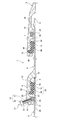
図1に示すように、1は、切管2と他の管3とを、接続管4を介して接続した管継手構造である。切管2は、施工現場で所定寸法(所定長さ)に切断加工して製作されており、切断端部を切管挿口6としている。また、他の管3は、一端部に挿口(図示省略)を有するとともに、他端部に受口7を有する直管状の規格管(鋳鉄管等)である。
A first embodiment of the present invention will be described below with reference to the drawings.
As shown in FIG. 1, reference numeral 1 denotes a pipe joint structure in which a
接続管4は、鋳鉄管であり、一端部に接続管受口8を有するとともに、他端部に接続管挿口9を有している。切管挿口6は接続管受口8に挿入され、接続管挿口9は受口7に挿入されている。切管挿口6の切断端部には、水密性を有する円環状の防食部材10(例えば防食ゴム等)が取り付けられている。
The connecting
接続管受口8には、切管挿口6と接続管受口8との離脱を防止する離脱防止手段11と、第1のシール材12とが設けられている。また、他の管3の受口7には、第2のシール材13とロックリング14(係止部材の一例)と心出し体15とが設けられている。
The connection
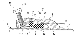
図2,図3に示すように、離脱防止手段11は、切管挿口6の外周面に管径方向から食込み移動可能な複数の抜止部材17と、切管挿口6と接続管受口8とが相対的に離脱方向へ移動しようとした際、抜止部材17を管径方向内方53側へ食込み移動させる食込み手段18とを有する。
As shown in FIGS. 2 and 3, the
接続管受口8の内周面の周方向に等間隔をおいた複数箇所には、管径方向内方53に向かって開口する複数の抜止用凹部19が形成されている。抜止部材17は、抜止用凹部19に、管径方向内方53へ食込み移動自在に嵌め込まれている。尚、各抜止部材17の内面には食込み突起20が形成されている。
A plurality of retaining
食込み手段18は、抜止部材17の外面に形成された受け面21と、受け面21を介して抜止部材17を管径方向内方53へ向かって押圧する複数の押圧ボルト22(押圧手段の一例)とを有している。受け面21は接続管受口8の奥側ほど管径方向外方へ向かって傾斜している。また、押圧ボルト22は、接続管受口8の内外両側に貫通するねじ孔23に螺合しており、受け面21に対して直交方向になるように傾斜しており、先端部が受け面21に当接している。
The biting means 18 includes a receiving
また、接続管受口8の内周面には、抜止用凹部19よりも奥側に位置する嵌め込み溝25と、嵌め込み溝25よりも奥側に位置する凹部26とがそれぞれ全周にわたり形成されている。嵌め込み溝25と凹部26との間には、管径方向内方53へ向って突出する凸部27が全周にわたり形成されている。
In addition, on the inner peripheral surface of the connection
図2,図4,図5に示すように、第1のシール材12は、切管挿口6と接続管受口8との間を全周にわたりシールするものであり、ゴム(弾性材の一例)製で円環状に形成されており、嵌め込み溝25に嵌め込まれるヒール部28と、接続管受口8の内周面と切管挿口6の外周面との間に挟まれるバルブ部29とを有している。ヒール部28は横断面形状(周方向に対して垂直な断面の形状)が方形をした環状の部材である。
As shown in FIGS. 2, 4, and 5, the first sealing
バルブ部29は、環状の部材であり、互いに接合された第1バルブ30と第2バルブ31とを備えている。図4,図5に示すように、第1のシール材12を接続管受口8から取り外した非圧縮状態(非使用状態)では、第1バルブ30の横断面形状は管軸心方向に長く且つ両端部に半径r1の半円部を有する長円形状であり、第2バルブ31の横断面形状は半径r2の円形状である。尚、上記半径r1は半径r2よりも小さく、第1バルブ30の厚さT1は第2バルブ31の厚さT2よりも薄い。また、第2バルブ31の横断面の直径(=2×r2)は凸部27の内周面と切管挿口6の外周面との管径方向の間隔Sよりも大きく形成されている。
The
第1バルブ30はヒール部28に接合され、第1バルブ30とヒール部28との接合部分の外周部にはシール材側凹部32が形成されている。尚、第1バルブ30の内径は切管挿口6の外径よりも僅かに小さく形成され、第1バルブ30の外径は凸部27の内径よりも僅かに大きく形成されている。
The
ヒール部28は、第1バルブ30に対して、接続管受口8の奥側とは反対の開口部側(手前側)に位置している。また、第1バルブ30と第2バルブ31との接合部分には、第1および第2バルブ30,31よりも薄いくびれ部33が形成されている。くびれ部33の内周面と外周面とにはそれぞれ、円弧状のシール材側凹部34,35が形成されている。
The
第2バルブ31は、第1バルブ30に対して接続管受口8の奥側に位置し、且つ、第1のシール材12を取り外した非圧縮状態では、第1バルブ30から管中心に向って傾斜している。尚、図5に示すように、第1バルブ30の第2バルブ31寄りの端部の半円部の中心P1と第2バルブ31の中心P2とを含む面をL1とし、上記中心P1を含み且つ第1のシール材12の径方向の面をL2とすると、面L2に対する面L1の傾斜角度Mは15〜35°に設定されている。さらに、第2バルブ31は、その内径dが切管挿口6の外径D(図2参照)よりも小さく設定され、且つ、くびれ部33の弾性変形により管径方向において拡縮自在である。また、ヒール部28の内径Jは第1バルブ30の内径Kよりも大きく設定されている。
The
第1バルブ30の外周部には、凸部27の内周面(接続管受口8の内周面)に圧接する第1シール部37が全周にわたり形成されている。また、第2バルブ31の内周部には、切管挿口6の外周面に圧接する第2シール部38が全周にわたり形成されている。第1シール部37の位置と第2シール部38の位置とは管軸心方向にずれている。また、凸部27の管軸心方向の長さは第2バルブ31を圧縮しない長さに設定されている。尚、ヒール部28はバルブ部47よりも硬質のゴムで形成されている。
A
図1に示すように、接続管挿口9の先端部の外周には抜止突部45が全周にわたり形成されている。尚、抜止突部45は接続管挿口9の先端面よりも所定距離だけ引き抜き方向へ後退した位置に形成されている。
As shown in FIG. 1, a retaining
また、他の管3の受口7の内周面には、嵌め込み溝46と、嵌め込み溝46よりも受口奥側に位置する凹部47と、凹部47よりも受口奥側に位置するロックリング収容溝48とがそれぞれ全周にわたり形成されている。嵌め込み溝46と凹部47との間には凸部49が形成されている。
Further, on the inner peripheral surface of the receiving port 7 of the other pipe 3, there are a
ロックリング14と心出し体15とはロックリング収容溝48に収容されている。ロックリング14は、周方向一つ割りの金属製リングであり、弾性的な縮径力を有することで、接続管挿口9の外周面に弾性的に抱き付くように構成されている。心出し体15は、ゴム等の弾性材からなり、ロックリング14の外周面とロックリング収容溝48の底面との間に配置されており、接続管挿口9が受口7に挿入されていないときにロックリング14を受口7に対して心出し状態に保持可能である。尚、接続管挿口9の抜止突部45は、ロックリング14に、受口奥側から係合可能である。
The
第2のシール材13は、受口7と接続管挿口9との間を全周にわたりシールするものであり、嵌め込み溝46に嵌め込まれるヒール部50と、受口7の内周面と接続管挿口9の外周面との間に挟まれるバルブ部51とを有している。尚、第2のシール材13は第1のシール材13と同じ構成を有している。
The
以下、上記構成における作用を説明する。
接続管4を介して切管2と他の管3とを接続する場合、図6に示すように、接続管4の接続管受口8内の嵌め込み溝25に第1のシール材12のヒール部28を嵌め込んで、第1のシール材12を接続管受口8内に装着する。
Hereinafter, the operation of the above configuration will be described.
When the
その後、切管2の切管挿口6を接続管受口8に挿入する。この際、図7に示すように、切管挿口6の先端は、第1バルブ30の内周に挿入され、第2バルブ31に接触して、第2バルブ31を挿入方向へ押す。これにより、図8に示すように、第2バルブ31が管径方向において拡大(拡径)され、拡大された第2バルブ31の外周と凹部26の底面との間には間隙52が全周にわたり形成される。その後、図9に示すように、切管挿口6をさらに接続管受口8に挿入することにより、切管2と接続管4とが接続される。
Thereafter, the cut
この際、第2バルブ31は、管径方向において拡大(拡径)された状態であるため、切管挿口6の外周面に張り付くとともに、第2バルブ31の拡径に付随して第1バルブ30が管径方向外向きに押される。これにより、第1バルブ30の第1シール部37が凸部27の内周面(接続管受口8の内周面)に圧接するとともに、第2バルブ31の第2シール部38が切管挿口6の外周面に圧接するため、接続管受口8と切管挿口6との間で高い水密性を保持することができ、切管挿口6と接続管受口8との間が第1のシール材12によって確実にシールされる。
At this time, since the
上記のように切管挿口6を接続管受口8に挿入した際、図4の仮想線で示すように、第1および第2バルブ30,31よりも薄いくびれ部33が変形することで、第2バルブ31が管径方向において拡大するため、第2バルブ31を管径方向において拡大させるのに要する力が低減され、これにより、切管挿口6を接続管受口8に挿入する際に要する挿入力(接合力)を低減することができる。
When the cut
また、図5に示すように、ヒール部28の内径Jは第1バルブ30の内径Kよりも大きいため、第1バルブ30が切管挿口6の外周面と凸部27の内周面との間で管径方向において圧縮される際、第1バルブ30の一部がヒール部28と切管挿口6との間に逃げることができる。このことによっても、上記挿入力(接合力)を低減することができる。
Further, as shown in FIG. 5, since the inner diameter J of the
さらに、図8に示すように、第1バルブ30が切管挿口6の外周面と凸部27の内周面との間で管径方向において圧縮されたとき、各シール材側凹部32,34,35(図5参照)が逃げ代となって第1バルブ30の圧縮量が減少する。これにより、切管挿口6が第1バルブ30の内周を管軸心方向へスムーズに移動するため、上記挿入力(接合力)を低減することができる。
Furthermore, as shown in FIG. 8, when the
また、図5に示すように、第1バルブ30の厚さT1は第2バルブ31の厚さT2よりも薄いため、切管挿口6が第1バルブ30の内周を管軸心方向へ移動する際、第1バルブ30の管径方向の圧縮量が小さくなり、切管挿口6が第1バルブ30の内周を管軸心方向へスムーズに移動し、上記挿入力(接合力)を低減することができる。
Further, as shown in FIG. 5, since the thickness T1 of the
さらに、図9に示すように、切管挿口6が第2バルブ31の内周を移動する際、間隙52が逃げ代となって、第2バルブ31が、切管挿口6に対して、管径方向の外向きに変位して逃げることができる。これにより、上記挿入力(接合力)をさらに低減することができる。
Furthermore, as shown in FIG. 9, when the cut
また、互いに接合された切管2と接続管4との内部に水圧が作用すると、図2に示すように、この水圧によってバルブ部29を接続管受口8の奥側から開口側(手前側)に押し出そうとする押出し力F1が管軸心方向に作用する。これに対して、第1シール部37の位置と第2シール部38の位置とが管軸心方向にずれているため、押出し力F1によってバルブ部29が接続管受口8の奥側から開口側に押し出されてしまうのを防止することができる。特に、第1シール部37の位置と第2シール部38の位置との管軸心方向におけるずれ量Aを大きくするほど、大きな押出し力F1に対して、バルブ部29が押し出されてしまうのを防止することができる。これにより、切管挿口6と接続管受口8との間の水密性が向上する。
Further, when water pressure acts inside the
また、第1バルブ30の第1シール部37は接続管受口8内の凸部27の内周面に圧接するため、第1バルブ30の外径を小さくして、凸部27の内径を小さくすることができ、これにより、凸部27と切管挿口6との隙間が小さくなり、水圧負荷時に第1のシール材12に作用する水圧の絶対値が小さくなる。したがって、高水圧負荷時でも、第1のシール材12が切管挿口6と接続管受口8との隙間から離脱し難くなる。
Further, since the
また、図5に示した第2バルブ31の横断面の直径(=2×r2)は凸部27の内周面と切管挿口6の外周面との管径方向の間隔Sよりも大きく形成されているため、バルブ部29が押出し力F1によって押されても、第2バルブ31は上記間隔Sを通過し難く、これによっても、バルブ部29が接続管受口8の奥側から開口側に押し出されてしまうのを防止することができる。
Further, the diameter (= 2 × r2) of the cross section of the
また、第2バルブ31の外周と凹部26の底面との間隙52にも水圧が作用するため、第2バルブ31には管中心に向いた押付力F2が作用し、これにより、第2バルブ31の第2シール部38が切管挿口6の外周面に強く押し付けられ、切管挿口6と接続管受口8との間の水密性がさらに向上する。
Further, since water pressure also acts on the
その後、図2に示すように、各押圧ボルト22を締め付けて、各抜止部材17を管径方向内方53へ向って押圧することにより、抜止部材17の食込み突起20を切管挿口6の外周面に食い込ませる。
After that, as shown in FIG. 2, each
また、図1に示すように、他の管3の受口7のロックリング収容溝48にロックリング14と心出し体15とを嵌め込み、さらに、受口7の嵌め込み溝46に第2のシール材13のヒール部50を嵌め込んで、第2のシール材13を受口7内に装着する。その後、接続管挿口9を受口7に挿入し、接続管挿口9の抜止突部45をロックリング14の受口開口側から受口奥側へ通過させる。
Further, as shown in FIG. 1, the
この際、接続管挿口9の抜止突部45は第2のシール材13の内周を通過するが、第1のシール材12と同様に、接続管挿口9を受口7に挿入する際に要する挿入力(接合力)を低減することができる。また、第1のシール材12と同様に、第2のシール材13によって受口7と接続管挿口9との間の水密性が向上する。
At this time, the retaining
また、地震等の地盤変動によって管継手構造1に離脱力(抜け出し力)が作用して、接続管4と他の管3とが相対的に離脱移動しようとした際、抜止突部45がロックリング14に受口奥側から係合することにより、接続管挿口9と受口7との相対的な離脱移動が強力に阻止される。
In addition, when the disconnection force (extraction force) acts on the pipe joint structure 1 due to ground fluctuation such as an earthquake and the like, and the
さらに、上記離脱力が作用して、切管2と接続管4とが相対的に離脱移動しようとした際、食込み手段18によって各抜止部材17が管径方向内方53側へ食込み移動し、食込み突起20が切管挿口6の外周面に食い込むため、切管挿口6と接続管受口8との接続が強力に維持される。
Furthermore, when the above detachment force acts and the cutting
また、図1に示すように、切管挿口6の切断端面は塗装されていないが、防食部材10が取り付けられているため、腐食を防止することができる。
次に、本発明における第2の実施の形態を、図10を参照して説明する。
Moreover, as shown in FIG. 1, although the cut end surface of the cut
Next, a second embodiment of the present invention will be described with reference to FIG.
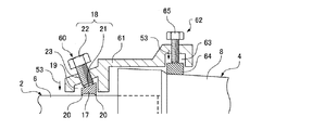
離脱防止手段60は、切管挿口6と接続管受口8とに外嵌された円環状の離脱防止リング61に設けられている。上記第1の実施の形態と同様に、離脱防止手段60は、複数の抜止部材17と、食込み手段18とを有する。また、複数の抜止用凹部19は離脱防止リング61の管軸心方向における一端部内周面に形成され、抜止部材17は抜止用凹部19に嵌め込まれている。尚、食込み手段18は受け面21と押圧ボルト22とを有している。
The
離脱防止リング61の管軸心方向における他端部には、離脱防止リング61を接続管受口8の外周に固定する固定手段62が備えられている。固定手段62は、離脱防止リング61の内周に全周にわたり形成された固定溝63と、固定溝63に嵌め込まれた固定リング64と、固定リング64を管径方向内方53へ向けて押圧する複数の固定ボルト65とを有している。
Fixing means 62 for fixing the
固定リング64は、周方向一つ割り構造の金属製リングであり、接続管受口8に外嵌されている。また、固定ボルト65は離脱防止リング61の周方向に等間隔をおいた複数箇所に設けられている。
The fixing
以下、上記構成における作用を説明する。
固定リング64を固定溝63内に嵌め込んだ状態で、離脱防止リング61を接続管受口8に外嵌し、固定ボルト65を締め付けて固定リング64を管径方向内方53へ向けて押圧する。これにより、固定リング64が接続管受口8の外周面に当接して押圧されるため、離脱防止リング61が接続管受口8の外周に固定される。
Hereinafter, the operation of the above configuration will be described.
With the fixing
次に、抜止部材17を抜止用凹部19に嵌め込んだ状態で、切管挿口6を接続管受口8に挿入し、その後、押圧ボルト22を締め付けて、抜止部材17を管径方向内方53へ向って押圧することにより、食込み突起20を切管挿口6の外周面に食い込ませる。
Next, in a state where the retaining
地震等の地盤変動によって管継手構造1に離脱力が作用して、切管2と接続管4とが相対的に離脱移動しようとした際、食込み手段18によって各抜止部材17が管径方向内方53側へ食込み移動し、食込み突起20が切管挿口6の外周面に食い込むため、切管挿口6と接続管受口8との接続が強力に維持される。
When the detachment force acts on the pipe joint structure 1 due to ground fluctuation such as an earthquake, and the cutting
1 管継手構造
2 切管
3 他の管
4 接続管
6 切管挿口
7 受口
8 接続管受口
9 接続管挿口
11,60 離脱防止手段
12 第1のシール材
14 ロックリング(係止部材)
17 抜止部材
18 食込み手段
25 嵌め込み溝
26 凹部
27 凸部
28 ヒール部
29 バルブ部
30 第1バルブ
31 第2バルブ
32,34,35 シール材側凹部
33 くびれ部
37 第1シール部
38 第2シール部
45 抜止突部
52 間隙
61 離脱防止リング
T1 第1バルブの管径方向の厚さ
T2 第2バルブの管径方向の厚さ
DESCRIPTION OF SYMBOLS 1 Pipe
17
Claims (9)
接続管は一端に接続管受口を有するとともに他端に接続管挿口を有し、
切管の切断端部が切管挿口として接続管の接続管受口に挿入され、
接続管の接続管挿口が他の管の受口に挿入され、
接続管挿口には、他の管の受口内周に設けられた係止部材に受口奥側から係合可能な抜止突部が設けられ、
切管挿口と接続管受口との離脱を防止する離脱防止手段が備えられ、
切管挿口と接続管受口との間は弾性材からなる環状のシール材によって全周にわたりシールされ、
シール材は、接続管受口の内周面に形成された嵌め込み溝に嵌め込まれるヒール部と、接続管受口の内周面と切管挿口の外周面との間に挟まれるバルブ部とを有し、
バルブ部は互いに接合された第1バルブと第2バルブとを備え、
第1バルブの外周部に、接続管受口の内周面に圧接する第1シール部が形成され、
第2バルブの内周部に、切管挿口の外周面に圧接する第2シール部が形成され、
第1バルブがヒール部に接合され、
第1バルブと第2バルブとの接合部分にはくびれ部が形成され、
第2バルブは、第1バルブに対して接続管受口の奥側に位置し、且つ、第1バルブから管中心に向って傾斜しており、
ヒール部は、第1バルブに対して、接続管受口の奥側とは反対の開口部側に位置し、
第2バルブは、その内径が切管挿口の外径よりも小さく設定され、且つ、くびれ部の変形により管径方向において拡縮自在であり、
接続管受口の内周面には、嵌め込み溝よりも奥側に位置する凹部が形成され、
第1バルブの管径方向の厚さは第2バルブの管径方向の厚さよりも薄く、
第2バルブの外周と接続管受口の凹部の底面との間に間隙が形成されていることを特徴とする管継手構造。 A pipe joint structure in which a cut tube having a cut end portion manufactured by cutting to a predetermined size at a construction site and a receiving port formed at the end portion of another pipe are connected via a connecting pipe. ,
The connecting pipe has a connecting pipe receptacle at one end and a connecting pipe insertion opening at the other end,
The cut end of the cut tube is inserted into the connection tube receiving port of the connection tube as a cut tube insertion port,
The connecting pipe insertion port of the connecting pipe is inserted into the receiving port of another pipe,
The connection pipe insertion opening is provided with a locking protrusion that can be engaged from the receiving port back side to a locking member provided on the inner periphery of the receiving port of the other tube.
A detachment preventing means for preventing detachment between the cut tube insertion port and the connection tube receiving port is provided,
Between the cut tube insertion port and the connection tube receiving port is sealed over the entire circumference by an annular sealing material made of an elastic material,
The sealing material includes a heel portion that is fitted into a fitting groove formed on the inner peripheral surface of the connection pipe receiving port, and a valve portion that is sandwiched between the inner peripheral surface of the connection pipe receiving port and the outer peripheral surface of the cut tube insertion port. Have
The valve portion includes a first valve and a second valve joined to each other,
A first seal portion that is in pressure contact with the inner peripheral surface of the connection pipe receiving port is formed on the outer peripheral portion of the first valve,
A second seal portion that is in pressure contact with the outer peripheral surface of the cut tube insertion opening is formed on the inner peripheral portion of the second valve,
The first valve is joined to the heel,
A constriction is formed at the joint between the first valve and the second valve,
The second valve is located on the back side of the connection pipe receiving port with respect to the first valve, and is inclined from the first valve toward the pipe center,
The heel portion is located on the opening side opposite to the back side of the connection pipe receiving port with respect to the first valve,
The second valve, the inner diameter is smaller than the outer diameter of the cut pipe spigot, and, Ri scaled freely der in pipe diameter direction by the deformation of the constricted portion,
On the inner peripheral surface of the connection pipe receptacle, a recess located on the back side of the fitting groove is formed,
The thickness of the first valve in the radial direction is thinner than the thickness of the second valve in the radial direction,
A pipe joint structure characterized in that a gap is formed between the outer periphery of the second valve and the bottom surface of the recess of the connection pipe receiving port .
第1シール部は凸部の内周面に圧接し、
第1シール部の位置と第2シール部の位置とが管軸心方向にずれていることを特徴とする請求項1記載の管継手構造。 On the inner peripheral surface of the connection pipe receptacle, a convex portion is formed between the fitting groove and the concave portion,
The first seal portion is in pressure contact with the inner peripheral surface of the convex portion,
The pipe joint structure according to claim 1, wherein the position of the first seal part and the position of the second seal part are shifted in the axial direction of the pipe.
切管の切断端部が切管挿口として挿入される接続管受口が一端に備えられ、
他の管の受口に挿入される接続管挿口が他端に備えられ、
接続管挿口には、他の管の受口内周に設けられた係止部材に受口奥側から係合可能な抜止突部が設けられ、
切管挿口と接続管受口との離脱が離脱防止手段によって防止され、
切管挿口と接続管受口との間を全周にわたりシールする弾性材からなる環状のシール材が接続管受口内に配設され、
シール材は、接続管受口の内周面に形成された嵌め込み溝内に嵌め込まれるヒール部と、接続管受口の内周面と切管挿口の外周面との間に挟まれるバルブ部とを有し、
バルブ部は互いに接合された第1バルブと第2バルブとを備え、
第1バルブの外周部に、接続管受口の内周面に圧接する第1シール部が形成され、
第2バルブの内周部に、切管挿口の外周面に圧接する第2シール部が形成され、
第1バルブがヒール部に接合され、
第1バルブと第2バルブとの接合部分にはくびれ部が形成され、
第2バルブは、第1バルブに対して接続管受口の奥側に位置し、且つ、第1バルブから管中心に向って傾斜しており、
ヒール部は、第1バルブに対して、接続管受口の奥側とは反対の開口部側に位置し、
第2バルブは、その内径が切管挿口の外径よりも小さく設定され、且つ、くびれ部の変形により管径方向において拡縮自在であり、
接続管受口の内周面には、嵌め込み溝よりも奥側に位置する凹部が形成され、
第1バルブの管径方向の厚さは第2バルブの管径方向の厚さよりも薄く、
第2バルブの外周と接続管受口の凹部の底面との間に間隙が形成されることを特徴とする接続管。 A connecting pipe that connects a cut tube having a cut end manufactured by cutting into a predetermined dimension at a construction site and a receiving port formed at the end of another pipe,
A connection pipe receiving port into which the cut end of the cut tube is inserted as a cut tube insertion port is provided at one end,
A connecting tube insertion port to be inserted into the receiving port of another tube is provided at the other end,
The connection pipe insertion opening is provided with a locking protrusion that can be engaged from the receiving port back side to a locking member provided on the inner periphery of the receiving port of the other tube.
Detachment between the cutting tube insertion port and the connection tube receiving port is prevented by the separation preventing means,
An annular sealing material made of an elastic material that seals between the cut tube insertion port and the connection tube receiving port over the entire circumference is disposed in the connection tube receiving port,
The sealing material includes a heel portion that is fitted in a fitting groove formed on the inner peripheral surface of the connection tube receiving port, and a valve portion that is sandwiched between the inner peripheral surface of the connection tube receiving port and the outer peripheral surface of the cut tube insertion port. And
The valve portion includes a first valve and a second valve joined to each other,
A first seal portion that is in pressure contact with the inner peripheral surface of the connection pipe receiving port is formed on the outer peripheral portion of the first valve,
A second seal portion that is in pressure contact with the outer peripheral surface of the cut tube insertion opening is formed on the inner peripheral portion of the second valve,
The first valve is joined to the heel,
A constriction is formed at the joint between the first valve and the second valve,
The second valve is located on the back side of the connection pipe receiving port with respect to the first valve, and is inclined from the first valve toward the pipe center,
The heel portion is located on the opening side opposite to the back side of the connection pipe receiving port with respect to the first valve,
The second valve has its inner diameter is smaller than the outer diameter of the cut pipe spigot, and, Ri scaled freely der in pipe diameter direction by the deformation of the constricted portion,
On the inner peripheral surface of the connection pipe receptacle, a recess located on the back side of the fitting groove is formed,
The thickness of the first valve in the radial direction is thinner than the thickness of the second valve in the radial direction,
A connection pipe characterized in that a gap is formed between the outer periphery of the second valve and the bottom surface of the recess of the connection pipe receiving port.
Priority Applications (21)
| Application Number | Priority Date | Filing Date | Title |
|---|---|---|---|
| JP2009138737A JP5377095B2 (en) | 2009-06-10 | 2009-06-10 | Fitting structure and connecting pipe |
| US13/146,256 US8573654B2 (en) | 2009-01-27 | 2010-01-22 | Pipe joint |
| CN201310088677.0A CN103133793B (en) | 2009-01-27 | 2010-01-22 | Tube joint |
| EP10735744.4A EP2392845B1 (en) | 2009-01-27 | 2010-01-22 | Pipe joint |
| KR1020117016070A KR101488752B1 (en) | 2009-01-27 | 2010-01-22 | Pipe joint and pipe connecting apparatus |
| CN201080005536.2A CN102301172B (en) | 2009-01-27 | 2010-01-22 | Pipe joint |
| KR1020137025902A KR101585909B1 (en) | 2009-01-27 | 2010-01-22 | Pipe joint |
| CN201310089272.9A CN103174889B (en) | 2009-01-27 | 2010-01-22 | Pipe joint |
| CN201410165455.9A CN104075050B (en) | 2009-01-27 | 2010-01-22 | Pipe joint |
| CN201310089167.5A CN103148293B (en) | 2009-01-27 | 2010-01-22 | Pipe joint |
| KR1020137025901A KR101514689B1 (en) | 2009-01-27 | 2010-01-22 | Pipe joint |
| CN201410161002.9A CN103925432B (en) | 2009-01-27 | 2010-01-22 | Pipe joint |
| PCT/JP2010/050755 WO2010087275A1 (en) | 2009-01-27 | 2010-01-22 | Pipe joint |
| TW103130993A TWI530636B (en) | 2009-01-27 | 2010-01-27 | Pipe fittings and fittings for the locking ring |
| TW103130995A TWI542806B (en) | 2009-01-27 | 2010-01-27 | Joints and fittings for pipe joints |
| TW103130994A TWI542805B (en) | 2009-01-27 | 2010-01-27 | Pipe fittings |
| TW099102264A TWI487862B (en) | 2009-01-27 | 2010-01-27 | Pipe fittings |
| US14/022,299 US9488300B2 (en) | 2009-01-27 | 2013-09-10 | Pipe joint |
| US14/220,433 US9719618B2 (en) | 2009-01-27 | 2014-03-20 | Pipe joint |
| US14/974,118 US10520119B2 (en) | 2009-01-27 | 2015-12-18 | Pipe joint |
| US14/974,062 US10006572B2 (en) | 2009-01-27 | 2015-12-18 | Pipe joint |
Applications Claiming Priority (1)
| Application Number | Priority Date | Filing Date | Title |
|---|---|---|---|
| JP2009138737A JP5377095B2 (en) | 2009-06-10 | 2009-06-10 | Fitting structure and connecting pipe |
Publications (2)
| Publication Number | Publication Date |
|---|---|
| JP2010286017A JP2010286017A (en) | 2010-12-24 |
| JP5377095B2 true JP5377095B2 (en) | 2013-12-25 |
Family
ID=43541875
Family Applications (1)
| Application Number | Title | Priority Date | Filing Date |
|---|---|---|---|
| JP2009138737A Active JP5377095B2 (en) | 2009-01-27 | 2009-06-10 | Fitting structure and connecting pipe |
Country Status (1)
| Country | Link |
|---|---|
| JP (1) | JP5377095B2 (en) |
Family Cites Families (8)
| Publication number | Priority date | Publication date | Assignee | Title |
|---|---|---|---|---|
| JPH039598Y2 (en) * | 1986-02-17 | 1991-03-11 | ||
| JPH0424232Y2 (en) * | 1987-09-14 | 1992-06-08 | ||
| JPH0799231B2 (en) * | 1991-07-16 | 1995-10-25 | コスモ工機株式会社 | Pipe fitting |
| JPH05231570A (en) * | 1992-02-20 | 1993-09-07 | Kubota Corp | Rubber ring for slip-off preventive tube joint |
| JP3392986B2 (en) * | 1995-05-17 | 2003-03-31 | コスモ工機株式会社 | Fluid pipe detachment prevention device |
| NL1000584C2 (en) * | 1995-06-16 | 1996-12-19 | Wavin Bv | Pipe part with a socket end provided with a sealing assembly and sealing assembly. |
| JPH1038157A (en) * | 1996-07-19 | 1998-02-13 | Aron Kasei Co Ltd | Coupling for connecting polyvinyl chloride pipe and ceramic pipe |
| JP2006170296A (en) * | 2004-12-15 | 2006-06-29 | Kubota Corp | Pipe joint and method of joining the same |
-
2009
- 2009-06-10 JP JP2009138737A patent/JP5377095B2/en active Active
Also Published As
| Publication number | Publication date |
|---|---|
| JP2010286017A (en) | 2010-12-24 |
Similar Documents
| Publication | Publication Date | Title |
|---|---|---|
| JP6735123B2 (en) | Pipe joint and pipe joining method | |
| TWI628386B (en) | Pipe joint, separation preventive member, and method of connecting pipes | |
| JP5455381B2 (en) | Sealing material | |
| JP5455382B2 (en) | Pipe fittings and seals | |
| JP5534821B2 (en) | Sealing material with separation prevention function and separation prevention pipe joint | |
| WO2015111303A1 (en) | Separation-preventing pipe joint and pipeline configuration member | |
| JP2006118712A (en) | Coupling assembly with connection indicator | |
| JP6525636B2 (en) | How to connect backup ring, fittings and pipes | |
| JP4781220B2 (en) | Pipe fitting and backup ring used for it | |
| JP5455383B2 (en) | Pipe fitting | |
| JP5377095B2 (en) | Fitting structure and connecting pipe | |
| JP6735124B2 (en) | Pipe fitting and separation prevention member | |
| JP2004211831A (en) | Pipe joint structure | |
| WO2011043113A1 (en) | Seal part with detachment prevention function and detachment prevention pipe joint | |
| JP2004169829A (en) | Piping joint structure | |
| JP4212341B2 (en) | Pipe joint spacer and pipe joint | |
| JP2005315384A (en) | Pipe connection structure and setting method of work machine in piping to insertion pipe part | |
| JP2010261562A (en) | Pipe joint, packing ring, and method for assembling pipe joint | |
| JP2007255684A (en) | Pipe joint | |
| JP6764668B2 (en) | Pipe fittings and pipe joining methods | |
| JP2005308139A (en) | Pipe joint structure | |
| JP2005337269A (en) | Separation preventing pipe joint | |
| JP2006009997A (en) | Tube fitting | |
| JP2758098B2 (en) | Captive fittings | |
| JP5950989B2 (en) | Sealing material and pipe fittings |
Legal Events
| Date | Code | Title | Description |
|---|---|---|---|
| A621 | Written request for application examination |
Free format text: JAPANESE INTERMEDIATE CODE: A621 Effective date: 20120326 |
|
| A131 | Notification of reasons for refusal |
Free format text: JAPANESE INTERMEDIATE CODE: A131 Effective date: 20130604 |
|
| A521 | Written amendment |
Free format text: JAPANESE INTERMEDIATE CODE: A523 Effective date: 20130730 |
|
| TRDD | Decision of grant or rejection written | ||
| A01 | Written decision to grant a patent or to grant a registration (utility model) |
Free format text: JAPANESE INTERMEDIATE CODE: A01 Effective date: 20130827 |
|
| A61 | First payment of annual fees (during grant procedure) |
Free format text: JAPANESE INTERMEDIATE CODE: A61 Effective date: 20130924 |
|
| R150 | Certificate of patent or registration of utility model |
Ref document number: 5377095 Country of ref document: JP Free format text: JAPANESE INTERMEDIATE CODE: R150 Free format text: JAPANESE INTERMEDIATE CODE: R150 |