JP5368694B2 - Heat exchanger for cooling cracked gas - Google Patents
Heat exchanger for cooling cracked gas Download PDFInfo
- Publication number
- JP5368694B2 JP5368694B2 JP2007299862A JP2007299862A JP5368694B2 JP 5368694 B2 JP5368694 B2 JP 5368694B2 JP 2007299862 A JP2007299862 A JP 2007299862A JP 2007299862 A JP2007299862 A JP 2007299862A JP 5368694 B2 JP5368694 B2 JP 5368694B2
- Authority
- JP
- Japan
- Prior art keywords
- water
- heat exchanger
- gas
- cracked gas
- cooling
- Prior art date
- Legal status (The legal status is an assumption and is not a legal conclusion. Google has not performed a legal analysis and makes no representation as to the accuracy of the status listed.)
- Active
Links
- 238000001816 cooling Methods 0.000 title claims abstract description 22
- XLYOFNOQVPJJNP-UHFFFAOYSA-N water Substances O XLYOFNOQVPJJNP-UHFFFAOYSA-N 0.000 claims abstract description 52
- 239000002826 coolant Substances 0.000 claims abstract description 16
- 238000009835 boiling Methods 0.000 claims abstract description 12
- VGGSQFUCUMXWEO-UHFFFAOYSA-N Ethene Chemical compound C=C VGGSQFUCUMXWEO-UHFFFAOYSA-N 0.000 claims abstract description 7
- 239000005977 Ethylene Substances 0.000 claims abstract description 7
- 238000005192 partition Methods 0.000 claims description 25
- 230000002093 peripheral effect Effects 0.000 claims description 2
- 238000005336 cracking Methods 0.000 abstract description 13
- 239000012466 permeate Substances 0.000 abstract description 2
- 239000007789 gas Substances 0.000 description 55
- ATUOYWHBWRKTHZ-UHFFFAOYSA-N Propane Chemical compound CCC ATUOYWHBWRKTHZ-UHFFFAOYSA-N 0.000 description 2
- 239000000498 cooling water Substances 0.000 description 2
- -1 ethylene, propylene, butadiene Chemical class 0.000 description 2
- 238000001704 evaporation Methods 0.000 description 2
- VNWKTOKETHGBQD-UHFFFAOYSA-N methane Chemical compound C VNWKTOKETHGBQD-UHFFFAOYSA-N 0.000 description 2
- 239000012071 phase Substances 0.000 description 2
- 229930195734 saturated hydrocarbon Natural products 0.000 description 2
- 229930195735 unsaturated hydrocarbon Natural products 0.000 description 2
- OTMSDBZUPAUEDD-UHFFFAOYSA-N Ethane Chemical compound CC OTMSDBZUPAUEDD-UHFFFAOYSA-N 0.000 description 1
- 229910000831 Steel Inorganic materials 0.000 description 1
- 239000001273 butane Substances 0.000 description 1
- 238000006243 chemical reaction Methods 0.000 description 1
- 239000011248 coating agent Substances 0.000 description 1
- 238000000576 coating method Methods 0.000 description 1
- 230000008878 coupling Effects 0.000 description 1
- 238000010168 coupling process Methods 0.000 description 1
- 238000005859 coupling reaction Methods 0.000 description 1
- 230000001419 dependent effect Effects 0.000 description 1
- 238000007599 discharging Methods 0.000 description 1
- 230000008020 evaporation Effects 0.000 description 1
- 239000007791 liquid phase Substances 0.000 description 1
- IJDNQMDRQITEOD-UHFFFAOYSA-N n-butane Chemical compound CCCC IJDNQMDRQITEOD-UHFFFAOYSA-N 0.000 description 1
- OFBQJSOFQDEBGM-UHFFFAOYSA-N n-pentane Natural products CCCCC OFBQJSOFQDEBGM-UHFFFAOYSA-N 0.000 description 1
- 239000003345 natural gas Substances 0.000 description 1
- 239000004033 plastic Substances 0.000 description 1
- 229920003023 plastic Polymers 0.000 description 1
- 239000001294 propane Substances 0.000 description 1
- 238000000197 pyrolysis Methods 0.000 description 1
- 239000002994 raw material Substances 0.000 description 1
- 229920006395 saturated elastomer Polymers 0.000 description 1
- 239000010959 steel Substances 0.000 description 1
- 230000007704 transition Effects 0.000 description 1
- 238000003466 welding Methods 0.000 description 1
Images

Classifications
-
- F—MECHANICAL ENGINEERING; LIGHTING; HEATING; WEAPONS; BLASTING
- F01—MACHINES OR ENGINES IN GENERAL; ENGINE PLANTS IN GENERAL; STEAM ENGINES
- F01K—STEAM ENGINE PLANTS; STEAM ACCUMULATORS; ENGINE PLANTS NOT OTHERWISE PROVIDED FOR; ENGINES USING SPECIAL WORKING FLUIDS OR CYCLES
- F01K3/00—Plants characterised by the use of steam or heat accumulators, or intermediate steam heaters, therein
- F01K3/18—Plants characterised by the use of steam or heat accumulators, or intermediate steam heaters, therein having heaters
- F01K3/188—Plants characterised by the use of steam or heat accumulators, or intermediate steam heaters, therein having heaters using heat from a specified chemical reaction
-
- F—MECHANICAL ENGINEERING; LIGHTING; HEATING; WEAPONS; BLASTING
- F22—STEAM GENERATION
- F22B—METHODS OF STEAM GENERATION; STEAM BOILERS
- F22B1/00—Methods of steam generation characterised by form of heating method
- F22B1/02—Methods of steam generation characterised by form of heating method by exploitation of the heat content of hot heat carriers
- F22B1/18—Methods of steam generation characterised by form of heating method by exploitation of the heat content of hot heat carriers the heat carrier being a hot gas, e.g. waste gas such as exhaust gas of internal-combustion engines
- F22B1/1838—Methods of steam generation characterised by form of heating method by exploitation of the heat content of hot heat carriers the heat carrier being a hot gas, e.g. waste gas such as exhaust gas of internal-combustion engines the hot gas being under a high pressure, e.g. in chemical installations
-
- F—MECHANICAL ENGINEERING; LIGHTING; HEATING; WEAPONS; BLASTING
- F22—STEAM GENERATION
- F22B—METHODS OF STEAM GENERATION; STEAM BOILERS
- F22B1/00—Methods of steam generation characterised by form of heating method
- F22B1/02—Methods of steam generation characterised by form of heating method by exploitation of the heat content of hot heat carriers
- F22B1/18—Methods of steam generation characterised by form of heating method by exploitation of the heat content of hot heat carriers the heat carrier being a hot gas, e.g. waste gas such as exhaust gas of internal-combustion engines
- F22B1/1884—Hot gas heating tube boilers with one or more heating tubes
-
- F—MECHANICAL ENGINEERING; LIGHTING; HEATING; WEAPONS; BLASTING
- F22—STEAM GENERATION
- F22B—METHODS OF STEAM GENERATION; STEAM BOILERS
- F22B37/00—Component parts or details of steam boilers
- F22B37/02—Component parts or details of steam boilers applicable to more than one kind or type of steam boiler
- F22B37/40—Arrangements of partition walls in flues of steam boilers, e.g. built-up from baffles
-
- F—MECHANICAL ENGINEERING; LIGHTING; HEATING; WEAPONS; BLASTING
- F22—STEAM GENERATION
- F22B—METHODS OF STEAM GENERATION; STEAM BOILERS
- F22B9/00—Steam boilers of fire-tube type, i.e. the flue gas from a combustion chamber outside the boiler body flowing through tubes built-in in the boiler body
- F22B9/10—Steam boilers of fire-tube type, i.e. the flue gas from a combustion chamber outside the boiler body flowing through tubes built-in in the boiler body the boiler body being disposed substantially horizontally, e.g. at the side of the combustion chamber
-
- F—MECHANICAL ENGINEERING; LIGHTING; HEATING; WEAPONS; BLASTING
- F28—HEAT EXCHANGE IN GENERAL
- F28D—HEAT-EXCHANGE APPARATUS, NOT PROVIDED FOR IN ANOTHER SUBCLASS, IN WHICH THE HEAT-EXCHANGE MEDIA DO NOT COME INTO DIRECT CONTACT
- F28D7/00—Heat-exchange apparatus having stationary tubular conduit assemblies for both heat-exchange media, the media being in contact with different sides of a conduit wall
- F28D7/0066—Multi-circuit heat-exchangers, e.g. integrating different heat exchange sections in the same unit or heat-exchangers for more than two fluids
- F28D7/0083—Multi-circuit heat-exchangers, e.g. integrating different heat exchange sections in the same unit or heat-exchangers for more than two fluids with units having particular arrangement relative to a supplementary heat exchange medium, e.g. with interleaved units or with adjacent units arranged in common flow of supplementary heat exchange medium
- F28D7/0091—Multi-circuit heat-exchangers, e.g. integrating different heat exchange sections in the same unit or heat-exchangers for more than two fluids with units having particular arrangement relative to a supplementary heat exchange medium, e.g. with interleaved units or with adjacent units arranged in common flow of supplementary heat exchange medium the supplementary medium flowing in series through the units
-
- F—MECHANICAL ENGINEERING; LIGHTING; HEATING; WEAPONS; BLASTING
- F28—HEAT EXCHANGE IN GENERAL
- F28F—DETAILS OF HEAT-EXCHANGE AND HEAT-TRANSFER APPARATUS, OF GENERAL APPLICATION
- F28F9/00—Casings; Header boxes; Auxiliary supports for elements; Auxiliary members within casings
- F28F9/22—Arrangements for directing heat-exchange media into successive compartments, e.g. arrangements of guide plates
-
- C—CHEMISTRY; METALLURGY
- C10—PETROLEUM, GAS OR COKE INDUSTRIES; TECHNICAL GASES CONTAINING CARBON MONOXIDE; FUELS; LUBRICANTS; PEAT
- C10G—CRACKING HYDROCARBON OILS; PRODUCTION OF LIQUID HYDROCARBON MIXTURES, e.g. BY DESTRUCTIVE HYDROGENATION, OLIGOMERISATION, POLYMERISATION; RECOVERY OF HYDROCARBON OILS FROM OIL-SHALE, OIL-SAND, OR GASES; REFINING MIXTURES MAINLY CONSISTING OF HYDROCARBONS; REFORMING OF NAPHTHA; MINERAL WAXES
- C10G2400/00—Products obtained by processes covered by groups C10G9/00 - C10G69/14
- C10G2400/20—C2-C4 olefins
-
- F—MECHANICAL ENGINEERING; LIGHTING; HEATING; WEAPONS; BLASTING
- F28—HEAT EXCHANGE IN GENERAL
- F28D—HEAT-EXCHANGE APPARATUS, NOT PROVIDED FOR IN ANOTHER SUBCLASS, IN WHICH THE HEAT-EXCHANGE MEDIA DO NOT COME INTO DIRECT CONTACT
- F28D21/00—Heat-exchange apparatus not covered by any of the groups F28D1/00 - F28D20/00
- F28D2021/0019—Other heat exchangers for particular applications; Heat exchange systems not otherwise provided for
- F28D2021/0075—Other heat exchangers for particular applications; Heat exchange systems not otherwise provided for for syngas or cracked gas cooling systems
-
- F—MECHANICAL ENGINEERING; LIGHTING; HEATING; WEAPONS; BLASTING
- F28—HEAT EXCHANGE IN GENERAL
- F28D—HEAT-EXCHANGE APPARATUS, NOT PROVIDED FOR IN ANOTHER SUBCLASS, IN WHICH THE HEAT-EXCHANGE MEDIA DO NOT COME INTO DIRECT CONTACT
- F28D7/00—Heat-exchange apparatus having stationary tubular conduit assemblies for both heat-exchange media, the media being in contact with different sides of a conduit wall
- F28D7/16—Heat-exchange apparatus having stationary tubular conduit assemblies for both heat-exchange media, the media being in contact with different sides of a conduit wall the conduits being arranged in parallel spaced relation
- F28D7/1607—Heat-exchange apparatus having stationary tubular conduit assemblies for both heat-exchange media, the media being in contact with different sides of a conduit wall the conduits being arranged in parallel spaced relation with particular pattern of flow of the heat exchange media, e.g. change of flow direction
-
- F—MECHANICAL ENGINEERING; LIGHTING; HEATING; WEAPONS; BLASTING
- F28—HEAT EXCHANGE IN GENERAL
- F28F—DETAILS OF HEAT-EXCHANGE AND HEAT-TRANSFER APPARATUS, OF GENERAL APPLICATION
- F28F9/00—Casings; Header boxes; Auxiliary supports for elements; Auxiliary members within casings
- F28F9/22—Arrangements for directing heat-exchange media into successive compartments, e.g. arrangements of guide plates
- F28F2009/222—Particular guide plates, baffles or deflectors, e.g. having particular orientation relative to an elongated casing or conduit
- F28F2009/226—Transversal partitions
Landscapes
- Engineering & Computer Science (AREA)
- Mechanical Engineering (AREA)
- General Engineering & Computer Science (AREA)
- Physics & Mathematics (AREA)
- Thermal Sciences (AREA)
- Chemical & Material Sciences (AREA)
- Combustion & Propulsion (AREA)
- Life Sciences & Earth Sciences (AREA)
- Sustainable Development (AREA)
- Sustainable Energy (AREA)
- Chemical Kinetics & Catalysis (AREA)
- Heat-Exchange Devices With Radiators And Conduit Assemblies (AREA)
- Organic Low-Molecular-Weight Compounds And Preparation Thereof (AREA)
- Separation By Low-Temperature Treatments (AREA)
- Hydrogen, Water And Hydrids (AREA)
Abstract
Description
本発明は、請求項1の前文の特徴を有する分解ガスを冷却するための熱交換器に関する。 The invention relates to a heat exchanger for cooling cracked gas having the features of the preamble of claim 1.
熱分解炉またはエチレン分解炉は、プラスチック産業用のエチレン施設の内部で、原料のエチレン、プロピレン、ブタジエン他を製造するための主要コンポーネントとなる。原料として使用されるのは飽和炭化水素、主としてエタン、プロパン、ブタン、天然ガス、ナフサまたはガス油である。飽和炭化水素から不飽和炭化水素への転換は分解炉の分解管内で、しかも入口温度500〜680℃、出口温度775〜875℃で1.5〜5バールの圧力範囲内で起きる。 The pyrolysis furnace or ethylene cracking furnace is the main component for producing raw materials ethylene, propylene, butadiene, etc. within the ethylene facility for the plastics industry. The feedstock used is saturated hydrocarbons, mainly ethane, propane, butane, natural gas, naphtha or gas oil. The conversion of saturated hydrocarbons to unsaturated hydrocarbons takes place in the cracking tube of the cracking furnace and in the pressure range of 1.5-5 bar with an inlet temperature of 500-680 ° C. and an outlet temperature of 775-875 ° C.
分解炉の出口に後置された分解ガス冷却器において不飽和炭化水素、いわゆる分解ガスは、775〜875℃から約350〜450℃に冷却されて高圧蒸気または低圧蒸気を生成する。その際、「冷却水」は相応する圧力において沸点を有する。冷却は液相から気相への相転移に基づいて起きる。蒸気は例えば蒸気タービン用のエチレン施設において利用される。 Unsaturated hydrocarbons, so-called cracked gases, are cooled from 775 to 875 ° C. to about 350 to 450 ° C. in a cracked gas cooler placed at the outlet of the cracking furnace to produce high pressure steam or low pressure steam. The “cooling water” then has a boiling point at the corresponding pressure. Cooling occurs based on a phase transition from the liquid phase to the gas phase. Steam is utilized, for example, in ethylene facilities for steam turbines.
分解ガスを冷却して蒸気を生成することは、約350〜450℃への完全冷却が単に1つの分解ガス冷却器において行われる単段システムにおいて行われるか、または前後で接続される2つの分解ガス冷却器内で歩進的冷却、例えば第1ステップでは875℃から550℃に、第2ステップでは550℃から350℃へと行われる2段システムにおいて行われる。分解ガス冷却器は一次冷却器、二次冷却器との相応する名称を有する。 Cooling the cracked gas to produce steam can be done in a single stage system where complete cooling to about 350-450 ° C. is only done in one cracked gas cooler, or two cracks connected back and forth. In step cooling in a gas cooler, for example in a two-stage system where the first step is from 875 ° C. to 550 ° C. and the second step is from 550 ° C. to 350 ° C. The cracked gas cooler has the corresponding names of primary cooler and secondary cooler.
付加的に、分解ガスのさらなる冷却はボイラ給水予熱器において単段システムでも2段システムでも行われる。その際、蒸気はもはや生成されず、「冷却水」、ボイラ給水は一次冷却器および二次冷却器用に極力沸点近傍に予熱される。予熱されたボイラ給水を一次分解ガス冷却器および二次分解ガス冷却器に供給することは、ボイラ給水を沸点に加熱する蒸気ドラムを介して間接的に行われる。 In addition, further cooling of the cracked gas takes place in the boiler feed water preheater in either a single stage system or a two stage system. At that time, steam is no longer generated, and “cooling water”, boiler feed water is preheated as close to the boiling point as possible for the primary and secondary coolers. Supplying the preheated boiler feedwater to the primary cracking gas cooler and the secondary cracking gas cooler is performed indirectly via a steam drum that heats the boiler feedwater to the boiling point.
特許文献1により公知の分解ガス冷却器では、蒸発器である第1冷却段において分解ガスが沸騰水によって冷却され、過熱器である第2冷却段において蒸気によって冷却される。通常どおり分解ガス冷却器の下流側に付加的冷却器を設けることができ、この冷却器において分解ガスは給水によってさらに冷却される。特許文献1により公知の分解ガス冷却器の1変更態様では、蒸発器と過熱器が共通の外被内に配置され、或る冷却段から別の冷却段への冷却媒体の溢流を防止する隔壁によって相互に分離されている。
本発明の課題は、分解ガスのガス流出側にある部分空間の内部で冷却が一層効率的となりかつ機器構造が低減されるように、共通する外被の内部に2つの部分空間を含む前文に記載した分解ガス冷却用熱交換器を構成することである。 The subject of the present invention is the preamble which includes two partial spaces inside a common jacket so that cooling is more efficient and the equipment structure is reduced inside the partial space on the gas outlet side of the cracked gas. It is to constitute the described heat exchanger for cooling the cracked gas.
この課題は、前文に係る熱交換器において本発明によれば請求項1の特徴部分の特徴によって解決される。本発明の有利な諸構成は従属請求項の対象である。 This problem is solved by the features of the characterizing part of claim 1 according to the invention in the heat exchanger according to the preamble. Advantageous configurations of the invention are the subject of the dependent claims.
分解ガスのガス流入側にある熱交換器部分空間は蒸発器として役立ち、沸騰水の沸点近傍に至るまで分解ガスを冷却する。分解ガスは引き続き、分解ガスのガス流出側にあって予熱器として役立つ部分空間に達し、そこで分解ガスは冷たい給水によって水の沸点よりもかなり下へとさらに冷却される。これにより、分解ガスの冷却は全体として一層効率的となる。その際に暖められた給水は蒸気ドラムに供給されてそこで沸点に加熱されるか、または「漏れる」管板として働く隔壁によって蒸発器部内に直接流れるかのいずれかである。冷却媒体を意図的に透過するよう構成された隔壁は部分空間の間で均圧をもたらす。 The heat exchanger partial space on the gas inflow side of the cracked gas serves as an evaporator and cools the cracked gas to the vicinity of the boiling point of boiling water. The cracked gas continues to a partial space on the gas outlet side of the cracked gas that serves as a preheater, where the cracked gas is further cooled by the cold feed water well below the boiling point of water. This makes the cooling of the cracked gas more efficient as a whole. The heated feed water is either fed to the steam drum where it is heated to the boiling point or flows directly into the evaporator section by a partition that acts as a “leaking” tubesheet. A partition configured to intentionally permeate the cooling medium provides pressure equalization between the subspaces.
さらに、蒸発器と予熱器を1つの共通する集成装置へとまとめることによって、従来個別であった給水予熱器が蒸発器に一体化されることによって分解ガス冷却の機器構造が簡素化され、これにより冷却列の内部で冷却器一式が省かれ、また蒸発器と給水予熱器との間の分解ガス管路が省かれ、蒸気ドラムに至る配管を短くすることができる。 Further, by integrating the evaporator and the preheater into one common collecting device, the conventional feed water preheater is integrated into the evaporator, thereby simplifying the equipment structure for cracked gas cooling. This eliminates the set of coolers inside the cooling train, eliminates the cracked gas conduit between the evaporator and the feed water preheater, and shortens the piping leading to the steam drum.
蒸発器から予熱器に至る結合が省かれることによって、本来なら管流出部の蒸発器と管流入部の予熱器とガス流出室およびガス流入室への流れとによって引き起こされるであろうガス側圧力損失は生じない。これにより冷却器内で分解ガスの総圧力損失が減少し、分解ガス中のエチレン、プロピレン、ブタジエン他の収率が高まるとともに、冷却器の運転期間も長くなる。 By eliminating the coupling from the evaporator to the preheater, the gas side pressure that would otherwise be caused by the evaporator at the pipe outlet, the preheater at the pipe inlet, and the flow to the gas outlet and gas inlet chambers. There is no loss. This reduces the total pressure loss of cracked gas in the cooler, increases the yield of ethylene, propylene, butadiene, etc. in the cracked gas, and increases the operating period of the cooler.
本発明の1実施例が図面に示してあり、以下で詳しく説明される。 One embodiment of the present invention is illustrated in the drawings and will be described in detail below.
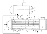
図示した熱交換器はエチレン施設において分解ガスを冷却するのに役立つ。この熱交換器は直線的熱交換管1の管束からなり、これらの熱交換管は管束の両側で各1つの管板2、3内で保持されている。図面には理解し易いように熱交換管1の幾つかのみが図示されている。各管板2、3に穴が設けられており、熱交換管1の各1つがこれらの穴に嵌挿され、溶接部によって管板2、3と溶接されている。管束を取り囲んでいる外側外被4は各管板2、3と一緒に、冷却媒体を貫流させる内部空間を限定する。
The illustrated heat exchanger serves to cool cracked gas in an ethylene facility. This heat exchanger consists of a bundle of straight heat exchange tubes 1, which are held in one tube sheet 2, 3 on each side of the bundle. Only some of the heat exchange tubes 1 are shown in the drawing for easy understanding. Holes are provided in the respective tube plates 2 and 3, and each one of the heat exchange tubes 1 is fitted into these holes and welded to the tube plates 2 and 3 by welding portions. The
管板2、3にガス流入側およびガス流出側で各1つの端室、流入室5および流出室6が続く。流入室5と流出室6は分解ガスを給排するための短管をそれぞれ備えている。熱交換器の部品はすべて耐熱鋼から作製されている。
The tube plates 2, 3 are each connected with one end chamber, an
流入室5を通して到来する高温の分解ガスは管板2に衝突し、管板2の穴を通して熱交換管1に流入し、別の末端の管板3を通して熱交換器の冷却領域から離れる。冷却された分解ガスは流出室6を介して排出される。図示矢印は流れ方向を示す。
The hot cracked gas coming through the
熱交換器の内部空間は隔壁7によって2つの部分空間8、9に分割されており、熱交換器の内部に2つの冷却部が生じており、冷却部はそれぞれ独自の冷却媒体を付加され、蒸発部もしくは予熱部として役立つ。 The internal space of the heat exchanger is divided into two partial spaces 8 and 9 by the partition wall 7, two cooling parts are generated inside the heat exchanger, and each cooling part has its own cooling medium added, Useful as an evaporating part or preheating part.
寝かせて配置された熱交換器の、分割ガスのガス流入側にある部分空間8は、下面側に複数の冷却媒体供給短管10、上面側に複数の冷却媒体排出短管11を備えている。高圧を受けた沸騰水が冷却媒体として役立ち、この水は水と蒸気との分離に役立つ水/蒸気ドラム12から取り出される。このため供給短管10に供給管路13が接続されており、この供給管路は水/蒸気ドラム12の水空間14から出発している。排出短管11が排出管路15と結合されており、この排出管路は水/蒸気ドラム12の水空間14に別の個所で注ぎ、分解ガスとの熱交換で生成される飽和蒸気を排出する。水/蒸気ドラム12内で分離された蒸気は、水/蒸気ドラム12の蒸気空間16から出発する蒸気管路17を介して排出される。
The partial space 8 on the gas inflow side of the divided gas of the heat exchanger that is laid down includes a plurality of cooling medium supply
寝かせて配置された熱交換器のガス流出側にある部分空間9は、下面側で管板3の近傍に単数または複数の供給短管18、上面側で隔壁7の近傍に単数または複数の排出短管19を備えている。給水は供給短管18を介して部分空間9に供給される。部分空間9内に方向転換板20が相互に離間し平行に、上下にずらして配置されており、方向転換板は邪魔板として働き、給水を分解ガスと向流で部分空間9内に通す。給水は分解ガスと熱交換して予熱され、排出短管19に接続された排出管路21を介して水/蒸気ドラム12の水空間14に導かれる。
The partial space 9 on the gas outflow side of the heat exchanger that is laid down is one or more supply
蒸発部と予熱部を共通の熱交換集成装置へとまとめると、熱交換器と水/蒸気ドラム12との間の給排部が短縮される。この配置により、水/蒸気ドラム12を熱交換器の外被4上に直接組付けることが可能となる。これにより得られるコンパクトな構造ユニットによって、配管と配管組付け時間を節約することができる。
If the evaporation section and the preheating section are combined into a common heat exchange assembly, the supply / discharge section between the heat exchanger and the water /
両方の部分空間8、9の間の隔壁7は非担持部材であり、その役目は部分空間8、9内で流れを別々に保つことだけである。隔壁7が穴22を備えており、穴の直径が熱交換管1の外側直径よりも僅かに大きく、熱交換管1は遊隙23をもって隔壁7に挿通されている。隔壁7の外側直径が外被4の内側直径よりも小さく、組込状態のとき隔壁7と外被4との間に隙間24が生じる。隔壁7は熱交換管1からなる管束とともに外被4内に押し込むことができる。通常寸法の熱交換器の場合、隔壁7と外被4との間の隙間24は数ミリメートル、例えば2mm、熱交換管1と隔壁7の穴22との間の遊隙23は1mm未満、例えば0.6mmである。図2では隙間24と遊隙23が過比例的に大きく図示されている。
The partition 7 between the two partial spaces 8, 9 is a non-supporting member, whose role is only to keep the flow separate in the partial spaces 8, 9. The partition wall 7 is provided with a hole 22, the diameter of the hole is slightly larger than the outer diameter of the heat exchange tube 1, and the heat exchange tube 1 is inserted into the partition wall 7 with a gap 23. The outer diameter of the partition wall 7 is smaller than the inner diameter of the
隔壁7と外被4との間の隙間24と、熱交換管1の周面と隔壁7の穴22との間の遊隙23とにより、一方の部分空間8、9から他方の部分空間への各冷却媒体の通過に対して隔壁7が透過性となる。従って隔壁7は「漏れる」管板として働く。
From one partial space 8, 9 to the other partial space by a
給水はガス流出側にある部分空間9にポンプを介して供給され、給水が受けている圧力は確かに僅かに変動し、またはガス流入側にある部分空間8内の圧力よりも常に高い。つまり一般に圧力差が常に存在する。この圧力差は、ガス流出側にある部分空間9から、意識的に漏れ状態に保たれた隔壁7を通してガス流入側にある部分空間8へと水が移ることによって補償される。ガス流出側にある部分空間9から流出する漏れ水はガス流入側にある部分空間8内で蒸発し、やはり水/蒸気ドラム12に達する。
The feed water is supplied to the partial space 9 on the gas outflow side via a pump, and the pressure received by the feed water certainly varies slightly or is always higher than the pressure in the partial space 8 on the gas inflow side. That is, generally there is always a pressure difference. This pressure difference is compensated by water moving from the partial space 9 on the gas outflow side to the partial space 8 on the gas inflow side through the partition wall 7 that is intentionally kept in a leaking state. The leaked water flowing out from the partial space 9 on the gas outflow side evaporates in the partial space 8 on the gas inflow side and reaches the water /
1 熱交換管
2、3 管板
4 外被
5、6 分解ガス給排用端室
7 隔壁
8、9 部分空間
10 冷却媒体供給短管
11 排出短管
12 水/蒸気ドラム
13 供給管路
14 水空間
15 排出管路
16 蒸気空間
17 隔壁
18 冷却媒体供給短管
19 排出短管
20 方向転換板
21 排出管路
22 穴
23 遊隙
24 隙間
DESCRIPTION OF SYMBOLS 1 Heat exchange pipe 2, 3
Claims (4)
Applications Claiming Priority (2)
| Application Number | Priority Date | Filing Date | Title |
|---|---|---|---|
| DE102006055973.8 | 2006-11-24 | ||
| DE102006055973A DE102006055973A1 (en) | 2006-11-24 | 2006-11-24 | Heat exchanger for cooling cracked gas |
Publications (2)
| Publication Number | Publication Date |
|---|---|
| JP2008145097A JP2008145097A (en) | 2008-06-26 |
| JP5368694B2 true JP5368694B2 (en) | 2013-12-18 |
Family
ID=39326389
Family Applications (1)
| Application Number | Title | Priority Date | Filing Date |
|---|---|---|---|
| JP2007299862A Active JP5368694B2 (en) | 2006-11-24 | 2007-11-19 | Heat exchanger for cooling cracked gas |
Country Status (6)
| Country | Link |
|---|---|
| US (1) | US7784433B2 (en) |
| EP (1) | EP1939412B1 (en) |
| JP (1) | JP5368694B2 (en) |
| AT (1) | ATE484653T1 (en) |
| DE (2) | DE102006055973A1 (en) |
| ES (1) | ES2351522T3 (en) |
Families Citing this family (29)
| Publication number | Priority date | Publication date | Assignee | Title |
|---|---|---|---|---|
| ES2374080T3 (en) * | 2007-07-05 | 2012-02-13 | Ib.Ntec | THERMODYNAMIC SYSTEM THAT PRACTICES A HEAT PRODUCTION DEVICE THROUGH CIRCULATION OF A PRESSURE FLUID THROUGH A PLURALITY OF PIPES. |
| CN101769658B (en) * | 2009-12-17 | 2012-12-12 | 中国石油化工股份有限公司 | Fluid distribution method for rapid-cooling heat exchanger |
| CN101865446B (en) * | 2010-06-17 | 2012-01-11 | 南京国昌化工科技有限公司 | Horizontal-type bushing-type high temperature exhaust-heat recovery unit capable of generating saturated vapor and superheated vapor at the same time |
| CA3092028C (en) | 2012-01-13 | 2022-08-30 | Lummus Technology Llc | Process for separating hydrocarbon compounds |
| US9428978B2 (en) * | 2012-06-28 | 2016-08-30 | Carbon Energy Limited | Method for shortening an injection pipe for underground coal gasification |
| US9969660B2 (en) | 2012-07-09 | 2018-05-15 | Siluria Technologies, Inc. | Natural gas processing and systems |
| US20150247658A1 (en) * | 2012-09-26 | 2015-09-03 | Trane International Inc. | Low refrigerant high performing subcooler |
| US9598328B2 (en) | 2012-12-07 | 2017-03-21 | Siluria Technologies, Inc. | Integrated processes and systems for conversion of methane to multiple higher hydrocarbon products |
| WO2015081122A2 (en) | 2013-11-27 | 2015-06-04 | Siluria Technologies, Inc. | Reactors and systems for oxidative coupling of methane |
| CA3123783A1 (en) | 2014-01-08 | 2015-07-16 | Lummus Technology Llc | Ethylene-to-liquids systems and methods |
| US10377682B2 (en) | 2014-01-09 | 2019-08-13 | Siluria Technologies, Inc. | Reactors and systems for oxidative coupling of methane |
| AU2015204709B2 (en) | 2014-01-09 | 2019-08-15 | Lummus Technology Llc | Oxidative coupling of methane implementations for olefin production |
| US10793490B2 (en) | 2015-03-17 | 2020-10-06 | Lummus Technology Llc | Oxidative coupling of methane methods and systems |
| US9334204B1 (en) | 2015-03-17 | 2016-05-10 | Siluria Technologies, Inc. | Efficient oxidative coupling of methane processes and systems |
| US20160289143A1 (en) | 2015-04-01 | 2016-10-06 | Siluria Technologies, Inc. | Advanced oxidative coupling of methane |
| US9328297B1 (en) | 2015-06-16 | 2016-05-03 | Siluria Technologies, Inc. | Ethylene-to-liquids systems and methods |
| WO2017065947A1 (en) | 2015-10-16 | 2017-04-20 | Siluria Technologies, Inc. | Separation methods and systems for oxidative coupling of methane |
| FR3044081B1 (en) * | 2015-11-20 | 2017-12-29 | Technip France | COOL FLOW COOLING SYSTEM AND METHOD THEREOF |
| EP3442934A4 (en) | 2016-04-13 | 2019-12-11 | Siluria Technologies, Inc. | Oxidative coupling of methane for olefin production |
| EP3267100B1 (en) * | 2016-07-08 | 2021-04-14 | L'air Liquide, Société Anonyme Pour L'Étude Et L'exploitation Des Procédés Georges Claude | Steam creation system |
| DE102016013459A1 (en) * | 2016-11-12 | 2018-05-17 | Linde Aktiengesellschaft | Process for changing the temperature of a fluid by means of a shell-and-tube heat exchanger and shell-and-tube heat exchanger |
| US20180169561A1 (en) | 2016-12-19 | 2018-06-21 | Siluria Technologies, Inc. | Methods and systems for performing chemical separations |
| CN106839827A (en) * | 2017-01-19 | 2017-06-13 | 南京天华化学工程有限公司 | A kind of multi-functional cracking rapid-cooling heat exchanger |
| CA3064016C (en) | 2017-05-23 | 2024-01-16 | Lummus Technology Llc | Integration of oxidative coupling of methane processes |
| EP3406970A1 (en) | 2017-05-26 | 2018-11-28 | ALFA LAVAL OLMI S.p.A. | Vapour and liquid drum for a shell-and-tube heat exchanger |
| RU2020102298A (en) | 2017-07-07 | 2021-08-10 | Люммус Текнолоджи Ллс | SYSTEMS AND METHODS FOR OXIDATIVE COMBINATIONS OF METHANE |
| DE102018002086A1 (en) | 2018-03-09 | 2019-09-12 | Borsig Gmbh | quench |
| CN110056848B (en) * | 2018-04-23 | 2024-05-03 | 新能能源有限公司 | High-temperature high-pressure flue gas waste heat utilization system |
| EP4053452B1 (en) | 2021-03-05 | 2023-09-27 | ALFA LAVAL OLMI S.p.A. | Process heat recovery system |
Family Cites Families (21)
| Publication number | Priority date | Publication date | Assignee | Title |
|---|---|---|---|---|
| DE2711897C3 (en) * | 1977-03-18 | 1980-01-10 | Davy International Ag, 6000 Frankfurt | Process and device for the catalytic oxidation of gaseous sulfur compounds to sulfur trioxide |
| JPS5752793A (en) * | 1980-09-12 | 1982-03-29 | Mitsubishi Heavy Ind Ltd | Rapid cooling type heat exchanger |
| US4352341A (en) * | 1981-04-06 | 1982-10-05 | The M.W. Kellogg Company | Waste heat boiler and steam superheater system |
| DE3302304A1 (en) * | 1983-01-25 | 1984-07-26 | Borsig Gmbh, 1000 Berlin | HEAT EXCHANGER FOR COOLING HOT GASES, ESPECIALLY FROM THE AMMONIA SYNTHESIS |
| US4488513A (en) * | 1983-08-29 | 1984-12-18 | Texaco Development Corp. | Gas cooler for production of superheated steam |
| DE3429366C2 (en) * | 1984-08-09 | 1990-09-13 | L. & C. Steinmüller GmbH, 5270 Gummersbach | Cracked gas cooler |
| DE3643303A1 (en) | 1986-12-18 | 1988-06-30 | Uhde Gmbh | DEVICE FOR HEAT EXCHANGE, ESPECIALLY BETWEEN SYNTHESIS GAS AND BOILER FEED WATER |
| DE3643801A1 (en) * | 1986-12-20 | 1988-07-07 | Borsig Gmbh | METHOD AND DEVICE FOR COOLING FUSE GAS |
| DE3913731A1 (en) * | 1989-04-26 | 1990-10-31 | Borsig Gmbh | HEAT EXCHANGER FOR COOLING FUSE GAS |
| JP2778878B2 (en) * | 1991-09-12 | 1998-07-23 | 株式会社日本触媒 | Method for producing ethylene oxide |
| DK173540B1 (en) * | 1994-06-29 | 2001-02-05 | Topsoe Haldor As | Waste heat boiler |
| DE19534823C2 (en) * | 1995-09-20 | 2002-08-22 | Ruhr Oel Gmbh | Shell and tube heat exchangers |
| US5813453A (en) * | 1996-06-01 | 1998-09-29 | Deutsche Babcock-Borsig Ag | Heat exchanger for cooling cracked gas |
| JP3885904B2 (en) * | 1997-05-06 | 2007-02-28 | 臼井国際産業株式会社 | EGR gas cooling device |
| JPH1113549A (en) * | 1997-06-23 | 1999-01-19 | Isuzu Motors Ltd | Egr cooler |
| DE19811905C2 (en) | 1998-03-18 | 2000-03-30 | Papierfabrik Scheufelen Gmbh & | Method and device for measuring the breakage behavior of cardboard, in particular playing cards |
| BE1012128A3 (en) * | 1998-08-21 | 2000-05-02 | Blommaert Paul | Combined steam boiler and water supply pre-heater of the type with a flare pipe known as a "combination boiler" |
| DE10062320A1 (en) * | 2000-12-14 | 2002-06-20 | Borsig Gmbh | Heat recovery boiler for cooling hot synthesis gas |
| DE10233818B4 (en) * | 2002-07-25 | 2007-05-24 | Uhde Gmbh | Waste heat boiler for a Claus plant |
| US7090816B2 (en) * | 2003-07-17 | 2006-08-15 | Kellogg Brown & Root Llc | Low-delta P purifier for nitrogen, methane, and argon removal from syngas |
| DE102005057674B4 (en) * | 2005-12-01 | 2008-05-08 | Alstom Technology Ltd. | waste heat boiler |
-
2006
- 2006-11-24 DE DE102006055973A patent/DE102006055973A1/en not_active Withdrawn
-
2007
- 2007-11-02 ES ES07033540T patent/ES2351522T3/en active Active
- 2007-11-02 DE DE502007005333T patent/DE502007005333D1/en active Active
- 2007-11-02 EP EP07033540A patent/EP1939412B1/en active Active
- 2007-11-02 AT AT07033540T patent/ATE484653T1/en active
- 2007-11-19 JP JP2007299862A patent/JP5368694B2/en active Active
- 2007-11-20 US US11/943,140 patent/US7784433B2/en active Active
Also Published As
| Publication number | Publication date |
|---|---|
| US20080121383A1 (en) | 2008-05-29 |
| DE102006055973A1 (en) | 2008-05-29 |
| ATE484653T1 (en) | 2010-10-15 |
| EP1939412A1 (en) | 2008-07-02 |
| JP2008145097A (en) | 2008-06-26 |
| ES2351522T3 (en) | 2011-02-07 |
| EP1939412B1 (en) | 2010-10-13 |
| DE502007005333D1 (en) | 2010-11-25 |
| US7784433B2 (en) | 2010-08-31 |
Similar Documents
| Publication | Publication Date | Title |
|---|---|---|
| JP5368694B2 (en) | Heat exchanger for cooling cracked gas | |
| CN106574825B (en) | Shell-and-tube heat exchanger | |
| CA2735836C (en) | Tube bundle heat exchanger for controlling a wide performance range | |
| JP5746353B2 (en) | Waste heat boiler | |
| EP3262363B1 (en) | Waste heat boiler system and method for cooling a process gas | |
| KR102295920B1 (en) | Cylindrical multi-pipe equipment with bypass | |
| RU2403522C2 (en) | Method for heating and/or evaporation of organic medium and heat exchanging unit for extraction of heat from flow of hot gas | |
| US6148908A (en) | Heat exchanger for cooling a hot process gas | |
| JP2023537989A (en) | SHELL AND TUBE HEAT EXCHANGER, HEAT EXCHANGE METHOD, AND USE OF HEAT EXCHANGER | |
| CN106705710A (en) | Heat exchanger | |
| EP1282802B1 (en) | Process for heating steam | |
| JP5611278B2 (en) | Ship boiler | |
| JP3977840B2 (en) | Waste heat boiler for Claus plant | |
| KR102601560B1 (en) | Evaporation assembly of liquid gases to supply combustion gases for engines | |
| RU2334187C1 (en) | Heat exchanger | |
| GB2447974A (en) | Heat exchanger of a condensing boiler | |
| SU1143926A1 (en) | Steam-water heat exchanger | |
| CZ303921B6 (en) | Vertical separation steam generator |
Legal Events
| Date | Code | Title | Description |
|---|---|---|---|
| A621 | Written request for application examination |
Free format text: JAPANESE INTERMEDIATE CODE: A621 Effective date: 20101108 |
|
| A521 | Request for written amendment filed |
Free format text: JAPANESE INTERMEDIATE CODE: A523 Effective date: 20111107 |
|
| A977 | Report on retrieval |
Free format text: JAPANESE INTERMEDIATE CODE: A971007 Effective date: 20120514 |
|
| A131 | Notification of reasons for refusal |
Free format text: JAPANESE INTERMEDIATE CODE: A131 Effective date: 20120522 |
|
| A601 | Written request for extension of time |
Free format text: JAPANESE INTERMEDIATE CODE: A601 Effective date: 20120817 |
|
| A602 | Written permission of extension of time |
Free format text: JAPANESE INTERMEDIATE CODE: A602 Effective date: 20120822 |
|
| A601 | Written request for extension of time |
Free format text: JAPANESE INTERMEDIATE CODE: A601 Effective date: 20120921 |
|
| A602 | Written permission of extension of time |
Free format text: JAPANESE INTERMEDIATE CODE: A602 Effective date: 20120926 |
|
| A601 | Written request for extension of time |
Free format text: JAPANESE INTERMEDIATE CODE: A601 Effective date: 20121022 |
|
| A602 | Written permission of extension of time |
Free format text: JAPANESE INTERMEDIATE CODE: A602 Effective date: 20121025 |
|
| A521 | Request for written amendment filed |
Free format text: JAPANESE INTERMEDIATE CODE: A523 Effective date: 20121122 |
|
| A02 | Decision of refusal |
Free format text: JAPANESE INTERMEDIATE CODE: A02 Effective date: 20130205 |
|
| A521 | Request for written amendment filed |
Free format text: JAPANESE INTERMEDIATE CODE: A523 Effective date: 20130605 |
|
| A521 | Request for written amendment filed |
Free format text: JAPANESE INTERMEDIATE CODE: A523 Effective date: 20130621 |
|
| A911 | Transfer to examiner for re-examination before appeal (zenchi) |
Free format text: JAPANESE INTERMEDIATE CODE: A911 Effective date: 20130712 |
|
| TRDD | Decision of grant or rejection written | ||
| A01 | Written decision to grant a patent or to grant a registration (utility model) |
Free format text: JAPANESE INTERMEDIATE CODE: A01 Effective date: 20130905 |
|
| A61 | First payment of annual fees (during grant procedure) |
Free format text: JAPANESE INTERMEDIATE CODE: A61 Effective date: 20130913 |
|
| R150 | Certificate of patent or registration of utility model |
Free format text: JAPANESE INTERMEDIATE CODE: R150 Ref document number: 5368694 Country of ref document: JP Free format text: JAPANESE INTERMEDIATE CODE: R150 |
|
| R250 | Receipt of annual fees |
Free format text: JAPANESE INTERMEDIATE CODE: R250 |
|
| R250 | Receipt of annual fees |
Free format text: JAPANESE INTERMEDIATE CODE: R250 |
|
| R250 | Receipt of annual fees |
Free format text: JAPANESE INTERMEDIATE CODE: R250 |
|
| R250 | Receipt of annual fees |
Free format text: JAPANESE INTERMEDIATE CODE: R250 |
|
| R250 | Receipt of annual fees |
Free format text: JAPANESE INTERMEDIATE CODE: R250 |
|
| R250 | Receipt of annual fees |
Free format text: JAPANESE INTERMEDIATE CODE: R250 |
|
| R250 | Receipt of annual fees |
Free format text: JAPANESE INTERMEDIATE CODE: R250 |
|
| R250 | Receipt of annual fees |
Free format text: JAPANESE INTERMEDIATE CODE: R250 |
|
| R250 | Receipt of annual fees |
Free format text: JAPANESE INTERMEDIATE CODE: R250 |