JP5366991B2 - Immersion nozzle for continuous casting - Google Patents
Immersion nozzle for continuous casting Download PDFInfo
- Publication number
- JP5366991B2 JP5366991B2 JP2011035329A JP2011035329A JP5366991B2 JP 5366991 B2 JP5366991 B2 JP 5366991B2 JP 2011035329 A JP2011035329 A JP 2011035329A JP 2011035329 A JP2011035329 A JP 2011035329A JP 5366991 B2 JP5366991 B2 JP 5366991B2
- Authority
- JP
- Japan
- Prior art keywords
- nozzle
- continuous casting
- steps
- pair
- immersion nozzle
- Prior art date
- Legal status (The legal status is an assumption and is not a legal conclusion. Google has not performed a legal analysis and makes no representation as to the accuracy of the status listed.)
- Expired - Fee Related
Links
Images


Description
本発明は、連続鋳造用浸漬ノズルに関するものである。 The present invention relates to an immersion nozzle for continuous casting.
連続鋳造用浸漬ノズルは、タンディッシュからモールドに溶鋼を流入するためのものであり、タンディッシュ・モールド間に配設される。モールドの湯面はセンサにて検知されており、湯面が下がると溶鋼を多く流入させ、湯面が上がると溶鋼の流入量を減少させるように制御されている。 The continuous casting immersion nozzle is for flowing molten steel from the tundish into the mold, and is disposed between the tundish mold. The molten metal surface of the mold is detected by a sensor, and when the molten metal surface falls, a large amount of molten steel flows in, and when the molten metal surface rises, the amount of molten steel flowing in is reduced.
従って、湯面にうねりなど流入量に起因しない上下変動が生じると、良好な鋳造速度の制御ができない。このようなうねりは、溶鋼の落下流入に際してノズル内で偏流が発生し、左右の吐出口から異なる量の吐出がなされること(片流れ現象)に起因するものであり、それを抑制するために、例えば図7および図8に示すように、ノズル内孔の内面31の全周に渡って環状段差32,33を設けた連続鋳造用浸漬ノズル30が使用されている(特開平11−123509号公報)。これらの環状段差32,33は、溶鋼をノズル内孔34の中心に誘導することで偏流を抑制するよう作用するものである。
Therefore, if vertical fluctuations not caused by the inflow amount such as undulations occur on the molten metal surface, good casting speed control cannot be performed. Such swell is caused by the occurrence of uneven flow in the nozzle when the molten steel falls and flows in, and different amounts of discharge from the left and right discharge ports (single flow phenomenon). For example, as shown in FIGS. 7 and 8, a continuous
しかし、全周に渡って環状段差が設けられていると、溶鋼がノズル内孔の中心に集中して速くなり過ぎ、これが逆に湯面変動の原因にもなっていた。 However, if an annular step is provided over the entire circumference, the molten steel concentrates at the center of the nozzle bore and becomes too fast, which in turn causes the fluctuation of the molten metal surface.
そこで、本願発明者らは、左右の吐出口から均一に吐出でき、湯面変動の少ない段差を鋭気研究した結果、本発明を完成するに至った。すなわち、本発明の課題は、溶鋼の流入速度を緩和できると共に、左右の吐出口からの吐出量を均一化でき、うねり等に起因する湯面変動がより少ない連続鋳造用浸漬ノズルを提供することにある。 Accordingly, the inventors of the present application have conducted a keen study on a level difference that can be uniformly discharged from the right and left discharge ports and have little fluctuation in the molten metal surface, and as a result, the present invention has been completed. That is, an object of the present invention is to provide an immersion nozzle for continuous casting that can alleviate the inflow speed of molten steel, can equalize the discharge amount from the left and right discharge ports, and has less fluctuation of the molten metal surface due to swells and the like. It is in.
上記課題を解決するものは、ノズル本体と、該ノズル本体内に設けられ溶鋼が流通するためのノズル内孔と、前記ノズル本体の下部に対向して対称に設けられた一対の吐出口とを有し、前記ノズル内孔は、前記一対の吐出口の上部に対向して対称に設けられ、メニスカスの上下に渡って80〜250mmの範囲内で連続した一対の段差を有し、反吐出口側には段差が設けられていないことを特徴とする連続鋳造用浸漬ノズルである。 What solves the above-described problems includes a nozzle body, a nozzle inner hole provided in the nozzle body for flowing molten steel , and a pair of discharge ports provided symmetrically facing the lower portion of the nozzle body. has the nozzle holes, to face provided symmetrically on the top of the pair of discharge ports, it has a pair of stepped continuous within the 80~250mm over and below the meniscus, vomiting outlet Is a continuous casting immersion nozzle characterized in that no step is provided .
前記ノズル内孔の前記一対の段差の上部には、対向して設けられた一対の第2段差が形成されていることが好ましい。前記ノズル内孔の前記一対の段差の上部には、環状に形成された第2段差が設けられていてもよい。前記一対の段差は、前記ノズル内孔の内周において45〜135°の範囲内にそれぞれ形成されていることが好ましい。前記一対の段差は、厚みが5〜15mmの範囲内にそれぞれ形成されていることが好ましい。前記一対の段差は、上下方向の長さが80〜250mmの範囲内にそれぞれ形成されていることが好ましい。 It is preferable that a pair of second steps provided opposite to each other is formed on top of the pair of steps in the nozzle inner hole. A second step formed in an annular shape may be provided above the pair of steps in the nozzle inner hole. The pair of steps is preferably formed within a range of 45 to 135 ° on the inner periphery of the nozzle inner hole. The pair of steps is preferably formed within a range of 5 to 15 mm in thickness. It is preferable that the pair of steps are respectively formed within a range of 80 to 250 mm in length in the vertical direction.
請求項1に記載した連続鋳造用ノズルによれば、溶鋼の流入速度を緩和できると共に、左右の吐出口からの吐出量をより均一化でき、湯面にうねりや流入量に起因しない上下変動がより少ない連続鋳造用浸漬ノズルを構成できる。
請求項2に記載した連続鋳造用ノズルによれば、上記請求項1の効果をより奏する連続鋳造用浸漬ノズルとなる。
請求項3に記載した連続鋳造用ノズルによれば、溶鋼の偏流をより抑制できる連続鋳造用浸漬ノズルとなる。
According to the continuous casting nozzle described in claim 1, the flow rate of the molten steel can be reduced, the discharge amount from the left and right discharge ports can be made more uniform, and vertical fluctuations not caused by undulation or inflow amount on the molten metal surface. Fewer nozzles for continuous casting can be constructed.
According to the nozzle for continuous casting described in
According to the nozzle for continuous casting described in
本発明では、ノズル内孔に、一対の吐出口の上部に対向して設けられメニスカスの上下に渡って連続した一対の段差を形成したことにより、メニスカス付近に至った溶鋼が、吐出口側ではノズル内孔を縮径する段差の表面に沿ってモールド内に誘導され、他方、段差が設けられていない反吐出口側ではノズル内孔の表面に沿ってモールド内に流入するため、環状段差が設けられた場合に比して溶鋼の流入速度が緩和されると共に、一対の段差は対向した位置に(ノズル本体の中心軸に対して対称の位置に)設けられているため、左右の吐出口からの吐出量も均一化され、うねり等に起因した湯面変動がより少ない連続鋳造用浸漬ノズルを実現した。 In the present invention, by forming a pair of steps in the nozzle inner hole facing the upper portions of the pair of discharge ports and continuing up and down the meniscus, the molten steel reaching the vicinity of the meniscus is formed on the discharge port side. Guided into the mold along the surface of the step that reduces the diameter of the nozzle inner hole, and on the other side of the discharge port where no step is provided, it flows into the mold along the surface of the nozzle hole. Since the inflow speed of the molten steel is relaxed compared to the case where the flow rate is reduced, the pair of steps are provided at opposite positions (symmetric positions with respect to the central axis of the nozzle body). The amount of discharge was made uniform, and a continuous casting immersion nozzle with less fluctuation of the molten metal surface due to swell and the like was realized.
本発明の連続鋳造用ノズルを図1または図2に示した一実施例を用いて説明する。
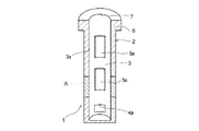
この実施例の連続鋳造用ノズル1は、ノズル本体2と、ノズル本体2内に設けられ溶鋼が流通するためのノズル内孔3と、ノズル本体2の下部に対向して設けられた一対の吐出口4a,4bとを有し、ノズル内孔3は、一対の吐出口4a,4bの上部に対向して設けられ、メニスカスAの上下に渡って連続した一対の段差5a,5bを有している。以下、各構成について順次詳述する。
The continuous casting nozzle of the present invention will be described with reference to one embodiment shown in FIG. 1 or FIG.
The continuous casting nozzle 1 of this embodiment includes a
ノズル本体2は、黒鉛等や有機樹脂等の炭素含有原料と様々な酸化物を組み合わせて形成した耐火物により構成されており、略円筒体で、その上部には拡径した首部6が一体成形されている。
The
ノズル本体2内には、溶鋼が流れるノズル内孔3がノズル本体2の上端から最下部に渡って形成されている。ノズル内孔3は、上部において上端開口7に連通しており、下部においては吐出口4a,4bに連通している。
In the
吐出口4a,4bはモールド内に溶鋼を流入させる開口であり、ノズル本体2の径方向に対向して(ノズル本体の中心軸に対して対称の位置に)設けられている。
The
ノズル内孔3は、一対の吐出口4a,4bの上部に対向して(ノズル本体の中心軸に対して対称の位置に)設けられ、メニスカスAの上下に渡って連続した一対の段差5a,5bを有している。メニスカスの上下に渡ってこのような段差5a,5bが設けられることにより、メニスカス付近の溶鋼が、吐出口側ではノズル内孔3を縮径する段差5a,5bの表面に沿ってモールド内に誘導され、他方、段差が設けられていない反吐出口側ではノズル内孔3の内面3aに沿ってモールド内に流入するため、環状段差が設けられた場合に比して溶鋼の流入速度が緩和されると共に、段差5a,5bは対向した位置に(ノズル本体の中心軸に対して対称の位置に)設けられているため、左右の吐出口からの吐出量も均一化され、うねり等に起因した湯面変動がより少ない連続鋳造用浸漬ノズルが構成される。特に、本発明では、一対の段差5a,5bがメニスカスの上下に渡って連続的に設けられているため、吐出口側では、溶鋼をノズル本体2の中央に効果的に誘導することができ偏流をより抑制できる。
The nozzle
なお、一対の段差5a,5bの上下端部は、それぞれノズル内孔3の内孔面に向かってテーパー面に形成されていることが好ましく、これにより、溶損および溶鋼の飛散がより少ない段差を構成できる。
Note that the upper and lower ends of the pair of
段差5a,5bはそれぞれ、ノズル内孔3の内周において45〜135°の範囲内にそれぞれ形成されていることが好ましい。45°未満であると、段差として小さすぎて偏流抑止とならないためであり、135°を越えると大きすぎて環状段差と変わらなくなって溶鋼の流速が速くなり過ぎて湯面変動が頻繁に生じるようになるからである。なお、この実施例の段差5a,5bはそれぞれ、ノズル内孔3の内周の90°の範囲に渡って設けられている。
The
また、段差5a,5bはそれぞれ、厚みが5〜15mmの範囲内に形成されていることが好ましい。5mm未満であると、段差として低くすぎて偏流抑止とならないためであり、15mmを越えると高すぎて溶鋼の流速が速くなり湯面変動が頻繁に発生するようになるからである。なお、この実施例の段差5a,5bはそれぞれ、厚み10mmに形成されている。
Moreover, it is preferable that each of the
さらに、段差5a,5bはそれぞれ、上下方向の長さが80〜250mmの範囲内に形成されていることが好ましい。80未満であると、段差として短すぎて偏流抑止とならないためであり、250mmを越えると長すぎて内径を絞ったものと変わらなくなると共に溶鋼の流速が速くなり過ぎて湯面変動が頻繁に発生するようになるからである。なお、この実施例の段差5a,5bはそれぞれ、上下方向の長さが170mmに形成されている。
Furthermore, it is preferable that each of the
さらに、段差5a,5bの下端は吐出口4a,4bの上端より100mm以上離間していることが好ましい。100mm未満であると、段差5a,5bによって誘導された溶鋼の下向きの流れが直接吐出口付近に影響し、良好な吐出を阻害するからである。
Furthermore, it is preferable that the lower ends of the
ノズル内孔3の一対の段差5a,5bの上部には、対向して設けられた(ノズル本体の中心軸に対して対称の位置に)一対の第2段差8a,8bが形成されている。この実施例では、段差5a,5bの上部に設けられた第2段差も、環状段差ではなく、吐出口側のみに形成されている。これにより、溶鋼の流速がより緩和される。
A pair of
なお、一対の第2段差8a,8bの上下端部も、それぞれノズル内孔3の内孔面に向かってテーパー面に形成されていることが好ましく、これにより、溶損および溶鋼の飛散がより少ない段差を構成できる。
In addition, it is preferable that the upper and lower ends of the pair of
第2段差8a,8bはそれぞれ、ノズル内孔3の内周において45〜135°の範囲内にそれぞれ形成されていることが好ましい。45°未満であると、段差として小さすぎて偏流抑止とならないためであり、135°を越えると大きすぎて環状段差と変わらなくなって溶鋼の流速が速くなり過ぎて湯面変動が頻繁に発生するようになるからである。なお、この実施例の第2段差8a,8bはそれぞれ、ノズル内孔3の内周の90°の範囲に渡って設けられている。
Each of the
また、第2段差8a,8bはそれぞれ、厚みが5〜15mmの範囲内に形成されていることが好ましい。5mm未満であると、段差として低くすぎて偏流抑止とならないためであり、15mmを越えると高すぎて溶鋼の流速が速くなり湯面変動が頻繁に発生するようになるからである。なお、この実施例の第2段差8a,8bはそれぞれ、厚み10mmに形成されている。
Moreover, it is preferable that the
さらに、第2段差8a,8bはそれぞれ、上下方向の長さが80〜250mmの範囲内に形成されていることが好ましい。80未満であると、段差として短すぎて偏流抑止とならないためであり、250mmを越えると長すぎて内径を絞ったものと変わらなくなると共に溶鋼の流速が速くなり湯面変動が頻繁に発生するようになるからである。なお、この実施例の段差8a,8bはそれぞれ、上下方向の長さが100mmに形成されている。
Furthermore, it is preferable that the
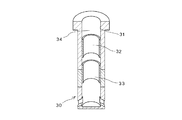
つぎに、図3および図4に示した本発明の他の実施例について説明する。
この実施例の連続鋳造用浸漬ノズル10と連続鋳造用浸漬ノズル1との相違は、
連続鋳造用浸漬ノズル10の第2段差18が環状段差である点のみであり、他は連続鋳造用浸漬ノズル1と同様である。連続鋳造用浸漬ノズル1と同一構成部分について同一符号を付し説明を省略する。
Next, another embodiment of the present invention shown in FIGS. 3 and 4 will be described.
The difference between the continuous
The only difference is that the
この実施例の第2段差18は、厚み10mm、上下方向の長さ100mmに形成された環状段差である。溶鋼の偏流は上部の方が大きいため、この実施例のように、第2段差を環状とすることにより、溶鋼の流速は速くなるが初期偏流を効果的に抑止できる。このように、第2段差が環状段差であるものも本発明の範疇に包含される。
The
(湯面変動試験)
以下の実施例および比較例の連続鋳造用浸漬ノズルN(n1,n2,n3,n4,n5,n6)を、図5に示すように、モールドサイズ2000×200mmのモールド50内に深さ(浸漬した連続鋳造用浸漬ノズルNの吐出口上端から基準線Lまでの距離)200mm浸漬し、流速2.0/min.で連続鋳造用浸漬ノズルN(n1,n2,n3,n4,n5,n6)の上端開口から水をそれぞれ流入して湯面変動を観察した。具体的には、湯面変動の様子をカメラ60で撮影して観察すると共に、基準線Lからの最大変位(変動高さ)を計測して、連続鋳造用浸漬ノズルN(n1,n2,n3,n4,n5,n6)の湯面変動を数値化した。
(Water level fluctuation test)
The immersion nozzles N (n1, n2, n3, n4, n5, n6) for continuous casting of the following examples and comparative examples are depth (immersion) in a
実施例1(n1)として、筒状体の高さ1000mm、外径130mm、内径80mmで、下部の対向する部位に一対の吐出口を設けると共に、それぞれの吐出口上端より100mm上方(段差位置)に上下方向の長さ(段差長さ)150mm、厚さ10mmの段差を内周の90゜に渡って一体成形した連続鋳造用浸漬ノズルを作製した。この連続鋳造用浸漬ノズルn1は、メニスカス(この試験では基準線L)の上下に渡って連続的に設けられた部分段差を有している。 As Example 1 (n1), the cylindrical body has a height of 1000 mm, an outer diameter of 130 mm, and an inner diameter of 80 mm, and a pair of discharge ports are provided at the lower opposing portions, and 100 mm above each discharge port upper end (step position). A continuous casting immersion nozzle was prepared by integrally forming a step having a length of 150 mm in the vertical direction (step length) and a thickness of 10 mm over 90 ° of the inner periphery. This continuous casting immersion nozzle n1 has partial steps provided continuously above and below the meniscus (reference line L in this test).
実施例2(n2)として、実施例1と同一寸法で一対の吐出口を備えた筒状体において、それぞれの吐出口上端より150mm上方(段差位置)に上下方向の長さ(段差長さ)150mm、厚さ10mmの段差を内周の90゜に渡って一体成形した連続鋳造用浸漬ノズルを作製した。この連続鋳造用浸漬ノズルn2も、メニスカス(この試験では基準線L)の上下に渡って連続的に設けられた部分段差を有している。 As Example 2 (n2), in a cylindrical body having the same dimensions as in Example 1 and provided with a pair of discharge ports, the length in the vertical direction (step height) 150 mm above (upper step position) from the upper end of each discharge port. An immersion nozzle for continuous casting in which a step having a thickness of 150 mm and a thickness of 10 mm was integrally formed over 90 ° of the inner periphery was produced. The continuous casting immersion nozzle n2 also has partial steps provided continuously above and below the meniscus (the reference line L in this test).
比較例1(n3)として、実施例1と同一寸法で一対の吐出口を備えた筒状体において、吐出口上端より100mm上方(段差位置)に上下方向の長さ(段差長さ)150mm、厚さ10mmの環状段差を一体成形した連続鋳造用浸漬ノズルを作製した。 As Comparative Example 1 (n3), in a cylindrical body having the same dimensions as in Example 1 and provided with a pair of discharge ports, the vertical length (step length) is 150 mm, 100 mm above (step position) from the upper end of the discharge port, An immersion nozzle for continuous casting in which an annular step having a thickness of 10 mm was integrally formed was produced.
比較例2(n4)として、実施例1と同一寸法で一対の吐出口を備えた筒状体において、段差を形成しない連続鋳造用浸漬ノズルを作製した。 As Comparative Example 2 (n4), an immersion nozzle for continuous casting was produced in which a step was not formed in a cylindrical body having the same dimensions as Example 1 and having a pair of discharge ports.
比較例3(n5)として、図6に示すように、実施例1と同一寸法で一対の吐出口71を備えた筒状体において、吐出口71の上端より30mm上方(段差位置)に上下方向の長さ(段差長さ)150mm、厚さ10mmの段差72を内周の90゜に渡って一体成形した連続鋳造用浸漬ノズルを作製した。この連続鋳造用浸漬ノズルn5は、メニスカス(この試験では基準線L)の下方に段差72を有している。
As Comparative Example 3 (n5), as shown in FIG. 6, in a cylindrical body having the same dimensions as in Example 1 and having a pair of
比較例4(n6)として、図6に示すように、実施例1と同一寸法で一対の吐出口71を備えた筒状体において、吐出口71の上端より250mm上方(段差位置)に上下方向の長さ(段差長さ)150mm、厚さ10mmの段差73を内周の90゜に渡って一体成形した連続鋳造用浸漬ノズルを作製した。この連続鋳造用浸漬ノズルn6は、メニスカス(この試験では基準線L)の上方に段差73を有している。
As Comparative Example 4 (n6), as shown in FIG. 6, in a cylindrical body having the same dimensions as in Example 1 and having a pair of
このような湯面変動試験の結果、以下の表1に示すように、比較例1ないし比較例4の連続鋳造用浸漬ノズルn3,n4,n5,n6ではうねりが多いまたは非常に多いのに対して、実施例1および実施例2の連続鋳造用浸漬ノズルn1,n2では比較的うねりが少なかった。変動高さも比較例1ないし比較例4では30〜35mmであるのに対して、実施例の1および実施例2では25mmと小さくなった。 As a result of the molten metal surface fluctuation test, as shown in Table 1 below, the continuous casting immersion nozzles n3, n4, n5, and n6 of Comparative Examples 1 to 4 have much undulation or very much. In the continuous casting immersion nozzles n1 and n2 of Example 1 and Example 2, there was relatively little waviness. The fluctuation height was 30 to 35 mm in Comparative Examples 1 to 4, whereas it was as small as 25 mm in Example 1 and Example 2.
また、メニスカス(この試験では基準線L)の下方に段差72を設けた比較例3の連続鋳造用浸漬ノズルn5は、吐出口71の上部に段差72によって誘導した溶鋼の流速がそのまま吐出流に影響するため湯面変動が大きくなった。さらに、メニスカス(この試験では基準線L)の上方に段差73を設けた比較例4の連続鋳造用浸漬ノズルn6は、段差73で中央に誘導された溶鋼が湯面に直接落下するため湯面変動が大きくなった。
Further, in the immersion nozzle n5 for continuous casting of Comparative Example 3 in which the
これらの結果より、メニスカスの上下に渡って連続的に設けられた部分段差を有した連続鋳造用浸漬ノズルn1,n2では、湯面変動が少なく、かつ小さくなることが確認された。 From these results, it was confirmed that the continuous casting immersion nozzles n1 and n2 having partial steps provided continuously over the upper and lower sides of the meniscus are small and small in molten metal surface level.

1 連続鋳造用浸漬ノズル
2 ノズル本体
3 ノズル内孔
4a,4b 吐出口
5a,5b 段差
6 首部
7 上端開口
8a,8b 第2段差
DESCRIPTION OF SYMBOLS 1 Submerged nozzle for
Claims (3)
該ノズル本体内に設けられ溶鋼が流通するためのノズル内孔と、
前記ノズル本体の下部に対向して対称に設けられた一対の吐出口とを有し、
前記ノズル内孔は、前記一対の吐出口の上部に対向して対称に設けられ、メニスカスの上下に渡って80〜250mmの範囲内で連続した一対の段差を有し、反吐出口側には段差が設けられていないことを特徴とする連続鋳造用浸漬ノズル。 A nozzle body;
A nozzle bore provided in the nozzle body for flowing molten steel;
A pair of discharge ports provided symmetrically facing the lower portion of the nozzle body,
The nozzle inner holes are provided symmetrically facing the upper portions of the pair of discharge ports, and have a pair of steps that are continuous within a range of 80 to 250 mm across the upper and lower sides of the meniscus, and a step on the side opposite to the discharge ports A continuous casting immersion nozzle characterized in that is not provided .
Priority Applications (1)
| Application Number | Priority Date | Filing Date | Title |
|---|---|---|---|
| JP2011035329A JP5366991B2 (en) | 2011-02-22 | 2011-02-22 | Immersion nozzle for continuous casting |
Applications Claiming Priority (1)
| Application Number | Priority Date | Filing Date | Title |
|---|---|---|---|
| JP2011035329A JP5366991B2 (en) | 2011-02-22 | 2011-02-22 | Immersion nozzle for continuous casting |
Publications (2)
| Publication Number | Publication Date |
|---|---|
| JP2012170981A JP2012170981A (en) | 2012-09-10 |
| JP5366991B2 true JP5366991B2 (en) | 2013-12-11 |
Family
ID=46974380
Family Applications (1)
| Application Number | Title | Priority Date | Filing Date |
|---|---|---|---|
| JP2011035329A Expired - Fee Related JP5366991B2 (en) | 2011-02-22 | 2011-02-22 | Immersion nozzle for continuous casting |
Country Status (1)
| Country | Link |
|---|---|
| JP (1) | JP5366991B2 (en) |
Family Cites Families (2)
| Publication number | Priority date | Publication date | Assignee | Title |
|---|---|---|---|---|
| JP2004283857A (en) * | 2003-03-20 | 2004-10-14 | Shinagawa Refract Co Ltd | Nozzle for continuously casting steel |
| JP4434826B2 (en) * | 2004-04-28 | 2010-03-17 | 品川リフラクトリーズ株式会社 | Immersion nozzle for continuous casting of steel |
-
2011
- 2011-02-22 JP JP2011035329A patent/JP5366991B2/en not_active Expired - Fee Related
Also Published As
| Publication number | Publication date |
|---|---|
| JP2012170981A (en) | 2012-09-10 |
Similar Documents
| Publication | Publication Date | Title |
|---|---|---|
| JP5451868B2 (en) | Immersion nozzle for continuous casting equipment | |
| TWI451923B (en) | Immersion nozzle | |
| KR101170673B1 (en) | Immersion nozzle for casting and continuous casting apparatus including the same | |
| JP5047854B2 (en) | Immersion nozzle for continuous casting | |
| JP5366991B2 (en) | Immersion nozzle for continuous casting | |
| AU2007329897B2 (en) | Molten metal continuous casting method | |
| CN108025352B (en) | Immersion nozzle | |
| US11052459B2 (en) | Submerged entry nozzle for continuous casting | |
| JP4833744B2 (en) | Immersion nozzle | |
| JPWO2017030052A1 (en) | Annular weir | |
| KR20190090829A (en) | Sliding nozzle | |
| JP4578555B2 (en) | Immersion nozzle for continuous casting | |
| EP2111316B1 (en) | A submerged entry nozzle | |
| RU2016128990A (en) | CRYSTALIZER FOR CASTING OF STEEL MELT | |
| WO2023190017A1 (en) | Immersion nozzle, mold, and steel continuous casting method | |
| CN113226594B (en) | Immersion nozzle | |
| KR101221466B1 (en) | Immersion nozzle for casting and continuous casting apparatus including the same | |
| JP5673162B2 (en) | Continuous casting method and continuous casting apparatus | |
| JP2020059036A (en) | Continuous casting method for slab | |
| JP5239554B2 (en) | Immersion nozzle for continuous casting of slabs | |
| JP4750013B2 (en) | Immersion nozzle with drum type weir | |
| JP6135708B2 (en) | Immersion nozzle for continuous casting and continuous casting method using the immersion nozzle | |
| JP6551161B2 (en) | Pouring nozzle for twin roll casting apparatus, twin roll casting apparatus, and cast piece casting method | |
| KR20150117448A (en) | Mould for continuous casting of billet | |
| JP2008030089A (en) | Immersion nozzle for continuously casting molten steel and continuous casting method |
Legal Events
| Date | Code | Title | Description |
|---|---|---|---|
| A977 | Report on retrieval |
Free format text: JAPANESE INTERMEDIATE CODE: A971007 Effective date: 20121226 |
|
| A131 | Notification of reasons for refusal |
Free format text: JAPANESE INTERMEDIATE CODE: A131 Effective date: 20130613 |
|
| A521 | Written amendment |
Free format text: JAPANESE INTERMEDIATE CODE: A523 Effective date: 20130812 |
|
| TRDD | Decision of grant or rejection written | ||
| A01 | Written decision to grant a patent or to grant a registration (utility model) |
Free format text: JAPANESE INTERMEDIATE CODE: A01 Effective date: 20130828 |
|
| A61 | First payment of annual fees (during grant procedure) |
Free format text: JAPANESE INTERMEDIATE CODE: A61 Effective date: 20130910 |
|
| R150 | Certificate of patent or registration of utility model |
Free format text: JAPANESE INTERMEDIATE CODE: R150 |
|
| LAPS | Cancellation because of no payment of annual fees |