JP5366335B2 - Cleaning appliance - Google Patents
Cleaning appliance Download PDFInfo
- Publication number
- JP5366335B2 JP5366335B2 JP2011216491A JP2011216491A JP5366335B2 JP 5366335 B2 JP5366335 B2 JP 5366335B2 JP 2011216491 A JP2011216491 A JP 2011216491A JP 2011216491 A JP2011216491 A JP 2011216491A JP 5366335 B2 JP5366335 B2 JP 5366335B2
- Authority
- JP
- Japan
- Prior art keywords
- duct
- separation device
- cleaning appliance
- rolling assembly
- chassis
- Prior art date
- Legal status (The legal status is an assumption and is not a legal conclusion. Google has not performed a legal analysis and makes no representation as to the accuracy of the status listed.)
- Expired - Fee Related
Links
Images


Classifications
-
- A—HUMAN NECESSITIES
- A47—FURNITURE; DOMESTIC ARTICLES OR APPLIANCES; COFFEE MILLS; SPICE MILLS; SUCTION CLEANERS IN GENERAL
- A47L—DOMESTIC WASHING OR CLEANING; SUCTION CLEANERS IN GENERAL
- A47L5/00—Structural features of suction cleaners
- A47L5/12—Structural features of suction cleaners with power-driven air-pumps or air-compressors, e.g. driven by motor vehicle engine vacuum
- A47L5/22—Structural features of suction cleaners with power-driven air-pumps or air-compressors, e.g. driven by motor vehicle engine vacuum with rotary fans
- A47L5/36—Suction cleaners with hose between nozzle and casing; Suction cleaners for fixing on staircases; Suction cleaners for carrying on the back
- A47L5/362—Suction cleaners with hose between nozzle and casing; Suction cleaners for fixing on staircases; Suction cleaners for carrying on the back of the horizontal type, e.g. canister or sledge type
-
- A—HUMAN NECESSITIES
- A47—FURNITURE; DOMESTIC ARTICLES OR APPLIANCES; COFFEE MILLS; SPICE MILLS; SUCTION CLEANERS IN GENERAL
- A47L—DOMESTIC WASHING OR CLEANING; SUCTION CLEANERS IN GENERAL
- A47L9/00—Details or accessories of suction cleaners, e.g. mechanical means for controlling the suction or for effecting pulsating action; Storing devices specially adapted to suction cleaners or parts thereof; Carrying-vehicles specially adapted for suction cleaners
- A47L9/009—Carrying-vehicles; Arrangements of trollies or wheels; Means for avoiding mechanical obstacles
-
- A—HUMAN NECESSITIES
- A47—FURNITURE; DOMESTIC ARTICLES OR APPLIANCES; COFFEE MILLS; SPICE MILLS; SUCTION CLEANERS IN GENERAL
- A47L—DOMESTIC WASHING OR CLEANING; SUCTION CLEANERS IN GENERAL
- A47L9/00—Details or accessories of suction cleaners, e.g. mechanical means for controlling the suction or for effecting pulsating action; Storing devices specially adapted to suction cleaners or parts thereof; Carrying-vehicles specially adapted for suction cleaners
- A47L9/24—Hoses or pipes; Hose or pipe couplings
Abstract
Description
本発明は、1つの実施形態では真空掃除用電気器具の形態である掃除用電気器具に関する。 The present invention relates to a cleaning appliance, which in one embodiment is in the form of a vacuum cleaning appliance.
真空掃除機のような掃除用電気器具は公知である。真空掃除機の大部分は、「直立」型又は「円筒」型(国によってはキャニスタ又はバレル機と呼ばれる)の何れかである。円筒真空掃除機は、一般的に、汚れを含む空気流を真空掃除機に引き込むためのモータ駆動ファンユニットを収容する本体と、空気流から汚れ及び塵埃を分離するためのサイクロン分離器又はバッグのような分離装置とを含む。汚れを含む空気流は、本体に接続される吸引ホース及びワンド組立体を通って本体に導入される。真空掃除機の本体は、ユーザが部屋を動き回るとホースによって引きずられる。掃除ツールは、ホース及びワンド組立体の遠位端部に取り付けられる。 Cleaning appliances such as vacuum cleaners are known. Most vacuum cleaners are either “upright” or “cylindrical” (sometimes called canisters or barrel machines in some countries). Cylindrical vacuum cleaners generally include a body that houses a motor driven fan unit for drawing an air stream containing dirt into the vacuum cleaner, and a cyclone separator or bag for separating dirt and dust from the air stream. And such a separation device. The air stream containing dirt is introduced into the body through a suction hose and wand assembly connected to the body. The body of the vacuum cleaner is dragged by a hose as the user moves around the room. The cleaning tool is attached to the distal end of the hose and wand assembly.
例えば、英国特許第2,407,022号は、サイクロン分離装置を支持するシャーシを有する円筒真空掃除機を記載している。真空掃除機は、シャーシの後部の両側に1つずつ2つのメインホイールと、シャーシの前部の下に位置し、表面を横切って真空掃除機を引きずることを可能にするキャスタホイールとを有する。このようなキャスタホイールは、円形支持体に取付けられていることが多く、該円形支持体は、真空掃除機が表面にわたって引きずられる方向の変化に応答してキャスタホイールが旋回できるように、シャーシに回転可能に取付けられている。 For example, British Patent 2,407,022 describes a cylindrical vacuum cleaner having a chassis that supports a cyclone separator. The vacuum cleaner has two main wheels, one on each side of the rear of the chassis, and a caster wheel located below the front of the chassis and allowing the vacuum cleaner to be dragged across the surface. Such caster wheels are often attached to a circular support, which is attached to the chassis so that the caster wheel can pivot in response to changes in the direction in which the vacuum cleaner is dragged across the surface. It is mounted rotatably.
欧州特許第1,129,657号は、吸引ホース及びワンド組立体に接続された球状体の形態である円筒真空掃除機を記載している。球状体の球状容積は、本体の両側に1つずつ位置する1対のホイールと、掃除機を通って流体流を引き込むための電気送風機と、汚れ及び塵埃を流体流から分離するための塵埃バッグとを組み込んでいる。 EP 1,129,657 describes a cylindrical vacuum cleaner in the form of a sphere connected to a suction hose and wand assembly. The spherical volume of the sphere includes a pair of wheels, one on each side of the body, an electric blower for drawing fluid flow through the cleaner, and a dust bag for separating dirt and dust from the fluid flow. And is incorporated.
PCT/GB2010/050418号は、床面にわたる真空掃除機の操縦性を改良するためにシャーシに接続されたほぼ球状の転動組立体を有する円筒真空掃除機を記載している。転動組立体は、本体及び本体に接続された1対のドーム形ホイールを含む。シャーシは、転動組立体の本体から前方に延びて、真空掃除機を操向するため及び真空掃除機が床面にわたって操縦されるときに転動組立体を支持するための1対のホイールを含む。 PCT / GB2010 / 050418 describes a cylindrical vacuum cleaner having a generally spherical rolling assembly connected to the chassis to improve the maneuverability of the vacuum cleaner across the floor. The rolling assembly includes a body and a pair of dome-shaped wheels connected to the body. The chassis extends forward from the body of the rolling assembly and includes a pair of wheels for steering the vacuum cleaner and for supporting the rolling assembly when the vacuum cleaner is maneuvered across the floor. Including.
シャーシはまた、真空掃除機のサイクロン分離装置を支持する支持体を含む。支持体は、汚れを含む空気流を分離装置に搬送するための入口ダクト上に位置する。床面上に位置する物体の周囲の真空掃除機の操縦を支援するために、ユーザが床面にわたって異なる方向に真空掃除機を引っ張ったときにシャーシに対して動くように、入口ダクトはシャーシに枢動可能に接続されている。シャーシに対するダクトの動きは、シャーシに接続されたホイールを転回させるための操向機構を作動させる。入口ダクトは、相対的に枢動運動するためにシャーシに接続された比較的剛直な部分と、剛直な部分の上流に位置して、シャーシに対してダクトが枢動すると剛直な部分に対して屈曲する傾向がある比較的可撓性のホースとを含む。 The chassis also includes a support that supports the cyclonic separator of the vacuum cleaner. The support is located on the inlet duct for conveying the air stream containing dirt to the separation device. In order to assist in maneuvering the vacuum cleaner around an object located on the floor, the inlet duct is connected to the chassis so that it moves relative to the chassis when the user pulls the vacuum cleaner in different directions across the floor. It is pivotally connected. The movement of the duct relative to the chassis activates a steering mechanism for turning the wheel connected to the chassis. The inlet duct is positioned relatively upstream of the rigid portion connected to the chassis for relative pivoting movement, and relative to the rigid portion as the duct pivots relative to the chassis. And relatively flexible hoses that tend to bend.
本発明は、汚れ含有流体流から汚れを分離するための分離装置と、分離装置を通って流体流を引き込む手段を含む床係合転動組立体と、転動組立体に接続されたシャーシと、流体流を分離装置に搬送するため転動組立体に解放可能に接続される出口部分と、出口部分及びシャーシに対して枢動運動するためシャーシに接続された入口部分と、を含むダクトと、を備える、円筒型の掃除用電気器具を提供する。 The present invention includes a separation device for separating soil from a soil-containing fluid stream, a floor engagement rolling assembly including means for drawing a fluid stream through the separation device, and a chassis connected to the rolling assembly. A duct comprising: an outlet portion releasably connected to the rolling assembly for conveying a fluid stream to the separation device; and an inlet portion connected to the chassis for pivoting relative to the outlet portion and the chassis; A cylindrical cleaning appliance is provided.
ダクトの取り外し可能な出口部分を設けることにより、何らかの妨害物をダクトの出口部分から容易に取り除くことが可能になり、更に、入口部分からの妨害物の取りのぞきが容易になる。出口部分が転動組立体に解除可能に接続されるようにダクトの形状を成形することで、小型の外観を有する掃除用電気器具を提供することができる。 By providing a removable outlet portion of the duct, any obstruction can be easily removed from the outlet portion of the duct, and further, removal of the obstruction from the inlet portion is facilitated. By forming the shape of the duct so that the outlet portion is releasably connected to the rolling assembly, a cleaning appliance having a compact appearance can be provided.
転動組立体は、好ましくは、シャーシに接続された本体と、複数の床係合転動要素とを含む。掃除用電気器具の構成要素の数を低減するために、シャーシは、好ましくは、転動組立体の本体の一部と一体化される。好ましくは、本体及び複数の床係合転動要素は共に、実質的に球状の床係合転動組立体を形成し、この用語は回転楕円状の転動組立体を含む。本体は、複数の部分を含むことができ、各転動要素は、部分のそれぞれの1つに接続することができる。シャーシは、好ましくは、本体の部分の1つと一体化される。ダクトの出口部分は、好ましくは、転動組立体の本体を解除可能似係合する手動操作可能なキャッチを含む。 The rolling assembly preferably includes a body connected to the chassis and a plurality of floor engaging rolling elements. In order to reduce the number of components of the cleaning appliance, the chassis is preferably integrated with a part of the body of the rolling assembly. Preferably, the body and the plurality of floor engaging rolling elements together form a substantially spherical floor engaging rolling assembly, which term includes a spheroid rolling assembly. The body can include a plurality of portions, and each rolling element can be connected to a respective one of the portions. The chassis is preferably integrated with one of the parts of the body. The outlet portion of the duct preferably includes a manually operable catch that releasably engages the body of the rolling assembly.
複数の転動要素の各々は、転動組立体の本体のそれぞれの側面に回転可能に接続されたホイールの形態であるのが好ましい。これらの転動要素の各々は、好ましくは湾曲した、好ましくはドーム形の外面を有する。複数の転動要素の各々は、好ましくは、実質的に球状の曲率の外面を有する。転動要素の回転軸線は、転動要素のリムが床面と係合するように掃除用電気器具が位置する床面に対して本体に向かって上向きに傾斜することができる。回転軸線の傾斜角度は、好ましくは4°から15°の範囲内、より好ましくは5°から10°の範囲内である。転動要素の回転軸線の傾斜の結果として、本体の外面の一部は、モータ又はケーブル巻き戻し機構を作動させるためのユーザ操作可能スイッチのような掃除用電気器具の構成要素を本体の露出部分上に位置付けることを可能にするように露出される。好ましい実施形態では、掃除用電気器具から空気流を排出するための1つ又はそれ以上のポートは、本体の外面上に位置する。 Each of the plurality of rolling elements is preferably in the form of a wheel rotatably connected to a respective side of the body of the rolling assembly. Each of these rolling elements preferably has a curved, preferably domed outer surface. Each of the plurality of rolling elements preferably has a substantially spherical curvature outer surface. The axis of rotation of the rolling element can be tilted upward toward the body relative to the floor surface on which the cleaning appliance is located such that the rim of the rolling element engages the floor surface. The inclination angle of the rotation axis is preferably in the range of 4 ° to 15 °, more preferably in the range of 5 ° to 10 °. As a result of the tilt of the rolling element's axis of rotation, a portion of the outer surface of the body may cause a component of a cleaning appliance such as a user operable switch to operate a motor or cable unwinding mechanism to be exposed Exposed to allow positioning on top. In a preferred embodiment, one or more ports for exhausting airflow from the cleaning appliance are located on the outer surface of the body.
分離装置は、好ましくは、サイクロン分離装置を含む。電気器具は、好ましくは、分離装置を支持する支持体を含む。支持体は、好ましくは分離装置の一部に接続され、より好ましくは分離装置の一部と一体化される。支持体は、好ましくは、本体の前方上に位置付けられる。支持体は、好ましくは、分離装置の基部部材に形成された凹部内に位置決め可能な差込口を含む。分離装置が支持体上に装備されるときには、分離装置は、好ましくは、掃除用電気器具が実質的に水平な床面にわたって移動するときに垂直方向に対して鋭角に傾斜している長手方向軸線を有する。この角度は30°から70°の範囲内である。本体は更に、分離装置の側面を支持するための1つ又はそれ以上の追加の支持体を含むことができる。分離装置の側面は、好ましくは傾斜しており、よって、これらの追加の支持体は、好ましくは、分離装置の側面と類似の曲率を有する支持面を有する。ダクトの出口部分は、好ましくは、空気が通過する方向を変化させるような形状にされる。好ましい実施形態において、分離装置の流体入口は、分離装置の側面上に位置付けられ、よって、出口部分は、好ましくは、空気が通過する方向を20°から60°の範囲の角度だけ変化させるよう配置される。 The separation device preferably comprises a cyclone separation device. The appliance preferably includes a support that supports the separation device. The support is preferably connected to a part of the separation device, more preferably integrated with a part of the separation device. The support is preferably positioned on the front of the body. The support preferably includes a slot that can be positioned in a recess formed in the base member of the separation device. When the separation device is mounted on a support, the separation device is preferably a longitudinal axis that is inclined at an acute angle relative to the vertical direction when the cleaning appliance moves over a substantially horizontal floor surface. Have This angle is in the range of 30 ° to 70 °. The body can further include one or more additional supports for supporting the sides of the separation device. The sides of the separation device are preferably inclined, so that these additional supports preferably have a support surface with a curvature similar to that of the side of the separation device. The outlet portion of the duct is preferably shaped to change the direction in which air passes. In a preferred embodiment, the fluid inlet of the separation device is positioned on the side of the separation device, so the outlet portion is preferably arranged to change the direction in which the air passes by an angle in the range of 20 ° to 60 °. Is done.
ダクトの入口部分は、好ましくは、支持体の下方に延びる。ダクトは、好ましくは、転動組立体の支持体と本体との間に位置付けられるスリーブを通過する。スリーブは、好ましくは、支持体及び本体と一体化される。或いは、スリーブは、シャーシに接続することができる。スリーブは、好ましくは、ダクトの入口部分及び出口部分間の継手の周りに延びる。この継手は、入口部分が出口部分に対して枢動するときに、ダクトの部分間に流体密閉シールを維持するための1つ又はそれ以上のシール部材を含むことができる。支持体は、入口部分に対する出口部分の枢動運動を抑制する手段を含むことができる。例えば、支持体及び出口部分の一方は、支持体及び出口部分の他方の凹部内に位置付けることが可能な戻り止めを含むことができる。 The inlet portion of the duct preferably extends below the support. The duct preferably passes through a sleeve positioned between the support and body of the rolling assembly. The sleeve is preferably integral with the support and the body. Alternatively, the sleeve can be connected to the chassis. The sleeve preferably extends around a joint between the inlet and outlet portions of the duct. The joint may include one or more seal members for maintaining a fluid tight seal between the portions of the duct as the inlet portion pivots relative to the outlet portion. The support can include means for inhibiting pivoting movement of the outlet portion relative to the inlet portion. For example, one of the support and the outlet portion can include a detent that can be positioned in the other recess of the support and the outlet portion.
シャーシは、好ましくは、転動組立体が床面にわたって操縦されるときに該転動組立体を支持する複数の床係合支持部材を含む。各支持部材は、好ましくは、ホイール、或いはキャスター又はボールなどの他の転動部材の形態である。 The chassis preferably includes a plurality of floor engaging support members that support the rolling assembly as it is maneuvered across the floor surface. Each support member is preferably in the form of a wheel or other rolling member such as a caster or ball.
掃除用電気器具は、好ましくは、流体流を転動組立体に搬送するために分離装置から転動組立体に延びる出口ダクトを含む。好ましくは、ダクトは、分離装置を電気器具から取り外すことを可能にするように分離装置から係合解除することができる。分離装置からのダクトの係合解除を容易にするために、ダクトは、転動組立体に枢動可能に接続される。ダクトは、好ましくは、分離装置が電気器具から取り外された後に電気器具上に移動できるようにする上昇位置と、ダクトが分離装置と係合する下降位置との間でダクトが移動することができるように、転動組立体の上面に接続される。この下降位置では、ダクトは、好ましくは、電気器具上に分離装置を保持するように構成される。ダクトは、好ましくは、剛性材料、好ましくはプラスチック材料から形成され、ハンドルを含むことができる。 The cleaning appliance preferably includes an outlet duct that extends from the separation device to the rolling assembly for conveying a fluid stream to the rolling assembly. Preferably, the duct can be disengaged from the separation device to allow the separation device to be removed from the appliance. In order to facilitate disengagement of the duct from the separating device, the duct is pivotally connected to the rolling assembly. The duct preferably allows the duct to move between a raised position that allows the separation device to move over the appliance after being removed from the appliance and a lowered position where the duct engages the separation device. Thus, it is connected to the upper surface of the rolling assembly. In this lowered position, the duct is preferably configured to hold the separation device on the appliance. The duct is preferably formed from a rigid material, preferably a plastic material, and may include a handle.
転動組立体は、好ましくは、流体入口から流体流を受け入れ、分離装置を通って流体流を引き込む手段に流体流を搬送する導管を含む。分離装置を通って流体流を引き込む手段は、好ましくは、モータ駆動ファンユニットの形態である。好ましい実施形態では、導管は、ダクトから流体流を受け取る流体入口と、分離装置を通って流体流を引き込む手段に流体流を搬送する流体出口とを含む。分離装置を通って流体流を引き込む手段の向きに応じて、導管は、流体流の方向を約90°変更するよう配置することができる。ダクトが分離装置から係合解除されたとき、或いは、出口ダクトが上昇位置にあるときに比較的大きな物体が分離装置のフィルタ組立体内に意図せずに位置付けられた場合に、汚れ又は他の物体が導管内に入るのを防ぐために出口ダクト内に格子又は他のフィルタを設けてもよい。 The rolling assembly preferably includes a conduit that receives the fluid stream from the fluid inlet and conveys the fluid stream to the means for drawing the fluid stream through the separation device. The means for drawing a fluid flow through the separation device is preferably in the form of a motor driven fan unit. In a preferred embodiment, the conduit includes a fluid inlet that receives the fluid stream from the duct and a fluid outlet that conveys the fluid stream to the means for drawing the fluid stream through the separator. Depending on the orientation of the means for drawing the fluid flow through the separator, the conduit can be arranged to change the direction of the fluid flow by approximately 90 °. Dirt or other objects when the duct is disengaged from the separator or when a relatively large object is unintentionally positioned in the filter assembly of the separator when the outlet duct is in the raised position A grid or other filter may be provided in the outlet duct to prevent the water from entering the conduit.
本発明の実施形態は、真空掃除機を参照して詳細に説明したが、本発明はまた、掃除用電気器具の他の形態にも適用できることは理解されるであろう。 While embodiments of the present invention have been described in detail with reference to a vacuum cleaner, it will be understood that the present invention is also applicable to other forms of cleaning appliances.
次に、本発明の好ましい特徴を単に例として添付図面を参照しながら説明する。 The preferred features of the present invention will now be described by way of example only with reference to the accompanying drawings.
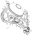
図1は、真空掃除機10の形態の掃除用電気器具の外観を示す。真空掃除機10は、円筒型又はキャニスタ型のものである。概説すると、真空掃除機10は、汚れ及び塵埃を流体流から分離するための分離装置12を含む。分離装置12は、好ましくは、サイクロン分離装置の形態であって、実質的に円筒形状の外壁16を有する外側容器14を含む。外側容器14の下側端部は、外壁16に枢動可能に取り付けられる湾曲基部18によって閉鎖している。汚れを含む流体を分離装置12に引き込むために吸引を発生させるためのモータ駆動ファンユニットは、分離装置12の背後に位置した転動組立体20内に収納される。転動組立体20は、本体22と、床面と係合するために本体22に回転可能に接続された2つのホイール24、26(図2(a)参照)とを含む。分離装置12の下方に延びる入口ダクト28は、汚れを含む流体を分離装置12に搬送し、出口ダクト30は、分離装置12から排出された流体を転動組立体20に搬送する。入口ダクト28は、ユーザが引っ張って床面にわたって真空掃除機10を操縦するホース及びワンド組立体(図示せず)のホースに接続される。
FIG. 1 shows the exterior of a cleaning appliance in the form of a
シャーシ32は、転動組立体20の本体22に接続される。この実施例では、シャーシ32は、転動組立体20の本体22の一部と一体化されている。シャーシ32は、全体的に転動組立体20から前方向きの矢じりの形状である。シャーシ32は、図5(b)及び6(a)に示すシャーシ32の前方先端36から後方及び外向きに延びる側縁34を含む。シャーシ32の前方先端36は、転動組立体20の中心を貫通する垂直平面に対して実質的に直角に延びる軸線A上に位置する。真空掃除機10が清掃作業中に床面にわたって移動する方向は、軸線Aに沿って延びる。軸線Aに対する側縁34の傾斜は、隅部、家具、又は床面から直立した他の品目の周囲で真空掃除機10を操縦するのを助けることができ、このような品目と接触した場合に、これらの側縁34は、直立する品目に接して滑動して転動組立体20を直立する品目の周囲に案内する傾向がある。図示のように、バンパー又はパッド38は、側縁34に取り付けることができる。
The
床面と係合するための1対のホイール40は、シャーシ32に接続される。ホイール40は、シャーシ32の側縁34の背後で且つ転動組立体20のホイール24、26の前方に位置する。図3に示すように、各ホイール40は、ホイール40が、軸線42に対して、及びひいてはシャーシ32に対して回転するように、例えば、圧入又はオーバーモールド成形によって、シャーシ32に合わせたそれぞれの軸線42に取付けられている。各軸線42は、ホイール40が回転して真空掃除機10を軸線Aに沿って延びる方向に移動させるように、軸線Aに対して実質的に直角である軸線に沿って整列している。
A pair of
ホイール40はまた、転動組立体20を支持するための支持部材を設け、真空掃除機10が軸線Aの周りで転動組立体20の回転を制限することによって床面にわたって操縦されるようにする。転動組立体20への支持を向上させるために、床面とホイール40の接点間の距離は、床面と転動組立体20のホイール24、26との接点間の距離よりも大きい。
The
図2(b)に示すように、真空掃除機10の構成要素は、真空掃除機10が実質的に水平な床面F上に位置するときに、真空掃除機10の重心Cが転動組立体20内に位置するように配置される。重心Cは、転動組立体20のホイール24、26と床面との間に接点を含む第2の垂直平面PL2と、ホイール40と床面との間に接点を含む第3の垂直平面PL3との間、好ましくは2つの平面PL2、PL3間の実質的に中間を通る第1の垂直平面PL1内に位置する。これは、真空掃除機10が床面にわたって操縦されるときの真空掃除機10の安定性を更に高めることができる。
As shown in FIG. 2B, when the
重心Cの位置は、分離装置12が真空掃除機10に接続され、分離装置12は無負荷状態でホース及びワンド組立体が真空掃除機10に接続されていない状態にある状況において、上記に示されている。
The position of the center of gravity C is shown above in the situation where the
真空掃除機10が床面にわたって移動している方向を反転するために、ユーザは、ホース及びワンド組立体のホースを用いてシャーシ32のホイール40を床面から引き上げて、真空掃除機10が転動組立体20のホイール24、26に対して後方に傾くようにすることができる。次に、ホースを用いて、真空掃除機10は、該真空掃除機10が必要とされる方向に面するまで、転動組立体20と床面との間の接点の周囲を「回転」することができる。次いで、ホースを下げて、ホイール40を床面と必要とされる方向に引っ張られた真空掃除機10とを接触状態にすることができる。
To reverse the direction in which the
清掃作業中に真空掃除機10を物体又は壁の隅部の周囲で滑らかに操縦できるようにするために、入口ダクト28の一部は、シャーシ32に対して、ひいては転動組立体20に対して枢動運動するようにシャーシ32に接続される。図2(a)から図2(c)は、入口ダクト28を明瞭にした、分離装置12を有する真空掃除機10を示す。真空掃除機10から分離装置12の取り外しについては、以下でより詳細に説明する。入口ダクト28は、ホース及びワンド組立体から汚れを含む流体流を受け入れるための入口部分44と、汚れを含む流体流を分離装置12に搬送するため入口部分44を分離装置12に結合する出口部分46とを含む。入口部分44は、シャーシ32に枢動可能に接続され、出口部分46は、入口部分44が出口部分46に対して枢動可能なように転動組立体20の本体22に接続される。或いは、出口部分46は、シャーシ32に接続されてもよい。
To allow the
特に図3、図4、図6(a)及び図6(b)を参照すると、この実施例では、入口ダクト28の入口部分44は、複数の構成要素を含む。入口部分44は、汚れを含む流体流を入口ダクト28に搬送するためにワンド及びホース組立体(図示せず)に対する電気的及び/又は物理的接続のためのカップリング48を含む。ワンド及びホース組立体は、汚れを含む流体流が通過して真空掃除機10に引き込まれる吸引開口部を含む掃除機ヘッド(図示せず)に接続される。カップリング48は、入口ダクト28の円筒部分50の一方の端部に接続される。勿論、部分50は、楕円形又は多面体形状のような代替の断面形状を有することができる。円筒部分50の他方の端部は、入口ダクト28の湾曲部分52に接続される。この実施例では、円筒部分50は、湾曲部分52と一体化されているが、入口ダクト28のこれらの2つの部分50、52は、一体的に形成してもよい。湾曲部分52は、流体が入口ダクト28を通過する方向を約90°変更するように成形される。湾曲部分52は、入口ダクト28の出口部分46の流体入口56と同心状に配置され且つ該入口56の下方に位置する流体出口54を有する。1つ又はそれ以上の環状シール部材58、60は、流体出口54と流体入口56との間に位置し、出口部分46に対する入口部分44の枢動運動中にこれらの間に気密シール及び比較的低い摩擦力を維持する。
With particular reference to FIGS. 3, 4, 6 (a) and 6 (b), in this embodiment, the
入口部分44は、シャーシ32の上面から上向きに延びる円筒スピンドル62に取付けられている。湾曲部分52は、そこから垂下する円筒ボス64を含み、該ボスは、スピンドル62と実質的に同心状であるようにスピンドル62の上に位置する。滑り軸受又はスリーブ66は、スピンドル62とボス64との間に位置し、スピンドル62の周りでのボス64の回転中にこれらの間の摩擦を最小限にして、スピンドル62とボス64との間の正確なアラインメントを保証することができる。或いは、スピンドル62は低摩擦材料から形成することができる。従って、スピンドル62の長手方向軸線は、入口部分44がシャーシ32及び出口部分46に対して枢動する枢動軸線Pを形成する。枢動軸線Pは、入口部分44の流体出口54及び出口部分46の流体入口56の中心を貫通する。枢動軸線Pは、真空掃除機10が水平床面上に位置するときに実質的に垂直である。湾曲部分52が90°曲げて成形されると、円筒部分50の長手方向軸線は、枢動軸線Pに対して実質的に直角であるので、入口部分44の枢動運動中、円筒部分50は枢動軸線Pの周りで直角方向に掃引される。
The
シャーシ32に対する入口部分44の枢動運動は、円筒部分50から垂下するピン又はリブ68によって案内される。リブ68は、枢動軸線Pの周りに延びる湾曲溝又はスロット70内で移動可能であり、これは、枢動軸線Pに対して実質的に直角なシャーシ32の上面の一部に形成される。
The pivoting movement of the
入口部分44は、中心の静止位置から±α°の角度だけ枢動軸線Pの周りで枢動可能である。角度αは、好ましくは15°から45°の範囲であり、この実施例では約30°である。入口部分44は、図1から図4、図6(a)及び図6(b)において静止位置で示されている。この静止位置では、入口部分44は、軸線Aに沿って、すなわち軸線Aに対して平行な入口部分44の円筒部分50の長手方向軸線と整列している。図5(a)及び図5(b)は、静止位置から図4に示す角度方向R1に約30°だけ入口部分44が枢動した状態の真空掃除機10を示す。静止位置から遠ざかる入口部分44の枢動運動の範囲は、図1に示すように、入口部分44の側面とシャーシ32の1対の上昇壁72の1つとの当接によって制限される。
The
入口ダクト28の入口部分44は、静止位置に向かって付勢される。したがって、入口部分44が床面にわたる真空掃除機10の操縦中に静止位置から遠ざかるように枢動されると、例えば、真空掃除機10が物体又は家具の一部分の周りで引き寄せられる間、入口ダクト44は、真空掃除機10が物体から遠ざかるように移動した時の入口ダクト44の静止位置に自動的に戻ることになる。
The
入口部分44は、付勢手段によって、その静止位置に向かって付勢され、該付勢手段は、入口部分44と係合し、静止位置に向かって入口部分44を押し付けるようにする。ここで図3及び図4を参照すると、この実施例では、付勢手段は、入口部分44の両側上に位置する複数の付勢機構74、76を含む。第1の付勢機構74は、入口部分44が静止位置から遠ざかるように角度方向R1に移動するときに、静止位置に向かって入口部分44を押し付けるように配置され、第2の付勢機構76は、入口部分44が静止位置から遠ざかるようにR1とは反対方向の角度方向R2に移動するときに、静止位置に向かって入口部分44を押し付けるように配置される。
The
入口部分44は、入口部分44が静止位置から遠ざかるように枢動されると、付勢機構74、76と係合する戻り部材を含む。この実施例では、戻り部材は、湾曲部分52及び全体的に円筒部分50に対して、湾曲部分52の反対側に接続されたアーム78の形態である。
The
付勢機構74、76は、シャーシ32の下方に位置する。真空掃除機10は、シャーシ32の下側部分に接続されるシャーシ底板80を含み、付勢機構74、76は、シャーシ32とシャーシ底板80との間に位置するハウジング82内に位置する。組み立て中、付勢機構74、76はハウジング82内に位置し、該ハウジング82は、底板80に接続される。次いで、シャーシ32は、例えば、底板80の孔を通って挿入されたスクリュー又は他のコネクタ84により底板80に接続される。次に、入口部分44は、シャーシ32に取付けられている。付勢機構74、76と係合するために、入口部分44のアーム78は、スピンドル62の背後のシャーシ32内に形成された、図6(a)に示す湾曲スロット86を貫通して延びてハウジング82に入るようになっている。
The urging
特に図4を参照すると、ハウジング82は、枢動軸線Pの周りに延びる。入口部分44がその静止位置にあるときに、アーム78は、付勢機構74、76間のハウジング82内の中心に位置する。各付勢機構74、76は、ハウジング82のそれぞれの区画内に位置し、静止位置にあるときにその間にアーム78が位置する。各付勢機構74、76は、この実施例では螺旋状圧縮バネ88の形態の弾性要素と、この実施例では円形ディスク90の形態のピストンとを含む。バネ88は、区画の一方の端部に位置する環状シートに対してディスク90を押し付ける。区画の他方の端部は、ハウジング82に接続されたクロージャ部材92によって閉鎖されている。
With particular reference to FIG. 4, the
入口部分44が、方向R1で枢動軸線Pの周りに枢動されると、例えば、アーム78は、付勢機構74を収納する区画に入る。バネ88の付勢力は、取り付けられたホース及びワンド組立体を用いてユーザが入口部分44に過剰な力を加えなくとも、バネ88の付勢力に抗してアーム78がクロージャ部材92に向かって区画内で移動できるように選択される。ユーザが入口部分44に加える力を緩めると、例えば、真空掃除機10が床面上の障害物を越えて移動したときに、バネ88の付勢力は、入口部分44に加わる力を上回る。これにより、バネ88は、ディスク90をそのシートに向かって押し戻すようにされ、その結果、アーム78をその静止位置に自動的に復帰させる。
When the
上述のように、入口ダクト28の出口部分46は、分離装置12と入口ダクト28の入口部分44との間に静的結合をもたらす。出口部分46の流体入口56は、入口ダクト28の環状シール部材58、60に取付けられ、且つ該部材によって支持される。出口部分46は、転動組立体20の本体22に取り外し可能に接続されて、出口部分46内のあらゆる妨害物を取り除くことができるように、出口部分46をユーザによって真空掃除機10から取り外すことを可能にする。真空掃除機10からの出口部分46の取り外しはまた、入口ダクト28の入口部分44内からの妨害物の取り外しを容易にする。図6(b)に示すように、出口部分46は、出口部分46の裏面から上向きに延びる手動操作可能な弾性キャッチ100を含む。キャッチ100は、転動組立体20の本体22上、又は代替として、シャーシ32上に位置するキャッチ面102と係合し、本体22上に出口部分46を保持する。出口部分46を取り外すために、ユーザは、キャッチ面102から遠ざかるようにキャッチ100を引き寄せて、入口部分44から遠ざかるように出口部分46を持ち上げる。
As described above, the
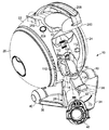
真空掃除機10は、分離装置12を支持するための支持体104を含む。支持体104は、転動組立体20の本体22の一部に接続され、この実施例では一体化されている。支持体104は、本体22から前方に延びて、入口ダクト28の入口部分44にわたって延びるようになる。本体22及びひいては支持体104は、分離装置が支持体40に取付けられたときに、支持体104が入口部分44の上面と係合し、それによってシャーシ32に対して入口部分44の枢動運動に干渉する程度までは変形しないように、比較的剛直な材料、好ましくはプラスチック材料から形成される。本体22から遠ざかるように位置する支持体104の端部は、外側容器14の基部18内に形成された凹部(図示せず)内に位置するように上向きに延びた差込口106を含む。凹部内の差込口106の位置決めにより、分離装置12が支持体104に取付けられたときに該支持体104に対する分離装置12の正確な角度アライメントが保証され、分離装置12の流体入口108が、出口部分46の流体出口110の上に及び該流体出口に接して位置するようになる。出口部分46には、流体出口110を囲む可撓性環状シールを備え、分離装置12の流体入口108の周辺に対して気密シールを形成する。
The
分離装置12が支持体104に取付けられたときに、外側容器14の長手方向軸線は、この実施例では30°から40°の範囲内の角度で枢動軸線Pに対して傾斜している。外側容器14の外壁16は、転動組立体20の本体22に取付けられた1対の弾性支持体112によって支持される。
When the separating
小型の外観を備えた真空掃除機10を提供するために、本体22及び支持体104は共に、入口ダクト28がそこを貫通して延びるスリーブ114を形成する。スリーブ114の長手方向軸線は、入口部分44の枢動軸線Pと同一直線上にある。入口ダクト28の入口部分44及び出口部分46は、スリーブ114の両側に位置する。従って、スリーブ114は、入口部分44の流体出口54、出口部分56の流体入口56、及び環状シール部材58、60を囲む。スリーブ114の内面は、出口部分46が本体22に取付けられるときに、出口部分46の外面上に位置する戻り止め118を受けるための凹部116を含む。凹部116は、戻り止め118と実質的に同じ輪郭を有し、入口部分44が枢動軸線Pの周りで枢動すると、スリーブ114に対して、ひいては分離装置12及び本体22に対して出口部分46の回転を抑制するようにする。
To provide the
分離装置12は、図7(a)及び図7(b)に示される。分離装置12の特定の全体形状は、分離装置12が使用されることになる真空掃除機のサイズ及びタイプによって異なる可能性がある。例えば、分離装置12の全長は、装置の直径に対して増減する可能性があり、又は基部18の形状が変わる可能性がある。
The
上述のように、分離装置12は、実質的に円筒形状である外壁16を有する外側容器14を含む。外側容器14の下側端部は、枢動部120によって外壁16に枢動可能に取り付けられた基部18によって閉鎖され、外壁16上に位置する溝と係合するキャッチ(図示せず)によって閉鎖位置に保持される。閉鎖位置では、基部18は、外壁16の下側端部に接して密封される。キャッチは、下向きの圧力がキャッチの最上部分に加えられた場合に、キャッチが溝から遠ざかるように移動して該溝から係合解除されるように、弾性的に変形可能である。この場合、基部18は、外壁16から脱落することになる。
As described above, the
特に図7(b)を参照すると、分離装置12は更に、外側容器14内に位置した集塵部122を含む。集塵部122は、ほぼ円筒状外壁124、及び集塵部122の上側端部において外壁124に接続されたほぼ円筒状内壁126、並びに内壁126の下側端部を閉鎖する基部128を有する。集塵部122の外壁124は、外壁16の半径方向内向きに位置し、これらの間に環状チャンバ130を形成するように間隔を置いて配置される。集塵部122の外壁124は、基部18と接触し(基部18が閉鎖位置にあるとき)、基部18によって保持される環状シール部材132に対して密封される。流体入口108は、外側容器14に対して接線方向に配置され(図6(a)に示す)、流入する汚れた流体が環状チャンバ124の周囲の螺旋状経路を強制的に辿るのを保証する。
With particular reference to FIG. 7 (b), the
環状チャンバ130からの流体出口は、穿孔シュラウドの形態で設けられる。シュラウドは、截頭円錐状の形状で形成された上側部分134、円筒部分136、及びそこから垂下するスカート138を有する。円筒部分136内には、多数の孔が形成される。スカート138は、外壁16に向かう方向で円筒部分136から外向きに先細になる。
The fluid outlet from the
シュラウドの上側部分134は、サイクロンパック140に接続される。サイクロンパック140は、集塵部122の上側端部に取付けられ、外側容器14の上側端部と係合するための円周方向フランジ142を含む。サイクロンパック140は、外側容器14の上側端部に隣接する外壁16に対して密封するための環状シール144を保持する。
The shroud
サイクロンパック140は、サイクロン146の環状アレイを含む。サイクロン146は平行に配置される。好ましい実施形態では、この容器直径に対して12個のサイクロン146があり、外側容器14の長手方向軸線を中心としてリング状に配置される。各サイクロン16は、長手方向軸線に向かって下向きに傾斜した軸線を有する。12個のサイクロン146は、第2のサイクロン分離ユニットを形成すると考えることができ、環状チャンバ130が第1のサイクロン分離ユニットを形成する。第2のサイクロン分離ユニットでは、各サイクロン146は、環状チャンバ124よりも小さな直径を有するので、第2のサイクロン分離ユニットは、第1のサイクロン分離ユニットよりも微細な汚れ及び塵埃粒子を分離することができる。第2のサイクロン分離ユニットはまた、第1のサイクロン分離ユニットによって既に清浄化されている流体流に対して取り組むという追加の利点を有し、その結果、同伴粒子の量及び平均サイズがそうでなかった場合よりも小さくなる。第2のサイクロン分離ユニットの分離効率は、第1のサイクロン分離ユニットの分離効率よりも高い。
各サイクロン146は、他のサイクロン146と同一であり、接線方向入口148を有する円筒上側部分と、上側部分から垂下する先細部分とを含む。各サイクロン146の先細部分は、截頭円錐形状であり、円錐開口部150で終端する。各先細部分は、円錐開口部150が、集塵部122の外壁124と内壁126との間に位置するチャンバ152内に位置するように、集塵部122の上側端部に形成された孔を通って突出する。
Each
集塵部122の内壁126及び基部128は、フィルタハウジング154の下側部分を形成する。フィルタハウジング154の上側部分は、集塵部122の上側端部に取付けられたほぼ環状のフィルタハウジング部材156によって提供され、これは、集塵部122の内壁126と共にフィルタハウジング154のほぼ連続的な内壁を形成する。サイクロンパック140は、フィルタハウジング部材156を囲み、該フィルタハウジング部材156と共に、シュラウドの孔を通過した流体をサイクロン146の入口148に搬送するためのプレナムチャンバ158を形成する。
The
サイクロン146の開放上側端部は、環状排出マニホルドによって閉鎖される。排出マニホルドは、上側部分160及び下側部分162を含む。開口を備えたシール部材163は、サイクロンパック140と排出マニホルドの下側部分162との間に設けることができる。排出マニホルドの下側部分162は、流体がサイクロン146から流出するのを可能にする渦ファインダ164を含む。各渦ファインダ164は、排出マニホルドの上側部分160と下側部分162との間に形成されたマニホルドフィンガ166と連通する。各マニホルドフィンガ166は、ほぼ逆U字形であって、それぞれのサイクロン146の上側端部から、排出マニホルドの上側部分160に形成されたほぼ円筒状の排出マニホルド壁168まで延びる。壁168は、マニホルドフィンガ166のそれぞれの部分から流体を各々が受け入れる複数の孔170を含む。壁168は、外壁16とほぼ同軸のボアの周りに延びる。
The open upper end of the
孔170は、流体をフィルタハウジング154に搬送する。フィルタ組立体180は、フィルタハウジング154内に位置する。フィルタ組立体180は、排出マニホルドの上側部分162のボアを通ってフィルタハウジング154内に挿入される。フィルタ組立体180は、本体182と、フィルタ本体182に取付けられたフィルタ184とを含む。フィルタ本体182は、好ましくはプラスチック材料から成形された一体成形品であるのが好ましいが、代わりとして、フィルタ本体182は、共に接続された複数の構成要素から形成されてもよい。フィルタ本体182は、ほぼ管状の形状であり、環状体186と、本体186の内面に接続され且つそこから垂下する半径方向に延びる細長スポーク188のセットとを含む。細長フィン190のセットは、各フィン190が隣接するスポーク188間に位置するようにスポーク188間に接続される。フィン190は、コネクタ192によってスポーク188に接続される。スポーク188及びフィン190は共に、フィルタ184を支持するための支持体を提供する。
The
フィルタ184は、フィルタ本体182のスポーク188及びフィン190の周りに延びるソックフィルタの形態である。フィルタ184の上側端部は、フィルタ本体182内に形成された環状溝内部に保持されるカラー194を含む。フィルタ184の下側端部は、フィルタハウジング154へのフィルタ組立体180の挿入を容易にするために、フィルタ184の下側端部を閉鎖する基部又は端部キャップ196を含む。
フィルタ184は更に、フィルタハウジング154を通過する流体流から塵埃及び他の粒子状物質を除去するために、様々な濾過レベルの複数の管状フィルタ部材を含む。最も微細な濾過レベルを有するフィルタ部材は、好ましくは最大の表面積を有する。フィルタ組立体180の各フィルタ部材は、矩形又は先細形状で製造される。次いで、フィルタ部材は、縫合、接着又は他の好適な技術によってこれらの最長縁部に沿って共に接合及び固定され、実質的に開放円筒形状を有するフィルタ材料の管状長さを形成するようにする。次に、各円筒フィルタ部材の上側端部はカラー194に取り付けられ、一方、各フィルタ部材の下側端部は、例えば、フィルタ組立体180の製造中にカラー194及び端部キャップ196の材料をオーバーモールド成形することによって、端部キャップ196に取り付けられる。フィルタ部材を取り付ける代替の製造技術は、フィルタ部材の上側及び下側端部の周囲のポリウレタンの接着及び回転成形を含む。このようにして、フィルタ部材は、製造工程中にポリウレタンによって封入され、ユーザによる操作及び取り扱いに耐えることができる密封機構を生成するようにする。
フィルタ本体182は、出口ダクト30の空気入口200と係合する環状シール部材198を含む。図1及び図2(a)を参照すると、この実施例では、出口ダクト30の空気入口200は、ほぼドーム形であり、フィルタ本体182の開放上側端部202を通ってフィルタ組立体180に入り、シール部材198と係合してこれらの間に気密シールを形成するようにする。シール部材198は、組み立て中にフィルタ本体182でオーバーモールド成形するか、或いは、フィルタ本体182に取り付けることができる。代替として、シール部材198は、フィルタ本体182と一体化されてもよい。
The
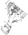
出口ダクト30は、一般に、分離装置12と転動組立体20との間に延びる湾曲アームの形態である。出口ダクト30は、分離装置12に対して移動可能であり、分離装置12を真空掃除機10から取り外すことを可能にし、更に、フィルタ組立体180を分離装置12のフィルタハウジング154から取り外すことを可能にする。出口ダクト30の空気入口200から離れて位置する管状出口ダクト30の端部は、転動組立体20の本体22に枢動可能に接続されて、出口ダクト30が分離装置12と流体連通状態にある下降位置と、分離装置12を真空掃除機10から取り外すことが可能な上昇位置との間で出口ダクト30が移動できるようにする。
The
出口ダクト30は、本体22内に位置する弾性部材(図示せず)によって上昇位置に向かって付勢される。本体22は、弾性部材の力に抗して下降位置に出口ダクト30を保持するための付勢キャッチ204と、キャッチ解除ボタン206とを含む。出口ダクト30は、出口ダクト30が下降位置に保持されたときに、真空掃除機10をユーザが持ち運ぶのを可能にするハンドル208を含む。或いは、出口ダクト30を用いて真空掃除機10を持ち運ぶこともできる。キャッチ204は、出口ダクト30に接続されたフィンガ210と協働して、その下降位置に出口ダクトを保持するように構成される。キャッチ解除ボタン206が押下されると、キャッチ204に加えられた付勢力に抗してキャッチ204がフィンガ210から遠ざかるように移動し、弾性部材が出口ダクト30を上昇位置に移動させることができる。
The
次に、図6(a)及び図8を参照して転動組立体20を説明する。転動組立体20は、本体22と、床面と係合するために本体22に回転可能に接続された2つの湾曲ホイール24、26とを含む。この実施形態では、本体22及びホイール24、26は、実質的に球状の転動組立体20を形成する。この実施例では、本体20は、上側部分212と、該上側部分212に接続された下側部分214とを含む。支持体106は、上側部分212と一体化され、シャーシ32は下側部分214と一体化される。ホイール24は、本体22の下側部分214に接続された車軸216に取付けられ、ホイール26は、本体22の上側部分212に接続された車軸218に取付けられている。車軸216、218は、ホイール24、26の回転軸線が真空掃除機10の位置する床面に対して本体22に向かって上向きに傾斜するように配置され、その結果、ホイール24、26のリムが床面と係合するようになる。ホイール24、26の回転軸線の傾斜角度は、床面との点接触を最小にするように、好ましくは4°から15°の範囲、より好ましくは5°から10°の範囲である。
Next, the rolling
転動組立体20のホイール24、26の各々は、ほぼドーム形である。各ホイール24、26は、その周辺の周りの外側部材220に接続された外側ホイール部材220及び内側ホイール部材222を含む。外側ホイール部材220及び内側ホイール部材222は、好ましくは、スピン溶接技術を用いて共に接続される。好ましくは、ホイール部材220、222間で複数の環状接続が行われる。この実施例では、ホイール部材220、222は、3つの異なる位置P1、P2及びP3にて共に接合され、これらの各々は、図8に示されている。位置P1は、ホイール部材220、222の外側リムにおいて又はこれらに向かって位置し、P3は、ホイール部材220、222の中心において又はこれに向かって位置し、P2は、位置P1とP3のほぼ中間に位置する。外側ホイール部材220の内面及び内側ホイール部材222の外面は、これらの位置の各々において位置する相互係合特徴部を含む。例えば、ホイール部材220、222の1つは、他のホイール部材220、222上に形成されたそれぞれの隆起円形帯を各々が受けるために一連の円形溝を含むことができる。
Each of the
ホイール部材220、222は、比較的剛直な材料から形成され、好ましくはプラスチック材料から形成される。例えば、ホイール部材220、222の各々は、好ましくは、ガラス充填ポリプロピレン、好ましくは30%ガラス充填ポリプロピレンから形成される。代替として、ホイール部材220、222は、異なるプラスチック材料から形成することができる。例えば、外側ホイール部材220は、20%ガラス充填ポリプロピレンから形成することができる。
The
内側ホイール部材222は、外側ホイール部材220を張力状態に維持するように成形される。これは、ホイール24、26の外面を比較的剛直にし、これによって、例えば、清掃作業中に物体との衝突によるホイール24、26が変形する傾向を低減することができる。
内側ホイール部材222は、ホイール24、26をその車軸216、218上で回転可能に支持するための環状軸受機構224を含む。組み立て中、ホイール24、26は、これらのそれぞれの車軸216、218の上に位置し、ファスナ226は、車軸216、218上にホイール24、26を保持するように軸受機構224の上に接続される。
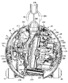
転動組立体20は、モータ駆動ファンユニット228と、とりわけファンユニット228のモータに電力を供給するプラグ232にて終端する電気ケーブル(図示せず)の一部分を本体22内に引き込んで格納するためのケーブル巻き戻し組立体230と、少なくとも1つのフィルタ組立体234とを収納する。ファンユニット228は、汚れを含む流体流を真空掃除機10に通じてこれに引き込むように、モータと、該モータによって駆動するインペラとを含む。ファンユニット228は、モータバケット236に収納される。モータバケット236は、真空掃除機10が床面にわたって操縦されるときにファンユニット228が回転しないように、本体22の下側部分214に接続される。この実施例では、フィルタ組立体234は、ファンユニット228の下流側に位置する。フィルタ組立体234は、カフ形であり、モータバケット236の一部の周りに位置する。複数の穿孔が、フィルタ組立体234によって囲まれるモータバケット236の一部に形成され、空気がモータバケット236からフィルタ組立体234に貫通できるようにする。
The rolling
フィルタ組立体234は、転動組立体20から定期的に取り外し、フィルタ組立体234を掃除可能にすることができる。フィルタ組立体234は、転動組立体20のホイール26を取り外すことによってアクセスされる。このホイール26は、例えば、ユーザが最初にファスナ226を取り外し、次いで、車軸218からホイール26を引き寄せることによって取り外すことができる。次に、フィルタ組立体234は、フィルタ組立体234をモータバケット236に接続するキャッチを押下し、転動組立体20からフィルタ組立体234を引き寄せることによって転動組立体20から取り外すことができる。
The
転動組立体20の本体22は更に、出口ダクト30から受け入れた流体流をモータバケット236に搬送するためのモータ入口ダクト238を含む。モータ入口ダクト238は、転動組立体20の本体22の上側部分212に接続され、流体入口240及び流体出口242を有する。ケーブル巻き戻し組立体230は、流体出口242とは反対側にあるモータ入口ダクト238の側面に取付けられている。環状シート244は、モータバケット236とモータ入口ダクト238との間に設けることができる。ファンユニット228は、ファンユニット228の外周の周りに位置する一連の排出ダクト246を含む。好ましい実施形態では、複数の排出孔246がファンユニット228の周りに配置され、ファンユニット228とモータバケット236との間の連通を可能にする。
The
本体22は更に、真空掃除機10から清浄化された空気を排出するための空気排出ポートを含む。排出ポートは、本体22の後方に向かって形成される。好ましい実施形態では、排出ポートは、本体22の下側部分214に位置する幾つかのオリフィス248を含み、これらは、真空掃除機10の外側において、環境乱流が最小となるように位置決めされる。
The
第1のユーザ操作可能スイッチ250が本体上に設けられ、スイッチ250を押下したときにファンユニット228が通電するように配置される。ファンユニット228はまた、この第1のスイッチ250を押下することによって通電解除することができる。第2のユーザ操作可能スイッチ252は、第1のスイッチ250に隣接して設けられる。第2のスイッチ252により、ユーザは、ケーブル巻き戻し組立体230を起動することができる。真空掃除機10のファンユニット228、ケーブル巻き戻し組立体230及び他の補助構成要素を駆動するための回路254はまた、転動組立体20内に収納される。
A first user
使用時には、ファンユニット228は、ユーザがスイッチ250を押圧することによって起動され、汚れを含む流体流は、掃除機ヘッドの吸引開口部を通って真空掃除機10に引き込まれる。汚れを含む空気は、ホース及びワンド組立体を通過して入口ダクト28に入る。汚れを含む空気は、入口ダクト28を通過して分離装置12の汚れ空気入口108に入る。汚れ空気入口108の接線方向配置により、流体流は、外壁16に対して螺旋状経路を辿る。より大きな汚れ及び塵埃粒子は、環状チャンバ130におけるサイクロン作用によって堆積されてその中に収集される。
In use, the
部分的に清浄化された流体流は、シュラウドにおける孔を介して環状チャンバ130から出てプレナムチャンバ158に流入する。そこから流体流は、12個のサイクロン146に入り、更なるサイクロン分離によって、依然として流体流内に同伴している汚れ及び塵埃の一部が除去される。この汚れ及び塵埃は、集塵部122に堆積されるが、清浄空気は、渦ファインダ164を介してサイクロン146から出てマニホルドフィンガ166に流入する。次に、流体流は、孔170を通ってフィルタハウジング154に流れる。フィルタハウジング154内では、空気流は、フィルタ組立体180のフィルタ184を通過する。フィルタ本体のスポーク188及びフィン190によって提供さられる支持体は、空気流がフィルタ184を通過するときに該フィルタ184が圧潰するのを阻止する。その後、空気流は、フィルタ本体182を通って軸方向に流れ、フィルタ組立体180の空気出口202を通って出口ダクト30のドーム形空気入口200内に排出されるようにする。
The partially cleaned fluid stream exits the
空気流は、出口ダクト30を通過し、モータ入口ダクト238の流体入口240を通って転動組立体20の本体22に入る。モータ入口ダクト238は、流体流をファンユニット228に案内する。その後、流体流は、ファンユニット228の側面の排出孔246を通ってモータバケット236内に排出される。流体流は、穿孔を通ってモータバケット236から離れ、フィルタ組立体234を通過する。最終的に、流体流は、本体22の湾曲に沿って、本体22のオリフィス248へ流れ、ここから清浄化された流体流が真空掃除機10から取り出される。
The air flow passes through the
使用中に、フィルタ組立体180が目詰まりし、濾過効率の低下を引き起こす可能性があるので、フィルタ組立体180は、定期的な清浄化又は交換が必要となる。好ましい実施形態では、フィルタ組立体180は、洗浄によって掃除することができる。フィルタ組立体180は、出口ダクト30が上昇位置にあるときに、清浄化のためにユーザがアクセスすることができる。ユーザは、フィルタ本体182のスポーク188の1つを把持し、フィルタハウジング154からフィルタ組立体180を引き寄せることによって分離装置12からフィルタ組立体180を取り外す。フィルタ組立体180は、家庭用蛇口ですすぐことによって洗浄して乾燥させることができる。次に、フィルタ組立体180は、分離装置12のフィルタハウジング154に再挿入され、出口ダクト30がその下降位置まで移動して、真空掃除機10の使用を続けることができる。
During use, the
出口ダクト30がその上昇位置にあるときには、分離装置12は、排出及び清浄化のために真空掃除機10から取り外すことができる。分離装置12は、真空掃除機10から分離装置12の取り外しを容易にするハンドル250を含む。ハンドル250は、例えば、スクリュー又はスナップ嵌め接続によって排出マニホルド122の上側部分160に接続される。分離装置12を排出するために、ユーザは、排出マニホルドの上側部分160上に位置したボタン252を押下し、基部18上のキャッチの最上位置に下向きの圧力を加える機構を作動させるようにする。これによりキャッチが変形し、外側容器14の外壁16上に位置する溝から係合解除される。これは、基部18が外壁16から遠ざかるように移動し、分離装置12内に収集されている汚れ及び塵埃を塵埃容器又は他のレセプタクルに排出できるようにする。キャッチに力を加える機構は、好ましくは、ボタン252の押下に応答してキャッチに向かって移動する一連のプッシュロッドを含む。プッシュロッドを配置することで、外側ビン14をサイクロンパック140から分離することが可能になる。
When the
10 真空掃除機
22 本体
24、26、40 ホイール
28 入口ダクト
30 出口ダクト
32 シャーシ
34 側縁
38 パッド
44 入口部分
46 出口部分
48 カップリング
70 スロット
72 上昇壁
100 キャッチ
104 支持体
106 差込口、支持体
110 流体出口
112 弾性支持体
114 スリーブ
200 空気入口
208 ハンドル
232 プラグ
252 スイッチ、ボタン
DESCRIPTION OF
Claims (21)
汚れ含有流体流から汚れを分離するための分離装置と、
前記分離装置を通って前記流体流を引き込む手段を含む床係合転動組立体と、
前記転動組立体に接続されたシャーシと、
前記流体流を前記分離装置に搬送するため前記転動組立体に解放可能に接続される出口部分と、前記出口部分及び前記シャーシに対して枢動運動するため前記シャーシに接続された入口部分と、を含むダクトと、
を備える、ことを特徴とする掃除用電気器具。 A cylindrical cleaning appliance,
A separation device for separating dirt from a dirt-containing fluid stream;
A floor engagement rolling assembly including means for drawing the fluid stream through the separation device;
A chassis connected to the rolling assembly;
An outlet portion releasably connected to the rolling assembly for conveying the fluid stream to the separation device; and an inlet portion connected to the chassis for pivoting relative to the outlet portion and the chassis; A duct including
An electrical appliance for cleaning, comprising:
Applications Claiming Priority (2)
| Application Number | Priority Date | Filing Date | Title |
|---|---|---|---|
| GB1016450.7A GB2484122A (en) | 2010-09-30 | 2010-09-30 | A cylinder type cleaning appliance |
| GB1016450.7 | 2010-09-30 |
Publications (2)
| Publication Number | Publication Date |
|---|---|
| JP2012075896A JP2012075896A (en) | 2012-04-19 |
| JP5366335B2 true JP5366335B2 (en) | 2013-12-11 |
Family
ID=43243282
Family Applications (1)
| Application Number | Title | Priority Date | Filing Date |
|---|---|---|---|
| JP2011216491A Expired - Fee Related JP5366335B2 (en) | 2010-09-30 | 2011-09-30 | Cleaning appliance |
Country Status (5)
| Country | Link |
|---|---|
| US (1) | US9974421B2 (en) |
| EP (1) | EP2436290B9 (en) |
| JP (1) | JP5366335B2 (en) |
| CN (1) | CN102440720B (en) |
| GB (1) | GB2484122A (en) |
Families Citing this family (32)
| Publication number | Priority date | Publication date | Assignee | Title |
|---|---|---|---|---|
| GB2469038B (en) * | 2009-03-31 | 2013-01-02 | Dyson Technology Ltd | A cleaning appliance |
| GB2469051B (en) * | 2009-03-31 | 2013-01-02 | Dyson Technology Ltd | A cleaning appliance with steering mechanism |
| AU2010231171B2 (en) * | 2009-03-31 | 2014-03-13 | Dyson Technology Limited | Cylinder type vacuum cleaner |
| GB2469046B (en) * | 2009-03-31 | 2012-07-25 | Dyson Technology Ltd | Mounting arrangement for separating apparatus in a cleaning appliance |
| GB2469047B (en) * | 2009-03-31 | 2013-12-04 | Dyson Technology Ltd | A cylinder type cleaning appliance |
| WO2010112885A1 (en) * | 2009-03-31 | 2010-10-07 | Dyson Technology Limited | A cleaning appliance |
| GB2469048B (en) * | 2009-03-31 | 2013-05-15 | Dyson Technology Ltd | Cleaning appliance with steering mechanism |
| GB2469045B (en) * | 2009-03-31 | 2012-08-29 | Dyson Technology Ltd | Duct and chassis arrangement of a cleaning apparatus |
| GB2469055B (en) * | 2009-03-31 | 2013-01-02 | Dyson Technology Ltd | A cleaning appliance with spherical floor engaging arrangement |
| GB2469053B (en) * | 2009-03-31 | 2013-02-06 | Dyson Technology Ltd | A cleaning appliance having pivotal movement |
| GB2469049B (en) * | 2009-03-31 | 2013-04-17 | Dyson Technology Ltd | A cleaning appliance with steering mechanism |
| GB2484121B (en) | 2010-09-30 | 2014-10-22 | Dyson Technology Ltd | A vacuum cleaning appliance |
| GB2484120B (en) | 2010-09-30 | 2014-10-01 | Dyson Technology Ltd | A cleaning appliance |
| GB2484124B (en) | 2010-09-30 | 2014-12-03 | Dyson Technology Ltd | A cleaning appliance |
| IN2014DN07603A (en) * | 2012-03-06 | 2015-05-15 | Dyson Technology Ltd | |
| GB2500017B (en) | 2012-03-06 | 2015-07-29 | Dyson Technology Ltd | A Humidifying Apparatus |
| GB2512192B (en) | 2012-03-06 | 2015-08-05 | Dyson Technology Ltd | A Humidifying Apparatus |
| GB2500012B (en) | 2012-03-06 | 2016-07-06 | Dyson Technology Ltd | A Humidifying Apparatus |
| GB2503254B (en) | 2012-06-20 | 2014-12-17 | Dyson Technology Ltd | A cleaning appliance |
| GB2503255B (en) | 2012-06-20 | 2014-10-15 | Dyson Technology Ltd | A cleaning appliance |
| GB2503253B (en) * | 2012-06-20 | 2014-10-15 | Dyson Technology Ltd | A cleaning appliance |
| GB2503252B (en) | 2012-06-20 | 2014-12-17 | Dyson Technology Ltd | A self righting cleaning appliance |
| GB2503251C (en) | 2012-06-20 | 2015-07-15 | Dyson Technology Ltd | A self righting cleaning appliance |
| GB2503671B (en) | 2012-07-03 | 2014-12-17 | Dyson Technology Ltd | Control of a brushless motor |
| GB2503670B (en) | 2012-07-03 | 2014-12-10 | Dyson Technology Ltd | Method of preheating a brushless motor |
| WO2014118501A2 (en) | 2013-01-29 | 2014-08-07 | Dyson Technology Limited | A fan assembly |
| AU2016211669C1 (en) | 2015-01-26 | 2020-05-07 | Hayward Industries, Inc. | Swimming pool cleaner with hydrocyclonic particle separator and/or six-roller drive system |
| US9885196B2 (en) | 2015-01-26 | 2018-02-06 | Hayward Industries, Inc. | Pool cleaner power coupling |
| US11241129B2 (en) * | 2016-04-11 | 2022-02-08 | Omachron Intellectual Property Inc. | Surface cleaning apparatus |
| US9896858B1 (en) | 2017-05-11 | 2018-02-20 | Hayward Industries, Inc. | Hydrocyclonic pool cleaner |
| US9885194B1 (en) | 2017-05-11 | 2018-02-06 | Hayward Industries, Inc. | Pool cleaner impeller subassembly |
| US10156083B2 (en) | 2017-05-11 | 2018-12-18 | Hayward Industries, Inc. | Pool cleaner power coupling |
Family Cites Families (160)
| Publication number | Priority date | Publication date | Assignee | Title |
|---|---|---|---|---|
| US963139A (en) | 1909-05-17 | 1910-07-05 | Daniel D Griffiths | Pneumatic suction-cleaner. |
| US1123839A (en) | 1913-11-10 | 1915-01-05 | Universal Swing Joint And Machine Company | Fitting for pipes and rods. |
| US1301453A (en) | 1918-07-20 | 1919-04-22 | Ira Hunt Kendall | Sanitary fitting or coupling for pipes. |
| US1605507A (en) | 1924-01-18 | 1926-11-02 | Thomas J Burke | Universal pipe joint |
| US1918713A (en) * | 1928-05-26 | 1933-07-18 | Robert A Ponselle | Vacuum cleaner |
| US1861402A (en) | 1931-04-24 | 1932-05-31 | Lewis C Van Riper | Bag clamp for suction cleaners |
| USRE21519E (en) | 1937-02-27 | 1940-07-30 | Vacuum cleaner muffler | |
| US2352504A (en) * | 1939-08-11 | 1944-06-27 | Hoover Co | Suction cleaner |
| USRE22426E (en) | 1939-12-13 | 1944-01-25 | Suction cleanek | |
| GB645847A (en) | 1946-10-10 | 1950-11-08 | Edgar Peter Senne | Improvements in or relating to vacuum cleaners |
| US2489100A (en) | 1946-11-14 | 1949-11-22 | Marco John | Detachable and adjustable pipe coupling |
| US2738538A (en) | 1951-04-03 | 1956-03-20 | Hoover Co | Suction cleaner having filter structure encasing and supported by an electric cord |
| US2699838A (en) | 1952-01-18 | 1955-01-18 | John N Ledbetter Jr | Vacuum cleaner |
| US2686330A (en) * | 1953-01-02 | 1954-08-17 | Ind Patent Corp | Ball-roll vacuum cleaner |
| US2747216A (en) * | 1953-06-05 | 1956-05-29 | Hoover Co | Suction cleaners |
| US2834605A (en) | 1953-11-27 | 1958-05-13 | Alan E Grimley | Wheeled vehicle with differential steering mechanism |
| US2771309A (en) | 1954-06-10 | 1956-11-20 | Clark Metal Products Inc | Universal ball and socket joint |
| BE543059A (en) * | 1954-11-24 | |||
| US2876479A (en) * | 1955-11-10 | 1959-03-10 | Hoover Co | Suction cleaner transport accessory |
| US3038743A (en) | 1959-04-30 | 1962-06-12 | Zaloumis Angelos | Flexible pipe coupling with hemispherical coupling elements |
| FR1310618A (en) | 1961-10-17 | 1962-11-30 | Vacuum | |
| US3310828A (en) * | 1964-06-10 | 1967-03-28 | Direct Sales Inc | Vacuum cleaner |
| JPS4329416Y1 (en) * | 1965-05-14 | 1968-12-03 | ||
| GB1122619A (en) | 1965-06-16 | 1968-08-07 | Electrolux Ltd | Improved vacuum cleaner |
| US3375541A (en) | 1966-06-24 | 1968-04-02 | Singer Co | Vacuum cleaners with combined hose connectors and housing latches |
| NL6711520A (en) | 1967-08-22 | 1969-02-25 | ||
| US3524212A (en) | 1968-04-03 | 1970-08-18 | Haley Corp | Latching mechanism for vacuum cleaner |
| US3608333A (en) * | 1968-06-20 | 1971-09-28 | Bison Mfg Co Inc | Vacuum cleaner and power unit |
| US3524211A (en) | 1968-07-05 | 1970-08-18 | Haley Corp | Vacuum cleaner with air director tube |
| AR208338A1 (en) * | 1974-11-12 | 1976-12-20 | Hellenic Plastics Rubber | FAST ACTING PLASTIC MATERIAL COUPLING FOR COUPLING TUBULAR PARTS |
| US4114231A (en) | 1977-03-04 | 1978-09-19 | Nauta Jelle G | Motor ventilation system for wet/dry vacuum cleaner |
| GB1596794A (en) | 1977-07-06 | 1981-08-26 | Shotbolt K | Pipe connectors |
| JPS5570228A (en) * | 1978-11-21 | 1980-05-27 | Matsushita Electric Ind Co Ltd | Vacuum cleaner |
| JPS56164743U (en) * | 1980-05-12 | 1981-12-07 | ||
| US4573236A (en) | 1983-07-08 | 1986-03-04 | Prototypes, Ltd. | Vacuum cleaning appliances |
| US5144716A (en) | 1988-10-07 | 1992-09-08 | Hitachi, Ltd. | Electric cleaner, method for producing same and mount base and bumper for electric cleaner |
| JP2574425B2 (en) | 1988-10-17 | 1997-01-22 | 松下電器産業株式会社 | Self-propelled vacuum cleaner |
| JPH0330A (en) | 1989-05-29 | 1991-01-07 | Mitsubishi Electric Home Appliance Co Ltd | Vacuum cleaner |
| JP2907894B2 (en) | 1989-09-29 | 1999-06-21 | 株式会社日立製作所 | Electric vacuum cleaner |
| JP2928352B2 (en) | 1990-08-21 | 1999-08-03 | マツダ株式会社 | Engine control device |
| US5149147A (en) | 1991-04-18 | 1992-09-22 | General Electric Company | Conduit coupling for high temperature, high pressure applications |
| US5224238A (en) | 1991-04-18 | 1993-07-06 | Ryobi Motor Products Corp. | Horizontal canister vacuum |
| JPH0591956A (en) | 1991-10-01 | 1993-04-16 | Matsushita Electric Ind Co Ltd | Vacuum cleaner |
| JPH05168577A (en) * | 1991-12-24 | 1993-07-02 | Hitachi Ltd | Vacuum cleaner |
| US5275444A (en) | 1992-09-21 | 1994-01-04 | Wythoff Johan G | Swivel hose coupling for pressurized fluid, fuel and gas systems |
| US5467500A (en) | 1993-01-27 | 1995-11-21 | Aar Corp. | Steering mechanism for a cleaning vehicle |
| JP3211121B2 (en) | 1993-12-28 | 2001-09-25 | 株式会社日立製作所 | Electric vacuum cleaner |
| JP3209016B2 (en) * | 1993-10-20 | 2001-09-17 | 株式会社日立製作所 | Electric vacuum cleaner |
| DK119093A (en) | 1993-10-22 | 1995-04-23 | Joergen Sjoegreen | Universal Vacuum Cleaner |
| CN1118241A (en) * | 1994-06-22 | 1996-03-13 | 大宇电子株式会社 | Dual mode vacuum cleaner |
| GB2297243A (en) * | 1995-01-27 | 1996-07-31 | Notetry Ltd | Vacuum cleaner for use on stairs |
| US5842254A (en) | 1995-03-31 | 1998-12-01 | Daewoo Electronics Co., Ltd. | Dual mode vacuum cleaner |
| JP3528325B2 (en) | 1995-05-26 | 2004-05-17 | 株式会社日立製作所 | Electric vacuum cleaner |
| WO1997012168A1 (en) | 1995-09-28 | 1997-04-03 | Philips Electronics N.V. | Tube coupling with axially movable unlocking slide |
| KR970032722A (en) | 1995-12-19 | 1997-07-22 | 최진호 | Cordless cleaner |
| US5784757A (en) | 1996-01-11 | 1998-07-28 | Royal Appliance Mfg. Co. | Vacuum cleaner hose assembly |
| CH691565A5 (en) * | 1996-09-26 | 2001-08-31 | Certech Sa | Vacuum cleaner for household waste. |
| JPH10278835A (en) | 1997-04-11 | 1998-10-20 | Nippon Oirumikisaa Kk | Steering mechanism of racing cart |
| KR100215231B1 (en) | 1997-06-02 | 1999-08-16 | 이세용 | Screw spindle for a revolving chair |
| IT1292121B1 (en) | 1997-06-10 | 1999-01-25 | Omec Spa | TELESCOPIC EXTENSION FOR A ELECTRIC APPLIANCE AND MANUFACTURING PROCEDURE FOR SAID TELESCOPIC EXTENSION |
| JP3609582B2 (en) * | 1997-06-23 | 2005-01-12 | 三洋電機株式会社 | Electric vacuum cleaner |
| US6371421B1 (en) | 1997-08-23 | 2002-04-16 | Samhongsa Co., Ltd. | Device for controlling the height of a swivel chair |
| SE9800405D0 (en) | 1998-02-12 | 1998-02-12 | Electrolux Ab | Handle for a vacuum cleaner |
| US6158781A (en) | 1998-05-18 | 2000-12-12 | Taper-Lok | Pipeline swivel coupling |
| TW578540U (en) | 1998-07-28 | 2004-03-01 | Sharp Kk | Electric vacuum cleaner and nozzle unit therefor |
| GB9823418D0 (en) | 1998-10-26 | 1998-12-23 | Notetry Ltd | Cyclonic seperating apparatus |
| US6334234B1 (en) | 1999-01-08 | 2002-01-01 | Fantom Technologies Inc. | Cleaner head for a vacuum cleaner |
| US6251296B1 (en) | 1999-07-27 | 2001-06-26 | G.B.D. Corp. | Apparatus and method for separating particles from a cyclonic fluid flow |
| DE29913775U1 (en) | 1999-08-06 | 1999-12-30 | Vorwerk Co Interholding | Floor care device, in particular vacuum cleaner |
| CA2292317C (en) | 1999-08-13 | 2004-05-04 | Samsung Kwangju Electronics Co., Ltd. | Stick-type vacuum cleaner |
| US6484350B2 (en) | 1999-12-08 | 2002-11-26 | Shell Electric Mfg. (Holdings) Co. Ltd. | Bagless canister vacuum cleaner |
| IT1315385B1 (en) * | 2000-02-01 | 2003-02-10 | T P A Impex Spa | STEERING GROUP PARTICULARLY FOR HOUSEHOLD AND / OR INDUSTRIAL CLEANING MACHINES. |
| JP2001314356A (en) | 2000-03-01 | 2001-11-13 | Matsushita Electric Ind Co Ltd | Electric vacuum cleaner |
| CN1143651C (en) | 2000-03-01 | 2004-03-31 | 松下电器产业株式会社 | Electric suction cleaner |
| US20020011050A1 (en) | 2000-05-05 | 2002-01-31 | Hansen Samuel N. | Suction cleaner with cyclonic dirt separation |
| WO2002017766A2 (en) | 2000-09-01 | 2002-03-07 | Royal Appliance Mfg. Co. | Bagless canister vacuum cleaner |
| KR100382451B1 (en) | 2000-11-06 | 2003-05-09 | 삼성광주전자 주식회사 | Cyclone dust-collecting apparatus for vacuum cleaner |
| DE10059052A1 (en) | 2000-11-28 | 2002-06-06 | Froh House Tech Gmbh & Co Kg | Telescopic vacuum cleaner suction pipe |
| EP1210899A1 (en) | 2000-12-01 | 2002-06-05 | Nilfisk-Advance A/S | A vacuum cleaner |
| CN1136812C (en) | 2000-12-29 | 2004-02-04 | 维斯尔-韦克有限公司 | Vacuum dust-collecting device for domestic cleaner |
| JP3283503B1 (en) | 2001-05-30 | 2002-05-20 | 株式会社日立製作所 | Electric vacuum cleaner |
| JP3583087B2 (en) | 2001-07-13 | 2004-10-27 | 東芝テック株式会社 | Electric vacuum cleaner |
| US6832409B2 (en) | 2001-09-18 | 2004-12-21 | The Hoover Company | Wet/dry floor cleaning unit and method of cleaning |
| JP2002355199A (en) | 2001-09-20 | 2002-12-10 | Hitachi Ltd | Vacuum cleaner |
| SE520237C2 (en) * | 2001-10-25 | 2003-06-10 | Electrolux Ab | Front wheel arrangement for a vacuum cleaner |
| GB0126494D0 (en) | 2001-11-03 | 2002-01-02 | Dyson Ltd | A floor tool |
| FR2833826B1 (en) | 2001-12-24 | 2005-06-03 | Denis Deleval | WHEEL VACUUM (S) ORIENTABLE (S) |
| KR100487306B1 (en) | 2001-12-28 | 2005-05-03 | 엘지전자 주식회사 | vacuum cleaner |
| JP2003211025A (en) | 2002-01-18 | 2003-07-29 | Sanyo Electric Co Ltd | Cyclone type dust collecting device and electric vacuum cleaner using the same |
| GB0203147D0 (en) | 2002-02-11 | 2002-03-27 | Dyson Ltd | An exhaust assembly |
| JP2003310491A (en) | 2002-04-23 | 2003-11-05 | Hitachi Home & Life Solutions Inc | Electric vacuum cleaner |
| JP2003325392A (en) | 2002-05-08 | 2003-11-18 | Matsushita Electric Ind Co Ltd | Vacuum cleaner |
| US7185389B2 (en) * | 2002-05-30 | 2007-03-06 | Great Lakes Engineering + Design, Inc. | Universal wet/dry vacuum cart |
| GB2391459A (en) | 2002-08-09 | 2004-02-11 | Dyson Ltd | A surface treating appliance with increased manoeuverability |
| KR20040023285A (en) | 2002-09-11 | 2004-03-18 | 엘지전자 주식회사 | Caster for vacuum cleaner and main body having the same |
| GB2393110A (en) | 2002-09-14 | 2004-03-24 | Dyson Ltd | A cleaning appliance and hose storage means therefor |
| US7181804B2 (en) | 2002-11-07 | 2007-02-27 | Panasonic Corporation Of North America | Removable dirt cup assembly with external filter |
| US6954966B2 (en) | 2002-11-12 | 2005-10-18 | Izumi Products Company | Cleaner for use in nursing care |
| US6786947B2 (en) | 2002-12-16 | 2004-09-07 | Robin A. Mountford | Washable cloth vacuum cleaner filter bag having a resealable opening for emptying vacuumed debris |
| US7025390B2 (en) | 2003-02-20 | 2006-04-11 | Wolf Creek Company, Inc. | Method and apparatus for connecting coupler fittings to conduit sections |
| CN2684749Y (en) | 2003-03-12 | 2005-03-16 | 松下电器产业株式会社 | Electric suction cleaner |
| JP2004310385A (en) | 2003-04-04 | 2004-11-04 | Amenity Technos:Kk | Self-propelled cleaning device and self-propelled cleaning method |
| GB2402046B (en) | 2003-05-27 | 2006-09-13 | Dyson Ltd | A cleaning appliance |
| CA2432974A1 (en) | 2003-06-20 | 2004-12-20 | Shell Electric Mfg. (Holdings) Co., Ltd. | Bagless vacuum cleaner with helical passageway |
| KR100536503B1 (en) | 2003-09-09 | 2005-12-14 | 삼성광주전자 주식회사 | A cyclone separating apparatus and vacumm cleaner equipped whth such a device |
| EP1535563A3 (en) * | 2003-11-26 | 2005-12-21 | South Asia International (H.K.) Ltd. | Water filtration vacuum cleaner |
| DE102004005461A1 (en) | 2004-02-04 | 2005-08-25 | Vorwerk & Co. Interholding Gmbh | Roller casters/swiveling casters for a piece of furniture/an appliance have an axle and a running wheel held on the axle so as to have rotary movement |
| JP2005334450A (en) | 2004-05-28 | 2005-12-08 | Toshiba Tec Corp | Vacuum cleaner |
| US7380308B2 (en) | 2004-11-16 | 2008-06-03 | Samsung Gwangju Electronics Co., Ltd. | Vacuum cleaner |
| US7555808B2 (en) * | 2004-11-16 | 2009-07-07 | Samsung Gwangju Electronics Co., Ltd. | Vacuum cleaner having a cyclone dust collecting apparatus |
| KR101119615B1 (en) | 2004-12-13 | 2012-03-13 | 엘지전자 주식회사 | Vacuum cleaner |
| JP2008526449A (en) | 2005-01-18 | 2008-07-24 | エレクトラックス ホーム ケア プロダクツ,リミテッド | Vacuum cleaner with folding handle |
| CN2764289Y (en) | 2005-01-21 | 2006-03-15 | 泰怡凯电器(苏州)有限公司 | Vacuum cleaner |
| JP4476872B2 (en) | 2005-05-30 | 2010-06-09 | 三菱電機株式会社 | Vacuum cleaner |
| KR100712283B1 (en) | 2005-08-18 | 2007-04-27 | 주식회사 대우일렉트로닉스 | In-draft pipe mounting structure for vacuum cleaner having variable type of upright type to canister type |
| AU2006220438B2 (en) | 2005-09-23 | 2011-02-03 | Bissell Inc. | Vacuum cleaner with two stage filtration |
| US7587786B2 (en) * | 2005-11-03 | 2009-09-15 | The Scott Fetzer Company | Vacuum cleaner with removable handle |
| GB2433425B (en) | 2005-12-23 | 2010-11-17 | Cassidy Brothers Plc | Improvements relating to vacuum cleaners |
| US20070163073A1 (en) * | 2006-01-19 | 2007-07-19 | Arnold Sepke | Vacuum cleaner dustcup and conduit construction |
| DE102006008556B3 (en) * | 2006-02-22 | 2007-08-02 | Miele & Cie. Kg | Vacuum cleaner, riding on rollers, has signal transmitter limit switches at the rotating suction hose connection for a control to steer the rollers following the user's movements |
| EP1836941B1 (en) | 2006-03-14 | 2014-02-12 | Toshiba TEC Kabushiki Kaisha | Electric vacuum cleaner |
| AU2006249291B2 (en) | 2006-05-17 | 2009-02-26 | Lg Electronics Inc | Vacuum cleaner |
| WO2008070973A1 (en) * | 2006-12-15 | 2008-06-19 | Gbd Corp. | Vacuum cleaner with wheeled base |
| EP2106234A2 (en) * | 2007-01-22 | 2009-10-07 | Koninklijke Philips Electronics N.V. | Robotic cleaning head |
| EP2129274B1 (en) | 2007-03-28 | 2013-02-20 | LG Electronics Inc. | Vacuum cleaner |
| GB2448745A (en) | 2007-04-27 | 2008-10-29 | Hoover Ltd | An upright vacuum cleaner |
| US8032983B2 (en) | 2007-05-17 | 2011-10-11 | Bissell Homecare, Inc. | Dust cup latch for cyclone separator vacuum |
| GB2450736B (en) | 2007-07-05 | 2012-06-20 | Dyson Technology Ltd | Cyclonic separating apparatus |
| AU2008276858B2 (en) | 2007-07-16 | 2011-02-03 | Lg Electronics Inc. | Vacuum cleaner and method of controlling the same |
| JP2009022403A (en) * | 2007-07-18 | 2009-02-05 | Panasonic Corp | Vacuum cleaner |
| CN101357051A (en) * | 2007-08-02 | 2009-02-04 | 三星光州电子株式会社 | Suction port assembly of vacuum cleaner |
| US8079113B2 (en) * | 2007-08-14 | 2011-12-20 | Lg Electronics Inc. | Vacuum cleaner having abilities for automatic moving and posture control and method of controlling the same |
| GB2452548B (en) | 2007-09-08 | 2011-11-30 | Dyson Technology Ltd | A surface treating appliance |
| GB2452549B (en) | 2007-09-08 | 2012-03-21 | Dyson Technology Ltd | A surface treating appliance |
| GB2453995B (en) | 2007-10-25 | 2012-01-25 | Dyson Technology Ltd | A filter assembly |
| CA126036S (en) * | 2007-11-23 | 2009-01-22 | Dyson Ltd | Vacuum cleaner |
| KR101491002B1 (en) | 2007-12-05 | 2015-02-06 | 삼성전자주식회사 | Vacuum cleaner |
| CN101558981B (en) * | 2008-04-17 | 2013-09-25 | 乐金电子(天津)电器有限公司 | Dust separator for vacuum cleaner |
| JP4753990B2 (en) | 2008-12-11 | 2011-08-24 | 三洋電機株式会社 | Vacuum cleaner |
| JP2010154940A (en) * | 2008-12-26 | 2010-07-15 | Interport International Kk | Cleaner |
| GB2469052B (en) | 2009-03-31 | 2013-02-06 | Dyson Technology Ltd | A cleaning appliance with spherical rolling assembly |
| GB2469049B (en) * | 2009-03-31 | 2013-04-17 | Dyson Technology Ltd | A cleaning appliance with steering mechanism |
| GB2469047B (en) | 2009-03-31 | 2013-12-04 | Dyson Technology Ltd | A cylinder type cleaning appliance |
| GB2469053B (en) * | 2009-03-31 | 2013-02-06 | Dyson Technology Ltd | A cleaning appliance having pivotal movement |
| GB2469046B (en) * | 2009-03-31 | 2012-07-25 | Dyson Technology Ltd | Mounting arrangement for separating apparatus in a cleaning appliance |
| WO2010112885A1 (en) * | 2009-03-31 | 2010-10-07 | Dyson Technology Limited | A cleaning appliance |
| GB2469045B (en) | 2009-03-31 | 2012-08-29 | Dyson Technology Ltd | Duct and chassis arrangement of a cleaning apparatus |
| GB2469038B (en) | 2009-03-31 | 2013-01-02 | Dyson Technology Ltd | A cleaning appliance |
| GB2469051B (en) * | 2009-03-31 | 2013-01-02 | Dyson Technology Ltd | A cleaning appliance with steering mechanism |
| AU2010231171B2 (en) * | 2009-03-31 | 2014-03-13 | Dyson Technology Limited | Cylinder type vacuum cleaner |
| GB2469048B (en) * | 2009-03-31 | 2013-05-15 | Dyson Technology Ltd | Cleaning appliance with steering mechanism |
| GB2469039B (en) | 2009-03-31 | 2013-02-06 | Dyson Technology Ltd | A cleaning appliance |
| GB2469055B (en) | 2009-03-31 | 2013-01-02 | Dyson Technology Ltd | A cleaning appliance with spherical floor engaging arrangement |
| GB2474470B (en) * | 2009-10-15 | 2013-10-23 | Dyson Technology Ltd | A surface treating appliance |
| JP4941540B2 (en) | 2009-11-27 | 2012-05-30 | パナソニック株式会社 | Cyclone dust collector and electric vacuum cleaner provided with the same |
| CA2688800A1 (en) | 2009-12-17 | 2011-06-17 | Van Den Heuvel, Cristiaan | Improvements to hovering vacuum cleaners and components therefore |
| US8875340B2 (en) | 2010-03-12 | 2014-11-04 | G.B.D. Corp. | Surface cleaning apparatus with enhanced operability |
| GB2484121B (en) * | 2010-09-30 | 2014-10-22 | Dyson Technology Ltd | A vacuum cleaning appliance |
| GB2484124B (en) * | 2010-09-30 | 2014-12-03 | Dyson Technology Ltd | A cleaning appliance |
| GB2484120B (en) * | 2010-09-30 | 2014-10-01 | Dyson Technology Ltd | A cleaning appliance |
-
2010
- 2010-09-30 GB GB1016450.7A patent/GB2484122A/en not_active Withdrawn
-
2011
- 2011-09-02 EP EP11179939.1A patent/EP2436290B9/en not_active Not-in-force
- 2011-09-29 US US13/248,808 patent/US9974421B2/en not_active Expired - Fee Related
- 2011-09-30 JP JP2011216491A patent/JP5366335B2/en not_active Expired - Fee Related
- 2011-09-30 CN CN201110294560.9A patent/CN102440720B/en not_active Expired - Fee Related
Also Published As
| Publication number | Publication date |
|---|---|
| US9974421B2 (en) | 2018-05-22 |
| CN102440720B (en) | 2014-09-10 |
| JP2012075896A (en) | 2012-04-19 |
| EP2436290B1 (en) | 2015-06-17 |
| GB2484122A (en) | 2012-04-04 |
| US20120079673A1 (en) | 2012-04-05 |
| CN102440720A (en) | 2012-05-09 |
| EP2436290A2 (en) | 2012-04-04 |
| GB201016450D0 (en) | 2010-11-17 |
| EP2436290A3 (en) | 2012-12-05 |
| EP2436290B9 (en) | 2016-05-11 |
Similar Documents
| Publication | Publication Date | Title |
|---|---|---|
| JP5366335B2 (en) | Cleaning appliance | |
| JP5312547B2 (en) | Cleaning appliance | |
| JP5539285B2 (en) | Cleaning appliance | |
| JP5411904B2 (en) | Cleaning appliance | |
| JP5139467B2 (en) | Cleaning appliance | |
| JP5185972B2 (en) | Cleaning appliance | |
| JP5712163B2 (en) | Vacuum cleaning appliance | |
| JP5022466B2 (en) | Cleaning appliance | |
| JP5385843B2 (en) | Cleaning appliance | |
| JP5670380B2 (en) | Vacuum cleaning appliance | |
| JP2010240449A (en) | Electric appliance for cleaning | |
| JP2010240442A (en) | Electric appliance for cleaning |
Legal Events
| Date | Code | Title | Description |
|---|---|---|---|
| A977 | Report on retrieval |
Free format text: JAPANESE INTERMEDIATE CODE: A971007 Effective date: 20121213 |
|
| A131 | Notification of reasons for refusal |
Free format text: JAPANESE INTERMEDIATE CODE: A131 Effective date: 20130110 |
|
| A601 | Written request for extension of time |
Free format text: JAPANESE INTERMEDIATE CODE: A601 Effective date: 20130405 |
|
| A602 | Written permission of extension of time |
Free format text: JAPANESE INTERMEDIATE CODE: A602 Effective date: 20130410 |
|
| A521 | Written amendment |
Free format text: JAPANESE INTERMEDIATE CODE: A523 Effective date: 20130708 |
|
| TRDD | Decision of grant or rejection written | ||
| A01 | Written decision to grant a patent or to grant a registration (utility model) |
Free format text: JAPANESE INTERMEDIATE CODE: A01 Effective date: 20130904 |
|
| A61 | First payment of annual fees (during grant procedure) |
Free format text: JAPANESE INTERMEDIATE CODE: A61 Effective date: 20130909 |
|
| R150 | Certificate of patent or registration of utility model |
Ref document number: 5366335 Country of ref document: JP Free format text: JAPANESE INTERMEDIATE CODE: R150 Free format text: JAPANESE INTERMEDIATE CODE: R150 |
|
| R250 | Receipt of annual fees |
Free format text: JAPANESE INTERMEDIATE CODE: R250 |
|
| R250 | Receipt of annual fees |
Free format text: JAPANESE INTERMEDIATE CODE: R250 |
|
| R250 | Receipt of annual fees |
Free format text: JAPANESE INTERMEDIATE CODE: R250 |
|
| R250 | Receipt of annual fees |
Free format text: JAPANESE INTERMEDIATE CODE: R250 |
|
| LAPS | Cancellation because of no payment of annual fees |