JP5363326B2 - Multi wheel - Google Patents
Multi wheel Download PDFInfo
- Publication number
- JP5363326B2 JP5363326B2 JP2009533608A JP2009533608A JP5363326B2 JP 5363326 B2 JP5363326 B2 JP 5363326B2 JP 2009533608 A JP2009533608 A JP 2009533608A JP 2009533608 A JP2009533608 A JP 2009533608A JP 5363326 B2 JP5363326 B2 JP 5363326B2
- Authority
- JP
- Japan
- Prior art keywords
- contour
- wheel
- tooth
- toothed belt
- gear
- Prior art date
- Legal status (The legal status is an assumption and is not a legal conclusion. Google has not performed a legal analysis and makes no representation as to the accuracy of the status listed.)
- Expired - Fee Related
Links
Images


Classifications
-
- B—PERFORMING OPERATIONS; TRANSPORTING
- B21—MECHANICAL METAL-WORKING WITHOUT ESSENTIALLY REMOVING MATERIAL; PUNCHING METAL
- B21H—MAKING PARTICULAR METAL OBJECTS BY ROLLING, e.g. SCREWS, WHEELS, RINGS, BARRELS, BALLS
- B21H5/00—Making gear wheels, racks, spline shafts or worms
- B21H5/02—Making gear wheels, racks, spline shafts or worms with cylindrical outline, e.g. by means of die rolls
- B21H5/022—Finishing gear teeth with cylindrical outline, e.g. burnishing
-
- B—PERFORMING OPERATIONS; TRANSPORTING
- B22—CASTING; POWDER METALLURGY
- B22F—WORKING METALLIC POWDER; MANUFACTURE OF ARTICLES FROM METALLIC POWDER; MAKING METALLIC POWDER; APPARATUS OR DEVICES SPECIALLY ADAPTED FOR METALLIC POWDER
- B22F5/00—Manufacture of workpieces or articles from metallic powder characterised by the special shape of the product
- B22F5/08—Manufacture of workpieces or articles from metallic powder characterised by the special shape of the product of toothed articles, e.g. gear wheels; of cam discs
-
- Y—GENERAL TAGGING OF NEW TECHNOLOGICAL DEVELOPMENTS; GENERAL TAGGING OF CROSS-SECTIONAL TECHNOLOGIES SPANNING OVER SEVERAL SECTIONS OF THE IPC; TECHNICAL SUBJECTS COVERED BY FORMER USPC CROSS-REFERENCE ART COLLECTIONS [XRACs] AND DIGESTS
- Y10—TECHNICAL SUBJECTS COVERED BY FORMER USPC
- Y10T—TECHNICAL SUBJECTS COVERED BY FORMER US CLASSIFICATION
- Y10T29/00—Metal working
- Y10T29/49—Method of mechanical manufacture
- Y10T29/49462—Gear making
- Y10T29/49467—Gear shaping
- Y10T29/49471—Roll forming
-
- Y—GENERAL TAGGING OF NEW TECHNOLOGICAL DEVELOPMENTS; GENERAL TAGGING OF CROSS-SECTIONAL TECHNOLOGIES SPANNING OVER SEVERAL SECTIONS OF THE IPC; TECHNICAL SUBJECTS COVERED BY FORMER USPC CROSS-REFERENCE ART COLLECTIONS [XRACs] AND DIGESTS
- Y10—TECHNICAL SUBJECTS COVERED BY FORMER USPC
- Y10T—TECHNICAL SUBJECTS COVERED BY FORMER US CLASSIFICATION
- Y10T428/00—Stock material or miscellaneous articles
- Y10T428/12—All metal or with adjacent metals
- Y10T428/12229—Intermediate article [e.g., blank, etc.]
-
- Y—GENERAL TAGGING OF NEW TECHNOLOGICAL DEVELOPMENTS; GENERAL TAGGING OF CROSS-SECTIONAL TECHNOLOGIES SPANNING OVER SEVERAL SECTIONS OF THE IPC; TECHNICAL SUBJECTS COVERED BY FORMER USPC CROSS-REFERENCE ART COLLECTIONS [XRACs] AND DIGESTS
- Y10—TECHNICAL SUBJECTS COVERED BY FORMER USPC
- Y10T—TECHNICAL SUBJECTS COVERED BY FORMER US CLASSIFICATION
- Y10T74/00—Machine element or mechanism
- Y10T74/19—Gearing
- Y10T74/19949—Teeth
- Y10T74/19963—Spur
Description
本発明は、少なくとも2つの並べて配置されたシングルホィールを有し、それらがそれぞれ外周面を備えたホィールボディを有し、その場合に外周面にわたって分配されて、牽引手段を噛合させるための歯が配置されており、かつその場合に少なくとも2つのホィールの少なくとも1つが、チェーンホィール、歯車または歯付きベルトホィールとして形成されている、牽引手段駆動装置のための一体的な金属のマルチホィールを形成する方法および一体的な金属のマルチホィールを形成するためのプリフォーム(preform)並びに一体的な金属のマルチホィールに関する。 The invention has at least two side-by-side arranged single wheels, each having a wheel body with an outer peripheral surface, in which case the teeth for distribution over the outer peripheral surface and for engaging the traction means Forming an integral metal multi-wheel for the traction means drive, arranged and in which at least one of the at least two wheels is formed as a chain wheel, gear wheel or toothed belt wheel The present invention relates to a method and a preform for forming an integral metal multi-wheel as well as an integral metal multi-wheel.
マルチチェーンホィールは、従来技術からすでに知られている。すなわち、たとえば特許文献1は、並べて配置されて、マルチチェーンホィールの上方に配置された2本の駆動チェーンを有するチェーンドライブを記述している。この種のマルチチェーンホィールは、幾つかに分けて形成されて、その場合に複数のシングルチェーンホィールが互いに結合されるか、あるいはまた一体的に形成されて、その場合にはホィールボディが、外周面に然るべき歯切りを備えた複数のシングルホィールを有している。歯のジオメトリは、一体的な変形例においても、幾つかに分かれた変形例においても、形成方法において定められる。従って、それぞれ特殊な歯のジオメトリを有する各マルチチェーンホィールのために、それに応じた型と工具を備えておくことが、必要である。
Multi-chain wheels are already known from the prior art. That is, for example,
本発明の課題は、牽引手段駆動装置のためのマルチホィールの製造をより可変におこなう可能性を提供することである。 The object of the present invention is to provide the possibility of more variable production of multi-wheels for the traction means drive.
本発明のこの課題は以下のようにして達成される。本発明に基づく方法においては、チェーンホィール、歯車または歯付きベルトホィールが、粗輪郭17をもって形成され、その場合に粗輪郭の歯の厚みが、−軸方向に見て−完成したチェーンホィール、歯車または歯付きベルトホィールの最終輪郭の歯の厚みよりも大きくされ、その後、使用される牽引手段に従ってこの粗輪郭が切削なしの変形、特に転造によって、完成した歯輪郭に変形される。その場合にチェーンホィール輪郭または歯車輪郭から歯付きベルトホィール輪郭が、あるいは歯車輪郭または歯付きベルトホィール輪郭からチェーンホィール輪郭が、あるいは歯付きベルトホィール輪郭またはチェーンホィール輪郭から歯車輪郭が形成される。この方法によって、かつこの方法において使用される、牽引手段駆動装置のための一体的な金属のマルチホィールを形成するためのプリフォームによって、かつ牽引手段駆動装置自体のための一体的な金属のマルチホィールによって課題が解決される。そのマルチホィールにおいて2つのシングルホィールの少なくとも1つが、切削なしの変形によって、特に転造によって、粗輪郭からチェーンホィール、歯車または歯付きベルトホィールのために形成されており、その場合にチェーンホィール輪郭または歯車輪郭から歯付きベルトホィール輪郭が、あるいは歯車輪郭または歯付きベルトホィール輪郭からチェーンホィール輪郭が、あるいは歯付きベルトホィール輪郭またはチェーンホィール輪郭から歯車輪郭が形成されている。
This object of the present invention is achieved as follows. In the method according to the invention, a chain wheel, gear or toothed belt wheel is formed with a
本発明により、プリフォームから意図される牽引手段に従ってそれぞれ所望のホィール、たとえば歯車、チェーンホィールあるいは歯付きベルトホィールが形成されるので、最終的な歯のジオメトリに関係なく、然るべきプリフォームを予め形成することができ、それによって、後は最終的な歯のジオメトリへの然るべき変形のみが必要とされることにより、顧客需要により迅速に対応することができる。従って、このプリフォームを作り置きすることができるので、生産能力が余っている時間に前もって形成することにより、受容に対して生産が追いつかなくなることを回避することができる。従って、本発明は、粗輪郭からチェーンホィールまたは歯車の完成した歯輪郭、あるいは歯付きベルトホィールの完成した歯輪郭が形成されることに見られる。さらに、切削なしの変形、特に転造によって、歯のジオメトリが初期形状から切削によって形成される従来の形成方法に比較して、材料屑を著しく削減することができる。さらに、それによって、通常の焼結方法では形成できず、あるいは多大な手間をかけないと形成できないマルチホィール、たとえば中央のシングルホィールが、2つの端縁側のシングルホィールよりも小さい直径を有するトリプルホィールも、比較的簡単に形成される。 In accordance with the present invention, each desired wheel, for example a gear wheel, chain wheel or toothed belt wheel, is formed according to the intended traction means from the preform, so that the appropriate preform is pre-formed regardless of the final tooth geometry. So that only the appropriate transformations to the final tooth geometry are required afterwards so that customer demand can be met more quickly. Therefore, since this preform can be prepared, it is possible to avoid the production from catching up with the reception by forming it in advance when the production capacity is surplus. Accordingly, the present invention can be seen in that the complete tooth profile of a chain wheel or gear or the complete tooth profile of a toothed belt wheel is formed from a rough profile. Furthermore, deformation without cutting, in particular rolling , can significantly reduce material waste compared to conventional forming methods in which the tooth geometry is formed by cutting from the initial shape. In addition, thereby, a multi-wheel that cannot be formed by ordinary sintering methods or can be formed without much effort, for example a triple wheel having a smaller diameter than a single wheel on the two edge sides, eg a central single wheel. Is also relatively easy to form.
本方法の実施形態によれば、変形前に歯の高さが減少されるので、決定すべき歯輪郭の可変性を高めることができる。従ってシングルホィールの様々な直径により良く対応することができる。 According to the embodiment of the present method, since the height of the tooth is reduced before the deformation, the variability of the tooth contour to be determined can be increased. Therefore, it can better cope with various diameters of a single wheel.
本発明に基づくプリフォームの実施形態によれば、歯の粗輪郭は少なくともほぼ伸開線状に形成されており、それによって切削なしの変形、従って材料移動を容易にすることができる。従って変形工具ないし変形機械の損耗をより少なくすることができる。 According to an embodiment of the preform according to the invention, the rough contour of the tooth is formed at least approximately in the form of an elongated line, thereby facilitating deformation without cutting and thus material movement. Accordingly, the wear of the deforming tool or the deforming machine can be further reduced.
プリフォームは、さらに、焼結金属または焼結金属合金からなる。その場合の利点は、この種の構成部品は焼結後に多かれ少なかれ高い多孔率を有しているので、少なくとも外側領域において多孔率が減少され、従って構成部品のこの領域が圧縮されることにより、変形を容易にすることができることである。構成部品の外側領域の密度が高いことによって、さらに、より良好な耐磨耗性が得られる。さらにそれによって、表面の平滑化ないしより良い表面品質も得られ、たとえば歯は、通常焼結金属粉末を圧縮する場合に方法に基づいて生じるような、横溝を持たない。 The preform further comprises a sintered metal or a sintered metal alloy. The advantage in that case is that this kind of component has a more or less high porosity after sintering, so that the porosity is reduced at least in the outer region and thus this region of the component is compressed, The deformation can be facilitated. The higher density of the outer region of the component further provides better wear resistance. It also provides a surface smoothing or better surface quality, for example the teeth do not have transverse grooves, which usually occur on the basis of the method when compacting sintered metal powder.
本発明をさらに良く理解するために、以下の図を用いて詳細に説明する。 In order to better understand the present invention, it will be described in detail with reference to the following figures.
図は、それぞれ図式的に簡略化して表示されている。 Each figure is shown schematically simplified.
最初に確認しておくが、様々に記載される実施形態において同一の部分は同一の参照符号ないし同一の構成部品名称を有し、その場合に説明全体に含まれる開示は、意味に従って同一の参照符号ないし同一の構成部品名称を有する部分に移し替えることができる。また、説明において選択された、たとえば上、下、側方などのような位置記載は、直接説明され、かつ図示されている図に関するものであって、位置が変化した場合には意味に従って新しい位置へ移し替えられる。さらに、図示され、かつ説明される様々な実施例に基づく個別特徴または特徴の組合せも、それ自体自立した、発明的または発明に基づく解決を表すことができる。 First, it should be noted that in the various described embodiments, the same parts have the same reference numerals or the same component names, in which case the disclosure contained throughout the description will be referred to by the same reference according to the meaning. It can be transferred to a part having a symbol or the same component name. Also, the position description selected in the description, such as up, down, side, etc., relates directly to the illustrated and illustrated figure, and if the position changes, the new position according to the meaning Transferred to. Furthermore, individual features or combinations of features based on the various embodiments shown and described can also represent independent or inventive solutions based on themselves.
具体的な説明における値領域についての全記載は、それが任意の部分領域とそのすべての部分領域を含むものであって、たとえば「1から10」との記載は、下限の1と上限の10の間のすべての領域を含んでおり、すなわち下方の限界1以上から始まって、上方の限界10以下で終わる全部の部分領域、たとえば1から1.7、または3.2から8.1、あるいは5.5から10、等を含むものである。 The entire description of the value region in the specific description includes an arbitrary partial region and all of the partial regions. For example, the description “1 to 10” indicates the lower limit of 1 and the upper limit of 10 All subregions starting with a lower limit of 1 and ending with an upper limit of 10 or less, eg 1 to 1.7, or 3.2 to 8.1, or 5.5 to 10, etc.
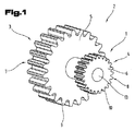
図1と2は、牽引手段駆動装置のためのマルチホィール2を形成するためのプリフォーム1を示している。この種の牽引手段駆動装置は、たとえばチェーンドライブまたはベルトドライブ(歯付きベルトドライブ)である。
1 and 2 show a
図1に示すプリフォーム1から形成されたマルチホィール2は、2つのシングルホィール3、4を有している。これらシングルホィール3、4の各々は、外周面7、8を備えたホィールボディ5、6を有しており、その外周面にわたって分配されて、牽引手段を噛合させるための歯9、10が配置されている。
The
マルチホィール2のこの実施形態において、2つのシングルホィール3、4は、異なる直径11、12(図2)を有している。もちろん、2つのシングルホィール3、4が同一の直径11、12を有することも、可能である。
In this embodiment of the
さらに、マルチホィール2が、2個のシングルホィール3、4のみを有するのではなく、2つより多い、たとえば3個、4個、5個などのマルチホィール3、4を有することも、可能である。その場合に、これらシングルホィール3、4が異なる直径を有し、あるいはすべての、あるいは2つより多いシングルホィール3、4が同一の直径を有する、可能性もある。好ましい実施形態において、マルチホィール2は、減少する直径11、12を備えた2、3のシングルホィール3、4を有し、その場合に最大の直径11を有するシングルホィール3の歯9と場合によってはそれに連続するシングルホィールが、チェーンドライブ用に形成されており、最小のシングルホィール4は、歯付きベルトを噛合させるために形成されている。
Furthermore, it is also possible for the multi-wheel 2 not to have only two
図1と2に明らかなように、マルチホィール2は、軸などを収容するための中央の孔13を有している。
As can be seen in FIGS. 1 and 2, the
好ましい実施形態において、マルチホィール2ないしプリフォーム1は、焼結金属ないし焼結金属合金から形成されている。これらは、たとえばアルミニウムベース、鉄ベース、銅ベース、マグネシウムベースで形成することができる。この種の焼結金属合金の例は、DIN V30910、PART4、第3ページから得られる。
In a preferred embodiment, the
当業者は焼結構成部品の基礎的な製造方法については知っているので、ここでは適当な文献を参照するよう指摘するにとどめる。特に、焼結構成部品の形成は、処理ステップ、場合によっては添加物および補助物質を有する、粉末の混合、圧粉体への粉末圧縮、圧粉体の焼結、場合によっては、焼結された構成部品の校正および/または再圧縮、を有している。 The person skilled in the art knows the basic method for manufacturing sintered components, and will only point out the appropriate literature here. In particular, the formation of sintered components is a processing step, optionally with additives and auxiliary substances, mixing powders, compressing powders into green compacts, sintering green compacts, and optionally sintered. Component calibration and / or recompression.
図3は、マルチホィール2のための歯輪郭の変形と最終形成のための第1の実施形態を示している。そのために、図3には、1個の歯10のみが示されている。特にその歯輪郭14が、以下においては歯付きベルトホィール輪郭15と称する、歯付きベルトのための輪郭として、以下においてチェーンホィール輪郭16と称する(破線で示す)、歯付きチェーンのための輪郭として、および粗輪郭17(一点鎖線で示す)として示されている。好ましくは粗輪郭17は、歯付きチェーンの噛合用の歯10を形成するための粗輪郭17として形成される。特にこれは、それぞれのプリフォーム1の焼結後の粗輪郭17である。
FIG. 3 shows a first embodiment for the deformation and final formation of the tooth profile for the
図3から明らかなように、歯側面18の領域における歯10の粗輪郭17は、歯付きチェーンを噛合させるための、出来上った歯10の歯側面厚み19よりも厚い。この粗輪郭17から歯10を最終形成するために、切削なしの変形が行われ、その場合に歯側面18の過剰寸法の領域から材料が、歯先面領域20内へ少なくとも部分的に移動される。同時に、この変形において、焼結材料の歯10の周面領域における圧縮も行うことができる。
As can be seen from FIG. 3, the
この粗輪郭17から歯付きベルトを噛合させるための歯10(歯付きベルトホィール輪郭15)を形成するために、変形は次のように行われる。すなわちまず、歯側面18の領域において粗輪郭17の過剰材料の少なくとも一部が、再び歯先領域20の方向へ移動され、もちろん−歯付きベルト噛合用の歯10は、原理的に歯付きチェーンの噛合用の歯10とは異なるとみなされるので−、この変形においては、歯先領域20に連続する歯側面領域21は、粗輪郭17に比較して幅広であって、場合によっては歯先領域20から材料がこの歯側面領域21へ移動されるので、従って歯の高さ22は、粗輪郭17の歯の高さよりも小さい。歯元領域において、歯付きベルトホィール輪郭15は、歯10の粗輪郭17と重なることができる。
In order to form the tooth 10 (toothed belt wheel contour 15) for meshing the toothed belt from the
ここで述べておくが、図示の実施例は、単に例としての特徴を有しているので、最終的な歯のジオメトリは、図示のものとは異なることができる。その限りにおいて、図3は単に、プリフォーム1(図1)からマルチホィール2を形成する原理の示しているに。 It should be noted that the illustrated embodiment has exemplary characteristics only, so that the final tooth geometry can be different from that shown. To that extent, FIG. 3 merely illustrates the principle of forming the multi-wheel 2 from the preform 1 (FIG. 1).
粗輪郭17は、図3に示す変形例においては、ほぼ伸開線状に形成されており、それによって変形および/または圧縮のために十分な材料が提供され、それによってそれぞれ要請に応じて、歯10を歯付きチェーン用または歯付きベルト用に形成することができる、という利点が得られる。その場合に、歯側面18の領域における過剰幅の最大の寸法は、歯10のチェーンホィール輪郭16の歯側面厚み19に関して、最大で25%の上限を有する領域から選択された値を有することができる(それぞれ左ないし右の過剰寸法)。この上限は、歯側面18の高さを超える過剰寸法が可変であって、それぞれ所望の歯のジオメトリに合わせることができる、と理解すべきである。もちろん、比較的細い、小さい歯10のための過剰寸法は、太くて大きい歯10のためとは異なる。完成した歯10の歯幾何配置全体にわたる比較において、過剰寸法は、図3の示唆から明らかなように、−25%から+25%、特に−20%から+20%の領域で変動することができる。
In the variant shown in FIG. 3, the
この実施形態においてプリフォーム1は、歯のジオメトリに関して対称に形成されているが、チェーンホィール輪郭16に関する粗輪郭17の過剰寸法の程度が、左の歯側面において右の歯側面に対して異なる、という可能性もある。
In this embodiment, the
シングルホィール3は、この変形例においてはチェーンホィールとして形成されているが、歯車であってもよい。このシングルホィールは、好ましくは、第2のシングルホィール4の歯10の変形の前に、その最終的な形状を有している。
The
図4には、本発明の実施形態が示されており、それにおいて歯付きベルトホィール輪郭15の歯10(実線)は、チェーンホィール輪郭16の歯10(破線)に比較してずっと小さい歯の高さ22を有している。この差23を可能にするために(たとえば、歯付きベルトホィール輪郭15は、チェーンホィール輪郭16の歯の高さ22の半分の大きさの歯の高さ22を有することができる)、歯先領域20において歯10の一部が切削で除去される。というのは、このように大きい減少は、もはや変形のみによってはもたらすことはできないからである。歯10の材料の除去は、たとえば、粗輪郭17の歯の高さ24(一点鎖線)まで削り取ることによって行われる。変形によって形成された、歯付きベルトホィール輪郭15の歯10は、変形後に、図3の実施形態に比較して、粗輪郭17の歯の高さ24に比較して大きい歯の高さ22を有しており、従って歯の高さだけに基づいて必要となるよりも多くの材料が除去される。従って、変形によって歯側面18の領域から材料が歯先の領域へ移動することができる。
FIG. 4 shows an embodiment of the invention in which the
図3からも、図4からも明らかなように、それぞれ変形後に、歯側面の急峻性と歯先の領域が変化される(急峻な歯側面と、歯付きチェーンドライブに比較して歯付きベルトドライブのための、より幅広の歯先)。 As can be seen from FIG. 3 and FIG. 4, after the deformation, the steepness of the tooth side surface and the region of the tooth tip are changed (the toothed belt compared to the steep tooth side surface and the toothed chain drive). Wider tooth tips for drive).
変形自体は、可塑的に、特に転造によって行われる。他方で、変形を分割された母型を用いて実施することも可能であって、その場合には、側方で然るべき粗輪郭17に分割された母型を介して圧力が加えられ、それによって然るべき領域への材料の押出しが実施される。変形自体は、熱間変形としても、冷間変形としても実施することができる。
The deformation itself takes place plastically, in particular by rolling . On the other hand, it is also possible to carry out the deformation using a divided matrix, in which case pressure is applied on the side via the divided matrix to the appropriate
従って、本発明に基づく方法を用いて、プリフォーム2**を用意し、そのプリフォームからそれぞれ必要に応じて少なくとも1つの歯車、歯付きベルトホィールまたはチェーンホィールを有するマルチホィール1**を形成することが可能であって、その場合にそれは、プリフォーム2から切削なしの変形によって形成される。従って、歯車またはチェーンホィールのための輪郭から歯付きベルトホィール、歯付きベルトホィールまたは歯車のための輪郭からチェーンホィール、あるいは歯付きベルトホィールまたはチェーンホィールのための輪郭から歯車を形成することができ、その場合に必要に応じてプリフォーム2の輪郭を、最初に考えられた歯車9、10のためのそれぞれの最終形状に切削なしで最終形成することもでき、従って歯車のためのプリフォーム2から歯車、チェーンホィールのためのプリフォーム2からチェーンホィール、あるいは歯付きベルトホィールのためのプリフォーム2から歯付きベルトホィールを形成することができる。
Thus, using the method according to the invention, a
実施例は、方法ないしプリフォーム1の可能な実施形態を示しており、その場合にここで注意すべきことは、本発明は、具体的に示されたその実施形態に限定されるものではなく、むしろ、個々に示された実施形態を互いに様々に組み合わせることも可能であって、この変形可能性は、本発明による技術的に取り扱うための教示に基づいて、この技術領域で活動する当業者の裁量の範囲にある、ということである。従って、説明した実施形態の個々の詳細を組み合わせることによって可能な、考えられるすべての実施形態も、保護範囲に含まれる。
The examples show possible embodiments of the method or
最後に念のために触れるが、プリフォーム1の構造を理解しやすくするために、このプリフォームないしその構成部分は、部分的に寸法通りでなく、かつ/または拡大および/または縮小して示されている。
Last but not least, in order to facilitate understanding of the structure of the
自立した発明的解決の基礎となる課題は、明細書から理解することができる。 The problem that forms the basis of an independent invention solution can be understood from the description.
特に、図1、2;3、4に示される個々の形態は、自立した、発明に基づく解決の対象を形成することができる。これに関する発明に基づく課題と解決が、これらの図の説明から理解される。 In particular, the individual forms shown in FIGS. 1, 2; 3, 4 can form self-supporting, inventive solutions. Problems and solutions based on the invention in this regard will be understood from the description of these figures.
1 プリフォーム
2 マルチホィール
3 シングルホィール
4 シングルホィール
5 ホィールボディ
6 ホィールボディ
7 周面
8 周面
9 歯
10 歯
11 直径
12 直径
13 孔
14 歯輪郭
15 歯付きベルトホィール輪郭
16 チェーンホィール輪郭
17 粗輪郭
18 歯側面
19 歯側面厚み
20 歯先領域
21 歯側面領域
22 歯の高さ
23 差
24 歯の高さ
DESCRIPTION OF
Claims (6)
前記マルチホィール(2)が少なくとも2つの並べて配置されたシングルホィール(3、4)を有し、
前記シングルホィールがそれぞれ、外周面(7、8)を備えたホィールボディ(5、6)を有し、前記外周面(7、8)に牽引手段を噛合させるための歯(9、10)が分配して配置されており、少なくとも2つのシングルホィール(3、4)の少なくとも1つがチェーンホィール、歯車または歯付きベルトホィールとして形成されていて、
チェーンホィール、歯車または歯付きベルトホィールが、粗輪郭(17)をもって形成されており、その場合に粗輪郭(17)の歯の厚みが、−軸方向に見て−出来上ったチェーンホィール、歯車、歯付きベルトホィールの最終輪郭の歯の厚みよりも厚くなっていて、その後、使用される牽引手段に従ってこの粗輪郭(17)が切削なしの変形、特に転造によって、完成した歯輪郭に変形される方法において、
チェーンホィールまたは歯車の粗輪郭(17)から歯付きベルトホィール輪郭を、あるいは、
歯車または歯付きベルトホィールの粗輪郭(17)からチェーンホィール輪郭を、あるいは、
歯付きベルトホィールまたはチェーンホィールの粗輪郭(17)から歯車輪郭を形成するようになっていて、この目的のために、歯(9、10)の歯面(18)の部分の粗輪郭(17)の余剰材料の少なくとも一部が歯先部分(20)の方向へ移動されることを特徴とする方法。 A method of forming an integral metal multi-wheel (2) for a traction means drive comprising:
The multi-wheel (2) has at least two side-by-side single wheels (3, 4);
Each of the single wheels has a wheel body (5, 6) having an outer peripheral surface (7, 8), and teeth (9, 10) for engaging traction means with the outer peripheral surface (7, 8). are arranged distributed to, be formed as at least one chain wheel, gear or toothed belt wheel of the at no less two single wheels (3,4),
A chain wheel, gear wheel or toothed belt wheel is formed with a rough contour (17), in which case the tooth thickness of the rough contour (17) is -as viewed in the axial direction--a finished chain wheel, Thickness of the tooth of the final contour of the gear wheel, toothed belt wheel is then thickened , and this rough contour (17) is then transformed into a finished tooth contour by deformation without cutting, in particular rolling , according to the traction means used In a modified method,
Chenhoi luma other or toothed belt wheel contour from the gear of the coarse contour (17),,
Teeth Kurumama others or chain wheel contour from coarse contour (17) of the toothed belt wheels,,
Toothed Berutohoi luma others they become due urchin that the chain wheel coarse contour (17) formed form a gear contour, for this purpose, crude part of the toothed surface of the (9, 10) (18) Method, characterized in that at least part of the surplus material of the contour (17) is moved in the direction of the tooth tip portion (20) .
少なくとも2つの並べて配置されたシングルホィール(3、4)を有し、
前記シングルホィールがそれぞれ、外周面(7、8)を備えたホィールボディ(5、6)を有し、牽引手段の噛合のための歯(9、10)が前記外周面(7、8)に分配して配置されており、2つのシングルホィールが、異なる牽引手段の噛合のために形成されるという条件で、2つのシングルホィール(3、4)がチェーンホィール、歯車または歯付きベルトホィールとして形成されていて、そして、2つのシングルホィールの少なくとも1つが、チェーンホィール、歯車または歯付きベルトホィールの粗輪郭(17)から切削なしの変形によって、特に転造によって、形成されているマルチホィールにおいて、
チェーンホィールまたは歯車の粗輪郭(17)から歯付きベルトホィール輪郭が、あるいは、
歯車または歯付きベルトホィールの粗輪郭(17)からチェーンホィール輪郭が、あるいは、
歯付きベルトホィールまたはチェーンホィールの粗輪郭(17)から歯車輪郭を形成するようになっていて、この目的のために、歯(9、10)の歯面(18)の部分の粗輪郭(17)の余剰材料の少なくとも一部が歯先部分(20)の方向へ移動される
ことを特徴とするマルチホィール。 An integral metal multi-wheel (2) for the traction means drive,
Having at least two side-by-side single wheels (3, 4),
Each of the single wheels has a wheel body (5, 6) with an outer peripheral surface (7, 8), and teeth (9, 10) for engaging the traction means are on the outer peripheral surface (7, 8). are arranged distributed to, form two single wheels are in the condition of being formed for engagement with different traction means, two single wheels (3, 4) chains wheels, as a gear or toothed belt wheel is in and, at least one of the two single wheels, chain wheels, by deformation without cutting from the gear or toothed belt wheel of the coarse contour (17), in a multi-wheel being in particular by rolling, forming,
Chenhoi luma other toothed belt wheel contour from the gear of the coarse contour (17) or,
Chain wheel contour from coarse contour (17) of the tooth Kurumama other toothed belt wheel is or,
Toothed Berutohoi luma others they become due urchin that the chain wheel coarse contour (17) formed form a gear contour, for this purpose, crude part of the toothed surface of the (9, 10) (18) Multi-wheel, characterized in that at least part of the surplus material of the contour (17) is moved in the direction of the tooth tip (20) .
Applications Claiming Priority (3)
| Application Number | Priority Date | Filing Date | Title |
|---|---|---|---|
| AT0177906A AT505150B1 (en) | 2006-10-24 | 2006-10-24 | multiple wheel |
| ATA1779/2006 | 2006-10-24 | ||
| PCT/AT2007/000489 WO2008049145A1 (en) | 2006-10-24 | 2007-10-22 | Method for the production of a one-piece metallic multiple wheel, preform for the production thereof, and multiple wheel |
Publications (3)
| Publication Number | Publication Date |
|---|---|
| JP2010507482A JP2010507482A (en) | 2010-03-11 |
| JP2010507482A5 JP2010507482A5 (en) | 2013-03-21 |
| JP5363326B2 true JP5363326B2 (en) | 2013-12-11 |
Family
ID=39106281
Family Applications (1)
| Application Number | Title | Priority Date | Filing Date |
|---|---|---|---|
| JP2009533608A Expired - Fee Related JP5363326B2 (en) | 2006-10-24 | 2007-10-22 | Multi wheel |
Country Status (9)
| Country | Link |
|---|---|
| US (1) | US8911313B2 (en) |
| EP (1) | EP2083956B1 (en) |
| JP (1) | JP5363326B2 (en) |
| CN (1) | CN101547758B (en) |
| AT (2) | AT505150B1 (en) |
| CA (1) | CA2667339A1 (en) |
| DE (1) | DE502007007017D1 (en) |
| ES (1) | ES2364861T3 (en) |
| WO (1) | WO2008049145A1 (en) |
Families Citing this family (4)
| Publication number | Priority date | Publication date | Assignee | Title |
|---|---|---|---|---|
| JP5688983B2 (en) * | 2011-01-28 | 2015-03-25 | アイダエンジニアリング株式会社 | Servo press system |
| US20160236750A1 (en) * | 2015-02-13 | 2016-08-18 | Shimano Inc. | Bicycle drive system |
| AT520531B1 (en) * | 2018-04-24 | 2019-05-15 | Miba Sinter Austria Gmbh | gear |
| CN114653941B (en) * | 2022-03-29 | 2022-12-02 | 西北有色金属研究院 | Powder metallurgy preparation method of nickel-titanium alloy gear |
Family Cites Families (23)
| Publication number | Priority date | Publication date | Assignee | Title |
|---|---|---|---|---|
| US3580029A (en) * | 1968-12-05 | 1971-05-25 | Lear Siegler Inc | Rolling chamfers on gear teeth |
| US3867751A (en) * | 1972-10-05 | 1975-02-25 | Formflo Ltd | Sintered blanks |
| US3874049A (en) * | 1973-04-13 | 1975-04-01 | Burdsall & Ward Co | Method of making a powdered metal part having a bearing surface |
| US4708912A (en) * | 1984-07-18 | 1987-11-24 | Sintermetallwerk Krebsoege Gmgh | Sintered metal body with at least one toothing |
| DD255492A1 (en) * | 1986-10-29 | 1988-04-06 | Textima Veb K | METHOD FOR THE PRODUCTION OF A DOUBLE GEAR FOR THE DRIVE OF A HOUSEHOLD WASTE TEMPERATURE |
| GB2250227B (en) * | 1990-10-08 | 1994-06-08 | Formflo Ltd | Gear wheels rolled from powder metal blanks |
| US5711187A (en) * | 1990-10-08 | 1998-01-27 | Formflo Ltd. | Gear wheels rolled from powder metal blanks and method of manufacture |
| CN2111154U (en) | 1991-12-12 | 1992-07-29 | 国营857厂 | Powder metallurgy gear blank |
| US5903815A (en) * | 1992-02-12 | 1999-05-11 | Icm/Krebsoge | Composite powdered metal component |
| JPH072258B2 (en) * | 1992-06-25 | 1995-01-18 | 本田技研工業株式会社 | Tooth profile sizing die |
| JP3448754B2 (en) * | 1995-08-23 | 2003-09-22 | 株式会社久保田鉄工所 | Gear rolling method and apparatus |
| US6134786A (en) * | 1999-01-29 | 2000-10-24 | Amsted Industries Incorporated | Method for improvement of involute and lead error in powder metal gears |
| IT1307199B1 (en) * | 1999-06-22 | 2001-10-29 | Mini Gears Spa | PROCESS FOR THE PRODUCTION OF TOOTHED WHEELS FROM SEMI-FINISHED PRODUCTS OBTAINED BY SINTERING METAL POWDERS |
| US6250123B1 (en) | 1999-09-20 | 2001-06-26 | Utica Enterprises, Inc. | Method, apparatus and rack for making power transmission member |
| GB2360825B (en) * | 2000-03-30 | 2004-11-17 | Formflo Ltd | Gear wheels roll formed from powder metal blanks |
| US6592809B1 (en) * | 2000-10-03 | 2003-07-15 | Keystone Investment Corporation | Method for forming powder metal gears |
| AT409466B (en) * | 2000-11-30 | 2002-08-26 | Miba Sintermetall Ag | METHOD AND DEVICE FOR PRODUCING A GEAR |
| DE10216524A1 (en) | 2002-04-15 | 2003-11-06 | Ebert Kettenspanntechnik Gmbh | Timing chain unit, comprising two chains guided across sprocket with two parallel rows of alternating teeth for adjustment of tension |
| JP2004074163A (en) * | 2002-08-09 | 2004-03-11 | Aisan Ind Co Ltd | Apparatus and method for rolling gear |
| JP2005344126A (en) * | 2002-10-04 | 2005-12-15 | Hitachi Powdered Metals Co Ltd | Sintered gear |
| DE10357979B4 (en) * | 2003-12-11 | 2006-10-05 | Sfs Intec Holding Ag | Torsion bar for use with belt retractors for safety belts |
| CN1319467C (en) | 2004-05-27 | 2007-06-06 | 张英梅 | Bee product of wild lotus |
| CN1644266A (en) | 2005-01-12 | 2005-07-27 | 刘宏伟 | Extruding method for teeth of gearing blanks |
-
2006
- 2006-10-24 AT AT0177906A patent/AT505150B1/en not_active IP Right Cessation
-
2007
- 2007-10-22 EP EP07815156A patent/EP2083956B1/en active Active
- 2007-10-22 JP JP2009533608A patent/JP5363326B2/en not_active Expired - Fee Related
- 2007-10-22 ES ES07815156T patent/ES2364861T3/en active Active
- 2007-10-22 DE DE502007007017T patent/DE502007007017D1/en active Active
- 2007-10-22 CA CA002667339A patent/CA2667339A1/en not_active Abandoned
- 2007-10-22 US US12/447,046 patent/US8911313B2/en not_active Expired - Fee Related
- 2007-10-22 WO PCT/AT2007/000489 patent/WO2008049145A1/en active Application Filing
- 2007-10-22 AT AT07815156T patent/ATE506127T1/en active
- 2007-10-22 CN CN200780039602.6A patent/CN101547758B/en not_active Expired - Fee Related
Also Published As
| Publication number | Publication date |
|---|---|
| AT505150A4 (en) | 2008-11-15 |
| ES2364861T3 (en) | 2011-09-15 |
| EP2083956B1 (en) | 2011-04-20 |
| US8911313B2 (en) | 2014-12-16 |
| EP2083956A1 (en) | 2009-08-05 |
| WO2008049145A1 (en) | 2008-05-02 |
| AT505150B1 (en) | 2008-11-15 |
| JP2010507482A (en) | 2010-03-11 |
| CN101547758A (en) | 2009-09-30 |
| DE502007007017D1 (en) | 2011-06-01 |
| US20100279807A1 (en) | 2010-11-04 |
| CA2667339A1 (en) | 2008-05-02 |
| ATE506127T1 (en) | 2011-05-15 |
| CN101547758B (en) | 2012-10-03 |
Similar Documents
| Publication | Publication Date | Title |
|---|---|---|
| US5711187A (en) | Gear wheels rolled from powder metal blanks and method of manufacture | |
| JP5363326B2 (en) | Multi wheel | |
| JP4409943B2 (en) | Apparatus and method for forming powder metal gears | |
| JP2005503486A5 (en) | ||
| US6730263B2 (en) | Process to manufacture a sintered part with a subsequent shaping of the green compact | |
| EP1268102B2 (en) | Method of manufacturing gear wheels roll formed from powder metal blanks | |
| EP2611560B1 (en) | Sintered gearwheel | |
| JP2004521743A (en) | Gear manufacturing method and apparatus | |
| JP2010507482A5 (en) | ||
| JPH0369844A (en) | Gear | |
| US20220390000A1 (en) | Method for producing a sintered component with a toothing | |
| JPWO2003091604A1 (en) | Gear product and method of manufacturing the gear product | |
| US6401562B1 (en) | Method for producing gear wheels from blanks obtained by sintering metal powders | |
| WO2008055275A1 (en) | Method for the powder-metallurgical production of a gearwheel | |
| CN104550605B (en) | Forging device | |
| JP3780438B2 (en) | Toothed member and manufacturing method thereof | |
| JP5951947B2 (en) | Machine component blank having a plurality of teeth and method of manufacturing the machine component | |
| JP5734944B2 (en) | Composite metal powder variable boundary gear and method | |
| JP3884424B2 (en) | Method for producing sintered part having teeth with back taper | |
| JP2004308769A (en) | Sintered gear | |
| UA47660C2 (en) | Matrix for pressing instrument profiles | |
| JP2006193786A (en) | Method for manufacturing sintered part having gear tooth with back taper | |
| JP2011089178A (en) | Re-pressurization method for sintered compact |
Legal Events
| Date | Code | Title | Description |
|---|---|---|---|
| A621 | Written request for application examination |
Free format text: JAPANESE INTERMEDIATE CODE: A621 Effective date: 20101018 |
|
| A977 | Report on retrieval |
Free format text: JAPANESE INTERMEDIATE CODE: A971007 Effective date: 20120725 |
|
| A131 | Notification of reasons for refusal |
Free format text: JAPANESE INTERMEDIATE CODE: A131 Effective date: 20120731 |
|
| A601 | Written request for extension of time |
Free format text: JAPANESE INTERMEDIATE CODE: A601 Effective date: 20120927 |
|
| A602 | Written permission of extension of time |
Free format text: JAPANESE INTERMEDIATE CODE: A602 Effective date: 20121004 |
|
| A524 | Written submission of copy of amendment under article 19 pct |
Free format text: JAPANESE INTERMEDIATE CODE: A524 Effective date: 20130130 |
|
| TRDD | Decision of grant or rejection written | ||
| A01 | Written decision to grant a patent or to grant a registration (utility model) |
Free format text: JAPANESE INTERMEDIATE CODE: A01 Effective date: 20130806 |
|
| A61 | First payment of annual fees (during grant procedure) |
Free format text: JAPANESE INTERMEDIATE CODE: A61 Effective date: 20130905 |
|
| R150 | Certificate of patent or registration of utility model |
Free format text: JAPANESE INTERMEDIATE CODE: R150 |
|
| LAPS | Cancellation because of no payment of annual fees |