JP5688983B2 - Servo press system - Google Patents
Servo press system Download PDFInfo
- Publication number
- JP5688983B2 JP5688983B2 JP2011016312A JP2011016312A JP5688983B2 JP 5688983 B2 JP5688983 B2 JP 5688983B2 JP 2011016312 A JP2011016312 A JP 2011016312A JP 2011016312 A JP2011016312 A JP 2011016312A JP 5688983 B2 JP5688983 B2 JP 5688983B2
- Authority
- JP
- Japan
- Prior art keywords
- command information
- operation command
- press
- transport
- servo
- Prior art date
- Legal status (The legal status is an assumption and is not a legal conclusion. Google has not performed a legal analysis and makes no representation as to the accuracy of the status listed.)
- Active
Links
- 230000033001 locomotion Effects 0.000 claims description 93
- 238000012546 transfer Methods 0.000 claims description 42
- 238000009499 grossing Methods 0.000 claims description 19
- 238000006243 chemical reaction Methods 0.000 claims description 3
- 230000001419 dependent effect Effects 0.000 claims 1
- 230000032258 transport Effects 0.000 description 124
- 238000000034 method Methods 0.000 description 19
- 238000001514 detection method Methods 0.000 description 11
- 230000008859 change Effects 0.000 description 6
- 230000001360 synchronised effect Effects 0.000 description 5
- 230000007246 mechanism Effects 0.000 description 4
- 238000007726 management method Methods 0.000 description 3
- 101000760620 Homo sapiens Cell adhesion molecule 1 Proteins 0.000 description 2
- 101000710013 Homo sapiens Reversion-inducing cysteine-rich protein with Kazal motifs Proteins 0.000 description 2
- 101000661816 Homo sapiens Suppression of tumorigenicity 18 protein Proteins 0.000 description 2
- 238000010276 construction Methods 0.000 description 2
- 230000007423 decrease Effects 0.000 description 2
- 238000010586 diagram Methods 0.000 description 2
- 238000006073 displacement reaction Methods 0.000 description 2
- 230000007274 generation of a signal involved in cell-cell signaling Effects 0.000 description 2
- 230000006872 improvement Effects 0.000 description 2
- 108090000237 interleukin-24 Proteins 0.000 description 2
- 230000003287 optical effect Effects 0.000 description 2
- 230000009467 reduction Effects 0.000 description 2
- 230000035939 shock Effects 0.000 description 2
- 101000911772 Homo sapiens Hsc70-interacting protein Proteins 0.000 description 1
- 101001139126 Homo sapiens Krueppel-like factor 6 Proteins 0.000 description 1
- 101000661807 Homo sapiens Suppressor of tumorigenicity 14 protein Proteins 0.000 description 1
- 230000005540 biological transmission Effects 0.000 description 1
- 230000000694 effects Effects 0.000 description 1
- 238000012840 feeding operation Methods 0.000 description 1
- 230000007257 malfunction Effects 0.000 description 1
- 239000000463 material Substances 0.000 description 1
- 238000012544 monitoring process Methods 0.000 description 1
- 230000008569 process Effects 0.000 description 1
- 238000012545 processing Methods 0.000 description 1
- 238000003672 processing method Methods 0.000 description 1
- 238000011160 research Methods 0.000 description 1
- 230000004043 responsiveness Effects 0.000 description 1
- 238000012360 testing method Methods 0.000 description 1
- 230000003245 working effect Effects 0.000 description 1
Images


Classifications
-
- B—PERFORMING OPERATIONS; TRANSPORTING
- B30—PRESSES
- B30B—PRESSES IN GENERAL
- B30B15/00—Details of, or accessories for, presses; Auxiliary measures in connection with pressing
- B30B15/14—Control arrangements for mechanically-driven presses
- B30B15/148—Electrical control arrangements
-
- B—PERFORMING OPERATIONS; TRANSPORTING
- B21—MECHANICAL METAL-WORKING WITHOUT ESSENTIALLY REMOVING MATERIAL; PUNCHING METAL
- B21D—WORKING OR PROCESSING OF SHEET METAL OR METAL TUBES, RODS OR PROFILES WITHOUT ESSENTIALLY REMOVING MATERIAL; PUNCHING METAL
- B21D43/00—Feeding, positioning or storing devices combined with, or arranged in, or specially adapted for use in connection with, apparatus for working or processing sheet metal, metal tubes or metal profiles; Associations therewith of cutting devices
- B21D43/02—Advancing work in relation to the stroke of the die or tool
- B21D43/04—Advancing work in relation to the stroke of the die or tool by means in mechanical engagement with the work
- B21D43/05—Advancing work in relation to the stroke of the die or tool by means in mechanical engagement with the work specially adapted for multi-stage presses
-
- B—PERFORMING OPERATIONS; TRANSPORTING
- B30—PRESSES
- B30B—PRESSES IN GENERAL
- B30B1/00—Presses, using a press ram, characterised by the features of the drive therefor, pressure being transmitted directly, or through simple thrust or tension members only, to the press ram or platen
- B30B1/26—Presses, using a press ram, characterised by the features of the drive therefor, pressure being transmitted directly, or through simple thrust or tension members only, to the press ram or platen by cams, eccentrics, or cranks
- B30B1/266—Drive systems for the cam, eccentric or crank axis
Landscapes
- Engineering & Computer Science (AREA)
- Mechanical Engineering (AREA)
- Control Of Presses (AREA)
- Press Drives And Press Lines (AREA)
- Numerical Control (AREA)
Description
クランク軸を回転させてスライドを昇降させるサーボプレスとこのサーボプレスにワークを搬送するサーボ搬送装置とを備えたサーボプレスシステムに関する。 The present invention relates to a servo press system including a servo press that rotates a crankshaft to raise and lower a slide and a servo transfer device that transfers a workpiece to the servo press.
プレス機械を代表例として、回転数一定のモータ、フライホイールを具備する従来プレスとサーボモータの回転制御によりスライド昇降させるサーボプレスに大別した場合、スライドモーションの相異は著しい。 When the press machine is a representative example, the difference in slide motion is significant when it is roughly divided into a conventional press equipped with a motor with a constant rotation speed and a servo press that slides up and down by rotation control of a servo motor.
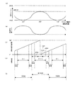
前者は、図6(B)に示すように、クランク軸の回転速度は一定であり、クランク機構を介した後のスライドモーションは図6(A)に示すように一定である。 In the former, as shown in FIG. 6 (B), the rotation speed of the crankshaft is constant, and the slide motion after passing through the crank mechanism is constant as shown in FIG. 6 (A).
後者は、スライドモーションを自由自在に設定することができる。すなわち、1サイクル中にスライドを低速で変位させ、また所定位置で停止させることもできる。クランク軸を任意の角度範囲内で往復回動運動させる、いわゆる振り子モーション(運動)を行わせることもできる。したがって、プレス加工態様の多様性および生産性向上の点では、次の比較から、後者が勝ること明白である。 In the latter, slide motion can be set freely. That is, the slide can be displaced at a low speed during one cycle and stopped at a predetermined position. It is also possible to perform a so-called pendulum motion (movement) in which the crankshaft is reciprocally rotated within an arbitrary angle range. Therefore, it is clear from the following comparison that the latter is superior in terms of diversity of press working modes and productivity improvement.
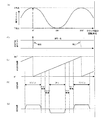
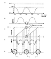
つまり、上記振り子モーションによるプレス運転は、図7(A)に示すように、クランク軸の回転角度を例えば60°〜180°〜300°の範囲で往復運動させる。クランク軸の回転速度は、図7(B)に示すようになる。回転角度60°、300°で、スライド位置は上限位置である。この上限位置は、回転角度が0°、360°における位置(上死点位置)よりも低い。つまり、回転角度300°〜360°〜60°間の無駄な回転運動(回転時間)を省くことができるから、回転角度180°(下死点位置)におけるプレス加工回数を増大(サイクルタイムを短縮)することができる。 That is, in the press operation by the pendulum motion, as shown in FIG. 7A, the rotation angle of the crankshaft is reciprocated within a range of 60 ° to 180 ° to 300 °, for example. The rotational speed of the crankshaft is as shown in FIG. At the rotation angles of 60 ° and 300 °, the slide position is the upper limit position. This upper limit position is lower than the position (top dead center position) at a rotation angle of 0 ° and 360 °. In other words, useless rotational movement (rotation time) between rotation angles of 300 ° to 360 ° to 60 ° can be eliminated, so the number of press workings at a rotation angle of 180 ° (bottom dead center position) is increased (cycle time is shortened). )can do.
ところで、サーボプレスの一層の普及拡大を図るには、運用上の実際問題をクリアーすることが大事である。実際問題の一つは、従来プレスに比較してスライド位置とクランク軸の回転角度との相対関係の把握が難しいことである。例えば、図6(A)に示す回転角度0°(360°)においてスライド位置は上限位置(上死点位置)であると長年に渡り認識していた者にとって、図7(A)の如く、上限位置は回転角度が60°および300°であるときの位置であり、その値は図6(A)に示す上死点位置(値)とは異なる低い位置(値)である。また、プレス運転中に回転角度が0°(360°)になることは無い。さらに、複数の回転角度においてスライド位置が同である場合が生じ得る。これらに関する事項を直感的に理解することは相当困難である。
By the way, it is important to clear actual operational problems in order to further increase the spread of servo presses. One of the actual problems is that it is difficult to grasp the relative relationship between the slide position and the rotation angle of the crankshaft as compared with the conventional press. For example, for those who have long recognized that the slide position is the upper limit position (top dead center position) at the
かくして、スライドモーション自体の設定作業、設定スライドモーションに対応するタイミング信号や同期信号の発生位置の設定作業や、ダイハイト調整作業が面倒で作業性が低下する。他の従来プレス(スライド駆動機構が例えば上下直動構造である。)に慣れた者にとっては、一段と面倒で作業ミスも発生し易い。 Thus, the work for setting the slide motion itself, the work for setting the timing signal and the generation position of the synchronization signal corresponding to the set slide motion, and the work for adjusting the die height are troublesome and workability is lowered. For those who are accustomed to other conventional presses (for example, the slide drive mechanism has a vertical linear motion structure), it is much more cumbersome and a work mistake is likely to occur.
この点に関しては、いわゆる仮想回転角度という概念を導入した改善策が提案(例えば、特許文献1、特許文献2)されている。特許文献1は、スライドモーションの1ストロークを360°に換算しかつ下死点を180°として分配換算したものを表示可能に形成し、仮想回転角度で表示されたモーションカーブ上でタイミング設定変更等をできるようにしたものである。特許文献2は、スライド位置を仮想クランク角度に換算して表示する。また、検出したスライド位置に対応する仮想回転角度を外部機器に出力するように形成されている。 With regard to this point, an improvement measure that introduces the concept of a so-called virtual rotation angle has been proposed (for example, Patent Document 1 and Patent Document 2). Patent Document 1 forms a slide motion that is converted into 360 ° and distributed and converted at a bottom dead center of 180 °, and changes timing settings on a motion curve displayed at a virtual rotation angle. It is made to be able to. Japanese Patent Application Laid-Open No. 2004-228561 displays the slide position by converting it into a virtual crank angle. Further, the virtual rotation angle corresponding to the detected slide position is output to the external device.
ところで、一層の生産性向上を図るにはプレス速度の一段の高速運転が必要である。と同時に、干渉発生を確実に回避できなければならない。干渉問題は、プレス運転中におけるプレス側構成要素(部位)と搬送装置側要素(部位)との相対位置関係であるから、プレスと搬送装置との同期運転が重要である。 By the way, in order to further improve productivity, it is necessary to operate at a high speed that is one step of the press speed. At the same time, it must be possible to reliably avoid interference. Since the interference problem is a relative positional relationship between the press-side component (part) and the transport device-side element (part) during the press operation, synchronous operation between the press and the transport device is important.
ここに、サーボプレスシステムの制御方式に関し、個別制御方式は、プレスと搬送装置とを別個に制御する方式なので、運転高速化および干渉回避のいずれの点からも問題が多い。マスタースレーブ制御方式は、プレス側から検出した信号を搬送装置側に入力して搬送装置を追従同期運転させる。総括管理制御方式は、同一信号に基づきプレスと搬送装置とを同期並行運転させる。どの方式を採用するかは恣意的である。生産性を重視するか、干渉回避を重視するかによって選択される場合が多い。 Here, regarding the control method of the servo press system, since the individual control method is a method of separately controlling the press and the conveying device, there are many problems in terms of both high speed operation and avoidance of interference. In the master-slave control method, a signal detected from the press side is input to the conveying device side to cause the conveying device to follow and synchronize. In the general management control method, the press and the conveying device are operated synchronously and in parallel based on the same signal. Which method is adopted is arbitrary. In many cases, the selection is made depending on whether productivity is important or interference avoidance is important.
いずれのシステム制御方式を採るにしても、生産性向上の観点からは上記振り子モーションによる運転高速化が有効である。干渉回避の観点からすると、運転中のプレス側部位の実際の挙動との関係において、搬送装置を運転させたいという要求は強い。 Regardless of which system control method is employed, speeding up of the operation by the pendulum motion is effective from the viewpoint of improving productivity. From the viewpoint of avoiding interference, there is a strong demand for operating the transport device in relation to the actual behavior of the press side part during operation.
さらに、同期信号の検出方法、検出個所、検出器の取付場所、信号生成回路方式などは、多岐に渡る。搬送装置の構造、剛性、慣性の大きさ等々も種々である。かくして、サーボプレスシステムの普及拡大に伴う運用の実際において、予期せぬ状態が発生することがある。例えば、搬送装置との同期運転が一時的に不安定になり、運転停止となり、さらには機器変形や破損を引き起こす場合も生じ得る。 Furthermore, there are a wide variety of synchronization signal detection methods, detection locations, detector mounting locations, signal generation circuit systems, and the like. The structure, rigidity, magnitude of inertia, etc. of the conveying device are various. Thus, an unexpected state may occur in the actual operation accompanying the widespread use of the servo press system. For example, the synchronous operation with the transport device becomes unstable temporarily, the operation is stopped, and further, the device may be deformed or damaged.
本発明の目的は、高い生産性と確実な干渉回避を担保しつつ円滑な運転ができるサーボプレスシステムを提供することにある。 An object of the present invention is to provide a servo press system capable of smooth operation while ensuring high productivity and reliable interference avoidance.
出願人の試験・研究によると、上記問題は振り子モーションによる運転の際に発生する蓋然性が高いと確信する。 According to the applicant's tests and research, the above problem is highly likely to occur when driving with pendulum motion.
すなわち、慣れ親しんだ従来プレスの場合は、図6(A)〜(E)に示す如く、クランク軸の回転速度は一定であり、スライドモーションが一定である。そして、搬送運転指令信号を1サイクル(0°〜360°)ごとに更新しつつ常時出力すれば、所定の一定速度で安定した搬送動作(アドバンス動作等)を行わせることができる。立上げ、立ち下げの搬送速度コントロールも円滑で搬送装置側に無理な負担を掛けることがない。 That is, in the case of a conventional press that is familiar, the rotational speed of the crankshaft is constant and the slide motion is constant, as shown in FIGS. If the transfer operation command signal is constantly output while being updated every cycle (0 ° to 360 °), a stable transfer operation (advanced operation or the like) can be performed at a predetermined constant speed. The conveyance speed control for starting up and falling down is smooth and does not place an excessive burden on the conveying device.
しかるに、サーボプレスでかつ振り子モーションの場合は、固有の技術事項(回転方向反転時にプレス構成要素は一時停止する。その前後に極めて停止に近い状態がある。)が存在する。かくして、同期信号の検出方法、検出個所、検出器の取付場所、信号生成回路方式などの組合せによっては、円滑運転が阻害される事態が発生する。 However, in the case of a servo press and a pendulum motion, there is an inherent technical matter (the press components are temporarily stopped when the direction of rotation is reversed. There are very close states before and after that). Thus, depending on the combination of the synchronization signal detection method, detection location, detector mounting location, signal generation circuit method, etc., a situation in which smooth operation is hindered may occur.
例えば、同期信号の検出個所をプレス構成部位(例えば、スライド位置、サーボモータ、クランク軸など)としかつ検出方法が当該部位の実際の挙動を捉える方法とするとともにその挙動(変化率)から信号生成する場合は、図7(A)、(B)に示すように回転方向反転時(60°、300°)にクランク軸は必ず一旦停止する。また、反転時を含むその前後の反転領域では限りなく速度ゼロ(0)に近い状態となる。クランク軸の回転停止は検出個所(例えば、サーボモータ)の停止に他ならない。 For example, the detection location of the synchronization signal is a press component part (for example, slide position, servo motor, crankshaft, etc.), and the detection method is a method that captures the actual behavior of the part and generates a signal from that behavior (rate of change) In this case, as shown in FIGS. 7A and 7B, the crankshaft always stops once when the rotation direction is reversed (60 °, 300 °). In addition, in the inversion areas before and after the inversion including the inversion time, the speed is almost as close to zero (0). Stopping rotation of the crankshaft is nothing but stopping of a detection location (for example, a servo motor).
したがって、図7(C)に示すように1サイクルごとに搬送指令信号を更新する回路方式[図6(C)の場合と同様な方式]を採用したとすると、検出個所が停止状態であるから検出信号に変化はない、つまり信号不連続となる。これは、プレス停止を意味することから、搬送停止命令と判断される場合がある。すると、搬送装置側では、図7(D)に示すように本来的には急速アドバンス動作されるべきところ、図7(E)に示す如くブレーキ動作となる。すなわち、一旦停止・再起動状態(Q)となるので、騒音発生や機器の変形・破損を招く虞がある。もとより、円滑な運転が阻害され生産性が低下する。 Therefore, if the circuit method of updating the conveyance command signal every cycle as shown in FIG. 7C [the same method as in the case of FIG. 6C] is adopted, the detection location is in the stopped state. There is no change in the detection signal, that is, the signal is discontinuous. Since this means a press stop, it may be determined as a conveyance stop command. Then, on the conveying apparatus side, as shown in FIG. 7 (D), a rapid advance operation should be originally performed, but a brake operation is performed as shown in FIG. 7 (E). That is, since it is temporarily stopped / restarted (Q), there is a possibility that noise may be generated or equipment may be deformed or damaged. Of course, smooth operation is hindered and productivity is lowered.
本発明は、干渉回避の観点から望まれる技術事項(プレス構成要素の実際挙動に依存して搬送装置との同期をとる。)を遵守しつつも、振り子モーションによるプレス運転時の固有的問題発生時には搬送装置の連続円滑運転を優先して実行可能に構築されたものである。換言すれば、本発明は、従来干渉発生はないものとして関心が薄くかつ見逃されていたプレス運転状態(スライドが上限位置乃至上死点位置にある。)において、振り子モーションの場合に限り発生する蓋然性が高くかつ発生すると被害が大きくなる問題点を、未然解決するものである。 While the present invention complies with technical matters desired from the viewpoint of avoiding interference (synchronization with the conveying device depending on the actual behavior of the press components), inherent problems occur during the press operation due to the pendulum motion. In some cases, it is constructed so as to give priority to continuous smooth operation of the transfer device. In other words, the present invention occurs only in the case of a pendulum motion in a press operation state (the slide is in the upper limit position or the top dead center position), which has been of little interest and has been overlooked since no interference has occurred in the past. It solves the problem that the probability is high and the damage will increase if it occurs.
詳しくは、請求項1の発明に係るサーボプレスシステムは、クランク軸を回転させてスライドを昇降させるサーボプレスとこのサーボプレスにワークを搬送するサーボ搬送装置とを備えたサーボプレスシステムにおいて、サーボプレスを振り子モーションでプレス運転可能に形成し、サーボ搬送装置に対する搬送運転指令情報をプレス構成要素の機械的動作状態に依存して生成される第1搬送運転指令情報とそれに依存しないで生成される第2搬送運転指令情報との2種類から形成し、振り子モーション中におけるプレス構成要素の現在動作状態が運動方向反転領域内での動作状態であるか否かを判別可能に形成し、プレス構成要素の現在動作状態が運動方向反転領域内での動作状態でないと判別された場合は第1搬送運転指令情報を利用し、運動方向反転領域内での動作状態であると判別されたときには前記第2搬送運転指令情報を利用してサーボ搬送装置を搬送運転可能に形成され、前記第1搬送運転指令情報が前記機械的動作状態である前記クランク軸の現在回転角度に依存した現在回転角度情報であり、かつ前記第2搬送運転指令情報がプレス速度情報を元
に創成されかつ連続性が担保された創成回転角度情報である。
Specifically, the servo press system according to the invention of claim 1 is a servo press system including a servo press that rotates a crankshaft to raise and lower a slide, and a servo transport device that transports a workpiece to the servo press. Is formed so as to be capable of press operation with a pendulum motion, and transport operation command information for the servo transport device is generated depending on the first transport operation command information generated depending on the mechanical operation state of the press component and the first generated independently of the first transport operation command information. 2 Formed from two types of transport operation command information, formed so as to be able to determine whether or not the current operation state of the press component in the pendulum motion is an operation state within the movement direction reversal region, When it is determined that the current operation state is not an operation state within the movement direction reversal region, the first transport operation command information is used. The second by using a transfer operation instruction information conveyed operable to form a servo transfer device, said first transfer operation instruction information the mechanical operation when it is judged that the operation state in the motion direction inversion area Current rotation angle information depending on the current rotation angle of the crankshaft in the state, and the second transport operation command information is based on the press speed information.
It is the creation rotation angle information that is created in the above and the continuity is ensured .
請求項2の発明に係るサーボプレスシステムは、クランク軸を回転させてスライドを昇降させるサーボプレスとこのサーボプレスにワークを搬送するサーボ搬送装置とを備えたサーボプレスシステムにおいて、サーボプレスをプレス運転指令情報に基づき振り子モーションでプレス運転可能に形成し、プレス構成要素の機械的動作状態に依存してサーボ搬送装置に対する搬送運転指令情報(第1搬送運転指令情報)を生成する第1搬送運転指令情報生成手段と、プレス構成要素の機械的動作状態に依存することなくサーボ搬送装置に対する搬送運転指令情報(第2搬送運転指令情報)を生成する第2搬送運転指令情報生成手段と、振り子モーション中におけるプレス構成要素の現在動作状態が予め設定された運動方向反転領域内での動作状態であるか否かを判別する反転領域内動作判別手段と、プレス構成要素の現在動作状態が設定運動方向反転領域内での動作状態でないと判別された場合は第1搬送運転指令情報をサーボ搬送装置に出力し、設定運動方向反転領域内での動作状態であると判別されたときには第2搬送運転指令情報をサーボ搬送装置に切替出力する搬送運転指令情報切替出力手段とを設け、クランク軸の振り子モーション中におけるプレス構成要素の現在動作状態が運動方向反転領域内での動作状態の場合にサーボ搬送装置の搬送運転動作の連続性を担保可能に形成され、前記第1搬送運転指令情報生成手段が前記機械的動作状態である前記クランク軸の現在回転角度に依存した現在回転角度情報を第1搬送運転指令情報として生成可能に形成され、かつ前記第2搬送運転指令情報生成手段がプレス速度情報を元に創成されかつ連続性が担保された創成回転角度情報を第2搬送運転指令情報として生成可能に形成されている。 According to a second aspect of the present invention, there is provided a servo press system comprising: a servo press that rotates a crankshaft to raise and lower a slide; and a servo transport system that transports a workpiece to the servo press. A first transport operation command that is formed so as to be capable of press operation with a pendulum motion based on the command information and generates transport operation command information (first transport operation command information) for the servo transport device depending on the mechanical operation state of the press components. Information generating means, second transport operation command information generating means for generating transport operation command information (second transport operation command information) for the servo transport device without depending on the mechanical operation state of the press component, and during pendulum motion The current operating state of the press component in the operation state in the direction of reversal of the direction of movement set in advance A reversing area operation discriminating means for discriminating whether or not there is, and if it is determined that the current operating state of the press component is not an operating state within the set motion direction reversing area, the first conveying operation command information is transmitted to the servo conveying apparatus. And a transfer operation command information switching output means for switching and outputting the second transfer operation command information to the servo transfer device when it is determined that the operation state is within the set movement direction reversal region. When the current operation state of the press component during the motion is an operation state in the movement direction reversal region, it is formed so as to ensure the continuity of the transport operation of the servo transport device , and the first transport operation command information generating means is Current rotation angle information depending on the current rotation angle of the crankshaft that is in the mechanical operation state is formed so as to be generated as first transport operation command information, and the second Feeding operation instruction information generating means is capable of generating form the created rotation angle information and continuity is created based on the press speed information is backed as the second transfer operation instruction information.
請求項3の発明は、現在回転角度情報を第1仮想回転角度に変換可能かつ回転角度指令情報を第2仮想回転角度に変換可能に形成され、搬送運転指令情報切替出力手段が変換後の第1仮想回転角度および第2仮想回転角度を選択的に切替出力可能に形成されている。 The invention according to claim 3 is formed such that the current rotation angle information can be converted into the first virtual rotation angle and the rotation angle command information can be converted into the second virtual rotation angle, and the transfer operation command information switching output means is the first after the conversion. The first virtual rotation angle and the second virtual rotation angle are selectively switched and output.
請求項4の発明は、第1搬送運転指令情報生成手段が機械的動作状態であるスライドの現在位置に依存した第1搬送運転指令情報(現在スライド位置情報)を生成可能に形成され、かつ第2搬送運転指令情報生成手段がプレス速度情報を元に創成されかつ連続性が担保された第2搬送運転指令情報(創成回転角度情報)を生成可能に形成されている。 According to a fourth aspect of the present invention, the first transport operation command information generating means is configured to be capable of generating first transport operation command information (current slide position information) depending on the current position of the slide in the mechanical operation state, and 2 The conveyance operation command information generation means is formed based on the press speed information and is configured to be able to generate the second conveyance operation command information (generation rotation angle information) in which continuity is ensured.
請求項5の発明は、第1搬送運転指令情報および第2搬送運転指令情報の相互間の切替え途中に第1搬送運転指令情報および第2搬送運転指令情報の比率を変えて組合されたスムージング化搬送運転指令情報を生成可能な切替スムージング化手段を設け、搬送運転指令情報切替出力手段は該切替え途中に切替スムージング化手段で生成されたスムージング化搬送運転指令情報を搬送装置へ出力可能に形成されている。 The invention according to claim 5 is a smoothing method in which the ratio of the first transport operation command information and the second transport operation command information is changed during the switching between the first transport operation command information and the second transport operation command information. A switching smoothing means capable of generating the transport operation command information is provided, and the transport operation command information switching output means is configured to output the smoothed transport operation command information generated by the switching smoothing means during the switching to the transport device. ing.
請求項1の発明によれば、高い生産性と確実な干渉回避を担保しつつ円滑な運転ができるサーボプレスシステムを提供することができる。 According to the first aspect of the present invention, it is possible to provide a servo press system capable of smooth operation while ensuring high productivity and reliable interference avoidance.
請求項2の発明によれば、請求項1の発明の場合と同様な効果を奏することができることに加え、具現化が容易で、取扱いが簡単である。 According to the invention of claim 2, in addition to the effects similar to those of the invention of claim 1, it is easy to implement and easy to handle.
さらに、請求項1または2の発明によれば、第1および第2搬送運転指令情報の信頼性を向上できかつサーボ搬送装置とサーボプレスとの同期運転を一段と安定化できる。また、請求項3の発明によれば、各種の設定作業の安全性および確実性を向上でき、一段と取扱が容易で作業ミスもなくなる。 Furthermore, according to the first or second aspect of the invention, the reliability of the first and second transport operation command information can be improved, and the synchronous operation between the servo transport device and the servo press can be further stabilized. According to the invention of claim 3 , the safety and certainty of various setting operations can be improved, the handling is easier, and there are no work errors.
請求項4の発明によれば、請求項2の発明の場合と同様に第1および第2搬送運転指令情報の信頼性を向上できかつサーボ搬送装置とサーボプレスとの同期運転を一段と安定化できる。 According to the invention of claim 4 , as in the case of the invention of claim 2 , the reliability of the first and second transfer operation command information can be improved and the synchronous operation of the servo transfer device and the servo press can be further stabilized. .
さらに、請求項5の発明によれば、ワーク搬送運転の一層の円滑化を達成できる。 Furthermore, according to the invention of claim 5 , further smoothing of the workpiece transfer operation can be achieved.
以下、本発明を実施するための最良の形態について、図面を参照して詳細に説明する。 Hereinafter, the best mode for carrying out the present invention will be described in detail with reference to the drawings.
(第1の実施の形態)
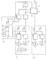
本サーボプレスシステムは、図1〜図3に示す如く、プレス運転指令情報(Sprs)に基づき振り子モーションでプレス運転可能に形成され、第1搬送運転指令情報生成手段(28)と第2搬送運転指令情報生成手段25と運動方向反転領域判別手段(34)と搬送運転指令情報切替出力手段40とを設け、クランク軸12の振り子モーション中におけるプレス構成要素(16)の現在動作状態(θpa)が運動方向反転領域(AR2)内での動作状態であるか否かに拘わらずサーボ搬送装置50の搬送運転動作の連続性を担保可能に形成されている。
(First embodiment)
As shown in FIGS. 1 to 3, the servo press system is formed so as to be capable of press operation with a pendulum motion based on press operation command information (Sprs), and includes a first transport operation command information generating means (28) and a second transport operation. The command information generating means 25, the moving direction reversal area discriminating means (34), and the conveyance operation command information switching output means 40 are provided, and the current operating state (θpa) of the press component (16) during the pendulum motion of the crankshaft 12 is Regardless of whether or not the operation state is within the movement direction reversal region (AR2), the continuity of the transport operation of the
また、この実施の形態では、各手段(31、34、38等)を設け、振り子モーションを規定するクランク角度を仮想回転角度に変換し、取扱い容易としている。 In this embodiment, each means (31, 34, 38, etc.) is provided to convert the crank angle defining the pendulum motion into a virtual rotation angle for easy handling.
図1において、サーボプレス10は、サーボモータ16の回転制御によりクランク軸12を回転させてスライド15を昇降させる。クランク軸12はコネクティングロッド13とともにクランク機構11を構成する。クランク軸12を一方向に1回転させれば、スライド位置を上死点位置(角度0°)から下死点位置(角度180°)に下降させ、さらに上死点位置(角度360°=0°)へ上昇させることができる。クランク機構11の特性として、クランク軸12を一定の回転速度で回転させた場合のスライドモーションは、図6(A)に示す如くサイン波形状カーブとなる。
In FIG. 1, the
サーボモータ16の回転軸には、エンコーダ18が連結されている。このエンコーダは、光学格子を利用する光電方式で角度相当信号θipを出力する。1回転当たり所定数パルス(例えば、100万パルス)を出力することができる。
An
現在プレス動作状態検出器(回転角度検出器)28は、エンコーダ18からの角度相当信号θipを入力として回転角度(クランク角度)信号θpaを生成出力する。現在プレス動作状態(現在動作状態)を表す回転角度信号θpaは、フィードバック信号Spaとしてプレスコントローラ27に入力される。
The current press operation state detector (rotation angle detector) 28 receives the angle equivalent signal θip from the
プレス制御部20は、プレス運転に必要な諸元(例えば、spm、振り子角度等)の設定や、記憶、制御および監視機能を持ち、サーボプレス全体管理を司る。プレス運転指令部21は、モーション選択器22で選択されたモーション(通常モーション、振り子モーションあるいは一時停止モーション等)、振り子角度設定器23で設定された振り子角度(例えば、60°、300°)およびspm設定器24を用いて設定されたプレス速度[spm…ストローク数(s)/1分(m)]に対応するスライドモーションを作成するとともに、作成された設定スライドモーションに従うプレス運転指令情報Spsをプレスコントローラ27に出力する。プレス運転が実行される。
The
プレス運転指令情報Spsは目標値であり、一般的・観念的には、位置信号、角度信号あるいは速度信号として選択形成されかつパルス信号として生成出力される。この第1の実施形態では、クランク軸12の回転角度を制御するためのプレス運転指令情報Spsは回転角度指令情報θpsの形で出力される。プレスコントローラ27において、目標値(Sps=θps)とフィードバック信号Spa(現在回転角度情報θpa)とが比較される。つまり、クローズループ角度制御系を形成する。
The press operation command information Sps is a target value, which is generally formed as a position signal, an angle signal, or a speed signal, and is generated and output as a pulse signal in general and notion. In the first embodiment, press operation command information Sps for controlling the rotation angle of the crankshaft 12 is output in the form of rotation angle command information θps. In the
かくして、振り子モーションを選択し、運動(回転)方向反転角度つまり振り子角度(例えば、60°および300°)を設定すれば、図3(A)、(B)[図7(A)、(B)の場合と同様。]に示すように、設定振り子モーション(2つの設定振り子角度60°、300°間でクランク軸12を往復回動変位させる。)でプレス運転することができる。2つの設定振り子角度は、下死点(180°)を中心に左右等角(上記の場合は、120°、120°)としなくてもよい。プレス速度は、設定spmで決まる。 Thus, if the pendulum motion is selected and the motion (rotation) direction reversal angle, that is, the pendulum angle (for example, 60 ° and 300 °) is set, FIG. 3 (A), (B) [FIG. 7 (A), (B ) Same as). ], The press operation can be performed with the set pendulum motion (the crankshaft 12 is reciprocally rotated between two set pendulum angles of 60 ° and 300 °). The two set pendulum angles may not be equal to the left and right equilateral angles (120 ° and 120 ° in the above case) with the bottom dead center (180 °) as the center. The press speed is determined by the setting spm.
なお、クランク軸12とサーボモータ(回転軸)16との間、サーボモータ(回転軸)16とエンコーダ18との間に、それぞれ減速機を設けてもよい。この際は、減速比に関する換算が必要である。
A reduction gear may be provided between the crankshaft 12 and the servomotor (rotating shaft) 16 and between the servomotor (rotating shaft) 16 and the
サーボ搬送装置50は、サーボプレス10にワーク(材料)を搬入し、プレス加工後のワーク(半製品乃至製品)を次段(後置のサーボプレス乃至ストックヤード)へ搬出する。このサーボ搬送装置50は、この実施形態の場合は、図3(D)に示すクランプ動作(ワーク把持)、リフト動作、アドバンス動作(ワーク搬送方向に移行)、ダウン動作、アンクランプ動作およびリターン動作(ワーク搬送方向と逆方向に移行)を所定のシーケンスに従って実行可能な3次元搬送方式である。なお、2次元搬送方式でも実施可能である。
The
3次元搬送方式におけるアドバンスおよびリターン動作用のみを示した図1において、サーボモータ56は図示しないアドバンス・リターン動作用駆動軸(フィーダ軸)を回転制御する。このサーボモータ56の回転軸には、エンコーダ58が連結されている。このエンコーダ58は、光学格子を利用する光電方式で角度相当信号θitを出力する。1回転当たり所定数パルスを出力することができる。
In FIG. 1 showing only the advance and return operations in the three-dimensional transport system, the
現在搬送動作状態検出器(回転角度検出器)68は、エンコーダ58からの角度相当信号θitを入力としてフィーダ軸の回転角度に対応する回転角度信号θtaを出力する。現在搬送動作状態(現在動作状態)を表す回転角度信号θtaは、フィードバック信号Staとして搬送コントローラ67に入力される。
The current conveyance operation state detector (rotation angle detector) 68 receives the angle equivalent signal θit from the
搬送コントローラ67には、目標値Stsとしての搬送運転指令情報Zが入力される。この搬送運転指令情報Zは、搬送運転(アドバンス動作、リターン動作)をプレス運転(スライド昇降動作)に同期させて行わせるための搬送運転指令信号であり、プレス側構成要素(部位)と搬送装置側構成要素(部位)との衝突(干渉)を回避するために重要である。
The conveyance operation command information Z as the target value Sts is input to the
ここに、干渉問題は、プレス側構成要素(部位)と搬送装置側構成要素(部位)との機械的相対位置の問題であるから、搬送運転指令情報Zはプレス運転中におけるプレス側構成要素(部位)の実際動作状態に対応する情報から生成するのが好ましい。具体的には、プレス構成要素(例えば、スライド15、クランク軸12、サーボモータ16等)やその部位の挙動、つまりサーボプレス10の機械的動作状態に依存して生成する。
Here, since the interference problem is a problem of the mechanical relative position between the press-side component (part) and the transport device-side component (part), the transport operation command information Z is the press-side component ( Preferably, it is generated from information corresponding to the actual operation state of the part. Specifically, it is generated depending on the press components (for example, the
この実施の形態では、精度的、経済的事情を考慮しつつ技術的特性(応答性および安定性)の観点から、搬送運転指令情報Zは、サーボモータ16に連結されたエンコーダ18の出力とされている。詳しくは、現在プレス動作状態検出器(回転角度検出器)28で信号処理生成されたクランク軸12の回転角度(現在動作状態)を表す回転角度信号θpaをもって搬送運転指令情報Zとしている。
In this embodiment, the conveyance operation command information Z is output from the
この搬送運転指令情報Z(=回転角度信号θpa)の信号形式としては、これを搬送コントローラ67に直接入力しても搬送運転制御可能に形成されているが、このままでは振り子モーションによるプレス運転が実行された場合の特殊事情(クランク軸12の反転時の一時停止状態)に伴う問題発生が懸念される。
The signal format of the conveyance operation command information Z (= rotation angle signal θpa) is formed so that the conveyance operation can be controlled even if it is directly input to the
すなわち、運動(回動)方向が反転し終わるまでには、クランク軸12は、物理的に必ず一旦は停止状態となる。そして、搬送運転指令情報Z(回転角度信号θpa)は、プレス構成要素(12)の機械的動作状態(回転角度変化)に依存して生成されるものと形成されている。したがって、クランク軸12の運動方向反転時には、図7(B)、(C)に示すように回転角度信号θpaが不連続となる。これは信号消失状態乃至プレス停止状態を意味する。つまり、サーボモータ56は、図3(B)に示す如く回転進行できず停止状態とみなされる。
In other words, the crankshaft 12 is physically stopped once before the movement (rotation) direction is reversed. The conveyance operation command information Z (rotation angle signal θpa) is generated depending on the mechanical operation state (rotation angle change) of the press component (12). Therefore, when the movement direction of the crankshaft 12 is reversed, the rotation angle signal θpa is discontinuous as shown in FIGS. 7B and 7C. This means a signal loss state or a press stop state. That is, the
一方、クランク軸12の運動方向反転時におけるスライド15は、図3(A)に示すように上限位置にある。かかる場合は干渉発生の心配が全く無い。そこで、アドバンス動作は、最高速度で連続搬送動作となるように形成されている。したがって、従来のサーボプレスシステムの場合と同様に、回転角度信号θpaの不連続化現象によりモータ急停止状態(ブレーキ状態)になってしまうと、搬送(アドバンス・リターン)装置50の大きな機械的慣性によって各所に過大な衝撃を与える。構成要素やそれら各部位の変形や破損を招く虞がある。大騒音ともなり得るばかりか、生産性を著しく低下させる。これら問題や不具合は、搬送速度を高速化すればするほど発生し易く、被害も大きくなる。
On the other hand, the
また、プレス側の回転角度検出器28、搬送装置側の搬送コントローラ67等が信号変化率を重視した信号処理方式とされている場合や、回転角度信号θpaの発信周波数が高くあるいは1パルス信号当たりの角度分解能が高くなればなる程に、上記問題が発生し易い。さらに、各手段の性能・特性やそれらの組合せ如何によって問題が起きる場合と起きないときがある。したがって、システム・装置の構築後や運用開始後に、発生してしまった問題の解決を図ることは、大きなリスクを負うことになる。つまり、事前に検討吟味して対処しておくべき課題であると理解される。
Further, when the
かくして、本発明では、上記問題解決のための各手段(28、25、34、40)を導入してサーボ搬送装置50の搬送運転動作の連続性を担保可能に形成してある。
Thus, in the present invention, each means (28, 25, 34, 40) for solving the above problems is introduced so that the continuity of the transport operation of the
第1搬送運転指令情報生成手段は、プレス構成要素の機械的動作状態に依存してサーボ搬送装置50に対する搬送運転指令情報(第1搬送運転指令情報)を生成する手段である。プレス構成要素の機械的動作状態に依存して情報を生成するとは、サーボプレス10の実際運転進行に伴うプレス構成要素の電気的、機械的動作のうちの機械的な動作状態を捉えてそれに対応する情報を生成するという限定的な意味である。実際のプレス運状態を元に搬送運転の同期性向上を企図する。
The first transport operation command information generating means is means for generating transport operation command information (first transport operation command information) for the
この実施の形態では、第1搬送運転指令情報生成手段を、上記した現在プレス動作状態検出器(回転角度検出器)28から形成し、機械的動作状態であるクランク軸12の現在回転角度θipに依存して第1搬送運転指令情報(現在回転角度情報θpa)を生成する。 In this embodiment, the first transport operation command information generating means is formed from the current press operation state detector (rotation angle detector) 28 described above, and the current rotation angle θip of the crankshaft 12 in the mechanical operation state is set. The first transport operation command information (current rotation angle information θpa) is generated depending on the above.
この第1搬送運転指令情報(現在回転角度情報θpa)は、第1仮想回転角度生成手段31により、図1、2,4,5に示す第1仮想回転角度Yに変換される。第1仮想回転角度生成手段31は、プレス制御部20において設定・記憶された振り子モーション用の左右動作角度θr、θl(例えば、60°、300°)を読み出して振り子範囲θlr(=θl−θr=240°)を算出しつつ、第1仮想回転角度Yを算出する。算出式は、Y=360°−(300°−X)×(360°/θlr)である。Xは、60°〜300°内の任意の角度である。
The first transport operation command information (current rotation angle information θpa) is converted into a first virtual rotation angle Y shown in FIGS. The first virtual rotation angle generation means 31 reads the pendulum motion left and right operating angles θr, θl (for example, 60 °, 300 °) set and stored in the
因みに、X=60、90,120,150,210,240,270,300°である場合は、Y=0,45,90,135,225,270,315,360°と換算される。もとより、X=180°で、Y=180°となる。 Incidentally, when X = 60, 90, 120, 150, 210, 240, 270, 300 °, it is converted to Y = 0, 45, 90, 135, 225, 270, 315, 360 °. Of course, when X = 180 °, Y = 180 °.
第2搬送運転指令情報生成手段は、プレス構成要素の機械的動作状態に依存することなくサーボ搬送装置50に対する搬送運転指令情報(第2搬送運転指令情報)を生成する手段である。第1搬送運転指令情報のように機械的動作状態に依存させないので、情報(信号)の連続性がある限りにおいて、プレス構成要素の電気的動作状態に依存して第2搬送運転指令情報を生成しても、格別に設けた信号発生器の出力信号を利用して第2搬送運転指令情報を生成可能に形成してもよい。
The second transport operation command information generating means is means for generating transport operation command information (second transport operation command information) for the
この実施の形態の場合、第2搬送運転指令情報生成手段25は、設定されたプレス速度情報(spm)を元に創成した創成回転角度情報(第2搬送運転指令情報)θspmを生成出力可能に形成されている。創成回転角度情報(第2搬送運転指令情報)θspmは、連続性が担保された信号である。 In the case of this embodiment, the second transport operation command information generating means 25 can generate and output the generated rotation angle information (second transport operation command information) θspm generated based on the set press speed information (spm). Is formed. The creation rotation angle information (second transport operation command information) θspm is a signal that ensures continuity.
例えば、設定プレス速度が30spmで、制御回路(25)の払出時間が1msの場合、クランク軸12の1回転当たりの払出回数は2000回であるから、1回の払出で0.18度(°)に相当する創成回転角度情報θspmを連続生成出力するように形成する。つまり、払出ごとの同期角度変化量は、0.18°である。 For example, if the set press speed is 30 spm and the payout time of the control circuit (25) is 1 ms, the number of payouts per revolution of the crankshaft 12 is 2000, so 0.18 degrees (° ) So as to continuously generate and output the creation rotation angle information θspm. That is, the amount of change in synchronization angle for each payout is 0.18 °.
すなわち、同期角度変化量(0.18°)を細分化する複数パルス信号を払出期間(図4のT=0〜T5)中にスキャン出力すれば、クランク軸12の運動方向反転時(停止時)においても連続する創成回転角度情報θspmを確実に発生させることができるわけである。創成回転角度情報θspmの1パルス当たりの回転角度(分解能)は、エンコーダ18および回転角度検出器28の性能上から出力し得る回転角度信号θpaの分解能と整合するように決められる。例えば、0.05°である。
In other words, if a plurality of pulse signals that subdivide the amount of change in synchronization angle (0.18 °) are scanned during the payout period (T = 0 to T5 in FIG. 4), the direction of movement of the crankshaft 12 is reversed (when stopped). ), It is possible to reliably generate continuous generation rotation angle information θspm. The rotation angle (resolution) per pulse of the generated rotation angle information θspm is determined so as to match the resolution of the rotation angle signal θpa that can be output from the performance of the
この第2搬送運転指令情報(創成回転角度情報θspm)は、第2仮想回転角度生成手段38により、図1、2,4,5に示す第2仮想回転角度Y’に変換される。図1の仮想回転時間算出手段34から出力される仮想回転時間Tがゼロ(0)となるごとにリセット・再生成される。つまり、図4に点線で示すように、1サイクル毎(例えば、300°)ごとに更新生成される。
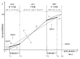
This second transport operation command information (creating rotation angle information θspm) is converted into a second virtual rotation angle Y ′ shown in FIGS. Each time the virtual rotation time T output from the virtual rotation
図4において、第2仮想回転角度Y’は、横軸の仮想回転時間Tが“0”から“T5”までかつ仮想回転角度が“0”から“360°”まで、点直線で示したように一定パルス間隔で連続出力される。対する第1仮想回転角度Yは振り子モーション運転に応じたものであるから、干渉域AR1内では実直線で示すようになるが非干渉域AR2内では曲線形状となる。この図4は主にスムージング化を説明するための図であることから、作図上、反転時(T=0、T=T5)およびその直近においても第1仮想回転角度Yが出力されているように見えるかもしれないが、実際には運動方向反転直近領域AR22でかつ反転時に極近いところでは不連続(出力停止状態)となっている。 In FIG. 4, the second virtual rotation angle Y ′ is indicated by a dotted line from the virtual rotation time T on the horizontal axis from “0” to “T5” and from the virtual rotation angle from “0” to “360 °”. Are continuously output at regular pulse intervals. On the other hand, since the first virtual rotation angle Y corresponds to the pendulum motion operation, the first virtual rotation angle Y is indicated by a solid line in the interference area AR1, but has a curved shape in the non-interference area AR2. Since FIG. 4 is a diagram mainly for explaining the smoothing, the first virtual rotation angle Y seems to be output at the time of reversal (T = 0, T = T5) and in the immediate vicinity in the drawing. Although it may appear, the region is actually discontinuous (output stopped state) in the region AR22 closest to the direction of motion reversal and very close to the direction of reversal.
この仮想回転時間算出手段34は、この実施の形態では、反転領域内動作判別手段(非干渉領域判別手段)をも形成する。なお、この仮想回転時間算出手段34、仮想回転角度切替出力機能およびスムージング化機能を説明するに先立ち、図3、図4に示す符号を説明して置く。
In this embodiment, the virtual rotation
AR1は、干渉領域(アンクランプ動作→リターン動作→クランプ動作)で、プレス構成要素と搬送装置構成要素との干渉が発生する虞の強い領域である。AR2は、非干渉領域(リフト動作→アドバンス動作→ダウン動作)で、プレス構成要素と搬送装置構成要素との干渉が発生する虞がない領域である。 AR1 is an interference region (unclamping operation → returning operation → clamping operation) and is a region where there is a strong possibility of interference between the press component and the conveying device component. AR2 is a non-interference region (lift operation → advance operation → down operation) and is a region where there is no possibility of interference between the press component and the transport device component.
この非干渉領域AR2は、運動方向反転領域であり、さらに細分化(AR21、AR22、AR23)される。運動方向反転直近領域AR22は、反転時(60°、300°)を中心としたクランク軸12(スライド15)の極低速運動領域である。AR21,AR23は、前・後スムージング領域である。 This non-interference area AR2 is a motion direction reversal area and is further subdivided (AR21, AR22, AR23). The motion direction reversal closest region AR22 is a very low speed motion region of the crankshaft 12 (slide 15) centered on reversal (60 °, 300 °). AR21 and AR23 are front and rear smoothing regions.
なお、図4は横軸が仮想回転時間(T)で縦軸が仮想回転角度(°)あるので、前スムージング化領域AR21、後スムージング化領域AR23は、図3(A)、(C)の場合と左右逆となる。 In FIG. 4, since the horizontal axis is the virtual rotation time (T) and the vertical axis is the virtual rotation angle (°), the pre-smoothing area AR21 and the post-smoothing area AR23 are shown in FIGS. This is the opposite of the case.
反転領域内動作判別手段(34)は、振り子モーション中におけるプレス構成要素(クランク軸12)の現在動作状態(現在プレス動作状態)が予め設定された運動方向反転領域(非干渉域)AR2内での動作状態であるか否かを判別する手段で、仮想回転時間算出手段34で算出された仮想回転時間Tの値をもって判別する時間管理判別方式である。図4において、仮想回転時間(T)が(T=0〜T2)および[T=T3〜T5(=0)]の場合に、運動方向反転領域(非干渉域)AR2内であると判別する。 The inversion region motion discriminating means (34) is in a motion direction inversion region (non-interference region) AR2 in which the current operation state (current press operation state) of the press component (crankshaft 12) during the pendulum motion is preset. This is a time management discriminating method that discriminates with the value of the virtual rotation time T calculated by the virtual rotation time calculation means 34 by means for determining whether or not the operating state is in the state of In FIG. 4, when the virtual rotation time (T) is (T = 0 to T2) and [T = T3 to T5 (= 0)], it is determined that it is in the motion direction reversal region (non-interference region) AR2. .
搬送運転指令情報切替出力手段40は、反転領域内動作判別手段(34)によってプレス構成要素(クランク軸12)の現在動作状態(θpa)が設定運動方向反転領域(非干渉域AR2)内での動作状態でないと判別された場合は、第1搬送運転指令情報(Y=Z)をサーボ搬送装置50(搬送コントローラ67)に出力する。 The conveyance operation command information switching output means 40 is configured so that the current operation state (θpa) of the press component (crankshaft 12) is within the set movement direction reversal area (non-interference area AR2) by the reversal area movement determination means (34). If it is determined that it is not in the operating state, the first transport operation command information (Y = Z) is output to the servo transport device 50 (transport controller 67).
具体的には、現在動作状態(θpa)に相当する第1仮想回転角度Yから算出された仮想回転時間Tの値により設定運動方向反転領域(AR2)内でないと判別された場合(つまり、干渉域AR1内である。)に、図4に実線で示す第1仮想回転角度Y(=Z)を、そのまま搬送コントローラ67に出力する(図5のST15)。 Specifically, when it is determined that it is not within the set motion direction reversal region (AR2) based on the value of the virtual rotation time T calculated from the first virtual rotation angle Y corresponding to the current operation state (θpa) (that is, interference) In the area AR1, the first virtual rotation angle Y (= Z) indicated by the solid line in FIG. 4 is output as it is to the transport controller 67 (ST15 in FIG. 5).
一方、反転領域内動作判別手段(34)によって設定運動方向反転領域(非干渉域AR2)内での動作状態であると判別されたときには、搬送運転指令情報切替出力手段40は、第2搬送運転指令情報(Y’=Z)をサーボ搬送装置50(67)に切替出力する。 On the other hand, when it is determined by the in-reverse-area operation determining means (34) that the operation state is within the set motion direction inversion area (non-interference area AR2), the transport operation command information switching output means 40 performs the second transport operation. The command information (Y ′ = Z) is switched and output to the servo transfer device 50 (67).
具体的には、第1仮想回転角度Yから算出された仮想回転時間Tの値により設定運動方向反転領域(AR2)内であると判別された場合は、図4に点線で示された第2仮想回転角度Y’(=Z)を、搬送コントローラ67に出力する(図5のST11、ST18)。 Specifically, when it is determined that it is within the set motion direction reversal region (AR2) from the value of the virtual rotation time T calculated from the first virtual rotation angle Y, the second indicated by the dotted line in FIG. The virtual rotation angle Y ′ (= Z) is output to the transport controller 67 (ST11 and ST18 in FIG. 5).
プレス構成要素の機械的動作状態に依存する第1仮想回転角度Yから連続性が担保された第2仮想回転角度Y’に切替える必要性は、本来的には、図3(C)、(D)に示す運動方向反転直近領域AR22だけで十分である。しかし、第1仮想回転角度Yから第2仮想回転角度Y’に切替える時点(図4のT3またはT4)および第2仮想回転角度Y’から第1仮想回転角度Yに切替える時点(図4のT1またはT2)において、両者Y、Y’間の角度相当信号値の差が常に小さいという保障はない。 The necessity of switching from the first virtual rotation angle Y depending on the mechanical operating state of the press component to the second virtual rotation angle Y ′ in which continuity is ensured is essentially shown in FIGS. Only the motion direction reversal nearest area AR22 shown in FIG. However, when switching from the first virtual rotation angle Y to the second virtual rotation angle Y ′ (T3 or T4 in FIG. 4) and when switching from the second virtual rotation angle Y ′ to the first virtual rotation angle Y (T1 in FIG. 4). Or, in T2), there is no guarantee that the difference in signal corresponding to the angle between Y and Y ′ is always small.
つまり、サーボプレス10、サーボ搬送装置50の構築内容や、運用状況等々によっては、搬送運転指令情報切替出力手段40の時間管理方式のみで切替出力制御したとすると、比較的に大きな電気的、機械的ショックが発生し、また円滑な運転が中断される虞があり得る。
That is, depending on the construction contents of the
そこで、搬送運転指令情報切替出力手段(仮想回転角度切替出力手段)40は、切替え途中に、切替スムージング化手段47で生成されたスムージング化搬送運転指令情報(Z)をサーボ搬送装置50へ出力可能に形成されている。
Therefore, the transport operation command information switching output means (virtual rotation angle switching output means) 40 can output the smoothed transport operation command information (Z) generated by the switching smoothing means 47 to the
切替スムージング化手段47は、第1搬送運転指令情報および第2搬送運転指令情報の相互間の切替え途中に、第1搬送運転指令情報(第1仮想回転角度Y)および第2搬送運転指令情報(第2仮想回転角度Y’)の比率を変えて組合されたスムージング化済である図4に太実線で示す搬送運転指令情報Zを生成出力する(図5のST13、ST17)。 The switching smoothing means 47 performs the first transfer operation command information (first virtual rotation angle Y) and the second transfer operation command information (in the middle of switching between the first transfer operation command information and the second transfer operation command information). The transport operation command information Z indicated by a thick solid line in FIG. 4 is generated and output (S13, ST17 in FIG. 5), which has been smoothed by changing the ratio of the second virtual rotation angle Y ′).
図4、図5において、仮想回転時間TがT1未満である場合(ST10でYES)は、点線で示す第2仮想回転角度Y’(=Z)が出力される(ST11)。従って、図4の時刻T=0で示された運動方向反転時とその前段階の直近低速運動域内において、第1仮想回転角度Yがゼロ(0)乃至限りなくゼロ(0)に近い値であるためにサーボモータ56が回転停止する虞が生じたとしても、第2仮想回転角度Y’(=Z)に切替済みであるから、これら問題を一掃することができる。
4 and 5, when the virtual rotation time T is less than T1 (YES in ST10), the second virtual rotation angle Y ′ (= Z) indicated by the dotted line is output (ST11). Accordingly, the first virtual rotation angle Y is zero (0) to a value close to zero (0) as much as possible at the time of reversal of the movement direction shown at time T = 0 in FIG. For this reason, even if the
仮想回転時間TがT4以上(およびT=T5)である場合(ST16でNO)も、点線で示す第2仮想回転角度Y’(=Z)が出力(ST18)されているので、問題はない。 Even when the virtual rotation time T is T4 or more (and T = T5) (NO in ST16), there is no problem because the second virtual rotation angle Y ′ (= Z) indicated by the dotted line is output (ST18). .
仮想回転時間TがT2を超えかつT3未満の場合(ST14でYES)は、干渉域AR1であるから、第1仮想回転角度Yが出力される(ST15)。 When the virtual rotation time T exceeds T2 and is less than T3 (YES in ST14), since it is the interference area AR1, the first virtual rotation angle Y is output (ST15).
仮想回転時間TがT1を超えかつT2未満の場合(ST12でYES)は、仮想回転時間Tの進行に伴って漸次減少する第2仮想回転角度Y’成分と漸次増大する第1仮想回転角度Y成分との組合せである太実線の仮想回転角度Zが出力される(ST13)。仮想回転時間TがT3を超えかつT4未満の場合(ST16でYES)は、仮想回転時間Tの進行に伴って漸次減少する第1仮想回転角度Y成分と漸次増大する第2仮想回転角度Y’成分との組合せである太実線の仮想回転角度Zが出力される(ST17)。 When the virtual rotation time T exceeds T1 and is less than T2 (YES in ST12), the second virtual rotation angle Y ′ component that gradually decreases with the progress of the virtual rotation time T and the first virtual rotation angle Y that gradually increases. The virtual solid rotation angle Z that is a combination with the components is output (ST13). When the virtual rotation time T exceeds T3 and is less than T4 (YES in ST16), the first virtual rotation angle Y component that gradually decreases with the progress of the virtual rotation time T and the second virtual rotation angle Y ′ that gradually increases. The virtual solid rotation angle Z that is a combination with the component is output (ST17).
切替時間Tcは、図1のスムージング化時間設定手段48を用いて設定変更される。すなわち、連続性が担保された第2仮想回転角度Y’で搬送運転させるべき運動方向反転直近領域AR22および前・後スムージング領域AR21,AR23の範囲を、当該システムおよび振り子モーション運転に最適範囲に設定した運用ができる。 The switching time Tc is changed by using the smoothing time setting means 48 in FIG. That is, the range of the motion direction reversal nearest area AR22 and the front / rear smoothing areas AR21 and AR23 to be transported at the second virtual rotation angle Y ′ in which continuity is ensured is set to the optimum range for the system and the pendulum motion operation. Can be operated.
しかして、この実施の形態によれば、振り子モーションでプレス運転可能なサーボプレス10とサーボ搬送装置50とを具備するサーボプレスシステムにおいて、搬送運転指令情報をプレス構成要素(16)の機械的動作状態に依存して生成される第1搬送運転指令情報(θpa)とそれに依存しないで生成される第2搬送運転指令情報(θspm)との2種類から形成し、プレス構成要素の現在動作状態が運動方向反転領域内での動作状態でない場合は第1搬送運転指令情報Yを利用し、動作状態であるときには第2搬送運転指令情報Y‘を利用してサーボ搬送装置50を搬送運転可能に形成されているので、高い生産性と確実な干渉回避を担保しつつ円滑な運転ができるサーボプレスシステムを提供することができる。
Thus, according to this embodiment, in the servo press system including the
第1搬送運転指令情報生成手段(28)と第2搬送運転指令情報生成手段25と反転領域内動作判別手段(34)と搬送運転指令情報切替出力手段40とを設け、クランク軸12の振り子モーション中におけるプレス構成要素の現在動作状態が運動方向反転領域内での動作状態であるか否かに拘わらずサーボ搬送装置50の搬送運転動作の連続性を担保可能に形成されているので、具現化が容易で、取扱いが簡単である。
The first transport operation command information generating means (28), the second transport operation command information generating means 25, the in-reverse region operation determining means (34), and the transport operation command information switching output means 40 are provided, and the pendulum motion of the crankshaft 12 is provided. The continuity of the transport operation of the
第1搬送運転指令情報生成手段(28)が現在回転角度情報θpaを第1搬送運転指令情報Yとして生成可能で、第2搬送運転指令情報生成手段25がプレス速度情報spmを元に創成されかつ連続性が担保された創成回転角度情報θspmを第2搬送運転指令情報Y‘として生成可能に形成されているので、第1および第2搬送運転指令情報の信頼性を向上できかつサーボ搬送装置50とサーボプレス10との同期運転を一段と安定化できる。
The first transport operation command information generating means (28) can generate the current rotation angle information θpa as the first transport operation command information Y, the second transport operation command information generating means 25 is created based on the press speed information spm, and Since the generation rotation angle information θspm in which continuity is ensured can be generated as the second transport operation command information Y ′, the reliability of the first and second transport operation command information can be improved and the
搬送運転指令情報切替出力手段40が現在回転角度情報θpaを変換した第1仮想回転角度Yおよび創成回転角度情報θspmを変換した第2仮想回転角度Y’を選択的に切替出力可能に形成されているので、各種の設定作業の安全性および確実性を向上でき、一段と取扱が容易で作業ミスもなくなる。 The conveyance operation command information switching output means 40 is configured to selectively switch and output the first virtual rotation angle Y converted from the current rotation angle information θpa and the second virtual rotation angle Y ′ converted from the generated rotation angle information θspm. As a result, the safety and certainty of various setting operations can be improved, handling is easier, and work errors are eliminated.
搬送運転指令情報切替出力手段40が切替え途中に切替スムージング化手段47で生成されたスムージング化搬送運転指令情報Zを搬送装置50へ出力可能に形成されているので、ワーク搬送運転の一層の円滑化を達成できる。
Since the transport operation command information switching output means 40 is configured to be able to output the smoothed transport operation command information Z generated by the switching smoothing means 47 during the switching to the
また、スムージング化時間設定手段48を設けて切替時間Tcの時間長を設定変更可能に形成されているので、当該構成および当該運転態様に対する適応性が広くかつ一段と取扱いがよい。 Further, since the smoothing time setting means 48 is provided so that the time length of the switching time Tc can be changed, the adaptability to the configuration and the operation mode is wide and the handling is better.
(第2の実施の形態)
この実施の形態の基本的構成・機能は第1の実施形態の場合(図1〜図5)と同様であるが、第1搬送運転指令情報生成手段が取扱う情報(信号)が第1の実施形態の場合とは異なる。
(Second Embodiment)
The basic configuration and function of this embodiment are the same as in the case of the first embodiment (FIGS. 1 to 5), but the information (signal) handled by the first transport operation command information generating means is the first embodiment. It is different from the case of form.
すなわち、プレスコントローラ27は、プレス運転指令情報Sps(スライド位置指令情報Pps)を目標値、スライド位置指令情報Ppaをフィードバック信号としてサーボモータ16を回転制御してスライド位置を昇降変位調整するクローズループ位置制御系を形成する。第1搬送運転指令情報(Sts)は、基本的には、スライド位置指令情報Ppaから形成されている。
That is, the
つまり、プレス運転指令部21は、第1の実施形態の場合(回転角度指令情報θps)と異なり、スライド位置指令情報Ppsを出力可能に形成されている。また、現在プレス動作状態検出器28は、第1の実施形態の場合(回転角度検出器)と異なり、スライド位置検出器として形成され、現在スライド位置情報Ppaを生成出力する。
That is, unlike the case of the first embodiment (rotation angle command information θps), the press
すなわち、第1搬送運転指令情報生成手段は、現在プレス動作状態検出器(スライド位置検出器)28から形成され、エンコーダ18から入力される現在回転角度θipを所定処理して、当該現在回転角度θipに対応する現在スライド位置情報Ppaを生成出力する。つまり、第1搬送運転指令情報生成手段(現在プレス動作状態検出器28)は、機械的動作状態であるスライド15の現在位置Pi(これに対応する回転角度θipとして検出される。)に依存した現在スライド位置情報Ppaを第1搬送運転指令情報として生成可能に形成されている。
In other words, the first transport operation command information generating means is formed from the current press operation state detector (slide position detector) 28, performs a predetermined process on the current rotation angle θip input from the
もっとも、第1搬送運転指令情報手段(28)は、スライド15に直接または間接的に関与して現在スライド位置Ppaを検出できればよいので、例えば、昇降するスライドの変位を光電検出する光電直動変位検出手段から形成するようにしてもよい。
However, the first transport operation command information means (28) only needs to be able to detect the current slide position Ppa by directly or indirectly participating in the
サーボ搬送装置50の搬送運転のみを考える場合は、目標値(現在スライド位置Ppa)を搬送コントローラ67に直接入力して搬送制御することができる。この際は、現在搬送状態検出器68を現在スライド位置Ppaに対応する現在搬送位置Ptaを出力可能に形成し、この現在搬送位置Ptaをフィードバック信号としても実施する。
When only the transport operation of the
しかし、この実施形態においても、振り子モーション角度を仮想回転角度に変換するので、第1の実施形態の場合と同様に、目標値Z(Sts)を搬送コントローラ67に入力し、かつ現在搬送状態検出器68からの現在搬送位置Ptaをフィードバック信号として搬送運転する。
However, also in this embodiment, the pendulum motion angle is converted into a virtual rotation angle, so that the target value Z (Sts) is input to the
第1仮想回転角度Yを生成出力する第1仮想回転角度生成手段31には、入力される第1搬送運転指令情報(現在スライド位置情報Ppa)をこれに対応する回転角度情報θpaに換算する機能が設けられている。第1実施形態の場合とは、この機能追加の点が異なる。 The first virtual rotation angle generation means 31 that generates and outputs the first virtual rotation angle Y has a function of converting the input first transport operation command information (current slide position information Ppa) into the corresponding rotation angle information θpa. Is provided. This function addition is different from the case of the first embodiment.
すなわち、第2仮想回転角度Y’を生成出力する第2仮想回転角度生成手段38、仮想回転角度算出手段(反転領域内動作判別手段)34、搬送運転指令情報切替出力手段40および切替スムージング化手段47の構成・機能は、第1の実施形態の場合と同様に形成されている。
That is, the second virtual rotation angle generation means 38 that generates and outputs the second virtual rotation angle Y ′, the virtual rotation angle calculation means (inversion region movement determination means) 34, the transport operation command information switching output means 40, and the switching smoothing means. The configuration /
しかして、この実施の形態によれば、第1の実施形態の場合と同様に、第1および第2搬送運転指令情報の信頼性を向上できかつサーボ搬送装置50とサーボプレス10との同期運転を一段と安定化できる。また、第1の実施形態の場合と比較して、スライド位置指令情報Spsおよび現在スライド位置情報Spaを採用するサーボプレス(システム)に対する導入が簡単である。
Thus, according to this embodiment, as in the case of the first embodiment, the reliability of the first and second transport operation command information can be improved and the synchronous operation of the
つまり、サーボプレス10およびサーボ搬送装置50の駆動制御上の信号を位置信号として構築し、各種設定等に関しては仮想回転角度方式を採用したいとする要請に応えるシステムを提供できる。
That is, it is possible to provide a system that meets the request to construct a signal on the drive control of the
10 サーボプレス
12 クランク軸
15 スライド
16 サーボモータ
18 エンコーダ
20 プレス制御部
21 プレス運転指令部
25 第2搬送運転指令情報生成手段
27 プレスコントローラ
28 現在プレス動作状態検出器(現在回転角度検出器、現在スライド位置検出器)
31 第1仮想回転角度生成手段
34 仮想回転時間算出手段(反転領域内判別手段)
38 第2仮想回転角度生成手段
40 搬送運転指令情報切替出力手段(運動方向反転領域判別手段)
47 切替スムージング化手段
50 サーボ搬送装置
56 サーボモータ
58 エンコーダ
67 搬送コントローラ
68 現在搬送動作状態検出器(現在搬送回転角度検出器、現在搬送位置検出器)
DESCRIPTION OF
31 First virtual rotation angle generation means 34 Virtual rotation time calculation means (inversion region discrimination means)
38 Second virtual rotation angle generating means 40 Conveyance operation command information switching output means (motion direction reversal region determining means)
47 Switching smoothing means 50
Claims (5)
前記サーボプレスを振り子モーションでプレス運転可能に形成し、
前記サーボ搬送装置に対する搬送運転指令情報をプレス構成要素の機械的動作状態に依存して生成される第1搬送運転指令情報とそれに依存しないで生成される第2搬送運転指令情報との2種類から形成し、
前記振り子モーション中におけるプレス構成要素の現在動作状態が運動方向反転領域内での動作であるか否かを判別可能に形成し、
プレス構成要素の現在動作状態が運動方向反転領域内での動作状態でないと判別された場合は前記第1搬送運転指令情報を利用し、運動方向反転領域内での動作状態であると判別されたときには前記第2搬送運転指令情報を利用して前記サーボ搬送装置を搬送運転可能に形成され、
前記第1搬送運転指令情報が前記機械的動作状態である前記クランク軸の現在回転角度に依存した現在回転角度情報であり、かつ前記第2搬送運転指令情報がプレス速度情報を元に創成されかつ連続性が担保された創成回転角度情報である、サーボプレスシステム。 In a servo press system including a servo press that rotates a crankshaft to raise and lower a slide and a servo transfer device that transfers a workpiece to the servo press,
The servo press is formed so as to be capable of press operation with a pendulum motion,
The transport operation command information for the servo transport device is classified into two types: first transport operation command information generated depending on the mechanical operation state of the press component and second transport operation command information generated independent of it. Forming,
It is possible to determine whether or not the current operation state of the press component in the pendulum motion is an operation in the movement direction reversal region,
When it is determined that the current operation state of the press component is not an operation state in the movement direction reversal region, it is determined that the press component is an operation state in the movement direction reversal region using the first conveyance operation command information. Sometimes it is formed so that the servo transport device can be transported using the second transport operation command information ,
The first conveyance operation command information is current rotation angle information dependent on a current rotation angle of the crankshaft in the mechanical operation state, and the second conveyance operation command information is created based on press speed information; Servo press system that is information on the creation rotation angle that ensures continuity .
前記サーボプレスをプレス運転指令情報に基づき振り子モーションでプレス運転可能に形成し、
プレス構成要素の機械的動作状態に依存して前記サーボ搬送装置に対する搬送運転指令情報としての第1搬送運転指令情報を生成する第1搬送運転指令情報生成手段と、
プレス構成要素の機械的動作状態に依存することなく前記サーボ搬送装置に対する搬送運転指令情報としての第2搬送運転指令情報を生成する第2搬送運転指令情報生成手段と、
前記振り子モーション中におけるプレス構成要素の現在動作状態が予め設定された運動方向反転領域内での動作状態であるか否かを判別する反転領域内動作判別手段と、
プレス構成要素の現在動作状態が設定運動方向反転領域内での動作状態でないと判別さ
れた場合は前記第1搬送運転指令情報を前記サーボ搬送装置に出力し、設定運動方向反転領域内での動作状態であると判別されたときには前記第2搬送運転指令情報を前記サーボ搬送装置に切替出力する搬送運転指令情報切替出力手段とを設け、
前記クランク軸の振り子モーション中におけるプレス構成要素の現在動作状態が運動方向反転領域内の動作状態の場合に前記サーボ搬送装置の搬送運転動作の連続性を担保可能に形成され、
前記第1搬送運転指令情報生成手段が前記機械的動作状態である前記クランク軸の現在回転角度に依存した現在回転角度情報を第1搬送運転指令情報として生成可能に形成され、かつ前記第2搬送運転指令情報生成手段がプレス速度情報を元に創成されかつ連続性が担保された創成回転角度情報を第2搬送運転指令情報として生成可能に形成されている、サーボプレスシステム。 In a servo press system including a servo press that rotates a crankshaft to raise and lower a slide and a servo transfer device that transfers a workpiece to the servo press,
The servo press is formed so as to be capable of press operation with a pendulum motion based on press operation command information,
First transport operation command information generating means for generating first transport operation command information as transport operation command information for the servo transport device depending on a mechanical operation state of a press component;
Second transport operation command information generating means for generating second transport operation command information as transport operation command information for the servo transport device without depending on the mechanical operation state of the press component;
Reversing region operation determining means for determining whether or not the current operating state of the press component in the pendulum motion is an operating state within a preset motion direction reversing region;
When it is determined that the current operation state of the press component is not an operation state within the set motion direction reversal region, the first transport operation command information is output to the servo transport device, and the operation within the set motion direction reversal region is performed. A transport operation command information switching output means for switching the second transport operation command information to the servo transport device when it is determined to be in a state;
When the current operating state of the press component in the pendulum motion of the crankshaft is an operating state in the movement direction reversal region, it is formed to ensure the continuity of the transport operation of the servo transport device ,
The first transport operation command information generating means is configured to be able to generate current rotation angle information depending on the current rotation angle of the crankshaft in the mechanical operation state as first transport operation command information, and the second transport A servo press system in which the operation command information generating means is generated based on the press speed information and is capable of generating, as second transport operation command information, the generated rotation angle information that ensures continuity .
前記現在回転角度情報を第1仮想回転角度に変換可能かつ前記創成回転角度情報を第2仮想回転角度に変換可能に形成され、前記搬送運転指令情報切替出力手段は変換後の第1仮想回転角度および第2仮想回転角度を選択的に切替出力可能に形成されている、サーボプレスシステム。 The servo press system according to claim 2 ,
The current rotation angle information can be converted into a first virtual rotation angle and the creation rotation angle information can be converted into a second virtual rotation angle. The transport operation command information switching output means can convert the first virtual rotation angle after conversion. And a servo press system configured to selectively switch and output the second virtual rotation angle.
前記第1搬送運転指令情報生成手段が前記機械的動作状態である前記スライドの現在位置に依存した現在スライド位置情報を第1搬送運転指令情報として生成可能に形成され、かつ第2搬送運転指令情報生成手段がプレス速度情報を元に創成されかつ連続性が担保された創成回転角度情報を第2搬送運転指令情報として生成可能に形成されている、サーボプレスシステム。 The servo press system according to claim 2 ,
The first transport operation command information generating means is configured to be able to generate current slide position information depending on the current position of the slide in the mechanical operation state as first transport operation command information, and second transport operation command information A servo press system in which the generating means is generated based on the press speed information and is configured to be able to generate generation rotation angle information in which continuity is ensured as second transport operation command information.
前記第1搬送運転指令情報および第2搬送運転指令情報の相互間の切替え途中に第1搬送運転指令情報および第2搬送運転指令情報の比率を変えて組合されたスムージング化搬送運転指令情報を生成可能な切替スムージング化手段を設け、
前記搬送運転指令情報切替出力手段は、該切替え途中に、切替スムージング化手段で生成されたスムージング化搬送運転指令情報を前記搬送装置へ出力可能に形成されている、サーボプレスシステム。 In the servo press system according to any one of claims 2 to 4 ,
In the middle of switching between the first transfer operation command information and the second transfer operation command information, the ratio of the first transfer operation command information and the second transfer operation command information is changed to generate smoothed transfer operation command information. Possible switching smoothing means,
The servo press system, wherein the transport operation command information switching output means is configured to be able to output the smoothed transport operation command information generated by the switching smoothing means to the transport device during the switching.
Priority Applications (4)
| Application Number | Priority Date | Filing Date | Title |
|---|---|---|---|
| JP2011016312A JP5688983B2 (en) | 2011-01-28 | 2011-01-28 | Servo press system |
| EP12152632.1A EP2481562B1 (en) | 2011-01-28 | 2012-01-26 | Servo press system |
| US13/359,948 US9126379B2 (en) | 2011-01-28 | 2012-01-27 | Servo press system |
| CN201210020535.6A CN102615852B (en) | 2011-01-28 | 2012-01-29 | Servo stamping system |
Applications Claiming Priority (1)
| Application Number | Priority Date | Filing Date | Title |
|---|---|---|---|
| JP2011016312A JP5688983B2 (en) | 2011-01-28 | 2011-01-28 | Servo press system |
Publications (2)
| Publication Number | Publication Date |
|---|---|
| JP2012152815A JP2012152815A (en) | 2012-08-16 |
| JP5688983B2 true JP5688983B2 (en) | 2015-03-25 |
Family
ID=45540802
Family Applications (1)
| Application Number | Title | Priority Date | Filing Date |
|---|---|---|---|
| JP2011016312A Active JP5688983B2 (en) | 2011-01-28 | 2011-01-28 | Servo press system |
Country Status (4)
| Country | Link |
|---|---|
| US (1) | US9126379B2 (en) |
| EP (1) | EP2481562B1 (en) |
| JP (1) | JP5688983B2 (en) |
| CN (1) | CN102615852B (en) |
Families Citing this family (7)
| Publication number | Priority date | Publication date | Assignee | Title |
|---|---|---|---|---|
| DE102013105468B4 (en) * | 2013-05-28 | 2015-10-01 | Schuler Pressen Gmbh | Method for controlling a press with variable gear ratio |
| CN103345268B (en) * | 2013-06-27 | 2016-09-07 | 苏州汇川技术有限公司 | The Full Closed-loop Position adjusting means of slider-crank mechanism and control method |
| EP2887655A1 (en) * | 2013-12-20 | 2015-06-24 | Swiss Timing Ltd. | Adaptive colour filter for digital sensor |
| CN109699070B (en) * | 2018-12-28 | 2021-01-01 | 湖南深拓智能设备股份有限公司 | Master and slave rotating equipment and synchronous control method thereof |
| US11146180B2 (en) | 2019-11-01 | 2021-10-12 | Rockwell Automation Technologies, Inc. | Linear and nonlinear dynamic bus control for AFE applications |
| US20250042117A1 (en) * | 2021-12-08 | 2025-02-06 | Bruderer Ag | Method for operating a punching press |
| CN115309126A (en) * | 2022-09-14 | 2022-11-08 | 扬力集团股份有限公司 | Servo automation multi-machine synchronous stamping production line control system and method |
Family Cites Families (33)
| Publication number | Priority date | Publication date | Assignee | Title |
|---|---|---|---|---|
| WO1991004116A1 (en) | 1989-09-22 | 1991-04-04 | Kabushiki Kaisha Komatsu Seisakusho | Control device for work feeder |
| JPH0571904U (en) | 1992-03-02 | 1993-09-28 | 福井機械株式会社 | Operation motion confirmation device for loaders and unloaders for press machines |
| JPH0655352A (en) | 1992-08-04 | 1994-03-01 | Shinko Electric Ind Co Ltd | Prepared hole position judging device |
| JP3528196B2 (en) | 1993-01-16 | 2004-05-17 | 株式会社安川電機 | Robot system synchronized with press machine |
| JPH0896025A (en) | 1994-07-28 | 1996-04-12 | Hitachi Ltd | Graphic processing method and apparatus |
| JPH08304494A (en) | 1995-04-28 | 1996-11-22 | Fujitsu Ltd | Electromagnetic field strength calculator |
| DE19616772A1 (en) | 1995-04-28 | 1996-10-31 | Fujitsu Ltd | Electromagnetic field strength calculation device |
| JP3773576B2 (en) | 1996-02-08 | 2006-05-10 | 株式会社小松製作所 | Transfer press |
| JP3766133B2 (en) | 1996-02-29 | 2006-04-12 | 富士通株式会社 | 3D circuit design support system for printed circuit boards |
| DE19642962A1 (en) | 1996-10-17 | 1998-04-23 | Mueller Weingarten Maschf | Hydraulic transfer press |
| JPH11245097A (en) | 1998-02-26 | 1999-09-14 | Aida Eng Ltd | Timing signal generating device of servo press |
| JP2000343294A (en) | 1999-06-02 | 2000-12-12 | Yamada Dobby Co Ltd | Transfer press line |
| JP2001062591A (en) * | 1999-08-24 | 2001-03-13 | Amada Co Ltd | Press machine |
| JP2002316298A (en) | 2001-04-18 | 2002-10-29 | Komatsu Ltd | Transfer press and slide driving method thereof |
| JP3784282B2 (en) | 2001-07-02 | 2006-06-07 | アイダエンジニアリング株式会社 | Interference check device for transfer press |
| JP4720034B2 (en) | 2001-07-05 | 2011-07-13 | 株式会社Ihi | Press transfer control device |
| JP3716779B2 (en) * | 2001-07-27 | 2005-11-16 | 村田機械株式会社 | Punch press |
| JP2003108212A (en) | 2001-10-02 | 2003-04-11 | Amada Co Ltd | Method and system for automating working with sheet metal |
| JP3860743B2 (en) | 2001-12-21 | 2006-12-20 | アイダエンジニアリング株式会社 | Press machine |
| JP2003191096A (en) | 2001-12-26 | 2003-07-08 | Aida Eng Ltd | Press machine system |
| JP3925844B2 (en) | 2002-02-22 | 2007-06-06 | アイダエンジニアリング株式会社 | Press machine |
| JP2003260530A (en) | 2002-03-07 | 2003-09-16 | Aida Eng Ltd | Pressing machine |
| JP2004058152A (en) * | 2002-06-05 | 2004-02-26 | Komatsu Ltd | Method of setting and displaying slide position of servo press, method of synchronizing with external peripheral device, and control device therefor |
| JP4342852B2 (en) * | 2003-07-01 | 2009-10-14 | アイダエンジニアリング株式会社 | Press machine |
| JP4301563B2 (en) * | 2004-03-19 | 2009-07-22 | アイダエンジニアリング株式会社 | Transfer press machine |
| JP4425043B2 (en) * | 2004-04-13 | 2010-03-03 | アイダエンジニアリング株式会社 | Transfer press operating method and transfer press machine |
| DE602004011916T2 (en) | 2004-07-10 | 2009-03-19 | Fagor, S.Coop, Mondragon | Device for the synchronized control of a number of machines, in particular presses |
| JP4783106B2 (en) | 2004-10-04 | 2011-09-28 | 株式会社小松製作所 | Inter-press synchronization controller |
| JP4507250B2 (en) * | 2004-10-29 | 2010-07-21 | アイダエンジニアリング株式会社 | Transfer press machine |
| ES2452022T3 (en) * | 2006-02-06 | 2014-03-31 | Abb Research Ltd. | Press line system and method |
| WO2007091964A2 (en) * | 2006-02-06 | 2007-08-16 | Abb Research Ltd. | Press line system and method |
| AT505150B1 (en) * | 2006-10-24 | 2008-11-15 | Miba Sinter Austria Gmbh | multiple wheel |
| JP4702901B2 (en) | 2008-07-07 | 2011-06-15 | アイダエンジニアリング株式会社 | Servo press line operation method and operation control device |
-
2011
- 2011-01-28 JP JP2011016312A patent/JP5688983B2/en active Active
-
2012
- 2012-01-26 EP EP12152632.1A patent/EP2481562B1/en active Active
- 2012-01-27 US US13/359,948 patent/US9126379B2/en not_active Expired - Fee Related
- 2012-01-29 CN CN201210020535.6A patent/CN102615852B/en not_active Expired - Fee Related
Also Published As
| Publication number | Publication date |
|---|---|
| EP2481562A2 (en) | 2012-08-01 |
| CN102615852B (en) | 2016-03-02 |
| JP2012152815A (en) | 2012-08-16 |
| EP2481562B1 (en) | 2019-08-21 |
| US20120192607A1 (en) | 2012-08-02 |
| US9126379B2 (en) | 2015-09-08 |
| CN102615852A (en) | 2012-08-01 |
| EP2481562A3 (en) | 2014-06-04 |
Similar Documents
| Publication | Publication Date | Title |
|---|---|---|
| JP5688983B2 (en) | Servo press system | |
| CN101052485B (en) | Transfer press machine | |
| KR101494117B1 (en) | Electric motor control system and communication method | |
| JP5647059B2 (en) | Tandem press line | |
| JP5665233B2 (en) | Servo transfer press system | |
| US8096233B2 (en) | Servo press line operation method and servo press line operation control device | |
| CN103640978B (en) | Tower machine operation control system and method | |
| JP5844774B2 (en) | Servo transfer feeder and control method of servo transfer feeder | |
| KR20080091211A (en) | Mechanical press drive system | |
| EP3444080B1 (en) | Actuator control system, actuator control method, information-processing program, and recording medium | |
| JP2009172648A (en) | Servo-press machine | |
| JP2005297010A (en) | Transfer press operating method and transfer press machine | |
| JP6629817B2 (en) | Control system and motor control method | |
| JP2006178832A (en) | Motor driving pulse output ic, and electronic cam control system | |
| JP7572452B2 (en) | Production Systems and Control Devices | |
| CN117945098A (en) | Conveying system and synchronous control method and device thereof | |
| JP4837928B2 (en) | Coil line device and control method thereof | |
| JP5596369B2 (en) | Positioning device and positioning method | |
| JPWO2014024215A1 (en) | Torque control device | |
| JP2022096797A (en) | Servo press machine and control method for servo press machine | |
| JP4525081B2 (en) | Tandem device using linear encoder | |
| TWM450911U (en) | Control device for dual electric machines | |
| JP4425237B2 (en) | Motor control device | |
| JP5054779B2 (en) | Transfer press equipment | |
| JP4301563B2 (en) | Transfer press machine |
Legal Events
| Date | Code | Title | Description |
|---|---|---|---|
| A621 | Written request for application examination |
Free format text: JAPANESE INTERMEDIATE CODE: A621 Effective date: 20130313 |
|
| A977 | Report on retrieval |
Free format text: JAPANESE INTERMEDIATE CODE: A971007 Effective date: 20140130 |
|
| A131 | Notification of reasons for refusal |
Free format text: JAPANESE INTERMEDIATE CODE: A131 Effective date: 20140205 |
|
| A521 | Written amendment |
Free format text: JAPANESE INTERMEDIATE CODE: A523 Effective date: 20140325 |
|
| A131 | Notification of reasons for refusal |
Free format text: JAPANESE INTERMEDIATE CODE: A131 Effective date: 20141001 |
|
| A521 | Written amendment |
Free format text: JAPANESE INTERMEDIATE CODE: A523 Effective date: 20141114 |
|
| TRDD | Decision of grant or rejection written | ||
| A01 | Written decision to grant a patent or to grant a registration (utility model) |
Free format text: JAPANESE INTERMEDIATE CODE: A01 Effective date: 20150121 |
|
| A61 | First payment of annual fees (during grant procedure) |
Free format text: JAPANESE INTERMEDIATE CODE: A61 Effective date: 20150127 |
|
| R150 | Certificate of patent or registration of utility model |
Ref document number: 5688983 Country of ref document: JP Free format text: JAPANESE INTERMEDIATE CODE: R150 |
|
| R250 | Receipt of annual fees |
Free format text: JAPANESE INTERMEDIATE CODE: R250 |
|
| R250 | Receipt of annual fees |
Free format text: JAPANESE INTERMEDIATE CODE: R250 |
|
| R250 | Receipt of annual fees |
Free format text: JAPANESE INTERMEDIATE CODE: R250 |
|
| R250 | Receipt of annual fees |
Free format text: JAPANESE INTERMEDIATE CODE: R250 |