JP5359121B2 - Display driving device and display device - Google Patents
Display driving device and display device Download PDFInfo
- Publication number
- JP5359121B2 JP5359121B2 JP2008217970A JP2008217970A JP5359121B2 JP 5359121 B2 JP5359121 B2 JP 5359121B2 JP 2008217970 A JP2008217970 A JP 2008217970A JP 2008217970 A JP2008217970 A JP 2008217970A JP 5359121 B2 JP5359121 B2 JP 5359121B2
- Authority
- JP
- Japan
- Prior art keywords
- voltage level
- voltage
- common
- signal
- vgl1
- Prior art date
- Legal status (The legal status is an assumption and is not a legal conclusion. Google has not performed a legal analysis and makes no representation as to the accuracy of the status listed.)
- Active
Links
Images


Abstract
Description
本発明は、所定のフレーム毎に共通電極の電圧レベルを変化させる表示駆動装置及び表示装置に関する。 The present invention relates to a display driving device and a display device that change a voltage level of a common electrode every predetermined frame.
液晶表示装置に用いられるドットマトリクス方式の表示パネルとして、単純マトリクス方式の表示パネルとアクティブマトリクス方式の表示パネルとが知られている。このうち、アクティブマトリクス方式の表示パネルにおいては、表示パネル上に複数の走査ラインと複数の信号ラインとをそれぞれ直交するように配置し、これら走査ラインと信号ラインとの交点近傍に薄膜トランジスタ(Thin Film Transistor:以下、TFTと記す)を介して画素電極と、さらに画素電極に対向するように共通電極と、を配し、画素電極と共通電極との間に液晶を充填することで表示画素を構成している。そして、走査ラインを介して入力された走査信号によって選択状態とされた表示画素に信号ラインから表示信号を印加する。また、共通電極にはコモン信号を印加する。このとき、表示画素を構成する液晶には表示信号とコモン信号との差に相当する電圧が印加され、これによって、液晶の配向状態を変化させて表示を行うようにしている。
As a dot matrix type display panel used in a liquid crystal display device, a simple matrix type display panel and an active matrix type display panel are known. Among them, in an active matrix display panel, a plurality of scanning lines and a plurality of signal lines are arranged on the display panel so as to be orthogonal to each other, and a thin film transistor (Thin Film) is formed in the vicinity of the intersection of the scanning lines and the signal lines. Transistor: hereinafter, constituting a pixel electrode through the referred to TFT), further arranged a common electrode so as to face the pixel electrode, and the display pixels by filling a liquid crystal between the pixel electrode and the common electrode doing. Then, a display signal is applied from the signal line to the display pixel selected by the scanning signal input through the scanning line. A common signal is applied to the common electrode. At this time, a voltage corresponding to the difference between the display signal and the common signal is applied to the liquid crystal composing the display pixel, thereby changing the alignment state of the liquid crystal for display.
ここで、長寿命化等の理由で、液晶の駆動には交流駆動が必須である。この交流駆動の手法として、例えば液晶に印加される電圧の極性をフレーム毎に反転させるフレーム反転駆動が知られている(例えば、特許文献1参照)。 Here, AC driving is essential for driving the liquid crystal for reasons such as extending the life. As this AC driving method, for example, frame inversion driving is known in which the polarity of the voltage applied to the liquid crystal is inverted for each frame (see, for example, Patent Document 1).
図11、図12(a)、図12(b)は、フレーム反転駆動時における印加電圧波形を示している。また、図13は、フレーム反転駆動時のモデル図を示している。 11, FIG. 12A and FIG. 12B show applied voltage waveforms during frame inversion driving. FIG. 13 shows a model diagram during frame inversion driving.
TFTに走査信号が印加されることにより、選択状態となった表示画素の画素電極に表示信号Vsが印加される。このとき、液晶には画素電極に印加された表示信号としての画素電極電位Vs’と共通電極に印加されているコモン信号Vcomとの差の電圧VLCDが印加されて表示が行われる。フレーム反転駆動においては、図11に示すように、共通電極に印加するコモン信号Vcomと表示信号Vsとの両方或いは一方の電圧レベルを、ある所定の中心電圧を中心としてフレーム毎に反転させるようにしている。
By applying the scanning signal to the TFT, the display signal Vs is applied to the pixel electrode of the display pixel that has been selected. At this time, the liquid crystal is applied with a voltage VLCD which is a difference between the pixel electrode potential Vs ′ as a display signal applied to the pixel electrode and the common signal Vcom applied to the common electrode, and display is performed. In the frame inversion driving, as shown in FIG. 11, both or one of the voltage level of the display signal Vs and the common signal Vcom applied to the common electrode, so as to reverse around a certain predetermined center voltage for each frame ing.
フレーム反転駆動の場合、図12(a)、図12(b)に示すように、次のフレーム期間に移行してコモン信号Vcomの極性が反転する際に、容量カップリング効果により画素電極電位Vs’がΔV2だけ変化する。このときの変化量ΔV2は、画素電極と共通電極との間に充填される液晶の等価容量をCLcd、液晶に印加される電圧を次のフレームまで保持しておくための補助容量の容量をCcs、TFTのゲート−ソース間に発生する寄生容量をCgs、コモン信号の電圧レベルの変化量、即ちコモン信号の振幅中心電圧に対して正極側のコモン電圧レベルVcomHと負極側のコモン電圧レベルVcomLとの差をVcomppとすると、下記式で表わされる。下記式で示すように、ΔV2は、TFTの寄生容量Cgsの影響によりVcomppよりも小さくなり、結果としてコモン信号Vcomの極性反転後の液晶に印加される電圧は極性反転前の液晶に印加される電圧VLCDよりもVcompp−ΔV2だけ小さくなる。
ΔV2=(CLcd+Ccs)×Vcompp/(Cgs+CLcd+Ccs)
ここで、液晶に印加される電圧がVcompp−ΔV2だけ小さくなる期間T1は、コモン信号Vcomの電圧極性が反転されてから、次のフレームにおいてTFTがオン状態となり、画素電極に表示信号Vsが再び書き込まれ画素電極電位Vs’が更新されるまでの間続く。このため、例えば、画面上部から画面下部に向けて走査を行うような液晶表示装置の場合、画面上部の表示画素になるほど1フレーム期間内で先にTFTがオン状態となるため液晶に印加される電圧が本来印加されるべき電圧VLCDよりもVcompp−ΔV2だけ小さくなる期間T1が短くなる。その一方で画面下部の表示画素になるほど液晶に印加される電圧が本来印加されるべき電圧VLCDよりもVcompp−ΔV2だけ小さくなる期間T1が長くなる。従って、画面上部の表示画素から順に画面下部の表示画素に向かって液晶に印加される実効電圧が小さくなり、各表示画素にたとえ同一の表示データに対応した表示信号を書き込んだ場合であっても、画面上部から画面下部にかけた輝度傾斜が発生してしまう。
In the case of frame inversion driving, as shown in FIGS. 12A and 12B, when the polarity of the common signal Vcom is inverted after the transition to the next frame period, the pixel electrode potential Vs is caused by the capacitive coupling effect. 'Changes by ΔV2. The amount of change ΔV2 at this time is CLcd as the equivalent capacitance of the liquid crystal filled between the pixel electrode and the common electrode, and Ccs as the capacitance of the auxiliary capacitance for holding the voltage applied to the liquid crystal until the next frame. The parasitic capacitance generated between the gate and the source of the TFT is Cgs, the amount of change in the voltage level of the common signal, that is, the common voltage level VcomH on the positive side and the common voltage level VcomL on the negative side with respect to the amplitude center voltage of the common signal. When the difference of Vcomp is Vcompp, it is expressed by the following equation. As shown in the following formula, ΔV2 becomes smaller than Vcompp due to the influence of the parasitic capacitance Cgs of the TFT, and as a result, the voltage applied to the liquid crystal after the polarity inversion of the common signal Vcom is applied to the liquid crystal before the polarity inversion. The voltage VLCD is smaller than the voltage VLCD by Vcompp−ΔV2.
ΔV2 = (CLcd + Ccs) × Vcompp / (Cgs + CLcd + Ccs)
Here, in a period T1 in which the voltage applied to the liquid crystal is reduced by Vcompp−ΔV2, the voltage polarity of the common signal Vcom is inverted, and then the TFT is turned on in the next frame, and the display signal Vs is again applied to the pixel electrode. This continues until the pixel electrode potential Vs ′ is updated. For this reason, for example, in the case of a liquid crystal display device that scans from the upper part of the screen toward the lower part of the screen, the TFT is turned on earlier in one frame period as the display pixel is at the upper part of the screen. The period T1 in which the voltage is smaller than the voltage VLCD to be originally applied by Vcompp−ΔV2 is shortened. On the other hand, as the display pixel is at the lower part of the screen, the period T1 in which the voltage applied to the liquid crystal is smaller than the voltage VLCD to be originally applied by Vcompp−ΔV2 becomes longer. Therefore, the effective voltage applied to the liquid crystal decreases in order from the display pixel at the top of the screen toward the display pixel at the bottom of the screen, and even when a display signal corresponding to the same display data is written to each display pixel. , A luminance gradient from the upper part of the screen to the lower part of the screen occurs.
本発明は、上記の事情に鑑みてなされたもので、フレーム反転駆動において、コモン信号の極性反転に伴って発生する画面内での輝度傾斜を抑制した表示を行うことができる表示駆動装置及び表示装置を提供することを目的とする。 The present invention has been made in view of the above circumstances. In frame inversion driving, a display driving apparatus and a display capable of performing display while suppressing a luminance gradient in a screen that occurs due to polarity inversion of a common signal. An object is to provide an apparatus.
前記課題を解決するため、本発明の表示駆動装置の一態様は、走査ラインと信号ラインとの交点にそれぞれが対応するように配置され表示データに基づく表示信号が印加される画素電極と、前記画素電極のそれぞれに対して対向するように配置され垂直同期信号に基づくタイミングで所定の中心電圧に対して極性が反転されるコモン信号が印加される共通電極と、を有する表示パネルを駆動する表示駆動装置において、 前記走査ラインに走査信号を出力する走査手段と、前記コモン信号の電圧極性が反転される毎に、前記走査信号のオフ電圧レベルを、第1の電圧レベルVGL1と、前記第1の電圧レベルVGL1とは異なる第2の電圧レベルVGL2と、の間で切り替える切り替え手段と、を有する走査側駆動手段を具備し、前記コモン信号の前記所定の中心電圧に対して正極側のコモン電圧レベルVcomHと負極側のコモン電圧レベルVcomLとの差をVcomppとすると、前記切り替え手段は、前記コモン信号が前記所定の中心電圧に対して前記負極側のコモン電圧レベルVcomLとなった場合に前記オフ電圧レベルを前記第1の電圧レベルVGL1に切り替え、前記コモン信号が前記所定の中心電圧に対して前記正極側のコモン電圧レベルVcomHとなった場合に前記オフ電圧レベルを前記第1の電圧レベルVGL1よりも前記走査信号電圧のオンレベル側になる前記第2の電圧レベルVGL2に切り替え、前記第1の電圧レベルVGL1と前記第2の電圧レベルVGL2との関係は、VGL2=VGL1+Vcomppであり、且つ、VcomH>0>VcomL>VGL2>VGL1である、ことを特徴とする。 In order to solve the above-described problem, an aspect of the display driving device according to the present invention includes a pixel electrode that is arranged so as to correspond to an intersection of a scanning line and a signal line and to which a display signal based on display data is applied, and A display that drives a display panel having a common electrode that is disposed so as to face each of the pixel electrodes and to which a common signal whose polarity is inverted with respect to a predetermined center voltage is applied at a timing based on a vertical synchronization signal In the driving device, a scanning unit that outputs a scanning signal to the scanning line, and an off voltage level of the scanning signal each time the voltage polarity of the common signal is inverted is changed to a first voltage level VGL1 and the first voltage level Switching means for switching between the second voltage level VGL2 different from the second voltage level VGL1 and the common signal. If the difference between the common voltage level VcomH on the positive side and the common voltage level VcomL on the negative side with respect to the predetermined center voltage of the signal is Vcompp, the switching means has the common signal with respect to the predetermined center voltage. When the common voltage level VcomL on the negative electrode side is reached, the off voltage level is switched to the first voltage level VGL1, and the common signal becomes the common voltage level VcomH on the positive electrode side with respect to the predetermined center voltage. In this case, the off-voltage level is switched to the second voltage level VGL2 that is on the on-level side of the scanning signal voltage with respect to the first voltage level VGL1, and the first voltage level VGL1 and the second voltage level The relationship with the level VGL2 is VGL2 = VGL1 + Vcompp and VcomH>0> Vco L>VGL2> is VGL1, characterized in that.
前記課題を解決するため、本発明の表示装置の一態様は、走査ラインと信号ラインとの交点にそれぞれが対応するように配置され表示データに基づく表示信号が印加される画素電極と、前記画素電極のそれぞれに対して対向するように配置され垂直同期信号に基づくタイミングで所定の中心電圧に対して極性が反転されるコモン信号が印加される共通電極と、を有する表示装置において、前記走査ラインに走査信号を出力する走査側駆動手段を具備し、前記走査側駆動手段は、前記コモン信号の電圧極性が反転される毎に、前記走査信号のオフ電圧レベルを、第1の電圧レベルVGL1と、前記第1の電圧レベルVGL1とは異なる第2の電圧レベルVGL2と、の間で切り替える切り替え手段を有し、前記コモン信号の前記所定の中心電圧に対して正極側のコモン電圧レベルVcomHと負極側のコモン電圧レベルVcomLとの差をVcomppとすると、 前記切り替え手段は、前記コモン信号が前記所定の中心電圧に対して前記負極側のコモン電圧レベルVcomLとなった場合に前記オフ電圧レベルを前記第1の電圧レベルVGL1に切り替え、前記コモン信号が前記所定の中心電圧に対して前記正極側のコモン電圧レベルVcomHとなった場合に前記オフ電圧レベルを前記第1の電圧レベルVGL1よりも前記走査信号電圧のオンレベル側になる前記第2の電圧レベルVGL2に切り替え、 前記第1の電圧レベルVGL1と前記第2の電圧レベルVGL2との関係は、VGL2=VGL1+Vcomppであり、且つ、VcomH>0>VcomL>VGL2>VGL1である、ことを特徴とする。 In order to solve the above problems, one embodiment of a display device according to the present invention includes a pixel electrode that is arranged so as to correspond to an intersection of a scanning line and a signal line and to which a display signal based on display data is applied, and the pixel And a common electrode to which a common signal whose polarity is inverted with respect to a predetermined center voltage is applied at a timing based on a vertical synchronization signal and arranged to face each of the electrodes. The scanning side driving means outputs a scanning signal to the first voltage level VGL1 each time the voltage polarity of the common signal is inverted. , Switching means for switching between a second voltage level VGL2 different from the first voltage level VGL1, and the predetermined center voltage of the common signal When the difference between the common voltage level VcomL of the common voltage levels VcomH and the negative electrode side of the positive electrode side and Vcompp for the switching means, a common voltage level of the negative electrode side the common signal to the predetermined center voltage VcomL The off-voltage level is switched to the first voltage level VGL1, and the off-voltage level is changed to the positive-side common voltage level VcomH with respect to the predetermined center voltage. The second voltage level VGL2 is switched to the on-level side of the scanning signal voltage from the first voltage level VGL1, and the relationship between the first voltage level VGL1 and the second voltage level VGL2 is VGL2. = VGL1 + Vcompp and VcomH>0>VcomL>VGL2> VGL It is characterized in that.
前記課題を解決するため、本発明の表示装置の一態様は、画素トランジスタを介して表示信号が印加される画素電極と各表示画素間で共通のコモン信号が印加される共通電極との間に液晶が挟持された表示パネルを有し、1画面分の表示データに対応した表示信号を前記表示パネルに供給する毎に、所定の中心電圧に対して正極側のコモン電圧レベルVcomHと負極側のコモン電圧レベルVcomLとの間で前記コモン信号の電圧レベルが切り替わる表示装置において、前記コモン信号における電圧レベルの切り替わりに同期させて、前記画素トランジスタのオフ電圧レベルを、第1の電圧レベルVGL1と前記第1の電圧レベルVGL1とは異なる第2の電圧レベルVGL2との間で切り替える切り替え手段を有し、前記コモン信号の前記所定の中心電圧に対して前記正極側のコモン電圧レベルVcomHと前記負極側のコモン電圧レベルVcomLとの差をVcomppとすると、前記切り替え手段は、前記コモン信号が前記所定の中心電圧に対して前記負極側のコモン電圧レベルVcomLとなった場合に前記オフ電圧レベルを前記第1の電圧レベルVGL1に切り替え、前記コモン信号が前記所定の中心電圧に対して前記正極側のコモン電圧レベルVcomHとなった場合に前記オフ電圧レベルを前記第1の電圧レベルVGL1よりも前記走査信号電圧のオンレベル側になる前記第2の電圧レベルVGL2に切り替え、前記第1の電圧レベルVGL1と前記第2の電圧レベルVGL2との関係は、VGL2=VGL1+Vcomppであり、且つ、VcomH>0>VcomL>VGL2>VGL1である、ことを特徴とする。 In order to solve the above problems, one embodiment of a display device according to the present invention includes a pixel electrode to which a display signal is applied via a pixel transistor and a common electrode to which a common signal is applied between the display pixels. Each time a display signal corresponding to display data for one screen is supplied to the display panel having a liquid crystal sandwiched therebetween, the common voltage level VcomH on the positive side and the negative side are supplied with respect to a predetermined center voltage. In the display device in which the voltage level of the common signal is switched between the common voltage level VcomL, the off-voltage level of the pixel transistor is changed from the first voltage level VGL1 to the first voltage level in synchronization with the switching of the voltage level in the common signal. Switching means for switching between a second voltage level VGL2 different from the first voltage level VGL1, and before the common signal When Vcompp the difference between the common voltage level VcomL of the negative electrode side and the common voltage level VcomH of the positive electrode side with respect to a predetermined center voltage, said switching means, said common signal with respect to the predetermined center voltage When the common voltage level VcomL on the negative electrode side is reached, the off voltage level is switched to the first voltage level VGL1, and the common signal becomes the common voltage level VcomH on the positive electrode side with respect to the predetermined center voltage. In this case, the off-voltage level is switched to the second voltage level VGL2 that is on the scanning signal voltage on the side of the first voltage level VGL1, and the first voltage level VGL1 and the second voltage level are switched. The relationship with VGL2 is VGL2 = VGL1 + Vcompp, and VcomH>0> Vc mL>VGL2> is VGL1, characterized in that.
本発明によれば、フレーム反転駆動において、コモン信号の極性反転に伴って発生する画面内での輝度傾斜を抑制した表示を行うことができる表示駆動装置及び表示装置を提供することができる。 According to the present invention, it is possible to provide a display driving device and a display device capable of performing display while suppressing a luminance gradient in a screen that occurs in association with polarity inversion of a common signal in frame inversion driving.
以下、図面を参照して本発明の実施形態を説明する。
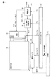
図1は、本発明の一実施形態に係る表示駆動装置を備える表示装置の一例としての液晶表示装置の構成を示す図である。図1に示す液晶表示装置は、表示パネル10と、走査ドライバ20と、信号ドライバ30と、コモン信号生成回路40と、タイミングジェネレータ50と、電源回路60と、入力部70と、を有している。
Hereinafter, embodiments of the present invention will be described with reference to the drawings.
FIG. 1 is a diagram illustrating a configuration of a liquid crystal display device as an example of a display device including a display driving device according to an embodiment of the present invention. The liquid
表示パネル10は、行方向に配設された複数の走査ラインと、列方向に配設された複数の信号ラインと、を備え、走査ラインと信号ラインとの各交点近傍には図2に示す表示画素が設けられて構成されている。
図2は、表示パネル10に設けられる1つの表示画素の等価回路を示す図である。図2に示す走査ラインGには薄膜トランジスタ(TFT)11のゲート電極が接続され、信号ラインSにはTFT11のドレイン電極が接続されている。更に、TFT11のソース電極には画素電極が接続されている。そして、画素電極と対向するように共通電極が配され、画素電極と共通電極との間に液晶が充填(挟持)されている。さらに、このようにして構成される液晶容量CLcdには蓄積容量Ccsが並列接続されている。このような構成において、画素電極と共通電極との間に電圧が印加されると、この電圧に応じて画素電極と共通電極との間に充填された液晶の配向状態が変化して液晶層中における光の透過率が変化する。これにより、図2に示す表示画素の背面に配置された図示しない光源からの光の透過状態が変化して画像表示が行われる。なお、図2にはTFT11のゲート電極−ソース電極間及び走査ライン−画素電極間に発生する寄生容量Cgsも示している。
FIG. 2 is a diagram illustrating an equivalent circuit of one display pixel provided in the
走査ドライバ20には、図2の走査ラインGが接続されている。例えば走査ドライバ20は、図3に示すように、タイミングジェネレータ50から出力される垂直制御信号Vsigや、水平制御信号Hsigとしての第1ゲートクロック信号Hsig1及び第2ゲートクロック信号Hsig2に基づいて、各走査ラインに走査信号を出力する。なお、第1ゲートクロック信号Hsig1と第2ゲートクロック信号Hsig2とは互いに逆位相の矩形信号である。
A scan line G in FIG. 2 is connected to the
走査ドライバ20の主要部における概略構成は、図4に示すように、例えば走査ライン数分(n段)の保持回路101、102、103、104、・・・が直列に配置されて構成される。そして、それぞれの保持回路は、入力端子INと、出力端子OUTと、リセット端子RSTと、クロック信号入力端子CKと、高電位電源入力端子Thと、低電位電源入力端子Tlとを有している。そして、1段目の保持回路101の入力端子INには1段目の入力信号として垂直制御信号Vsigが供給される。また、2段目以後の保持回路の入力端子INには前段の保持回路の出力信号が供給される。また、各保持回路のリセット端子RSTには次段の保持回路の出力信号が供給される。なお、最終段(例えばn段目)の保持回路(図示せず)のリセット端子RSTには、別途リセット信号ENDが供給される構成としてもよいし、1段目の保持回路101の出力信号が供給される構成としてもよい。
As shown in FIG. 4, the schematic configuration of the main part of the
さらに、奇数段目の保持回路のクロック信号入力端子CKには、第1ゲートクロック信号Hsig1が供給され、偶数段目の保持回路のクロック信号入力端子CKには、第1ゲートクロック信号Hsig1に対して逆位相となっている第2ゲートクロック信号Hsig2が供給される。また、各保持回路の高電位電源入力端子Thには所定の高電圧VGHとしてゲートオン電圧VGHが供給され、各保持回路の低電位電源入力端子Tlには所定の低電圧VGLとしてゲートオフ電圧VGLが供給される。 Further, the first gate clock signal Hsig1 is supplied to the clock signal input terminal CK of the odd-numbered holding circuit, and the clock signal input terminal CK of the even-numbered holding circuit is supplied to the first gate clock signal Hsig1. Thus, the second gate clock signal Hsig2 having an opposite phase is supplied. Further, the gate-on voltage VGH is supplied as the predetermined high voltage VGH to the high-potential power input terminal Th of each holding circuit, and the gate-off voltage VGL is supplied as the predetermined low voltage VGL to the low-potential power input terminal Tl of each holding circuit. Is done.
各保持回路101、102、103、104、・・・は、図5に示すように、それぞれ、6個のMOS型電界効果トランジスタ(以下、MOSトランジスタと記す)T11〜T16と、コンデンサCとを有している。
As shown in FIG. 5, each holding
このような走査ドライバ20は、図3に示すように、垂直制御信号Vsigに応じて当該フレームでの走査を開始するとともに、第1ゲートクロック信号Hsig1及び第2ゲートクロック信号Hsig2に応じて、所定の期間だけゲートオフ電圧VGLからゲートオン電圧VGHに切り替えるといった電圧出力を、最前段の走査ラインG(1)から順に最後段の走査ラインG(n)まで、走査ライン毎に行う。
As shown in FIG. 3, the
つまり、走査ドライバ20は、走査ライン毎に、当該走査ラインに対応するTFTを順次オン状態にし、このときに信号ラインに出力されている表示信号を対応する画素電極に書き込む。
That is, the
ここで、本実施形態における走査ドライバ20では、走査信号のゲートオフ電圧VGLとして、2種類のオフ電圧レベルVGL_1、VGL_2をコモン信号Vcomの極性反転のタイミングに合わせて交互に供給可能なように構成されている。ここで、VGL_1とVGL_2の関係は、
VGL_2=VGL_1+Vcompp
である。
Here, the
VGL_2 = VGL_1 + Vcomppp
It is.
また、走査信号の2種類のオフ電圧レベルは、詳細は後述するが、例えば電源回路60が生成し走査ドライバ20へ供給される電圧がコモン信号Vcomの極性反転のタイミングに合わせてVGL_1とVGL_2との間で振幅して出力されるように電源回路60を制御することで得ることができる。即ち、電源回路60がゲートオフ電圧としてVGL_1とVGL_2とを時分割で走査ドライバ20へ供給し、走査ドライバ20が当該供給されてきたゲートオフ電圧を各走査ラインへ出力するようにする。
The two types of off-voltage levels of the scanning signal will be described in detail later. For example, the voltage generated by the
信号ドライバ30には、図2の信号ラインSが接続され、タイミングジェネレータ50からの水平同期信号に同期して出力される水平制御信号Hsigに基づいて、入力部70から入力されるR(赤)、G(緑)、B(青)の各色の表示データを1行単位で取り込み、この取り込んだ表示データに対応する表示信号Vsを生成して信号ラインSに供給する。また、フレームの開始とともにタイミングジェネレータ50から入力される極性反転制御信号Polに応じて表示信号Vsの電圧レベルをある中心電圧を中心として反転させる。即ち、信号ドライバ30は、1画面分の表示データに対応した表示信号を表示パネル10に供給する毎に表示信号Vsの電圧レベルが液晶に印加される電圧の極性を反転させる電圧レベルとなるようにある中心電圧を中心として反転させる。
2 is connected to the
コモン信号生成回路40は、フレームの開始とともにタイミングジェネレータ50から入力される極性反転制御信号Polに対応させて、電源回路60によって供給される2種類の共通電圧VcomH、VcomLの一方を交互に選択することでコモン信号Vcomを生成して共通電極に供給する。
The common
タイミングジェネレータ50は、入力部70から入力される垂直同期信号に基づいて上述したような垂直制御信号Vsigや、極性反転制御信号Polを生成するとともに、入力部70から入力される水平同期信号に基づいて水平制御信号Hsigを生成し、生成した各制御信号をそれぞれ供給する。
The
電源回路60は、走査ドライバ20、信号ドライバ30、コモン信号生成回路40における各種駆動電圧を生成して供給するもので、詳細は後述するが電源電圧Vccを昇圧する昇圧回路等を備えて構成されている。
The
次に、図1のような構成を有する表示装置の動作について説明する。
入力部70を介して垂直同期信号が供給されるとタイミングジェネレータ50において極性反転制御信号Pol及び垂直制御信号Vsigが生成される。そして、垂直制御信号Vsigは走査ドライバ20及び信号ドライバ30に、極性反転制御信号Polは信号ドライバ30、コモン信号生成回路40、及び電源回路60に出力される。また、入力部70を介して水平同期信号が供給されるとタイミングジェネレータ50において水平制御信号Hsigが生成されて走査ドライバ20及び信号ドライバ30に出力される。
Next, the operation of the display device having the configuration as shown in FIG. 1 will be described.
When the vertical synchronization signal is supplied via the
垂直制御信号Vsigが入力されると、走査ドライバ20は当該フレームにおける走査ラインの走査を開始するとともに、信号ドライバ30は、当該フレームにおける表示データに対応した表示信号の信号ラインへの供給を開始する。
When the vertical control signal Vsig is input, the
そして、走査ドライバ20は、水平制御信号Hsigに同期させて、1行分のTFT11をオン状態とするための走査信号としてゲートオン電圧VGHを各走査ラインGに順次走査ライン毎に印加する。このとき、オフ状態とすべきTFT11に対応する走査ラインには走査信号としてゲートオフ電圧VGLを印加する。そして、ゲートオフ電圧VGLのオフ電圧レベルは、電源回路60から時分割的に供給されてくるVGL_1及びVGL_2の何れか一方の値がそのタイミングによって自動的に適用される。また、信号ドライバ30は、走査ドライバ20が走査信号によってTFT11をオン状態にする表示画素に対応した走査信号を供給する。
The
一方、コモン信号生成回路40は、互いに異なる電圧レベルの共通電圧VcomLとVcomHとを、極性反転制御信号Polを受ける毎に交互に共通電極に印加する。ここで、コモン信号生成回路40は、正極期間(Vs>Vcomとする期間)ではVcomLを供給し、負極期間(Vs<Vcomとする期間)ではVcomHを供給する。即ち、コモン信号生成回路40は、コモン信号Vcomの振幅中心電圧に対して正極側の電圧レベルであるVcomHを、液晶に印加される電圧が負極性になる表示信号を信号ドライバ30が信号ラインに供給する期間である負極期間に出力する。また、負極側の電圧レベルであるVcomLを、液晶に印加される電圧が正極性になる表示信号を信号ドライバ30が信号ラインに供給する期間である正極期間に出力する。
On the other hand, the common
そして表示パネル10において、走査信号におけるゲートオン電圧が供給されてオン状態となっているTFT11に表示信号Vsが印加されると、表示画素ではTFT11を介して画素電極に表示信号Vsが画素電極電位Vs’として保持される。これにより、画素電極電位Vs’とコモン信号Vcom(VcomL又はVcomH)との差に応じた電圧が液晶に印加される。これによって液晶の配向状態が変化して液晶層中における光の透過率が変化して表示が行われる。
In the
上述したように走査ドライバ20は、表示画素への表示信号Vsの書き込みが終了するタイミングで1行分のTFT11をオフ状態とするための走査信号としてオフ電圧VGL_1又はVGL_2を走査ラインGに印加する。ここで、本実施形態では、コモン信号の電圧レベルがVcomHからVcomLに切り替わるタイミングで走査信号におけるゲートオフ電圧の電圧レベルをVGL_2からVGL_1に切り替え、コモン信号の電圧レベルがVcomLからVcomHに切り替わるタイミングでオフ電圧レベルをVGL_1からVGL_2に切り替えるようにしている。
As described above, the
なお、走査ラインを介してTFT11のゲート電極に印加されるゲートオフ電圧の電圧レベルがVGL_1とVGL_2との間で切り替わってもTFT11はオフ状態を維持することが可能な値であり、液晶に印加された電圧は次の表示信号Vsの印加時(即ち、次のフレームにおいてTFT11が再びオン状態となるまで)補助容量Ccsによって保持される。
Note that even if the voltage level of the gate-off voltage applied to the gate electrode of the
図6は、本実施形態におけるフレーム反転駆動時における画素電極電位Vs’の時系列変化を示している。また、図7は、本実施形態におけるフレーム反転駆動時のモデル図を示している。図6に示すように、本実施形態においては、コモン信号Vcomが電圧レベルVcomHからVcomLに切り替わるのに応じて走査信号のオフ電圧レベルをVGL_2からVGL_1に切り替え、コモン信号Vcomの電圧レベルがVcomLからVcomHに切り替わるのに応じて走査信号のオフ電圧レベルをVGL_1からVGL_2に切り替えている。これにより、極性反転時の画素電位VLCDの変化量ΔV2を、
ΔV2=Vcompp
とすることができる。
FIG. 6 shows a time-series change of the pixel electrode potential Vs ′ during the frame inversion driving in the present embodiment. FIG. 7 shows a model diagram during frame inversion driving in the present embodiment. As shown in FIG. 6, in the present embodiment, in response to the common signal Vcom switching from the voltage level VcomH to VcomL, the off-voltage level of the scanning signal is switched from VGL_2 to VGL_1, and the voltage level of the common signal Vcom is changed from VcomL. The off voltage level of the scanning signal is switched from VGL_1 to VGL_2 in accordance with the switching to VcomH. Thereby, the change amount ΔV2 of the pixel potential VLCD at the time of polarity inversion is
ΔV2 = Vcomppp
It can be.
即ち、本実施形態では、コモン信号Vcomにおける電圧レベルの変化量と同じ電圧レベル変化を、走査信号のゲートオフ電圧VGLにも与えるようにしている。これにより、極性反転時の画素電極電位Vs’の変化量ΔV2をコモン信号Vcomにおける電圧レベルの変化量Vcomppと同じくすることができる。したがって、画素電極電位Vs’とコモン信号Vcomとの差である液晶への印加電圧VLCD(液晶への印加電圧)が極性反転前後で変化することがない。これにより、1画面で同一輝度の表示を行ったような場合でも、画面上部から画面下部にかけての輝度傾斜を発生させることがない。
That is, in this embodiment, the same voltage level change as the voltage level change amount in the common signal Vcom is also applied to the gate-off voltage VGL of the scanning signal. Thereby, the change amount ΔV2 of the pixel electrode potential Vs ′ at the time of polarity inversion can be made the same as the change amount Vcompp of the voltage level in the common signal Vcom. Therefore, the applied voltage VLCD (applied voltage to the liquid crystal) applied to the liquid crystal, which is the difference between the pixel electrode potential Vs ′ and the common signal Vcom , does not change before and after the polarity inversion. As a result, even when the same luminance is displayed on one screen, a luminance gradient is not generated from the upper part of the screen to the lower part of the screen.
以下、図8、図9、図10(a)、及び図10(b)に基づいて、電源回路60におけるコモン信号の電圧レベルVcomL、VcomH及び走査信号のオフ電圧レベルVGL_1、VGL_2の生成について詳述する。
Hereinafter, the generation of the voltage levels VcomL and VcomH of the common signal and the OFF voltage levels VGL_1 and VGL_2 of the scanning signal in the
電源回路60は、電源電圧Vccに基づいて、コモン信号に適用される負極側の電圧レベルVcomLを生成する第1電圧変換部60Aと、コモン信号に適用される正極側の電圧レベルVcomH及び走査信号に適用されるオフ電圧レベルVGL_1、VGL_2を生成する第2電圧変換部60B等を備えている。
The
第1電圧変換部60Aは、例えば電源電圧Vccを大凡−1倍に昇圧するチャージポンプ方式の昇圧回路61(以下、便宜上、第1反転回路61と記す)からなり、この第1反転回路61は例えば4つのスイッチSa1、Sa2、Sa3、Sa4と、昇圧用コンデンサCa1と、平滑コンデンサCa2とから構成されている。この第1反転回路61は、スイッチSa1、Sa3がオン(ショート)であるとともにスイッチSa2、Sa4がオフ(オープン)である第1接続状態と、スイッチSa1、Sa3がオフであるとともにスイッチSa2、Sa4がオンである第2接続状態とを有している。これら第1接続状態と第2接続状態とを所定の周期で切り替えることにより、VcomL用出力端子Taでの電圧が目的の電圧レベルVcomLで維持されるように制御がなされる。なお、第1反転回路61は、VcomL用出力端子Taに出力される電圧をDC調整するレギュレータをさらに備え、当該レギュレータによりDC調整された電圧が負極側の電圧レベルVcomLとなるようにさらに制御して出力する構成としてもよい。
The first
また、第2電圧変換部60Bは、それぞれが所定の電圧を昇圧または極性反転して出力する4つのチャージポンプ方式の昇圧回路、即ち第1昇圧回路62、第2昇圧回路63、第3昇圧回路64、第2反転回路65を備え、これらは直列接続されている。さらに、第2電圧変換部60Bは、所定の昇圧回路を所定のタイミングでバイパスさせるバイパス回路66を備えている。
The second
第1昇圧回路62は、例えば電源電圧Vccを大凡2倍に昇圧して電圧レベルVcomHを生成するもので、オフ電圧レベルVGL_1、VGL_2の生成過程の一過程として電圧レベルVcomHを生成する。そして、第1昇圧回路62は、4つのスイッチSb1、Sb2、Sb3、Sb4と、昇圧用コンデンサCb1と、平滑コンデンサCb2と、から構成されている。この第1昇圧回路62は、スイッチSb1、Sb3がオンであるとともにスイッチSb2、Sb4がオフである第3接続状態と、スイッチSa1、Sa3がオフであるとともにスイッチSa2、Sa4がオンである第4接続状態と、を有している。これら第3接続状態と第4接続状態とを所定の周期で切り替えることにより、VcomH用出力端子Tbでの電圧が予め設定されている電圧レベルVcomHで維持されるように制御がなされる。なお、第1昇圧回路62は、VcomH用出力端子Tbに出力される電圧をDC調整するレギュレータをさらに備え、当該レギュレータによりDC調整された電圧が負極側の電圧レベルVcomHとなるようにさらに制御して出力する構成としてもよい。
The
第2昇圧回路63は、第1昇圧回路62が昇圧して出力する電圧レベルVcomHとしての第1昇圧電圧2Vccを更に大凡2倍に昇圧し、これを第2昇圧電圧として出力するもので、4つのスイッチSc1、Sc2、Sc3、Sc4と、昇圧用コンデンサCc1と、平滑コンデンサCc2と、から構成されている。この第2昇圧回路63は、スイッチSc1、Sc3がオンであるとともにスイッチSc2、Sc4がオフである第5接続状態と、スイッチSc1、Sc3がオフであるとともにスイッチSc2、Sc4がオンである第6接続状態と、を有している。これら第5接続状態と第6接続状態とを所定の周期で切り替えることにより、出力電圧が予め設定されている電圧レベル、例えば4Vccで維持されるように制御がなされる。
The
第3昇圧回路64は、第2昇圧回路63が昇圧して出力する第2昇圧電圧4Vccを更に大凡2倍に昇圧し、これを第3昇圧電圧として出力するもので、4つのスイッチSd1、Sd2、Sd3、Sd4と、昇圧用コンデンサCd1と、平滑コンデンサCd2と、から構成されている。この第3昇圧回路64は、スイッチSd1、Sd3がオンであるとともにスイッチSd2、Sd4がオフである第7接続状態と、スイッチSd1、Sd3がオフであるとともにスイッチSd2、Sd4がオンである第8接続状態と、を有している。これら第7接続状態と第8接続状態とを所定の周期で切り替えることにより、出力電圧が予め設定されている電圧レベル、例えば8Vccで維持されるように制御がなされる。
The
ここで、第2電圧変換部60Bでは、第3昇圧回路64に対してバイパス回路66が並列接続され、このバイパス回路66によって、第2昇圧回路63からの第2昇圧電圧4Vccと第3昇圧回路64からの第3昇圧電圧8Vccとの何れか一方が、後段の第2反転回路65に出力されるように構成されている。即ち、バイパス回路66は、第2昇圧回路64からの第2昇圧電圧4Vccと第3昇圧回路64からの第3昇圧電圧8Vccの何れか一方を極性反転信号Polに基づいて第2反転回路65へ送出する選択スイッチSw1を備えている。そして、この選択スイッチSw1の極性反転信号Polに基づく動作により、コモン信号Vcomとして電圧レベルVcomLが共通電極に印加されるタイミングのときに、図8や図10(a)に示すように、第3昇圧回路64からの第3昇圧電圧8Vccが第2反転回路65に入力される。また、コモン信号Vcomとして電圧レベルVcomHが共通電極に印加されるタイミングのときに、図9や図10(b)に示すように、第2昇圧回路63からの第2昇圧電圧4Vccが第2反転回路65に入力される。
Here, in the
つまり、第2電圧変換部60Bは、共通電極に印加されるコモン信号Vcomにおける電圧レベルの変化に同期して電源電圧Vccの昇圧比を可変にできるように構成されている。
That is, the
第2反転回路65は、第3昇圧回路64が昇圧して出力する第2昇圧電圧4Vccまたは第3昇圧電圧8Vccを大凡−1倍に昇圧する昇圧回路であり、4つのスイッチSe1、Se2、Se3、Se4と、反転用コンデンサCe1と、平滑コンデンサCe2と、から構成されている。この第2反転回路65は、スイッチSe1、Se3がオンであるとともにスイッチSe2、Se4がオフである第9接続状態と、スイッチSe1、Se3がオフであるとともにスイッチSe2、Se4がオンである第10接続状態と、を有している。これら第9接続状態と第10接続状態とを所定の周期で切り替えることにより、バイパス回路66から第3昇圧電圧8Vccが入力されてくるときにはオフ電圧レベルVGL_1として−8Vccが出力され、バイパス回路66から第2昇圧電圧4Vccが入力されてくるときにはオフ電圧レベルVGL_2として−4Vccが出力される。なお、第9接続状態と第10接続状態との切り替え周期は、コモン信号Vcomにおける電圧レベルの切り替わり周期よりも十分に短いことが好ましい。
The
このように、本実施の形態の電源回路60では、比較的昇圧比が大きいものの互いの電圧差が比較的小さく且つ互いに異なるタイミングで必要とされる(時分割的に必要とされる)複数の昇圧電圧を生成する際に、昇圧比が比較的小さい昇圧回路を複数備え、必要となるタイミングのときに必要な昇圧回路を直列に接続するように構成している。換言すると、比較的昇圧比が大きいものの互いの電圧差が比較的小さい昇圧電圧を複数生成する際に、互いに共通の昇圧回路を用いて生成可能なように構成するとともに、複数の昇圧電圧が時分割的に生成されるように構成している。従って、本実施の形態の電源回路60では、回路規模を比較的小さくすることが可能になるとともに消費電力を抑制することが可能になる。例えば、電圧変換部をそれぞれの昇圧電圧に対応させて個別に且つ常時出力可能に構成することもできるが、このような場合には、それぞれに対応した個別の電圧変換部を必要とし回路規模が比較的大きくなり、また、消費電力も増大するという問題が発生するが、本実施の形態では、上述の構成とすることにより、回路規模を比較的小さくすることを、また、消費電力を抑制することを可能にしている。
As described above, in the
なお、上述した第2電圧変換部60Bでは、第3昇圧回路64に対してバイパス回路66を並列接続し、バイパス回路66が第2昇圧回路63からの出力と第3昇圧回路64からの出力とを選択して後段の第2反転回路65に選択した出力電圧を入力させる場合について説明したが、第2昇圧回路63に対してバイパス回路を並列接続し、バイパス回路が第1昇圧回路62からの出力と第2昇圧回路63からの出力とを選択して、この場合に後段の昇圧回路となる第3昇圧回路64に選択した出力電圧を入力させる構成としてもよい。また、各昇圧回路の昇圧倍率は2倍に限定するものでなく、出力電圧が目的の電圧となるように適宜各昇圧回路の昇圧倍率を設定すればよい。
Note that the output from the second the
以上実施形態に基づいて本発明を説明したが、本発明は上記した実施形態に限定されるものではなく、本発明の要旨の範囲内で種々の変形や応用が可能なことは勿論である。例えば、図6に示す例では、走査信号のゲートオフ電圧VGLの電圧レベルの切り替えタイミングとコモン信号Vcomの極性反転タイミングとを一致させている。しかし、フレームの切れ目に設けられる垂直帰線期間内に、走査信号のゲートオフ電圧VGLの電圧レベルの切り替えとコモン信号Vcomの極性反転とを行うのであれば、走査信号におけるゲートオフ電圧VGLのオフ電圧レベルの切り替えタイミングとコモン信号Vcomの極性反転タイミングとがたとえずれたとしても、表示状態に影響を与えることなく画面内における輝度傾斜の発生を防止することができる。換言すると、フレームの切れ目に設けられる垂直帰線期間内に、走査信号におけるゲートオフ電圧のオフ電圧レベルの切り替えとコモン信号Vcomの極性反転とを行えば、必要以上に、オフ電圧レベルの切り替えタイミングと極性反転タイミングとを一致させなくても、表示状態に不都合を生じさせることがなく好ましい。 Although the present invention has been described based on the above embodiments, the present invention is not limited to the above-described embodiments, and various modifications and applications are naturally possible within the scope of the gist of the present invention. For example, in the example shown in FIG. 6, the switching timing of the voltage level of the gate-off voltage VGL of the scanning signal is matched with the polarity inversion timing of the common signal Vcom. However, if the switching of the voltage level of the gate-off voltage VGL of the scanning signal and the polarity inversion of the common signal Vcom are performed within the vertical blanking period provided at the frame break, the off-voltage level of the gate-off voltage VGL in the scanning signal Even if the switching timing and the polarity inversion timing of the common signal Vcom deviate from each other, it is possible to prevent the occurrence of a luminance gradient in the screen without affecting the display state. In other words, if the switching of the off-voltage level of the gate-off voltage in the scanning signal and the polarity inversion of the common signal Vcom are performed within the vertical blanking period provided at the frame break, the switching timing of the off-voltage level is more than necessary. Even if the polarity reversal timing is not coincident, it is preferable because no inconvenience is caused in the display state.
さらに、上記した実施形態には種々の段階の発明が含まれており、開示される複数の構成要件の適当な組合せにより種々の発明が抽出され得る。例えば、実施形態に示される全構成要件からいくつかの構成要件が削除されても、上述したような課題を解決でき、上述したような効果が得られる場合には、この構成要件が削除された構成も発明として抽出され得る。 Further, the above-described embodiments include various stages of the invention, and various inventions can be extracted by appropriately combining a plurality of disclosed constituent elements. For example, even if some configuration requirements are deleted from all the configuration requirements shown in the embodiment, the above-described problem can be solved, and this configuration requirement is deleted when the above-described effects can be obtained. The configuration can also be extracted as an invention.
10…表示パネル、20…走査ドライバ、30…信号ドライバ、40…共通電圧発生回路、50…タイミングジェネレータ、60…電源回路、70…入力部
DESCRIPTION OF
Claims (9)
前記走査ラインに走査信号を出力する走査手段と、
前記コモン信号の電圧極性が反転される毎に、前記走査信号のオフ電圧レベルを、第1の電圧レベルVGL1と、前記第1の電圧レベルVGL1とは異なる第2の電圧レベルVGL2と、の間で切り替える切り替え手段と、
を有する走査側駆動手段を具備し、
前記コモン信号の前記所定の中心電圧に対して正極側のコモン電圧レベルVcomHと負極側のコモン電圧レベルVcomLとの差をVcomppとすると、
前記切り替え手段は、前記コモン信号が前記所定の中心電圧に対して前記負極側のコモン電圧レベルVcomLとなった場合に前記オフ電圧レベルを前記第1の電圧レベルVGL1に切り替え、前記コモン信号が前記所定の中心電圧に対して前記正極側のコモン電圧レベルVcomHとなった場合に前記オフ電圧レベルを前記第1の電圧レベルVGL1よりも前記走査信号電圧のオンレベル側になる前記第2の電圧レベルVGL2に切り替え、
前記第1の電圧レベルVGL1と前記第2の電圧レベルVGL2との関係は、
VGL2=VGL1+Vcompp
であり、且つ、
VcomH>0>VcomL>VGL2>VGL1
である、
ことを特徴とする表示駆動装置。 A pixel electrode that is arranged so as to correspond to the intersection of the scanning line and the signal line and to which a display signal based on display data is applied, and is arranged to face each of the pixel electrodes, and based on a vertical synchronization signal In a display driving device for driving a display panel having a common electrode to which a common signal whose polarity is inverted with respect to a predetermined center voltage at a timing is applied,
Scanning means for outputting a scanning signal to the scanning line;
Each time the voltage polarity of the common signal is inverted, the scanning signal is turned off between a first voltage level VGL1 and a second voltage level VGL2 different from the first voltage level VGL1. Switching means to switch with,
Scanning side driving means having
When the difference between the common voltage level VcomH on the positive side and the common voltage level VcomL on the negative side with respect to the predetermined center voltage of the common signal is Vcompp,
The switching means switches the off voltage level to the first voltage level VGL1 when the common signal becomes the negative common voltage level VcomL with respect to the predetermined center voltage, and the common signal is When the common voltage level VcomH on the positive electrode side with respect to a predetermined center voltage is reached, the off voltage level becomes the second voltage level that is on the on level side of the scanning signal voltage with respect to the first voltage level VGL1. Switch to VGL2,
The relationship between the first voltage level VGL1 and the second voltage level VGL2 is:
VGL2 = VGL1 + Vcomppp
And
VcomH>0>VcomL>VGL2> VGL1
Is,
A display driving device characterized by that.
前記走査ラインに走査信号を出力する走査側駆動手段を具備し、
前記走査側駆動手段は、前記コモン信号の電圧極性が反転される毎に、前記走査信号のオフ電圧レベルを、第1の電圧レベルVGL1と、前記第1の電圧レベルVGL1とは異なる第2の電圧レベルVGL2と、の間で切り替える切り替え手段を有し、
前記コモン信号の前記所定の中心電圧に対して正極側のコモン電圧レベルVcomHと負極側のコモン電圧レベルVcomLとの差をVcomppとすると、
前記切り替え手段は、前記コモン信号が前記所定の中心電圧に対して前記負極側のコモン電圧レベルVcomLとなった場合に前記オフ電圧レベルを前記第1の電圧レベルVGL1に切り替え、前記コモン信号が前記所定の中心電圧に対して前記正極側のコモン電圧レベルVcomHとなった場合に前記オフ電圧レベルを前記第1の電圧レベルVGL1よりも前記走査信号電圧のオンレベル側になる前記第2の電圧レベルVGL2に切り替え、
前記第1の電圧レベルVGL1と前記第2の電圧レベルVGL2との関係は、
VGL2=VGL1+Vcompp
であり、且つ、
VcomH>0>VcomL>VGL2>VGL1
である、
ことを特徴とする表示装置。 A pixel electrode that is arranged so as to correspond to the intersection of the scanning line and the signal line and to which a display signal based on display data is applied, and is arranged to face each of the pixel electrodes, and based on a vertical synchronization signal In a display device having a common electrode to which a common signal whose polarity is inverted with respect to a predetermined center voltage at a timing is applied,
Scanning side driving means for outputting a scanning signal to the scanning line;
The scanning-side drive means sets the off-voltage level of the scanning signal to a first voltage level VGL1 and a second voltage level different from the first voltage level VGL1 each time the voltage polarity of the common signal is inverted. Switching means for switching between the voltage level VGL2 and
When the difference between the common voltage level VcomH on the positive side and the common voltage level VcomL on the negative side with respect to the predetermined center voltage of the common signal is Vcompp,
The switching means switches the off voltage level to the first voltage level VGL1 when the common signal becomes the negative common voltage level VcomL with respect to the predetermined center voltage, and the common signal is When the common voltage level VcomH on the positive electrode side with respect to a predetermined center voltage is reached, the off voltage level becomes the second voltage level that is on the on level side of the scanning signal voltage with respect to the first voltage level VGL1. Switch to VGL2,
The relationship between the first voltage level VGL1 and the second voltage level VGL2 is:
VGL2 = VGL1 + Vcomppp
And
VcomH>0>VcomL>VGL2> VGL1
Is,
A display device characterized by that.
1画面分の表示データに対応した表示信号を前記表示パネルに供給する毎に、所定の中心電圧に対して正極側のコモン電圧レベルVcomHと負極側のコモン電圧レベルVcomLとの間で前記コモン信号の電圧レベルが切り替わる表示装置において、
前記コモン信号における電圧レベルの切り替わりに同期させて、前記画素トランジスタのオフ電圧レベルを、第1の電圧レベルVGL1と前記第1の電圧レベルVGL1とは異なる第2の電圧レベルVGL2との間で切り替える切り替え手段を有し、
前記コモン信号の前記所定の中心電圧に対して前記正極側のコモン電圧レベルVcomHと前記負極側のコモン電圧レベルVcomLとの差をVcomppとすると、
前記切り替え手段は、前記コモン信号が前記所定の中心電圧に対して前記負極側のコモン電圧レベルVcomLとなった場合に前記オフ電圧レベルを前記第1の電圧レベルVGL1に切り替え、前記コモン信号が前記所定の中心電圧に対して前記正極側のコモン電圧レベルVcomHとなった場合に前記オフ電圧レベルを前記第1の電圧レベルVGL1よりも前記走査信号電圧のオンレベル側になる前記第2の電圧レベルVGL2に切り替え、
前記第1の電圧レベルVGL1と前記第2の電圧レベルVGL2との関係は、
VGL2=VGL1+Vcompp
であり、且つ、
VcomH>0>VcomL>VGL2>VGL1
である、
ことを特徴とする表示装置。 A display panel in which liquid crystal is sandwiched between a pixel electrode to which a display signal is applied via a pixel transistor and a common electrode to which a common signal common to each display pixel is applied;
Each time a display signal corresponding to display data for one screen is supplied to the display panel, the common signal is between a positive common voltage level VcomH and a negative common voltage level VcomL with respect to a predetermined center voltage. In the display device in which the voltage level is switched,
In synchronization with the switching of the voltage level in the common signal, the off-voltage level of the pixel transistor is switched between the first voltage level VGL1 and the second voltage level VGL2 different from the first voltage level VGL1. Having a switching means,
When the difference between the positive common voltage level VcomH and the negative common voltage level VcomL with respect to the predetermined center voltage of the common signal is Vcompp,
The switching means switches the off voltage level to the first voltage level VGL1 when the common signal becomes the negative common voltage level VcomL with respect to the predetermined center voltage, and the common signal is When the common voltage level VcomH on the positive electrode side with respect to a predetermined center voltage is reached, the off voltage level becomes the second voltage level that is on the on level side of the scanning signal voltage with respect to the first voltage level VGL1. Switch to VGL2,
The relationship between the first voltage level VGL1 and the second voltage level VGL2 is:
VGL2 = VGL1 + Vcomppp
And
VcomH>0>VcomL>VGL2> VGL1
Is,
A display device characterized by that.
Priority Applications (1)
| Application Number | Priority Date | Filing Date | Title |
|---|---|---|---|
| JP2008217970A JP5359121B2 (en) | 2007-08-29 | 2008-08-27 | Display driving device and display device |
Applications Claiming Priority (3)
| Application Number | Priority Date | Filing Date | Title |
|---|---|---|---|
| JP2007222594 | 2007-08-29 | ||
| JP2007222594 | 2007-08-29 | ||
| JP2008217970A JP5359121B2 (en) | 2007-08-29 | 2008-08-27 | Display driving device and display device |
Publications (3)
| Publication Number | Publication Date |
|---|---|
| JP2009075580A JP2009075580A (en) | 2009-04-09 |
| JP2009075580A5 JP2009075580A5 (en) | 2011-03-10 |
| JP5359121B2 true JP5359121B2 (en) | 2013-12-04 |
Family
ID=40610543
Family Applications (3)
| Application Number | Title | Priority Date | Filing Date |
|---|---|---|---|
| JP2008217968A Active JP5353123B2 (en) | 2007-08-29 | 2008-08-27 | Display device |
| JP2008217970A Active JP5359121B2 (en) | 2007-08-29 | 2008-08-27 | Display driving device and display device |
| JP2008217969A Active JP5353124B2 (en) | 2007-08-29 | 2008-08-27 | Display device |
Family Applications Before (1)
| Application Number | Title | Priority Date | Filing Date |
|---|---|---|---|
| JP2008217968A Active JP5353123B2 (en) | 2007-08-29 | 2008-08-27 | Display device |
Family Applications After (1)
| Application Number | Title | Priority Date | Filing Date |
|---|---|---|---|
| JP2008217969A Active JP5353124B2 (en) | 2007-08-29 | 2008-08-27 | Display device |
Country Status (1)
| Country | Link |
|---|---|
| JP (3) | JP5353123B2 (en) |
Cited By (1)
| Publication number | Priority date | Publication date | Assignee | Title |
|---|---|---|---|---|
| US8744099B2 (en) | 2010-05-28 | 2014-06-03 | Kabushiki Kaisha Audio-Technica | Battery compartment for condenser microphone |
Families Citing this family (7)
| Publication number | Priority date | Publication date | Assignee | Title |
|---|---|---|---|---|
| CN102959615B (en) * | 2010-06-30 | 2016-02-03 | 夏普株式会社 | Signal generating circuit and liquid crystal indicator |
| JP6046413B2 (en) | 2011-08-08 | 2016-12-14 | 三星ディスプレイ株式會社Samsung Display Co.,Ltd. | Display device and driving method thereof |
| US9019188B2 (en) | 2011-08-08 | 2015-04-28 | Samsung Display Co., Ltd. | Display device for varying different scan ratios for displaying moving and still images and a driving method thereof |
| US9299301B2 (en) | 2011-11-04 | 2016-03-29 | Samsung Display Co., Ltd. | Display device and method for driving the display device |
| US9208736B2 (en) | 2011-11-28 | 2015-12-08 | Samsung Display Co., Ltd. | Display device and driving method thereof |
| US9129572B2 (en) | 2012-02-21 | 2015-09-08 | Samsung Display Co., Ltd. | Display device and related method |
| KR102348666B1 (en) * | 2015-06-30 | 2022-01-07 | 엘지디스플레이 주식회사 | Display device and mobile terminal using the same |
Family Cites Families (10)
| Publication number | Priority date | Publication date | Assignee | Title |
|---|---|---|---|---|
| JPH07128639A (en) * | 1993-11-04 | 1995-05-19 | Sharp Corp | Display device |
| JPH07139127A (en) * | 1993-11-19 | 1995-05-30 | Inax Corp | Tile panel |
| JP3265802B2 (en) * | 1994-03-17 | 2002-03-18 | 株式会社日立製作所 | Liquid crystal display |
| JPH10301087A (en) * | 1997-04-24 | 1998-11-13 | Hitachi Ltd | Liquid crystal display device |
| JP3948224B2 (en) * | 2001-06-07 | 2007-07-25 | 株式会社日立製作所 | Display device |
| JP3854905B2 (en) * | 2002-07-30 | 2006-12-06 | 株式会社 日立ディスプレイズ | Liquid crystal display |
| JP4543964B2 (en) * | 2004-03-04 | 2010-09-15 | セイコーエプソン株式会社 | Common voltage generation circuit, power supply circuit, display driver, and display device |
| JP4858250B2 (en) * | 2004-03-04 | 2012-01-18 | セイコーエプソン株式会社 | Common voltage generation circuit, power supply circuit, display driver, and common voltage generation method |
| JP2006185530A (en) * | 2004-12-28 | 2006-07-13 | Renesas Technology Corp | Nonvolatile semiconductor memory device |
| JP4356617B2 (en) * | 2005-01-20 | 2009-11-04 | セイコーエプソン株式会社 | Power supply circuit, display driver, electro-optical device, electronic apparatus, and control method for power supply circuit |
-
2008
- 2008-08-27 JP JP2008217968A patent/JP5353123B2/en active Active
- 2008-08-27 JP JP2008217970A patent/JP5359121B2/en active Active
- 2008-08-27 JP JP2008217969A patent/JP5353124B2/en active Active
Cited By (1)
| Publication number | Priority date | Publication date | Assignee | Title |
|---|---|---|---|---|
| US8744099B2 (en) | 2010-05-28 | 2014-06-03 | Kabushiki Kaisha Audio-Technica | Battery compartment for condenser microphone |
Also Published As
| Publication number | Publication date |
|---|---|
| JP2009075580A (en) | 2009-04-09 |
| JP5353123B2 (en) | 2013-11-27 |
| JP2009075579A (en) | 2009-04-09 |
| JP2009075578A (en) | 2009-04-09 |
| JP5353124B2 (en) | 2013-11-27 |
Similar Documents
| Publication | Publication Date | Title |
|---|---|---|
| JP5359121B2 (en) | Display driving device and display device | |
| KR100878244B1 (en) | circuit for generating driving voltages and liquid crystal device using the same | |
| US8059219B2 (en) | Liquid crystal display and driving method of the same | |
| JP6234662B2 (en) | Display device | |
| KR100659621B1 (en) | Active matrix type liquid crystal display device | |
| US8432343B2 (en) | Liquid crystal display device and driving method thereof | |
| US20070097057A1 (en) | Liquid crystal display and driving method thereof | |
| US20080278467A1 (en) | Liquid crystal display having progressive and interlaced modes, and driving method of the liquid crystal display | |
| US8279210B2 (en) | Display apparatus and method of driving the same | |
| JP4680874B2 (en) | Liquid crystal display device and driving method thereof | |
| JP4982349B2 (en) | Liquid crystal display device and driving method thereof | |
| CN107564448B (en) | Display control and touch control device, and display and touch detection panel unit | |
| CN102792358A (en) | Display device, method for driving same, and liquid crystal display device | |
| US20060083033A1 (en) | Voltage generator, method of generating voltage, display device having the voltage generator and apparatus for driving the display device | |
| KR101441385B1 (en) | Driving apparatus for liquid crystal display device and method for driving the same | |
| TWI395193B (en) | Lcd driver circuit and driving method thereof | |
| JP5244352B2 (en) | Display device and storage drive circuit thereof | |
| KR101284940B1 (en) | Apparatus and method for driving a liquid crystal display | |
| KR20080026278A (en) | Data driver device and driving mhthod therof | |
| KR20080086060A (en) | Liquid crystal display and driving method of the same | |
| JP2006276457A (en) | Voltage generating circuit in liquid crystal drive circuit | |
| JP4692871B2 (en) | Display driving device and display device | |
| KR20080022801A (en) | Liquid crystal diplay | |
| KR100811321B1 (en) | liquid crystal dispaly | |
| JP2007093722A (en) | Driving device |
Legal Events
| Date | Code | Title | Description |
|---|---|---|---|
| A521 | Request for written amendment filed |
Free format text: JAPANESE INTERMEDIATE CODE: A523 Effective date: 20110124 |
|
| A621 | Written request for application examination |
Free format text: JAPANESE INTERMEDIATE CODE: A621 Effective date: 20110124 |
|
| A977 | Report on retrieval |
Free format text: JAPANESE INTERMEDIATE CODE: A971007 Effective date: 20120808 |
|
| A131 | Notification of reasons for refusal |
Free format text: JAPANESE INTERMEDIATE CODE: A131 Effective date: 20120828 |
|
| A521 | Request for written amendment filed |
Free format text: JAPANESE INTERMEDIATE CODE: A523 Effective date: 20121026 |
|
| A131 | Notification of reasons for refusal |
Free format text: JAPANESE INTERMEDIATE CODE: A131 Effective date: 20130507 |
|
| A521 | Request for written amendment filed |
Free format text: JAPANESE INTERMEDIATE CODE: A523 Effective date: 20130708 |
|
| TRDD | Decision of grant or rejection written | ||
| A01 | Written decision to grant a patent or to grant a registration (utility model) |
Free format text: JAPANESE INTERMEDIATE CODE: A01 Effective date: 20130806 |
|
| A61 | First payment of annual fees (during grant procedure) |
Free format text: JAPANESE INTERMEDIATE CODE: A61 Effective date: 20130819 |
|
| R150 | Certificate of patent or registration of utility model |
Ref document number: 5359121 Country of ref document: JP Free format text: JAPANESE INTERMEDIATE CODE: R150 Free format text: JAPANESE INTERMEDIATE CODE: R150 |
|
| S111 | Request for change of ownership or part of ownership |
Free format text: JAPANESE INTERMEDIATE CODE: R313113 |
|
| R350 | Written notification of registration of transfer |
Free format text: JAPANESE INTERMEDIATE CODE: R350 |
|
| R250 | Receipt of annual fees |
Free format text: JAPANESE INTERMEDIATE CODE: R250 |
|
| R250 | Receipt of annual fees |
Free format text: JAPANESE INTERMEDIATE CODE: R250 |
|
| R250 | Receipt of annual fees |
Free format text: JAPANESE INTERMEDIATE CODE: R250 |
|
| R250 | Receipt of annual fees |
Free format text: JAPANESE INTERMEDIATE CODE: R250 |
|
| R250 | Receipt of annual fees |
Free format text: JAPANESE INTERMEDIATE CODE: R250 |
|
| R250 | Receipt of annual fees |
Free format text: JAPANESE INTERMEDIATE CODE: R250 |
|
| R250 | Receipt of annual fees |
Free format text: JAPANESE INTERMEDIATE CODE: R250 |
|
| R250 | Receipt of annual fees |
Free format text: JAPANESE INTERMEDIATE CODE: R250 |