JP5357302B2 - Dispensing equipment chemical stock structure - Google Patents
Dispensing equipment chemical stock structure Download PDFInfo
- Publication number
- JP5357302B2 JP5357302B2 JP2012119234A JP2012119234A JP5357302B2 JP 5357302 B2 JP5357302 B2 JP 5357302B2 JP 2012119234 A JP2012119234 A JP 2012119234A JP 2012119234 A JP2012119234 A JP 2012119234A JP 5357302 B2 JP5357302 B2 JP 5357302B2
- Authority
- JP
- Japan
- Prior art keywords
- cassette
- tablet
- main body
- sheet
- stock
- Prior art date
- Legal status (The legal status is an assumption and is not a legal conclusion. Google has not performed a legal analysis and makes no representation as to the accuracy of the status listed.)
- Active
Links
Images


Abstract
Description
本発明は、調剤装置の薬品ストック構造に関し、特にPTP(プレス スルー パッケージ)錠剤シートと呼ばれる包装形式の錠剤を、錠剤カセットに入れて自動的に調剤する調剤装置の錠剤カセットの薬品ストック部に積載する構造に好適である。 The present invention relates to a medicine stock structure of a dispensing device, and in particular, a packaged tablet called a PTP (press-through package) tablet sheet is loaded into a medicine stock portion of a tablet cassette of a dispensing device for automatically dispensing in a tablet cassette. It is suitable for the structure to do.
従来、病院等の薬局における調剤作業は薬剤師が医師の処方箋に従って行っているが、特に診療分野が広い総合病院等にあっては、常時取り出し可能にしておく錠剤の種類が多くなり、保管場所を必要とするばかりか、処方箋に基づいて調剤する作業は非常に精神的、肉体的に負担を強いられるものであった。 Traditionally, pharmacists perform dispensing work in pharmacies such as hospitals according to doctors' prescriptions, but in general hospitals where medical fields are wide, there are many types of tablets that can be taken out at all times, and storage locations are limited. Not only was it necessary, but the work of dispensing based on prescriptions was very mentally and physically burdensome.
そこで、予め設定したプログラムに基づいて所定の錠剤の所定個数分を、PTP錠剤シートの端数分を含めて自動的に調剤する調剤装置が開発された(例えば特許文献1,2参照)。なお、PTP錠剤シートとは、錠剤側を押圧することで底のアルミシート部分を破ることにより錠剤を取り出すようにした包装形式であり、一般には錠剤の10個以上を1枚のシート状にして供給される。 Therefore, a dispensing device has been developed that automatically dispenses a predetermined number of predetermined tablets including a fraction of a PTP tablet sheet based on a preset program (see, for example, Patent Documents 1 and 2). The PTP tablet sheet is a packaging form in which the tablet is taken out by breaking the bottom aluminum sheet part by pressing the tablet side. Generally, 10 or more tablets are made into one sheet. Supplied.
ここでは、PTP錠剤シートを複数枚載置した錠剤カセットはカセット棚に収容されており、ヘッド装置に搭載されているチャッキング装置の爪部が、錠剤カセットの前面に形成されている溝部に直接潜入して、相対位置合わせを行うとともに、錠剤カセット内の最下位置にあるPTP錠剤シートをチャッキングして外部に取り出すようになっている。 Here, the tablet cassette on which a plurality of PTP tablet sheets are placed is housed in a cassette shelf, and the claw portion of the chucking device mounted on the head device is directly in the groove formed on the front surface of the tablet cassette. Intrusion and relative positioning are performed, and the PTP tablet sheet at the lowest position in the tablet cassette is chucked and taken out to the outside.
この錠剤カセット1000では、図16に示すように、幅規制部材1011でPTP錠剤シートの幅方向を規制する一方、前壁体1020と、棒体1041及び棒体ベース1042をカセットベースに固定した一体物1040でPTP錠剤シートの長手方向を規制している。
In this
上記従来技術では、錠剤カセット1000は、その本体にPTP錠剤シートの積載部が一体となった状態でカセット棚1300に固定されていた。
In the above-described prior art, the
しかし、錠剤カセット1000を収納したカセット棚1300は複数段あるのが通常であるため、上方のカセット棚1300が邪魔になり、錠剤カセット1000の上方からPTP錠剤シートを補充や取り出し作業を行うことができない場合がある。
However, since there are usually a plurality of
したがって、錠剤カセット1000の後方からPTP錠剤シートの補充や取り出し作業を行いたいのであるが、このときには、棒体1041及び棒体ベース1042の一体物1040が邪魔になり、PTP錠剤シートの補充や取り出し作業を行うことが困難であった。
Therefore, it is desired to replenish and take out the PTP tablet sheet from the back of the
特に、カセット棚1300に隣り合う錠剤カセットを互いに密着させて設置している場合には、隣り合う錠剤カセット1000が邪魔になって、特定の錠剤カセット1000からPTP錠剤シートの補充や取り出し作業を行うことがより困難であった。
In particular, when adjacent tablet cassettes are installed in close contact with each other on the
本発明は、このような事情に鑑みてなされたもので、容易にPTP錠剤シートの補充や取り出し作業を行うことができる調剤装置の薬品ストック構造を提供することを目的とする。 This invention is made | formed in view of such a situation, and it aims at providing the chemical | medical agent stock structure of the dispensing apparatus which can perform the replenishment or taking-out operation | work of a PTP tablet sheet easily.
本発明は、錠剤カセットのカセット基部上に、薬品を含む錠剤シートをストックするための薬品ストック部を備えた調剤装置の薬品ストック構造であって、前記薬品ストック部は、後端から前方に向けて部分的に切り欠いた左右両側壁を備え、前記カセット基部は、前記薬品ストック部を前後方向にスライド自在に支持するレール部材を備えるとともに、前記薬品ストック部を収容するときに、該薬品ストック部に搭載された錠剤シートが所定姿勢になるように該錠剤シートを案内する左右両側壁を備えたことを特徴とするものである。 The present invention relates to a medicine stock structure of a dispensing device having a medicine stock portion for stocking a tablet sheet containing a medicine on a cassette base portion of a tablet cassette, wherein the medicine stock portion is directed forward from a rear end. Left and right side walls that are partially cut out, and the cassette base includes a rail member that slidably supports the drug stock portion in the front-rear direction, and when the drug stock portion is accommodated, The left and right side walls for guiding the tablet sheet are provided so that the tablet sheet mounted in the section is in a predetermined posture.
本発明によれば、前記錠剤カセットに、前記薬品ストック部を前後方向にスライド自在に支持するレール部材が備えられているので、錠剤カセットの薬剤ストック部を前後方向にスライドさせてカセット基部からある程度だけ離間させた位置にもってくることができる。したがって、錠剤カセットを収納したカセット棚が複数段あっても、錠剤カセットの前後方向に薬品ストック部をスライドさせることにより、その上方のカセット棚を回避できる。このため、錠剤カセットの上方から錠剤シートの補充や取り出し作業を容易に行うことができるようになる。 According to the present invention, since the tablet cassette is provided with a rail member that slidably supports the drug stock portion in the front-rear direction, the drug stock portion of the tablet cassette is slid in the front-rear direction to some extent from the cassette base. It can be brought to a position that is only separated. Therefore, even if there are a plurality of cassette shelves storing the tablet cassettes, the upper cassette shelf can be avoided by sliding the drug stock portion in the front-rear direction of the tablet cassette. For this reason, it becomes possible to easily replenish and take out the tablet sheet from above the tablet cassette.
特に、カセット棚に隣り合う錠剤カセットを互いに密着させて設置している場合であっても、錠剤カセットの前後方向に薬品ストック部をスライドさせることにより、隣り合う錠剤カセットが邪魔にならなくなって、特定の錠剤カセットから錠剤シートの補充や取り出し作業を容易に行うことができるようになる。 In particular, even when the tablet cassettes adjacent to the cassette shelf are installed in close contact with each other, by sliding the drug stock part in the front-rear direction of the tablet cassette, the adjacent tablet cassette does not get in the way, It becomes possible to easily replenish and take out a tablet sheet from a specific tablet cassette.
また、本発明によれば、前記薬品ストック部は、後端から前方に向けて部分的に切り欠いた左右両側壁を備えたので、錠剤カセットの前後方向に薬品ストック部をスライドさせて後方に引き出した上、この薬品ストック部の左右両側壁の切り欠かれた部分から薬品を搬入して該左右両側壁で案内することで、その薬品を錠剤カセットにさらに補充しやすくなる。また、前記左右両側壁の切り欠かれた部分から、前記錠剤カセットに補充された薬品を、その錠剤カセット外へさらに取り出しやすくなる。 Further, according to the present invention, since the drug stock portion includes left and right side walls partially cut out from the rear end toward the front, the drug stock portion is slid rearward in the front-rear direction of the tablet cassette. After being pulled out, the drug is carried from the notched portions of the left and right side walls of the drug stock portion and guided by the left and right side walls, so that it becomes easier to replenish the drug in the tablet cassette. Moreover, it becomes easier to take out the medicine replenished to the tablet cassette from the notched portions of the left and right side walls.
ここで、左右両側壁を切り欠いた残りの部分の上端が、錠剤シートに平行である場合には、その錠剤シートと当該残りの部分の上端とが線接触となる。このため、錠剤シートの左右いずれか一方が当該残りの部分の上端に乗りかかって横傾斜状態となり、この錠剤シートが錠剤カセット内の所定位置に収納されなくなる、いわゆる錠剤シートの横ブリッジが発生することがある。そして、この横ブリッジにより、一番下の錠剤シートの後端に押出部材がかかりにくくなって、錠剤シートの錠剤カセットからの払い出しを阻害するおそれがあった。 Here, when the upper end of the remaining part which cut off the both right and left side walls is parallel to the tablet sheet, the tablet sheet and the upper end of the remaining part are in line contact. For this reason, either the left or right side of the tablet sheet rides on the upper end of the remaining portion and becomes a laterally inclined state, so that a so-called lateral bridge of the tablet sheet is generated in which the tablet sheet is not stored in a predetermined position in the tablet cassette. There is. The horizontal bridge makes it difficult for the pushing member to be applied to the rear end of the lowermost tablet sheet, which may hinder the dispensing of the tablet sheet from the tablet cassette.
この点、本発明によれば、前記カセット基部は、前記薬品ストック部を収容するときに、該薬品ストック部に搭載された錠剤シートが所定姿勢になるように該錠剤シートを案内する左右両側壁を備えたので、錠剤カセットの前後方向に薬品ストック部をスライドさせて後方に引き出したときには、錠剤シートが左右両側壁の残りの部分の上端に乗りかかって横傾斜状態となっていたとしても、薬品ストック部をスライドさせて前方のカセット基部に収容させるときには、カセット基部の左右両側壁でその横傾斜状態の錠剤シートが案内されて所定姿勢になるので、錠剤シートの横ブリッジを簡単に解消することができる。 In this regard, according to the present invention, when the cassette base portion accommodates the drug stock portion, the left and right side walls that guide the tablet sheet so that the tablet sheet mounted on the drug stock portion assumes a predetermined posture. Therefore, when the drug stock part is slid in the front-rear direction of the tablet cassette and pulled backwards, the tablet sheet may be placed on the upper end of the remaining part of the left and right side walls, When the stock part is slid to be accommodated in the front cassette base, the laterally inclined tablet sheet is guided by the left and right side walls of the cassette base to assume a predetermined posture, so that the lateral bridge of the tablet sheet can be easily eliminated. Can do.
また、前記カセット基部の左右両側壁は、前記薬品ストック部を収容した状態で、該薬品ストック部の左右両側壁の切り欠いた部分を左右両側から覆うように形成されていることが好ましい。 Moreover, it is preferable that the left and right side walls of the cassette base are formed so as to cover the notched portions of the left and right side walls of the drug stock portion from the left and right sides in a state where the drug stock portion is accommodated.
この場合、前記カセット基部の左右両側壁は、前記薬品ストック部を収容した状態で、該薬品ストック部の左右両側壁の切り欠いた部分を左右両側から覆うように形成されているので、薬品ストック部の全体にわたり、錠剤シートの横ブリッジを確実に解消することができる。 In this case, the left and right side walls of the cassette base are formed so as to cover the notched portions of the left and right side walls of the drug stock part from the left and right sides in a state where the drug stock part is accommodated. The lateral bridge of the tablet sheet can be reliably eliminated over the entire portion.
また、前記レール部材は、前記薬品ストック部を、前記カセット基部からオーバーハングさせた状態で、該カセット基部の後方の所定位置にまでスライド可能であることが好ましい。 Further, it is preferable that the rail member is slidable to a predetermined position behind the cassette base in a state where the chemical stock portion is overhanged from the cassette base.
この場合、前記レール部材は、前記薬品ストック部を、前記カセット基部からオーバーハングさせた状態で、該カセット基部の後方の所定位置にまでスライド可能であるので、錠剤カセットの前後方向に薬品ストック部を大きくスライドさせることにより、錠剤カセットの上方から錠剤シートの補充や取り出し作業を容易に行うことができるようになる。 In this case, the rail member is slidable to a predetermined position behind the cassette base in a state where the drug stock is overhanged from the cassette base. Can be refilled and taken out easily from above the tablet cassette.
また、前記レール部材は、前記カセット基部の後方の所定位置で、前記薬品ストック部のスライドを停止させるストッパ手段を備えることが好ましい。 Moreover, it is preferable that the rail member is provided with stopper means for stopping the slide of the chemical stock portion at a predetermined position behind the cassette base portion.
この場合、前記レール部材は、前記カセット基部の後方の所定位置で、前記薬品ストック部のスライドを停止させるストッパ手段を備えているので、カセット基部のレール部材から薬品ストック部が完全に外れることがなくなる。したがって、薬品ストック部をレール部材に挿入するといった手間のかかる作業が発生しなくなる。 In this case, since the rail member is provided with stopper means for stopping the slide of the medicine stock portion at a predetermined position behind the cassette base portion, the medicine stock portion may be completely detached from the rail member of the cassette base portion. Disappear. Therefore, a troublesome work such as inserting the chemical stock portion into the rail member does not occur.
また、前記ストッパ手段は、前記レール部材の後側に立設された舌片と、前記薬品ストック部の前側に垂設され、該薬品ストック部が前記レール部材上を後方にスライドして、前記舌片に当接可能となる突片とを備えていることが好ましい。 Further, the stopper means is a tongue piece standing on the rear side of the rail member, and is suspended from the front side of the drug stock part, the drug stock part slides backward on the rail member, It is preferable to provide a protruding piece that can come into contact with the tongue piece.
この場合、前記ストッパ手段は、前記レール部材の後側に立設された舌片と、前記薬品ストック部の前側に垂設され、該薬品ストック部が前記レール部材上を後方にスライドして、前記舌片に当接可能となる突片とを備えているので、簡単な構成で、カセット基部のレール部材から薬品ストック部が完全に外れることをなくすことができる。 In this case, the stopper means is erected on the tongue piece standing on the rear side of the rail member and the front side of the drug stock part, and the drug stock part slides backward on the rail member, Since the protruding piece that can come into contact with the tongue piece is provided, it is possible to prevent the chemical stock portion from being completely detached from the rail member of the cassette base with a simple configuration.
また、前記薬品ストック部は、前記カセット基部上に収容されたときに該カセット基部にロックされ、前記カセット基部上から引き出されたときに前記ロックが解除されるロック手段を備えることが好ましい。 Moreover, it is preferable that the said chemical | drug | medicine stock part is provided with the locking means which is locked to this cassette base part, when it accommodates on the said cassette base part, and the said lock | rock is cancelled | released when it pulls out from the said cassette base part.
この場合、前記薬品ストック部は、前記カセット基部上に収容されたときに該カセット基部にロックされ、前記カセット基部上から引き出されたときに前記ロックが解除されるので、そのロック状態では薬品を含む錠剤シートを頭出しさせた状態でチャッキングすることができるようになる。また、薬品ストック部が錠剤カセットから引き出された状態で前記ロックが解除されるので、その場合には、錠剤カセットの薬剤ストック部を前後方向にスライドさせてカセット基部からある程度だけ離間させた位置にもってくることができる。 In this case, the medicine stock portion is locked to the cassette base when housed on the cassette base, and the lock is released when pulled out from the cassette base. It becomes possible to perform chucking in a state where the tablet sheet containing the head is cued. In addition, since the lock is released in a state where the drug stock portion is pulled out from the tablet cassette, in this case, the drug stock portion of the tablet cassette is slid in the front-rear direction to a position spaced apart from the cassette base to some extent. You can bring it.
したがって、錠剤カセットを収納したカセット棚が複数段あっても、錠剤カセットの前後方向に薬品ストック部をスライドさせることにより、その上方のカセット棚を回避できる。このため、錠剤カセットの上方から薬品を含む錠剤シートの補充や取り出し作業を容易に行うことができるようになる。 Therefore, even if there are a plurality of cassette shelves storing the tablet cassettes, the upper cassette shelf can be avoided by sliding the drug stock portion in the front-rear direction of the tablet cassette. For this reason, it becomes possible to easily replenish and take out a tablet sheet containing a medicine from above the tablet cassette.
また、前記ロック手段は、前記レール部材の前側に立設され、後方に向かって先下がりに形成された舌片と、前記薬品ストック部の前側に形成され、該薬品ストック部が前記レール部材上をスライドして、前記舌片が嵌脱自在となる嵌合孔とを備えることが好ましい。 The locking means is provided on the front side of the rail member, and is formed on the front side of the drug stock portion and a tongue piece formed so as to be inclined backward, and the drug stock portion is disposed on the rail member. It is preferable to provide a fitting hole in which the tongue piece is detachable.
この場合、前記ロック手段は、前記レール部材の前側に立設され、後方に向かって先下がりに形成された舌片と、前記薬品ストック部の前側に形成され、該薬品ストック部が前記レール部材上をスライドして、前記舌片が嵌脱自在となる嵌合孔とを備えているので、簡単な構成で、ロック又はその解除を確実に行うことができる。 In this case, the locking means is erected on the front side of the rail member, and is formed on the front side of the drug stock portion and a tongue piece formed so as to be lowered backward, and the drug stock portion is formed on the rail member. Since it is provided with a fitting hole through which the tongue piece can be detachably fitted, it can be securely locked or released with a simple configuration.
本発明によれば、前記錠剤カセットに、前記薬品ストック部を前後方向にスライド自在に支持するレール部材が備えられているので、錠剤カセットの薬剤ストック部を前後方向にスライドさせてカセット基部からある程度だけ離間させた位置にもってくることができる。したがって、錠剤カセットを収納したカセット棚が複数段あっても、錠剤カセットの前後方向に薬品ストック部をスライドさせることにより、その上方のカセット棚を回避できる。このため、錠剤カセットの上方から錠剤シートの補充や取り出し作業を容易に行うことができるようになる。 According to the present invention, since the tablet cassette is provided with a rail member that slidably supports the drug stock portion in the front-rear direction, the drug stock portion of the tablet cassette is slid in the front-rear direction to some extent from the cassette base. It can be brought to a position that is only separated. Therefore, even if there are a plurality of cassette shelves storing the tablet cassettes, the upper cassette shelf can be avoided by sliding the drug stock portion in the front-rear direction of the tablet cassette. For this reason, it becomes possible to easily replenish and take out the tablet sheet from above the tablet cassette.
特に、カセット棚に隣り合う錠剤カセットを互いに密着させて設置している場合であっても、錠剤カセットの前後方向に薬品ストック部をスライドさせることにより、隣り合う錠剤カセットが邪魔にならなくなって、特定の錠剤カセットから錠剤シートの補充や取り出し作業を容易に行うことができるようになる。 In particular, even when the tablet cassettes adjacent to the cassette shelf are installed in close contact with each other, by sliding the drug stock part in the front-rear direction of the tablet cassette, the adjacent tablet cassette does not get in the way, It becomes possible to easily replenish and take out a tablet sheet from a specific tablet cassette.
また、本発明によれば、前記薬品ストック部は、後端から前方に向けて部分的に切り欠いた左右両側壁を備えたので、錠剤カセットの前後方向に薬品ストック部をスライドさせて後方に引き出した上、この薬品ストック部の左右両側壁の切り欠かれた部分から薬品を搬入して該左右両側壁で案内することで、その薬品を錠剤カセットにさらに補充しやすくなる。また、前記左右両側壁の切り欠かれた部分から、前記錠剤カセットに補充された薬品を、その錠剤カセット外へさらに取り出しやすくなる。 Further, according to the present invention, since the drug stock portion includes left and right side walls partially cut out from the rear end toward the front, the drug stock portion is slid rearward in the front-rear direction of the tablet cassette. After being pulled out, the drug is carried from the notched portions of the left and right side walls of the drug stock portion and guided by the left and right side walls, so that it becomes easier to replenish the drug in the tablet cassette. Moreover, it becomes easier to take out the medicine replenished to the tablet cassette from the notched portions of the left and right side walls.
さらに、本発明によれば、前記カセット基部は、前記薬品ストック部を収容するときに、該薬品ストック部に搭載された錠剤シートが所定姿勢になるように該錠剤シートを案内する左右両側壁を備えたので、錠剤カセットの前後方向に薬品ストック部をスライドさせて後方に引き出したときには、錠剤シートが左右両側壁の残りの部分の上端に乗りかかって横傾斜状態となっていたとしても、薬品ストック部をスライドさせて前方のカセット基部に収容させるときには、カセット基部の左右両側壁でその横傾斜状態の錠剤シートが案内されて所定姿勢になるので、錠剤シートの横ブリッジを簡単に解消することができる。 Further, according to the present invention, the cassette base includes left and right side walls for guiding the tablet sheet so that the tablet sheet mounted on the medicine stock portion is in a predetermined posture when the medicine stock portion is accommodated. When the drug stock part is slid in the front-rear direction of the tablet cassette and pulled backward, even if the tablet sheet rides on the top of the rest of the left and right side walls, When the part is slid to be accommodated in the front cassette base, the laterally inclined tablet sheet is guided by the left and right side walls of the cassette base to assume a predetermined posture, so that the lateral bridge of the tablet sheet can be easily eliminated. it can.
図1は本発明の一実施形態に係る調剤装置1の主たる構成要素を示す分解斜視図である。 FIG. 1 is an exploded perspective view showing main components of a dispensing device 1 according to an embodiment of the present invention.
図1に示すように、この調剤装置1は、箱状の装置本体100の奥側左右に2台設けられたYキャリッジ200,200と、これらのYキャリッジ200,200にそれぞれ支持されたXキャリッジ300,300と、これらのXキャリッジ300,300にそれぞれ支持されたチャッキングユニット400,400と、前記装置本体100の手前側左右に2台設けられ、複数の錠剤カセット500,500,・・・を左右方向に並べて搭載可能なカセット棚600,600と、これらのカセット棚600,600の下部にそれぞれ配置されたカッティングユニット700,700と、左右のカセット棚600,600の下方に、両カセット棚600,600の左右両端間に亘って配置された1台の搬送コンベアユニット800とを備えている。
As shown in FIG. 1, the dispensing device 1 includes two
以下、複数存在する構成要素については、その代表的なものについて説明する。 Hereinafter, representative components of a plurality of components will be described.
Yキャリッジ200は、サーボモータ210と、このサーボモータ210で駆動される縦軸方向(図1中のY方向)のボールネジ220と、ボールネジ220の左右にそれぞれ配置された縦ガイド230,230と、ボールネジ220の回転により上下動するナット240とを備えており、Xキャリッジ300は、縦ガイド230,230に案内されつつ、ボールネジ220の回転によりナット240とともに上下動するキャリッジ本体310と、このキャリッジ本体310上に、サーボモータ410と、このサーボモータ410で駆動される横軸方向(図1中のX方向)のボールネジ415と、図示しないナットとを備えている。
The
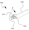
図2は錠剤カセット500のチャッキングユニット400に対向する側から見た斜視図、図3はその分解斜視図、図4はシート飛び出し防止機構5401の構成を示す斜視図、図5は錠剤カセット500の組み立て図であって、その本体上部530をカセット基部510の後方に大きく突出させた状態を示す側断面図、図6は錠剤カセット500の組み立て図であって、その本体上部530をカセット基部510上の所定位置に収容した状態を示す側断面図である。なお、以下では、錠剤カセット500のチャッキングユニット400に対向する側を前、その反対側を後という。
2 is a perspective view of the
本実施形態における錠剤カセット500は、後述する図7〜図10に示すように積載される各種PTP錠剤シート(錠剤シートに相当する。)900,900,・・・よりも若干幅広に形成されている。したがって、錠剤カセット500としては、各種PTP錠剤シート900,900,・・・の有する幅に応じて、幅寸法のみが異なるものが複数用意される。それらの具体的な構成は、いずれも図2,図3に示すように、断面凹状をなす長尺のカセット基部510と、このカセット基部510の長手方向にスライドさせて着脱自在に嵌合されるカセット本体520とからなっている。
The
カセット基部510の底板5101の裏面側には、図略の突起が前後(及び左右)にそれぞれ形成され、その底板5101の後端は上方に屈曲されて弾性を有する左右二条の舌片5102,5102が形成されている。前記底板5101の後部の表面側には断面逆凹状の支持部材5103が形成され、この支持部材5103で片持ち支持される左右二条の舌片515,515がそれぞれ前部に向かって先下がりに形成されている。なお、この舌片515,515は、前記図2に示すように、ともにカセット基部510の左右壁516,517内に配置されており、この舌片515,515で前記PTP錠剤シート900,900,・・・の端数分がチャッキングされるようになっている。ただし、前記舌片515の条数は二条に限定されず、一条でもよいし、三条以上であってもよい(この点は、他の舌片5102等についても同様である)。
On the back side of the
カセット本体520は、さらに複数のPTP錠剤シート900,900,・・・を積載可能で、かつ、その前壁下部に開放状態のシート出口を有する本体上部(薬品ストック部に相当する。)530と、この本体上部530の下部に一体となるように取り付けられた本体下部540と、この本体下部540をカセット基部510上でスライド自在に支持する支持部(レール部材に相当する。)5110とからなっている。
The
支持部5110は、前後に延びる底板5111の左右両端を上方に屈曲させて左右両側壁となし、この左右両側壁をさらに左右対称のコの字状に屈曲させてなるスライドレール5112,5112と、前記底板5111の前部に設けられ、その後方に向かって先下がりに形成されている舌片5115と、前記底板5111の後部に設けられ、その上方に向かう左右二条の舌片5116,5116とからなっている。スライドレール5112,5112のうちの一方(例えば図2中では向かって右側であり、図3中では向かって左側である。)の前端には、凹状の切り欠き部5117が形成されている。支持部5110は、カセット基部510の天井面5104に固定される。
The
本体下部540は、支持部5110のスライドレール5112,5112間に嵌合されて前後方向にスライド自在となるものであるが、その単体で見ると、図3に示すように、断面凹状の長尺形状をなした底面541上に前記本体上部530の一番下に積載された図略のPTP錠剤シートを順次に取り出すためのリンク機構550と、シート飛び出し防止機構5401とを備えている。
The main body
このシート飛び出し防止機構5401は、図4に示すように、側面視でL字状の本体部材5402と、この本体部材5402を軸心5403まわりに回転自在に軸支する支持部材5404とを有している。また、本体部材5402は、錠剤カセット500の本体下部540に固定された支持部材5404に対して向かって時計まわり(図4中のA方向)に回転可能となるように、バネ5405で弾性付勢されている。
As shown in FIG. 4, the sheet pop-
そして、図5に示すように、錠剤カセット500の本体上部530が本体下部540とともに、支持部5110のスライドレール5112上をスライドして、前記カセット基部510の後方に突出している状態(オーバーハングさせた状態)では、前記シート飛び出し機構5401の本体部材5402の前後端がともに、前記スライドレール5112上の後端側にある。したがって、このときにスライドレール5112から受ける反力により、本体部材5402の回転が規制される。これにより、本体上部530へのPTP錠剤シートの補充時にそのPTP錠剤シートが前記シート出口から前方に飛び出すことが防止されるので、その補充が容易となる。
Then, as shown in FIG. 5, the
一方、錠剤カセット500の本体上部530が本体下部540と共に、支持部5110のスライドレール5112上をスライドして、その本体上部530がカセット基部510上に完全に収容された状態となるまでは、前記シート飛び出し機構5401の本体部材5402の前後端がともに、前記スライドレール5112上に沿ってスライドする。したがって、このときにスライドレール5112から受ける反力により、本体部材5402の回転が規制される。これにより、本体上部530に補充されたPTP錠剤シートが前記シート出口から前方に飛び出すことが防止されるので、スライドのスピードを上げて、その作業効率を向上させることができる。そして、図6に示すように、錠剤カセット500の本体上部530が本体下部540と共に、支持部5110のスライドレール5112上をスライドして、その本体上部530がカセット基部510上に完全に収容された状態となると、前記シート飛び出し機構5401の本体部材5402の前端のみが、前記スライドレール5112の切り欠き部5117の上方に存することになる。このときにはスライドレール5112から受ける反力がまったくなくなるため、バネ5405の弾性付勢力で直立状態を維持する程度になる。したがって、前記本体上部530の一番下に積載された前記PTP錠剤シート900を、本体下部540のリンク機構550の働きでもって頭出ししようとすると、この頭出ししようとされるPTP錠剤シート900の先端が、前記シート飛び出し機構5401の本体部材5402の頂部付近に当接することになる。
Meanwhile, until the main body
すると、前記バネ5405の弾性付勢力に抗して、その本体部材5402が前方(図4中のA方向と逆方向)へと回転し、当該一番下に積載された前記PTP錠剤シート900が前記シート出口から頭出しされる。この頭出しされたPTP錠剤シート900は、チャッキングユニット400のチャック430で把持して容易に引き出すことができるようになる。
Then, against the elastic biasing force of the
また、本体下部540の底面541の前方よりの部分は一部切り欠かれており、図6に示すように、この切り欠き部分(嵌合孔に相当する。)547に前記舌片5115が嵌合することで、本体下部540はそのスライド範囲のうちの前端側の位置でいわゆるロック状態となる(ロック手段としての機能である)。
Further, a part from the front of the
このロック状態は、図5に示すように、本体下部540を後方へ引き出すことで、切り欠き部分547から前記舌片5115が脱出して簡単に解除される(これもロック手段としての機能である)。
As shown in FIG. 5, this locked state is easily released by pulling out the
さらに、本体下部540の底面541の前記切り欠き部分547の後方には、その底面541の幅方向に離間した位置には2個の螺子孔548,548が形成されており、この螺子孔548,548には螺子545,545が螺合されて、底面541の裏側にその先端部分がそれぞれ突出するようになっている(突片に相当する)。そして、図5で示すように、当該先端部分が前記舌片5116,5116にそれぞれ当接することで、本体下部540のスライド範囲のうちの後端側の位置が規制される(ストッパ手段としての機能である)。
Further, two
本体上部530は、本体下部540に固定されるものであるが、その本体下部540と前記支持部5110を介して、カセット本体520のカセット基部510へ組み立てられた状態では、その後部から中間部にかけてはカセット基部510の左右側壁516,517内に出没自在に配置され、その中間部から前部にかけてはカセット基部510の左右側壁516,517の上方に突出して配置される側面視L字状をなしており、当該突出させた左右両側壁5311,5312が前端で互いに内側に屈曲されることにより、所定の間隙を介して対向配置されることで、前壁531を形成している。左右両側壁5311,5312の上端同士は補強板532で互いに連結されている。
The main body
この本体上部530の後部には、棒状部材533が起伏可能に立設されており、PTP錠剤シート900,900,・・・の充填時に倒伏させて、前記前壁531間にPTP錠剤シート900,900,・・・を挟み込んだ状態で、この棒状部材533を起立させることで、各PTP錠剤シート900,900,・・・を整列させるようになっている。本体上部530の底面5301の前方に形成された四角形状の孔5302は、前記螺子545,545を挿通するためのものである。
A bar-
以下、調剤装置1の錠剤カセット500の使用方法について概略説明する。
Hereinafter, the usage method of the
ここで、図7はカセット棚600の棚板602上に複数個の錠剤カセット500が搭載されている状態を示す斜視図、図8は特定の錠剤カセット500の本体上部530を後方に引き出した状態を示す斜視図、図9は図7の状態にある錠剤カセット500のシートの頭出し前の状態を示す斜視図、図10は図7の状態にある錠剤カセット500のシートの頭出し後の状態を示す斜視図である。
Here, FIG. 7 is a perspective view showing a state in which a plurality of
まず、図7に示すように、カセット棚600の棚板602上には、多数の錠剤カセット500,500,・・・が搭載されている。この場合には、隣り合う錠剤カセット500,500が邪魔になって、例えば同図7中の中央にある特定の錠剤カセット500からPTP錠剤シート900の補充や取り出しを行うのが困難である。
7, a large number of
そこで、図8に示すように、錠剤カセット500の本体上部530を本体下部540とともに、カセット基部510の後方に引き出して、棒状部材533を後方に倒伏させることとする。このとき、前記引き出し操作をするだけで、前記舌片5115が前記切り欠き部分547から脱出する結果、簡単にロック状態が解除される。
Therefore, as shown in FIG. 8, the main body
また、錠剤カセット500の本体上部530をスライドさせて後方に引き出している間は、シート飛び出し防止機構5401の働きでもって、PTP錠剤シート900が、その前方の開口部である前記シート出口から脱落するのが防止される。
Further, while the
すなわち、前記シート飛び出し防止機構5401は、その本体部材5402が、前記スライド中は前記支持部5110のスライドレール5112で回転が規制されるとともにその頂部が、錠剤カセット500の本体上部530の一番下に積載されたPTP錠剤シート900の前端に当接するように弾性付勢されて直立状態を維持しているから、この状態では前記PTP錠剤シート900が錠剤カセット500の本体上部530の前壁下部のシート出口から飛び出すことはない。
That is, the sheet pop-
そして、棒状部材533を後方に倒伏させると、前記本体上部530が後方に開放された状態となり、この開放状態の本体上部530にPTP錠剤シート900を容易に補充あるいは取り出すことができる。
When the rod-
しかる後、再び棒状部材533を起立させて、前記錠剤カセット500の本体上部530を前方に押し戻すのであるが、このときにも、錠剤カセット500の本体上部530をスライドさせて前方に押し戻している間は、シート飛び出し防止機構5401の働きでもって、PTP錠剤シート900が、その前方の開口部である前記シート出口から脱落するのが防止される。
Thereafter, the rod-shaped
すなわち、前記シート飛び出し防止機構5401は、前記と同様に、その本体部材5402が、前記スライド中は前記支持部5110のスライドレール5112で回転が規制されるとともにその頂部が、錠剤カセット500の本体上部530の一番下に積載されたPTP錠剤シート900の前端に当接するように弾性付勢されて直立状態を維持しているから、この状態では前記PTP錠剤シート900が錠剤カセット500の本体上部530の前壁下部のシート出口から飛び出すことはない。
That is, the sheet pop-
そして、前記本体上部530とともに本体下部540が支持部5110のスライドレール5112上をスライドしてその前端に達すると、前記舌片5115が前記切り欠き部分547に嵌合する結果、簡単にロック状態となる。このときの状態は図9に示すとおりである。
When the main body
すなわち、このときには前記シート飛び出し防止機構5401の本体部材5402も前記スライドレール5112の前端の切り欠き部5117の上方に到達しているから、本体部材5402のスライドレール5112から受ける反力がまったくなくなり、前記本体部材5402はバネ5405の弾性付勢力で直立状態を維持する程度になっている。
That is, at this time, the
チャッキングユニット400は、図1に示すように、キャリッジ本体310から前方(図1中のZ方向)に延びるZキャリッジ411と、このZキャリッジ411に配置されたロータリーソレノイド420と、このロータリーソレノイド420で駆動されるチャック430と、このチャック430の左右にそれぞれ配置された横ガイド440,440と、横ガイド440,440間の下部に設けられた一次バケット450と、この一次バケット450の前部に設けられたラインセンサー460と、一次バケット450の下方に設けられたシャッター470付きの二次バケット480とを備えている。Zキャリッジ411は、いずれも図示しないサーボモータと、ボールネジと、ナットとからなっている。
As shown in FIG. 1, the
そして、PTP錠剤シート900の端数打ち抜きが不要である場合には、図示しないコントローラからの動作指令を受けて、チャッキングユニット400のチャック430が前方へ移動して、そのチャック430で直接に錠剤カセット500の押圧部材543を押圧することで、そのリンク機構550の働きでもって、押出部材546を前向きに移動させる。
If it is not necessary to punch the fraction of the
この移動された押出部材546で、錠剤カセット500の一番下側に積載されたPTP錠剤シート900の後端を押圧することにより、そのPTP錠剤シート900の先端が若干当該錠剤カセット500より突出して、いわゆる頭出しがなされるのであるが、前記一番下に積載された前記PTP錠剤シート900を、本体下部540のリンク機構550の働きでもって頭出ししようとすると、この頭出ししようとされるPTP錠剤シート900の先端が、前記シート飛び出し機構5401の本体部材5402の頂部付近に直角に当接することになる。
By pressing the rear end of the
すると、前記バネ5405の弾性付勢力に抗して、その本体部材5402が前方(図4中のA方向と逆方向)へと回転し、当該一番下に積載された前記PTP錠剤シート900が前記シート出口から頭出しされる。
Then, against the elastic biasing force of the
これにより、図10に示すように、その本体上部530に積載されたPTP錠剤シート900がその一番下側から突出するので、この突出したPTP錠剤シート900をチャッキングユニット400のチャック430でチャッキングできるようになる。
As a result, as shown in FIG. 10, the
そして、前記チャック430でその頭出しされたPTP錠剤シート900をチャッキングして前方に引っ張り出し、その引っ張り出したPTP錠剤シート900を一次バケット450内に落下させるためにチャック430によるチャッキングを解除する。Xキャリッジ300と、Yキャリッジ200とを用いて一次バケット450を二次バケット480上に移動させる。そして、一次バケット450の図示しない底部シャッターを開口して、PTP錠剤シート900を二次バケット480内に落下させる。ついで、二次バケット480の底部シャッター470を開口して、PTP錠剤シート900を搬送コンベアユニット800上に落下させる。
Then, the chucked
カッティングユニット700は、PTP錠剤シート900の端数打ち抜きをするために、図示しない縦刃と横刃とを備えている。そして、PTP錠剤シート900の端数打ち抜きが必要である場合にも、前述したように、チャッキングユニット400のチャック430で錠剤カセット500の押圧部材543を押圧してリンク機構550で押出部材546を前向きに移動させる。
The
この移動された押出部材546で、錠剤カセット500の一番下側に積載されたPTP錠剤シート900の後端を押圧することにより、そのPTP錠剤シート900の頭出しがなされる。前記チャック430でその頭出しされたPTP錠剤シート900をチャッキングして前方に引っ張り出し、今度はその引っ張り出したPTP錠剤シート900をチャッキングしたまま、カッティングユニット700に搬送する。そして、前記縦刃と横刃とを用いてPTP錠剤シート900の端数打ち抜きを行って、当該打ち抜いた端数分のPTP錠剤シート900を直接搬送コンベアユニット800上に落下させるようになっている。
By pushing the rear end of the
前記PTP錠剤シート900の端数打ち抜きを行った残部は、チャック430でチャッキングしたまま、もとの錠剤カセット500に戻すが、この場合には、PTP錠剤シート900の残部は、カセット基部510の舌片515,515下の残部収納部515aに頭出しした状態で挿入して収納される。
The remaining part of the
この残部収納部515aに収納されたPTP錠剤シート900の残部は、その後、前記チャック430でその頭出しされたPTP錠剤シート900の残部をチャッキングして前方に引っ張り出して、ラインセンサー460で形状をチェックする。そして、PTP錠剤シート900の残部のさらなる端数打ち抜きが不要である場合には、そのPTP錠剤シート900の残部を、一次バケット450内に落下させるためにチャック430によるチャッキングを解除する。Xキャリッジ300と、Yキャリッジ200を用いて一次バケット450を二次バケット480上に移動させる。ついで、一次バケット450の図示しない底部シャッターを開口して、PTP錠剤シート900を二次バケット480内に落下させる。ついで、二次バケット480の底部シャッター470を開口して、PTP錠剤シート900を搬送コンベアユニット800上に落下させる。
The remaining portion of the
一方、PTP錠剤シート900の残部のさらなる端数打ち抜きが必要である場合にも、前述したように、前記チャック430でカセット基部510の舌片515,515下の残部収納部515aから、その頭出しされたPTP錠剤シート900の残部をチャッキングして前方に引っ張り出す。その引っ張り出したPTP錠剤シート900の残部をチャッキングしたまま、カッティングユニット700に搬送する。そして、前記縦刃と横刃とを用いてPTP錠剤シート900残部のさらなる端数打ち抜きを行って、当該打ち抜いたさらなる端数分のPTP錠剤シート900を直接搬送コンベアユニット800上に落下させる。
On the other hand, even when it is necessary to punch the remaining fraction of the remaining portion of the
一方、前記PTP錠剤シート900のさらなる端数打ち抜きを行った残部は、チャック430でチャッキングしたまま、もとの錠剤カセット500に戻すが、この場合も、PTP錠剤シート900の残部は、カセット基部510の舌片515,515下の残部収納部515aに頭出しした状態で挿入して収納される。
On the other hand, the remaining part of the
このようにして、錠剤カセット500に積載されたPTP錠剤シート900はその端数まで無駄なく調剤に供されることとなる。
In this way, the
搬送コンベアユニット800は、ローラ群等801と、このローラ群等801で前後・左右方向に移動される錠剤取出バケット802,802とを備えている。そして、前記二次バケット480からシャッター470を介して落下したPTP錠剤シート900又はその残部は、ローラ群等801で前後・左右方向に移動され、錠剤取出バケット802,802のいずれかに落下されるようになっている。
The
一方、前記カッティングユニット700から落下したPTP錠剤シート900の残部又はさらなる残部も、同様に、ローラ群等801で前後・左右方向に移動され、錠剤取出バケット802,802のいずれかに落下される。
On the other hand, the remaining portion or further remaining portion of the
このようにして、錠剤取出バケット802,802には、調剤されたPTP錠剤シート900又はその残部が収納されるようになっている。
In this way, the dispensed
この実施形態によれば、錠剤カセット500に、本体上部530を本体下部540とともに前後方向にスライド自在に支持する支持部5110が備えられているので、錠剤カセット500の本体上部530である薬剤ストック部を前後方向にスライドさせてカセット基部510からある程度だけ離間させた位置にもってくることができる。したがって、錠剤カセット500を収納したカセット棚600の棚板602が複数段あっても、錠剤カセット500の前後方向に本体上部530をスライドさせることにより、その上方のカセット棚600の棚板602を回避できる。このため、錠剤カセット500の上方からPTP錠剤シート900の補充や取り出し作業を容易に行うことができるようになる。
According to this embodiment, since the
特に、カセット棚600の棚板602上で隣り合う錠剤カセット500,50を互いに密着させて設置している場合であっても、錠剤カセット500の前後方向に本体上部530をスライドさせることにより、隣り合う錠剤カセット500,500が邪魔にならなくなって、特定の錠剤カセット500からPTP錠剤シート900の補充や取り出し作業を容易に行うことができるようになる。
In particular, even when the
なお、上記実施形態では、左右に2台のカセット棚600,600を配置しているが、前後に配置することとしてもよいし、1台、或いは3台以上のカセット棚を配置することとしてもよい。その場合には、各キャリッジ、チャッキングユニット、カッティングユニット等の台数もこれに対応したものとするのが作業効率の点から好ましい。
In the above embodiment, the two
また、上記実施形態では、シート飛び出し防止機構5401は、図4に示すように、上部が前下がりとなっている本体部材5402を有しているが、これに代えて、図11に示すように、上部が後下がりとなっている本体部材5402aを有するシート飛び出し防止機構5401aを使用することとしてもよい。このシート飛び出し防止機構5401aによれば、錠剤カセット500の本体上部530の一番下に積載されたPTP錠剤シート900を、本体下部540のリンク機構550の働きでもって頭出しをしようとすると、この頭出ししようとされるPTP錠剤シート900の先端が、前記シート飛び出し機構5401aの本体部材5402aの頂部付近に鈍角で当接することとなる。したがって、前記シート防止機構5401のように、その本体部材5402の頂部付近に直角に当接する場合に比べて、頭出ししたPTP錠剤シート900が本体部材5402aを回転させやすくなる。
Further, in the above embodiment, the sheet pop-
また、このシート飛び出し防止機構5401aの本体部材5402aをPTP錠剤シート900が通過する際に、その角部が鈍角であるため、直角の角部を有する前記シート飛び出し防止機構5401の本体部材5402をPTP錠剤シート900が通過する場合に比べて、PTP錠剤シート900に傷がつきにくくなる。
Further, when the
また、上記実施形態では、図2に示すように、本体上部530は、後端から前方に向けて部分的に切り欠いた左右両側壁5311,5312を備えているので、錠剤カセット500の前後方向に本体上部530をスライドさせて後方に引き出した上、この本体上部530の左右両側壁5311,5312の切り欠かれた部分からPTP錠剤シート(薬品に相当する。)900を搬入して該左右両側壁5311,5312で案内することで、そのPTP錠剤シート900を錠剤カセット500の本体上部530にさらに補充しやすくなる。また、前記左右両側壁5311,5312の切り欠かれた部分から、前記錠剤カセット500に補充されたPTP錠剤シート900を、その錠剤カセット500の本体上部530の外部へさらに取り出しやすくなる。
Further, in the above embodiment, as shown in FIG. 2, the main body
しかしながら、図12及び図13(図12において棒状部材533を省略したもの)に示すように、左右両側壁5311,5312を切り欠いた残りの部分の上端P,Qが、PTP錠剤シート900に平行である場合には、そのPTP錠剤シート900と当該残りの部分の上端P,Qとが線接触となる。このため、PTP錠剤シート900の左右いずれか一方が当該残りの部分の上端P,Qに乗りかかって底面5301に対して横傾斜状態となり、このPTP錠剤シート900が錠剤カセット500の本体上部530内の所定位置に収納されなくなる、いわゆる錠剤シートの横ブリッジが発生することがある。そして、この横ブリッジにより、一番下のPTP錠剤シート900の後端に押出部材(図略)がかかりにくくなって、PTP錠剤シート900の錠剤カセット500からの払い出しを阻害するおそれがあった。
However, as shown in FIGS. 12 and 13 (in which the rod-
図14は他の錠剤カセットの本体上部を後方に引き出した状態を示す斜視図、図15は他の錠剤カセットの本体上部をカセット基部に収容した状態を示す斜視図である。 FIG. 14 is a perspective view showing a state where the upper part of the main body of another tablet cassette is pulled out rearward, and FIG. 15 is a perspective view showing a state where the upper part of the main body of another tablet cassette is housed in the cassette base.
そこで、例えば図15に示すように、カセット基部510は、本体上部530を収容するときに、該本体上部530に搭載されたPTP錠剤シート900が、その底面5301と平行でかつ左右両側面5311,5312間に収まるような姿勢(所定姿勢に相当する。)となるように該PTP錠剤シート900を案内する左右両側壁516a,517aを形成することが好ましい。この左右両側壁516a,517aは、例えば略四角形状であり、本体上部530を完全に収容した状態で、該本体上部530の左右両側壁5311,5312の切り欠いた部分を左右両側から完全に覆うものである。
Therefore, for example, as shown in FIG. 15, when the
そして、図14に示すように、錠剤カセット500の前後方向に本体上部530をスライドさせて後方に引き出したときには、PTP錠剤シート900が左右両側壁5311,5312の残りの部分の上端P,Qに乗りかかって横傾斜状態となっていたとしても、図15に示すように、本体上部530をスライドさせて前方のカセット基部510に収容させるときには、カセット基部510の左右両側壁516a,517aでその横傾斜状態のPTP錠剤シート900が案内されて前記姿勢になる。
As shown in FIG. 14, when the main body
このようにして、本体上部530の全体にわたり、PTP錠剤シート900の横ブリッジを簡単かつ確実に解消することができる。
In this way, the horizontal bridge of the
また、上記実施形態では、各PTP錠剤カセット500,500,・・・は、カセット棚600の棚板602上に、該各PTP錠剤カセット500,500,・・・の幅方向に列設されているが、この棚板は静止した平板状のものに限定されず、例えば所定の軸心まわりに回転する円筒形状のものであってもよい。その場合には、チャッキングユニット400を、この回転する棚板上に搭載された各PTP錠剤カセット500,500,・・・に対して相対移動させることで足りる。
In the above embodiment, the
1 調剤装置
100 装置本体
200 Yキャリッジ
300 Xキャリッジ
400 チャッキングユニット
411 Zキャリッジ
420 ロータリーソレノイド
430 チャック
500 錠剤カセット
510 カセット基部
5110 支持部(レール部材に相当する。)
5112 スライドレール
5115 舌片(ロック手段に相当する。)
5116 舌片(ストッパ手段に相当する。)
5117 切り欠き部
516,517 カセット基部の左右両側壁
516a,517a カセット基部の左右両側壁
520 カセット本体
530 本体上部(薬品ストック部に相当する。)
5301 本体上部の底面
5311,5312 本体上部の左右両側壁
540 本体下部
543 押圧部材
545 螺子(突片、ストッパ手段に相当する。)
546 押出部材
547 切り欠き部分(嵌合孔、ロック手段に相当する。)
548 螺子孔
5401,5401a シート飛び出し防止機構
5402,5402a 本体部材
550 リンク機構
600 カセット棚
602 棚板
700 カッティングユニット
800 搬送コンベアユニット
900 PTP錠剤シート(錠剤シート、薬品に相当する。)
1
5112
5116 Tongue piece (corresponding to stopper means)
5117
5301
546 Extruding
548
Claims (7)
前記薬品ストック部は、後端から前方に向けて部分的に切り欠いた左右両側壁を備え、
前記カセット基部は、前記薬品ストック部を前後方向にスライド自在に支持するレール部材を備えるとともに、前記薬品ストック部を収容するときに、該薬品ストック部に搭載された錠剤シートが所定姿勢になるように該錠剤シートを案内する左右両側壁を備えたことを特徴とする調剤装置の薬品ストック構造。 A drug stock structure of a dispensing device having a drug stock part for stocking a tablet sheet containing a drug on a cassette base of a tablet cassette,
The drug stock portion includes left and right side walls partially cut away from the rear end toward the front,
The cassette base includes a rail member that slidably supports the medicine stock portion in the front-rear direction, and the tablet sheet mounted on the medicine stock portion is in a predetermined posture when the medicine stock portion is accommodated. A drug stock structure for a dispensing device, comprising left and right side walls for guiding the tablet sheet.
Priority Applications (1)
| Application Number | Priority Date | Filing Date | Title |
|---|---|---|---|
| JP2012119234A JP5357302B2 (en) | 2007-04-09 | 2012-05-25 | Dispensing equipment chemical stock structure |
Applications Claiming Priority (3)
| Application Number | Priority Date | Filing Date | Title |
|---|---|---|---|
| JP2007102248 | 2007-04-09 | ||
| JP2007102248 | 2007-04-09 | ||
| JP2012119234A JP5357302B2 (en) | 2007-04-09 | 2012-05-25 | Dispensing equipment chemical stock structure |
Related Parent Applications (1)
| Application Number | Title | Priority Date | Filing Date |
|---|---|---|---|
| JP2007260511A Division JP5154882B2 (en) | 2007-04-09 | 2007-10-04 | Dispensing equipment chemical stock structure |
Publications (2)
| Publication Number | Publication Date |
|---|---|
| JP2012176280A JP2012176280A (en) | 2012-09-13 |
| JP5357302B2 true JP5357302B2 (en) | 2013-12-04 |
Family
ID=40140551
Family Applications (2)
| Application Number | Title | Priority Date | Filing Date |
|---|---|---|---|
| JP2007260511A Active JP5154882B2 (en) | 2007-04-09 | 2007-10-04 | Dispensing equipment chemical stock structure |
| JP2012119234A Active JP5357302B2 (en) | 2007-04-09 | 2012-05-25 | Dispensing equipment chemical stock structure |
Family Applications Before (1)
| Application Number | Title | Priority Date | Filing Date |
|---|---|---|---|
| JP2007260511A Active JP5154882B2 (en) | 2007-04-09 | 2007-10-04 | Dispensing equipment chemical stock structure |
Country Status (1)
| Country | Link |
|---|---|
| JP (2) | JP5154882B2 (en) |
Families Citing this family (4)
| Publication number | Priority date | Publication date | Assignee | Title |
|---|---|---|---|---|
| JP5344959B2 (en) * | 2009-03-12 | 2013-11-20 | 高園産業株式会社 | Dispensing device sheet extrusion mechanism |
| JP5430346B2 (en) * | 2009-10-28 | 2014-02-26 | 高園産業株式会社 | Drug stock structure of dispensing equipment |
| JP6075727B2 (en) * | 2013-01-16 | 2017-02-08 | 株式会社トーショー | PTP cassette |
| JP6075728B2 (en) * | 2013-04-03 | 2017-02-08 | 株式会社トーショー | PTP cassette |
Family Cites Families (2)
| Publication number | Priority date | Publication date | Assignee | Title |
|---|---|---|---|---|
| JPH0554223U (en) * | 1991-02-25 | 1993-07-20 | 株式会社コパル | Dispenser tablet case |
| JP3892946B2 (en) * | 1997-06-26 | 2007-03-14 | 株式会社湯山製作所 | Tablet blister pack storage container |
-
2007
- 2007-10-04 JP JP2007260511A patent/JP5154882B2/en active Active
-
2012
- 2012-05-25 JP JP2012119234A patent/JP5357302B2/en active Active
Also Published As
| Publication number | Publication date |
|---|---|
| JP5154882B2 (en) | 2013-02-27 |
| JP2008279241A (en) | 2008-11-20 |
| JP2012176280A (en) | 2012-09-13 |
Similar Documents
| Publication | Publication Date | Title |
|---|---|---|
| JP5357302B2 (en) | Dispensing equipment chemical stock structure | |
| JP2006219299A (en) | Article delivery device and method | |
| JP4871695B2 (en) | Dispensing device | |
| JP5134941B2 (en) | Sheet stacking structure of dispensing device | |
| JP5430346B2 (en) | Drug stock structure of dispensing equipment | |
| JP5102608B2 (en) | Dispensing equipment chemical stock structure | |
| JP6283702B2 (en) | Dispensing device | |
| JP4830979B2 (en) | Vending machine product storage device | |
| JP2008299805A (en) | Commodity storage device of vending machine | |
| JP2014194677A (en) | Automatic dispenser | |
| JP4965218B2 (en) | Dispensing device cassette fixing structure | |
| JP6118977B2 (en) | Dispensing device medicine dispensing mechanism | |
| JP2010207361A (en) | Medicine stock structure for tablet dispenser | |
| JP4929021B2 (en) | Dispensing device chucking mechanism | |
| JP2009089749A (en) | Cutting method and cutting mechanism for dispensing apparatus | |
| JP5867864B2 (en) | Dispensing device | |
| JP5357303B2 (en) | Dispensing device sheet removal mechanism | |
| JP5132974B2 (en) | Earless sheet handling method and apparatus for dispensing device | |
| JP6142252B2 (en) | Dispensing device medicine dispensing mechanism | |
| JP5102607B2 (en) | Dispensing device cassette shelf structure | |
| JP5430347B2 (en) | Drug stock structure of dispensing equipment | |
| JP5344959B2 (en) | Dispensing device sheet extrusion mechanism | |
| JP2014151028A (en) | Medicine dispensing method, medicine storage cassette, and medicine dispensing device | |
| JP2009089747A (en) | Sheet ejection mechanism of dispensing apparatus and its method | |
| JP2006109858A (en) | Dispensing medicament put-out device |
Legal Events
| Date | Code | Title | Description |
|---|---|---|---|
| TRDD | Decision of grant or rejection written | ||
| A01 | Written decision to grant a patent or to grant a registration (utility model) |
Free format text: JAPANESE INTERMEDIATE CODE: A01 Effective date: 20130827 |
|
| A61 | First payment of annual fees (during grant procedure) |
Free format text: JAPANESE INTERMEDIATE CODE: A61 Effective date: 20130829 |
|
| R150 | Certificate of patent or registration of utility model |
Ref document number: 5357302 Country of ref document: JP Free format text: JAPANESE INTERMEDIATE CODE: R150 Free format text: JAPANESE INTERMEDIATE CODE: R150 |
|
| S533 | Written request for registration of change of name |
Free format text: JAPANESE INTERMEDIATE CODE: R313533 |
|
| R350 | Written notification of registration of transfer |
Free format text: JAPANESE INTERMEDIATE CODE: R350 |
|
| R250 | Receipt of annual fees |
Free format text: JAPANESE INTERMEDIATE CODE: R250 |
|
| R250 | Receipt of annual fees |
Free format text: JAPANESE INTERMEDIATE CODE: R250 |
|
| R250 | Receipt of annual fees |
Free format text: JAPANESE INTERMEDIATE CODE: R250 |
|
| R250 | Receipt of annual fees |
Free format text: JAPANESE INTERMEDIATE CODE: R250 |
|
| R250 | Receipt of annual fees |
Free format text: JAPANESE INTERMEDIATE CODE: R250 |
|
| R250 | Receipt of annual fees |
Free format text: JAPANESE INTERMEDIATE CODE: R250 |
|
| R250 | Receipt of annual fees |
Free format text: JAPANESE INTERMEDIATE CODE: R250 |
|
| R250 | Receipt of annual fees |
Free format text: JAPANESE INTERMEDIATE CODE: R250 |