JP5350655B2 - Semiconductor device - Google Patents
Semiconductor device Download PDFInfo
- Publication number
- JP5350655B2 JP5350655B2 JP2008073142A JP2008073142A JP5350655B2 JP 5350655 B2 JP5350655 B2 JP 5350655B2 JP 2008073142 A JP2008073142 A JP 2008073142A JP 2008073142 A JP2008073142 A JP 2008073142A JP 5350655 B2 JP5350655 B2 JP 5350655B2
- Authority
- JP
- Japan
- Prior art keywords
- semiconductor film
- transistor
- insulating film
- film
- semiconductor
- Prior art date
- Legal status (The legal status is an assumption and is not a legal conclusion. Google has not performed a legal analysis and makes no representation as to the accuracy of the status listed.)
- Expired - Fee Related
Links
- 239000004065 semiconductor Substances 0.000 title claims abstract description 403
- 239000000758 substrate Substances 0.000 claims abstract description 338
- 239000012535 impurity Substances 0.000 claims description 95
- 230000015572 biosynthetic process Effects 0.000 claims description 65
- 238000000034 method Methods 0.000 abstract description 77
- 238000004519 manufacturing process Methods 0.000 abstract description 33
- 230000008569 process Effects 0.000 abstract description 7
- 239000002585 base Substances 0.000 description 128
- 239000010410 layer Substances 0.000 description 61
- 239000007789 gas Substances 0.000 description 57
- 238000010438 heat treatment Methods 0.000 description 41
- VYPSYNLAJGMNEJ-UHFFFAOYSA-N Silicium dioxide Chemical compound O=[Si]=O VYPSYNLAJGMNEJ-UHFFFAOYSA-N 0.000 description 35
- 229910052814 silicon oxide Inorganic materials 0.000 description 34
- XUIMIQQOPSSXEZ-UHFFFAOYSA-N Silicon Chemical compound [Si] XUIMIQQOPSSXEZ-UHFFFAOYSA-N 0.000 description 33
- 229910052710 silicon Inorganic materials 0.000 description 33
- 239000010703 silicon Substances 0.000 description 33
- 229910052581 Si3N4 Inorganic materials 0.000 description 31
- HQVNEWCFYHHQES-UHFFFAOYSA-N silicon nitride Chemical compound N12[Si]34N5[Si]62N3[Si]51N64 HQVNEWCFYHHQES-UHFFFAOYSA-N 0.000 description 31
- 230000007547 defect Effects 0.000 description 30
- 239000013078 crystal Substances 0.000 description 28
- 239000001257 hydrogen Substances 0.000 description 25
- 229910052739 hydrogen Inorganic materials 0.000 description 25
- IJGRMHOSHXDMSA-UHFFFAOYSA-N Atomic nitrogen Chemical compound N#N IJGRMHOSHXDMSA-UHFFFAOYSA-N 0.000 description 24
- 238000005530 etching Methods 0.000 description 23
- UFHFLCQGNIYNRP-UHFFFAOYSA-N Hydrogen Chemical compound [H][H] UFHFLCQGNIYNRP-UHFFFAOYSA-N 0.000 description 21
- 239000001301 oxygen Substances 0.000 description 20
- 229910052760 oxygen Inorganic materials 0.000 description 20
- QVGXLLKOCUKJST-UHFFFAOYSA-N atomic oxygen Chemical compound [O] QVGXLLKOCUKJST-UHFFFAOYSA-N 0.000 description 19
- 239000000463 material Substances 0.000 description 17
- BLRPTPMANUNPDV-UHFFFAOYSA-N Silane Chemical compound [SiH4] BLRPTPMANUNPDV-UHFFFAOYSA-N 0.000 description 15
- 229910000077 silane Inorganic materials 0.000 description 15
- QGZKDVFQNNGYKY-UHFFFAOYSA-N Ammonia Chemical compound N QGZKDVFQNNGYKY-UHFFFAOYSA-N 0.000 description 14
- 230000006870 function Effects 0.000 description 14
- 239000010936 titanium Substances 0.000 description 13
- MWUXSHHQAYIFBG-UHFFFAOYSA-N Nitric oxide Chemical compound O=[N] MWUXSHHQAYIFBG-UHFFFAOYSA-N 0.000 description 12
- BOTDANWDWHJENH-UHFFFAOYSA-N Tetraethyl orthosilicate Chemical compound CCO[Si](OCC)(OCC)OCC BOTDANWDWHJENH-UHFFFAOYSA-N 0.000 description 12
- 229910052782 aluminium Inorganic materials 0.000 description 12
- XAGFODPZIPBFFR-UHFFFAOYSA-N aluminium Chemical compound [Al] XAGFODPZIPBFFR-UHFFFAOYSA-N 0.000 description 12
- 229910052751 metal Inorganic materials 0.000 description 12
- 239000002184 metal Substances 0.000 description 12
- 229910052757 nitrogen Inorganic materials 0.000 description 12
- 238000005268 plasma chemical vapour deposition Methods 0.000 description 12
- 238000005229 chemical vapour deposition Methods 0.000 description 11
- 230000003071 parasitic effect Effects 0.000 description 11
- 238000009832 plasma treatment Methods 0.000 description 11
- PXHVJJICTQNCMI-UHFFFAOYSA-N Nickel Chemical compound [Ni] PXHVJJICTQNCMI-UHFFFAOYSA-N 0.000 description 10
- RTAQQCXQSZGOHL-UHFFFAOYSA-N Titanium Chemical compound [Ti] RTAQQCXQSZGOHL-UHFFFAOYSA-N 0.000 description 10
- 239000000126 substance Substances 0.000 description 10
- 229910052719 titanium Inorganic materials 0.000 description 10
- 230000004888 barrier function Effects 0.000 description 9
- -1 hydrogen ions Chemical class 0.000 description 9
- 230000001590 oxidative effect Effects 0.000 description 9
- 239000011148 porous material Substances 0.000 description 9
- CSDREXVUYHZDNP-UHFFFAOYSA-N alumanylidynesilicon Chemical compound [Al].[Si] CSDREXVUYHZDNP-UHFFFAOYSA-N 0.000 description 8
- 238000005984 hydrogenation reaction Methods 0.000 description 8
- 229910052750 molybdenum Inorganic materials 0.000 description 8
- 239000011733 molybdenum Substances 0.000 description 8
- 150000001282 organosilanes Chemical class 0.000 description 8
- 238000000059 patterning Methods 0.000 description 8
- ZOKXTWBITQBERF-UHFFFAOYSA-N Molybdenum Chemical compound [Mo] ZOKXTWBITQBERF-UHFFFAOYSA-N 0.000 description 7
- 229910021529 ammonia Inorganic materials 0.000 description 7
- 238000009413 insulation Methods 0.000 description 7
- 150000002500 ions Chemical class 0.000 description 7
- 238000000926 separation method Methods 0.000 description 7
- 229910021332 silicide Inorganic materials 0.000 description 7
- FVBUAEGBCNSCDD-UHFFFAOYSA-N silicide(4-) Chemical compound [Si-4] FVBUAEGBCNSCDD-UHFFFAOYSA-N 0.000 description 7
- 229910052721 tungsten Inorganic materials 0.000 description 7
- 239000010937 tungsten Substances 0.000 description 7
- WZJUBBHODHNQPW-UHFFFAOYSA-N 2,4,6,8-tetramethyl-1,3,5,7,2$l^{3},4$l^{3},6$l^{3},8$l^{3}-tetraoxatetrasilocane Chemical compound C[Si]1O[Si](C)O[Si](C)O[Si](C)O1 WZJUBBHODHNQPW-UHFFFAOYSA-N 0.000 description 6
- JBRZTFJDHDCESZ-UHFFFAOYSA-N AsGa Chemical compound [As]#[Ga] JBRZTFJDHDCESZ-UHFFFAOYSA-N 0.000 description 6
- 229910001218 Gallium arsenide Inorganic materials 0.000 description 6
- GPXJNWSHGFTCBW-UHFFFAOYSA-N Indium phosphide Chemical compound [In]#P GPXJNWSHGFTCBW-UHFFFAOYSA-N 0.000 description 6
- 229910000577 Silicon-germanium Inorganic materials 0.000 description 6
- LEVVHYCKPQWKOP-UHFFFAOYSA-N [Si].[Ge] Chemical compound [Si].[Ge] LEVVHYCKPQWKOP-UHFFFAOYSA-N 0.000 description 6
- 230000001133 acceleration Effects 0.000 description 6
- 229910052732 germanium Inorganic materials 0.000 description 6
- GNPVGFCGXDBREM-UHFFFAOYSA-N germanium atom Chemical compound [Ge] GNPVGFCGXDBREM-UHFFFAOYSA-N 0.000 description 6
- 238000002513 implantation Methods 0.000 description 6
- HMMGMWAXVFQUOA-UHFFFAOYSA-N octamethylcyclotetrasiloxane Chemical compound C[Si]1(C)O[Si](C)(C)O[Si](C)(C)O[Si](C)(C)O1 HMMGMWAXVFQUOA-UHFFFAOYSA-N 0.000 description 6
- BASFCYQUMIYNBI-UHFFFAOYSA-N platinum Chemical compound [Pt] BASFCYQUMIYNBI-UHFFFAOYSA-N 0.000 description 6
- 229920005989 resin Polymers 0.000 description 6
- 239000011347 resin Substances 0.000 description 6
- CZDYPVPMEAXLPK-UHFFFAOYSA-N tetramethylsilane Chemical compound C[Si](C)(C)C CZDYPVPMEAXLPK-UHFFFAOYSA-N 0.000 description 6
- WFKWXMTUELFFGS-UHFFFAOYSA-N tungsten Chemical compound [W] WFKWXMTUELFFGS-UHFFFAOYSA-N 0.000 description 6
- 150000001875 compounds Chemical class 0.000 description 5
- 239000010949 copper Substances 0.000 description 5
- 238000010586 diagram Methods 0.000 description 5
- KPUWHANPEXNPJT-UHFFFAOYSA-N disiloxane Chemical class [SiH3]O[SiH3] KPUWHANPEXNPJT-UHFFFAOYSA-N 0.000 description 5
- 238000011049 filling Methods 0.000 description 5
- 239000011261 inert gas Substances 0.000 description 5
- 150000004767 nitrides Chemical class 0.000 description 5
- 238000004544 sputter deposition Methods 0.000 description 5
- 229910052715 tantalum Inorganic materials 0.000 description 5
- GUVRBAGPIYLISA-UHFFFAOYSA-N tantalum atom Chemical compound [Ta] GUVRBAGPIYLISA-UHFFFAOYSA-N 0.000 description 5
- 238000001947 vapour-phase growth Methods 0.000 description 5
- ZOXJGFHDIHLPTG-UHFFFAOYSA-N Boron Chemical compound [B] ZOXJGFHDIHLPTG-UHFFFAOYSA-N 0.000 description 4
- 239000003570 air Substances 0.000 description 4
- 229910045601 alloy Inorganic materials 0.000 description 4
- 239000000956 alloy Substances 0.000 description 4
- 229910052796 boron Inorganic materials 0.000 description 4
- 230000008859 change Effects 0.000 description 4
- 239000011651 chromium Substances 0.000 description 4
- 239000011521 glass Substances 0.000 description 4
- 230000010354 integration Effects 0.000 description 4
- 229910052759 nickel Inorganic materials 0.000 description 4
- 239000012071 phase Substances 0.000 description 4
- 239000002356 single layer Substances 0.000 description 4
- YCKRFDGAMUMZLT-UHFFFAOYSA-N Fluorine atom Chemical compound [F] YCKRFDGAMUMZLT-UHFFFAOYSA-N 0.000 description 3
- KDLHZDBZIXYQEI-UHFFFAOYSA-N Palladium Chemical compound [Pd] KDLHZDBZIXYQEI-UHFFFAOYSA-N 0.000 description 3
- OAICVXFJPJFONN-UHFFFAOYSA-N Phosphorus Chemical compound [P] OAICVXFJPJFONN-UHFFFAOYSA-N 0.000 description 3
- NRTOMJZYCJJWKI-UHFFFAOYSA-N Titanium nitride Chemical compound [Ti]#N NRTOMJZYCJJWKI-UHFFFAOYSA-N 0.000 description 3
- 238000005411 Van der Waals force Methods 0.000 description 3
- 239000005407 aluminoborosilicate glass Substances 0.000 description 3
- 239000005354 aluminosilicate glass Substances 0.000 description 3
- 238000004458 analytical method Methods 0.000 description 3
- 238000001505 atmospheric-pressure chemical vapour deposition Methods 0.000 description 3
- 229910052788 barium Inorganic materials 0.000 description 3
- DSAJWYNOEDNPEQ-UHFFFAOYSA-N barium atom Chemical compound [Ba] DSAJWYNOEDNPEQ-UHFFFAOYSA-N 0.000 description 3
- 239000005388 borosilicate glass Substances 0.000 description 3
- 238000004891 communication Methods 0.000 description 3
- 229910052802 copper Inorganic materials 0.000 description 3
- 239000011737 fluorine Substances 0.000 description 3
- 229910052731 fluorine Inorganic materials 0.000 description 3
- FFUAGWLWBBFQJT-UHFFFAOYSA-N hexamethyldisilazane Chemical compound C[Si](C)(C)N[Si](C)(C)C FFUAGWLWBBFQJT-UHFFFAOYSA-N 0.000 description 3
- 239000011810 insulating material Substances 0.000 description 3
- 239000010955 niobium Substances 0.000 description 3
- 238000005121 nitriding Methods 0.000 description 3
- 239000011368 organic material Substances 0.000 description 3
- 229910052698 phosphorus Inorganic materials 0.000 description 3
- 239000011574 phosphorus Substances 0.000 description 3
- 238000005498 polishing Methods 0.000 description 3
- 239000010453 quartz Substances 0.000 description 3
- 230000009467 reduction Effects 0.000 description 3
- 229910052594 sapphire Inorganic materials 0.000 description 3
- 239000010980 sapphire Substances 0.000 description 3
- 230000008054 signal transmission Effects 0.000 description 3
- 239000002210 silicon-based material Substances 0.000 description 3
- 238000002230 thermal chemical vapour deposition Methods 0.000 description 3
- QQQSFSZALRVCSZ-UHFFFAOYSA-N triethoxysilane Chemical compound CCO[SiH](OCC)OCC QQQSFSZALRVCSZ-UHFFFAOYSA-N 0.000 description 3
- OKTJSMMVPCPJKN-UHFFFAOYSA-N Carbon Chemical compound [C] OKTJSMMVPCPJKN-UHFFFAOYSA-N 0.000 description 2
- VYZAMTAEIAYCRO-UHFFFAOYSA-N Chromium Chemical compound [Cr] VYZAMTAEIAYCRO-UHFFFAOYSA-N 0.000 description 2
- RYGMFSIKBFXOCR-UHFFFAOYSA-N Copper Chemical compound [Cu] RYGMFSIKBFXOCR-UHFFFAOYSA-N 0.000 description 2
- 229910052779 Neodymium Inorganic materials 0.000 description 2
- 239000004642 Polyimide Substances 0.000 description 2
- 125000000217 alkyl group Chemical group 0.000 description 2
- 150000004945 aromatic hydrocarbons Chemical class 0.000 description 2
- 229910052799 carbon Inorganic materials 0.000 description 2
- 239000000460 chlorine Substances 0.000 description 2
- 229910052804 chromium Inorganic materials 0.000 description 2
- 229910017052 cobalt Inorganic materials 0.000 description 2
- 239000010941 cobalt Substances 0.000 description 2
- GUTLYIVDDKVIGB-UHFFFAOYSA-N cobalt atom Chemical compound [Co] GUTLYIVDDKVIGB-UHFFFAOYSA-N 0.000 description 2
- 230000006378 damage Effects 0.000 description 2
- 230000000694 effects Effects 0.000 description 2
- 230000005674 electromagnetic induction Effects 0.000 description 2
- 239000010931 gold Substances 0.000 description 2
- 238000009616 inductively coupled plasma Methods 0.000 description 2
- 238000002955 isolation Methods 0.000 description 2
- 239000007788 liquid Substances 0.000 description 2
- 230000007257 malfunction Effects 0.000 description 2
- 239000011572 manganese Substances 0.000 description 2
- 239000007769 metal material Substances 0.000 description 2
- QEFYFXOXNSNQGX-UHFFFAOYSA-N neodymium atom Chemical compound [Nd] QEFYFXOXNSNQGX-UHFFFAOYSA-N 0.000 description 2
- 229910021334 nickel silicide Inorganic materials 0.000 description 2
- RUFLMLWJRZAWLJ-UHFFFAOYSA-N nickel silicide Chemical compound [Ni]=[Si]=[Ni] RUFLMLWJRZAWLJ-UHFFFAOYSA-N 0.000 description 2
- 230000003647 oxidation Effects 0.000 description 2
- 238000007254 oxidation reaction Methods 0.000 description 2
- TWNQGVIAIRXVLR-UHFFFAOYSA-N oxo(oxoalumanyloxy)alumane Chemical compound O=[Al]O[Al]=O TWNQGVIAIRXVLR-UHFFFAOYSA-N 0.000 description 2
- 229910052697 platinum Inorganic materials 0.000 description 2
- 229910021420 polycrystalline silicon Inorganic materials 0.000 description 2
- 229920001721 polyimide Polymers 0.000 description 2
- 150000003254 radicals Chemical class 0.000 description 2
- 239000005368 silicate glass Substances 0.000 description 2
- LIVNPJMFVYWSIS-UHFFFAOYSA-N silicon monoxide Chemical class [Si-]#[O+] LIVNPJMFVYWSIS-UHFFFAOYSA-N 0.000 description 2
- 238000003746 solid phase reaction Methods 0.000 description 2
- 125000001424 substituent group Chemical group 0.000 description 2
- MZLGASXMSKOWSE-UHFFFAOYSA-N tantalum nitride Chemical compound [Ta]#N MZLGASXMSKOWSE-UHFFFAOYSA-N 0.000 description 2
- XLYOFNOQVPJJNP-UHFFFAOYSA-N water Chemical compound O XLYOFNOQVPJJNP-UHFFFAOYSA-N 0.000 description 2
- ZAMOUSCENKQFHK-UHFFFAOYSA-N Chlorine atom Chemical compound [Cl] ZAMOUSCENKQFHK-UHFFFAOYSA-N 0.000 description 1
- 239000004593 Epoxy Substances 0.000 description 1
- PWHULOQIROXLJO-UHFFFAOYSA-N Manganese Chemical compound [Mn] PWHULOQIROXLJO-UHFFFAOYSA-N 0.000 description 1
- 229910005883 NiSi Inorganic materials 0.000 description 1
- 239000004952 Polyamide Substances 0.000 description 1
- 229910003902 SiCl 4 Inorganic materials 0.000 description 1
- BQCADISMDOOEFD-UHFFFAOYSA-N Silver Chemical compound [Ag] BQCADISMDOOEFD-UHFFFAOYSA-N 0.000 description 1
- 229910002808 Si–O–Si Inorganic materials 0.000 description 1
- GDFCWFBWQUEQIJ-UHFFFAOYSA-N [B].[P] Chemical compound [B].[P] GDFCWFBWQUEQIJ-UHFFFAOYSA-N 0.000 description 1
- NIXOWILDQLNWCW-UHFFFAOYSA-N acrylic acid group Chemical group C(C=C)(=O)O NIXOWILDQLNWCW-UHFFFAOYSA-N 0.000 description 1
- 229910052783 alkali metal Inorganic materials 0.000 description 1
- 150000001340 alkali metals Chemical class 0.000 description 1
- 229910052784 alkaline earth metal Inorganic materials 0.000 description 1
- 150000001342 alkaline earth metals Chemical class 0.000 description 1
- PNEYBMLMFCGWSK-UHFFFAOYSA-N aluminium oxide Inorganic materials [O-2].[O-2].[O-2].[Al+3].[Al+3] PNEYBMLMFCGWSK-UHFFFAOYSA-N 0.000 description 1
- 150000001408 amides Chemical class 0.000 description 1
- 229910052785 arsenic Inorganic materials 0.000 description 1
- RQNWIZPPADIBDY-UHFFFAOYSA-N arsenic atom Chemical compound [As] RQNWIZPPADIBDY-UHFFFAOYSA-N 0.000 description 1
- GPBUGPUPKAGMDK-UHFFFAOYSA-N azanylidynemolybdenum Chemical compound [Mo]#N GPBUGPUPKAGMDK-UHFFFAOYSA-N 0.000 description 1
- 230000008901 benefit Effects 0.000 description 1
- UMIVXZPTRXBADB-UHFFFAOYSA-N benzocyclobutene Chemical compound C1=CC=C2CCC2=C1 UMIVXZPTRXBADB-UHFFFAOYSA-N 0.000 description 1
- 239000000969 carrier Substances 0.000 description 1
- 238000003486 chemical etching Methods 0.000 description 1
- 238000006243 chemical reaction Methods 0.000 description 1
- 229910052801 chlorine Inorganic materials 0.000 description 1
- PMHQVHHXPFUNSP-UHFFFAOYSA-M copper(1+);methylsulfanylmethane;bromide Chemical compound Br[Cu].CSC PMHQVHHXPFUNSP-UHFFFAOYSA-M 0.000 description 1
- 238000010168 coupling process Methods 0.000 description 1
- 230000002950 deficient Effects 0.000 description 1
- 238000007598 dipping method Methods 0.000 description 1
- 238000007599 discharging Methods 0.000 description 1
- PCHJSUWPFVWCPO-UHFFFAOYSA-N gold Chemical compound [Au] PCHJSUWPFVWCPO-UHFFFAOYSA-N 0.000 description 1
- 229910052737 gold Inorganic materials 0.000 description 1
- 229910052735 hafnium Inorganic materials 0.000 description 1
- VBJZVLUMGGDVMO-UHFFFAOYSA-N hafnium atom Chemical compound [Hf] VBJZVLUMGGDVMO-UHFFFAOYSA-N 0.000 description 1
- 229910000449 hafnium oxide Inorganic materials 0.000 description 1
- WIHZLLGSGQNAGK-UHFFFAOYSA-N hafnium(4+);oxygen(2-) Chemical compound [O-2].[O-2].[Hf+4] WIHZLLGSGQNAGK-UHFFFAOYSA-N 0.000 description 1
- 239000011796 hollow space material Substances 0.000 description 1
- 230000001771 impaired effect Effects 0.000 description 1
- 239000012212 insulator Substances 0.000 description 1
- 239000004973 liquid crystal related substance Substances 0.000 description 1
- 229910052748 manganese Inorganic materials 0.000 description 1
- 239000000203 mixture Substances 0.000 description 1
- 150000002751 molybdenum Chemical class 0.000 description 1
- 229910052758 niobium Inorganic materials 0.000 description 1
- GUCVJGMIXFAOAE-UHFFFAOYSA-N niobium atom Chemical compound [Nb] GUCVJGMIXFAOAE-UHFFFAOYSA-N 0.000 description 1
- 150000002831 nitrogen free-radicals Chemical class 0.000 description 1
- 238000007645 offset printing Methods 0.000 description 1
- 230000010355 oscillation Effects 0.000 description 1
- BPUBBGLMJRNUCC-UHFFFAOYSA-N oxygen(2-);tantalum(5+) Chemical compound [O-2].[O-2].[O-2].[O-2].[O-2].[Ta+5].[Ta+5] BPUBBGLMJRNUCC-UHFFFAOYSA-N 0.000 description 1
- 229910052763 palladium Inorganic materials 0.000 description 1
- 230000002093 peripheral effect Effects 0.000 description 1
- 229920002647 polyamide Polymers 0.000 description 1
- 238000007650 screen-printing Methods 0.000 description 1
- VSZWPYCFIRKVQL-UHFFFAOYSA-N selanylidenegallium;selenium Chemical compound [Se].[Se]=[Ga].[Se]=[Ga] VSZWPYCFIRKVQL-UHFFFAOYSA-N 0.000 description 1
- 229910052709 silver Inorganic materials 0.000 description 1
- 239000004332 silver Substances 0.000 description 1
- 238000004528 spin coating Methods 0.000 description 1
- 238000005507 spraying Methods 0.000 description 1
- 230000007480 spreading Effects 0.000 description 1
- 238000003892 spreading Methods 0.000 description 1
- 239000007858 starting material Substances 0.000 description 1
- 229910001936 tantalum oxide Inorganic materials 0.000 description 1
- 238000007725 thermal activation Methods 0.000 description 1
- 229910052720 vanadium Inorganic materials 0.000 description 1
- GPPXJZIENCGNKB-UHFFFAOYSA-N vanadium Chemical compound [V]#[V] GPPXJZIENCGNKB-UHFFFAOYSA-N 0.000 description 1
- 238000007740 vapor deposition Methods 0.000 description 1
Images


Classifications
-
- H—ELECTRICITY
- H01—ELECTRIC ELEMENTS
- H01L—SEMICONDUCTOR DEVICES NOT COVERED BY CLASS H10
- H01L21/00—Processes or apparatus adapted for the manufacture or treatment of semiconductor or solid state devices or of parts thereof
- H01L21/02—Manufacture or treatment of semiconductor devices or of parts thereof
- H01L21/04—Manufacture or treatment of semiconductor devices or of parts thereof the devices having at least one potential-jump barrier or surface barrier, e.g. PN junction, depletion layer or carrier concentration layer
- H01L21/18—Manufacture or treatment of semiconductor devices or of parts thereof the devices having at least one potential-jump barrier or surface barrier, e.g. PN junction, depletion layer or carrier concentration layer the devices having semiconductor bodies comprising elements of Group IV of the Periodic System or AIIIBV compounds with or without impurities, e.g. doping materials
-
- H—ELECTRICITY
- H01—ELECTRIC ELEMENTS
- H01L—SEMICONDUCTOR DEVICES NOT COVERED BY CLASS H10
- H01L27/00—Devices consisting of a plurality of semiconductor or other solid-state components formed in or on a common substrate
- H01L27/02—Devices consisting of a plurality of semiconductor or other solid-state components formed in or on a common substrate including semiconductor components specially adapted for rectifying, oscillating, amplifying or switching and having at least one potential-jump barrier or surface barrier; including integrated passive circuit elements with at least one potential-jump barrier or surface barrier
- H01L27/12—Devices consisting of a plurality of semiconductor or other solid-state components formed in or on a common substrate including semiconductor components specially adapted for rectifying, oscillating, amplifying or switching and having at least one potential-jump barrier or surface barrier; including integrated passive circuit elements with at least one potential-jump barrier or surface barrier the substrate being other than a semiconductor body, e.g. an insulating body
- H01L27/1214—Devices consisting of a plurality of semiconductor or other solid-state components formed in or on a common substrate including semiconductor components specially adapted for rectifying, oscillating, amplifying or switching and having at least one potential-jump barrier or surface barrier; including integrated passive circuit elements with at least one potential-jump barrier or surface barrier the substrate being other than a semiconductor body, e.g. an insulating body comprising a plurality of TFTs formed on a non-semiconducting substrate, e.g. driving circuits for AMLCDs
- H01L27/1259—Multistep manufacturing methods
- H01L27/1262—Multistep manufacturing methods with a particular formation, treatment or coating of the substrate
- H01L27/1266—Multistep manufacturing methods with a particular formation, treatment or coating of the substrate the substrate on which the devices are formed not being the final device substrate, e.g. using a temporary substrate
-
- H—ELECTRICITY
- H01—ELECTRIC ELEMENTS
- H01L—SEMICONDUCTOR DEVICES NOT COVERED BY CLASS H10
- H01L21/00—Processes or apparatus adapted for the manufacture or treatment of semiconductor or solid state devices or of parts thereof
- H01L21/02—Manufacture or treatment of semiconductor devices or of parts thereof
- H01L21/04—Manufacture or treatment of semiconductor devices or of parts thereof the devices having at least one potential-jump barrier or surface barrier, e.g. PN junction, depletion layer or carrier concentration layer
- H01L21/18—Manufacture or treatment of semiconductor devices or of parts thereof the devices having at least one potential-jump barrier or surface barrier, e.g. PN junction, depletion layer or carrier concentration layer the devices having semiconductor bodies comprising elements of Group IV of the Periodic System or AIIIBV compounds with or without impurities, e.g. doping materials
- H01L21/20—Deposition of semiconductor materials on a substrate, e.g. epitaxial growth solid phase epitaxy
- H01L21/2003—Deposition of semiconductor materials on a substrate, e.g. epitaxial growth solid phase epitaxy characterised by the substrate
- H01L21/2007—Bonding of semiconductor wafers to insulating substrates or to semiconducting substrates using an intermediate insulating layer
-
- H—ELECTRICITY
- H01—ELECTRIC ELEMENTS
- H01L—SEMICONDUCTOR DEVICES NOT COVERED BY CLASS H10
- H01L21/00—Processes or apparatus adapted for the manufacture or treatment of semiconductor or solid state devices or of parts thereof
- H01L21/70—Manufacture or treatment of devices consisting of a plurality of solid state components formed in or on a common substrate or of parts thereof; Manufacture of integrated circuit devices or of parts thereof
- H01L21/71—Manufacture of specific parts of devices defined in group H01L21/70
- H01L21/76—Making of isolation regions between components
- H01L21/764—Air gaps
-
- H—ELECTRICITY
- H01—ELECTRIC ELEMENTS
- H01L—SEMICONDUCTOR DEVICES NOT COVERED BY CLASS H10
- H01L27/00—Devices consisting of a plurality of semiconductor or other solid-state components formed in or on a common substrate
- H01L27/02—Devices consisting of a plurality of semiconductor or other solid-state components formed in or on a common substrate including semiconductor components specially adapted for rectifying, oscillating, amplifying or switching and having at least one potential-jump barrier or surface barrier; including integrated passive circuit elements with at least one potential-jump barrier or surface barrier
- H01L27/12—Devices consisting of a plurality of semiconductor or other solid-state components formed in or on a common substrate including semiconductor components specially adapted for rectifying, oscillating, amplifying or switching and having at least one potential-jump barrier or surface barrier; including integrated passive circuit elements with at least one potential-jump barrier or surface barrier the substrate being other than a semiconductor body, e.g. an insulating body
- H01L27/1214—Devices consisting of a plurality of semiconductor or other solid-state components formed in or on a common substrate including semiconductor components specially adapted for rectifying, oscillating, amplifying or switching and having at least one potential-jump barrier or surface barrier; including integrated passive circuit elements with at least one potential-jump barrier or surface barrier the substrate being other than a semiconductor body, e.g. an insulating body comprising a plurality of TFTs formed on a non-semiconducting substrate, e.g. driving circuits for AMLCDs
-
- H—ELECTRICITY
- H01—ELECTRIC ELEMENTS
- H01L—SEMICONDUCTOR DEVICES NOT COVERED BY CLASS H10
- H01L29/00—Semiconductor devices adapted for rectifying, amplifying, oscillating or switching, or capacitors or resistors with at least one potential-jump barrier or surface barrier, e.g. PN junction depletion layer or carrier concentration layer; Details of semiconductor bodies or of electrodes thereof ; Multistep manufacturing processes therefor
- H01L29/66—Types of semiconductor device ; Multistep manufacturing processes therefor
- H01L29/66007—Multistep manufacturing processes
- H01L29/66075—Multistep manufacturing processes of devices having semiconductor bodies comprising group 14 or group 13/15 materials
- H01L29/66227—Multistep manufacturing processes of devices having semiconductor bodies comprising group 14 or group 13/15 materials the devices being controllable only by the electric current supplied or the electric potential applied, to an electrode which does not carry the current to be rectified, amplified or switched, e.g. three-terminal devices
- H01L29/66409—Unipolar field-effect transistors
- H01L29/66477—Unipolar field-effect transistors with an insulated gate, i.e. MISFET
- H01L29/66742—Thin film unipolar transistors
- H01L29/6675—Amorphous silicon or polysilicon transistors
- H01L29/66757—Lateral single gate single channel transistors with non-inverted structure, i.e. the channel layer is formed before the gate
-
- H—ELECTRICITY
- H01—ELECTRIC ELEMENTS
- H01L—SEMICONDUCTOR DEVICES NOT COVERED BY CLASS H10
- H01L29/00—Semiconductor devices adapted for rectifying, amplifying, oscillating or switching, or capacitors or resistors with at least one potential-jump barrier or surface barrier, e.g. PN junction depletion layer or carrier concentration layer; Details of semiconductor bodies or of electrodes thereof ; Multistep manufacturing processes therefor
- H01L29/66—Types of semiconductor device ; Multistep manufacturing processes therefor
- H01L29/66007—Multistep manufacturing processes
- H01L29/66075—Multistep manufacturing processes of devices having semiconductor bodies comprising group 14 or group 13/15 materials
- H01L29/66227—Multistep manufacturing processes of devices having semiconductor bodies comprising group 14 or group 13/15 materials the devices being controllable only by the electric current supplied or the electric potential applied, to an electrode which does not carry the current to be rectified, amplified or switched, e.g. three-terminal devices
- H01L29/66409—Unipolar field-effect transistors
- H01L29/66477—Unipolar field-effect transistors with an insulated gate, i.e. MISFET
- H01L29/66742—Thin film unipolar transistors
- H01L29/66772—Monocristalline silicon transistors on insulating substrates, e.g. quartz substrates
-
- H—ELECTRICITY
- H01—ELECTRIC ELEMENTS
- H01L—SEMICONDUCTOR DEVICES NOT COVERED BY CLASS H10
- H01L29/00—Semiconductor devices adapted for rectifying, amplifying, oscillating or switching, or capacitors or resistors with at least one potential-jump barrier or surface barrier, e.g. PN junction depletion layer or carrier concentration layer; Details of semiconductor bodies or of electrodes thereof ; Multistep manufacturing processes therefor
- H01L29/66—Types of semiconductor device ; Multistep manufacturing processes therefor
- H01L29/68—Types of semiconductor device ; Multistep manufacturing processes therefor controllable by only the electric current supplied, or only the electric potential applied, to an electrode which does not carry the current to be rectified, amplified or switched
- H01L29/76—Unipolar devices, e.g. field effect transistors
- H01L29/772—Field effect transistors
- H01L29/78—Field effect transistors with field effect produced by an insulated gate
- H01L29/786—Thin film transistors, i.e. transistors with a channel being at least partly a thin film
- H01L29/78603—Thin film transistors, i.e. transistors with a channel being at least partly a thin film characterised by the insulating substrate or support
-
- H—ELECTRICITY
- H01—ELECTRIC ELEMENTS
- H01L—SEMICONDUCTOR DEVICES NOT COVERED BY CLASS H10
- H01L29/00—Semiconductor devices adapted for rectifying, amplifying, oscillating or switching, or capacitors or resistors with at least one potential-jump barrier or surface barrier, e.g. PN junction depletion layer or carrier concentration layer; Details of semiconductor bodies or of electrodes thereof ; Multistep manufacturing processes therefor
- H01L29/66—Types of semiconductor device ; Multistep manufacturing processes therefor
- H01L29/68—Types of semiconductor device ; Multistep manufacturing processes therefor controllable by only the electric current supplied, or only the electric potential applied, to an electrode which does not carry the current to be rectified, amplified or switched
- H01L29/76—Unipolar devices, e.g. field effect transistors
- H01L29/772—Field effect transistors
- H01L29/78—Field effect transistors with field effect produced by an insulated gate
- H01L29/786—Thin film transistors, i.e. transistors with a channel being at least partly a thin film
- H01L29/78606—Thin film transistors, i.e. transistors with a channel being at least partly a thin film with supplementary region or layer in the thin film or in the insulated bulk substrate supporting it for controlling or increasing the safety of the device
- H01L29/78618—Thin film transistors, i.e. transistors with a channel being at least partly a thin film with supplementary region or layer in the thin film or in the insulated bulk substrate supporting it for controlling or increasing the safety of the device characterised by the drain or the source properties, e.g. the doping structure, the composition, the sectional shape or the contact structure
- H01L29/78621—Thin film transistors, i.e. transistors with a channel being at least partly a thin film with supplementary region or layer in the thin film or in the insulated bulk substrate supporting it for controlling or increasing the safety of the device characterised by the drain or the source properties, e.g. the doping structure, the composition, the sectional shape or the contact structure with LDD structure or an extension or an offset region or characterised by the doping profile
Landscapes
- Engineering & Computer Science (AREA)
- Power Engineering (AREA)
- Microelectronics & Electronic Packaging (AREA)
- Physics & Mathematics (AREA)
- Condensed Matter Physics & Semiconductors (AREA)
- General Physics & Mathematics (AREA)
- Computer Hardware Design (AREA)
- Manufacturing & Machinery (AREA)
- Ceramic Engineering (AREA)
- Thin Film Transistor (AREA)
Abstract
Description
本発明は、SOI(Silicon on Insulator)基板を用いた半導体装置及びその作製方法に関する。特に貼り合わせSOI技術に関するものであって、絶縁膜を間に挟んで単結晶若しくは多結晶の半導体膜を基板に貼り合わせることで得られるSOI基板を用いた、半導体装置及びその作製方法に関する。 The present invention relates to a semiconductor device using an SOI (Silicon on Insulator) substrate and a manufacturing method thereof. In particular, the present invention relates to a bonded SOI technique, and more particularly to a semiconductor device using an SOI substrate obtained by bonding a single crystal or polycrystalline semiconductor film to a substrate with an insulating film interposed therebetween, and a manufacturing method thereof.
半導体集積回路に対する高集積化、高速化、高機能化、低消費電力化への要求が厳しさを増しており、その実現に向け、バルクのトランジスタに替わる有力な手段としてSOI基板を用いたトランジスタが注目されている。SOI基板を用いたトランジスタはバルクのトランジスタと比較すると、半導体膜が絶縁膜上に形成されているので、寄生容量を低減し、基板に流れる漏れ電流の発生を抑えることができ、高速化、低消費電力化がより期待できる。そして活性層として用いる半導体膜を薄くできるので、短チャネル効果を抑制し、よって素子の微細化、延いては半導体集積回路の高集積化を実現することができる。またSOI基板を用いたトランジスタは完全にラッチアップフリーであるため、ラッチアップによる発熱で素子が破壊される恐れがない。さらにバルクのトランジスタのようにウェルによる素子分離を行う必要がないため、素子間の距離を短くすることができ、高集積化を実現できるといったメリットをも有している。 The demand for higher integration, higher speed, higher functionality, and lower power consumption for semiconductor integrated circuits is becoming stricter. To achieve this, transistors using SOI substrates as a powerful alternative to bulk transistors Is attracting attention. Compared with a bulk transistor, a transistor using an SOI substrate has a semiconductor film formed over an insulating film, so that parasitic capacitance can be reduced and generation of leakage current flowing through the substrate can be suppressed. More power consumption can be expected. Further, since the semiconductor film used as the active layer can be thinned, the short channel effect can be suppressed, so that miniaturization of the element, and hence high integration of the semiconductor integrated circuit can be realized. In addition, since a transistor using an SOI substrate is completely latch-up free, there is no possibility that the element is destroyed by heat generated by latch-up. Further, since it is not necessary to perform element isolation by a well unlike a bulk transistor, there is an advantage that a distance between elements can be shortened and high integration can be realized.
SOI基板の作製方法の一つに、スマートカットに代表されるUNIBOND、ELTRAN(Epitaxial Layer Transfer)、誘電体分離法、PACE(Plasma Assisted Chemical Etching)法などの、絶縁膜を介して半導体膜を基板に貼り合わせる貼り合わせ法がある。上記貼り合わせ法を用いることで、単結晶の半導体膜を用いた高機能な集積回路をあらゆる基板上に形成することができる。 As one of the methods for manufacturing an SOI substrate, a semiconductor film is formed through an insulating film such as UNIBOND represented by smart cut, ELTRAN (Epitaxial Layer Transfer), dielectric separation method, PACE (Plasma Assisted Chemical Etching) method, etc. There is a method of pasting together. By using the above bonding method, a highly functional integrated circuit using a single crystal semiconductor film can be formed over any substrate.
ところで、SOI基板を用いたトランジスタは、半導体膜の不純物領域と基板との間に接合容量が形成される。半導体集積回路のさらなる低消費電力化を実現するにあたり、この接合容量の低減は非常に重要な課題である。接合容量を低減し、なおかつ集積回路の安定した動作を確保するためには、不純物領域と基板の間に存在する絶縁膜に、絶縁性を維持しつつ誘電率の低い材料を用いることが望まれる。 By the way, in a transistor using an SOI substrate, a junction capacitance is formed between the impurity region of the semiconductor film and the substrate. In realizing further reduction in power consumption of a semiconductor integrated circuit, this reduction in junction capacitance is a very important issue. In order to reduce the junction capacitance and ensure the stable operation of the integrated circuit, it is desirable to use a material having a low dielectric constant while maintaining insulation for the insulating film existing between the impurity region and the substrate. .
下記の特許文献1には、半導体膜と基板との間に中空のスペースが設けられた、SON(Silicon on Nothing)構造のトランジスタについて記載されている。また特許文献2には、半導体膜と基板との間に空洞を有するSOI基板の構成について記載されている。比誘電率が1である空気を用いて基板と半導体膜との間を絶縁することで、接合容量を低減することができる。
しかし特許文献1に記載されているSON構造のトランジスタは、作製工程において取り扱いに注意を要する水素ガスを多用する上に、半導体膜の膜厚や空洞の位置の制御が難しく、複雑なプロセスで形成しなくてはならない。そして半導体膜中において、結晶成長が進んでぶつかるところの結晶性が他と比べて劣ってしまうため、素子の特性がばらつき、高い歩留まりを得るのが難しいという問題がある。一方、特許文献2に記載されているSOI基板では、形成されるSON構造のトランジスタに接合容量を低減させる余地がさらに残されている。 However, the transistor with the SON structure described in Patent Document 1 uses a lot of hydrogen gas that needs to be handled in the manufacturing process, and it is difficult to control the film thickness of the semiconductor film and the position of the cavity, so it is formed by a complicated process. I have to do it. Then, in the semiconductor film, the crystallinity where the crystal growth progresses and is inferior is inferior to that of the other, so that there is a problem that the characteristics of the elements are varied and it is difficult to obtain a high yield. On the other hand, in the SOI substrate described in Patent Document 2, there is still room for reducing the junction capacitance in the formed SON transistor.
本発明は上述した問題に鑑み、より単純なプロセスで、従来よりも接合容量を低減し、低消費電力化を実現することが出来る半導体装置及びその作製方法の提案を課題とする。 In view of the above-described problems, an object of the present invention is to propose a semiconductor device that can reduce the junction capacitance and achieve low power consumption by a simpler process and a manufacturing method thereof.
本発明では、ベース基板(支持基板)に開口部を有する絶縁膜を形成し、該絶縁膜を間に挟んでボンド基板(半導体基板)の一部をベース基板に転置することで、ベース基板との間において空洞を有する半導体膜をベース基板上に形成する。そして該半導体膜を用い、トランジスタなどの半導体素子を有する半導体装置を形成する。具体的に、本発明の半導体装置が有するトランジスタは、活性層として用いる半導体膜とベース基板との間に、絶縁膜の開口部によって形成される空洞を有する。上記空洞は単数であっても良いし、複数であっても良い。また上記空洞は、半導体膜のチャネル形成領域と重なるように形成されていても良いし、ソースまたはドレインのいずれか一方と重なるように形成されていても良いし、或いは、ソース、ドレイン及びチャネル形成領域と重なるように形成されていても良い。 In the present invention, an insulating film having an opening is formed on a base substrate (supporting substrate), and a part of the bond substrate (semiconductor substrate) is transferred to the base substrate with the insulating film interposed therebetween. A semiconductor film having a cavity therebetween is formed on the base substrate. Then, a semiconductor device having a semiconductor element such as a transistor is formed using the semiconductor film. Specifically, a transistor included in a semiconductor device of the present invention has a cavity formed by an opening portion of an insulating film between a semiconductor film used as an active layer and a base substrate. The cavity may be singular or plural. The cavity may be formed so as to overlap with a channel formation region of the semiconductor film, may be formed so as to overlap with either the source or the drain, or the source, drain, and channel may be formed. It may be formed so as to overlap with the region.
また本発明の半導体装置の作製方法は、後に空洞として用いられる開口部を有する絶縁膜を、ベース基板上に形成する。次に、該開口部がボンド基板側に向くようにボンド基板とベース基板を貼り合わせることで、ボンド基板とベース基板の間に空洞を形成する。そして、その一部がベース基板に残存するようにボンド基板を劈開し、該空洞をベース基板との間に有するように、半導体膜をベース基板上に形成する。次に、該空洞をベース基板との間に維持したまま該半導体膜を所望の形状に加工し、トランジスタなどの半導体素子を形成する。 In the method for manufacturing a semiconductor device of the present invention, an insulating film having an opening portion to be used later as a cavity is formed over a base substrate. Next, the bond substrate and the base substrate are attached to each other so that the opening portion faces the bond substrate, so that a cavity is formed between the bond substrate and the base substrate. Then, the bond substrate is cleaved so that a part of the bond substrate remains on the base substrate, and a semiconductor film is formed over the base substrate so as to have the cavity between the base substrate. Next, the semiconductor film is processed into a desired shape while the cavity is maintained between the base substrate and a semiconductor element such as a transistor is formed.
本発明の半導体装置が有するトランジスタは、半導体膜と空洞が接している。よって、例えば酸化珪素などの無機絶縁膜に比べて比誘電率の低い空気、窒素、不活性ガスなどの材料で空洞を満たしておくことで、トランジスタの寄生容量または接合容量を低減することが出来る。よって、半導体装置の低消費電力化を実現することが出来る。 In the transistor included in the semiconductor device of the present invention, the semiconductor film is in contact with the cavity. Therefore, the parasitic capacitance or junction capacitance of the transistor can be reduced by filling the cavity with a material such as air, nitrogen, or an inert gas having a dielectric constant lower than that of an inorganic insulating film such as silicon oxide. . Therefore, low power consumption of the semiconductor device can be realized.
本発明の作製方法では、エッチングなどの既に確立された手法を用いて開口部を形成することが出来るので、所望の深さ及び形状を有する空洞を、より安全かつ簡単な作製方法で制御良く形成することが出来るので、半導体装置の作製にかかるコストを抑えることができ、歩留まりも高くすることができる。 In the manufacturing method of the present invention, an opening can be formed by using an already established technique such as etching, so that a cavity having a desired depth and shape can be formed in a controlled manner with a safer and simpler manufacturing method. Thus, the cost for manufacturing a semiconductor device can be suppressed and the yield can be increased.
以下、本発明の実施の形態について図面を参照しながら説明する。但し、本発明は多くの異なる態様で実施することが可能であり、本発明の趣旨及びその範囲から逸脱することなくその形態及び詳細を様々に変更し得ることは当業者であれば容易に理解される。従って、本実施の形態の記載内容に限定して解釈されるものではない。 Hereinafter, embodiments of the present invention will be described with reference to the drawings. However, the present invention can be implemented in many different modes, and those skilled in the art can easily understand that the modes and details can be variously changed without departing from the spirit and scope of the present invention. Is done. Therefore, the present invention is not construed as being limited to the description of this embodiment mode.
(実施の形態1)
本発明の半導体装置において、半導体素子が有する半導体膜の構成について、図1(A)を用いて説明する。
(Embodiment 1)
In the semiconductor device of the present invention, the structure of the semiconductor film included in the semiconductor element is described with reference to FIG.
図1(A)に示す半導体膜100は、絶縁膜101を間に挟むようにベース基板102上に形成されている。絶縁膜101と半導体膜100とが接合することで、半導体膜100をベース基板102に貼り合わせることが出来る。また絶縁膜101は開口部を少なくとも1つ有しており、該開口部によって、半導体膜100とベース基板102の間に空洞103が形成されている。空洞103の一部または全ては半導体膜100の一部と重なっており、よって、絶縁膜101は開口部以外の領域において、少なくともその一部が半導体膜100と接している。空洞103の数は、図1(A)に示す構成に限定されない。半導体膜100とベース基板102の間に空洞103が単数設けられていても良いし、複数設けられていても良い。
A
絶縁膜101は単数の絶縁膜で形成されていても良いし、複数の絶縁膜が積層されるように形成されていても良い。
The
絶縁膜101は、開口部を除くベース基板102の全面に形成されていても良いし、少なくとも半導体膜100とその一部が接する程度に、部分的に形成されていても良い。また図1(A)では、絶縁膜101が有する開口部においてベース基板102が露出しているが、本発明はこの構成に限定されない。絶縁膜101が、開口部においてもベース基板102上に形成されていても良い。
The
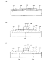
次に、図1(A)に示す半導体膜100を用いた半導体素子の一つである、トランジスタの構成について説明する。図1(B)は、半導体膜100を用いて形成されたトランジスタの断面図の一例である。図1(B)に示すトランジスタは、半導体膜100に、ソースまたはドレインとして機能する一対の不純物領域104、105と、チャネル形成領域106とを有する。そして図1(B)に示すトランジスタは、ゲート絶縁膜107を間に挟んでチャネル形成領域106と重なるように、ゲートとして機能する電極108を有する。
Next, a structure of a transistor which is one of semiconductor elements using the
図1(B)に示すトランジスタでは、空洞103が、チャネル形成領域106、電極108と重なる位置に設けられている。なお本発明において、空洞の位置は、図1(B)に示した構成に限定されない。空洞は、一対の不純物領域104、105のいずれか一方と重なるように形成されていても良いし、一対の不純物領域104、105及びチャネル形成領域106と重なるように形成されていても良い。少なくともチャネル形成領域106と重なるように空洞を形成する場合、不純物領域104、105とのみ重なるように空洞を形成する場合に比べて、よりセルフヒーティングを抑えることが出来る。
In the transistor illustrated in FIG. 1B, the
次に、2つの空洞と重なるように形成される半導体膜110を用いたトランジスタの構成について説明する。図1(C)は、2つの空洞と重なる半導体膜110を用いて形成されたトランジスタの断面図の一例である。図1(C)に示すトランジスタは、半導体膜110に、ソースまたはドレインとして機能する一対の不純物領域111、112と、チャネル形成領域113とを有する。そして図1(C)に示すトランジスタは、ゲート絶縁膜114を間に挟んでチャネル形成領域113と重なるように、ゲートとして機能する電極115を有する。
Next, a structure of a transistor using the
図1(C)に示すトランジスタでは、半導体膜110とベース基板116との間に、絶縁膜117が有する開口部によって形成される空洞118、119を有する。そして空洞118、119が、一対の不純物領域111、112と、それぞれ重なる位置に設けられている。空洞118、119が少なくとも不純物領域111、112と重なっている場合、チャネル形成領域113とのみ重なっている空洞を形成する場合と比べて、トランジスタの接合容量をより低減させることが出来る。
In the transistor illustrated in FIG. 1C,
本発明の半導体装置が有するトランジスタは、半導体膜100、110とベース基板102、116の間に空洞103、118、119を有しており、さらに半導体膜100、110と空洞103、118、119とがそれぞれ接している。よって、例えば酸化珪素などの無機絶縁膜に比べて比誘電率の低い空気、窒素、不活性ガスなどで空洞103、118、119を満たしておくことで、トランジスタの寄生容量または接合容量を低減することが出来る。上記気体は、温度変化に伴う体積膨張を抑えるために、水分の含有率を低減させておくのが望ましい。なお、実際のところ半導体膜100、110の、空洞103、118、119とそれぞれ接する部分には、自然酸化膜が形成される場合がある。しかし特許文献2に記載されている絶縁膜は数μmから数百μmの膜厚を有していることが前提となっており、自然酸化膜は、上記の絶縁膜に比べてその膜厚は数nm程度と飛躍的に薄い。よって本発明は、半導体膜100、110の空洞103、118、119に接する部分に上記膜厚を有する絶縁膜を形成した場合に比べて、トランジスタの寄生容量または接合容量を低減することが出来ると言える。
The transistor included in the semiconductor device of the present invention includes
なお本実施の形態では、空洞103、118、119を気体で満たす場合について示したが、本発明はこの構成に限定されない。例えば空洞103、118、119を、酸化珪素などの無機絶縁膜よりも比誘電率の低い材料、例えば内部に多数の気孔を有する多孔質絶縁膜(ポーラス材料)などで満たすようにしても良い。
Note that although the case where the
なお本発明の範疇に含まれる半導体装置には、マイクロプロセッサ、画像処理回路などの集積回路や、半導体表示装置等、ありとあらゆる半導体装置が含まれる。半導体表示装置には、液晶表示装置、有機発光素子(OLED)に代表される発光素子を各画素に備えた発光装置、DMD(Digital Micromirror Device)、PDP(Plasma Display Panel)、FED(Field Emission Display)等や、半導体膜を用いた回路素子を駆動回路に有しているその他の表示装置がその範疇に含まれる。 Note that semiconductor devices included in the scope of the present invention include all kinds of semiconductor devices such as integrated circuits such as microprocessors and image processing circuits, semiconductor display devices, and the like. The semiconductor display device includes a liquid crystal display device, a light-emitting device including a light-emitting element typified by an organic light-emitting element (OLED) in each pixel, DMD (Digital Micromirror Device), PDP (Plasma Display Panel), FED (Field Emission Display). And other display devices having a circuit element using a semiconductor film in a driver circuit are included in the category.
(実施の形態2)
本実施の形態では、本発明の半導体装置が有するトランジスタの、より具体的な構成について説明する。
(Embodiment 2)
In this embodiment, a more specific structure of the transistor included in the semiconductor device of the present invention will be described.
図2に、本発明の半導体装置が有するトランジスタの、断面図及び上面図の一例を示す。図2(A)はトランジスタの上面図であり、図2(A)のA−A’における断面図を図2(B)に、図2(A)のB−B’における断面図を図2(C)に示す。 FIG. 2 illustrates an example of a cross-sectional view and a top view of a transistor included in a semiconductor device of the present invention. 2A is a top view of the transistor. FIG. 2B is a cross-sectional view taken along line AA ′ in FIG. 2A, and FIG. 2B is a cross-sectional view taken along line BB ′ in FIG. Shown in (C).
図2に示すトランジスタは、活性層として機能する半導体膜120と、半導体膜120と重なる部分がゲートとして機能する電極121と、半導体膜120と電極121の間に設けられたゲート絶縁膜122とを有する。また半導体膜120は、ソースまたはドレインとして機能する不純物領域123、124、チャネル形成領域125、不純物領域123、124とチャネル形成領域125の間に設けられたLDD(Lightly Doped Drain)領域126、127を有している。
The transistor illustrated in FIG. 2 includes a
半導体膜120とベース基板129の間には、絶縁膜131が形成されている。そして、絶縁膜131が有する開口部によって、半導体膜120とベース基板129の間に空洞130が1つ形成されている。図2では、空洞130が、半導体膜120と重なる領域の内部に完全に納まっている。また空洞130は、半導体膜120のうち、チャネル形成領域125と重なっている。少なくともチャネル形成領域125と重なるように空洞を形成する場合、不純物領域123、124とのみ重なるように空洞を形成する場合に比べて、よりセルフヒーティングを抑えることが出来る。
An insulating
なお図2では、空洞130が半導体膜120と重なる領域の内部に完全に納まっているが、本発明はこの構成に限定されない。空洞130が半導体膜120と重なる領域の外部にまで広がっていても良い。この場合、空洞130が半導体膜120と重なる領域の外部において開口していることになる。空洞130が開口していることで、空洞130の内部と外部の気圧の差がなくなる。よって、加熱処理における温度変化が急激であっても半導体膜120の形状が変化するのを防ぐことが出来る。
In FIG. 2, the
なお図2に示すトランジスタは、半導体膜120がLDD領域126、127を有しているが、本発明はこの構成に限定されない。LDD領域126、127は必ずしも設けなくとも良いし、或いはいずれか一方のみが設けられていても良い。また図2に示すトランジスタは、半導体膜120のうち、電極121と重なっている領域とは異なる領域にLDD領域126、127が設けられているが、本発明はこの構成に限定されない。LDD領域126、127は、電極121と重なっている領域に設けられていても良い。或いは、電極121と重なっている領域と、それ以外の領域とに跨るように設けられていても良い。
Note that in the transistor illustrated in FIG. 2, the
また図2に示すトランジスタは、LDD領域126、127を形成する際にマスクとして用いるサイドウォール128が電極121の側部に設けられているが、本発明はこの構成に限定されない。
In the transistor illustrated in FIGS. 2A and 2B, the
図3に、本発明の半導体装置が有するトランジスタの、断面図及び上面図の一例を示す。図3(A)はトランジスタの上面図であり、図3(A)のA−A’における断面図を図3(B)に、図3(A)のB−B’における断面図を図3(C)に示す。 FIG. 3 shows an example of a cross-sectional view and a top view of a transistor included in a semiconductor device of the present invention. 3A is a top view of the transistor. FIG. 3B is a cross-sectional view taken along line AA ′ in FIG. 3A, and FIG. 3B is a cross-sectional view taken along line BB ′ in FIG. Shown in (C).
図3に示すトランジスタは、活性層として機能する半導体膜140と、半導体膜140と重なる部分がゲートとして機能する電極141と、半導体膜140と電極141の間に設けられたゲート絶縁膜142とを有する。また半導体膜140は、ソースまたはドレインとして機能する不純物領域143、144、チャネル形成領域145、不純物領域143、144とチャネル形成領域145の間に設けられたLDD(Lightly Doped Drain)領域146、147を有している。
3 includes a
半導体膜140とベース基板149の間には、絶縁膜152が形成されている。そして、絶縁膜152が有する開口部によって、半導体膜140とベース基板149の間に2つの空洞150と空洞151が形成されている。空洞150は不純物領域143と、空洞151は不純物領域144と重なっている。空洞150、151が少なくとも不純物領域143、144と重なっている場合、チャネル形成領域145とのみ重なっている空洞を形成する場合と比べて、トランジスタの接合容量をより低減させることが出来る。なお、空洞150と空洞151は、半導体膜140と重なる領域の内部に完全に納まっていても良いし、図3のように、空洞150、空洞151が半導体膜140と重なる領域の外部にまで広がっていても良い。後者の場合、空洞150、空洞151が半導体膜140と重なる領域の外部において開口していることになる。空洞150、151が開口している場合、空洞150、151の内部と外部の気圧の差がなくなる。よって、加熱処理における温度変化が急激であっても、半導体膜140の形状が変化するのを防ぐことが出来る。
An insulating
なお図3に示すトランジスタは、半導体膜140がLDD領域146、147を有しているが、本発明はこの構成に限定されない。LDD領域146、147は必ずしも設けなくとも良いし、或いはいずれか一方のみが設けられていても良い。また図3に示すトランジスタは、半導体膜140のうち、電極141と重なっている領域とは異なる領域にLDD領域146、147が設けられているが、本発明はこの構成に限定されない。LDD領域146、147は、電極141と重なっている領域に設けられていても良い。或いは、電極141と重なっている領域と、それ以外の領域とに跨るように設けられていても良い。
Note that in the transistor illustrated in FIG. 3, the
また図3に示すトランジスタは、LDD領域146、147を形成する際にマスクとして用いるサイドウォール148が電極141の側部に設けられているが、本発明はこの構成に限定されない。
In the transistor illustrated in FIGS. 3A and 3B, the
図4に、本発明の半導体装置が有するトランジスタの、断面図及び上面図の一例を示す。図4(A)はトランジスタの上面図であり、図4(A)のA−A’における断面図を図4(B)に、図4(A)のB−B’における断面図を図4(C)に示す。 FIG. 4 illustrates an example of a cross-sectional view and a top view of a transistor included in a semiconductor device of the present invention. 4A is a top view of the transistor. FIG. 4B is a cross-sectional view taken along line AA ′ in FIG. 4A and FIG. 4B is a cross-sectional view taken along line BB ′ in FIG. Shown in (C).
図4に示すトランジスタは、活性層として機能する半導体膜160と、半導体膜160と重なる部分がゲートとして機能する電極161と、半導体膜160と電極161の間に設けられたゲート絶縁膜162とを有する。また半導体膜160は、ソースまたはドレインとして機能する不純物領域163、164、チャネル形成領域165、不純物領域163、164とチャネル形成領域165の間に設けられたLDD(Lightly Doped Drain)領域166、167を有している。
4 includes a
半導体膜160とベース基板169の間には、絶縁膜171が形成されている。そして、絶縁膜171が有する開口部によって、半導体膜160とベース基板169の間に1つの空洞172が形成されている。そして空洞172は不純物領域163、164及びチャネル形成領域165と重なっている。空洞172が不純物領域163、164及びチャネル形成領域165と重なっている場合、セルフヒーティングを抑えるのみならず、トランジスタの接合容量をより低減させることが出来る。なお空洞172は、図4のように、半導体膜160と重なる領域の内部に完全に納まっていても良いし、空洞172が半導体膜160と重なる領域の外部にまで広がっていても良い。後者の場合、空洞172が半導体膜160と重なる領域の外部において開口していることになる。空洞172が開口している場合、空洞172の内部と外部の気圧の差がなくなる。よって、加熱処理における温度変化が急激であっても、半導体膜160の形状が変化するのを防ぐことが出来る。
An insulating
なお図4に示すトランジスタは、半導体膜160がLDD領域166、167を有しているが、本発明はこの構成に限定されない。LDD領域166、167は必ずしも設けなくとも良いし、或いはいずれか一方のみが設けられていても良い。また図4に示すトランジスタは、半導体膜160のうち、電極161と重なっている領域とは異なる領域にLDD領域166、167が設けられているが、本発明はこの構成に限定されない。LDD領域166、167は、電極161と重なっている領域に設けられていても良い。或いは、電極161と重なっている領域と、それ以外の領域とに跨るように設けられていても良い。
Note that in the transistor illustrated in FIGS. 4A and 4B, the
また図4に示すトランジスタは、LDD領域166、167を形成する際にマスクとして用いるサイドウォール168が電極161の側部に設けられているが、本発明はこの構成に限定されない。
In the transistor illustrated in FIGS. 4A and 4B, a
図5に、本発明の半導体装置が有するトランジスタの、断面図及び上面図の一例を示す。図5(A)はトランジスタの上面図であり、図5(A)のA−A’における断面図を図5(B)に、図5(A)のB−B’における断面図を図5(C)、図5(A)のC−C’における断面図を図5(D)に示す。 FIG. 5 illustrates an example of a cross-sectional view and a top view of a transistor included in a semiconductor device of the present invention. 5A is a top view of the transistor. FIG. 5B is a cross-sectional view taken along the line AA ′ in FIG. 5A and FIG. 5B is a cross-sectional view taken along the line BB ′ in FIG. FIG. 5D is a cross-sectional view taken along the line CC ′ of FIG. 5C.
図5に示すトランジスタは、活性層として機能する半導体膜180と、半導体膜180と重なる部分がゲートとして機能する電極181と、半導体膜180と電極181の間に設けられたゲート絶縁膜182とを有する。また半導体膜180は、ソースまたはドレインとして機能する不純物領域183、184、チャネル形成領域185、不純物領域183、184とチャネル形成領域185の間に設けられたLDD(Lightly Doped Drain)領域186、187を有している。
5 includes a
半導体膜180とベース基板189の間には、絶縁膜191が形成されている。そして、絶縁膜191が有する開口部によって、半導体膜180とベース基板189の間に、複数の空洞192〜195が設けられている。空洞192〜195は、不純物領域183、184及びチャネル形成領域185と重なっている。空洞192〜195が不純物領域183、184及びチャネル形成領域185と重なることで、セルフヒーティングを抑えるのみならず、トランジスタの接合容量をより低減させることが出来る。
An insulating
なお、空洞192〜195は、半導体膜180と重なる領域の内部に完全に納まっていても良いし、図5のように、半導体膜180と重なる領域の外部にまで広がっていても良い。後者の場合、空洞192〜195が半導体膜180と重なる領域の外部において開口していることになる。空洞192〜195が開口している場合、空洞192〜195の内部と外部の気圧の差がなくなる。よって、加熱処理における温度変化が急激であっても、半導体膜180の形状が変化するのを防ぐことが出来る。
Note that the
なお図5に示すトランジスタは、半導体膜180がLDD領域186、187を有しているが、本発明はこの構成に限定されない。LDD領域186、187は必ずしも設けなくとも良いし、或いはいずれか一方のみが設けられていても良い。また図5に示すトランジスタは、半導体膜180のうち、電極181と重なっている領域とは異なる領域にLDD領域186、187が設けられているが、本発明はこの構成に限定されない。LDD領域186、187は、電極181と重なっている領域に設けられていても良い。或いは、電極181と重なっている領域と、それ以外の領域とに跨るように設けられていても良い。
Note that in the transistor illustrated in FIG. 5, the
また図5に示すトランジスタは、LDD領域186、187を形成する際にマスクとして用いるサイドウォール188が電極181の側部に設けられているが、本発明はこの構成に限定されない。
In the transistor illustrated in FIGS. 5A and 5B, a
なお、半導体膜の下部に設けられる空洞が図4に示すように単数である場合、半導体膜の下部により広い面積で空洞をレイアウトすることが可能になるので、空洞が複数の場合よりも接合容量及び寄生容量をより低減させることができ、セルフヒーティングもより抑えることができる。また、半導体膜の下部に設けられる空洞が図5に示すように複数である場合、単数の場合よりも物理的強度のより強いトランジスタを形成することが出来る。 Note that when the number of cavities provided in the lower part of the semiconductor film is single as shown in FIG. 4, it is possible to lay out the cavity with a larger area in the lower part of the semiconductor film. In addition, parasitic capacitance can be further reduced, and self-heating can be further suppressed. Further, when there are a plurality of cavities provided in the lower portion of the semiconductor film as shown in FIG. 5, a transistor having a higher physical strength than that of a single cavity can be formed.
また図2に示すトランジスタの場合、チャネル形成領域と重なるように空洞が1つだけ設けられているが、本発明はこの構成に限定されない。チャネル形成領域と重なるように空洞が複数設けられていても良い。空洞が単数である場合、チャネル形成領域の下部により広い面積で空洞をレイアウトすることが可能になるので、空洞が複数の場合よりもセルフヒーティングをより抑えることができる。また、チャネル形成領域の下部に設けられる空洞が複数である場合、単数の場合よりも物理的強度のより強いトランジスタを形成することが出来る。 In the case of the transistor shown in FIG. 2, only one cavity is provided so as to overlap with the channel formation region; however, the present invention is not limited to this structure. A plurality of cavities may be provided so as to overlap with the channel formation region. When the number of the cavities is single, the cavity can be laid out in a wider area below the channel formation region, so that self-heating can be suppressed more than when there are a plurality of cavities. In addition, when there are a plurality of cavities provided in the lower portion of the channel formation region, a transistor having higher physical strength than a single cavity can be formed.
また図3に示すトランジスタの場合、各不純物領域と重なるような空洞が1つずつ設けられているが、本発明はこの構成に限定されない。一つの不純物領域と重なる空洞が複数設けられていても良い。一つの不純物領域と重なる空洞が単数である場合、不純物領域の下部により広い面積で空洞をレイアウトすることが可能になるので、空洞が複数の場合よりもセルフヒーティングをより抑えることができる。また、1つの不純物領域の下部に設けられる空洞が複数である場合、単数の場合よりも物理的強度のより強いトランジスタを形成することが出来る。 In the case of the transistor shown in FIG. 3, one cavity is provided so as to overlap each impurity region, but the present invention is not limited to this structure. A plurality of cavities overlapping with one impurity region may be provided. When a single cavity overlaps with one impurity region, the cavity can be laid out in a wider area below the impurity region, so that self-heating can be suppressed more than when a plurality of cavities are provided. In addition, when there are a plurality of cavities provided below one impurity region, a transistor having a higher physical strength than that of a single cavity can be formed.
本実施の形態は、上記実施の形態と適宜組み合わせて実施することが可能である。 This embodiment can be implemented in combination with any of the above embodiments as appropriate.
(実施の形態3)
本実施の形態では、半導体基板(ボンド基板)から、開口部を有する絶縁膜が形成された支持基板(ベース基板)に半導体膜を転置する、本発明の半導体装置の作製方法について説明する。
(Embodiment 3)
In this embodiment, a method for manufacturing a semiconductor device of the present invention, in which a semiconductor film is transferred from a semiconductor substrate (bond substrate) to a supporting substrate (base substrate) over which an insulating film having an opening is formed, will be described.
まず図6(A)に示すように、ボンド基板200に、矢印で示すように水素又は希ガス、或いは水素イオン又は希ガスイオンを照射し、ボンド基板200の表面から一定の深さの領域に、微小ボイドを有する欠陥層201を形成する。欠陥層201が形成される位置は、上記注入の加速電圧によって決まる。そして欠陥層201の位置により、ボンド基板200からベース基板に転置する半導体膜205の厚さが決まるので、注入の加速電圧は半導体膜の厚さを考慮して行う。当該半導体膜205の厚さは10nm乃至200nm、好ましくは10nm乃至50nmの厚さとする。例えば水素をボンド基板200に注入する場合、ドーズ量は1×10¹⁶乃至1×10¹⁷/cm2とするのが望ましい。
First, as shown in FIG. 6A, the
次に図6(B)に示すように、ベース基板202上に形成された絶縁膜203を所望の形状に加工(パターニング)することで、絶縁膜203を部分的に除去して開口部204を形成する。ベース基板202は開口部204において露出していても良いし、開口部204において絶縁膜203に覆われていても良い。具体的には、レジストで形成されたマスクを用い、絶縁膜203をエッチングすることで、パターニングを行うことが出来る。開口部204は、後にトランジスタの半導体膜とベース基板202の間に形成される空洞に相当する。よって開口部204の形成は、トランジスタの半導体膜のレイアウトを考慮して行われる。
Next, as shown in FIG. 6B, the insulating
絶縁膜203は、酸化珪素、窒化酸化珪素、窒化珪素等の絶縁性を有する材料を用いて形成する。例えば酸化珪素を絶縁膜203として用いる場合、絶縁膜203はシランと酸素、TEOS(テトラエトキシシラン)と酸素等の混合ガスを用い、熱CVD、プラズマCVD、常圧CVD、バイアスECRCVD等の気相成長法によって形成することができる。この場合、絶縁膜203の表面を酸素プラズマ処理で緻密化しても良い。
The insulating
また絶縁膜203として、有機シランガスを用いて化学気相成長法により作製される酸化珪素を用いていても良い。有機シランガスとしては、珪酸エチル(TEOS:化学式Si(OC2H5)4)、テトラメチルシラン(TMS:化学式Si(CH3)4)、テトラメチルシクロテトラシロキサン(TMCTS)、オクタメチルシクロテトラシロキサン(OMCTS)、ヘキサメチルジシラザン(HMDS)、トリエトキシシラン(SiH(OC2H5)3)、トリスジメチルアミノシラン(SiH(N(CH3)2)3)等のシリコン含有化合物を用いることができる。
As the insulating
絶縁膜203は、単数の絶縁膜を用いたものであっても、複数の絶縁膜を積層して用いたものであっても良い。例えば本実施の形態では、ベース基板202に近い側から、窒素よりも酸素の含有量が高い窒化酸化珪素、酸素よりも窒素の含有量が高い窒化酸化珪素、有機シランガスを用いて化学気相成長法により作製される酸化珪素の順に積層された絶縁膜203を用いる。
The insulating
また、窒化珪素を絶縁膜203として用いる場合、シランとアンモニアの混合ガスを用い、プラズマCVD等の気相成長法によって形成することができる。また、窒化酸化珪素を絶縁膜203として用いる場合、シランとアンモニアの混合ガス、またはシランと酸化窒素の混合ガスを用い、プラズマCVD等の気相成長法によって形成することができる。
Further, when silicon nitride is used for the insulating
なお、ボンド基板200と、ベース基板202とを貼り合わせる前に、ボンド基板200に水素化処理を行うようにしても良い。水素化処理は、例えば、水素雰囲気中において350℃、2時間程度行う。
Note that hydrogenation treatment may be performed on the
マスクを除去した後、図6(C)に示すように、ボンド基板200と、ベース基板202とを、絶縁膜203を間に挟むように貼り合わせる。ボンド基板200とベース基板202の貼り合わせは、開口部204がボンド基板200側を向くように行う。絶縁膜203とボンド基板200とが、開口部204以外の領域において接合することで、ボンド基板200とベース基板202とを貼り合わせることができる。
After the mask is removed, as shown in FIG. 6C, the
接合の形成はファン・デル・ワールス力を用いて行われており、室温で強固な接合が形成される。なお、上記接合は低温で行うことが可能であるため、ベース基板202は様々なものを用いることが可能である。例えばベース基板202としては、アルミノシリケートガラス、バリウムホウケイ酸ガラス、アルミノホウケイ酸ガラスなどのガラス基板の他、石英基板、サファイア基板などの基板を用いることが出来る。さらにベース基板202として、シリコン、ガリウムヒ素、インジウムリンなどの半導体基板などを用いることができる。
The bond is formed using van der Waals force, and a strong bond is formed at room temperature. Note that since the bonding can be performed at a low temperature, a variety of
なお、半導体基板をベース基板202として用いる場合、ベース基板202を熱酸化させることで、絶縁膜203を形成することができる。
Note that in the case where a semiconductor substrate is used as the
ボンド基板200として、シリコン、ゲルマニウムなどの単結晶半導体基板または多結晶半導体基板を用いることができる。その他に、ガリウムヒ素、インジウムリンなどの化合物半導体で形成された単結晶半導体基板または多結晶半導体基板を、ボンド基板200として用いることができる。またボンド基板200として、結晶格子に歪みを有するシリコン、シリコンに対しゲルマニウムが添加されたシリコンゲルマニウムなどの半導体基板を用いていても良い。歪みを有するシリコンは、シリコンよりも格子定数の大きいシリコンゲルマニウムまたは窒化珪素上における成膜により、形成することができる。
As the
なおベース基板202とボンド基板200とを貼り合わせた後に、加熱処理又は加圧処理を行っても良い。加熱処理又は加圧処理を行うことで接合強度を向上させることができる。
Note that heat treatment or pressure treatment may be performed after the
ボンド基板200とベース基板202の間で接合を行った後、熱処理を行うことにより、欠陥層201において隣接する微小ボイドどうしが結合して、微小ボイドの体積が増大する。その結果、図6(D)に示すように、欠陥層201においてボンド基板200が劈開し、ボンド基板200の一部であった半導体膜205が乖離する。熱処理の温度はボンド基板200の耐熱温度以下で行うことが好ましく、例えば400℃乃至600℃の範囲内で熱処理を行えば良い。この剥離により、半導体膜205が、ベース基板202に転置される。その後、絶縁膜203と半導体膜205の接合をさらに強固にするため、400℃乃至600℃の熱処理を行うのが好ましい。
After bonding between the
半導体膜205の結晶面方位はボンド基板200の面方位によって制御することができる。形成する半導体素子に適した結晶面方位を有するボンド基板200を、適宜選択して用いればよい。またトランジスタの移動度は半導体膜205の結晶面方位によって異なる。より移動度の高いトランジスタを得たい場合、チャネルの向きと結晶面方位とを考慮し、ボンド基板200の貼り合わせの方向を定めるようにする。
The crystal plane orientation of the
半導体膜205とベース基板202の間には、開口部204によって形成される一対の空洞207が設けられている。
A pair of
次に、図7(A)に示すように、転置された半導体膜205の表面を平坦化する。平坦化は必ずしも必須ではないが、平坦化を行うことで、後に形成されるトランジスタにおいて半導体膜205とゲート絶縁膜の界面の特性を向上させることが出来る。具体的に平坦化は、化学的機械的研磨(CMP:Chemical Mechanical Polishing)または液体ジェット研磨などにより、行うことができる。半導体膜205の厚さは、上記平坦化により薄膜化される。平坦化後の半導体膜205は、5nm乃至25nmの厚さであることが望ましい。
Next, as shown in FIG. 7A, the surface of the transferred
なお本実施の形態では、欠陥層201の形成により半導体膜205をボンド基板200から剥離するスマートカット法を用いる場合について示すが、ELTRAN(Epitaxial Layer Transfer)、誘電体分離法、PACE(Plasma Assisted Chemical Etching)法などの、他の貼り合わせ法を用いて半導体膜205をベース基板202に貼り合わせるようにしても良い。
Note that in this embodiment mode, a smart cut method in which the
次に、図7(B)に示すように、半導体膜205をパターニングすることで、島状の半導体膜206を形成する。半導体膜205をパターニング後においても、島状の半導体膜206とベース基板202の間には、開口部204によって形成される一対の空洞207が維持されている。
Next, as illustrated in FIG. 7B, the
上記工程を経て形成された半導体膜206を用い、本発明はトランジスタ等の各種半導体素子を形成することが出来る。図7(C)には、半導体膜206を用いて形成されたトランジスタ210を例示している。
By using the
本発明の作製方法では、開口部204をエッチングで形成しているので、所望の深さ及び形状を有する空洞207を、簡単な手順で制御良く形成することが出来る。
In the manufacturing method of the present invention, since the
また作製されたトランジスタ210は、半導体膜206とベース基板202の間に空洞207を有しており、さらに半導体膜206と空洞207とが接している。よって、例えば酸化珪素などの無機絶縁膜に比べて比誘電率の低い空気、窒素、不活性ガスなどで空洞207を満たしておくことで、トランジスタ210の寄生容量または接合容量を低減することが出来る。上記気体は、温度変化に伴う体積膨張を抑えるために、水分の含有率を低減させておくのが望ましい。なお実際のところ半導体膜206の、空洞207と接する部分には、自然酸化膜が形成される場合がある。しかし特許文献2に記載されている絶縁膜は数μmから数百μmの膜厚を有していることが前提となっており、自然酸化膜は、上記の絶縁膜に比べてその膜厚は数nm程度と飛躍的に薄い。よって本発明は、半導体膜206の空洞に接する部分に上記膜厚を有する絶縁膜を形成した場合に比べて、トランジスタ210の寄生容量または接合容量を低減することが出来ると言える。
The manufactured
なお本実施の形態では、空洞207を気体で満たす場合について示したが、本発明はこの構成に限定されない。例えば空洞207を、酸化珪素などの無機絶縁膜よりも比誘電率の低い材料、例えば内部に多数の気孔を有する多孔質絶縁膜(ポーラス材料)などで満たすようにしても良い。
Note that although the case where the
また本実施の形態では、島状の半導体膜206とベース基板202の間に空洞207が2つ設けられている構成を示しているが、本発明はこの構成に限定されない。設けられる空洞207は単数であっても良いし、3以上の複数であっても良い。また本実施の形態では、ソースまたはドレインとして機能する不純物領域211と重なるように空洞207が形成されているが、本発明はこの構成に限定されない。半導体膜206のチャネル形成領域212と重なるように空洞207が形成されていても良いし、一対の不純物領域211及びチャネル形成領域212と重なるように空洞207が形成されていても良い。
In this embodiment mode, a structure in which two
なお空洞207が少なくとも不純物領域211と重なっている場合、チャネル形成領域212とのみ重なっている空洞207を形成する場合と比べて、トランジスタ210の接合容量をより低減させることが出来る。また、少なくともチャネル形成領域212と重なっている空洞207を形成する場合、不純物領域211とのみ重なっている空洞207を形成する場合に比べて、よりセルフヒーティングを抑えることが出来る。
Note that in the case where the
本実施の形態は、上記実施の形態と適宜組み合わせて実施することが可能である。 This embodiment can be implemented in combination with any of the above embodiments as appropriate.
(実施の形態4)
本実施の形態では、開口部を有する絶縁膜が形成された半導体基板(ボンド基板)と、支持基板(ベース基板)とを貼り合わせることで、半導体膜をベース基板に転置する、本発明の半導体装置の作製方法について説明する。
(Embodiment 4)
In this embodiment mode, a semiconductor substrate in which an insulating film having an opening is formed (bond substrate) and a supporting substrate (base substrate) are attached to each other so that the semiconductor film is transferred to the base substrate. A method for manufacturing the device will be described.
まず図8(A)に示すように、表面に絶縁膜301が形成されたボンド基板300を用意する。絶縁膜301は、酸化珪素、窒化酸化珪素、窒化珪素等の絶縁性を有する材料を用いて形成する。絶縁膜301の膜厚は後に形成される欠陥層302の深さに関与するため、その膜厚は均一であることが望ましい。例えば酸化珪素を絶縁膜301として用いる場合、絶縁膜301はボンド基板300を熱酸化することで形成するのが望ましく、例えば、水蒸気雰囲気下で900〜1100℃の熱処理により形成すると良い。或いは酸素プラズマ処理によりボンド基板300を酸化することで、絶縁膜301を形成しても良い。また酸化珪素を絶縁膜301として用いる場合、絶縁膜301はシランと酸素、TEOS(テトラエトキシシラン)と酸素等の混合ガスを用い、熱CVD、プラズマCVD、常圧CVD、バイアスECRCVD等の気相成長法によって形成することもできる。この場合、絶縁膜301の表面を酸素プラズマ処理で緻密化しても良い。
First, as shown in FIG. 8A, a
また絶縁膜301として、有機シランガスを用いて化学気相成長法により作製される酸化珪素を用いていても良い。有機シランガスとしては、珪酸エチル(TEOS:化学式Si(OC2H5)4)、テトラメチルシラン(TMS:化学式Si(CH3)4)、テトラメチルシクロテトラシロキサン(TMCTS)、オクタメチルシクロテトラシロキサン(OMCTS)、ヘキサメチルジシラザン(HMDS)、トリエトキシシラン(SiH(OC2H5)3)、トリスジメチルアミノシラン(SiH(N(CH3)2)3)等のシリコン含有化合物を用いることができる。
As the insulating
絶縁膜301は、単数の絶縁膜を用いたものであっても、複数の絶縁膜を積層して用いたものであっても良い。例えば本実施の形態では、ボンド基板300に近い側から、窒素よりも酸素の含有量が高い窒化酸化珪素、酸素よりも窒素の含有量が高い窒化酸化珪素、有機シランガスを用いて化学気相成長法により作製される酸化珪素の順に積層された絶縁膜301を用いる。
The insulating
また、窒化珪素を絶縁膜301として用いる場合、シランとアンモニアの混合ガスを用い、プラズマCVD等の気相成長法によって形成することができる。また、窒化酸化珪素を絶縁膜301として用いる場合、シランとアンモニアの混合ガス、またはシランと酸化窒素の混合ガスを用い、プラズマCVD等の気相成長法によって形成することができる。
In the case where silicon nitride is used for the insulating
なお、ボンド基板300から半導体膜305を取り出す工程において、ボンド基板300に高い濃度の水素又は希ガス、或いは水素イオン又は希ガスイオンを注入するので、ボンド基板300の表面が粗くなってしまい、ベース基板との接合で十分な結合強度が得られない場合がある。絶縁膜301を設けることで、水素又は希ガス、或いは水素と希ガスのイオンを注入する際にボンド基板300の表面が保護され、ベース基板とボンド基板300の接合を良好に行うことが出来る。
Note that in the step of removing the
次に、ボンド基板300に、矢印で示すように水素又は希ガス、或いは水素イオン又は希ガスイオンを注入し、ボンド基板300の表面から一定の深さの領域に、微小ボイドを有する欠陥層302を形成する。欠陥層302が形成される位置は、上記注入の加速電圧によって決まる。そして欠陥層302の位置により、ボンド基板300からベース基板に転置する半導体膜305の厚さが決まるので、注入の加速電圧は半導体膜の厚さを考慮して行う。当該半導体膜305の厚さは10nm乃至200nm、好ましくは10nm乃至50nmの厚さとする。例えば水素をボンド基板300に注入する場合、ドーズ量は1×10¹⁶乃至1×10¹⁷/cm2とするのが望ましい。
Next, hydrogen or a rare gas, or hydrogen ions or a rare gas ion is implanted into the
なお本実施の形態では、絶縁膜301をボンド基板300上に形成してからボンド基板300に欠陥層302を形成しているが、本発明はこの構成に限定されない。絶縁膜301を形成する前にボンド基板300に欠陥層302を形成しても良い。或いは、複数の絶縁膜を絶縁膜301として用いる場合、該複数の絶縁膜のうちの幾つかをボンド基板300上に形成した後に、ボンド基板300に欠陥層302を形成し、次に、該複数の絶縁膜のうちの残りの絶縁膜を形成するようにしても良い。この場合、例えば窒化酸化珪素膜と酸化珪素膜を積層したものを、絶縁膜301として用いると良い。そして、窒化酸化珪素膜をボンド基板300上に形成してからボンド基板300に欠陥層302を形成し、次に有機シランガスを用いて化学気相成長法により作製される酸化珪素膜を形成すると良い。
Note that in this embodiment mode, the
次に図8(B)に示すように、ボンド基板300上に形成された絶縁膜301を所望の形状に加工(パターニング)することで、絶縁膜301を部分的に除去して開口部303を形成する。ボンド基板300は開口部303において露出していても良いし、開口部303において絶縁膜301に覆われていても良い。具体的には、レジストで形成されたマスクを用い、絶縁膜301をエッチングすることで、パターニングを行うことが出来る。開口部303は、後にトランジスタの半導体膜とベース基板304の間に形成される空洞に相当する。よって開口部303の形成は、トランジスタの半導体膜のレイアウトを考慮して行われる。
Next, as shown in FIG. 8B, the insulating
なお、ボンド基板300と、ベース基板304とを貼り合わせる前に、ボンド基板300に水素化処理を行うようにしても良い。水素化処理は、例えば、水素雰囲気中において350℃、2時間程度行う。
Note that hydrogenation treatment may be performed on the
マスクを除去した後、図8(C)に示すように、ボンド基板300と、ベース基板304とを、絶縁膜301を間に挟むように貼り合わせる。ボンド基板300とベース基板304の貼り合わせは、開口部303がベース基板304側を向くように行う。絶縁膜301とベース基板304とが、開口部303以外の領域において接合することで、ボンド基板300とベース基板304とを貼り合わせることができる。
After the mask is removed, as shown in FIG. 8C, the
接合の形成はファン・デル・ワールス力を用いて行われており、室温で強固な接合が形成される。なお、上記接合は低温で行うことが可能であるため、ベース基板304は様々なものを用いることが可能である。例えばベース基板304としては、アルミノシリケートガラス、バリウムホウケイ酸ガラス、アルミノホウケイ酸ガラスなどのガラス基板の他、石英基板、サファイア基板などの基板を用いることが出来る。さらにベース基板304として、シリコン、ガリウムヒ素、インジウムリンなどの半導体基板などを用いることができる。
The bond is formed using van der Waals force, and a strong bond is formed at room temperature. Note that since the bonding can be performed at a low temperature, a variety of
ボンド基板300として、シリコン、ゲルマニウムなどの単結晶半導体基板または多結晶半導体基板を用いることができる。その他に、ガリウムヒ素、インジウムリンなどの化合物半導体で形成された単結晶半導体基板または多結晶半導体基板を、ボンド基板300として用いることができる。またボンド基板300として、結晶格子に歪みを有するシリコン、シリコンに対しゲルマニウムが添加されたシリコンゲルマニウムなどの半導体基板を用いていても良い。歪みを有するシリコンは、シリコンよりも格子定数の大きいシリコンゲルマニウムまたは窒化珪素上における成膜により、形成することができる。
As the
なおベース基板304とボンド基板300とを貼り合わせた後に、加熱処理又は加圧処理を行っても良い。加熱処理又は加圧処理を行うことで接合強度を向上させることができる。
Note that heat treatment or pressure treatment may be performed after the
ボンド基板300とベース基板304の間で接合を行った後、熱処理を行うことにより、欠陥層302において隣接する微小ボイドどうしが結合して、微小ボイドの体積が増大する。その結果、図8(D)に示すように、欠陥層302においてボンド基板300が劈開し、ボンド基板300の一部であった半導体膜305と、絶縁膜301とが乖離する。熱処理の温度はボンド基板300の耐熱温度以下で行うことが好ましく、例えば400℃乃至600℃の範囲内で熱処理を行えば良い。この剥離により、半導体膜305と、絶縁膜301とが、ベース基板304に転置される。その後、絶縁膜301とベース基板304の接合をさらに強固にするため、400℃乃至600℃の熱処理を行うのが好ましい。
After bonding between the
半導体膜305の結晶面方位はボンド基板300の面方位によって制御することができる。形成する半導体素子に適した結晶面方位を有するボンド基板300を、適宜選択して用いればよい。またトランジスタの移動度は半導体膜305の結晶面方位によって異なる。より移動度の高いトランジスタを得たい場合、チャネルの向きと結晶面方位とを考慮し、ボンド基板300の貼り合わせの方向を定めるようにする。
The crystal plane orientation of the
半導体膜305とベース基板304の間には、開口部303によって形成される空洞306が設けられている。
A
図8(D)の工程まで終了したら、後は実施の形態3と同様に、転置された半導体膜305の表面を平坦化し、パターニングすることで、島状の半導体膜を形成する。半導体膜305のパターニング後においても、島状の半導体膜とベース基板304の間には、開口部303によって形成される空洞306が維持される。
When the process up to FIG. 8D is completed, the surface of the transferred
上記工程を経て形成された島状の半導体膜を用い、本発明はトランジスタ等の各種半導体素子を形成することが出来る。 By using the island-shaped semiconductor film formed through the above steps, the present invention can form various semiconductor elements such as transistors.
本発明の作製方法では、開口部303をエッチングで形成しているので、所望の深さ及び形状を有する空洞306を、簡単な手順で制御良く形成することが出来る。
In the manufacturing method of the present invention, since the
なお本実施の形態では、欠陥層302の形成により半導体膜305をボンド基板300から剥離するスマートカット法を用いる場合について示すが、ELTRAN(Epitaxial Layer Transfer)、誘電体分離法、PACE(Plasma Assisted Chemical Etching)法などの、他の貼り合わせ法を用いて半導体膜305をベース基板304に貼り合わせるようにしても良い。
Note that in this embodiment mode, a smart cut method in which the
また島状の半導体膜を用いて作製されるトランジスタは、島状の半導体膜とベース基板304の間に空洞306を有しており、さらに半導体膜305と空洞306とが接している。よって、例えば酸化珪素などの無機絶縁膜に比べて比誘電率の低い空気、窒素、不活性ガスなどで空洞306を満たしておくことで、トランジスタの寄生容量または接合容量を低減することが出来る。上記気体は、温度変化に伴う体積膨張を抑えるために、水分の含有率を低減させておくのが望ましい。
In addition, a transistor manufactured using an island-shaped semiconductor film includes a
なお、実際のところ島状の半導体膜の、空洞306と接する部分には、自然酸化膜が形成される場合がある。しかし特許文献2に記載されている絶縁膜は数μmから数百μmの膜厚を有していることが前提となっており、自然酸化膜は、上記の絶縁膜に比べてその膜厚は数nm程度と飛躍的に薄い。よって本発明は、島状の半導体膜の空洞に接する部分に上記膜厚を有する絶縁膜を形成した場合に比べて、トランジスタの寄生容量または接合容量を低減する、或いはセルフヒーティングを抑えることが出来ると言える。
Actually, a natural oxide film may be formed in a portion of the island-shaped semiconductor film in contact with the
なお本実施の形態では、空洞306を気体で満たす場合について示したが、本発明はこの構成に限定されない。例えば空洞306を、酸化珪素などの無機絶縁膜よりも比誘電率の低い材料、例えば内部に多数の気孔を有する多孔質絶縁膜(ポーラス材料)などで満たすようにしても良い。
Note that although the case where the
また本実施の形態では、半導体膜305と接するように絶縁膜301を先に形成してから、絶縁膜301とベース基板304とを接合させている。よって、半導体膜305と絶縁膜301の界面における界面準位密度を、半導体膜305と絶縁膜301とを接合させた場合に比べて、均一にすることができる。従って、半導体膜305をパターニングすることで形成される島状の半導体膜を用いたトランジスタは、閾値電圧などの特性のばらつきをより抑えることができる。
In this embodiment, the insulating
本実施の形態は、上記実施の形態と適宜組み合わせて実施することが可能である。 This embodiment can be implemented in combination with any of the above embodiments as appropriate.
(実施の形態5)
本実施の形態では、開口部を有する絶縁膜が形成された半導体基板(ボンド基板)と、開口部を有する絶縁膜が形成された支持基板(ベース基板)とを貼り合わせることで、半導体膜をベース基板に転置する、本発明の半導体装置の作製方法について説明する。
(Embodiment 5)
In this embodiment, a semiconductor substrate is bonded to a semiconductor substrate (bond substrate) on which an insulating film having an opening is formed and a supporting substrate (base substrate) on which an insulating film having an opening is formed. A method for manufacturing a semiconductor device of the present invention which is transferred to a base substrate will be described.
まず図9(A)に示すように、表面に絶縁膜311が形成されたボンド基板310を用意する。絶縁膜311は、酸化珪素、窒化酸化珪素、窒化珪素等の絶縁性を有する材料を用いて形成する。絶縁膜311の膜厚は後に形成される欠陥層312の深さに関与するため、その膜厚は均一であることが望ましい。例えば酸化珪素を絶縁膜311として用いる場合、絶縁膜311はボンド基板310を熱酸化することで形成するのが望ましく、例えば、水蒸気雰囲気下で900〜1100℃の熱処理により形成すると良い。或いは酸素プラズマ処理によりボンド基板310を酸化することで、絶縁膜311を形成しても良い。また酸化珪素を絶縁膜311として用いる場合、絶縁膜311はシランと酸素、TEOS(テトラエトキシシラン)と酸素等の混合ガスを用い、熱CVD、プラズマCVD、常圧CVD、バイアスECRCVD等の気相成長法によって形成することもできる。この場合、絶縁膜311の表面を酸素プラズマ処理で緻密化しても良い。
First, as shown in FIG. 9A, a
また絶縁膜311として、有機シランガスを用いて化学気相成長法により作製される酸化珪素を用いていても良い。有機シランガスとしては、珪酸エチル(TEOS:化学式Si(OC2H5)4)、テトラメチルシラン(TMS:化学式Si(CH3)4)、テトラメチルシクロテトラシロキサン(TMCTS)、オクタメチルシクロテトラシロキサン(OMCTS)、ヘキサメチルジシラザン(HMDS)、トリエトキシシラン(SiH(OC2H5)3)、トリスジメチルアミノシラン(SiH(N(CH3)2)3)等のシリコン含有化合物を用いることができる。
As the insulating
絶縁膜311は、単数の絶縁膜を用いたものであっても、複数の絶縁膜を積層して用いたものであっても良い。例えば本実施の形態では、ボンド基板310に近い側から、窒素よりも酸素の含有量が高い窒化酸化珪素、酸素よりも窒素の含有量が高い窒化酸化珪素、有機シランガスを用いて化学気相成長法により作製される酸化珪素の順に積層された絶縁膜311を用いる。
The insulating
また、窒化珪素を絶縁膜311として用いる場合、シランとアンモニアの混合ガスを用い、プラズマCVD等の気相成長法によって形成することができる。また、窒化酸化珪素を絶縁膜311として用いる場合、シランとアンモニアの混合ガス、またはシランと酸化窒素の混合ガスを用い、プラズマCVD等の気相成長法によって形成することができる。
In the case where silicon nitride is used for the insulating
なお、ボンド基板310から半導体膜317を取り出す工程において、ボンド基板310に高い濃度の水素又は希ガス、或いは水素イオン又は希ガスイオンを注入するので、ボンド基板310の表面が粗くなってしまい、ベース基板との接合で十分な結合強度が得られない場合がある。絶縁膜311を設けることで、水素又は希ガス、或いは水素と希ガスのイオンを注入する際にボンド基板310の表面が保護され、ベース基板とボンド基板310の接合を良好に行うことが出来る。
Note that in the step of taking out the
次に、ボンド基板310に、矢印で示すように水素又は希ガス、或いは水素イオン又は希ガスイオンを注入し、ボンド基板310の表面から一定の深さの領域に、微小ボイドを有する欠陥層312を形成する。欠陥層312が形成される位置は、上記注入の加速電圧によって決まる。そして欠陥層312の位置により、ボンド基板310からベース基板に転置する半導体膜317の厚さが決まるので、注入の加速電圧は半導体膜の厚さを考慮して行う。当該半導体膜317の厚さは10nm乃至200nm、好ましくは10nm乃至50nmの厚さとする。例えば水素をボンド基板310に注入する場合、ドーズ量は1×10¹⁶乃至1×10¹⁷/cm2とするのが望ましい。
Next, hydrogen or a rare gas, or hydrogen ions or a rare gas ion is implanted into the
なお本実施の形態では、絶縁膜311をボンド基板310上に形成してからボンド基板310に欠陥層312を形成しているが、本発明はこの構成に限定されない。絶縁膜311を形成する前にボンド基板310に欠陥層312を形成しても良い。或いは、複数の絶縁膜を絶縁膜311として用いる場合、該複数の絶縁膜のうちの幾つかをボンド基板310上に形成した後に、ボンド基板310に欠陥層312を形成し、次に、該複数の絶縁膜のうちの残りの絶縁膜を形成するようにしても良い。この場合、例えば窒化酸化珪素膜と酸化珪素膜を積層したものを、絶縁膜311として用いると良い。そして、窒化酸化珪素膜をボンド基板310上に形成してからボンド基板310に欠陥層312を形成し、次に有機シランガスを用いて化学気相成長法により作製される酸化珪素膜を形成すると良い。
Note that in this embodiment mode, the insulating
次に図9(B)に示すように、ボンド基板310上に形成された絶縁膜311を所望の形状に加工(パターニング)することで、絶縁膜311を部分的に除去して開口部313を形成する。ボンド基板310は開口部313において露出していても良いし、開口部313において絶縁膜311に覆われていても良い。具体的には、レジストで形成されたマスクを用い、絶縁膜311をエッチングすることで、パターニングを行うことが出来る。開口部313は、後にトランジスタの半導体膜とベース基板314の間に形成される空洞に相当する。よって開口部313の形成は、トランジスタの半導体膜のレイアウトを考慮して行われる。
Next, as shown in FIG. 9B, the insulating
なお、ボンド基板310と、ベース基板314とを貼り合わせる前に、ボンド基板310に水素化処理を行うようにしても良い。水素化処理は、例えば、水素雰囲気中において350℃、2時間程度行う。
Note that hydrogenation treatment may be performed on the
マスクを除去した後、図9(C)に示すように、ボンド基板310と、ベース基板314とを貼り合わせる。本実施の形態では、開口部315を有する絶縁膜316が形成されたベース基板314を用意する。絶縁膜316は、絶縁膜311として用いることができる上述の材料で、形成することができる。また開口部315はエッチングなどにより形成することができる。ボンド基板310とベース基板314の貼り合わせは、絶縁膜311及び絶縁膜316を間に挟むように、なおかつ開口部313と開口部315とが少なくとも一部重なるように貼り合わせる。絶縁膜311と絶縁膜316とが、開口部313及び開口部315以外の領域において接合することで、ボンド基板310とベース基板314とを貼り合わせることができる。
After the mask is removed, the
接合の形成はファン・デル・ワールス力を用いて行われており、室温で強固な接合が形成される。なお、上記接合は低温で行うことが可能であるため、ベース基板314は様々なものを用いることが可能である。例えばベース基板314としては、アルミノシリケートガラス、バリウムホウケイ酸ガラス、アルミノホウケイ酸ガラスなどのガラス基板の他、石英基板、サファイア基板などの基板を用いることが出来る。さらにベース基板314として、シリコン、ガリウムヒ素、インジウムリンなどの半導体基板などを用いることができる。
The bond is formed using van der Waals force, and a strong bond is formed at room temperature. Note that since the bonding can be performed at a low temperature, a variety of base substrates can be used. For example, as the
なお、半導体基板をベース基板314として用いる場合、ベース基板314を熱酸化させることで、絶縁膜316を形成することができる。
Note that in the case where a semiconductor substrate is used as the
ボンド基板310として、シリコン、ゲルマニウムなどの単結晶半導体基板または多結晶半導体基板を用いることができる。その他に、ガリウムヒ素、インジウムリンなどの化合物半導体で形成された単結晶半導体基板または多結晶半導体基板を、ボンド基板310として用いることができる。またボンド基板310として、結晶格子に歪みを有するシリコン、シリコンに対しゲルマニウムが添加されたシリコンゲルマニウムなどの半導体基板を用いていても良い。歪みを有するシリコンは、シリコンよりも格子定数の大きいシリコンゲルマニウムまたは窒化珪素上における成膜により、形成することができる。
As the
なおベース基板314とボンド基板310とを貼り合わせた後に、加熱処理又は加圧処理を行っても良い。加熱処理又は加圧処理を行うことで接合強度を向上させることができる。
Note that heat treatment or pressure treatment may be performed after the
ボンド基板310とベース基板314の間で接合を行った後、熱処理を行うことにより、欠陥層312において隣接する微小ボイドどうしが結合して、微小ボイドの体積が増大する。その結果、図9(D)に示すように、欠陥層312においてボンド基板310が劈開し、ボンド基板310の一部であった半導体膜317と、絶縁膜311とが乖離する。熱処理の温度はボンド基板310の耐熱温度以下で行うことが好ましく、例えば400℃乃至600℃の範囲内で熱処理を行えば良い。この剥離により、半導体膜317と、絶縁膜311とが、ベース基板314に転置される。その後、絶縁膜311と絶縁膜316の接合をさらに強固にするため、400℃乃至600℃の熱処理を行うのが好ましい。
When bonding is performed between the
半導体膜317の結晶面方位はボンド基板310の面方位によって制御することができる。形成する半導体素子に適した結晶面方位を有するボンド基板310を、適宜選択して用いればよい。またトランジスタの移動度は半導体膜317の結晶面方位によって異なる。より移動度の高いトランジスタを得たい場合、チャネルの向きと結晶面方位とを考慮し、ボンド基板310の貼り合わせの方向を定めるようにする。
The crystal plane orientation of the
半導体膜317とベース基板314の間には、開口部313及び開口部315によって形成される空洞318が設けられている。
A
図9(D)の工程まで終了したら、後は実施の形態3と同様に、転置された半導体膜317の表面を平坦化し、パターニングすることで、島状の半導体膜を形成する。半導体膜317のパターニング後においても、島状の半導体膜とベース基板314の間には、開口部313、315によって形成される空洞318が維持される。
When the process up to the step of FIG. 9D is completed, the surface of the transferred
上記工程を経て形成された島状の半導体膜を用い、本発明はトランジスタ等の各種半導体素子を形成することが出来る。 By using the island-shaped semiconductor film formed through the above steps, the present invention can form various semiconductor elements such as transistors.
本発明の作製方法では、開口部313または開口部315をエッチングで形成しているので、所望の深さ及び形状を有する空洞318を、簡単な手順で制御良く形成することが出来る。
In the manufacturing method of the present invention, since the
なお本実施の形態では、欠陥層312の形成により半導体膜317をボンド基板310から剥離するスマートカット法を用いる場合について示すが、ELTRAN(Epitaxial Layer Transfer)、誘電体分離法、PACE(Plasma Assisted Chemical Etching)法などの、他の貼り合わせ法を用いて半導体膜317をベース基板314に貼り合わせるようにしても良い。
Note that although a smart cut method in which the
また島状の半導体膜を用いて作製されるトランジスタは、島状の半導体膜とベース基板314の間に空洞318を有しており、さらに半導体膜317と空洞318とが接している。よって、例えば酸化珪素などの無機絶縁膜に比べて比誘電率の低い空気、窒素、不活性ガスなどで空洞318を満たしておくことで、トランジスタの寄生容量または接合容量を低減することが出来る。上記気体は、温度変化に伴う体積膨張を抑えるために、水分の含有率を低減させておくのが望ましい。
In addition, a transistor manufactured using an island-shaped semiconductor film includes a
なお、実際のところ島状の半導体膜の、空洞318と接する部分には、自然酸化膜が形成される場合がある。しかし特許文献2に記載されている絶縁膜は数μmから数百μmの膜厚を有していることが前提となっており、自然酸化膜は、上記の絶縁膜に比べてその膜厚は数nm程度と飛躍的に薄い。よって本発明は、島状の半導体膜の空洞に接する部分に上記膜厚を有する絶縁膜を形成した場合に比べて、トランジスタの寄生容量または接合容量を低減する、或いはセルフヒーティングを抑えることが出来ると言える。
Note that a natural oxide film may be actually formed in a portion of the island-shaped semiconductor film in contact with the
なお本実施の形態では、空洞318を気体で満たす場合について示したが、本発明はこの構成に限定されない。例えば空洞318を、酸化珪素などの無機絶縁膜よりも比誘電率の低い材料、例えば内部に多数の気孔を有する多孔質絶縁膜(ポーラス材料)などで満たすようにしても良い。
Note that although the case where the
また本実施の形態では、半導体膜317と接するように絶縁膜311を先に形成してから、絶縁膜311と、ベース基板314上に形成された絶縁膜316とを接合させている。よって、半導体膜317と絶縁膜311の界面における界面準位密度を、半導体膜317と絶縁膜311とを接合させた場合に比べて、均一にすることができる。従って、半導体膜317をパターニングすることで形成される島状の半導体膜を用いたトランジスタは、閾値電圧などの特性のばらつきをより抑えることができる。
In this embodiment, the insulating
本実施の形態は、上記実施の形態と適宜組み合わせて実施することが可能である。 This embodiment can be implemented in combination with any of the above embodiments as appropriate.
(実施の形態6)
本実施の形態では、実施の形態3に示す作製方法を用いて形成された半導体膜で、トランジスタを作製する方法の一例について説明する。なお、実施の形態4または実施の形態5に示す作製方法を用いて形成された半導体膜でも、本実施の形態に示す作製方法でトランジスタを作製することは可能である。
(Embodiment 6)
In this embodiment, an example of a method for manufacturing a transistor with a semiconductor film formed using the manufacturing method described in Embodiment 3 will be described. Note that even with a semiconductor film formed using the manufacturing method described in Embodiment 4 or 5, a transistor can be manufactured by the manufacturing method described in this embodiment.
まず図10(A)に示すように、開口部を有する絶縁膜402を、ベース基板401との間に有する島状の半導体膜403、島状の半導体膜404を形成する。実施の形態3に示す作製方法を用いる場合、絶縁膜402と島状の半導体膜403及び島状の半導体膜404とが接合することで、ベース基板401に島状の半導体膜403及び島状の半導体膜404が貼り合わされている。そして絶縁膜402が有する開口部により、ベース基板401と島状の半導体膜403の間に空洞405が、ベース基板401と島状の半導体膜404の間に空洞406がそれぞれ形成されている。
First, as illustrated in FIG. 10A, an island-shaped
島状の半導体膜403、404には、閾値電圧を制御するために不純物が添加されていても良い。例えば、p型不純物としてボロンを添加する場合、5×1017cm−3以上1×1018cm−3以下の濃度で添加すれば良い。閾値電圧を制御するための不純物の添加は、ベース基板401に半導体膜を転置する前に行っても良いし、転置後に行っても良い。
An impurity may be added to the island-shaped
また島状の半導体膜403、404を形成した後、ゲート絶縁膜407を形成する前に水素化処理を行っても良い。水素化処理は、例えば、水素雰囲気中において350℃、2時間程度行う。
Alternatively, hydrogen treatment may be performed after the island-shaped
次に図10(B)に示すように、島状の半導体膜403、404を覆うように、ゲート絶縁膜407を形成する。ゲート絶縁膜407は、高密度プラズマ処理を行うことにより島状の半導体膜403、404の表面を酸化または窒化することで形成することができる。高密度プラズマ処理は、例えばHe、Ar、Kr、Xeなどの希ガスと酸素、酸化窒素、アンモニア、窒素、水素などの混合ガスとを用いて行う。この場合プラズマの励起をマイクロ波の導入により行うことで、低電子温度で高密度のプラズマを生成することができる。このような高密度のプラズマで生成された酸素ラジカル(OHラジカルを含む場合もある)や窒素ラジカル(NHラジカルを含む場合もある)によって、半導体膜の表面を酸化または窒化することにより、1〜20nm、望ましくは5〜10nmの絶縁膜が半導体膜に接するように形成される。この5〜10nmの絶縁膜をゲート絶縁膜407として用いる。
Next, as illustrated in FIG. 10B, a
上述した高密度プラズマ処理による半導体膜の酸化または窒化は固相反応で進むため、ゲート絶縁膜407と島状の半導体膜403、404の界面準位密度をきわめて低くすることができる。また高密度プラズマ処理により半導体膜を直接酸化または窒化することで、形成される絶縁膜の厚さのばらつきを抑えることが出来る。また半導体膜が結晶性を有する場合、高密度プラズマ処理を用いて半導体膜の表面を固相反応で酸化させることにより、結晶粒界においてのみ酸化が速く進んでしまうのを抑え、均一性が良く、界面準位密度の低いゲート絶縁膜を形成することができる。高密度プラズマ処理により形成された絶縁膜を、ゲート絶縁膜の一部または全部に含んで形成されるトランジスタは、特性のばらつきを抑えることができる。
Since the oxidation or nitridation of the semiconductor film by the high-density plasma treatment described above proceeds by a solid phase reaction, the interface state density between the
或いは、プラズマCVD法またはスパッタリング法などを用い、酸化珪素、酸化窒化珪素、窒化珪素、酸化ハフニウム、酸化アルミニウムまたは酸化タンタルを含む膜を、単層で、または積層させることで、ゲート絶縁膜407を形成しても良い。
Alternatively, by using a plasma CVD method, a sputtering method, or the like, the
次に図10(C)に示すように、ゲート絶縁膜407上に導電膜を形成した後、該導電膜を所定の形状に加工(パターニング)することで、島状の半導体膜403、404の上方に電極408を形成する。導電膜の形成にはCVD法、スパッタリング法等を用いることが出来る。導電膜は、タンタル(Ta)、タングステン(W)、チタン(Ti)、モリブデン(Mo)、アルミニウム(Al)、銅(Cu)、クロム(Cr)、ニオブ(Nb)等を用いることが出来る。また上記金属を主成分とする合金を用いても良いし、上記金属を含む化合物を用いても良い。または、半導体膜に導電性を付与するリン等の不純物元素をドーピングした、多結晶珪素などの半導体を用いて形成しても良い。
Next, as illustrated in FIG. 10C, after forming a conductive film over the
2つの導電膜の組み合わせとして、1層目に窒化タンタルまたはタンタル(Ta)を、2層目にタングステン(W)を用いることが出来る。上記例の他に、窒化タングステンとタングステン、窒化モリブデンとモリブデン、アルミニウムとタンタル、アルミニウムとチタン等が挙げられる。タングステンや窒化タンタルは、耐熱性が高いため、2層の導電膜を形成した後の工程において、熱活性化を目的とした加熱処理を行うことができる。また、2層目の導電膜の組み合わせとして、例えば、n型を付与する不純物がドーピングされた珪素とNiSi(ニッケルシリサイド)、n型を付与する不純物がドーピングされたSiとWSix等も用いることが出来る。 As a combination of two conductive films, tantalum nitride or tantalum (Ta) can be used for the first layer, and tungsten (W) can be used for the second layer. In addition to the above examples, tungsten nitride and tungsten, molybdenum nitride and molybdenum, aluminum and tantalum, aluminum and titanium, and the like can be given. Since tungsten and tantalum nitride have high heat resistance, heat treatment for thermal activation can be performed in the step after forming the two-layer conductive film. As a combination of the second conductive film, for example, silicon and NiSi (nickel silicide) doped with an impurity imparting n-type, Si and WSix doped with an impurity imparting n-type, and the like may be used. I can do it.
また、本実施の形態では電極408を単層の導電膜で形成しているが、本実施の形態はこの構成に限定されない。電極408は積層された複数の導電膜で形成されていても良い。3つ以上の導電膜を積層する3層構造の場合は、モリブデン膜とアルミニウム膜とモリブデン膜の積層構造を採用するとよい。
In this embodiment mode, the
なお電極408を形成する際に用いるマスクとして、レジストの代わりに酸化珪素、酸化窒化珪素等をマスクとして用いてもよい。この場合、パターニングして酸化珪素、酸化窒化珪素等のマスクを形成する工程が加わるが、エッチング時におけるマスクの膜減りがレジストよりも少ないため、所望の幅を有する電極408を形成することができる。またマスクを用いずに、液滴吐出法を用いて選択的に電極408を形成しても良い。
Note that as a mask used for forming the
なお液滴吐出法とは、所定の組成物を含む液滴を細孔から吐出または噴出することで所定のパターンを形成する方法を意味し、インクジェット法などがその範疇に含まれる。 The droplet discharge method means a method of forming a predetermined pattern by discharging or ejecting droplets containing a predetermined composition from the pores, and includes an ink jet method and the like in its category.
また電極408は、導電膜を形成後、ICP(Inductively Coupled Plasma:誘導結合型プラズマ)エッチング法を用い、エッチング条件(コイル型の電極層に印加される電力量、基板側の電極層に印加される電力量、基板側の電極温度等)を適宜調節することにより、所望のテーパー形状を有するようにエッチングすることができる。また、テーパー形状は、マスクの形状によっても角度等を制御することができる。なお、エッチング用ガスとしては、Cl2、BCl3、SiCl4もしくはCCl4などの塩素系ガス、CF4、SF6もしくはNF3などのフッ素系ガス又は酸素を適宜用いることができる。
In addition, the
ゲート絶縁膜407に高誘電率物質(high−k材料)を用いる場合には、電極408を多結晶シリコン、シリサイド、金属若しくは金属窒化物で形成する。特に高誘電率物質を用いる場合、金属若しくは金属窒化物で電極408を形成することが最も望ましい。例えば、ゲート絶縁膜407と接する導電膜を金属窒化物材料で形成し、その上の導電膜を金属材料で形成する。この組み合わせを用いることによって、ゲート絶縁膜407が薄膜化した場合でも電極408に空乏層が広がってしまうことを防止でき、微細化した場合にもトランジスタの駆動能力を損なうことを防止できる。
In the case where a high dielectric constant material (high-k material) is used for the
次に図10(D)に示すように、電極408をマスクとして一導電型を付与する不純物元素を半導体膜403、404に添加する。本実施の形態では、半導体膜404にp型を付与する不純物元素(例えばボロン)を、半導体膜403にn型を付与する不純物元素(例えばリンまたはヒ素)を添加する。なお、p型を付与する不純物元素を半導体膜404に添加する際、n型の不純物が添加される半導体膜403はマスク等で覆い、p型を付与する不純物元素の添加が選択的に行われるようにする。また、n型を付与する不純物元素を半導体膜403に添加する際、p型の不純物が添加される半導体膜404はマスク等で覆い、n型を付与する不純物元素の添加が選択的に行われるようにする。或いは、先に半導体膜403及び半導体膜404にp型もしくはn型を付与する不純物元素を添加した後、一方の半導体膜のみに選択的により高い濃度でp型もしくはn型を付与する不純物元素のいずれか一方を添加するようにしても良い。上記不純物の添加により、半導体膜403に不純物領域410、半導体膜404に不純物領域411が形成される。
Next, as illustrated in FIG. 10D, an impurity element imparting one conductivity type is added to the
次に、図11(A)に示すように、電極408の側面にサイドウォール412を形成する。サイドウォール412は、例えば、ゲート絶縁膜407及び電極408を覆うように新たに絶縁膜を形成し、垂直方向を主体とした異方性エッチングにより、新たに形成された該絶縁膜を部分的にエッチングすることで、形成することが出来る。上記異方性エッチングにより、新たに形成された絶縁膜が部分的にエッチングされて、電極408の側面にサイドウォール412が形成される。なお上記異方性エッチングにより、ゲート絶縁膜407も部分的にエッチングしても良い。サイドウォール412を形成するための絶縁膜は、プラズマCVD法やスパッタリング法等により、珪素膜、酸化珪素膜、酸化窒化珪素膜または窒化酸化珪素膜や、有機樹脂などの有機材料を含む膜を、単層または積層して形成することができる。本実施の形態では、膜厚100nmの酸化珪素膜をプラズマCVD法によって形成する。またエッチングガスとしては、CHF3とHeの混合ガスを用いることができる。なお、サイドウォール412を形成する工程は、これらに限定されるものではない。
Next, as illustrated in FIG. 11A, sidewalls 412 are formed on the side surfaces of the
次に図11(B)に示すように、電極408及びサイドウォール412をマスクとして、半導体膜403、404に一導電型を付与する不純物元素を添加する。なお、半導体膜403、404には、それぞれ先の工程で添加した不純物元素と同じ導電型の不純物元素をより高い濃度で添加する。なお、p型を付与する不純物元素を半導体膜404に添加する際、n型の不純物が添加される半導体膜403はマスク等で覆い、p型を付与する不純物元素の添加が選択的に行われるようにする。また、n型を付与する不純物元素を半導体膜403に添加する際、p型の不純物が添加される半導体膜404はマスク等で覆い、n型を付与する不純物元素の添加が選択的に行われるようにする。
Next, as illustrated in FIG. 11B, an impurity element imparting one conductivity type is added to the
上記不純物元素の添加により、半導体膜403に、一対の高濃度不純物領域413と、一対の低濃度不純物領域414と、チャネル形成領域423とが形成される。高濃度不純物領域413はソース又はドレインとして機能し、低濃度不純物領域414はLDD(Lightly Doped Drain)領域として機能する。また上記不純物元素の添加により、半導体膜404に、一対の高濃度不純物領域415と、一対の低濃度不純物領域422と、チャネル形成領域424とが形成される。
By the addition of the impurity element, a pair of high-
なお、半導体膜404上に形成されたサイドウォール412と、半導体膜403上に形成されたサイドウォール412は、チャネルが移動する方向における幅が同じになるように形成しても良いが、該幅が異なるように形成しても良い。p型トランジスタとなる半導体膜404上のサイドウォール412の幅は、n型トランジスタとなる半導体膜403上のサイドウォール412の幅よりも長くすると良い。なぜならば、p型トランジスタにおいてソース及びドレインを形成するために注入されるボロンは拡散しやすく、短チャネル効果を誘起しやすいためである。p型トランジスタにおいて、サイドウォール412の幅をより長くすることで、ソース及びドレインに高濃度のボロンを添加することが可能となり、ソース及びドレインを低抵抗化することができる。
Note that the
次に、ソース及びドレインをさらに低抵抗化するために、半導体膜403、404をシリサイド化することで、シリサイド層を形成しても良い。シリサイド化は、半導体膜に金属を接触させ、加熱処理、GRTA法、LRTA法等により、半導体膜中の珪素と金属とを反応させて行う。シリサイド層としては、コバルトシリサイド若しくはニッケルシリサイドを用いれば良い。半導体膜403、404の厚さが薄い場合には、この領域の半導体膜403、404の底部までシリサイド反応を進めてフルシリサイド化しても良い。シリサイド化に用いる金属の材料として、チタン(Ti)、ニッケル(Ni)、タングステン(W)、モリブデン(Mo)、コバルト(Co)、ジルコニウム(Zr)、ハフニウム(Ha)、タンタル(Ta)、バナジウム(V)、ネオジム(Nb)、クロム(Cr)、白金(Pt)、パラジウム(Pd)等を用いることができる。また、レーザ照射やランプなどの光照射によってシリサイドを形成しても良い。
Next, a silicide layer may be formed by siliciding the
上述した一連の工程により、nチャネル型トランジスタ416と、pチャネル型トランジスタ417とが形成される。
Through the series of steps described above, an n-
次に図11(C)に示すように、トランジスタ416、417を保護するための絶縁膜418を形成する。絶縁膜418は必ずしも設ける必要はないが、絶縁膜418を形成することで、アルカリ金属やアルカリ土類金属などの不純物がトランジスタ416、417へ侵入するのを防ぐことが出来る。具体的に絶縁膜418として、窒化珪素、窒化酸化珪素、窒化アルミニウム、酸化アルミニウム、酸化珪素などを用いるのが望ましい。本実施の形態では、膜厚600nm程度の酸化窒化珪素膜を、絶縁膜418として用いる。この場合、上記水素化の工程は、該酸化窒化珪素膜形成後に行っても良い。
Next, as illustrated in FIG. 11C, an insulating
次に、トランジスタ416、417を覆うように、絶縁膜418上に絶縁膜419を形成する。絶縁膜419は、ポリイミド、アクリル、ポリイミドアミド、ベンゾシクロブテン、ポリアミド、エポキシ等の、耐熱性を有する有機材料を用いることができる。また上記有機材料の他に、低誘電率材料(low−k材料)、シロキサン系樹脂、酸化珪素、窒化珪素、酸化窒化珪素、窒化酸化珪素、PSG(リンシリケートガラス)、BPSG(リンボロンシリケートガラス)、アルミナ等を用いることができる。シロキサン系樹脂は、置換基に水素の他、フッ素、アルキル基、または芳香族炭化水素のうち少なくとも1種を有していても良い。なお、これらの材料で形成される絶縁膜を複数積層させることで、絶縁膜419を形成しても良い。絶縁膜419は、その表面をCMP法または液体ジェット研磨などにより平坦化させても良い。
Next, an insulating
なおシロキサン系樹脂とは、シロキサン系材料を出発材料として形成されたSi−O−Si結合を含む樹脂に相当する。シロキサン系樹脂は、置換基に水素の他、フッ素、アルキル基、または芳香族炭化水素のうち、少なくとも1種を有していても良い。 Note that the siloxane-based resin corresponds to a resin including a Si—O—Si bond formed using a siloxane-based material as a starting material. The siloxane-based resin may have at least one of fluorine, alkyl groups, and aromatic hydrocarbons in addition to hydrogen as a substituent.
絶縁膜419の形成には、その材料に応じて、CVD法、スパッタ法、SOG法、スピンコート、ディップ、スプレー塗布、液滴吐出法(インクジェット法、スクリーン印刷、オフセット印刷等)、ドクターナイフ、ロールコーター、カーテンコーター、ナイフコーター等を用いることができる。
In order to form the insulating
次に図12に示すように、島状の半導体膜403、404がそれぞれ一部露出するように絶縁膜418及び絶縁膜419にコンタクトホールを形成する。そして、該コンタクトホールを介して島状の半導体膜403、404に接する導電膜420、421を形成する。コンタクトホール開口時のエッチングに用いられるガスは、CHF3とHeの混合ガスを用いたが、これに限定されるものではない。
Next, as shown in FIG. 12, contact holes are formed in the insulating
導電膜420、421は、CVD法やスパッタリング法等により形成することができる。具体的に導電膜420、421として、アルミニウム(Al)、タングステン(W)、チタン(Ti)、タンタル(Ta)、モリブデン(Mo)、ニッケル(Ni)、白金(Pt)、銅(Cu)、金(Au)、銀(Ag)、マンガン(Mn)、ネオジム(Nd)、炭素(C)、珪素(Si)等を用いることが出来る。また上記金属を主成分とする合金を用いても良いし、上記金属を含む化合物を用いても良い。導電膜420、421は、上記金属が用いられた膜を単層または複数積層させて形成することが出来る。
The
アルミニウムを主成分とする合金の例として、アルミニウムを主成分としニッケルを含むものが挙げられる。また、アルミニウムを主成分とし、ニッケルと、炭素または珪素の一方または両方とを含むものも例として挙げることが出来る。アルミニウムやアルミニウムシリコンは抵抗値が低く、安価であるため、導電膜420、421を形成する材料として最適である。特にアルミニウムシリコン(Al−Si)膜は、導電膜420、421をパターニングで形成するとき、レジストベークにおけるヒロックの発生をアルミニウム膜に比べて防止することができる。また、珪素(Si)の代わりに、アルミニウム膜に0.5重量%程度のCuを混入させても良い。
As an example of an alloy containing aluminum as a main component, an alloy containing aluminum as a main component and containing nickel can be given. In addition, a material containing aluminum as a main component and containing nickel and one or both of carbon and silicon can be given as an example. Aluminum and aluminum silicon are suitable materials for forming the
導電膜420、421は、例えば、バリア膜とアルミニウムシリコン膜とバリア膜の積層構造、バリア膜とアルミニウムシリコン膜と窒化チタン膜とバリア膜の積層構造を採用するとよい。なお、バリア膜とは、チタン、チタンの窒化物、モリブデンまたはモリブデンの窒化物を用いて形成された膜である。アルミニウムシリコン膜を間に挟むようにバリア膜を形成すると、アルミニウムやアルミニウムシリコンのヒロックの発生をより防止することができる。また、還元性の高い元素であるチタンを用いてバリア膜を形成すると、島状の半導体膜403、404上に薄い酸化膜ができていたとしても、バリア膜に含まれるチタンがこの酸化膜を還元し、導電膜420、421と島状の半導体膜403、404が良好なコンタクトをとることができる。またバリア膜を複数積層するようにして用いても良い。その場合、例えば、導電膜420、421を下層からチタン、窒化チタン、アルミニウムシリコン、チタン、窒化チタンの5層構造とすることが出来る。
The
なお、導電膜420はnチャネル型トランジスタ416の高濃度不純物領域413に接続されている。導電膜421はpチャネル型トランジスタ417の高濃度不純物領域415に接続されている。
Note that the
図12には、nチャネル型トランジスタ416及びpチャネル型トランジスタ417の上面図が示されている。本実施の形態では、複数の各空洞405が、一対の不純物領域413及びチャネル形成領域423と重なっている。また複数の各空洞406が、一対の不純物領域415及びチャネル形成領域424と重なっている。しかし本発明はこの構成に限定されない。空洞405及び空洞406の数及びそのレイアウトは、本実施の形態で示した構成に限定されない。
FIG. 12 shows a top view of the n-
また本実施の形態では、nチャネル型トランジスタ416とpチャネル型トランジスタ417が、それぞれゲートとして機能する電極408を1つずつ有する場合を例示しているが、本発明はこの構成に限定されない。本発明の半導体装置が有するトランジスタは、ゲートとして機能する電極を複数有し、なおかつ該複数の電極が電気的に接続されているマルチゲート構造を有していても良い。
In this embodiment, the case where each of the n-
また本発明の半導体装置が有するトランジスタは、ゲートプレナー構造を有していても良い。 Further, the transistor included in the semiconductor device of the present invention may have a gate planar structure.
本発明の作製方法を用いた半導体装置では、ベース基板に島状の半導体膜を形成するため、素子分離を行う必要がないので、工程を簡略化できる。また本発明の作製方法では、絶縁膜402をエッチングすることで空洞405、空洞406を形成しているので、所望の深さ及び形状を有する空洞405、空洞406を、簡単な手順で制御良く形成することが出来る。
In a semiconductor device using the manufacturing method of the present invention, since an island-shaped semiconductor film is formed over a base substrate, it is not necessary to perform element isolation, so that the process can be simplified. In the manufacturing method of the present invention, since the
本実施の形態は、上記実施の形態と適宜組み合わせて実施することが可能である。 This embodiment can be implemented in combination with any of the above embodiments as appropriate.
本実施例では、本発明のSON構造を有するトランジスタを用いた各種回路の具体的な構成について、インバータを例に挙げて説明する。インバータの回路図を図13(A)に、また図13(A)に示すインバータの上面図を図13(B)に、一例として示す。 In this embodiment, specific structures of various circuits using the transistor having the SON structure of the present invention will be described using an inverter as an example. FIG. 13A shows a circuit diagram of the inverter, and FIG. 13B shows a top view of the inverter shown in FIG. 13A as an example.
図13(A)に示すインバータは、pチャネル型のトランジスタ2001と、nチャネル型のトランジスタ2002とを有する。トランジスタ2001とトランジスタ2002とは直列に接続されている。具体的には、トランジスタ2001のドレインと、トランジスタ2002のドレインが接続されている。そして、トランジスタ2001のドレイン及びトランジスタ2002のドレインの電位は、出力端子OUTに与えられる。
The inverter illustrated in FIG. 13A includes a p-
またトランジスタ2001のゲートとトランジスタ2002のゲートは接続されている。そして、入力端子INに入力された信号の電位は、トランジスタ2001のゲート及びトランジスタ2002のゲートに与えられる。トランジスタ2001のソースにはハイレベルの電圧VDDが与えられ、トランジスタ2002のソースにはローレベルの電圧VSSが与えられる。
The gate of the
図13(B)に示すインバータでは、トランジスタ2001のドレインと、トランジスタ2002のドレインは、配線2003を介して電気的に接続されている。そして配線2003は配線2004に接続されている。よって、トランジスタ2001のドレイン及びトランジスタ2002のドレインの電位は、配線2003及び配線2004を介して、出力端子OUTの電位として後段の回路に与えられる。
In the inverter illustrated in FIG. 13B, the drain of the
また図13(B)に示すインバータでは、配線2005の一部がトランジスタ2001のゲート及びトランジスタ2002のゲートとして機能している。そして配線2005に与えられた電位が、入力端子INの電位としてトランジスタ2001のゲート及びトランジスタ2002のゲートに与えられる。そしてトランジスタ2001のソースには、配線2006を介して電圧VDDが与えられ、トランジスタ2002のソースには、配線2007を介して電圧VSSが与えられている。
In the inverter illustrated in FIG. 13B, part of the
トランジスタ2002が有する半導体膜2008は、基板との間に空洞2009が設けられている。またトランジスタ2001が有する半導体膜2010は、基板との間に空洞2011が設けられている。半導体膜2008と空洞2009との位置関係、半導体膜2010と空洞2011との位置関係を明確にするため、図13(B)に示すインバータのうち、半導体膜2008、空洞2009、半導体膜2010、空洞2011のみを図13(C)に示す。
A
図13(C)に示すように、空洞2009は、半導体膜2008と基板との間に複数形成されている。そして複数の空洞2009は、トランジスタ2001のソース、チャネル形成領域、ドレインと重なる領域にそれぞれ形成されている。また空洞2011も、半導体膜2010と基板との間に複数形成されている。そして複数の空洞2011は、トランジスタ2002のソース、チャネル形成領域、ドレインと重なる領域にそれぞれ形成されている。
As shown in FIG. 13C, a plurality of
なお図13(B)及び図13(C)では、半導体膜2008、半導体膜2010とそれぞれ重なるような空洞2009、空洞2011が複数設けられている例を示しているが、本発明はこの構成に限定されない。半導体膜の下部に設けられる空洞は単数であっても良い。空洞の形成される面積が同じであるならば、空洞が複数の方が単数の場合よりもより物理的強度の強いトランジスタを形成することが出来る。また空洞が単数の場合、半導体膜の下部により広い面積で空洞をレイアウトすることが可能になるので、空洞が複数の場合よりもより接合容量を低減させることが出来る。
Note that FIGS. 13B and 13C illustrate an example in which a plurality of
また図13(B)及び図13(C)では、空洞2009、空洞2011がトランジスタ2001、トランジスタ2002のソース、チャネル形成領域、ドレインと重なる領域に形成されている例を示しているが、本発明はこの構成に限定されない。ソースとドレインのうち、いずれか一方とのみ空洞が重なるように形成されていても良い。この場合、空洞はチャネル形成領域と重なっていても良いし、重なっていなくとも良い。空洞が少なくともソースまたはドレインと重なっている場合、チャネル形成領域とのみ重なっている空洞を形成する場合と比べて、より接合容量を低減させることが出来る。また、少なくともチャネル形成領域と重なっている空洞を形成する場合、ソースまたはドレインとのみ重なっている空洞を形成する場合に比べて、よりセルフヒーティングを抑えることが出来る。
13B and 13C illustrate an example in which the
本実施例は、上記実施の形態と適宜組み合わせて実施することが可能である。 This example can be implemented in combination with any of the above embodiments as appropriate.
本実施例では、本発明のSON構造を有するトランジスタを用いた各種回路の具体的な構成について、NANDを例に挙げて説明する。NANDの回路図を図14(A)に、また図14(A)に示すNANDの上面図を図14(B)に、一例として示す。 In this embodiment, specific structures of various circuits using the transistor having the SON structure of the present invention will be described using NAND as an example. A circuit diagram of the NAND is shown in FIG. 14A, and a top view of the NAND shown in FIG. 14A is shown in FIG. 14B as an example.
図14(A)に示すNANDは、pチャネル型のトランジスタ3001と、pチャネル型のトランジスタ3002と、nチャネル型のトランジスタ3003と、nチャネル型のトランジスタ3004とを有する。トランジスタ3001と、トランジスタ3003と、トランジスタ3004とは、順に直列に接続されている。またトランジスタ3001と、トランジスタ3002とは並列に接続されている。
The NAND illustrated in FIG. 14A includes a p-
具体的にトランジスタ3001のソースとドレインは、一方にはハイレベルの電圧VDDが与えられ、他方は出力端子OUTに接続されている。トランジスタ3002のソースとドレインは、一方にはハイレベルの電圧VDDが与えられ、他方は出力端子OUTに接続されている。トランジスタ3004のソースとドレインは、一方にはローレベルの電圧VSSが与えられている。トランジスタ3003のソースとドレインは、一方は出力端子OUTに接続されている。そして、トランジスタ3003のソースとドレインの他方と、トランジスタ3004のソースとドレインの他方とが接続されている。トランジスタ3001のゲートと、トランジスタ3003のゲートには、入力端子IN1の電位が与えられる。またトランジスタ3002のゲートと、トランジスタ3004のゲートには、入力端子IN2の電位が与えられる。
Specifically, one of the source and the drain of the
図14(B)に示すNANDでは、直列に接続されているトランジスタ3001とトランジスタ3002とが、半導体膜3005を共有している。また直列に接続されているトランジスタ3003とトランジスタ3004とが、半導体膜3006を共有している。また配線3007の一部はトランジスタ3001のゲート及びトランジスタ3003のゲートとして機能している。そして配線3007に与えられた電位が、入力端子IN1の電位としてトランジスタ3001のゲート及びトランジスタ3003のゲートに与えられる。配線3008の一部はトランジスタ3002のゲート及びトランジスタ3004のゲートとして機能している。そして配線3008に与えられた電位が、入力端子IN2の電位としてトランジスタ3002のゲート及びトランジスタ3004のゲートに与えられる。
In the NAND shown in FIG. 14B, the
ハイレベルの電圧VDDは、配線3009を介してトランジスタ3001のソースとドレインの一方、及びトランジスタ3002のソースとドレインの一方に与えられる。またローレベルの電圧VSSは、配線3010を介してトランジスタ3004のソースとドレインの一方に与えられる。トランジスタ3001のソースとドレインの他方、トランジスタ3002のソースとドレインの他方、及びトランジスタ3003のソースとドレインの一方は、その電位が配線3011及び配線3012を介して出力端子OUTの電位として後段の回路に与えられる。
The high-level voltage VDD is supplied to one of a source and a drain of the
半導体膜3005は、基板との間に空洞3013が設けられている。また半導体膜3006は、基板との間に空洞3014が設けられている。半導体膜3005と空洞3013との位置関係、半導体膜3006と空洞3014との位置関係を明確にするため、図14(B)に示すNANDのうち、半導体膜3005、空洞3013、半導体膜3006、空洞3014のみを図14(C)に示す。
A
図14(C)に示すように、空洞3013は、半導体膜3005と基板との間に複数形成されている。そして複数の空洞3013は、トランジスタ3001のソース、チャネル形成領域、ドレイン及びトランジスタ3002のソース、チャネル形成領域、ドレインと重なる領域に、それぞれ形成されている。また空洞3014も、半導体膜3006と基板との間に複数形成されている。そして複数の空洞3014は、トランジスタ3003のソース、チャネル形成領域、ドレイン及びトランジスタ3004のソース、チャネル形成領域、ドレインと重なる領域に、それぞれ形成されている。
As shown in FIG. 14C, a plurality of
なお図14(B)及び図14(C)では、半導体膜3005、半導体膜3006とそれぞれ重なるような空洞3013、空洞3014が複数設けられている例を示しているが、本発明はこの構成に限定されない。半導体膜の下部に設けられる空洞は単数であっても良い。空洞の形成される面積が同じであるならば、空洞が複数の方が単数の場合よりもより物理的強度の強いトランジスタを形成することが出来る。また空洞が単数の場合、半導体膜の下部により広い面積で空洞をレイアウトすることが可能になるので、空洞が複数の場合よりもより接合容量を低減させることが出来る。
14B and 14C illustrate an example in which a plurality of
また図14(B)及び図14(C)では、空洞3013、空洞3014がトランジスタ3001、トランジスタ3002、トランジスタ3003、トランジスタ3004のソース、チャネル形成領域、ドレインと重なる領域に形成されている例を示しているが、本発明はこの構成に限定されない。ソースとドレインのうち、いずれか一方とのみ空洞が重なるように形成されていても良い。この場合、空洞はチャネル形成領域と重なっていても良いし、重なっていなくとも良い。空洞が少なくともソースまたはドレインと重なっている場合、チャネル形成領域とのみ重なっている空洞を形成する場合と比べて、より接合容量を低減させることが出来る。また、少なくともチャネル形成領域と重なっている空洞を形成する場合、ソースまたはドレインとのみ重なっている空洞に比べて、よりセルフヒーティングを抑えることが出来る。
14B and 14C illustrate an example in which the
さらに図14(B)及び図14(C)では、トランジスタ3001とトランジスタ3002とが、半導体膜3005及び空洞3013を共有している例について示しているが、本発明はこの構成に限定されない。複数のトランジスタで半導体膜及び空洞を共有する場合、基板における複数のトランジスタの専有面積をより小さく抑えつつも、接合容量のより小さいトランジスタを形成することが可能になる。
Further, FIGS. 14B and 14C illustrate an example in which the
本実施例は、上記実施の形態または実施例と適宜組み合わせて実施することが可能である。 This example can be implemented in combination with any of the above embodiment modes or examples as appropriate.
本実施例では、本発明の半導体装置の一つであるRFタグの構成について説明する。図15は本発明のRFタグの一形態を示すブロック図である。図15においてRFタグ900は、アンテナ901と、集積回路902とを有している。集積回路902は、電源回路903、復調回路904、変調回路905、レギュレータ906、制御回路907、メモリ909を有している。本発明の整流回路は、電源回路903、復調回路904において用いることができる。
In this embodiment, a structure of an RF tag which is one of semiconductor devices of the present invention will be described. FIG. 15 is a block diagram showing an embodiment of the RF tag of the present invention. In FIG. 15, the RF tag 900 includes an
質問器から電波が送られてくると、アンテナ901において該電波が交流電圧に変換される。電源回路903では、アンテナ901からの交流電圧を整流し、電源用の電圧を生成する。電源回路903において生成された電源用の電圧は、制御回路907とレギュレータ906に与えられる。レギュレータ906は、電源回路903からの電源用の電圧を安定化させるか、またはその高さを調整した後、集積回路902内の復調回路904、変調回路905、制御回路907またはメモリ909などの各種回路に供給する。
When a radio wave is sent from the interrogator, the radio wave is converted into an AC voltage by the
復調回路904は、アンテナ901が受信した交流信号を復調して、後段の制御回路907に出力する。制御回路907は復調回路904から入力された信号に従って演算処理を行い、別途信号を生成する。上記演算処理を行う際に、メモリ909は一次キャッシュメモリまたは二次キャッシュメモリとして用いることが出来る。また制御回路907は、復調回路904から入力された信号を解析し、質問器から送られてきた命令の内容に従って、メモリ909内の情報の出力、またはメモリ909内における命令の内容の保存を行う。制御回路907から出力される信号は符号化され、変調回路905に送られる。変調回路905は該信号に従ってアンテナ901が受信している電波を変調する。アンテナ901において変調された電波は質問器で受け取られる。そしてRFタグ900から出力された情報を知ることができる。
このようにRFタグ900と質問器との通信は、キャリア(搬送波)として用いる電波を変調することで行われる。キャリアは、125kHz、13.56MHz、950MHzなど規格により様々である。また変調の方式も規格により振幅変調、周波数変調、位相変調など様々な方式があるが、規格に即した変調方式であればどの変調方式を用いても良い。 As described above, communication between the RF tag 900 and the interrogator is performed by modulating a radio wave used as a carrier (carrier wave). Carriers vary depending on standards such as 125 kHz, 13.56 MHz, and 950 MHz. There are various modulation methods such as amplitude modulation, frequency modulation, and phase modulation depending on the standard. Any modulation method may be used as long as the modulation method conforms to the standard.
信号の伝送方式は、キャリアの波長によって電磁結合方式、電磁誘導方式、マイクロ波方式など様々な種類に分類することが出来る。 The signal transmission method can be classified into various types such as an electromagnetic coupling method, an electromagnetic induction method, and a microwave method depending on the wavelength of the carrier.
メモリ909は不揮発性メモリであっても揮発性メモリであってもどちらでも良い。メモリ909として、例えばSRAM、DRAM、フラッシュメモリ、EEPROM、FeRAMなどを用いることが出来る。
The
本実施例では、アンテナ901を有するRFタグ900の構成について説明しているが、本発明のRFタグは必ずしもアンテナを有していなくとも良い。また図15に示したRFタグに、発振回路または二次電池を設けても良い。
In this embodiment, the configuration of the RF tag 900 having the
また図15では、アンテナを1つだけ有するRFタグの構成について説明したが、本発明はこの構成に限定されない。電力を受信するためのアンテナと、信号を受信するためのアンテナとの、2つのアンテナを有していても良い。アンテナが1つだと、例えば950MHzの電波で電力の供給と信号の伝送を両方行う場合、遠方まで大電力が伝送され、他の無線機器の受信妨害を起こす可能性がある。そのため、電力の供給は電波の周波数を下げて近距離にて行う方が望ましいが、この場合通信距離は必然的に短くなってしまう。しかしアンテナが2つあると、電力を供給する電波の周波数と、信号を送るための電波の周波数とを使い分けることができる。例えば電力を送る際は電波の周波数を13.56MHzとして電磁誘導方式を用い、信号を送る際は電波の周波数を950MHzとして電波方式を用いることができる。このように機能合わせてアンテナを使い分けることによって、電力の供給は近距離のみの通信とし、信号の伝送は遠距離も可能なものとすることができる。 Further, although FIG. 15 illustrates a configuration of an RF tag having only one antenna, the present invention is not limited to this configuration. You may have two antennas, the antenna for receiving electric power, and the antenna for receiving a signal. If there is only one antenna, for example, when both power supply and signal transmission are performed using radio waves of 950 MHz, a large amount of power may be transmitted far away, which may cause interference with reception of other wireless devices. For this reason, it is desirable to supply power at a short distance by lowering the frequency of radio waves. In this case, however, the communication distance is inevitably shortened. However, if there are two antennas, the frequency of the radio wave for supplying power and the frequency of the radio wave for sending signals can be used properly. For example, when sending power, the electromagnetic induction method can be used with a radio wave frequency of 13.56 MHz, and when sending signals, the radio wave method can be used with a radio wave frequency of 950 MHz. By properly using the antennas in accordance with the functions in this way, power can be supplied only for short distance communication, and signal transmission can be performed over long distances.
本発明の半導体装置の一つであるRFタグは、絶縁表面を有する基板もしくは絶縁基板上に接合された単結晶半導体層(SOI層)によって集積回路902が形成されているので、処理速度の高速化のみならず低消費電力化を図ることができる。また接合容量を抑えたトランジスタを用いることで、RFタグの高速駆動が可能になる。さらに半導体膜に接する空洞を有することで、トランジスタの駆動時に発生する熱を効率的に放散することができ、セルフヒーティングによる誤動作、素子の破壊などを防ぐことができる。 In an RF tag which is one of the semiconductor devices of the present invention, an integrated circuit 902 is formed using a substrate having an insulating surface or a single crystal semiconductor layer (SOI layer) bonded to the insulating substrate. In addition to the reduction in power consumption, it is possible to reduce power consumption. In addition, by using a transistor with a reduced junction capacitance, the RF tag can be driven at high speed. Further, by having a cavity in contact with the semiconductor film, heat generated when the transistor is driven can be efficiently dissipated, and malfunction due to self-heating, element destruction, and the like can be prevented.
本実施例は、上記実施の形態または実施例と適宜組み合わせて実施することが可能である。 This example can be implemented in combination with any of the above embodiment modes or examples as appropriate.
本実施例では、本発明の半導体装置の一つであるCPU(central processing unit)の構成について説明する。 In this embodiment, the configuration of a CPU (central processing unit) which is one of the semiconductor devices of the present invention will be described.
図16に、本実施例のCPUの構成をブロック図で示す。図16に示すCPUは、基板800上に、演算回路(ALU:Arithmetic logic unit)801、演算回路用制御部(ALU Controller)802、命令解析部(Instruction Decoder)803、割り込み制御部(Interrupt Controller)804、タイミング制御部(Timing Controller)805、レジスタ(Register)806、レジスタ制御部(Register Controller)807、バスインターフェース(Bus I/F)808、メモリ809、メモリ用インターフェース820を主に有している。メモリ809及びメモリ用インターフェース820は、別チップに設けても良い。勿論、図16に示すCPUは、その構成を簡略化して示した一例にすぎず、実際のCPUはその用途によって多種多様な構成を有している。
FIG. 16 is a block diagram showing the configuration of the CPU of this embodiment. 16 includes an arithmetic circuit (ALU) 801, an arithmetic circuit controller (ALU Controller) 802, an
バスインターフェース808を介してCPUに入力された命令は、命令解析部803においてデコードされた後、演算回路用制御部802、割り込み制御部804、レジスタ制御部807、タイミング制御部805に入力される。演算回路用制御部802、割り込み制御部804、レジスタ制御部807、タイミング制御部805は、デコードされた命令にもとづき、各種制御を行なう。具体的に演算回路用制御部802は、演算回路801の動作を制御するための信号を生成する。また、割り込み制御部804は、CPUのプログラム実行中に、外部の入出力装置や、周辺回路からの割り込み要求を、その優先度やマスク状態から判断し、処理する。レジスタ制御部807は、レジスタ806のアドレスを生成し、CPUの状態に応じてレジスタ806の読み出しや書き込みを行なう。
An instruction input to the CPU via the
またタイミング制御部805は、演算回路801、演算回路用制御部802、命令解析部803、割り込み制御部804、レジスタ制御部807の動作のタイミングを制御する信号を生成する。例えばタイミング制御部805は、基準クロック信号をもとに、内部クロック信号を生成する内部クロック生成部を備えており、内部クロック信号を上記各種回路に供給する。
The
本発明の半導体装置の一つであるCPUは、絶縁表面を有する基板もしくは絶縁基板上に接合された単結晶半導体層(SOI層)によって集積回路が形成されているので、処理速度の高速化のみならず低消費電力化を図ることができる。また接合容量を抑えたトランジスタを用いることで、CPUの高速駆動が可能になる。さらに半導体膜に接する空洞を有することで、トランジスタの駆動時に発生する熱を効率的に放散することができ、セルフヒーティングによる誤動作、素子の破壊などを防ぐことができる。 In the CPU which is one of the semiconductor devices of the present invention, an integrated circuit is formed by a substrate having an insulating surface or a single crystal semiconductor layer (SOI layer) bonded to the insulating substrate, so that only the processing speed is increased. Thus, low power consumption can be achieved. Further, by using a transistor with a reduced junction capacitance, the CPU can be driven at high speed. Further, by having a cavity in contact with the semiconductor film, heat generated when the transistor is driven can be efficiently dissipated, and malfunction due to self-heating, element destruction, and the like can be prevented.
また、半導体基板はガラス基板よりも熱処理によるシュリンクが小さく、基板の表面におけるうねりが小さい。よって、半導体基板をベース基板として用いる場合、マスクの合わせ精度を高くすることができるため、100nm以下の極微細パターンを形成することが可能となる。また、半導体基板をベース基板として用いる場合、解像度の高いマスクを用いることができるため、トランジスタのチャネル長Lを短くすることができる。よって、高性能、低消費電力、高集積度を実現できるため、CPUを含む各種の大規模集積回路(LSI)を作製することが可能である。 Further, a semiconductor substrate has a smaller shrinkage due to heat treatment than a glass substrate, and undulation on the surface of the substrate. Therefore, when a semiconductor substrate is used as a base substrate, the mask alignment accuracy can be increased, so that an extremely fine pattern of 100 nm or less can be formed. In addition, when a semiconductor substrate is used as a base substrate, a high-resolution mask can be used, so that the channel length L of the transistor can be shortened. Therefore, since high performance, low power consumption, and high integration can be realized, various large-scale integrated circuits (LSIs) including a CPU can be manufactured.
本実施例は、上記実施の形態または実施例と適宜組み合わせて実施することが可能である。 This example can be implemented in combination with any of the above embodiment modes or examples as appropriate.
本実施例では、1枚のベース基板を用いて複数の半導体装置を形成する場合の手順について説明する。 In this embodiment, a procedure for forming a plurality of semiconductor devices using one base substrate will be described.
図17(A)に、開口部1801を有する絶縁膜1802が形成された、ベース基板1803の外観を示す。図17(A)では、ベース基板1803の表面を部分的に拡大した図も併せて示している。
FIG. 17A illustrates the appearance of a
次に図17(B)に示すように、ボンド基板1804をベース基板1803に、接合により貼り合わせる。ボンド基板1804は、開口部1801を有する絶縁膜1802を間に挟むように、ベース基板1803に貼り合わせる。
Next, as illustrated in FIG. 17B, the
そして、図18(A)に示すようにボンド基板1804を劈開させることで、図18(B)に示すようにボンド基板1804の一部である半導体膜1805を、ベース基板1803に転置する。半導体膜1805とベース基板1803の間には、絶縁膜1802が有する開口部1801によって形成される空洞が設けられている。
Then, the
そして図19に示すように、ベース基板1803上に形成された半導体膜1805を用いて、半導体装置1806を複数形成し、ダイシングなどでベース基板1803ごと半導体装置1806どうしを切り離す。上記構成により、複数の半導体装置1806を形成することが出来る。
As shown in FIG. 19, a plurality of
なお、本実施例ではベース基板1803とボンド基板1804とを一対一で貼り合わせる場合について説明したが、本発明はこの構成に限定されない。1つのベース基板1803にボンド基板1804を複数貼り合わせるようにしても良い。ただしこの場合、各ボンド基板1804の面方位が揃うようにすることで、ベース基板1803上に形成される複数の半導体膜の結晶面方位を揃えるこができ、よって半導体装置1806の特性を揃えることができる。
Note that although the case where the
本実施例は、上記実施の形態または実施例と適宜組み合わせて実施することが可能である。 This example can be implemented in combination with any of the above embodiment modes or examples as appropriate.
本発明の半導体装置を用いることができる電子機器として、携帯電話、携帯型ゲーム機または電子書籍、ビデオカメラ、デジタルスチルカメラ等のカメラ、ゴーグル型ディスプレイ(ヘッドマウントディスプレイ)、ナビゲーションシステム、音響再生装置(カーオーディオ、オーディオコンポ等)、ノート型パーソナルコンピュータ、記録媒体を備えた画像再生装置(代表的にはDVD:Digital Versatile Disc等の記録媒体を再生し、その画像を表示しうるディスプレイを有する装置)などが挙げられる。これら電子機器の具体例を図20に示す。 Electronic devices that can use the semiconductor device of the present invention include mobile phones, portable game machines or electronic books, cameras such as video cameras and digital still cameras, goggle-type displays (head-mounted displays), navigation systems, and sound playback devices. (Car audio, audio component, etc.), notebook personal computer, image reproducing apparatus provided with a recording medium (typically an apparatus having a display capable of reproducing a recording medium such as a DVD: Digital Versatile Disc and displaying the image) ) And the like. Specific examples of these electronic devices are shown in FIGS.
図20(A)は携帯電話であり、本体2101、表示部2102、音声入力部2103、音声出力部2104、操作キー2105を有する。表示部2102に本発明の表示装置を用いることで、消費電力を抑えることができ、高性能で信頼性の高い携帯電話が得られる。
FIG. 20A illustrates a mobile phone, which includes a
図20(B)はビデオカメラであり、本体2601、表示部2602、筐体2603、外部接続ポート2604、リモコン受信部2605、受像部2606、バッテリー2607、音声入力部2608、操作キー2609、接眼部2610等を有する。表示部2602に本発明の表示装置を用いることで、消費電力を抑えることができ、高性能で信頼性の高いビデオカメラが得られる。
FIG. 20B illustrates a video camera, which includes a
図20(C)は映像表示装置であり、筐体2401、表示部2402、スピーカー部2403等を有する。表示部2402に本発明の表示装置を用いることで、消費電力を抑えることができ、高性能で信頼性の高い映像表示装置が得られる。なお、映像表示装置には、パーソナルコンピュータ用、TV放送受信用、広告表示用などの、映像を表示するための全ての映像表示装置が含まれる。
FIG. 20C illustrates a video display device including a
以上の様に、本発明の適用範囲は極めて広く、あらゆる分野の電子機器に用いることが可能である。 As described above, the applicable range of the present invention is so wide that it can be used for electronic devices in various fields.
本実施例は、上記実施の形態または上記実施例と適宜組み合わせて実施することができる。 This example can be implemented in combination with any of the above embodiment modes and the above example as appropriate.
100 半導体膜
101 絶縁膜
102 ベース基板
103 空洞
104 不純物領域
106 チャネル形成領域
107 ゲート絶縁膜
108 電極
110 半導体膜
111 不純物領域
113 チャネル形成領域
114 ゲート絶縁膜
115 電極
116 ベース基板
117 絶縁膜
118 空洞
120 半導体膜
121 電極
122 ゲート絶縁膜
123 不純物領域
125 チャネル形成領域
126 LDD領域
128 サイドウォール
129 ベース基板
130 空洞
131 絶縁膜
140 半導体膜
141 電極
142 ゲート絶縁膜
143 不純物領域
144 不純物領域
145 チャネル形成領域
146 LDD領域
148 サイドウォール
149 ベース基板
150 空洞
151 空洞
152 絶縁膜
160 半導体膜
161 電極
162 ゲート絶縁膜
163 不純物領域
165 チャネル形成領域
166 LDD領域
168 サイドウォール
169 ベース基板
171 絶縁膜
172 空洞
180 半導体膜
181 電極
182 ゲート絶縁膜
183 不純物領域
185 チャネル形成領域
186 LDD領域
188 サイドウォール
189 ベース基板
191 絶縁膜
192 空洞
200 ボンド基板
201 欠陥層
202 ベース基板
203 絶縁膜
204 開口部
205 半導体膜
206 半導体膜
207 空洞
210 トランジスタ
211 不純物領域
212 チャネル形成領域
300 ボンド基板
301 絶縁膜
302 欠陥層
303 開口部
304 ベース基板
305 半導体膜
306 空洞
310 ボンド基板
311 絶縁膜
312 欠陥層
313 開口部
314 ベース基板
315 開口部
316 絶縁膜
317 半導体膜
318 空洞
401 ベース基板
402 絶縁膜
403 半導体膜
404 半導体膜
405 空洞
406 空洞
407 ゲート絶縁膜
408 電極
410 不純物領域
411 不純物領域
412 サイドウォール
413 不純物領域
414 不純物領域
415 不純物領域
416 トランジスタ
417 トランジスタ
418 絶縁膜
419 絶縁膜
420 導電膜
421 導電膜
422 低濃度不純物領域
423 チャネル形成領域
424 チャネル形成領域
800 基板
801 演算回路
802 演算回路用制御部
803 命令解析部
804 制御部
805 タイミング制御部
806 レジスタ
807 レジスタ制御部
808 バスインターフェース
809 メモリ
820 メモリ用インターフェース
900 RFタグ
901 アンテナ
902 集積回路
903 電源回路
904 復調回路
905 変調回路
906 レギュレータ
907 制御回路
909 メモリ
1801 開口部
1802 絶縁膜
1803 ベース基板
1804 ボンド基板
1805 半導体膜
1806 半導体装置
2001 トランジスタ
2002 トランジスタ
2003 配線
2004 配線
2005 配線
2006 配線
2007 配線
2008 半導体膜
2009 空洞
2010 半導体膜
2011 空洞
2101 本体
2102 表示部
2103 音声入力部
2104 音声出力部
2105 操作キー
2401 筐体
2402 表示部
2403 スピーカー部
2601 本体
2602 表示部
2603 筐体
2604 外部接続ポート
2605 リモコン受信部
2606 受像部
2607 バッテリー
2608 音声入力部
2609 操作キー
2610 接眼部
3001 トランジスタ
3002 トランジスタ
3003 トランジスタ
3004 トランジスタ
3005 半導体膜
3006 半導体膜
3007 配線
3008 配線
3009 配線
3010 配線
3011 配線
3012 配線
3013 空洞
3014 空洞
100 Semiconductor film 101 Insulating film 102 Base substrate 103 Cavity 104 Impurity region 106 Channel formation region 107 Gate insulation film 108 Electrode 110 Semiconductor film 111 Impurity region 113 Channel formation region 114 Gate insulation film 115 Electrode 116 Base substrate 117 Insulation film 118 Cavity 120 Semiconductor Film 121 Electrode 122 Gate insulation film 123 Impurity region 125 Channel formation region 126 LDD region 128 Side wall 129 Base substrate 130 Cavity 131 Insulation film 140 Semiconductor film 141 Electrode 142 Gate insulation film 143 Impurity region 144 Impurity region 145 Channel formation region 146 LDD region 148 Side wall 149 Base substrate 150 Cavity 151 Cavity 152 Insulating film 160 Semiconductor film 161 Electrode 162 Gate insulating film 163 Impurity region 165 Channel forming region 166 LDD region 168 Side wall 169 Base substrate 171 Insulating film 172 Cavity 180 Semiconductor film 181 Electrode 182 Gate insulating film 183 Impurity region 185 Channel forming region 186 LDD region 188 Side wall 189 Base substrate 191 Insulating film 192 Cavity 200 Bond substrate 201 defective layer 202 base substrate 203 insulating film 204 opening 205 semiconductor film 206 semiconductor film 207 cavity 210 transistor 211 impurity region 212 channel formation region 300 bond substrate 301 insulating film 302 defect layer 303 opening 304 base substrate 305 semiconductor film 306 cavity 310 Bond substrate 311 Insulating film 312 Defect layer 313 Opening 314 Base substrate 315 Opening 316 Insulating film 317 Semiconductor film 318 Cavity 401 Base substrate 402 Insulating 403 Semiconductor film 404 Semiconductor film 405 Cavity 406 Cavity 407 Gate insulating film 408 Electrode 410 Impurity region 411 Impurity region 412 Side wall 413 Impurity region 414 Impurity region 415 Impurity region 416 Transistor 417 Transistor 418 Insulating film 419 Insulating film 420 Conductive film 421 Conductive film 422 Low-concentration impurity region 423 Channel formation region 424 Channel formation region 800 Substrate 801 Arithmetic circuit 802 Arithmetic circuit control unit 803 Command analysis unit 804 Control unit 805 Timing control unit 806 Register 807 Register control unit 808 Bus interface 809 Memory 820 Memory interface 900 RF tag 901 Antenna 902 Integrated circuit 903 Power supply circuit 904 Demodulation circuit 905 Modulation circuit 906 Regulator 907 Control circuit 909 Memory 1801 Opening 1802 Insulating film 1803 Base substrate 1804 Bond substrate 1805 Semiconductor film 1806 Semiconductor device 2001 Transistor 2002 Transistor 2003 Wiring 2004 Wiring 2005 Wiring 2006 Wiring 2007 Wiring 2008 Semiconductor film 2009 Cavity 2010 Semiconductor film 2011 Cavity 2101 Main body 2102 Display portion 2103 Audio input unit 2104 Audio output unit 2105 Operation key 2401 Case 2402 Display unit 2403 Speaker unit 2601 Main body 2602 Display unit 2603 Case 2604 External connection port 2605 Remote control reception unit 2606 Image receiving unit 2607 Battery 2608 Audio input unit 2609 Operation key 2610 Eyepiece Part 3001 transistor 3002 transistor 3003 transistor 3004 transistor 300 The semiconductor film 3006 semiconductor film 3007 lines 3008 lines 3009 lines 3010 lines 3011 lines 3012 lines 3013 cavities 3014 cavities
Claims (1)
前記半導体膜は、前記ゲート絶縁膜を間に挟んで前記電極と重なるチャネル形成領域と、前記チャネル形成領域を挟む一対の不純物領域と、を有し、
前記チャネル形成領域は、前記複数の開口部と重なっており、
前記複数の開口部は、第1の開口部と、第2の開口部と、を有し、
前記第1の開口部は、前記一対の不純物領域の一方から他方に向かって設けられ、且つ、前記一対の不純物領域の一方及び他方の外部まで広がっており、
前記第2の開口部は、前記一対の不純物領域の一方から他方に向かって設けられ、且つ、前記一対の不純物領域の一方及び他方の外部まで広がっていることを特徴とする半導体装置。 A base substrate, an insulating film formed with a plurality of openings on the base substrate, a semiconductor film in contact with the insulating film in a region other than the plurality of openings, a gate insulating film on the semiconductor film, An electrode on the gate insulating film,
The semiconductor film has a channel formation region that overlaps the electrode with the gate insulating film interposed therebetween, and a pair of impurity regions that sandwich the channel formation region ,
The channel formation region overlaps the plurality of openings ,
The plurality of openings have a first opening and a second opening,
The first opening is provided from one of the pair of impurity regions toward the other, and extends to the outside of one and the other of the pair of impurity regions,
The semiconductor device, wherein the second opening is provided from one of the pair of impurity regions toward the other and extends to one and the other of the pair of impurity regions .
Priority Applications (1)
| Application Number | Priority Date | Filing Date | Title |
|---|---|---|---|
| JP2008073142A JP5350655B2 (en) | 2007-04-27 | 2008-03-21 | Semiconductor device |
Applications Claiming Priority (3)
| Application Number | Priority Date | Filing Date | Title |
|---|---|---|---|
| JP2007118086 | 2007-04-27 | ||
| JP2007118086 | 2007-04-27 | ||
| JP2008073142A JP5350655B2 (en) | 2007-04-27 | 2008-03-21 | Semiconductor device |
Publications (3)
| Publication Number | Publication Date |
|---|---|
| JP2008294408A JP2008294408A (en) | 2008-12-04 |
| JP2008294408A5 JP2008294408A5 (en) | 2011-03-31 |
| JP5350655B2 true JP5350655B2 (en) | 2013-11-27 |
Family
ID=39885915
Family Applications (1)
| Application Number | Title | Priority Date | Filing Date |
|---|---|---|---|
| JP2008073142A Expired - Fee Related JP5350655B2 (en) | 2007-04-27 | 2008-03-21 | Semiconductor device |
Country Status (3)
| Country | Link |
|---|---|
| US (1) | US8664078B2 (en) |
| JP (1) | JP5350655B2 (en) |
| KR (1) | KR101478525B1 (en) |
Families Citing this family (27)
| Publication number | Priority date | Publication date | Assignee | Title |
|---|---|---|---|---|
| JP5348916B2 (en) * | 2007-04-25 | 2013-11-20 | 株式会社半導体エネルギー研究所 | Semiconductor device |
| KR101913111B1 (en) * | 2009-12-18 | 2018-10-31 | 가부시키가이샤 한도오따이 에네루기 켄큐쇼 | Semiconductor device |
| JP5513157B2 (en) * | 2010-02-18 | 2014-06-04 | 猛英 白土 | Semiconductor device and manufacturing method thereof |
| JP5722571B2 (en) * | 2010-08-10 | 2015-05-20 | 猛英 白土 | Semiconductor device and manufacturing method thereof |
| FR2970812B1 (en) * | 2011-01-24 | 2013-11-15 | Commissariat Energie Atomique | FIELD EFFECT DEVICE WITH LOW JUNCTION CAPACITY |
| US9093538B2 (en) * | 2011-04-08 | 2015-07-28 | Semiconductor Energy Laboratory Co., Ltd. | Semiconductor device and method for manufacturing the same |
| JP6110075B2 (en) * | 2011-05-13 | 2017-04-05 | 株式会社半導体エネルギー研究所 | Display device |
| TWI567985B (en) * | 2011-10-21 | 2017-01-21 | 半導體能源研究所股份有限公司 | Semiconductor device and manufacturing method thereof |
| EP2613346B1 (en) * | 2011-11-11 | 2022-06-08 | BOE Technology Group Co., Ltd. | Thin film transistor, manufacturing method thereof and display device |
| CN102646595A (en) | 2011-11-11 | 2012-08-22 | 京东方科技集团股份有限公司 | Thin film transistor, manufacturing method and display device thereof |
| US9184094B1 (en) * | 2012-01-26 | 2015-11-10 | Skorpios Technologies, Inc. | Method and system for forming a membrane over a cavity |
| JP5933289B2 (en) * | 2012-02-23 | 2016-06-08 | 三菱電機株式会社 | SOI wafer and manufacturing method thereof |
| CN104752424B (en) * | 2013-12-27 | 2019-05-17 | 中芯国际集成电路制造(上海)有限公司 | A kind of semiconductor devices and its manufacturing method and electronic device |
| US9224858B1 (en) | 2014-07-29 | 2015-12-29 | Globalfoundries Inc. | Lateral double-diffused metal oxide semiconductor field effect transistor (LDMOSFET) with a below source isolation region and a method of forming the LDMOSFET |
| US9935126B2 (en) | 2014-09-08 | 2018-04-03 | Infineon Technologies Ag | Method of forming a semiconductor substrate with buried cavities and dielectric support structures |
| US9536999B2 (en) | 2014-09-08 | 2017-01-03 | Infineon Technologies Ag | Semiconductor device with control structure including buried portions and method of manufacturing |
| CN105226004A (en) * | 2015-10-19 | 2016-01-06 | 上海华力微电子有限公司 | There is the manufacture method of the SOI wafer of stress concentrating structure |
| CN105428358A (en) * | 2015-12-29 | 2016-03-23 | 中国科学院上海微系统与信息技术研究所 | CMOS device structure based on patterned silicon on insulator substrate and manufacturing method thereof |
| CN105390495A (en) * | 2015-12-29 | 2016-03-09 | 中国科学院上海微系统与信息技术研究所 | Insulator silicon-on-island substrate-based CMOS (Complementary Metal Oxide Semiconductor) device structure and preparation method |
| CN105552019A (en) * | 2015-12-29 | 2016-05-04 | 中国科学院上海微系统与信息技术研究所 | Silicon substrate material on insulator island and manufacturing method thereof |
| CN105633084A (en) * | 2015-12-29 | 2016-06-01 | 中国科学院上海微系统与信息技术研究所 | CMOS device structure based on silicon-on-insulator substrate and preparation method thereof |
| CN105633001A (en) * | 2015-12-29 | 2016-06-01 | 中国科学院上海微系统与信息技术研究所 | Silicon-on-insulator substrate material and preparation method thereof |
| CN105895575B (en) * | 2016-05-09 | 2018-09-25 | 中国科学院上海微系统与信息技术研究所 | Silicon substrate material and preparation method thereof on a kind of pattern dielectric body |
| CN109962106B (en) * | 2017-12-14 | 2022-10-14 | 上海新微技术研发中心有限公司 | MOSFET device and method of manufacturing the same |
| CN110729343B (en) * | 2018-07-17 | 2023-04-07 | 联华电子股份有限公司 | Semiconductor element and manufacturing method thereof |
| CN111435637A (en) * | 2019-01-11 | 2020-07-21 | 中国科学院上海微系统与信息技术研究所 | Preparation method of SOI substrate with graphical structure |
| CN109935628B (en) * | 2019-03-27 | 2021-01-19 | 中国科学院上海微系统与信息技术研究所 | Anti-radiation transistor based on graphical SOI substrate and manufacturing method thereof |
Family Cites Families (17)
| Publication number | Priority date | Publication date | Assignee | Title |
|---|---|---|---|---|
| FR2681472B1 (en) * | 1991-09-18 | 1993-10-29 | Commissariat Energie Atomique | PROCESS FOR PRODUCING THIN FILMS OF SEMICONDUCTOR MATERIAL. |
| FR2715502B1 (en) * | 1994-01-26 | 1996-04-05 | Commissariat Energie Atomique | Structure having cavities and method for producing such a structure. |
| US5895766A (en) * | 1995-09-20 | 1999-04-20 | Micron Technology, Inc. | Method of forming a field effect transistor |
| KR100232886B1 (en) * | 1996-11-23 | 1999-12-01 | 김영환 | Soi wafer fabricating method |
| US6191007B1 (en) * | 1997-04-28 | 2001-02-20 | Denso Corporation | Method for manufacturing a semiconductor substrate |
| JP3410957B2 (en) * | 1998-03-19 | 2003-05-26 | 株式会社東芝 | Semiconductor device and manufacturing method thereof |
| JP3358550B2 (en) | 1998-07-07 | 2002-12-24 | 信越半導体株式会社 | Method for producing SOI wafer and SOI wafer produced by this method |
| JP4074051B2 (en) * | 1999-08-31 | 2008-04-09 | 株式会社東芝 | Semiconductor substrate and manufacturing method thereof |
| JP2002343977A (en) * | 2002-03-26 | 2002-11-29 | Nec Corp | Field effect transistor |
| US6958255B2 (en) * | 2002-08-08 | 2005-10-25 | The Board Of Trustees Of The Leland Stanford Junior University | Micromachined ultrasonic transducers and method of fabrication |
| JP4556158B2 (en) | 2002-10-22 | 2010-10-06 | 株式会社Sumco | Method for manufacturing bonded SOI substrate and semiconductor device |
| JP3790238B2 (en) * | 2002-12-27 | 2006-06-28 | 株式会社東芝 | Semiconductor device |
| KR100553683B1 (en) * | 2003-05-02 | 2006-02-24 | 삼성전자주식회사 | Semiconductor device and method for fabricating the same |
| JP4004448B2 (en) * | 2003-09-24 | 2007-11-07 | 富士通株式会社 | Semiconductor device and manufacturing method thereof |
| JP2007027232A (en) * | 2005-07-13 | 2007-02-01 | Seiko Epson Corp | Semiconductor device and manufacturing method thereof |
| US7674667B2 (en) * | 2006-11-21 | 2010-03-09 | International Business Machines Corporation | CMOS structure including topographic active region |
| JP5348916B2 (en) * | 2007-04-25 | 2013-11-20 | 株式会社半導体エネルギー研究所 | Semiconductor device |
-
2008
- 2008-03-21 JP JP2008073142A patent/JP5350655B2/en not_active Expired - Fee Related
- 2008-03-24 US US12/053,745 patent/US8664078B2/en not_active Expired - Fee Related
- 2008-03-28 KR KR20080028711A patent/KR101478525B1/en not_active IP Right Cessation
Also Published As
| Publication number | Publication date |
|---|---|
| KR101478525B1 (en) | 2015-01-02 |
| US8664078B2 (en) | 2014-03-04 |
| JP2008294408A (en) | 2008-12-04 |
| US20080265323A1 (en) | 2008-10-30 |
| KR20080096378A (en) | 2008-10-30 |
Similar Documents
| Publication | Publication Date | Title |
|---|---|---|
| JP5350655B2 (en) | Semiconductor device | |
| JP5348916B2 (en) | Semiconductor device | |
| US10777682B2 (en) | Semiconductor device and manufacturing method thereof | |
| JP5352122B2 (en) | Method for manufacturing semiconductor device | |
| US7968884B2 (en) | Semiconductor device and manufacturing method thereof | |
| JP5275608B2 (en) | Method for manufacturing semiconductor substrate | |
| US7692194B2 (en) | Semiconductor device | |
| JP5250228B2 (en) | Method for manufacturing semiconductor device | |
| JP5268305B2 (en) | Method for manufacturing semiconductor device | |
| TW201639170A (en) | Semiconductor device | |
| JP5527941B2 (en) | Semiconductor device | |
| JP2009038358A (en) | Method of manufacturing semiconductor device | |
| JP2008269751A (en) | Semiconductor memory device and electronic equipment having semiconductor memory device | |
| JP5190225B2 (en) | Semiconductor device and manufacturing method thereof | |
| JP5255801B2 (en) | Method for manufacturing semiconductor device | |
| JP2008300709A (en) | Semiconductor device, and manufacturing method thereof | |
| JP2008166749A (en) | Thin film transistor and its manufacturing method, as well as semiconductor device having the thin film transistor | |
| JP2009004595A (en) | Semiconductor device, and electronic equipment having the same |
Legal Events
| Date | Code | Title | Description |
|---|---|---|---|
| A521 | Request for written amendment filed |
Free format text: JAPANESE INTERMEDIATE CODE: A523 Effective date: 20110215 |
|
| A621 | Written request for application examination |
Free format text: JAPANESE INTERMEDIATE CODE: A621 Effective date: 20110215 |
|
| A977 | Report on retrieval |
Free format text: JAPANESE INTERMEDIATE CODE: A971007 Effective date: 20130228 |
|
| A131 | Notification of reasons for refusal |
Free format text: JAPANESE INTERMEDIATE CODE: A131 Effective date: 20130305 |
|
| A521 | Request for written amendment filed |
Free format text: JAPANESE INTERMEDIATE CODE: A523 Effective date: 20130319 |
|
| TRDD | Decision of grant or rejection written | ||
| A01 | Written decision to grant a patent or to grant a registration (utility model) |
Free format text: JAPANESE INTERMEDIATE CODE: A01 Effective date: 20130806 |
|
| A61 | First payment of annual fees (during grant procedure) |
Free format text: JAPANESE INTERMEDIATE CODE: A61 Effective date: 20130822 |
|
| R150 | Certificate of patent or registration of utility model |
Free format text: JAPANESE INTERMEDIATE CODE: R150 |
|
| R250 | Receipt of annual fees |
Free format text: JAPANESE INTERMEDIATE CODE: R250 |
|
| R250 | Receipt of annual fees |
Free format text: JAPANESE INTERMEDIATE CODE: R250 |
|
| LAPS | Cancellation because of no payment of annual fees |