JP5346448B2 - LIGHT EMITTING DEVICE AND CAMERA MOBILE MOBILE WITH THE SAME - Google Patents
LIGHT EMITTING DEVICE AND CAMERA MOBILE MOBILE WITH THE SAME Download PDFInfo
- Publication number
- JP5346448B2 JP5346448B2 JP2007151921A JP2007151921A JP5346448B2 JP 5346448 B2 JP5346448 B2 JP 5346448B2 JP 2007151921 A JP2007151921 A JP 2007151921A JP 2007151921 A JP2007151921 A JP 2007151921A JP 5346448 B2 JP5346448 B2 JP 5346448B2
- Authority
- JP
- Japan
- Prior art keywords
- light
- led chip
- camera
- phosphor
- wavelength
- Prior art date
- Legal status (The legal status is an assumption and is not a legal conclusion. Google has not performed a legal analysis and makes no representation as to the accuracy of the status listed.)
- Expired - Fee Related
Links
Images


Classifications
-
- G—PHYSICS
- G03—PHOTOGRAPHY; CINEMATOGRAPHY; ANALOGOUS TECHNIQUES USING WAVES OTHER THAN OPTICAL WAVES; ELECTROGRAPHY; HOLOGRAPHY
- G03B—APPARATUS OR ARRANGEMENTS FOR TAKING PHOTOGRAPHS OR FOR PROJECTING OR VIEWING THEM; APPARATUS OR ARRANGEMENTS EMPLOYING ANALOGOUS TECHNIQUES USING WAVES OTHER THAN OPTICAL WAVES; ACCESSORIES THEREFOR
- G03B15/00—Special procedures for taking photographs; Apparatus therefor
- G03B15/02—Illuminating scene
- G03B15/03—Combinations of cameras with lighting apparatus; Flash units
-
- G—PHYSICS
- G03—PHOTOGRAPHY; CINEMATOGRAPHY; ANALOGOUS TECHNIQUES USING WAVES OTHER THAN OPTICAL WAVES; ELECTROGRAPHY; HOLOGRAPHY
- G03B—APPARATUS OR ARRANGEMENTS FOR TAKING PHOTOGRAPHS OR FOR PROJECTING OR VIEWING THEM; APPARATUS OR ARRANGEMENTS EMPLOYING ANALOGOUS TECHNIQUES USING WAVES OTHER THAN OPTICAL WAVES; ACCESSORIES THEREFOR
- G03B29/00—Combinations of cameras, projectors or photographic printing apparatus with non-photographic non-optical apparatus, e.g. clocks or weapons; Cameras having the shape of other objects
-
- H—ELECTRICITY
- H01—ELECTRIC ELEMENTS
- H01L—SEMICONDUCTOR DEVICES NOT COVERED BY CLASS H10
- H01L25/00—Assemblies consisting of a plurality of individual semiconductor or other solid state devices ; Multistep manufacturing processes thereof
- H01L25/03—Assemblies consisting of a plurality of individual semiconductor or other solid state devices ; Multistep manufacturing processes thereof all the devices being of a type provided for in the same subgroup of groups H01L27/00 - H01L33/00, or in a single subclass of H10K, H10N, e.g. assemblies of rectifier diodes
- H01L25/04—Assemblies consisting of a plurality of individual semiconductor or other solid state devices ; Multistep manufacturing processes thereof all the devices being of a type provided for in the same subgroup of groups H01L27/00 - H01L33/00, or in a single subclass of H10K, H10N, e.g. assemblies of rectifier diodes the devices not having separate containers
- H01L25/075—Assemblies consisting of a plurality of individual semiconductor or other solid state devices ; Multistep manufacturing processes thereof all the devices being of a type provided for in the same subgroup of groups H01L27/00 - H01L33/00, or in a single subclass of H10K, H10N, e.g. assemblies of rectifier diodes the devices not having separate containers the devices being of a type provided for in group H01L33/00
- H01L25/0753—Assemblies consisting of a plurality of individual semiconductor or other solid state devices ; Multistep manufacturing processes thereof all the devices being of a type provided for in the same subgroup of groups H01L27/00 - H01L33/00, or in a single subclass of H10K, H10N, e.g. assemblies of rectifier diodes the devices not having separate containers the devices being of a type provided for in group H01L33/00 the devices being arranged next to each other
-
- H—ELECTRICITY
- H04—ELECTRIC COMMUNICATION TECHNIQUE
- H04N—PICTORIAL COMMUNICATION, e.g. TELEVISION
- H04N23/00—Cameras or camera modules comprising electronic image sensors; Control thereof
- H04N23/70—Circuitry for compensating brightness variation in the scene
- H04N23/74—Circuitry for compensating brightness variation in the scene by influencing the scene brightness using illuminating means
-
- H—ELECTRICITY
- H01—ELECTRIC ELEMENTS
- H01L—SEMICONDUCTOR DEVICES NOT COVERED BY CLASS H10
- H01L2224/00—Indexing scheme for arrangements for connecting or disconnecting semiconductor or solid-state bodies and methods related thereto as covered by H01L24/00
- H01L2224/01—Means for bonding being attached to, or being formed on, the surface to be connected, e.g. chip-to-package, die-attach, "first-level" interconnects; Manufacturing methods related thereto
- H01L2224/42—Wire connectors; Manufacturing methods related thereto
- H01L2224/44—Structure, shape, material or disposition of the wire connectors prior to the connecting process
- H01L2224/45—Structure, shape, material or disposition of the wire connectors prior to the connecting process of an individual wire connector
- H01L2224/45001—Core members of the connector
- H01L2224/45099—Material
- H01L2224/451—Material with a principal constituent of the material being a metal or a metalloid, e.g. boron (B), silicon (Si), germanium (Ge), arsenic (As), antimony (Sb), tellurium (Te) and polonium (Po), and alloys thereof
- H01L2224/45138—Material with a principal constituent of the material being a metal or a metalloid, e.g. boron (B), silicon (Si), germanium (Ge), arsenic (As), antimony (Sb), tellurium (Te) and polonium (Po), and alloys thereof the principal constituent melting at a temperature of greater than or equal to 950°C and less than 1550°C
- H01L2224/45144—Gold (Au) as principal constituent
-
- H—ELECTRICITY
- H01—ELECTRIC ELEMENTS
- H01L—SEMICONDUCTOR DEVICES NOT COVERED BY CLASS H10
- H01L2224/00—Indexing scheme for arrangements for connecting or disconnecting semiconductor or solid-state bodies and methods related thereto as covered by H01L24/00
- H01L2224/01—Means for bonding being attached to, or being formed on, the surface to be connected, e.g. chip-to-package, die-attach, "first-level" interconnects; Manufacturing methods related thereto
- H01L2224/42—Wire connectors; Manufacturing methods related thereto
- H01L2224/47—Structure, shape, material or disposition of the wire connectors after the connecting process
- H01L2224/48—Structure, shape, material or disposition of the wire connectors after the connecting process of an individual wire connector
- H01L2224/4805—Shape
- H01L2224/4809—Loop shape
- H01L2224/48091—Arched
-
- H—ELECTRICITY
- H01—ELECTRIC ELEMENTS
- H01L—SEMICONDUCTOR DEVICES NOT COVERED BY CLASS H10
- H01L2224/00—Indexing scheme for arrangements for connecting or disconnecting semiconductor or solid-state bodies and methods related thereto as covered by H01L24/00
- H01L2224/73—Means for bonding being of different types provided for in two or more of groups H01L2224/10, H01L2224/18, H01L2224/26, H01L2224/34, H01L2224/42, H01L2224/50, H01L2224/63, H01L2224/71
- H01L2224/732—Location after the connecting process
- H01L2224/73251—Location after the connecting process on different surfaces
- H01L2224/73265—Layer and wire connectors
-
- H—ELECTRICITY
- H01—ELECTRIC ELEMENTS
- H01L—SEMICONDUCTOR DEVICES NOT COVERED BY CLASS H10
- H01L33/00—Semiconductor devices with at least one potential-jump barrier or surface barrier specially adapted for light emission; Processes or apparatus specially adapted for the manufacture or treatment thereof or of parts thereof; Details thereof
- H01L33/48—Semiconductor devices with at least one potential-jump barrier or surface barrier specially adapted for light emission; Processes or apparatus specially adapted for the manufacture or treatment thereof or of parts thereof; Details thereof characterised by the semiconductor body packages
- H01L33/50—Wavelength conversion elements
Abstract
Description
この発明は、発光装置およびそれを搭載したカメラ付き携帯電話に関し、詳しくは、発光ダイオードなどの発光素子を用いた発光装置と、それを撮影時の補助光源として搭載したカメラ付き携帯電話に関する。 The present invention relates to a light emitting device and a camera-equipped mobile phone equipped with the same, and more particularly to a light-emitting device using a light-emitting element such as a light-emitting diode and a camera-equipped mobile phone equipped with the light-emitting device as an auxiliary light source.
この発明に関連する従来技術としては、カメラ付き携帯電話の補助光源として搭載される発光装置であって、共通の基板上に白色LEDと青色LEDが搭載され、両LEDが共通の枠体で覆われて白色光と青色光をそれぞれ発光できるように構成され、白色光を撮影時の補助光源に、青色光を着信ランプとして使用するものが知られている(例えば、特許文献1参照)。 A related art related to the present invention is a light emitting device mounted as an auxiliary light source of a camera-equipped mobile phone, in which a white LED and a blue LED are mounted on a common substrate, and both the LEDs are covered with a common frame. It is known that white light and blue light can be respectively emitted, and white light is used as an auxiliary light source at the time of photographing and blue light is used as an incoming lamp (see, for example, Patent Document 1).
また、この発明に関連する更なる従来技術としては、青色LEDおよび赤色LED、並びに、青色光によって励起され緑色光を発する緑色蛍光体とを組み合せることにより、2色のチップで演色性に優れた白色を発光できるように構成された発光装置が知られている(例えば、特許文献2参照)。 Further, as a further conventional technique related to the present invention, a blue color LED, a red LED, and a green phosphor that emits green light when excited by blue light are combined to provide excellent color rendering with a two-color chip. A light emitting device configured to emit white light is known (see, for example, Patent Document 2).
近年、カメラ付き携帯電話の普及が著しく進んでいる。カメラ付き携帯電話の多くは、暗い場所での撮影に対応するため補助光源として発光ダイオード(LED)を用いた白色発光装置を搭載している。 In recent years, the spread of camera-equipped mobile phones has been remarkably advanced. Many mobile phones with a camera are equipped with a white light emitting device using a light emitting diode (LED) as an auxiliary light source in order to support shooting in a dark place.
LEDを用いた白色発光装置には、大きく分けて次の3種類がある。
1つ目は、青色LEDとYAG(イットリウム・アルミニウム・ガーネット)系蛍光体とを組み合せ、青色光と励起された蛍光体から発せられる黄色光とを混色させることにより擬似的な白色を発光するものである。しかしながら、このような擬似的な白色は赤色の成分が欠如しているため演色性に劣り、補助光源として用いられた場合には撮影された画像の色合いが青緑色に寄ってしまう、いわゆる「色かぶり」と呼ばれる現象を引き起こすことがある。
2つ目は、RGBの3色のLEDを組み合せ、RGBの3色を混色させることにより白色を発光するものである。
3つ目は、青色LEDおよび赤色LED、並びに、青色光によって励起され緑色光を発する緑色蛍光体を組み合せることにより、2色のチップでRGBの3色の混色による白色を発光するものである。
There are roughly the following three types of white light emitting devices using LEDs.
The first is a combination of a blue LED and a YAG (yttrium, aluminum, garnet) phosphor, which emits pseudo white light by mixing blue light and yellow light emitted from the excited phosphor. It is. However, such a pseudo white color is inferior in color rendering due to the lack of a red component, and when used as an auxiliary light source, the color of the photographed image tends to be blue-green. It may cause a phenomenon called “fog”.
The second is to emit white light by combining three RGB LEDs and mixing the three RGB colors.
Thirdly, by combining a blue LED, a red LED, and a green phosphor that emits green light when excited by blue light, a two-color chip emits white light by mixing three colors of RGB. .
上記の3種類の白色発光装置のうち、特に3つ目のものは、2色のLEDチップと蛍光体という簡易な構成でありながら、RGBの3色の混色による演色性に優れた白色を発光でき、実装面積やコスト的な面で優れていると言える。 Of the above three types of white light emitting devices, the third one emits white with excellent color rendering due to the mixture of the three colors of RGB while having a simple configuration of two-color LED chips and phosphors. It can be said that it is excellent in terms of mounting area and cost.
ところで、近年のカメラ付き携帯電話の普及は、常時携帯される携帯電話に撮影機能を付加することにより、ユーザーに時と場所を問わず様々な場面で手軽に撮影できる機会を提供した。
しかし、残念なことに、ユーザーのなかには手軽に撮影できる利点を悪用し、盗撮等のモラルに反する行為を行う者も存在する。
盗撮等の行為を防ぐためには、ユーザーのモラル向上が何よりも大切であるが、盗撮等を行い難い携帯電話の開発も必要である。
By the way, the spread of camera-equipped mobile phones in recent years has provided an opportunity for users to easily shoot in various scenes regardless of time and place by adding a shooting function to a mobile phone that is always carried.
Unfortunately, however, there are some users who abuse the advantage of being able to take pictures easily and perform acts that violate morals such as voyeurism.
In order to prevent acts such as voyeurism, improvement of the user's morals is the most important, but it is also necessary to develop a mobile phone that is difficult to voyeurize.
そこで盗撮等を行い難くするため、電子シャッターを押した際に擬似的なシャッター音を発するように構成された携帯電話が一般的になっている。
擬似的なシャッター音は、盗撮等の防止を図る上で一定の成果を挙げていると推測されるが、シャッター音は混雑した雑踏の中ではかき消されてしまうことも多く、シャッター音以外の点でさらなる改善が求められている。
Therefore, in order to make it difficult to perform voyeurism and the like, a cellular phone configured to emit a pseudo shutter sound when an electronic shutter is pressed has become common.
Although the pseudo shutter sound is presumed to have achieved a certain result in preventing voyeurism, etc., the shutter sound is often erased in a crowded crowd. There is a need for further improvements.
この発明は以上のような事情を考慮してなされたものであり、撮影時の補助光源に好適な演色性に優れた白色を発光でき、かつ、盗撮の防止にも有効に利用できる発光装置を提供するものである。 The present invention has been made in view of the above circumstances, and a light-emitting device that can emit white light with excellent color rendering suitable for an auxiliary light source at the time of shooting and can also be effectively used to prevent voyeurism. It is to provide.
この発明は、互いに異なる第1および第2の波長の光をそれぞれ発光する第1および第2のLEDチップと、第1および第2のLEDチップを封止する透光性の封止樹脂とを備え、封止樹脂は第1の波長の光によって励起され第2の波長の光によって励起されない蛍光体を含有し、第1および第2の波長の光と蛍光体から発せられた光との混色による白色と、第2の波長の光とを選択的に発光できるように構成された発光装置を撮像時の補助光源として備えたカメラ付き携帯電話であって、発光装置の点灯を制御する制御部をさらに備え、制御部は撮影時を除くカメラモード時に第2の波長の光を連続的又は間欠的に発光させるように第1および第2のLEDチップの点灯を制御し、前記補助光源から発せられる第2の波長の光の連続的又は間欠的な発光により周囲に当該カメラ付き携帯電話が作動状態にあることを知らせるカメラ付き携帯電話を提供するものである。 The present invention includes first and second LED chips that emit light having first and second wavelengths different from each other, and a translucent sealing resin that seals the first and second LED chips. The sealing resin contains a phosphor that is excited by light of the first wavelength and is not excited by light of the second wavelength, and is a color mixture of the light of the first and second wavelengths and the light emitted from the phosphor A camera-equipped mobile phone provided with a light emitting device configured to selectively emit white light of the second wavelength and light of the second wavelength as an auxiliary light source during imaging, and controls the lighting of the light emitting device The controller further controls lighting of the first and second LED chips so as to emit light of the second wavelength continuously or intermittently in the camera mode except during shooting, and emits light from the auxiliary light source. Continuous light of the second wavelength to be generated or The camera phone around the lack luminescence is intended to provide a camera phone to inform that it is in operating condition.
この発明による発光装置によれば、選択的に発光される第2の波長の光によって周囲に注意を喚起することにより盗撮の防止に資することができ、さらには第1および第2の波長の光と蛍光体から発せられる光とを混色させて白色を得るので、演色性に優れた白色を発光することができる。 According to the light emitting device of the present invention, it is possible to contribute to prevention of voyeurism by calling attention to the surroundings by the light of the second wavelength that is selectively emitted, and further, the light of the first and second wavelengths. And the light emitted from the phosphor are mixed to obtain a white color, so that a white color having excellent color rendering properties can be emitted.
この発明による発光装置は、互いに異なる第1および第2の波長の光をそれぞれ発光する第1および第2のLEDチップと、第1および第2のLEDチップを封止する透光性の封止樹脂とを備え、封止樹脂は第1の波長の光によって励起され第2の波長の光によって励起されない蛍光体を含有し、第1および第2の波長の光と蛍光体から発せられた光との混色による白色と、第2の波長の光とを選択的に発光できるように構成されたことを特徴とする。 The light-emitting device according to the present invention includes first and second LED chips that emit light having first and second wavelengths different from each other, and a light-transmitting seal that seals the first and second LED chips. And a sealing resin containing a phosphor that is excited by light of the first wavelength and not excited by light of the second wavelength, and light emitted from the first and second wavelengths and the phosphor. It is characterized in that it is configured to selectively emit the white color resulting from the color mixture of the light and the light of the second wavelength.
この発明による発光装置において、第1の波長の光とは、ある一定の帯域の波長を有する光であればよく特に限定されるものではないが、最終的に白色を得る観点からすれば、例えば、410〜460nm程度の波長を有する光が好ましく紫外光から青色光までを含む。
この場合、第1のLEDチップとしては、例えば、窒化ガリウム系化合物を含有した紫外LEDチップ、青紫色LEDチップ、青色LEDチップなどが挙げられる。
In the light emitting device according to the present invention, the light of the first wavelength is not particularly limited as long as it has a certain band of wavelengths, but from the viewpoint of finally obtaining white, for example, Light having a wavelength of about 410 to 460 nm is preferable and includes ultraviolet light to blue light.
In this case, examples of the first LED chip include an ultraviolet LED chip, a blue-violet LED chip, and a blue LED chip containing a gallium nitride compound.
また、第2の波長の光とは、第1の波長の光と同様に、ある一定の帯域の波長を有する光であればよく特に限定されるものではないが、最終的に白色を得る観点からすれば、例えば、590〜1000nm程度の波長を有する光が好ましく橙色光から赤外光までを含む。
この場合、第2のLEDチップとしては、例えば、ガリウムヒ素燐を含有した橙色LEDチップ、ガリウム・アルミニウムヒ素を含有した赤色LEDチップ、ガリウムヒ素を含有した赤外LEDチップなどが挙げられる。
Further, the light of the second wavelength is not particularly limited as long as the light of the first wavelength is a light having a certain band of wavelengths. Therefore, for example, light having a wavelength of about 590 to 1000 nm is preferable, and includes orange light to infrared light.
In this case, examples of the second LED chip include an orange LED chip containing gallium arsenide phosphorus, a red LED chip containing gallium / aluminum arsenic, and an infrared LED chip containing gallium arsenide.
透光性の封止樹脂とは、第1および第2のLEDチップを外部の衝撃や大気中の水分から保護するべく封止する樹脂部材を意味する。封止樹脂としては、例えば、エポキシ樹脂、シリコーン樹脂、ポリイミド樹脂などの耐候性に優れた透光性樹脂を用いることができる。 The translucent sealing resin means a resin member that seals the first and second LED chips to protect them from external impacts and moisture in the atmosphere. As the sealing resin, for example, a translucent resin having excellent weather resistance such as an epoxy resin, a silicone resin, and a polyimide resin can be used.
封止樹脂に含有される蛍光体としては、上記の第1の波長の光によって励起され第2の波長の光によって励起されないものであればよく特に限定されるものではないが、最終的に白色を得る観点からすれば、第1の波長の光によって励起させられた際に500〜590nm程度の波長を有する光を発光するものが好ましく、緑色蛍光体および黄色蛍光体を含む。
ここで、蛍光体としては、例えば、基体として、亜鉛、カドミウム、マグネシウム、シリコン、イットリウム等の希土類元素等の酸化物、硫化物、珪酸塩、バナジン酸塩等の無機蛍光物質、またはフルオレセイン、エオシン、油類(鉱物油)等の有機蛍光物質から選択し、付活体として、銀、銅、マンガン、クロム、ユウロビウム、亜鉛、アルミニウム、鉛、リン、砒素、金などから選択し、融剤として、塩化ナトリウム、塩化カリウム、炭酸マグネシウム、塩化バリウムなどから選択して得られたものを用いることができる。
The phosphor contained in the sealing resin is not particularly limited as long as it is excited by the light having the first wavelength and not excited by the light having the second wavelength. From the viewpoint of obtaining the above, those that emit light having a wavelength of about 500 to 590 nm when excited by light of the first wavelength are preferable, and include a green phosphor and a yellow phosphor.
Here, as the phosphor, for example, as a substrate, an inorganic phosphor such as zinc, cadmium, magnesium, silicon, yttrium, or other rare earth elements, sulfide, silicate, vanadate, or the like, or fluorescein, eosin Select from organic fluorescent substances such as oils (mineral oil), and select from activators such as silver, copper, manganese, chromium, eurobium, zinc, aluminum, lead, phosphorus, arsenic, gold, etc. What was obtained by selecting from sodium chloride, potassium chloride, magnesium carbonate, barium chloride and the like can be used.
この発明による発光装置において、封止樹脂は蛍光体を含有する第1層と蛍光体を含有しない第2層との積層構造を有し、第1のLEDチップはその発光部が第1層に位置するように設けられ、第2のLEDチップはその発光部が第2層に位置するように設けられてもよい。
このような構成によれば、蛍光体の励起に関与しない第2のLEDチップの発光部が蛍光体を含有しない第2層に位置することとなるので、第2のLEDチップから発せられた光が蛍光体に蹴られて遮られることがなくなり、第2のLEDチップから発せられた光を効率よく外部に出射させることができる。
In the light emitting device according to the present invention, the sealing resin has a laminated structure of the first layer containing the phosphor and the second layer not containing the phosphor, and the light emitting part of the first LED chip is the first layer. The second LED chip may be provided so that the light emitting portion thereof is located on the second layer.
According to such a configuration, the light emitting portion of the second LED chip that does not participate in the excitation of the phosphor is positioned in the second layer that does not contain the phosphor, and thus the light emitted from the second LED chip. Is not kicked by the phosphor and blocked, and the light emitted from the second LED chip can be efficiently emitted to the outside.
この発明による発光装置は、第1および第2のLEDチップを収容するための凹部を有する基体をさらに備え、第1層と第2層の境界面は凹部の底面と平行であってもよい。
このような構成によれば、第1のLEDチップの発光部から第1層と第2層との境界面に至る距離が均一化されることにより蛍光体の励起特性が安定し、出射方向によって色合いが変化することを抑制できる。
The light emitting device according to the present invention may further include a base body having a recess for accommodating the first and second LED chips, and the boundary surface between the first layer and the second layer may be parallel to the bottom surface of the recess.
According to such a configuration, the distance from the light emitting portion of the first LED chip to the interface between the first layer and the second layer is made uniform, so that the excitation characteristics of the phosphor are stabilized, and depending on the emission direction It can suppress that a hue changes.
この発明による発光装置において、第1のLEDチップは青色LEDチップであり、第2のチップは赤色LEDチップであり、蛍光体は黄色蛍光体であってもよい。
このような構成によれば、青色と黄色の混色による擬似的な白色に赤色の成分が加わることにより、演色性に優れた白色を得ることができる。
なお、ここで黄色蛍光体としては、例えば、YAG(イットリウム・アルミニウム・ガーネット)系の蛍光体を挙げることができる。
In the light emitting device according to the present invention, the first LED chip may be a blue LED chip, the second chip may be a red LED chip, and the phosphor may be a yellow phosphor.
According to such a configuration, a white component with excellent color rendering can be obtained by adding a red component to a pseudo white color resulting from a mixture of blue and yellow.
Here, examples of the yellow phosphor include YAG (yttrium, aluminum, garnet) phosphors.
この発明による発光装置において、第1のLEDチップは青色LEDチップであり、第2のLEDチップは赤色LEDチップであり、蛍光体は緑色蛍光体であってもよい。
このような構成によれば、赤色、緑色および青色の混色による演色性に優れた白色を得ることができる。
なお、ここで緑色蛍光体としては、例えば、CSMS蛍光体(Ca3(Sc・Mg)2Si3O12:Ce)を挙げることができる。
In the light emitting device according to the present invention, the first LED chip may be a blue LED chip, the second LED chip may be a red LED chip, and the phosphor may be a green phosphor.
According to such a configuration, it is possible to obtain a white color having excellent color rendering properties due to a mixed color of red, green, and blue.
As here the green phosphor, for example,
この発明は別の観点からみると、この発明による上述の発光装置を撮像時の補助光源として備えたカメラ付き携帯電話を提供するものでもある。
この発明による上記のカメラ付き携帯電話によれば、演色性に優れた白色を撮像時の補助光源として利用できるだけでなく、選択的に発光される第2の波長の光によって周囲に注意を喚起し盗撮の防止を図ることもできる。
From another point of view, the present invention also provides a camera-equipped mobile phone provided with the above-described light-emitting device according to the present invention as an auxiliary light source during imaging.
According to the above-described camera-equipped mobile phone according to the present invention, not only white having excellent color rendering can be used as an auxiliary light source at the time of imaging, but also the surrounding light is alerted by the light of the second wavelength that is selectively emitted. It can also prevent voyeurism.
この発明による上記のカメラ付き携帯電話は、発光装置の点灯を制御する制御部をさらに備え、制御部は撮像時を除くカメラモード時に第2の波長の光を連続的又は間欠的に発光させるように第1および第2のLEDチップの点灯を制御してもよい。
このような構成によれば、実際の撮像時を除くカメラモード時には第2の波長の光が連続的又は間欠的に点灯するので、周囲に当該携帯電話が何らかの作動状態にあることを効果的に知らしめることができ、盗撮の防止を図るうえで好ましいものとなる。
The camera-equipped mobile phone according to the present invention further includes a control unit that controls lighting of the light emitting device, and the control unit emits light of the second wavelength continuously or intermittently in the camera mode except during imaging. Alternatively, the lighting of the first and second LED chips may be controlled.
According to such a configuration, since the light of the second wavelength is continuously or intermittently turned on in the camera mode except during actual imaging, it is effective that the mobile phone is in some operating state around it. This is preferable for preventing voyeurism.
撮像時を除くカメラモード時に第2の波長の光が連続的又は間欠的に発光する上記構成において、制御部は、撮像時を除くカメラモード時で補助光源として点灯要求がなされているときには第1および第2のLEDチップを連続的に発光させ、補助光源として点灯要求がなされていないときには第1のLEDチップを発光させず、第2のLEDチップのみを連続的又は間欠的に発光させてもよい。 In the above-described configuration in which light of the second wavelength is emitted continuously or intermittently in the camera mode other than during imaging, the control unit performs the first operation when a lighting request is made as an auxiliary light source in the camera mode other than during imaging. The second LED chip is caused to emit light continuously, and when the lighting request is not made as an auxiliary light source, the first LED chip is not emitted, and only the second LED chip is allowed to emit light continuously or intermittently. Good.
このような構成によれば、カメラモード時で補助光源としての点灯要求がなされているときには白色光の連続点灯状態となり、補助光源としての点灯要求がなされていないときには第2の波長の光の連続点灯状態もしくは点滅状態となる。
これにより、補助光源としての点灯要求の有無に係わらず、カメラモード時には光によって周囲に当該携帯電話が何らかの作動状態にあることを知らしめることができ、盗撮の防止効果が得られる。
According to such a configuration, when a lighting request is made as an auxiliary light source in the camera mode, the white light is continuously turned on, and when a lighting request is not made as an auxiliary light source, the second wavelength of light is continued. Lights up or flashes.
Thus, regardless of whether or not there is a lighting request as an auxiliary light source, in the camera mode, it is possible to inform the surroundings that the mobile phone is in some operating state by light, and an effect of preventing voyeurism can be obtained.
撮像時を除くカメラモード時に第2の波長の光が連続的又は間欠的に発光する上記構成において、制御部は、撮像時を除くカメラモード時で補助光源として点灯要求がなされているときには第1のLEDチップを間欠的に発光させると共に第2のLEDチップを連続的に発光させ、補助光源として点灯要求がなされていないときには第1のLEDチップを発光させず、第2のLEDチップのみを連続的又は間欠的に発光させてもよい。 In the above-described configuration in which light of the second wavelength is emitted continuously or intermittently in the camera mode other than during imaging, the control unit performs the first operation when a lighting request is made as an auxiliary light source in the camera mode other than during imaging. The LED chip is caused to emit light intermittently and the second LED chip is caused to emit light continuously. When the lighting request is not made as an auxiliary light source, the first LED chip is not emitted, and only the second LED chip is continuously emitted. The light may be emitted periodically or intermittently.
このような構成によれば、カメラモード時で補助光源としての点灯要求がなされているときには白色光と第2の波長の光が交互に点灯する点滅状態となり、補助光源として点灯要求がなされていないときには、第2の波長の光の連続点灯状態もしくは点滅状態となる。
これにより、補助光源としての点灯要求の有無に係わらず、カメラモード時には第2の波長の光が点灯もしくは点滅することとなり、周囲に当該携帯電話が何らかの作動状態にあることをより積極的に知らしめることができ、さらなる盗撮の防止効果が得られる。
According to such a configuration, when the lighting request is made as the auxiliary light source in the camera mode, the white light and the light having the second wavelength are alternately blinked, and the lighting request is not made as the auxiliary light source. Sometimes, the light of the second wavelength is continuously lit or blinking.
As a result, regardless of whether or not there is a lighting request as an auxiliary light source, the light of the second wavelength is lit or blinked in the camera mode, and more actively knows that the mobile phone is in some operating state in the surroundings. Can be obtained, and a further effect of preventing voyeurism can be obtained.
以下、図面に基づいてこの発明を詳細に説明する。なお、以下に説明する複数の実施形態において、共通する部材には同じ符号を付して説明する。 Hereinafter, the present invention will be described in detail with reference to the drawings. In addition, in the several embodiment demonstrated below, the same code | symbol is attached | subjected and demonstrated to a common member.
実施形態1
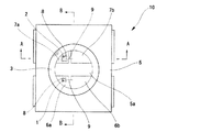
この発明の実施形態1に係る発光装置について、図1および図2に基づいて説明する。図1は実施形態1に係る発光装置の平面図、図2は図1のA−A断面図、図3は図1のB−B断面図である。
A light-emitting device according to
図1〜3に示されるように、実施形態1に係る発光装置10は、青色および赤色の波長の光をそれぞれ発光する青色LEDチップ1および赤色LEDチップ2と、青色および赤色LEDチップ1,2を封止する透光性の封止樹脂3とを備え、封止樹脂3は青色の波長の光によって励起され赤色の波長の光によって励起されない黄色蛍光体4を含有し、青色および赤色の波長の光と黄色蛍光体から発せられた黄色光との混色による白色と、赤色の波長の光とを選択的に発光できるように構成されている。
As shown in FIGS. 1 to 3, the
図1〜3に示されるように、青色LEDチップ1と赤色LEDチップ2は、基体5の凹部5aに収容されている。
凹部5aの底には、青色LEDチップ1および赤色LEDチップ2とそれぞれ電気的に導通をとるために、Agメッキが施された銅製のリードフレーム6a,6b,7a,7bがそれぞれ対をなすように延出している。
基体5は樹脂からなり、リードフレーム6a,6b,7a,7bはインサート成型により基体5と一体をなすように設けられている。
As shown in FIGS. 1 to 3, the
At the bottom of the
The
青色LEDチップ1および赤色LEDチップ2は、それらのカソード電極(図示せず)が一方のリードフレーム6a,7aとそれぞれ対向する関係となるようにリードフレーム6a,7a上にAgペースト8を介して搭載されている。
なお、カソード電極がAuSn又はSnからなる場合には、Agペースト8を使用することなく、リードフレーム6a,7a上に加熱による合金層を形成して直接接合することも可能である。
このような構成によれば、Agペースト8を使用する場合よりも、LEDチップ1,2からリードフレーム6a,7aへの熱伝導性が向上し、発熱に対する信頼性に優れた構造となる。
The
When the cathode electrode is made of AuSn or Sn, it is possible to form an alloy layer by heating on the lead frames 6a and 7a and directly bond them without using the
According to such a configuration, the thermal conductivity from the
一方、青色LEDチップ1と赤色LEDチップ2のアノード電極(図示せず)は、金線9によって他方のリードフレーム6b,7bにそれぞれワイヤボンディングされている。
これにより、青色LEDチップ1と赤色LEDチップ2は、1対のリードフレーム6a,6b,7a,7bとそれぞれ電気的に接続される。
On the other hand, anode electrodes (not shown) of the
Thereby, the
電気的に接続された青色LEDチップ1と赤色LEDチップ2は、外部からの衝撃や大気中の水分から保護される必要があるため封止樹脂3で封止される。
封止樹脂3は、黄色蛍光体4が分散混合された透明なエポキシ樹脂又はシリコーン樹脂からなり、電気的に接続された青色LEDチップ1と赤色LEDチップ2を埋設するように凹部5aに充填されている。
黄色蛍光体4は、青色LEDチップ1が発する青色の波長の光によって励起されて黄色光を発光する。
このため、青色LEDチップ1と赤色LEDチップ2が同時に発光すると、青色、黄色および赤色の光が同時に発せられることとなり、青色光と黄色光との混色による擬似的な白色光に赤色光の成分が加えられ、演色性が改善された白色光が発せられる。
The electrically connected
The sealing
The
For this reason, when the
また、上記の黄色蛍光体4は、赤色LEDチップ2が発する赤色光によっては励起されないため、赤色LEDチップ2のみが単独で点灯させられた際には赤色光のみが発光装置10から発せられる。
このように、実施形態1に係る発光装置10は、2色のLEDチップ1,2のみで青色光、黄色光および赤色光の混色による演色性が改善された白色光と、赤色光とを選択的に発光することができ、構成の簡易化によるコストの低減と、小型化による実装面積の減少を達成している。
Further, since the
As described above, the
実施形態2
この発明の実施形態2に係る発光装置について図4に基づいて説明する。図4は実施形態2に係る発光装置の断面図である。
図4に示されるように、実施形態2に係る発光装置20は、封止樹脂23が黄色蛍光体4を含有した第1層23aと、黄色蛍光体4を含有しない第2層23bとの積層構造を有し、青色LEDチップ1はその発光部1aが第1層23aに位置するように設けられ、赤色LEDチップ2はその発光部2aが第2層23bに位置するように設けられている。その他の構成は上述の実施形態1に係る発光装置10と同様である。
A light emitting device according to
As shown in FIG. 4, the
実施形態2に係る発光装置20は、黄色蛍光体4の励起に寄与しない赤色LEDチップ2の発光部2aが、黄色蛍光体4を含有しない第2層23bに位置するように設けられるので、赤色LEDチップ2から発せられた赤色光が蛍光体4に蹴られて遮られることがなくなり、出射効率の向上が図られている。
Since the
上述の実施形態1および2では、蛍光体として黄色蛍光体4を用いた例を説明したが、もちろん、黄色蛍光体4に代えて、青色の波長の光によって励起され緑色光を発する緑色蛍光体が用いられても構わない。
黄色蛍光体4に代えて緑色蛍光体が用いられた場合、光の3原色である赤色、緑色および青色の光の混色による白色光を発光することができ、より演色性に優れ、自然の光に近いものとなる。
また、上述の実施形態1および2では、表面実装型の発光装置10,20を例に説明したが、この発明の思想は上述の表面実装型に限られるものではなく、砲弾型など他の形態の発光装置にも適用できる。
In the first and second embodiments described above, an example in which the
When a green phosphor is used in place of the
In the first and second embodiments described above, the surface mount type
実施形態3
実施形態3は、上述の実施形態1又は2に係る発光装置10,20をカメラ付き携帯電話の補助光源として搭載したものである。図5は実施形態3に係るカメラ付き携帯電話の説明図である。
図5に示されるように、実施形態3に係るカメラ付き携帯電話30は、その一部にCCDカメラ31を備え、CCDカメラ31の近傍に補助光源として実施形態1又は2に係る発光装置10,20を搭載している。
In
As shown in FIG. 5, the
上述のとおり、実施形態1又は2に係る発光装置10,20は、白色光と赤色光とを選択的に発光できるため、撮影時の補助光源としての機能と、メール若しくは電話の着信、又は充電中であることを示す赤色ランプとしての機能とを果たすことができる。
また、実際の撮影時を除くカメラモード時には赤色光が点滅するように設定されており、周囲にカメラ付き携帯電話30が何らかの作動状態にあることを積極的に知らしめて、盗撮の防止が図られるように構成されている。
As described above, since the
Also, red light is set to flash in the camera mode except during actual shooting, so that the
図6は、実施形態3に係るカメラ付き携帯電話30のブロック図である。
図6に示されるように、CCDカメラ31および発光装置10,20は制御部32によって駆動・制御されている。制御部32は、撮影画像を表示する表示部33、ユーザーが操作するカメラモードスイッチ34、シャッター35および補助光源スイッチ36などとも接続されている。
FIG. 6 is a block diagram of the camera-equipped
As shown in FIG. 6, the
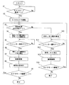
以下、制御部32が発光装置10,20を制御する制御フローについて、図7に示すフローチャート図に基づいて説明する。
Hereinafter, a control flow in which the
まず、カメラモードスイッチ34を介してカメラモードの要求がなされたか否かを判断する(ステップ1)。
ステップ1でカメラモードの要求がなされたと判断すると、CCDカメラ31を起動させてカメラモードとする(ステップ2)。
ステップ2でカメラモードになると、補助光源スイッチ36を介して補助光源の点灯要求がなされたか否かを判断する(ステップ3)。
First, it is determined whether a camera mode request has been made via the camera mode switch 34 (step 1).
If it is determined in
When the camera mode is set in
ステップ3で補助光源の点灯要求がなされたと判断すると、青色および赤色LEDチップ1,2を発光させ補助光源として白色光を発光させる(ステップ4)。
ステップ4で補助光源が発光させられると、シャッター35が操作されたか否かを判断する(ステップ5)。
ステップ5でシャッター35が操作されたと判断すると、CCDカメラ31に画像を撮像させる(ステップ6)。
ステップ6でCCDカメラ31に画像を撮像させると、補助光源を消灯させ(ステップ7)、カメラモードが継続されるか否かを判断し(ステップ8)、カメラモード継続の場合は先のステップ3に戻り、カメラモードが継続されないと判断した場合は一連のフローを終了する。
If it is determined in
When the auxiliary light source is caused to emit light in
If it is determined in
When the
一方、ステップ3で補助光源の点灯要求がなされなかった場合は、赤色LEDチップ2を間欠的に発光させる(ステップ9)。
ステップ9で赤色LEDチップ2を間欠的に発光させると、シャッター35が操作されたか否かを判断する(ステップ10)。
ステップ10でシャッター35が操作されたと判断すると赤色LED2の発光を止めさせ(ステップ11)、CCDカメラ31に画像を撮像させる(ステップ12)。
ステップ12でCCDカメラ31に画像を撮像させると、カメラモードが継続されるか否かを判断し(ステップ13)、カメラモード継続の場合は先のステップ3に戻り、カメラモードが継続されないと判断した場合は一連のフローを終了する。
On the other hand, if the auxiliary light source is not turned on in
If the
If it is determined in
When the
上述のフローでは、カメラモードで補助光源としての点灯要求がなされた場合には白色光が発せられ、補助光源としての点灯要求がなされなかった場合には実際の撮像時を除いて赤色光が点滅する。
これにより、補助光源としての点灯要求の有無に係わらず、カメラモード時には周囲にカメラ付き携帯電話30が何らかの作動状態にあることを光によって知らしめることができ、盗撮の防止を図ることができる。
In the above flow, white light is emitted when a lighting request is made as an auxiliary light source in the camera mode, and red light flashes except when actual imaging is made when no lighting request is made as an auxiliary light source. To do.
Thus, regardless of whether or not there is a lighting request as an auxiliary light source, it is possible to notify by light that the camera-equipped
なお、上述のフローでは補助光源として点灯要求がなされなかった場合にのみ赤色光が点滅するが、点灯要求がなされたか否かに係わらず赤色光を点滅させることもできる。その場合の制御フローについて図8に基づいて説明する。 In the above flow, the red light blinks only when the lighting request is not made as the auxiliary light source, but the red light can be blinked regardless of whether the lighting request is made. The control flow in that case will be described with reference to FIG.
まず、カメラモードスイッチ34を介してカメラモードの要求がなされたか否かを判断する(ステップ1)。
ステップ1でカメラモードの要求がなされたと判断すると、CCDカメラ31を起動させてカメラモードとする(ステップ2)。
ステップ2でカメラモードになると、補助光源スイッチ36を介して補助光源の点灯要求がなされたか否かを判断する(ステップ3)。
First, it is determined whether a camera mode request has been made via the camera mode switch 34 (step 1).
If it is determined in
When the camera mode is set in
ステップ3で補助光源の点灯要求がなされたと判断すると、青色LEDチップ1を間欠的に発光させると共に、赤色LEDチップ2を連続的に発光させる(ステップ4)。
ステップ4で青色LEDチップ1が間欠的に発光させられると共に赤色LEDチップが連続的に発光させられると、すなわち、白色光と赤色光が交互に点滅する状態となる。
ステップ4で白色光と赤色光が交互に点滅する状態となると、シャッター35が操作されたか否かを判断する(ステップ5)。
If it is determined that the auxiliary light source is requested to be turned on in
In
When white light and red light blink alternately in
ステップ5でシャッター35が操作されたと判断すると、青色LEDチップ1の間欠発光を連続発光に切り換えて通常の白色光を補助光源として発光させ(ステップ6)、CCDカメラ31に画像を撮像させる(ステップ7)。
ステップ7でCCDカメラ31に画像を撮像させると、補助光源を消灯させ(ステップ8)、カメラモードが継続されるか否かを判断し(ステップ9)、カメラモード継続の場合は先のステップ3に戻り、カメラモードが継続されないと判断した場合は一連のフローを終了する。
If it is determined in
When the
一方、ステップ3で補助光源の点灯要求がなされなかった場合は、赤色LEDチップ2を間欠的に発光させる(ステップ10)。
ステップ10で赤色LEDチップ2を間欠的に発光させると、シャッター35が操作されたか否かを判断する(ステップ11)。
ステップ11でシャッター35が操作されたと判断すると赤色LEDチップ2の発光を止めさせ(ステップ12)、CCDカメラ31に画像を撮像させる(ステップ13)。
ステップ13でCCDカメラ31に画像を撮像させると、カメラモードが継続されるか否かを判断し(ステップ14)、カメラモード継続の場合は先のステップ3に戻り、カメラモードが継続されないと判断した場合は一連のフローを終了する。
On the other hand, if the auxiliary light source is not turned on in
If the
If it is determined in step 11 that the
When the
以上のフローでは、補助光源の点灯要求の有無に係わらず、実際の撮像時を除くカメラモード時には赤色光の点滅状態となる。
これにより、カメラ付き携帯電話30の補助光源あるいは赤色光のLEDが何らかの作動状態にあることをより強く周囲に知らしめることができ、より一層の盗撮防止効果が得られる。
In the above flow, regardless of whether or not the auxiliary light source is requested to turn on, the red light blinks in the camera mode except during actual imaging.
As a result, the auxiliary light source of the camera-equipped
以上、実施形態1および2に係る発光装置10,20の使用例としてカメラ付き携帯電話30を例に説明したが、発光装置10,20の使用例はカメラ付き携帯電話30に限られるものではなく、デジタルカメラの補助光源に使用されても構わない。また、上述の低コストと小さな実装面積を活かして様々な機器の白色および赤色光源としても利用できる。
As described above, the camera-equipped
1・・・青色LEDチップ
1a,2a・・・発光部
2・・・赤色LEDチップ
3,23・・・封止樹脂
4・・・黄色蛍光体
5・・・基体
5a・・・凹部
6a,6b,7a,7b・・・リードフレーム
8・・・銀ペースト
9・・・金線
10,20・・・発光装置
23a・・・第1層
23b・・・第2層
30・・・カメラ付き携帯電話
31・・・CCDカメラ
32・・・制御部
33・・・表示部
34・・・カメラモードスイッチ
35・・・シャッター
36・・・補助光源スイッチ
DESCRIPTION OF
Claims (5)
Priority Applications (3)
| Application Number | Priority Date | Filing Date | Title |
|---|---|---|---|
| JP2007151921A JP5346448B2 (en) | 2007-06-07 | 2007-06-07 | LIGHT EMITTING DEVICE AND CAMERA MOBILE MOBILE WITH THE SAME |
| CN2008101096190A CN101320727B (en) | 2007-06-07 | 2008-06-06 | Light emitting device and camera-equipped cellular phone incorporating the same |
| US12/135,744 US7938550B2 (en) | 2007-06-07 | 2008-06-09 | Light emitting device and camera-equipped cellular phone incorporating the same |
Applications Claiming Priority (1)
| Application Number | Priority Date | Filing Date | Title |
|---|---|---|---|
| JP2007151921A JP5346448B2 (en) | 2007-06-07 | 2007-06-07 | LIGHT EMITTING DEVICE AND CAMERA MOBILE MOBILE WITH THE SAME |
Publications (2)
| Publication Number | Publication Date |
|---|---|
| JP2008305992A JP2008305992A (en) | 2008-12-18 |
| JP5346448B2 true JP5346448B2 (en) | 2013-11-20 |
Family
ID=40095703
Family Applications (1)
| Application Number | Title | Priority Date | Filing Date |
|---|---|---|---|
| JP2007151921A Expired - Fee Related JP5346448B2 (en) | 2007-06-07 | 2007-06-07 | LIGHT EMITTING DEVICE AND CAMERA MOBILE MOBILE WITH THE SAME |
Country Status (3)
| Country | Link |
|---|---|
| US (1) | US7938550B2 (en) |
| JP (1) | JP5346448B2 (en) |
| CN (1) | CN101320727B (en) |
Families Citing this family (16)
| Publication number | Priority date | Publication date | Assignee | Title |
|---|---|---|---|---|
| US8251814B2 (en) * | 2008-10-09 | 2012-08-28 | Aruze Gaming America, Inc. | Gaming machine having light emitting device |
| ES2777789T3 (en) * | 2008-11-06 | 2020-08-06 | Signify Holding Bv | Lighting device |
| JP5936810B2 (en) * | 2009-09-11 | 2016-06-22 | ローム株式会社 | Light emitting device |
| JP2011091158A (en) * | 2009-10-21 | 2011-05-06 | Olympus Corp | Light source device, electronic image acquisition device, electronic image observation device, endoscope device, and capsule endoscope device |
| KR100999809B1 (en) | 2010-03-26 | 2010-12-08 | 엘지이노텍 주식회사 | Light emitting device and light unit having thereof |
| US8210698B2 (en) * | 2010-07-28 | 2012-07-03 | Bridgelux, Inc. | Phosphor layer having enhanced thermal conduction and light sources utilizing the phosphor layer |
| CN102231377B (en) * | 2010-12-18 | 2012-07-11 | 木林森股份有限公司 | High color rendering light emitting diode and manufacture method thereof |
| US8851731B2 (en) * | 2011-10-24 | 2014-10-07 | Ningbo Baishi Electric Co., Ltd | Light-diffusion LED lamp |
| JP2014135437A (en) * | 2013-01-11 | 2014-07-24 | Panasonic Corp | Light-emitting module, lighting device, and lighting fixture |
| TWM458672U (en) * | 2013-04-10 | 2013-08-01 | Genesis Photonics Inc | Light source module |
| JP6764340B2 (en) | 2013-08-01 | 2020-09-30 | シグニファイ ホールディング ビー ヴィSignify Holding B.V. | Luminescent device with adapted output spectrum |
| JP6076958B2 (en) * | 2014-12-26 | 2017-02-08 | レノボ・シンガポール・プライベート・リミテッド | Method for suppressing voyeurism and portable electronic device |
| USD849732S1 (en) | 2017-04-27 | 2019-05-28 | R.A.M. Innovations, Llc | Lighting attachment for mobile electronic communications device |
| US20190393112A1 (en) * | 2018-06-25 | 2019-12-26 | Elizabeth Nofen | Encapsulant material containing fluorophores for in-situ visualization of stress in an organic package |
| CN109410754A (en) * | 2018-11-30 | 2019-03-01 | 武汉华星光电技术有限公司 | Light source assembly and the backlight module for using it |
| CN113508260B (en) * | 2019-01-09 | 2023-11-10 | 亮锐控股有限公司 | Lighting device for backlighting a display screen |
Family Cites Families (13)
| Publication number | Priority date | Publication date | Assignee | Title |
|---|---|---|---|---|
| US6577073B2 (en) * | 2000-05-31 | 2003-06-10 | Matsushita Electric Industrial Co., Ltd. | Led lamp |
| JP4386693B2 (en) * | 2000-05-31 | 2009-12-16 | パナソニック株式会社 | LED lamp and lamp unit |
| US20020191102A1 (en) * | 2001-05-31 | 2002-12-19 | Casio Computer Co., Ltd. | Light emitting device, camera with light emitting device, and image pickup method |
| JP3856221B2 (en) * | 2002-05-15 | 2006-12-13 | シャープ株式会社 | Mobile phone |
| JP2004317891A (en) * | 2003-04-17 | 2004-11-11 | Nec Saitama Ltd | Mobile electronic equipment with camera |
| JP4274843B2 (en) * | 2003-04-21 | 2009-06-10 | シャープ株式会社 | LED device and mobile phone device, digital camera and LCD display device using the same |
| US7318651B2 (en) * | 2003-12-18 | 2008-01-15 | Avago Technologies Ecbu Ip (Singapore) Pte. Ltd. | Flash module with quantum dot light conversion |
| JP5081370B2 (en) * | 2004-08-31 | 2012-11-28 | 日亜化学工業株式会社 | Light emitting device |
| JP2006135225A (en) * | 2004-11-09 | 2006-05-25 | Toshiba Corp | Light-emitting device |
| JP4715227B2 (en) * | 2005-02-21 | 2011-07-06 | パナソニック株式会社 | Manufacturing method of semiconductor light emitting device |
| JP4743844B2 (en) * | 2005-04-14 | 2011-08-10 | シチズン電子株式会社 | Light source |
| JP2007103402A (en) * | 2005-09-30 | 2007-04-19 | Sanyo Electric Co Ltd | Optical source |
| JP4017015B2 (en) * | 2007-02-13 | 2007-12-05 | 日亜化学工業株式会社 | Light emitting device |
-
2007
- 2007-06-07 JP JP2007151921A patent/JP5346448B2/en not_active Expired - Fee Related
-
2008
- 2008-06-06 CN CN2008101096190A patent/CN101320727B/en not_active Expired - Fee Related
- 2008-06-09 US US12/135,744 patent/US7938550B2/en not_active Expired - Fee Related
Also Published As
| Publication number | Publication date |
|---|---|
| US20080304262A1 (en) | 2008-12-11 |
| US7938550B2 (en) | 2011-05-10 |
| JP2008305992A (en) | 2008-12-18 |
| CN101320727A (en) | 2008-12-10 |
| CN101320727B (en) | 2010-06-16 |
Similar Documents
| Publication | Publication Date | Title |
|---|---|---|
| JP5346448B2 (en) | LIGHT EMITTING DEVICE AND CAMERA MOBILE MOBILE WITH THE SAME | |
| JP4309864B2 (en) | LIGHTING DEVICE, IMAGING DEVICE, AND PORTABLE TERMINAL | |
| US7679672B2 (en) | Electronic flash, imaging device and method for producing a flash of light having a wavelength spectrum in the visible range and the infrared range using a fluorescent material | |
| JP4896129B2 (en) | Light emitting device and alkaline earth metal sulfide phosphor for the same | |
| JP5909361B2 (en) | Matching LED flash to camera ambient light compensation algorithm | |
| US7176612B2 (en) | LED device and portable telephone, digital camera and LCD apparatus using the same | |
| JP4992250B2 (en) | Light emitting device | |
| TWI492413B (en) | A luminescent device | |
| JP2008010872A (en) | Led device having top surface heat dissipator | |
| WO2006135005A1 (en) | Light emitting device | |
| US20060082995A1 (en) | Device and method for producing output light having a wavelength spectrum in the infrared wavelength range and the visble wavelength range | |
| JP2006196777A (en) | Illuminator, imaging device, and portable terminal | |
| JP2010034183A (en) | Light-emitting device | |
| JP2004071807A (en) | Lighting device, camera system and portable apparatus | |
| JP2017017059A (en) | Light source for illumination and luminaire | |
| JP4854716B2 (en) | LED device, mobile phone device using the same, digital camera, and LCD display device | |
| JP2008270305A (en) | Light-emitting device | |
| JP2009543328A (en) | Light emitting element | |
| JP2007005549A (en) | White-light emitting diode lamp | |
| JP5125060B2 (en) | Light emitting device | |
| JP2007299775A (en) | Light-emitting unit and lighting apparatus | |
| JP2007179046A (en) | Camera apparatus and portable equipment | |
| JP2007017986A (en) | Device and method for producing output light having a wavelength spectrum in the infrared wavelength range and the visible wavelength range | |
| JP3474118B2 (en) | Light emitting diode and its lighting method | |
| JP4275701B2 (en) | Light emitting device and manufacturing method thereof |
Legal Events
| Date | Code | Title | Description |
|---|---|---|---|
| A621 | Written request for application examination |
Free format text: JAPANESE INTERMEDIATE CODE: A621 Effective date: 20090805 |
|
| A977 | Report on retrieval |
Free format text: JAPANESE INTERMEDIATE CODE: A971007 Effective date: 20110928 |
|
| A131 | Notification of reasons for refusal |
Free format text: JAPANESE INTERMEDIATE CODE: A131 Effective date: 20111004 |
|
| A521 | Request for written amendment filed |
Free format text: JAPANESE INTERMEDIATE CODE: A523 Effective date: 20111128 |
|
| A02 | Decision of refusal |
Free format text: JAPANESE INTERMEDIATE CODE: A02 Effective date: 20120417 |
|
| A521 | Request for written amendment filed |
Free format text: JAPANESE INTERMEDIATE CODE: A523 Effective date: 20120706 |
|
| A911 | Transfer to examiner for re-examination before appeal (zenchi) |
Free format text: JAPANESE INTERMEDIATE CODE: A911 Effective date: 20120717 |
|
| A912 | Re-examination (zenchi) completed and case transferred to appeal board |
Free format text: JAPANESE INTERMEDIATE CODE: A912 Effective date: 20120810 |
|
| A521 | Request for written amendment filed |
Free format text: JAPANESE INTERMEDIATE CODE: A523 Effective date: 20130510 |
|
| A521 | Request for written amendment filed |
Free format text: JAPANESE INTERMEDIATE CODE: A523 Effective date: 20130626 |
|
| A61 | First payment of annual fees (during grant procedure) |
Free format text: JAPANESE INTERMEDIATE CODE: A61 Effective date: 20130819 |
|
| R150 | Certificate of patent or registration of utility model |
Ref document number: 5346448 Country of ref document: JP Free format text: JAPANESE INTERMEDIATE CODE: R150 Free format text: JAPANESE INTERMEDIATE CODE: R150 |
|
| LAPS | Cancellation because of no payment of annual fees |