JP5345708B2 - Valve shaft leakage reduction structure - Google Patents
Valve shaft leakage reduction structure Download PDFInfo
- Publication number
- JP5345708B2 JP5345708B2 JP2011552235A JP2011552235A JP5345708B2 JP 5345708 B2 JP5345708 B2 JP 5345708B2 JP 2011552235 A JP2011552235 A JP 2011552235A JP 2011552235 A JP2011552235 A JP 2011552235A JP 5345708 B2 JP5345708 B2 JP 5345708B2
- Authority
- JP
- Japan
- Prior art keywords
- valve
- shaft
- fluid passage
- bearing
- valve shaft
- Prior art date
- Legal status (The legal status is an assumption and is not a legal conclusion. Google has not performed a legal analysis and makes no representation as to the accuracy of the status listed.)
- Active
Links
Images
Classifications
-
- F—MECHANICAL ENGINEERING; LIGHTING; HEATING; WEAPONS; BLASTING
- F16—ENGINEERING ELEMENTS AND UNITS; GENERAL MEASURES FOR PRODUCING AND MAINTAINING EFFECTIVE FUNCTIONING OF MACHINES OR INSTALLATIONS; THERMAL INSULATION IN GENERAL
- F16K—VALVES; TAPS; COCKS; ACTUATING-FLOATS; DEVICES FOR VENTING OR AERATING
- F16K1/00—Lift valves or globe valves, i.e. cut-off apparatus with closure members having at least a component of their opening and closing motion perpendicular to the closing faces
- F16K1/16—Lift valves or globe valves, i.e. cut-off apparatus with closure members having at least a component of their opening and closing motion perpendicular to the closing faces with pivoted closure-members
- F16K1/18—Lift valves or globe valves, i.e. cut-off apparatus with closure members having at least a component of their opening and closing motion perpendicular to the closing faces with pivoted closure-members with pivoted discs or flaps
- F16K1/22—Lift valves or globe valves, i.e. cut-off apparatus with closure members having at least a component of their opening and closing motion perpendicular to the closing faces with pivoted closure-members with pivoted discs or flaps with axis of rotation crossing the valve member, e.g. butterfly valves
- F16K1/226—Shaping or arrangements of the sealing
- F16K1/2268—Sealing means for the axis of rotation
-
- F—MECHANICAL ENGINEERING; LIGHTING; HEATING; WEAPONS; BLASTING
- F02—COMBUSTION ENGINES; HOT-GAS OR COMBUSTION-PRODUCT ENGINE PLANTS
- F02D—CONTROLLING COMBUSTION ENGINES
- F02D9/00—Controlling engines by throttling air or fuel-and-air induction conduits or exhaust conduits
- F02D9/08—Throttle valves specially adapted therefor; Arrangements of such valves in conduits
- F02D9/10—Throttle valves specially adapted therefor; Arrangements of such valves in conduits having pivotally-mounted flaps
- F02D9/1035—Details of the valve housing
- F02D9/106—Sealing of the valve shaft in the housing, e.g. details of the bearings
-
- F—MECHANICAL ENGINEERING; LIGHTING; HEATING; WEAPONS; BLASTING
- F02—COMBUSTION ENGINES; HOT-GAS OR COMBUSTION-PRODUCT ENGINE PLANTS
- F02M—SUPPLYING COMBUSTION ENGINES IN GENERAL WITH COMBUSTIBLE MIXTURES OR CONSTITUENTS THEREOF
- F02M26/00—Engine-pertinent apparatus for adding exhaust gases to combustion-air, main fuel or fuel-air mixture, e.g. by exhaust gas recirculation [EGR] systems
- F02M26/52—Systems for actuating EGR valves
- F02M26/53—Systems for actuating EGR valves using electric actuators, e.g. solenoids
- F02M26/54—Rotary actuators, e.g. step motors
-
- F—MECHANICAL ENGINEERING; LIGHTING; HEATING; WEAPONS; BLASTING
- F02—COMBUSTION ENGINES; HOT-GAS OR COMBUSTION-PRODUCT ENGINE PLANTS
- F02M—SUPPLYING COMBUSTION ENGINES IN GENERAL WITH COMBUSTIBLE MIXTURES OR CONSTITUENTS THEREOF
- F02M26/00—Engine-pertinent apparatus for adding exhaust gases to combustion-air, main fuel or fuel-air mixture, e.g. by exhaust gas recirculation [EGR] systems
- F02M26/65—Constructional details of EGR valves
- F02M26/70—Flap valves; Rotary valves; Sliding valves; Resilient valves
-
- F—MECHANICAL ENGINEERING; LIGHTING; HEATING; WEAPONS; BLASTING
- F02—COMBUSTION ENGINES; HOT-GAS OR COMBUSTION-PRODUCT ENGINE PLANTS
- F02M—SUPPLYING COMBUSTION ENGINES IN GENERAL WITH COMBUSTIBLE MIXTURES OR CONSTITUENTS THEREOF
- F02M26/00—Engine-pertinent apparatus for adding exhaust gases to combustion-air, main fuel or fuel-air mixture, e.g. by exhaust gas recirculation [EGR] systems
- F02M26/65—Constructional details of EGR valves
- F02M26/74—Protection from damage, e.g. shielding means
Landscapes
- Engineering & Computer Science (AREA)
- General Engineering & Computer Science (AREA)
- Mechanical Engineering (AREA)
- Chemical & Material Sciences (AREA)
- Combustion & Propulsion (AREA)
- Health & Medical Sciences (AREA)
- Toxicology (AREA)
- Details Of Valves (AREA)
- Exhaust-Gas Circulating Devices (AREA)
- Lift Valve (AREA)
Description
この発明は、排気ガス再循環(EGR)バルブ等の流体制御用バルブの軸洩れを低減させる軸洩れ低減構造に関する。 The present invention relates to a shaft leakage reduction structure for reducing shaft leakage of a fluid control valve such as an exhaust gas recirculation (EGR) valve.
昨今の環境問題に伴う排ガス規制強化によって、エンジンから発生するエミッションを抑えるために、例えばEGRバルブのような高温ガスが流通するバルブでは軸洩れを低減させることが必須となってきている。 Due to the tightening of exhaust gas regulations accompanying recent environmental problems, in order to suppress emissions generated from the engine, it is essential to reduce shaft leakage in a valve through which high-temperature gas such as an EGR valve flows.
従来、流体制御用バルブにおいて、ハウジングや軸受け部と弁軸との隙間を通って流体通路内の流体が洩出する軸洩れを抑えるために、この隙間にポリテトラフルオロエチレン(PTFE)若しくはフッ素系の軸シール又はラビリンスシール構造を設ける。例えば特許文献1に開示の軸洩れ低減構造では、弁軸の流体通路とハウジングの切替部分に設けた軸受け部の、流体通路側の弁軸外周にラビリンスシールを周設してジグザグ状の流体経路を形成し、流体が流体通路から軸受け部へ流れ出にくくすると共に、ハウジング側の弁軸外周にPTFEのリップシールを周設して、軸受け部からハウジングへの軸洩れを抑える。 Conventionally, in fluid control valves, polytetrafluoroethylene (PTFE) or fluorine-based valves are used in this gap in order to suppress shaft leakage in which fluid in the fluid passage leaks through the gap between the housing and the bearing portion and the valve shaft. A shaft seal or labyrinth seal structure is provided. For example, in the shaft leakage reduction structure disclosed in Patent Document 1, a labyrinth seal is provided around the outer periphery of the valve shaft on the fluid passage side of the bearing portion provided in the switching portion between the fluid passage of the valve shaft and the housing, and a zigzag fluid path. In order to prevent fluid from flowing out from the fluid passage to the bearing portion, a PTFE lip seal is provided around the outer periphery of the valve shaft on the housing side to suppress shaft leakage from the bearing portion to the housing.
しかしながら、EGRバルブに流通する高温ガスは200〜800℃、特にEGRクーラの直前に配置されるホットサイド用バルブに流通する高温ガスは800℃にも達するので、従来のPTFE又はフッ素系の軸シールでは耐熱温度を超えてしまい使用しにくい又は使用できないため、軸洩れ量を抑えることが困難であるという課題があった。 However, the high temperature gas flowing through the EGR valve reaches 200 to 800 ° C., and particularly the high temperature gas flowing through the hot side valve arranged just before the EGR cooler reaches 800 ° C. Therefore, the conventional PTFE or fluorine-based shaft seal However, since it exceeds the heat-resistant temperature and is difficult to use or cannot be used, there is a problem that it is difficult to suppress the amount of shaft leakage.
例えば特許文献1に開示の軸洩れ低減構造では、ラビリンスシールは軸受け部と弁軸の隙間を塞いでいないため、流体通路を流通する高温の排ガスはこの隙間から洩れ出てラビリンスシール部分に流体経路を形成してしまう。そのため、軸洩れを抑える役目は主にリップシールが果たすことになるが、このリップシールはPTFEのため、上述のように200〜800℃の高温ガスが流通するようなバルブでは使用できず、軸洩れ量を低減することができない。 For example, in the shaft leakage reduction structure disclosed in Patent Document 1, the labyrinth seal does not block the gap between the bearing portion and the valve shaft. Will be formed. Therefore, the role of suppressing the shaft leakage is mainly performed by the lip seal. However, since this lip seal is PTFE, it cannot be used in a valve through which a high-temperature gas of 200 to 800 ° C. circulates as described above. The amount of leakage cannot be reduced.
従って、特許文献1に開示の軸洩れ低減構造を高温(200℃以上)の流体に適用する場合には、ラビリンスシールはそのまま使用できるが、リップシールはPTFEから金属又は高温に耐えられる材料に変更する必要がある。ただし、その場合、リップシールと弁軸とのフリクションが増大して弁軸自体の動作に支障を与えることや、弁軸との隙間のシール構造が成立しないことが考えられ、高温下での軸洩れを低減させることは困難である。また、この構造は低温(200℃未満)の流体にも適用できるが、PTFEの軸シールと比較するとシール機能は劣る。ただし、コストは抑えられる。 Therefore, when the shaft leakage reduction structure disclosed in Patent Document 1 is applied to a high-temperature (200 ° C or higher) fluid, the labyrinth seal can be used as it is, but the lip seal is changed from PTFE to a metal or a material that can withstand high temperatures. There is a need to. However, in this case, the friction between the lip seal and the valve shaft may increase, which may impede the operation of the valve shaft itself, and the seal structure for the gap with the valve shaft may not be established. It is difficult to reduce leakage. This structure can also be applied to a low-temperature (less than 200 ° C.) fluid, but the sealing function is inferior to that of a PTFE shaft seal. However, the cost can be reduced.
この発明は、上記のような課題を解決するためになされたもので、バルブの軸洩れを低減させる軸洩れ低減構造を提供することを目的とする。 The present invention has been made to solve the above-described problems, and an object of the present invention is to provide a shaft leakage reduction structure that reduces the valve shaft leakage.
この発明の軸洩れ低減構造は、内部に設けた流体通路に連通する貫通穴を形成したハウジングと、貫通穴から流体通路に挿入され、回転中心軸を中心にして回転する弁軸と、弁軸と一体に回転して、流体通路を開閉する弁体と、弁軸の流体通路挿入側とは反対側で当該弁軸を回転自在に軸支するベアリングと、貫通穴内に設けられ、ベアリングより流体通路側で弁軸を回転自在に軸支する軸受け部と、ベアリングを、回転中心軸方向の流体通路とは反対側に荷重するワッシャと、弁軸の外周面に圧入され、与圧によって軸受け部の流体通路側の面に当接しながら回転する、切れ目のない環状の軸シール部とを備え、軸シール部は、ワッシャに荷重されたベアリングにより弁軸に作用する回転中心軸方向の流体通路とは反対側の与圧によって、軸受け部の流体通路側の面に当接すると共に、貫通穴を通じて流体通路から流れ出る流体の圧力が当該軸シール部に与圧として作用して軸受け部の流体通路側の面に当接するものである。
A shaft leakage reduction structure of the present invention includes a housing in which a through hole communicating with a fluid passage provided therein is formed, a valve shaft that is inserted into the fluid passage from the through hole and rotates about a rotation center shaft, and a valve shaft rotates integrally with a valve body for opening and closing the fluid communication path, the fluid passage insert side of the valve shaft and bearing for rotatably supporting the valve shaft on the opposite side, provided in the through hole, from the bearing A bearing that rotatably supports the valve shaft on the fluid passage side , a washer that loads a bearing on the opposite side of the fluid passage in the direction of the rotation center axis , and a pressure bearing that is press-fitted into the outer peripheral surface of the valve shaft. rotates while in contact with the surface of the fluid passage side parts, and a shaft seal part of the unbroken annular, axial seal section, the fluid passage of the rotation center axis direction acting on the valve shaft by a loaded bearing washer By the pressure on the opposite side, With the surface of the fluid passage side of the receiving portion abutting, in which the pressure of the fluid flowing out of the fluid passage in contact with the surface of the fluid passage side of the act as pressurized on the shaft seal section bearing portion through the through hole.
この発明によれば、弁軸の外周面に圧入された切れ目のない環状の軸シール部が、弁軸および当該軸シール部に作用する与圧によって、軸受け部の流体通路側の面に当接しながら回転することにより、弁軸と軸シール部の隙間及び軸受け部と軸シール部の隙間をなくして軸洩れを低減させるバルブの軸洩れ低減構造を提供することができる。
According to the present invention, the continuous annular shaft seal portion press-fitted into the outer peripheral surface of the valve shaft comes into contact with the surface of the bearing portion on the fluid passage side by the pressure acting on the valve shaft and the shaft seal portion. By rotating while rotating, it is possible to provide a valve shaft leakage reduction structure that reduces shaft leakage by eliminating the clearance between the valve shaft and the shaft seal portion and the clearance between the bearing portion and the shaft seal portion.
以下、この発明をより詳細に説明するために、この発明を実施するための形態について、添付の図面に従って説明する。
実施の形態1.
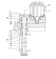
図1に示すEGRバルブは、バルブ開閉の回転駆動力を発生させるアクチュエータ部10と、アクチュエータ部10の駆動力をロッド(弁軸)32に伝達するギア部20と、高温の排ガスが流通する管(不図示)に介装され、バタフライ弁状のバルブ(弁体)37を開閉して排ガスの流通を制御するバルブ部30とからなる。
Hereinafter, in order to explain the present invention in more detail, modes for carrying out the present invention will be described with reference to the accompanying drawings.
Embodiment 1 FIG.
The EGR valve shown in FIG. 1 includes an
アクチュエータ部10はDCモータ等をモータ11に用い、このモータ11の駆動軸の一端には、ギア部ハウジング21内部にあるピニオンギア22が連結されている。モータ11が駆動するとピニオンギア22及びギア23が噛合して回転し、モータ11の駆動力をロッド32へ伝達する。ロッド32はベアリング25によって回転自在に軸支され、駆動力により回転中心軸Xを中心に回転して、ロッド32に固定されているバルブ37を開かせる。このベアリング25は、ワッシャ(荷重手段)26の荷重により軸方向上向きに与圧されている。また、ギア23にはリターンスプリング24が配置されており、このリターンスプリング24がロッド32をモータ11の駆動力による回転方向とは逆方向に付勢して、モータ11の停止中にバルブ37をバルブシート39に当接する閉位置へ戻す。
The
バルブ部ハウジング31には外部とガス通路(流体通路)38とを連通する貫通穴31aが設けられている。この貫通穴31aにロッド32が挿入される。また、この貫通穴31aにはブッシュ(軸受け部)35が圧入され、固定ピン34で固定されている。このブッシュ35が軸受けとなってロッド32を回転自在に軸支している。また、貫通穴31aにおいて、ロッド32の外周面にはプレート(軸シール部)36が圧入されており、ロッド32とプレート36が一体で回転する。また、バルブ部ハウジング31とギア部ハウジング21の間にはカバー33を配置して、ガスに含まれるカーボンデポジット、ゴミ等がロッド32の外周面に沿ってギア部ハウジング21内に進入しないようにする。
また、ロッド32にはバルブ37が固定されており、このバルブ37がロッド32と一体に回転して、ガス通路38に設けられたバルブシート39に当接してガスの流通を止める。
The
Further, a
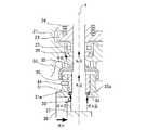
次に、図2及び図3の拡大断面図を用いて、EGRバルブの軸洩れ低減構造を説明する。
ガス通路38を流通するガス、及びバルブ37とバルブシート39の隙間から洩れ出るガスは、ロッド32の外周面に沿って軸方向上向きに軸洩れするが、プレート36がロッド32の外周面に圧入されているため、プレート36の内周面とロッド32の外周面に隙間がなく、この部分から軸洩れすることもない。
Next, the shaft leakage reduction structure of the EGR valve will be described with reference to enlarged sectional views of FIGS.
The gas flowing through the
また、ガス通路38を流通するガス、及びバルブ37とバルブシート39の隙間から洩れ出るガスは、ロッド32を外周面に沿って軸方向上向きに流通しながら与圧する。ロッド32に作用するこの与圧により、ロッド32と一体化したプレート36がブッシュ35へ当接する。このように、ロッド32に作用する与圧によりプレート36とブッシュ35とを積極的に当接させ、プレート36とブッシュ35の当接面の隙間を埋めることによって、ガスの洩れ出る経路をなくして軸洩れを抑えることができる。
Further, the gas flowing through the
さらに、ワッシャ26はベアリング25に荷重を与えているが、この荷重はベアリング25を経由してロッド32にも作用する。ワッシャ26によって発生されたこの与圧は、上記ガス圧力によって発生された与圧と共にロッド32に作用して、ロッド32と一体化したプレート36がブッシュ35へ当接する。従って、ガス圧力の変動時、例えばガス圧力が負圧になってブッシュ35とプレート36とが離れる方向に引っ張られる場合でも、ワッシャ26の荷重がプレート36を与圧するので軸洩れを抑えることができる。
Further, the
このように、ロッド32とプレート36を圧入すると共に、ロッド32に作用する与圧によりプレート36をブッシュ35に当接させて、ロッド32、プレート36、ブッシュ35の間でラビリンス構造を形成することにより、ガスの洩れ出る経路をなくして軸洩れ量を低減することができる。また、本構造をとることによってガスの圧力はプレート36とブッシュ35を密着させる方向に働くので、高圧下でも適用が可能である。また、ラビリンス構造形成に使用するプレートは、プレート36の1枚でよいため、従来のように複数枚のプレートを使用する場合に比べて部品点数、組立て工数、及びコストを抑えることができる。さらに、ロッド32を与圧することで、エンジン等からの振動又はガス通路38の圧力脈動を受けたロッド32、並びにこのロッド32と一体化したプレート36及びバルブ37が軸方向上下に振動することを抑えることができる。この結果、ブッシュ35とロッド32及びプレート36との当接面、並びにバルブシート39とバルブ37の当接面の磨耗を抑えることができる。
In this way, the
また、ガスの温度条件に応じてブッシュ35とプレート36の材料を選定して、200℃〜800℃の高温下でも軸洩れを低減させる。材料の候補としてはカーボン、金属、セラミック等があるが、高温ガスの場合にはブッシュ35及びプレート36共にステンレスが好ましく、低温の場合はカーボンでもよい。
Further, the material of the
さらに、ブッシュ35とプレート36の両材料の組み合わせ、硬度、コーディング及び表面処理を考慮して、ブッシュ35とプレート36の当接面の磨耗を抑制させる。例えばブッシュ35とプレート36を硬度が略同じか近い材料にしたり、さらにブッシュ35とプレート36の当接面をニッケルメッキ、ニッケルクロム、チッカ処理等の表面処理を施したりして、磨耗の低減を図る。
Further, in consideration of the combination of both materials of the
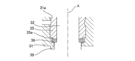
また、上記のような材料の選定及び表面処理以外にも、形状を考慮して当接面の磨耗を抑制するようにする。仮にブッシュ35の当接面の外径がプレート36の外径より大きければ、ブッシュ35が磨耗していくとブッシュ35とプレート36の当接部分に段差ができ、ロッド32が回転するときにブッシュ35とプレート36が噛み込み易くなる懸念がある。
そこで、ブッシュ35の軸方向下側の端部外径をプレート36の外径より小さくなるように縮径して、縮径端部35aを形成する。これにより、ブッシュ35に対してプレート36が回転して当接面が磨耗したとしても、段差がなく均一に磨耗するようになるので、ブッシュ35とプレート36の磨耗部分が噛み込んだり引っ掛かったりしにくい構造になっている。
In addition to the material selection and surface treatment as described above, the wear of the contact surface is suppressed in consideration of the shape. If the outer diameter of the contact surface of the
Therefore, the reduced
また、バルブ37のバルブシート39への位置決めは、バルブ37がバルブシート39に圧接することにより行うのではなく、ロッド32に一体化したプレート36がブッシュ35へ当接することにより行っているため、ロッド32の、バルブ37からブッシュ35とプレート36の当接位置までの距離が比較的短く、高温ガスの流通時に各部材が熱膨張により寸法変化があっても、その変化の影響を低減することができる。特にバルブ37が熱膨張で伸びた場合でもバルブシート洩れを抑えることができる。
In addition, the positioning of the
以上より、実施の形態1によれば、EGRバルブを、内部に設けたガス通路38に連通する貫通穴31aを形成したバルブ部ハウジング31と、貫通穴31aからガス通路38に挿入され、回転中心軸Xを中心にして回転するロッド32と、ロッド32と一体に回転してガス通路38のバルブシート39を開閉するバルブ37と、貫通穴31a内に設けられ、ロッド32を回転自在に軸支するブッシュ35と、ロッド32の外周面に圧入され、ロッド32に作用する与圧によってブッシュ35のガス通路38側の面に当接しながら回転するプレート36とを備えるように構成した。このため、ロッド32とプレート36の当接面は圧入により隙間をなくし、かつ、ロッド32に作用する与圧でブッシュ35とプレート36を当接させることにより、ガスの洩れ出る経路がロッド32、ブッシュ35及びプレート36からなるラビリンス構造となり、ロッド32とブッシュ35の隙間の軸洩れを低減させることができる。
As described above, according to the first embodiment, the EGR valve is inserted into the
また、実施の形態1によれば、ロッド32に作用する与圧を、貫通穴31aを通じてガス通路38から流れ出るガスの圧力によって発生させるようにしたので、ブッシュ35とプレート36を積極的に当接させて隙間を埋めることができ、よって軸洩れを低減させることができる。また、ガスの圧力はプレート36をブッシュ35に密着させる方向に働くので、高圧下ではシール力をより向上させて軸洩れをより低減することができる。さらに、エンジン等の振動又はガスの圧力脈動によるロッド32の軸方向の振れを抑制でき、結果として、ブッシュ35、プレート36及びロッド32の磨耗を抑えることができる。
Further, according to the first embodiment, the pressurizing force acting on the
また、実施の形態1によれば、EGRバルブが、ベアリング25を荷重することによってロッド32を回転中心軸Xの方向に荷重するワッシャ26を備え、ロッド32に作用する与圧はこのワッシャ26によって発生させるようにしたので、ブッシュ35とプレート36を積極的に当接させて隙間を埋めることができ、ガス圧力が変動した場合でも、軸洩れを低減させることができる。さらに、エンジン等の振動又はガスの圧力脈動によるロッド32の軸方向の振れを抑制でき、結果として、ブッシュ35、プレート36及びロッド32の磨耗を抑えることができる。
In addition, according to the first embodiment, the EGR valve includes the
また、実施の形態1によれば、ブッシュ35及びプレート36にガスの温度に応じた材料を使用することで、PTFE等が使用不可能な200℃〜800℃のガス温度にも適用でき、高温下でも軸洩れを低減することができる。
Further, according to the first embodiment, by using a material corresponding to the gas temperature for the
また、実施の形態1によれば、ブッシュ35及びプレート36に硬度が略同じ材料を使用したり、当接面それぞれに表面処理を施したりすることで、当接面の磨耗を抑えることができる。さらに、ブッシュ35のプレート36に当接する端面の外径をプレート36の外径より小さい縮径端部35aにすることで、仮に当接面が磨耗しても噛み込みにくく、引っ掛かりにくい構造にすることができる。
Further, according to the first embodiment, wear of the contact surfaces can be suppressed by using materials having substantially the same hardness for the
また、実施の形態1によれば、ブッシュ35とプレート36が当接することによってバルブ37の位置決めをするので、バルブ37の近くに位置決め部材、即ちブッシュ35とプレート36を配置して高温時の熱膨張による寸法変化の影響を低減することができる。
Further, according to the first embodiment, since the
以上のように、この発明に係る軸洩れ低減構造は、高温高圧下でも軸漏れを低減できるので、EGRバルブ等に用いるのに適している。 As described above, the shaft leakage reducing structure according to the present invention can reduce shaft leakage even under high temperature and high pressure, and is therefore suitable for use in an EGR valve or the like.
Claims (3)
前記貫通穴から前記流体通路に挿入され、回転中心軸を中心にして回転する弁軸と、
前記弁軸と一体に回転して、前記流体通路を開閉する弁体と、
前記弁軸の前記流体通路挿入側とは反対側で当該弁軸を回転自在に軸支するベアリングと、
前記貫通穴内に設けられ、前記ベアリングより前記流体通路側で前記弁軸を回転自在に軸支する軸受け部と、
前記ベアリングを、回転中心軸方向の前記流体通路とは反対側に荷重するワッシャと、
前記弁軸の外周面に圧入され、与圧によって前記軸受け部の前記流体通路側の面に当接しながら回転する、切れ目のない環状の軸シール部とを備え、
前記軸シール部は、前記ワッシャに荷重された前記ベアリングにより前記弁軸に作用する前記回転中心軸方向の前記流体通路とは反対側の与圧によって、前記軸受け部の前記流体通路側の面に当接すると共に、前記貫通穴を通じて前記流体通路から流れ出る流体の圧力が当該軸シール部に与圧として作用して前記軸受け部の前記流体通路側の面に当接することを特徴とするバルブの軸洩れ低減構造。 A housing in which a through hole communicating with a fluid passage provided therein is formed;
A valve shaft that is inserted into the fluid passage from the through hole and rotates about a rotation center axis;
A valve body that rotates integrally with the valve shaft to open and close the fluid passage;
A bearing that rotatably supports the valve shaft on the side opposite to the fluid passage insertion side of the valve shaft;
A bearing portion provided in the through hole and rotatably supporting the valve shaft on the fluid passage side from the bearing;
A washer for loading the bearing to the opposite side of the fluid passage in the direction of the rotation center axis ;
An annular shaft seal portion that is press-fitted into the outer peripheral surface of the valve shaft and rotates while being in contact with the surface on the fluid passage side of the bearing portion by pressurization , and
The shaft seal portion is applied to the surface of the bearing portion on the fluid passage side by a pressure applied to the valve shaft by the bearing loaded on the washer, opposite to the fluid passage in the rotation center axis direction. A shaft leakage of the valve , wherein the pressure of the fluid flowing out from the fluid passage through the through hole acts as a pressurizing force on the shaft seal portion and abuts the surface of the bearing portion on the fluid passage side. Reduction structure.
Applications Claiming Priority (1)
| Application Number | Priority Date | Filing Date | Title |
|---|---|---|---|
| PCT/JP2010/001047 WO2011101903A1 (en) | 2010-02-18 | 2010-02-18 | Structure for reducing axial leakage of valve |
Publications (2)
| Publication Number | Publication Date |
|---|---|
| JPWO2011101903A1 JPWO2011101903A1 (en) | 2013-06-17 |
| JP5345708B2 true JP5345708B2 (en) | 2013-11-20 |
Family
ID=44482530
Family Applications (1)
| Application Number | Title | Priority Date | Filing Date |
|---|---|---|---|
| JP2011552235A Active JP5345708B2 (en) | 2010-02-18 | 2010-02-18 | Valve shaft leakage reduction structure |
Country Status (6)
| Country | Link |
|---|---|
| US (1) | US20120193562A1 (en) |
| JP (1) | JP5345708B2 (en) |
| KR (1) | KR101310453B1 (en) |
| CN (1) | CN102575623B (en) |
| DE (1) | DE112010005282B4 (en) |
| WO (1) | WO2011101903A1 (en) |
Families Citing this family (17)
| Publication number | Priority date | Publication date | Assignee | Title |
|---|---|---|---|---|
| JP5924247B2 (en) * | 2012-11-27 | 2016-05-25 | 株式会社デンソー | Valve device |
| KR101362058B1 (en) * | 2012-12-17 | 2014-02-12 | 기아자동차 주식회사 | Exhaust gas recirculation valve for vehicle |
| DE102013013387A1 (en) * | 2013-03-10 | 2014-09-11 | Kohlhage Automotive GmbH & Co. KG | Bearing for a shaft, in particular in a valve unit, equipped with such a storage valve unit and method of manufacture |
| DE102013107111A1 (en) * | 2013-07-05 | 2015-01-08 | Pierburg Gmbh | Actuator for driving a valve unit of an internal combustion engine |
| JP6177114B2 (en) * | 2013-12-03 | 2017-08-09 | 三菱電機株式会社 | Exhaust gas recirculation valve |
| JP5847857B2 (en) * | 2014-01-14 | 2016-01-27 | 本田技研工業株式会社 | Reference position learning device for a valve of an internal combustion engine |
| JP6324870B2 (en) * | 2014-10-08 | 2018-05-16 | 東京エレクトロン株式会社 | Gas supply mechanism and semiconductor manufacturing apparatus |
| DE112014007122T5 (en) * | 2014-10-31 | 2017-07-13 | Mitsubishi Electric Corporation | Fluid control valve |
| DE102014226598A1 (en) * | 2014-12-19 | 2016-06-23 | Mahle International Gmbh | Valve device for controlling the flow of exhaust gas in an exhaust passage |
| DE102015111460B4 (en) * | 2015-05-07 | 2020-02-06 | BorgWarner Esslingen GmbH | Valve |
| DE102015111461B4 (en) * | 2015-05-07 | 2020-02-06 | BorgWarner Esslingen GmbH | Exhaust gas recirculation valve and method for improving such a valve |
| JP2017160889A (en) * | 2016-03-11 | 2017-09-14 | マツダ株式会社 | Exhaust system for engine |
| KR101836254B1 (en) * | 2016-03-16 | 2018-03-08 | 현대자동차 주식회사 | Exhaust gas recirculation valve device for vehicle |
| JP6597477B2 (en) * | 2016-05-24 | 2019-10-30 | 株式会社デンソー | Valve device |
| KR20190043004A (en) * | 2017-10-17 | 2019-04-25 | 현대자동차주식회사 | Exhaust gas recircuation valve |
| DE102017127793A1 (en) * | 2017-11-24 | 2019-05-29 | Pierburg Gmbh | Exhaust valve for an internal combustion engine |
| DE102020103420A1 (en) * | 2020-02-11 | 2021-08-12 | Friedrich Boysen GmbH & Co KG. | Flap device |
Citations (4)
| Publication number | Priority date | Publication date | Assignee | Title |
|---|---|---|---|---|
| JPS55106342U (en) * | 1979-01-19 | 1980-07-25 | ||
| JPH0394485U (en) * | 1990-01-16 | 1991-09-26 | ||
| JP2001221346A (en) * | 2000-02-09 | 2001-08-17 | Kubota Corp | Shaft seal structure of butterfly valve |
| JP2001234759A (en) * | 2000-02-22 | 2001-08-31 | Mikuni Corp | Throttle body shaft support structure |
Family Cites Families (14)
| Publication number | Priority date | Publication date | Assignee | Title |
|---|---|---|---|---|
| US2900995A (en) * | 1953-04-20 | 1959-08-25 | Rockwell Mfg Co | Jacketed valve |
| US2917271A (en) * | 1954-08-24 | 1959-12-15 | George W Banks | High pressure metering valve |
| US3326516A (en) * | 1964-03-17 | 1967-06-20 | Texsteam Corp | High pressure plug valve |
| US3753569A (en) * | 1971-03-23 | 1973-08-21 | A Bonomi | Pressure valve for fluids |
| US3851853A (en) * | 1973-04-23 | 1974-12-03 | Hoke Inc | Valve |
| DE2529641C3 (en) * | 1975-07-03 | 1982-01-21 | Fördertechnik Streicher GmbH, 7988 Wangen | Stopcock with axially adjustable cone plug |
| US4249555A (en) * | 1977-12-30 | 1981-02-10 | Domer Scaramucci | Fire safe disc valve |
| JPS63147538U (en) * | 1987-03-19 | 1988-09-28 | ||
| US5630571A (en) * | 1995-10-16 | 1997-05-20 | General Motors Corporation | Exhaust flow control valve |
| US5577709A (en) * | 1995-10-17 | 1996-11-26 | Henry Valve Company | Stem seal configuration for ball valves |
| CN2577055Y (en) * | 2002-07-22 | 2003-10-01 | 王建敏 | Frictionless hard-sealing butterfly valve |
| CN1629524A (en) * | 2003-12-15 | 2005-06-22 | 王加新 | Symmetrical butterfly valve adapted to ceramics or metal or engineering plastics manufacture |
| JP2005233023A (en) * | 2004-02-18 | 2005-09-02 | Denso Corp | Exhaust gas recirculation device |
| JP4621557B2 (en) * | 2005-07-22 | 2011-01-26 | 大豊工業株式会社 | Valve assembly |
-
2010
- 2010-02-18 WO PCT/JP2010/001047 patent/WO2011101903A1/en not_active Ceased
- 2010-02-18 JP JP2011552235A patent/JP5345708B2/en active Active
- 2010-02-18 KR KR1020127009328A patent/KR101310453B1/en not_active Expired - Fee Related
- 2010-02-18 DE DE112010005282.4T patent/DE112010005282B4/en active Active
- 2010-02-18 US US13/498,608 patent/US20120193562A1/en not_active Abandoned
- 2010-02-18 CN CN201080046961.6A patent/CN102575623B/en active Active
Patent Citations (4)
| Publication number | Priority date | Publication date | Assignee | Title |
|---|---|---|---|---|
| JPS55106342U (en) * | 1979-01-19 | 1980-07-25 | ||
| JPH0394485U (en) * | 1990-01-16 | 1991-09-26 | ||
| JP2001221346A (en) * | 2000-02-09 | 2001-08-17 | Kubota Corp | Shaft seal structure of butterfly valve |
| JP2001234759A (en) * | 2000-02-22 | 2001-08-31 | Mikuni Corp | Throttle body shaft support structure |
Also Published As
| Publication number | Publication date |
|---|---|
| DE112010005282T5 (en) | 2013-02-07 |
| US20120193562A1 (en) | 2012-08-02 |
| DE112010005282B4 (en) | 2015-02-19 |
| CN102575623A (en) | 2012-07-11 |
| KR20120065404A (en) | 2012-06-20 |
| CN102575623B (en) | 2015-06-17 |
| WO2011101903A1 (en) | 2011-08-25 |
| KR101310453B1 (en) | 2013-09-24 |
| JPWO2011101903A1 (en) | 2013-06-17 |
Similar Documents
| Publication | Publication Date | Title |
|---|---|---|
| JP5345708B2 (en) | Valve shaft leakage reduction structure | |
| CN102959294B (en) | Fluid control valve | |
| JP6062129B2 (en) | Fluid control valve | |
| CN104838112B (en) | Valve arrangement for internal combustion engine | |
| CN109312669B (en) | Exhaust gas flap arrangement for an internal combustion engine | |
| JP5304825B2 (en) | EGR valve | |
| JP5355792B2 (en) | Step type valve | |
| US20140252259A1 (en) | Butterfly valve | |
| KR20150082560A (en) | Overmoulded motorized valve with improved sealing | |
| US20110139132A1 (en) | Exhaust gas recirculation valve thrust collar | |
| JP2020128711A (en) | Cooling water control valve device | |
| JP2011196464A (en) | Ball valve type valve device | |
| JP5924247B2 (en) | Valve device | |
| JP2016501336A (en) | Flap device for internal combustion engine | |
| JP6247458B2 (en) | Vehicle exhaust gas recirculation valve | |
| JPWO2013008268A1 (en) | Valve shaft seal structure | |
| JP2012107572A (en) | Egr valve | |
| JP5664599B2 (en) | Valve device | |
| JP5185725B2 (en) | Steam valve for steam turbine | |
| JP2005256765A (en) | Exhaust control device for internal combustion engine | |
| JP2012052637A (en) | Fluid control valve | |
| EP2065573B1 (en) | Gasket for a valve of an internal combustion engine | |
| JP2012127207A (en) | Butterfly valve | |
| JP2017160880A (en) | Exhaust pipe shut-off valve device | |
| JP2016048050A (en) | EGR device |
Legal Events
| Date | Code | Title | Description |
|---|---|---|---|
| A02 | Decision of refusal |
Free format text: JAPANESE INTERMEDIATE CODE: A02 Effective date: 20120605 |
|
| A521 | Request for written amendment filed |
Free format text: JAPANESE INTERMEDIATE CODE: A523 Effective date: 20130612 |
|
| A61 | First payment of annual fees (during grant procedure) |
Free format text: JAPANESE INTERMEDIATE CODE: A61 Effective date: 20130814 |
|
| R150 | Certificate of patent or registration of utility model |
Ref document number: 5345708 Country of ref document: JP Free format text: JAPANESE INTERMEDIATE CODE: R150 Free format text: JAPANESE INTERMEDIATE CODE: R150 |
|
| R250 | Receipt of annual fees |
Free format text: JAPANESE INTERMEDIATE CODE: R250 |
|
| R250 | Receipt of annual fees |
Free format text: JAPANESE INTERMEDIATE CODE: R250 |
|
| R250 | Receipt of annual fees |
Free format text: JAPANESE INTERMEDIATE CODE: R250 |
|
| R250 | Receipt of annual fees |
Free format text: JAPANESE INTERMEDIATE CODE: R250 |
|
| R250 | Receipt of annual fees |
Free format text: JAPANESE INTERMEDIATE CODE: R250 |
|
| R250 | Receipt of annual fees |
Free format text: JAPANESE INTERMEDIATE CODE: R250 |
|
| R250 | Receipt of annual fees |
Free format text: JAPANESE INTERMEDIATE CODE: R250 |
|
| R250 | Receipt of annual fees |
Free format text: JAPANESE INTERMEDIATE CODE: R250 |
|
| S111 | Request for change of ownership or part of ownership |
Free format text: JAPANESE INTERMEDIATE CODE: R313111 |
|
| R250 | Receipt of annual fees |
Free format text: JAPANESE INTERMEDIATE CODE: R250 |
|
| R350 | Written notification of registration of transfer |
Free format text: JAPANESE INTERMEDIATE CODE: R350 |
|
| R250 | Receipt of annual fees |
Free format text: JAPANESE INTERMEDIATE CODE: R250 |