JP5341031B2 - Multi-cylinder rotary compressor, its assembling method and its manufacturing apparatus - Google Patents
Multi-cylinder rotary compressor, its assembling method and its manufacturing apparatus Download PDFInfo
- Publication number
- JP5341031B2 JP5341031B2 JP2010148848A JP2010148848A JP5341031B2 JP 5341031 B2 JP5341031 B2 JP 5341031B2 JP 2010148848 A JP2010148848 A JP 2010148848A JP 2010148848 A JP2010148848 A JP 2010148848A JP 5341031 B2 JP5341031 B2 JP 5341031B2
- Authority
- JP
- Japan
- Prior art keywords
- partition plate
- metal ring
- outer peripheral
- peripheral surface
- rotary compressor
- Prior art date
- Legal status (The legal status is an assumption and is not a legal conclusion. Google has not performed a legal analysis and makes no representation as to the accuracy of the status listed.)
- Expired - Fee Related
Links
Images


Description
この発明は、圧縮機構部の冷媒等媒体の漏れが少ない多気筒回転式圧縮機、その製造方法、及びその製造装置に関するものである。 The present invention relates to a multi-cylinder rotary compressor with little leakage of a medium such as a refrigerant in a compression mechanism section, a manufacturing method thereof, and a manufacturing apparatus thereof.
従来、多気筒回転式圧縮機として、特許文献1に示すものが提供されている。この多気筒回転式圧縮機は、電動要素(モータ)と複数個の回転圧縮要素(第1及び第2の回転圧縮要素)を密閉容器に収納し、電動要素と複数個の回転圧縮要素とを、偏心部を有するクランクシャフトで連結している。
そして、隣接する回転圧縮要素の間に介在する仕切板は2枚の分割板から成り、分割板に設けられた通し孔にクランクシャフトを挿通するようにクランクシャフトを取り囲んで組立を行った後、仕切板の外周に環状の熱収縮部材を嵌着して2枚の分割板を締結している。
特許文献1の多気筒回転式圧縮機によれば、クランクシャフトを取り囲んで組み立てた仕切板の外周に、環状の熱収縮部材を嵌着することにより、圧縮機の運転時にローラの摺動やシリンダの変形によって分割板間に微小な隙間が発生することを防止、抑制している。
Conventionally, what is shown in patent document 1 is provided as a multicylinder rotary compressor. In this multi-cylinder rotary compressor, an electric element (motor) and a plurality of rotary compression elements (first and second rotary compression elements) are housed in a sealed container, and the electric element and the plurality of rotary compression elements are combined. The crankshaft having an eccentric portion is connected.
And the partition plate interposed between the adjacent rotary compression elements is composed of two divided plates, and after assembling the crankshaft so as to insert the crankshaft into the through hole provided in the divided plate, An annular heat shrink member is fitted on the outer periphery of the partition plate to fasten the two divided plates.
According to the multi-cylinder rotary compressor of Patent Document 1, an annular heat-shrink member is fitted on the outer periphery of a partition plate that surrounds and assembles the crankshaft, so that the roller slides and cylinders are operated during the operation of the compressor. This prevents or suppresses the generation of minute gaps between the divided plates due to the deformation.
このような多気筒回転式圧縮機において用いられる環状の熱収縮部材は一般的に樹脂材料である。しかし、圧縮機内部は運転時と運転停止時での温度差が大きく、冷媒や冷凍機油が充満する環境においては、熱収縮部材では耐久性に問題があった。
また、仕切板は上下のシリンダによって挟まれボルトにより共締めされている構造であり、通常の運転状態において仕切板は上下のシリンダと仕切板間の摩擦力が働くため、仕切板に熱収縮部材による押圧力を加えることで微小な隙間の発生を抑制することが可能であるが、例えば吸入側の配管が閉塞している状態で運転する真空運転と呼ばれる特殊運転モードが発生した場合は、偏心部に装着したローラが冷却されず熱膨張する。
これにより、ローラと仕切板間の摺動性が悪化し、ローラと仕切板間の摩擦力が増加するとともに、シリンダや仕切板を固定するボルトの軸力がローラと仕切板の摺動面に集中する。その結果、シリンダと仕切板間の摩擦力が低下し、樹脂の熱収縮力では強度不足となる問題があった。もちろん樹脂以外の熱収縮部材を用いることにより耐久性や強度を確保する方法もありうるが、コストが高くなるため適切な方法ではない。
An annular heat shrink member used in such a multi-cylinder rotary compressor is generally a resin material. However, the internal temperature of the compressor has a large temperature difference between when it is in operation and when it is out of operation, and there is a problem with the durability of the heat-shrinkable member in an environment where the refrigerant and refrigerating machine oil are filled.
In addition, the partition plate is sandwiched between upper and lower cylinders and fastened together with bolts. In normal operation, the partition plate is subjected to frictional force between the upper and lower cylinders and the partition plate. It is possible to suppress the generation of minute gaps by applying a pressing force, but for example, when a special operation mode called vacuum operation that operates with the suction side piping closed is generated, The roller mounted on the part expands without being cooled.
As a result, the slidability between the roller and the partition plate deteriorates, the frictional force between the roller and the partition plate increases, and the axial force of the bolt that fixes the cylinder and the partition plate is applied to the sliding surface of the roller and the partition plate. concentrate. As a result, the frictional force between the cylinder and the partition plate is reduced, and there is a problem that the heat shrinkage force of the resin is insufficient. Of course, there may be a method of ensuring durability and strength by using a heat-shrinkable member other than resin, but this is not an appropriate method because the cost increases.
この発明は、上記のような問題点を解決するためになされたものであり、真空運転状態などシリンダと仕切板間の摩擦力が低下するような特殊運転モードであっても仕切板を構成する分割板間に隙間が発生しない多気筒回転式圧縮機を安価に得ることを目的としている。 The present invention has been made to solve the above-described problems, and constitutes the partition plate even in a special operation mode in which the frictional force between the cylinder and the partition plate is reduced, such as in a vacuum operation state. An object of the present invention is to obtain a multi-cylinder rotary compressor that does not generate a gap between divided plates at a low cost.
隣接する複数の圧縮機構を有し、それらの圧縮機構間を仕切る仕切板が複数に分割されているこの発明に係る多気筒回転式圧縮機は、
仕切板の外周面に嵌合された金属円環の内周面と仕切板の外周面の間に複数の空間を形成することを特徴とするものである。
The multi-cylinder rotary compressor according to the present invention has a plurality of adjacent compression mechanisms, and a partition plate that partitions between the compression mechanisms is divided into a plurality of
A plurality of spaces are formed between the inner peripheral surface of the metal ring fitted to the outer peripheral surface of the partition plate and the outer peripheral surface of the partition plate.
また、この発明に係る多気筒回転式圧縮機の製造方法は、
クランクシャフトが貫通するよう隣接する圧縮機構間に仕切板を組合せ、
仕切板の外周面に嵌合させる金属円環を、この金属円環の外周側から押圧して弾性変形させて仕切板の外周面に被せ、
金属円環の外周側からの押圧を解除することにより、金属円環の内周面と仕切板の外周面の間に複数の空間を形成することを特徴とするものである。
Moreover, the manufacturing method of the multi-cylinder rotary compressor according to the present invention is as follows:
Combine the partition plate between the adjacent compression mechanisms so that the crankshaft penetrates,
A metal ring to be fitted to the outer peripheral surface of the partition plate is pressed from the outer peripheral side of the metal ring and elastically deformed to cover the outer peripheral surface of the partition plate,
A plurality of spaces are formed between the inner peripheral surface of the metal ring and the outer peripheral surface of the partition plate by releasing the pressing from the outer peripheral side of the metal ring.
また、この発明に係る多気筒回転式圧縮機の製造装置は、
仕切板の外周面に嵌合させる金属円環を把持しつつ金属円環の外周側から押圧して弾性変形させ、
仕切板の外周面に被せた後、押圧を解除して仕切板に嵌合させ、
金属円環の内周面と仕切板の外周面の間に複数の空間を形成する仕切り板組み立て機構を有することを特徴とするものである。
Moreover, the manufacturing apparatus of the multi-cylinder rotary compressor according to the present invention includes:
While holding the metal ring to be fitted to the outer peripheral surface of the partition plate, press and elastically deform from the outer peripheral side of the metal ring,
After covering the outer peripheral surface of the partition plate, release the press and fit the partition plate,
It has a partition plate assembly mechanism that forms a plurality of spaces between the inner peripheral surface of the metal ring and the outer peripheral surface of the partition plate.
この発明に係る多気筒回転式圧縮機は、
仕切板の外周面に嵌合された金属円環の内周面と仕切板の外周面の間に複数の空間を形成することを特徴とするものなので、圧縮機の通常運転時はもとより、万が一特殊運転モードが起こったとしても仕切板を構成する分割板同士がずれず、再起動した際に性能が低下しない小型、大容量な多気筒回転式圧縮機を実現できる。
A multi-cylinder rotary compressor according to the present invention includes:
Since it is characterized in that a plurality of spaces are formed between the inner peripheral surface of the metal ring fitted to the outer peripheral surface of the partition plate and the outer peripheral surface of the partition plate, in the unlikely event of normal operation of the compressor. Even if the special operation mode occurs, it is possible to realize a small-sized and large-capacity multi-cylinder rotary compressor in which the partition plates constituting the partition plate are not displaced from each other and the performance is not deteriorated when restarted.
この発明に係る多気筒回転式圧縮機の製造方法は、
クランクシャフトが貫通するよう隣接する圧縮機構間に仕切板を組合せ、
仕切板の外周面に嵌合させる金属円環を、この金属円環の外周側から押圧して弾性変形させて仕切板の外周面に被せ、
金属円環の外周側からの押圧を解除することにより、金属円環の内周面と仕切板の外周面の間に複数の空間を形成することを特徴とするものなので、金属円環や仕切板を構成する分割板の加工精度が低くても、分割板同士を容易かつ確実に結合でき、仕切板からの冷媒漏れの少ない多気筒回転式圧縮機を提供できる。
The manufacturing method of the multi-cylinder rotary compressor according to the present invention is as follows:
Combine the partition plate between the adjacent compression mechanisms so that the crankshaft penetrates,
A metal ring to be fitted to the outer peripheral surface of the partition plate is pressed from the outer peripheral side of the metal ring and elastically deformed to cover the outer peripheral surface of the partition plate,
By releasing the pressure from the outer peripheral side of the metal ring, a plurality of spaces are formed between the inner peripheral surface of the metal ring and the outer peripheral surface of the partition plate. Even if the processing accuracy of the divided plates constituting the plates is low, the divided plates can be easily and reliably coupled to each other, and a multi-cylinder rotary compressor with little refrigerant leakage from the partition plate can be provided.
また、この発明に係る多気筒回転式圧縮機の製造装置は、
仕切板の外周面に嵌合させる金属円環を把持しつつ金属円環の外周側から押圧して弾性変形させ、
仕切板の外周面に被せた後、押圧を解除して仕切板に嵌合させ、
金属円環の内周面と仕切板の外周面の間に複数の空間を形成する仕切り板組み立て機構を有することを特徴とするものなので、複数の分割板で構成する仕切板の外周面に金属円環を容易に嵌め合わせることができる。
Moreover, the manufacturing apparatus of the multi-cylinder rotary compressor according to the present invention includes:
While holding the metal ring to be fitted to the outer peripheral surface of the partition plate, press and elastically deform from the outer peripheral side of the metal ring,
After covering the outer peripheral surface of the partition plate, release the press and fit the partition plate,
Since it has a partition plate assembling mechanism that forms a plurality of spaces between the inner peripheral surface of the metal ring and the outer peripheral surface of the partition plate, metal is provided on the outer peripheral surface of the partition plate composed of a plurality of divided plates. Rings can be easily fitted together.
実施の形態1.
以下、この発明に係る多気筒回転式圧縮機の実施の形態1を図を用いて説明する。
図1は、多気筒回転式圧縮機100(以下、ロータリ圧縮機100という)の縦断面図である。
図2は、図1のロータリ圧縮機100をA−A線で切断した横断面図である。
本実施の形態では、2つの圧縮室を有する冷凍・空調機用ロータリ圧縮機を例に挙げて説明する。
ロータリ圧縮機100は、密閉容器であるシェル101と、このシェル101の内部に設置した駆動源であるモータ102及び2基の圧縮機構部で構成する圧縮装置103を備える。
Embodiment 1 FIG.
A first embodiment of a multi-cylinder rotary compressor according to the present invention will be described below with reference to the drawings.
FIG. 1 is a longitudinal sectional view of a multi-cylinder rotary compressor 100 (hereinafter referred to as a rotary compressor 100).
FIG. 2 is a cross-sectional view of the
In the present embodiment, a rotary compressor for a refrigeration / air conditioner having two compression chambers will be described as an example.
The
シェル101は、上部シェル101aと中間シェル101bと下部シェル101cを有する。
上部シェル101aには、外部からモータ102に電力を供給するためのガラス端子104と、圧縮された冷媒を圧縮機外部へ吐出する吐出パイプ105を設けている。
中間シェル101b内には、モータ102と圧縮装置103が固定されており、圧縮装置103へ冷媒を導く吸入パイプ106が中間シェル101bの壁面を貫通して固定されている。
吸入パイプ106は、吸入マフラ107に接続されており、吸入マフラ107内で冷媒の気液分離、及び冷媒中のゴミの除去が行われる。
The
The
A
The
モータ102は、固定子102aと回転子102bを備え、回転子102bはクランクシャフト108に取り付けられている。モータ102で発生した回転トルクはクランクシャフト108を通して圧縮装置103に伝達される。
The
圧縮装置103は、先述のモータ102の回転軸でもあるクランクシャフト108、第1の軸受109aが内周部に形成された第1の枠体109、第1のシリンダ110a、第1のバネ111a、第1のベーン112a、第1のローラ113a、仕切板114、第2のシリンダ110b、第2の軸受116aが内周部に形成された第2の枠体116、第2のバネ111b、第2のベーン112b、第2のローラ113bを有しており、短いボルト133と長いボルト134により上下から締結されている。
The
クランクシャフト108は、ロータ嵌合部120、第1の軸受挿入部121、第1の偏心部122a、中間部123、第2の偏心部122b、第2の軸受挿入部125を有している。第1の偏心部122aと第2の偏心部122bは、偏心位相が180度異なっており、それぞれの外周面には第1のローラ113aと第2のローラ113bが回転自在に取り付けられている。
The
第1の枠体109の下端面、第1のシリンダ110aの内周面、仕切板114の上端面、及び第1のローラ113aの外周面で囲まれる空間が第1の圧縮室126aとなる。
同様に、仕切板114の下端面、第2のシリンダ110bの内周面、第2の枠体116の上端面、及び第2のローラ113bの外周面で囲まれる空間が第2の圧縮室126bとなる。
A space surrounded by the lower end surface of the
Similarly, a space surrounded by the lower end surface of the
図2に示すように、第1のシリンダ110a及び第2のシリンダ110bには径方向に伸縮する第1のバネ111a及び第2のバネ111bが取り付けられており、各バネの押し付け力により第1のベーン112a及び第2のベーン112bが第1のローラ113a及び第2のローラ113bの外周面に押し付けられる。第1のベーン112a及び第2のベーン112bは第1の圧縮室126a及び第2圧縮室126bを低圧部分128と高圧部分129に分ける機能を持つ。尚、本例では第1のベーン112aと第2のベーン112bの位相は等しい。
As shown in FIG. 2, a
図3は、第1の圧縮室126aと第2の圧縮室126bの間を仕切る仕切板114を構成する2枚の分割板130、131を示す斜視図である。
図3に示すように、仕切板114は分割板130及び分割板131を組み合わせている。分割板130は、上端面130a、下端面130b、分割面130c、及び外周面130dを有する。分割面130cにはクランクシャフト108挿入用の溝130eがある。外周面130dには3箇所の切り欠きがある。
第2の分割板131は、上端面131a、下端面131b、分割面131c、及び外周面131dを有する。分割面131cにはクランクシャフト108挿入用の溝131eがある。外周面131dには3箇所の切り欠きがある。分割板130及び分割板131には圧縮装置103の組立に用いられるボルト締結用の通し穴130f及び131fが複数個(本例ではそれぞれ3個ずつ)設けられている。
FIG. 3 is a perspective view showing two divided
As shown in FIG. 3, the
The second divided
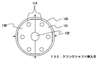
図4は、第1の圧縮室126aと第2の圧縮室126bの間を仕切る仕切板114に金属円環135を取り付けた状態を示す平面図である。
分割板130及び分割板131は、分割面130c及び分割面131cが接触した状態で組み合わされ、外周面130d、131dには1個の金属円環135が嵌合している。
仕切板114と金属円環135の嵌合に締め代を設定することにより、仕切板114の分割面に締め代に応じた押し付け力が働き、分割板130と分割板131とが接合部でずれることを防止する。
FIG. 4 is a plan view showing a state in which a
The dividing
By setting the tightening allowance for the fitting of the
上述の「押し付け力」を説明するために、図4の金属円環135を取り外す方法を説明する。
図の4箇所の矢印方向から金属円環135を押圧する。押圧する部分の金属円環135の内側は円弧状の空間になっている。この空間に接する金属円環135の内周面の周方向の長さは、対面する切り欠き部分の長さより長い。したがって4箇所の矢印部分を押圧すると、金属円環135が仕切板114に接触している部分は、金属円環135の径方向外側に膨らむ。すると、仕切板114の外周面と金属円環135の内周面の間に隙間ができて金属円環135を取り外すことができる。
金属円環135の取り付けはこの反対の手順で行うのであるが、金属円環135に対する押圧を開放すると、金属円環135の内周面が上述の空間に対面する部分がバネとなって金属円環135の締め代を吸収する。
In order to explain the “pressing force” described above, a method of removing the
The
The
分割板130の溝130eと分割板131の溝131eとが向かい合わせとなり、クランクシャフト挿入孔132を形成する。
クランクシャフト挿入孔132の径はクランクシャフト108の中間部123の径よりやや大きく、第1の偏心部122a及び第2の偏心部122bの径より小さい。
The
The diameter of the
このような構造であるため、クランクシャフト108の偏心部122a、122bの偏心量が大きいものであっても、クランクシャフト挿入孔132の径を小さくすることができ、クランクシャフト挿入孔132からの冷媒漏れを少なくすることができる。
本実施の形態のロータリ圧縮機100は、ガラス端子104からの通電によりシェル101内部に設置されたモータ102を駆動して、第1の偏心部122a及び第2の偏心部122bを有するクランクシャフト108を回転させる。
そして冷媒は、吸入マフラ107及び吸入パイプ106を通じて第1の圧縮室126a並びに第2圧縮室126bに吸入され、クランクシャフト108の回転に伴って圧縮され、一定の圧力になると吐出口136からシェル101内部へ吐出され、さらに吐出パイプ105よりロータリ圧縮機100外部へ吐出される。
Because of such a structure, even if the
The
Then, the refrigerant is sucked into the
図5に圧縮装置103のボルト締結構造の詳細を示す。第1の枠体109と第1のシリンダ110a、第2の枠体116と第2のシリンダ110bがそれぞれ3本ずつの短いボルト133で固定されている。また第1の枠体109と第2シリンダ110b、第2の枠体116と第1のシリンダ110aがそれぞれ3本ずつの長いボルト134で固定されており、仕切板114は第1のシリンダ110aと第2のシリンダ110bに挟まれた状態で共締めされている。そのため仕切板114には軸方向の締付力と水平方向の摩擦力が働く。
FIG. 5 shows details of the bolt fastening structure of the
ロータリ圧縮機100の運転時には、ローラ113a、113bが仕切板114の板面上を摺動する。この時、仕切板114を構成する分割板130と分割板131がずれようとする力(ずれ力)F1に対して、シリンダ110a、110bと仕切板114間の摩擦力と金属円環135による押し付け力の和がずれ耐力F2となる。
ずれ耐力F2がずれ力F1より大きいことによって仕切板114はずれない。一般に通常運転時のずれ耐力F2は、ずれ力F1よりも十分大きくなるよう設計している。
しかしながら、真空運転と呼ばれる特殊運転モードが発生した場合においては、ローラ113a、113bと仕切板114間の摺動性が悪化し、ローラ113a、113bと仕切板114間の摩擦力が大きくなるとともに、シリンダ110a、110bと仕切板114間の摩擦力が低下するため、ずれ耐力F2をずれ力F1より大きくするのは困難である。
During operation of the
Since the displacement tolerance F2 is larger than the displacement force F1, the
However, when a special operation mode called vacuum operation occurs, the slidability between the
以下、真空運転発生時の圧縮装置103について詳細に説明する。
真空運転は、圧縮装置103の冷媒流路の上流側が何らかの理由で閉塞した状態でロータリ圧縮機100を運転した場合に生じる特殊運転モードである。
冷媒が吸入されない状態で冷媒を圧縮しようとするため圧縮装置103の内部が部分的に真空に近くなる。そのためローラ113a、113bとベーン112a、112bの摺動部が冷媒によって冷却されず、ローラ113a、113bが加熱されて熱膨張し、仕切板114と枠体109、116をクランクシャフト108の軸方向に押すことによって長いボルトの軸力がローラ113a、113bと仕切板114の摺動面に集中し、シリンダ110a、110bと仕切板114間の摩擦力が低下する。
ローラ113a、113bとシリンダ110a、110bの厚さに微小な差をつけて、クリアランスを設けることで、真空運転時における当該摩擦力の低下を低減することは可能である。
しかし、クリアランスが大きくなると通常運転時にローラ113a、113bとシリンダ110a、110b間の隙間が大きくなり、圧縮性能が低下するというトレードオフの関係となる。
Hereinafter, the
The vacuum operation is a special operation mode that occurs when the
Since the refrigerant is to be compressed in a state where the refrigerant is not sucked, the inside of the
By providing a clearance by making a small difference in the thickness of the
However, when the clearance is increased, the gap between the
このような特殊運転モードが起こった場合、モータ102に流れる電流が増大するため、過電流を検知してロータリ圧縮機100の運転を止めることは可能である。
運転を停止するまでの間に仕切板114がずれなければ、流路の閉塞を取り除いて再起動をする。この場合、圧縮装置103の性能が低下することはない。
しかし、運転を止めるまでの間に仕切板114の合わせ目がずれれば、分割板130と分割板131の間に隙間ができてしまう。この場合は、流路の閉塞を取り除いてロータリ圧縮機100を再起動したとしても圧縮性能が低下することになる。
When such a special operation mode occurs, the current flowing through the
If the
However, if the joint of the
仕切板114の外周に金属円環135を嵌合することでずれ耐力は向上する。したがって金属円環135の嵌合は締め代の管理が重要である。仕切板114の外周や金属円環135の内周の寸法にばらつきが大きい場合、締め代のばらつきも大きくなり、金属円環135の取り付けが困難になる。
従って一般的には、部品間の寸法精度を維持するために、切削加工などの機械加工が必要となる。
しかし本発明の実施の形態1においては、仕切板114外周に切り欠きを設けることで仕切板114の外周面や金属円環135内周面の機械加工を不要とし、コストの低減を可能としている。
By fitting the
Therefore, in general, machining such as cutting is required to maintain dimensional accuracy between components.
However, in the first embodiment of the present invention, by providing a notch on the outer periphery of the
仕切板114外周に切り欠きを設けることで仕切板114と金属円環135の嵌合が部分的となり、装着時に金属円環135の切り欠き部に対向する箇所を変形させることによって締め代を調整できる。従って、金属円環自体のばらつきが大きい場合でも容易に組立てることができる。量産時において、例えばプレス加工等、安価だが寸法精度が悪い加工法を用いても仕切板114や金属円環135を製造することが可能となる。
また、板材をロールして溶接して円環形状とし、この内周を拡管して金属円環135を製造しても良く、切削機械加工によって製造するよりも安価に製造できる。
圧縮機の通常運転時はもとより万が一特殊運転モードが起こったとしても仕切板114を構成する分割板130,131同士がずれず、再起動した際に圧縮性能が低下しない小型、大容量な多気筒回転式圧縮機を実現できる。
なお、これまで分割板130,131の外周に3箇所の切り欠きがある場合について説明したが、切り欠きの数は3箇所に限ることはなく、例えば図4における上下2箇所の部分だけでも良いし、図6のように5つやそれ以上であってもよい。
By providing a notch on the outer periphery of the
Further, the
Even if a special operation mode occurs in the normal operation of the compressor, the divided
In addition, although the case where there were three cutouts on the outer periphery of the divided
次に、ロータリ圧縮機100の圧縮装置103の、組み立て装置を用いた製造方法について図を用いて説明する。
図7は組み立て中の圧縮装置103とその組立装置200の使用状態を示す図である。
Next, the manufacturing method using the assembly apparatus of the
FIG. 7 is a diagram illustrating a use state of the
組立装置200は主としてベース201、ワーク位置決め部品202、仕切板押圧機構203(以下、押圧機構203という)、把持挿入機構204から構成される。圧縮装置103は上下逆転した状態でベース201にセットされる。ベース201上にあるワーク位置決め部品202は、第1のシリンダの側面にこれを当てることでクランクシャフト108の中心軸の位置決めをするために使用する。
押圧機構203は、上方から仕切板114を第1のシリンダ110aに押し付け、圧縮装置103を組立中に仕切板114を構成する分割板130と分割板131がずれないようにこれらを固定する。
把持挿入機構204は、各部品を把持、挿入する機構を有し、特に金属円環135の外周を把持してわずかに変形させる機構と、把持した金属円環135を仕切板114の外周に挿入する機構も有する。
The assembling
The
The
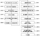
図8は、組立装置200の動作シーケンスを示す図である。
フローチャートに従い組立装置200の動作を説明する。
まずSTEP1において、前工程でボルト133により固定された第1のシリンダ110aと第1の枠体109を、ベース201上に図1及び図5とは天地を反転させた状態で把持挿入機構204を用いて載置する。STEP2では、ベース201上のワーク位置決め部品202により、第1の軸受109aの中心軸が所定の位置となるよう第1のシリンダ110aの位置決めをする。
FIG. 8 is a diagram illustrating an operation sequence of the assembling
The operation of the assembling
First, in STEP 1, the
次に、STEP3において第1のシリンダ110aに第1ベーン112aと第1のローラ113aを挿入する。
次にSTEP4では、クランクシャフト108を第1の枠体109の第1の軸受109aに挿入し、クランクシャフト108の第1の偏心部122aを第1のシリンダ110a内の第1のローラ113aに挿入する。
次にSTEP5では、第1のシリンダ110a上に分割板130と分割板131をセットする。この際、分割板130と分割板131の位相と位置を決める。
Next, in STEP 3, the
Next, in STEP4, the
Next, in STEP 5, the dividing
次にSTEP6では、押圧機構203により上方から仕切板114に荷重を負荷し、これを第1のシリンダ110aに押し付ける。
次にSTEP7では、把持挿入機構204により金属円環135を把持する。把持挿入機構204は、金属円環135の外周を、仕切板114の切り欠きに対向する部分に相当する4方向から把持する。
次にSTEP8では、把持挿入機構204の把持力を増加、調整し、金属円環135を仕切板114の切り欠き部分の形状に沿うように弾性変形させる。
具体的には、把持している箇所が凹み、仕切板114と嵌合する箇所を膨らませる。
Next, in STEP 6, a load is applied to the
Next, in
Next, in STEP 8, the gripping force of the
Specifically, the gripping portion is recessed, and the portion that fits with the
次にSTEP9では、把持挿入機構204を下降させて金属円環135を仕切板114の外周に嵌め合わせる。STEP8において、仕切板114と嵌合する箇所が膨らむように金属円環135を変形させているため、仕切板114の外周と金属円環135の内周の嵌合のための締め代が金属円環135に設けられていても、金属円環135をスムーズに仕切板114の外周に挿入することが可能となる。
また、STEP6において押圧機構203により仕切板114を第1のシリンダに押し付けているため、金属円環135の挿入によって分割板130と分割板131が互いにずれることはない。
Next, in STEP 9, the
Further, since the
次にSTEP10では、把持挿入機構204による金属円環135の把持を外し、把持挿入機構204を上昇させる。
その後、STEP11で押圧機構203を上方に退避させ、STEP12でクランクシャフト108の偏心部122bに第2のローラ113bを挿入する。
STEP13では、第2のベーン112bをセットした第2のシリンダ110bを仕切板114上に載置し、第2枠体116に設けられた第2の軸受116aをクランクシャフト108に挿入する。
Next, in STEP 10, the grasping / inserting
Thereafter, the
In STEP 13, the
STEP14では、第1軸受と第2軸受の中心が同軸となるように第2のシリンダ110bの位置決めを行う。
最後にSTEP15において、ボルト134により第1の枠体109と第2のシリンダ110b、及び第2の枠体116と第2のシリンダ110bをそれぞれ固定する。
In STEP 14, the
Finally, in STEP 15, the
このように、組立装置200を使用した圧縮装置103の製造方法によると、第1の分割板130と第2の分割板131から構成される仕切板114に金属円環135を容易に嵌め合わせることができる。特に仕切板114外周に切り欠きを設け、金属円環135の切り欠きに向かい合う位置をわずかに変形させ、仕切板114と嵌め合う箇所を弾性変形で膨らませることにより、例え仕切板114の外周と、金属円環135の内周の寸法精度が多少悪い場合でも、圧入や焼嵌めを行う必要がなく安価な設備で容易に製造することができる。
Thus, according to the manufacturing method of the
以上、本発明の実施の形態1によれば、ロータリ圧縮機100の圧縮装置103のシリンダ間を仕切る仕切板114の継ぎ目からの冷媒漏れが少なく、信頼性の高い小型大容量の多気筒回転式圧縮機を安価に提供することができる。
As described above, according to the first embodiment of the present invention, there is little refrigerant leakage from the joint of the
100 ロータリ圧縮機、101 シェル、101a 上部シェル、
101b 中間シェル、101c 下部シェル、102 モータ、102a 固定子、
102b 回転子、103 圧縮装置、104 ガラス端子、105 吐出パイプ、
106 吸入パイプ、107 吸入マフラ、108 クランクシャフト、
109 第1の枠体、109a 第1の軸受、110a,110b シリンダ、
111a,111b バネ、112a,112b ベーン、
113a,113b ローラ、114 仕切板、116 第2の枠体、
116a 第2の軸受、120 ロータ嵌合部、121 軸受挿入部、
122a,122b 偏心部、123 中間部、125 軸受挿入部、
126a 圧縮室、126b 圧縮室、128 低圧部分、129 高圧部分、
130,131 分割板、130a 上端面、130b 下端面、130c 分割面、
130d 外周面、130e 溝、130f 穴、131a 上端面、
131b 下端面、131c 分割面、131d 外周面、131e 溝、
132 クランクシャフト挿入孔、133,134 ボルト、135 金属円環、
136 吐出口、200 組立装置、201 ベース、202 ワーク位置決め部品、
203 仕切板押圧機構、204 把持挿入機構。
100 rotary compressor, 101 shell, 101a upper shell,
101b Intermediate shell, 101c Lower shell, 102 Motor, 102a Stator,
102b Rotor, 103 compression device, 104 glass terminal, 105 discharge pipe,
106 suction pipe, 107 suction muffler, 108 crankshaft,
109 first frame, 109a first bearing, 110a, 110b cylinder,
111a, 111b springs, 112a, 112b vanes,
113a, 113b roller, 114 partition plate, 116 second frame,
116a 2nd bearing, 120 rotor fitting part, 121 bearing insertion part,
122a, 122b eccentric part, 123 middle part, 125 bearing insertion part,
126a compression chamber, 126b compression chamber, 128 low pressure portion, 129 high pressure portion,
130, 131 dividing plate, 130a upper end surface, 130b lower end surface, 130c dividing surface,
130d outer peripheral surface, 130e groove, 130f hole, 131a upper end surface,
131b lower end surface, 131c dividing surface, 131d outer peripheral surface, 131e groove,
132 crankshaft insertion hole, 133, 134 bolt, 135 metal ring,
136 Discharge port, 200 assembly device, 201 base, 202 work positioning parts,
203 Partition plate pressing mechanism, 204 Grip insertion mechanism.
Claims (8)
前記仕切板の外周面に嵌合された金属円環の内周面と前記仕切板の外周面の間に複数の空間を形成することを特徴とする多気筒回転式圧縮機。 In a multi-cylinder rotary compressor that has a plurality of adjacent compression mechanisms and a partition plate that partitions between the compression mechanisms is divided into a plurality of
A multi-cylinder rotary compressor characterized in that a plurality of spaces are formed between an inner peripheral surface of a metal ring fitted to an outer peripheral surface of the partition plate and an outer peripheral surface of the partition plate.
クランクシャフトが貫通するよう隣接する圧縮機構間に前記仕切板を組合せ、
前記仕切板の外周面に嵌合させる金属円環を、この金属円環の外周側から押圧して弾性変形させて前記仕切板の外周面に被せ、
前記金属円環の外周側からの押圧を解除することにより、前記金属円環の内周面と前記仕切板の外周面の間に複数の空間を形成することを特徴とする多気筒回転式圧縮機の製造方法。 In a manufacturing method of a multi-cylinder rotary compressor having a plurality of adjacent compression mechanisms and a partition plate that partitions between the compression mechanisms is divided into a plurality of
Combine the partition plate between adjacent compression mechanisms so that the crankshaft penetrates,
A metal ring to be fitted to the outer peripheral surface of the partition plate is pressed from the outer peripheral side of the metal ring and elastically deformed to cover the outer peripheral surface of the partition plate,
A multi-cylinder rotary compression characterized in that a plurality of spaces are formed between the inner peripheral surface of the metal ring and the outer peripheral surface of the partition plate by releasing the pressing from the outer peripheral side of the metal ring. Machine manufacturing method.
前記仕切板の外周面に被せた後、押圧を解除して前記仕切板に嵌合させ、
前記金属円環の内周面と前記仕切板の外周面の間に複数の空間を形成する仕切り板組み立て機構を有する多気筒回転式圧縮機の製造装置。 In a multi-cylinder rotary compressor manufacturing apparatus that has a plurality of adjacent compression mechanisms and a partition plate that partitions the compression mechanisms is divided into a plurality of plates, a metal circle that is fitted to the outer peripheral surface of the partition plate While holding the ring, press from the outer peripheral side of the metal ring to elastically deform,
After covering the outer peripheral surface of the partition plate, release the press and fit the partition plate,
An apparatus for manufacturing a multi-cylinder rotary compressor having a partition plate assembly mechanism that forms a plurality of spaces between an inner peripheral surface of the metal ring and an outer peripheral surface of the partition plate.
Priority Applications (2)
| Application Number | Priority Date | Filing Date | Title |
|---|---|---|---|
| JP2010148848A JP5341031B2 (en) | 2010-06-30 | 2010-06-30 | Multi-cylinder rotary compressor, its assembling method and its manufacturing apparatus |
| CN201010577896.1A CN102312836B (en) | 2010-06-30 | 2010-12-08 | Multi-cylinder rotary compressor, assembling method thereof and manufacturing device thereof |
Applications Claiming Priority (1)
| Application Number | Priority Date | Filing Date | Title |
|---|---|---|---|
| JP2010148848A JP5341031B2 (en) | 2010-06-30 | 2010-06-30 | Multi-cylinder rotary compressor, its assembling method and its manufacturing apparatus |
Publications (3)
| Publication Number | Publication Date |
|---|---|
| JP2012012976A JP2012012976A (en) | 2012-01-19 |
| JP2012012976A5 JP2012012976A5 (en) | 2012-11-22 |
| JP5341031B2 true JP5341031B2 (en) | 2013-11-13 |
Family
ID=45426299
Family Applications (1)
| Application Number | Title | Priority Date | Filing Date |
|---|---|---|---|
| JP2010148848A Expired - Fee Related JP5341031B2 (en) | 2010-06-30 | 2010-06-30 | Multi-cylinder rotary compressor, its assembling method and its manufacturing apparatus |
Country Status (2)
| Country | Link |
|---|---|
| JP (1) | JP5341031B2 (en) |
| CN (1) | CN102312836B (en) |
Families Citing this family (6)
| Publication number | Priority date | Publication date | Assignee | Title |
|---|---|---|---|---|
| JP5558424B2 (en) * | 2011-06-30 | 2014-07-23 | 三菱電機株式会社 | Inspection device for intermediate plate of twin rotary compressor |
| JP5781019B2 (en) * | 2012-06-13 | 2015-09-16 | 三菱電機株式会社 | Rotary compressor |
| JP5766165B2 (en) * | 2012-10-01 | 2015-08-19 | 三菱電機株式会社 | Rotary compressor |
| JP6045468B2 (en) * | 2013-09-27 | 2016-12-14 | 三菱重工業株式会社 | Rotary compressor |
| CN104389788A (en) * | 2014-09-22 | 2015-03-04 | 广东美芝制冷设备有限公司 | Compression mechanism for multi-cylinder rotary compressor and multi-cylinder rotary compressor |
| CN110701090A (en) * | 2019-10-21 | 2020-01-17 | 珠海格力节能环保制冷技术研究中心有限公司 | Partition plate assembly, pump body assembly, compressor and air conditioner |
Family Cites Families (9)
| Publication number | Priority date | Publication date | Assignee | Title |
|---|---|---|---|---|
| JPS54121405A (en) * | 1978-03-13 | 1979-09-20 | Sanyo Electric Co Ltd | Rotary compressor |
| JPS58220991A (en) * | 1982-06-15 | 1983-12-22 | Sanyo Electric Co Ltd | Rotary compressor |
| JPS59115891U (en) * | 1983-01-26 | 1984-08-04 | 三菱電機株式会社 | Multi-cylinder rotary compressor |
| JPS6045889U (en) * | 1983-09-06 | 1985-03-30 | 三菱電機株式会社 | Multi-cylinder rotary compressor |
| JPH07103166A (en) * | 1993-09-30 | 1995-04-18 | Toshiba Corp | Multicylinder type rotary compressor |
| JP4613442B2 (en) * | 2001-04-26 | 2011-01-19 | 三菱電機株式会社 | Multi-cylinder rotary compressor, its assembling method, and its assembling apparatus |
| JP4024067B2 (en) * | 2002-04-03 | 2007-12-19 | 三洋電機株式会社 | Horizontal multi-stage rotary compressor |
| KR20060024935A (en) * | 2004-09-15 | 2006-03-20 | 삼성전자주식회사 | Multi-cylinder type compressor |
| JP4750551B2 (en) * | 2005-12-27 | 2011-08-17 | 三菱電機株式会社 | Method for manufacturing two-cylinder rotary hermetic compressor |
-
2010
- 2010-06-30 JP JP2010148848A patent/JP5341031B2/en not_active Expired - Fee Related
- 2010-12-08 CN CN201010577896.1A patent/CN102312836B/en active Active
Also Published As
| Publication number | Publication date |
|---|---|
| CN102312836A (en) | 2012-01-11 |
| CN102312836B (en) | 2014-12-03 |
| JP2012012976A (en) | 2012-01-19 |
Similar Documents
| Publication | Publication Date | Title |
|---|---|---|
| JP5341031B2 (en) | Multi-cylinder rotary compressor, its assembling method and its manufacturing apparatus | |
| KR100342467B1 (en) | Motor spacer for hermetic motor-compressor | |
| JP4897867B2 (en) | Multi-cylinder rotary compressor and manufacturing method thereof | |
| JP2011510209A (en) | Scroll compressor with key coupling | |
| US20130177465A1 (en) | Compressor with compliant thrust bearing | |
| US11710992B2 (en) | Motor and compressor including the same | |
| CN105190044A (en) | Scroll compressor | |
| JP2011510212A (en) | Scroll compressor with asymmetric key joint contacts and method for controlling backlash thereof | |
| US20110232416A1 (en) | Anti-abrasion device and reciprocating compressor having the same | |
| JP2011026992A (en) | Rotary compressor, method for manufacturing the same, and device for manufacturing the same | |
| US20190345941A1 (en) | Scroll compressor | |
| EP2613053B1 (en) | Rotary compressor with dual eccentric portion | |
| KR100432115B1 (en) | Plural cylinder rotary compressor | |
| CN110337543B (en) | Double-rotation scroll compressor | |
| KR20140048823A (en) | Rotary compressor | |
| JP5171164B2 (en) | Rotary compressor, method for manufacturing rotary compressor, and refrigeration cycle apparatus | |
| CN109563832B (en) | Double-rotation scroll compressor | |
| CA2473211C (en) | Bearing support and stator assembly for compressor | |
| JP2006283673A (en) | Scroll type fluid machine | |
| JP2013092134A (en) | Rotary compressor | |
| JP2003286979A (en) | Helical blade compressor | |
| JP3144629B2 (en) | Peripheral drive compressor | |
| KR101462944B1 (en) | Compressor with lower frame and manufacturing method thereof | |
| JP2013007331A (en) | Multi-cylinder rotary compressor | |
| JP5734071B2 (en) | Rotary compressor and method for manufacturing the same |
Legal Events
| Date | Code | Title | Description |
|---|---|---|---|
| A521 | Request for written amendment filed |
Free format text: JAPANESE INTERMEDIATE CODE: A523 Effective date: 20121004 |
|
| A621 | Written request for application examination |
Free format text: JAPANESE INTERMEDIATE CODE: A621 Effective date: 20121004 |
|
| TRDD | Decision of grant or rejection written | ||
| A01 | Written decision to grant a patent or to grant a registration (utility model) |
Free format text: JAPANESE INTERMEDIATE CODE: A01 Effective date: 20130716 |
|
| A977 | Report on retrieval |
Free format text: JAPANESE INTERMEDIATE CODE: A971007 Effective date: 20130718 |
|
| A61 | First payment of annual fees (during grant procedure) |
Free format text: JAPANESE INTERMEDIATE CODE: A61 Effective date: 20130807 |
|
| R150 | Certificate of patent or registration of utility model |
Ref document number: 5341031 Country of ref document: JP Free format text: JAPANESE INTERMEDIATE CODE: R150 Free format text: JAPANESE INTERMEDIATE CODE: R150 |
|
| R250 | Receipt of annual fees |
Free format text: JAPANESE INTERMEDIATE CODE: R250 |
|
| R250 | Receipt of annual fees |
Free format text: JAPANESE INTERMEDIATE CODE: R250 |
|
| R250 | Receipt of annual fees |
Free format text: JAPANESE INTERMEDIATE CODE: R250 |
|
| R250 | Receipt of annual fees |
Free format text: JAPANESE INTERMEDIATE CODE: R250 |
|
| R250 | Receipt of annual fees |
Free format text: JAPANESE INTERMEDIATE CODE: R250 |
|
| R250 | Receipt of annual fees |
Free format text: JAPANESE INTERMEDIATE CODE: R250 |
|
| LAPS | Cancellation because of no payment of annual fees |