JP5324598B2 - Non-right angle particle detection system and method - Google Patents
Non-right angle particle detection system and method Download PDFInfo
- Publication number
- JP5324598B2 JP5324598B2 JP2010537010A JP2010537010A JP5324598B2 JP 5324598 B2 JP5324598 B2 JP 5324598B2 JP 2010537010 A JP2010537010 A JP 2010537010A JP 2010537010 A JP2010537010 A JP 2010537010A JP 5324598 B2 JP5324598 B2 JP 5324598B2
- Authority
- JP
- Japan
- Prior art keywords
- electromagnetic radiation
- scattered
- axis
- particles
- dimensional detector
- Prior art date
- Legal status (The legal status is an assumption and is not a legal conclusion. Google has not performed a legal analysis and makes no representation as to the accuracy of the status listed.)
- Active
Links
- 239000002245 particle Substances 0.000 title claims abstract description 181
- 238000001514 detection method Methods 0.000 title claims abstract description 65
- 238000000034 method Methods 0.000 title claims abstract description 43
- 230000005670 electromagnetic radiation Effects 0.000 claims abstract description 125
- 230000003993 interaction Effects 0.000 claims abstract description 13
- 238000004513 sizing Methods 0.000 claims abstract description 7
- 210000004027 cell Anatomy 0.000 claims description 92
- 230000003287 optical effect Effects 0.000 claims description 70
- 239000012530 fluid Substances 0.000 claims description 52
- 238000003384 imaging method Methods 0.000 claims description 14
- 238000004458 analytical method Methods 0.000 claims description 13
- 210000002421 cell wall Anatomy 0.000 claims description 8
- 230000005855 radiation Effects 0.000 claims description 7
- 238000004891 communication Methods 0.000 claims description 5
- 230000010354 integration Effects 0.000 claims description 3
- 230000004044 response Effects 0.000 claims description 2
- 241000287463 Phalacrocorax Species 0.000 claims 1
- 230000035945 sensitivity Effects 0.000 abstract description 3
- 150000001875 compounds Chemical class 0.000 description 11
- 238000011109 contamination Methods 0.000 description 10
- 239000000463 material Substances 0.000 description 7
- 241001085205 Prenanthella exigua Species 0.000 description 5
- 238000003491 array Methods 0.000 description 5
- 238000010586 diagram Methods 0.000 description 5
- 229910044991 metal oxide Inorganic materials 0.000 description 4
- 150000004706 metal oxides Chemical class 0.000 description 4
- 239000000203 mixture Substances 0.000 description 4
- 238000012986 modification Methods 0.000 description 4
- 230000004048 modification Effects 0.000 description 4
- 230000001902 propagating effect Effects 0.000 description 4
- 239000004065 semiconductor Substances 0.000 description 4
- 238000007493 shaping process Methods 0.000 description 4
- 238000000926 separation method Methods 0.000 description 3
- 239000010409 thin film Substances 0.000 description 3
- 210000005239 tubule Anatomy 0.000 description 3
- XLYOFNOQVPJJNP-UHFFFAOYSA-N water Substances O XLYOFNOQVPJJNP-UHFFFAOYSA-N 0.000 description 3
- IJGRMHOSHXDMSA-UHFFFAOYSA-N Atomic nitrogen Chemical compound N#N IJGRMHOSHXDMSA-UHFFFAOYSA-N 0.000 description 2
- 239000004793 Polystyrene Substances 0.000 description 2
- 230000000295 complement effect Effects 0.000 description 2
- 239000000356 contaminant Substances 0.000 description 2
- 239000013078 crystal Substances 0.000 description 2
- 230000014509 gene expression Effects 0.000 description 2
- 239000004615 ingredient Substances 0.000 description 2
- 239000004816 latex Substances 0.000 description 2
- 229920000126 latex Polymers 0.000 description 2
- 239000007788 liquid Substances 0.000 description 2
- 244000005700 microbiome Species 0.000 description 2
- 239000013307 optical fiber Substances 0.000 description 2
- 229920000642 polymer Polymers 0.000 description 2
- 229920002223 polystyrene Polymers 0.000 description 2
- 238000007789 sealing Methods 0.000 description 2
- 239000007858 starting material Substances 0.000 description 2
- 239000000126 substance Substances 0.000 description 2
- 238000010189 synthetic method Methods 0.000 description 2
- HBAQYPYDRFILMT-UHFFFAOYSA-N 8-[3-(1-cyclopropylpyrazol-4-yl)-1H-pyrazolo[4,3-d]pyrimidin-5-yl]-3-methyl-3,8-diazabicyclo[3.2.1]octan-2-one Chemical class C1(CC1)N1N=CC(=C1)C1=NNC2=C1N=C(N=C2)N1C2C(N(CC1CC2)C)=O HBAQYPYDRFILMT-UHFFFAOYSA-N 0.000 description 1
- 241000203069 Archaea Species 0.000 description 1
- 241000894006 Bacteria Species 0.000 description 1
- 241000233866 Fungi Species 0.000 description 1
- 240000007594 Oryza sativa Species 0.000 description 1
- 235000007164 Oryza sativa Nutrition 0.000 description 1
- 241000700605 Viruses Species 0.000 description 1
- 230000009471 action Effects 0.000 description 1
- 239000000443 aerosol Substances 0.000 description 1
- 238000013459 approach Methods 0.000 description 1
- 239000002956 ash Substances 0.000 description 1
- QVGXLLKOCUKJST-UHFFFAOYSA-N atomic oxygen Chemical compound [O] QVGXLLKOCUKJST-UHFFFAOYSA-N 0.000 description 1
- 230000009286 beneficial effect Effects 0.000 description 1
- 230000008901 benefit Effects 0.000 description 1
- 235000013339 cereals Nutrition 0.000 description 1
- 238000012993 chemical processing Methods 0.000 description 1
- 239000003795 chemical substances by application Substances 0.000 description 1
- 230000007423 decrease Effects 0.000 description 1
- -1 dirt Substances 0.000 description 1
- 239000000428 dust Substances 0.000 description 1
- 238000009472 formulation Methods 0.000 description 1
- 239000007789 gas Substances 0.000 description 1
- SWQJXJOGLNCZEY-UHFFFAOYSA-N helium atom Chemical group [He] SWQJXJOGLNCZEY-UHFFFAOYSA-N 0.000 description 1
- 238000010348 incorporation Methods 0.000 description 1
- 229910052500 inorganic mineral Inorganic materials 0.000 description 1
- 239000007791 liquid phase Substances 0.000 description 1
- 238000003754 machining Methods 0.000 description 1
- 229910052751 metal Inorganic materials 0.000 description 1
- 239000002184 metal Substances 0.000 description 1
- 150000002739 metals Chemical class 0.000 description 1
- 239000011707 mineral Substances 0.000 description 1
- 238000000465 moulding Methods 0.000 description 1
- 229910052757 nitrogen Inorganic materials 0.000 description 1
- 238000012634 optical imaging Methods 0.000 description 1
- 239000001301 oxygen Substances 0.000 description 1
- 229910052760 oxygen Inorganic materials 0.000 description 1
- 238000012545 processing Methods 0.000 description 1
- 238000012827 research and development Methods 0.000 description 1
- 235000009566 rice Nutrition 0.000 description 1
- 239000000779 smoke Substances 0.000 description 1
- 239000004071 soot Substances 0.000 description 1
- 238000004448 titration Methods 0.000 description 1
Images


Classifications
-
- G01N15/1433—
-
- G—PHYSICS
- G01—MEASURING; TESTING
- G01N—INVESTIGATING OR ANALYSING MATERIALS BY DETERMINING THEIR CHEMICAL OR PHYSICAL PROPERTIES
- G01N15/00—Investigating characteristics of particles; Investigating permeability, pore-volume, or surface-area of porous materials
- G01N15/10—Investigating individual particles
- G01N15/14—Electro-optical investigation, e.g. flow cytometers
- G01N15/1456—Electro-optical investigation, e.g. flow cytometers without spatial resolution of the texture or inner structure of the particle, e.g. processing of pulse signals
- G01N15/1459—Electro-optical investigation, e.g. flow cytometers without spatial resolution of the texture or inner structure of the particle, e.g. processing of pulse signals the analysis being performed on a sample stream
-
- G—PHYSICS
- G01—MEASURING; TESTING
- G01N—INVESTIGATING OR ANALYSING MATERIALS BY DETERMINING THEIR CHEMICAL OR PHYSICAL PROPERTIES
- G01N15/00—Investigating characteristics of particles; Investigating permeability, pore-volume, or surface-area of porous materials
- G01N2015/0038—Investigating nanoparticles
-
- G—PHYSICS
- G01—MEASURING; TESTING
- G01N—INVESTIGATING OR ANALYSING MATERIALS BY DETERMINING THEIR CHEMICAL OR PHYSICAL PROPERTIES
- G01N15/00—Investigating characteristics of particles; Investigating permeability, pore-volume, or surface-area of porous materials
- G01N15/02—Investigating particle size or size distribution
- G01N15/0205—Investigating particle size or size distribution by optical means, e.g. by light scattering, diffraction, holography or imaging
- G01N2015/025—Methods for single or grouped particles
-
- G—PHYSICS
- G01—MEASURING; TESTING
- G01N—INVESTIGATING OR ANALYSING MATERIALS BY DETERMINING THEIR CHEMICAL OR PHYSICAL PROPERTIES
- G01N15/00—Investigating characteristics of particles; Investigating permeability, pore-volume, or surface-area of porous materials
- G01N15/10—Investigating individual particles
- G01N15/14—Electro-optical investigation, e.g. flow cytometers
- G01N2015/1402—Data analysis by thresholding or gating operations performed on the acquired signals or stored data
Abstract
Description
[0001]本出願は、それぞれ2007年12月4日、2007年12月4日、及び2008年10月22日に出願された米国特許仮出願第61/005,336号、第60/992,192号、及び第61/107,397号の利益を主張するものであり、それらは参照によりそれらの全体が本明細書に組み込まれる。 [0001] This application is filed in US provisional applications 61 / 005,336, 60/992, filed December 4, 2007, December 4, 2007, and October 22, 2008, respectively. 192, and 61 / 107,397, which are incorporated herein by reference in their entirety.
[0002]該当せず。 [0002] Not applicable.
[0003]本発明は光学粒子カウンタの分野に関する。本発明は、一般に、粒子から散乱された又は粒子によって放射された電磁放射を空間的に分離することができる光学粒子カウンタに関する。本発明は、さらに、粒子を検出及びサイズ分類する方法、並びに粒子の電磁放射のビームとの相互作用を空間的に分離する方法に関する。 [0003] The present invention relates to the field of optical particle counters. The present invention generally relates to an optical particle counter capable of spatially separating electromagnetic radiation scattered from or emitted by particles. The invention further relates to a method for detecting and sizing particles and a method for spatially separating the interaction of particles with a beam of electromagnetic radiation.
[0004]大部分の微量汚染産業は、米国特許第3,851,169号、第4,348,111号、第4,957,363号、第5,085,500号、第5,121,988号、第5,467,188号、第5,642,193号、第5,864,399号、第5,920,388号、第5,946,092号、及び第7,053,783号を含む多数の米国特許に記載されているような粒子カウンタの使用に依存している。米国特許第4,728,190号、第6,859,277号、及び第7,030,980号、5,282,151も粒子カウンタを開示しており、それらは参照によりそれらの全体が本明細書に組み込まれる。エアロゾル粒子カウンタは、多くの場合、クリーンルーム及びクリーン区域中の浮遊微粒子汚染を測定するために使用される。液相粒子カウンタは、多くの場合、水処理産業及び化学処理産業において微粒子汚染を測定するために使用される。 [0004] Most micropolluting industries include US Pat. Nos. 3,851,169, 4,348,111, 4,957,363, 5,085,500, 5,121, No. 988, No. 5,467,188, No. 5,642,193, No. 5,864,399, No. 5,920,388, No. 5,946,092, and No. 7,053,783 Relies on the use of particle counters such as those described in a number of U.S. patents. U.S. Pat. Nos. 4,728,190, 6,859,277, and 7,030,980, 5,282,151 also disclose particle counters, which are hereby incorporated by reference in their entirety. Incorporated in the description. Aerosol particle counters are often used to measure airborne particulate contamination in clean rooms and clean areas. Liquid phase particle counters are often used to measure particulate contamination in the water and chemical processing industries.
[0005]粒子によって散乱又は放射された電磁放射を空間的に分離することができる粒子カウンタは、一般に、米国特許第5,282,151号に記載されている粒子検出器などの2次元検出器を使用する。米国特許第7,170,601号及び米国特許出願公開第2006/0001874A1号にも粒子によって散乱又は放射された電磁放射を空間的に分離することができる粒子カウンタが開示されている。これらの光学粒子カウンタは、流体流れの方向と平行な方向の散乱又は放射された電磁放射を収集し、散乱又は放射された電磁放射の発生源を流体流れの方向に垂直な方向に沿って空間的に分離することができる。しかし、これらの粒子カウンタは、散乱又は放射された電磁放射を流体流れの方向と平行な方向に空間的に分離する能力を欠いている。本明細書で説明される粒子検出システムは、粒子によって散乱又は放射された電磁放射を流体流れの方向に平行な方向並びに流体流れの方向に垂直な方向に空間的に分離するのを可能にする幾何学的構成を利用する。 [0005] Particle counters that can spatially separate electromagnetic radiation scattered or emitted by particles are generally two-dimensional detectors, such as the particle detector described in US Pat. No. 5,282,151. Is used. U.S. Patent No. 7,170,601 and U.S. Patent Application Publication No. 2006 / 001874A1 also disclose particle counters that can spatially separate electromagnetic radiation scattered or emitted by particles. These optical particle counters collect scattered or radiated electromagnetic radiation in a direction parallel to the direction of fluid flow and space the source of scattered or radiated electromagnetic radiation along a direction perpendicular to the direction of fluid flow. Can be separated. However, these particle counters lack the ability to spatially separate scattered or radiated electromagnetic radiation in a direction parallel to the direction of fluid flow. The particle detection system described herein allows for the spatial separation of electromagnetic radiation scattered or emitted by particles in a direction parallel to the direction of fluid flow and in a direction perpendicular to the direction of fluid flow. Utilizes a geometric configuration.
[0006]粒子の電磁放射のビームとの相互作用を空間的に分離することができる粒子検出システムを本明細書で説明する。特定の電磁ビームの断面形状及び方位を使用して、粒子検出システムの検出感度を改善することができる。低バックグラウンド信号を有し、粒子からの電磁放射の散乱又は放射を空間的に分離するのを可能にする方法で粒子を検出及びサイズ分類する方法を本明細書でさらに説明する。 [0006] Described herein is a particle detection system that can spatially separate the interaction of particles with a beam of electromagnetic radiation. A particular electromagnetic beam cross-sectional shape and orientation can be used to improve the detection sensitivity of the particle detection system. Further described herein is a method for detecting and sizing particles in a manner that has a low background signal and that allows spatial separation of the scattering or emission of electromagnetic radiation from the particles.
[0007]一実施形態では、粒子検出システムは、流体を収容するためのフローセル(流体室)で、この流体はフローセルを通って所定の流れの方向に流れる、フローセルと、長軸及び短軸を有する断面プロファイルを有する電磁放射のビームを生成するための供給源であり、この供給源がビームをフローセル経由で導くように位置決めされ、ビームの断面プロファイルの主軸と流れの方向との間の角度が非直角であり、流体内に含まれる粒子がビームと相互作用し、それによって散乱又は放射された電磁放射を生成する、供給源と、散乱又は放射された電磁放射の少なくとも一部を受け取るためにフローセルと光通信して位置決めされた2次元検出器とを含む。 [0007] In one embodiment, the particle detection system is a flow cell (fluid chamber) for containing fluid, the fluid flowing through the flow cell in a predetermined direction of flow, and a major axis and a minor axis. A source for generating a beam of electromagnetic radiation having a cross-sectional profile, the source being positioned to direct the beam through the flow cell, wherein the angle between the main axis of the cross-sectional profile of the beam and the direction of flow is To receive a source and at least a portion of the scattered or radiated electromagnetic radiation that is non-orthogonal and that the particles contained in the fluid interact with the beam, thereby generating scattered or radiated electromagnetic radiation A two-dimensional detector positioned in optical communication with the flow cell.
[0008]これらなどの粒子検出システムは、粒子を検出及び/又はサイズ分類する方法に対して有用である。一実施形態では、この態様の方法は、流れの方向を有する流体中の粒子を供給するステップと、長軸及び短軸を有する断面プロファイルを有する電磁放射のビームを流体経由で通過させるステップであり、長軸と流れの方向との間の角度が非直角であり、粒子がビームと相互作用し、それによって散乱又は放射された電磁放射を生成する、ステップと、散乱又は放射された電磁放射の少なくとも一部を2次元検出器で検出し、それによって粒子を検出するステップとを含む。いくつかの用途にとって好ましい一実施形態では、散乱又は放射された電磁放射は光学系によって2次元検出器に収集されるか又は導かれる。実施形態によっては、ビーム断面の長軸と流れの方向との間の角度は非平行である。 [0008] Particle detection systems such as these are useful for methods of detecting and / or sizing particles. In one embodiment, the method of this aspect includes supplying particles in a fluid having a flow direction and passing a beam of electromagnetic radiation having a cross-sectional profile having a major axis and a minor axis through the fluid. The angle between the major axis and the direction of flow is non-perpendicular and the particles interact with the beam, thereby generating scattered or radiated electromagnetic radiation, steps of scattered or radiated electromagnetic radiation Detecting at least a portion with a two-dimensional detector, thereby detecting particles. In one preferred embodiment for some applications, scattered or emitted electromagnetic radiation is collected or directed to a two-dimensional detector by an optical system. In some embodiments, the angle between the major axis of the beam cross section and the direction of flow is non-parallel.
[0009]限定はしないが、レンズ、ミラー、フィルタ、ビームスプリッタ、光ファイバ、光導波路、ウィンドウ、開口、スリット、プリズム、回折格子、偏光器、波長板、結晶、及びこれら光学要素又は他の光学要素の任意の組合せを含む、任意の光学要素が本明細書で説明される方法及びシステムに対して有用となり得る。いくつかの用途にとって好ましい一実施形態では、散乱又は放射された電磁放射は光学系によって2次元検出器上に画像化される。いくつかの実施形態では、粒子カウンタは、粒子からの散乱又は放射された放射を2次元検出器上に適切に画像化するための光学系の自動合焦を適宜含む。 [0009] Without limitation, lenses, mirrors, filters, beam splitters, optical fibers, optical waveguides, windows, apertures, slits, prisms, diffraction gratings, polarizers, wave plates, crystals, and these optical elements or other optics Any optical element, including any combination of elements, can be useful for the methods and systems described herein. In one preferred embodiment for some applications, scattered or emitted electromagnetic radiation is imaged on a two-dimensional detector by an optical system. In some embodiments, the particle counter optionally includes automatic focusing of the optics to properly image the scattered or emitted radiation from the particle onto a two-dimensional detector.
[0010]いくつかの用途にとって好ましい一実施形態では、有用な2次元検出器は、複数の検出器要素が散乱又は放射された電磁放射を受け取るように位置決めされた検出器要素のアレイを備える。限定はしないが、光検出器の2次元アレイ、電荷結合素子(CCD)検出器、相補形金属酸化膜半導体(CMOS)検出器、金属酸化膜半導体(MOS)検出器、能動画素センサ、マイクロチャネルプレート検出器、光電子増倍管の2次元アレイ、フォトダイオードの2次元アレイ、フォトトランジスタの2次元アレイ、光抵抗器の2次元アレイ、及び光伝導薄膜を含む、任意の2次元検出器は、粒子を検出又はサイズ分類するシステム及び方法に対して有用となり得る。 [0010] In one preferred embodiment for some applications, a useful two-dimensional detector comprises an array of detector elements positioned such that a plurality of detector elements receive scattered or emitted electromagnetic radiation. Without limitation, a two-dimensional array of photodetectors, a charge coupled device (CCD) detector, a complementary metal oxide semiconductor (CMOS) detector, a metal oxide semiconductor (MOS) detector, an active pixel sensor, a microchannel Any two-dimensional detector, including a plate detector, a two-dimensional array of photomultiplier tubes, a two-dimensional array of photodiodes, a two-dimensional array of phototransistors, a two-dimensional array of photoresistors, and a photoconductive thin film, It can be useful for systems and methods for detecting or sizing particles.
[0011]いくつかの用途にとって好ましい実施形態では、2次元検出器は、2次元検出器の活性区域の端から端まで散乱又は放射された電磁放射の鮮明に合焦された画像を可能にするように位置決めされた方位を有する。いくつかの用途にとって好ましい一実施形態では、2次元検出器は散乱又は放射された電磁放射の空間的に分離された画像を与えるように位置決めされた方位を有し、散乱又は放射された電磁放射がビームの伝搬軸と平行な第1の方向に及び流れの方向と平行な第2の方向に空間的に分離される。別の実施形態では、2次元検出器の方位により、ビームの伝搬軸と平行な第1の方向に及びビーム断面プロファイルの長軸と平行な第2の方向に、散乱又は放射された電磁放射の空間的に分離された画像が可能になる。 [0011] In a preferred embodiment for some applications, the two-dimensional detector enables a sharply focused image of electromagnetic radiation scattered or emitted from end to end of the active area of the two-dimensional detector. Having an orientation positioned as described above. In one preferred embodiment for some applications, the two-dimensional detector has an orientation positioned to provide a spatially separated image of the scattered or emitted electromagnetic radiation, and the scattered or emitted electromagnetic radiation. Are spatially separated in a first direction parallel to the beam propagation axis and in a second direction parallel to the direction of flow. In another embodiment, the orientation of the two-dimensional detector causes electromagnetic radiation scattered or radiated in a first direction parallel to the propagation axis of the beam and in a second direction parallel to the long axis of the beam cross-sectional profile. Spatially separated images are possible.
[0012]別の態様では、粒子の電磁放射のビームとの相互作用を空間的に分離する方法が提供される。この態様の方法は、流れの方向に流れる流体内に浮遊する粒子を供給するステップと、電磁放射のビームを流体経由で通過させるステップであり、ビームが長軸及び短軸を有する断面プロファイルを有し、長軸と流れの方向との間の角度が非直角であり、粒子がビームと相互作用し、それによって散乱又は放射された電磁放射を生成する、ステップと、散乱又は放射された電磁放射の少なくとも一部を2次元検出器に導き、それによって、散乱又は放射された電磁放射をビームの伝搬軸と平行な第1の方向に及びビーム断面プロファイルの長軸と平行な第2の方向に空間的に分離する、ステップとを含む。実施形態では、散乱又は放射された電磁放射は、2次元検出器に達すると、2次元検出器によって検出され、それによって、散乱又は放射された電磁放射の強度に対応する複数の出力信号を生成する。実施形態によっては、ビーム断面の長軸と流れの方向との間の角度は非平行である。 [0012] In another aspect, a method is provided for spatially separating the interaction of particles with a beam of electromagnetic radiation. The method of this aspect comprises the steps of supplying particles suspended in a fluid flowing in the direction of flow and passing a beam of electromagnetic radiation through the fluid, the beam having a cross-sectional profile having a major axis and a minor axis. And the angle between the major axis and the direction of flow is non-perpendicular, and the particles interact with the beam, thereby generating scattered or radiated electromagnetic radiation, steps and scattered or radiated electromagnetic radiation At least a portion thereof to a two-dimensional detector, whereby scattered or radiated electromagnetic radiation is directed in a first direction parallel to the beam propagation axis and in a second direction parallel to the long axis of the beam cross-sectional profile Spatially separating. In an embodiment, the scattered or emitted electromagnetic radiation is detected by the two-dimensional detector when it reaches the two-dimensional detector, thereby generating a plurality of output signals corresponding to the intensity of the scattered or emitted electromagnetic radiation. To do. In some embodiments, the angle between the major axis of the beam cross section and the direction of flow is non-parallel.
[0013]いくつかの用途にとって好ましい一実施形態では、粒子によって散乱又は放射された電磁放射は、流体を囲むフローセルの壁によって散乱又は放射された電磁放射から空間的に分離される。別の実施形態では、第1の粒子がビームと相互作用することによって散乱又は放射された電磁放射は2次元検出器の第1の位置に画像化され、第1の粒子とは異なる位置を有する、第2の粒子によって生成された散乱又は放射された電磁放射は2次元検出器の第2の位置に画像化される。 [0013] In one preferred embodiment for some applications, the electromagnetic radiation scattered or emitted by the particles is spatially separated from the electromagnetic radiation scattered or emitted by the walls of the flow cell surrounding the fluid. In another embodiment, electromagnetic radiation scattered or radiated by the first particles interacting with the beam is imaged at a first location of the two-dimensional detector and has a different location than the first particles. The scattered or emitted electromagnetic radiation generated by the second particle is imaged at a second position of the two-dimensional detector.
[0014]この態様のいくつかの実施形態では、この方法は、散乱又は放射された電磁放射に応じて検出器によって供給される信号を分析するステップをさらに含む。一実施形態では、この分析は、時間遅延積分(TDI)、画像閾値分析、画像形状分析、パルス高分析、パルス幅分析、又は粒子を検出するのに有用な他の技法を含む1つ又は複数の技法を含む。 [0014] In some embodiments of this aspect, the method further comprises analyzing a signal provided by the detector in response to scattered or emitted electromagnetic radiation. In one embodiment, the analysis includes one or more of time delay integration (TDI), image threshold analysis, image shape analysis, pulse height analysis, pulse width analysis, or other techniques useful for detecting particles. Including techniques.
[0015]別の態様では、粒子をサイズ分類する方法が提供される。この態様の方法は、フローセルを通って流れの方向に流れる流体内に浮遊する粒子を供給するステップと、電磁放射のビームを流体経由で通過させるステップであり、ビームが長軸及び短軸を有する断面プロファイルを有し、長軸と流れの方向との間の角度が非直角であり、粒子がビームと相互作用し、それによって散乱又は放射された電磁放射を生成する、ステップと、散乱又は放射された電磁放射の少なくとも一部を2次元検出器上に画像化するステップと、散乱又は放射された電磁放射の強度を2次元検出器で決定するステップと、散乱又は放射された電磁放射の強度を1つ又は複数の閾値基準値と比較し、それによって粒子のサイズを決定するステップとを含む。例えば、閾値基準値は、既知のサイズの粒子からの散乱又は放射された電磁放射の強度に対応することができ、粒子から散乱又は放射された電磁放射の強度が2つの閾値基準値間に入る場合、粒子はそれらの閾値基準値に対応する既知の粒子サイズ間にサイズ分類される。 [0015] In another aspect, a method for sizing particles is provided. The method of this aspect includes the steps of providing suspended particles in a fluid flowing in the direction of flow through the flow cell and passing a beam of electromagnetic radiation through the fluid, the beam having a major axis and a minor axis. Having a cross-sectional profile, wherein the angle between the major axis and the direction of flow is non-perpendicular, and the particles interact with the beam, thereby generating scattered or emitted electromagnetic radiation; Imaging at least a portion of the emitted electromagnetic radiation on a two-dimensional detector; determining the intensity of the scattered or emitted electromagnetic radiation with the two-dimensional detector; and the intensity of the scattered or emitted electromagnetic radiation Comparing to one or more threshold reference values, thereby determining the size of the particles. For example, the threshold reference value can correspond to the intensity of scattered or emitted electromagnetic radiation from a particle of known size, and the intensity of electromagnetic radiation scattered or emitted from the particle falls between the two threshold reference values. If so, the particles are sized between known particle sizes corresponding to their threshold reference values.
[0016]この態様の一実施形態では、閾値基準値はフローセル内の粒子の位置に依存する。別の実施形態では、閾値基準値は流体の流速に依存する。さらなる別の実施形態では、流体の流速はフローセル内の位置に依存することがあり、例えば、フローセルの壁の近くを流れる流体は、フローセルの中心の近くを流れる流体よりも遅い流れとなることがある。別の実施形態では、閾値基準値はビームの強度に依存する。さらなる実施形態では、閾値基準値はビームの強度及びフローセル内の位置の両方に依存する。 [0016] In one embodiment of this aspect, the threshold reference value depends on the position of the particles in the flow cell. In another embodiment, the threshold reference value depends on the fluid flow rate. In yet another embodiment, the fluid flow rate may depend on the location within the flow cell, e.g., fluid flowing near the flow cell wall may be slower than fluid flowing near the center of the flow cell. is there. In another embodiment, the threshold reference value depends on the intensity of the beam. In a further embodiment, the threshold reference value depends on both the beam intensity and the position in the flow cell.
[0017]いくつかの用途にとって好ましい一実施形態では、この方法はフローセル内の粒子の位置を決定するステップをさらに含むことができる。実施形態によっては、このステップは、散乱又は放射された電磁放射の強度を1つ又は複数の閾値基準値と比較するステップの前に行われることが好ましい。別の実施形態では、フローセル内の粒子の位置を使用して、後続の比較のための1つ又は複数の閾値基準値が決定される。 [0017] In one preferred embodiment for some applications, the method may further include determining the position of the particles within the flow cell. In some embodiments, this step is preferably performed prior to the step of comparing the intensity of scattered or emitted electromagnetic radiation with one or more threshold reference values. In another embodiment, the position of the particle in the flow cell is used to determine one or more threshold reference values for subsequent comparisons.
[0018]いかなる理論にも拘束されることを望むことなく、本発明に関連する根本原理の見解又は知識について本明細書で説明される。任意の機械論的説明又は仮説の最終的妥当性にかかわらず、本発明の実施形態はそれにもかかわらず有効で有用となり得ることが認識されよう。 [0018] Without wishing to be bound by any theory, the views or knowledge of the underlying principles relating to the present invention are described herein. It will be appreciated that, regardless of any mechanistic explanation or hypothesis validity of the hypothesis, embodiments of the invention may nevertheless be effective and useful.
[0035]一般に、本明細書で使用される用語及び句は、当業者にとって既知の標準テキスト、雑誌参考文献、及びコンテキストを参照することによって見いだすことができる、当技術分野で認められている意味を有する。以下の定義は本発明のコンテキスト中の特定の使用を明確にするために提供される。 [0035] In general, terms and phrases used herein are art-recognized meanings that can be found by reference to standard texts, journal references, and contexts known to those skilled in the art. Have The following definitions are provided to clarify specific uses in the context of the invention.
[0036]「流れの方向」は、流体が流れている場合に流体の大部分が移動している方向と平行な軸を参照する。直線フローセルを通って流れる流体では、流れの方向は流体の大部分が占める経路と平行である。湾曲フローセルを通って流れる流体では、流れの方向は流体の大部分が占める経路の接線であると見なすことができる。 [0036] "Flow direction" refers to an axis that is parallel to the direction in which the majority of the fluid is moving when the fluid is flowing. For fluid flowing through a straight flow cell, the direction of flow is parallel to the path occupied by the majority of the fluid. For fluid flowing through a curved flow cell, the direction of flow can be considered to be the tangent of the path occupied by the majority of the fluid.
[0037]「ビーム伝搬軸」は、電磁放射のビームの進行の方向と平行な軸を参照する。 [0037] "Beam propagation axis" refers to an axis parallel to the direction of travel of the beam of electromagnetic radiation.
[0038]「断面プロファイル」は、伝搬又は進行の軸に直角に物体を通って切断する平面によって形成されたプロファイルを参照する。例えば、電磁放射のビームの断面プロファイルは、ビーム伝搬軸に垂直な平面によって形成されるビームのプロファイルである。フローセルの断面プロファイルは、流れの方向に垂直な平面によって形成されるフローセルのプロファイルである。 [0038] "Cross-sectional profile" refers to a profile formed by a plane that cuts through an object perpendicular to the axis of propagation or travel. For example, the cross-sectional profile of a beam of electromagnetic radiation is the profile of the beam formed by a plane perpendicular to the beam propagation axis. The cross-sectional profile of the flow cell is the flow cell profile formed by a plane perpendicular to the direction of flow.
[0039]「長軸」は形状の最長軸と平行な軸を参照する。例えば、楕円の長軸は楕円の最長径と平行であり、長方形の長軸は長方形の長い寸法と平行である。 [0039] "Long axis" refers to an axis parallel to the longest axis of the shape. For example, the major axis of the ellipse is parallel to the longest diameter of the ellipse, and the major axis of the rectangle is parallel to the long dimension of the rectangle.
[0040]「短軸」は形状の最短軸と平行な軸を参照する。例えば、楕円の短軸は楕円の最短径と平行であり、長方形の短軸は長方形の短い寸法と平行である。 [0040] "Short axis" refers to an axis parallel to the shortest axis of the shape. For example, the minor axis of the ellipse is parallel to the shortest diameter of the ellipse, and the minor axis of the rectangle is parallel to the short dimension of the rectangle.
[0041]「光通信」は、光又は電磁放射が構成要素間を移動できるように構成要素が配置されるような構成要素の方位を参照する。 [0041] "Optical communication" refers to the orientation of a component such that the component is arranged such that light or electromagnetic radiation can move between the components.
[0042]「光軸」は、電磁放射がシステムを通って伝搬する方向を参照する。 [0042] "Optical axis" refers to the direction in which electromagnetic radiation propagates through the system.
[0043]「スポットサイズ」は、点又は物体の画像が1つ又は複数のレンズによって合焦されるサイズを参照する。一般に、スポットサイズは平方自乗平均(RMS)スポットサイズを参照する。RMSスポットサイズは、総エネルギーの66%、例えば電磁放射の合焦されたビームの総エネルギーの66%を含むスポットのサイズである。 [0043] "Spot size" refers to the size at which an image of a point or object is focused by one or more lenses. In general, spot size refers to the root mean square (RMS) spot size. The RMS spot size is the size of a spot that contains 66% of the total energy, for example 66% of the total energy of the focused beam of electromagnetic radiation.
[0044]「2次元検出器」は、検出器の活性区域の端から端まで2次元で入力信号(例えば電磁放射)を空間的に分離できる検出器を参照する。2次元検出器は、画像、例えば、検出器の活性区域の強度パターンに対応する画像を生成することができる。好ましい2次元検出器には、検出器要素又は画素のアレイ、例えば光検出器の2次元アレイ、電荷結合素子(CCD)検出器、相補形金属酸化膜半導体(CMOS)検出器、金属酸化膜半導体(MOS)検出器、能動画素センサ、マイクロチャネルプレート検出器、光電子増倍管の2次元アレイ、フォトダイオードの2次元アレイ、フォトトランジスタの2次元アレイ、光抵抗器の2次元アレイ、又は光伝導薄膜が含まれる。 [0044] "Two-dimensional detector" refers to a detector that can spatially separate an input signal (eg, electromagnetic radiation) in two dimensions across the active area of the detector. The two-dimensional detector can generate an image, for example, an image corresponding to the intensity pattern of the active area of the detector. Preferred two-dimensional detectors include an array of detector elements or pixels, such as a two-dimensional array of photodetectors, a charge coupled device (CCD) detector, a complementary metal oxide semiconductor (CMOS) detector, a metal oxide semiconductor. (MOS) detector, active pixel sensor, microchannel plate detector, two-dimensional array of photomultiplier tubes, two-dimensional array of photodiodes, two-dimensional array of phototransistors, two-dimensional array of photoresistors, or photoconductivity A thin film is included.
[0045]「粒子」は、多くの場合、汚染物質と見なされる小さい物体を参照する。例えば、2つの表面が機械的接触状態になり、機械的運動がある場合、粒子は摩擦行為によって生成される任意の材料であり得る。粒子は、粉塵、汚物、煙、灰、水、すす、金属、鉱物、又はこれら若しくは他の材料若しくは汚染物質の任意の組合せなどの材料の集合体からなることがある。「粒子」は、さらに、生物学的粒子、例えば、ウィルスと、胞子と、バクテリア、菌類、古細菌、原生生物、他の単細胞微生物、及び具体的には1〜15μmの程度のサイズを有する微生物を含む微生物とを参照することができる。粒子は、光を吸収又は散乱し、それにより光学粒子カウンタによって検出できる任意の小さい物体を参照することができる。本明細書で使用される「粒子」は、搬送流体の個々の原子又は分子、例えば水分子、酸素分子、ヘリウム原子、窒素分子などを除外するように意図される。本発明のいくつかの実施形態では、50nmを超える、100nm、1μm以上、又は10μm以上のサイズを有する材料の集合体を含む粒子を検出、サイズ分類、及び/又は計数することができる。特定の粒子は、50nm〜50μmから選択されたサイズ、100nm〜10μmから選択されたサイズ、又は500nm〜5μmから選択されたサイズを有する粒子を含む。 [0045] "Particle" refers to a small object that is often considered a contaminant. For example, if two surfaces are in mechanical contact and there is mechanical motion, the particles can be any material produced by frictional action. The particles may consist of a collection of materials such as dust, dirt, smoke, ash, water, soot, metals, minerals, or any combination of these or other materials or contaminants. “Particles” are further biological particles such as viruses, spores, bacteria, fungi, archaea, protists, other unicellular microorganisms and specifically microorganisms having a size on the order of 1-15 μm. Can be referred to. A particle can refer to any small object that absorbs or scatters light and can thereby be detected by an optical particle counter. “Particles” as used herein are intended to exclude individual atoms or molecules of the carrier fluid, such as water molecules, oxygen molecules, helium atoms, nitrogen molecules, and the like. In some embodiments of the invention, particles comprising a collection of materials having a size greater than 50 nm, 100 nm, 1 μm or more, or 10 μm or more can be detected, sized and / or counted. Specific particles include particles having a size selected from 50 nm to 50 μm, a size selected from 100 nm to 10 μm, or a size selected from 500 nm to 5 μm.
[0046]いくつかの実施形態の粒子検出システムは、流体を収容するためのフローセルを備え、このフローセルを通って流体は所定の流れの方向に流れる。いくつかの用途にとって好ましい一実施形態では、フローセルは透明な壁のある試料セルを含む。有用なフローセルには、液体又はガスを含む流体を移送することができるフローセルが含まれる。流体の流れの方向は、本明細書で説明されるシステム及び方法の追加の構成要素を画定するのに有用な基準軸をさらに提供する。一実施形態では、フローセルは、第1のより長い側及び第2のより短い側を有する断面プロファイルを有する。実施形態によっては、第1のより長い側は、0.25mm〜10mmの範囲から選択された長さ、好ましくは5mmの長さを有する。実施形態によっては、第2のより短い側は、80μm〜500μmの範囲から選択された幅、好ましくは100μmの幅を有する。一実施形態では、フローセルの断面は、20以上又は50以上の、より長い側の長さをより短い側の幅で割り算したものに等しい、アスペクト比を有する。実施形態によっては、フローセルの第1のより長い側は電磁ビーム伝搬軸と平行に位置合わせされ、フローセルの第2のより短い側は電磁ビーム伝搬軸に垂直に位置合わせされる。 [0046] The particle detection system of some embodiments comprises a flow cell for containing fluid, through which the fluid flows in a predetermined flow direction. In one preferred embodiment for some applications, the flow cell comprises a sample cell with a transparent wall. Useful flow cells include flow cells that can transport fluids, including liquids or gases. The direction of fluid flow further provides a reference axis useful for defining additional components of the systems and methods described herein. In one embodiment, the flow cell has a cross-sectional profile having a first longer side and a second shorter side. In some embodiments, the first longer side has a length selected from the range of 0.25 mm to 10 mm, preferably 5 mm. In some embodiments, the second shorter side has a width selected from the range of 80 μm to 500 μm, preferably 100 μm. In one embodiment, the cross section of the flow cell has an aspect ratio equal to or greater than 20 or 50, the longer side length divided by the shorter side width. In some embodiments, the first longer side of the flow cell is aligned parallel to the electromagnetic beam propagation axis, and the second shorter side of the flow cell is aligned perpendicular to the electromagnetic beam propagation axis.
[0047]いくつかの実施形態の粒子検出システムは、電磁放射のビームを生成するための供給源をさらに含む。好ましい実施形態では、電磁放射のビームは、長軸及び短軸を有する断面プロファイルを有する。そのような断面プロファイルは、供給源自体によって、又はレンズ、ミラー、開口、若しくは他のビーム整形要素を含む1つ又は複数のビーム整形要素と組み合わせて供給源によって生成することができる。ある実施形態では、ビーム断面プロファイルは楕円又は長方形の形状を有する。他の実施形態では、ビーム断面プロファイルは、実質的に楕円又は実質的に長方形である形状を有する。いくつかの用途にとって好ましい一実施形態では、ビーム断面プロファイルは、5μmと100μmとの間から選択された、好ましくは40μmの短軸に沿った幅を有する。いくつかの用途にとって好ましい別の実施形態では、ビーム断面プロファイルは、50μmと1200μmとの間から選択された、好ましくは600μmの長軸に沿った幅を有する。例示的な一実施形態では、ビーム断面プロファイルは、フローセルの壁まで又はそれを超えて延びる長軸に沿った幅を有する。この実施形態及び他の実施形態では、粒子検出システムは流体の容量分析を行うことができる。別の実施形態では、ビーム断面プロファイルは、フローセルの壁に達しない、長軸に沿った幅を有する。この実施形態及び他の実施形態では、粒子検出システムは流体の非容量分析を行うことができる。 [0047] The particle detection system of some embodiments further includes a source for generating a beam of electromagnetic radiation. In a preferred embodiment, the beam of electromagnetic radiation has a cross-sectional profile having a major axis and a minor axis. Such cross-sectional profiles can be generated by the source itself or by the source in combination with one or more beam shaping elements including lenses, mirrors, apertures, or other beam shaping elements. In some embodiments, the beam cross-sectional profile has an elliptical or rectangular shape. In other embodiments, the beam cross-sectional profile has a shape that is substantially elliptical or substantially rectangular. In one preferred embodiment for some applications, the beam cross-sectional profile has a width along the minor axis, preferably chosen between 5 μm and 100 μm, preferably 40 μm. In another embodiment preferred for some applications, the beam cross-sectional profile has a width along the major axis, preferably chosen between 50 μm and 1200 μm, preferably 600 μm. In one exemplary embodiment, the beam cross-sectional profile has a width along the major axis that extends to or beyond the walls of the flow cell. In this and other embodiments, the particle detection system can perform fluid volume analysis. In another embodiment, the beam cross-sectional profile has a width along the long axis that does not reach the walls of the flow cell. In this and other embodiments, the particle detection system can perform a non-volumetric analysis of the fluid.
[0048]好ましい実施形態では、供給源は、ビーム断面プロファイルの長軸と流れの方向との間の角度が非直角となるようにビームをフローセル経由で導くように位置決めされる。いくつかの実施形態では、ビーム断面プロファイルの長軸と流れの方向との間の角度は、5°〜85°の範囲から、又は好ましくは16°〜26°の範囲から、又はより好ましくは20°〜22°の範囲から選択される。しかし、実施形態によっては、ビーム断面プロファイルの長軸は流れの方向に垂直又は平行とすることができる。 [0048] In a preferred embodiment, the source is positioned to direct the beam through the flow cell such that the angle between the major axis of the beam cross-sectional profile and the direction of flow is non-perpendicular. In some embodiments, the angle between the major axis of the beam cross-sectional profile and the direction of flow is from a range of 5 ° to 85 °, or preferably from a range of 16 ° to 26 °, or more preferably 20 °. It is selected from the range of ° to 22 °. However, in some embodiments, the long axis of the beam cross-sectional profile can be perpendicular or parallel to the direction of flow.
[0049]別の実施形態の粒子検出システムは、フローセルと光通信して位置決めされた2次元検出器をさらに含む。フローセルと光通信して位置決めされた検出器は、粒子がビームと相互作用することによって散乱又は放射された電磁放射の少なくとも一部を検出するのに有用である。いくつかの用途にとって好ましい一実施形態では、2次元検出器は、複数の検出器要素が散乱又は放射された電磁放射の少なくとも一部を受け取るように位置決めされた検出器要素のアレイを含む。有用な2次元検出器には、限定はしないが、光検出器の2次元アレイ、CCD検出器、CMOS検出器、MOS検出器、能動画素センサ、マイクロチャネルプレート検出器、光電子増倍管の2次元アレイ、フォトダイオードの2次元アレイ、フォトトランジスタの2次元アレイ、光抵抗器の2次元アレイ、及び光伝導薄膜が含まれる。 [0049] The particle detection system of another embodiment further includes a two-dimensional detector positioned in optical communication with the flow cell. A detector positioned in optical communication with the flow cell is useful for detecting at least a portion of the electromagnetic radiation scattered or emitted by particles interacting with the beam. In one preferred embodiment for some applications, the two-dimensional detector includes an array of detector elements positioned such that the plurality of detector elements receive at least a portion of the scattered or emitted electromagnetic radiation. Useful two-dimensional detectors include, but are not limited to, two-dimensional arrays of photodetectors, CCD detectors, CMOS detectors, MOS detectors, active pixel sensors, microchannel plate detectors, photomultiplier tubes. Dimensional arrays, two-dimensional arrays of photodiodes, two-dimensional arrays of phototransistors, two-dimensional arrays of photoresistors, and photoconductive thin films.
[0050]この態様のいくつかの実施形態は光学系をさらに含むことができる。そのようなシステムの光学要素は、電磁放射のビームを整形するのに、或いは粒子がビームと相互作用することによって散乱又は放射された電磁放射を2次元検出器に収集するか又は導くのに有用である。光学系は1つ又は複数の光学要素を含むことができる。例えば、光学系は2つの非球面レンズを含むことができる。有用な光学要素には、レンズ、ミラー、フィルタ、ビームスプリッタ、光ファイバ、光導波路、ウィンドウ、開口、スリット、プリズム、回折格子、偏光器、波長板、結晶、及びこれら又は他の整形要素、合焦要素、若しくは誘導要素の任意の組合せが含まれる。いくつかの用途にとって好ましい一実施形態では、光学系は、散乱又は放射された放射を2次元検出器上に画像化する。別の実施形態では、散乱又は放射された電磁放射は、5μm〜80μmの範囲から選択されたサイズ、好ましくは12μmのサイズを有する2次元検出器上のスポットに合焦される。 [0050] Some embodiments of this aspect may further include an optical system. The optical elements of such a system are useful for shaping a beam of electromagnetic radiation or for collecting or directing electromagnetic radiation scattered or emitted by particles interacting with the beam to a two-dimensional detector. It is. The optical system can include one or more optical elements. For example, the optical system can include two aspheric lenses. Useful optical elements include lenses, mirrors, filters, beam splitters, optical fibers, optical waveguides, windows, apertures, slits, prisms, diffraction gratings, polarizers, waveplates, crystals, and these or other shaping elements. Any combination of focal elements or guiding elements is included. In one preferred embodiment for some applications, the optical system images scattered or emitted radiation onto a two-dimensional detector. In another embodiment, the scattered or emitted electromagnetic radiation is focused on a spot on a two-dimensional detector having a size selected from the range of 5 μm to 80 μm, preferably a size of 12 μm.
[0051]散乱又は放射された電磁放射を収集するか又は導くための光学系は、好ましくは、フローセルと2次元検出器との間に位置決めされる。一実施形態では、2次元検出器は、ビームを2次元検出器に収集するか又は導くための光学系の光軸に非直角に向けられる。この実施形態における非直角は、光学系の光軸に対する、能動要素を含む2次元検出器の平面の位置を参照している。 [0051] An optical system for collecting or directing scattered or emitted electromagnetic radiation is preferably positioned between the flow cell and the two-dimensional detector. In one embodiment, the two-dimensional detector is oriented non-perpendicular to the optical axis of the optical system for collecting or directing the beam to the two-dimensional detector. The non-right angle in this embodiment refers to the position of the plane of the two-dimensional detector containing the active element with respect to the optical axis of the optical system.
[0052]別の実施形態では、光学系の光軸は、ビーム断面プロファイルの長軸に非直角に向けられる。例示的な一実施形態では、2次元検出器は、2次元検出器の活性区域の端から端まで散乱又は放射された電磁放射の鮮明に合焦された画像を可能にするように位置決めされた方位を有する。別の例示的実施形態では、2次元検出器は散乱又は放射された電磁放射の空間的に分離された画像を与えるように位置決めされた方位を有し、散乱又は放射された電磁放射はビーム伝搬軸と平行な第1の軸に沿って及びビーム断面プロファイルの長軸と平行な第2の軸に沿って空間的に分離される。 [0052] In another embodiment, the optical axis of the optical system is oriented non-perpendicular to the major axis of the beam cross-sectional profile. In one exemplary embodiment, the two-dimensional detector is positioned to allow a sharply focused image of electromagnetic radiation scattered or emitted from end to end of the active area of the two-dimensional detector. Has an orientation. In another exemplary embodiment, the two-dimensional detector has an orientation positioned to provide a spatially separated image of the scattered or emitted electromagnetic radiation, the scattered or emitted electromagnetic radiation being beam propagation Spatially separated along a first axis parallel to the axis and along a second axis parallel to the major axis of the beam cross-sectional profile.
[0053]次に、図面を参照すると、図1は粒子検出システムの一実施形態の概略図を示す。図で分かるように、供給源100は、ビーム伝搬軸115と平行にフローセル120経由で導かれる電磁放射のビーム110を生成する。この実施形態では、ビーム110はレンズ130によって整形され導かれ、その後フローセル120に入る。フローセル120を通って流れる流体中に浮遊する粒子は、ビーム110と相互作用すると、散乱又は放射された電磁放射160を生成する。光学系170は、光学検出軸175に沿って、散乱又は放射された電磁放射160を収集し、それを2次元検出器180上に合焦する。この実施形態では、光学系170は2つの非球面レンズで構成される。
[0053] Referring now to the drawings, FIG. 1 shows a schematic diagram of one embodiment of a particle detection system. As can be seen, the
[0054]図2Aは、粒子検出システムの実施形態の斜視図を示す。この実施形態では、供給源200は電磁放射のビーム210を生成し、それはフローセル220経由で導かれる。ビーム210はレンズ230によって整形され導かれ、その後、フローセル220に入る。この実施形態では、ビーム210は、軸205と平行な長軸を有する楕円形状を有する断面プロファイル235及び流れの方向250に垂直な伝搬軸を有するようにレンズ230によって整形される。粒子240は流れの方向250と平行にフローセル220を通って流れる。断面プロファイルの長軸205は流れの方向250に対して角度290を形成する。粒子は、ビーム210によって照明されるフローセル220の領域を通って流れ、ビームと相互作用し、散乱又は放射された電磁放射260を生成する。散乱又は放射された電磁放射260は、光学系270によって光学検出軸275に沿って2次元検出器280に収集され導かれる。この実施形態では、2次元検出器280は光学検出軸275に非直角である。
[0054] FIG. 2A shows a perspective view of an embodiment of a particle detection system. In this embodiment, the
[0055]図2Bは、別の粒子検出システムの実施形態の斜視図を示す。この実施形態では、供給源200は電磁放射のビーム210を生成し、それはフローセル220経由で導かれる。ビーム210はレンズ230によって整形され導かれ、その後、フローセル220に入る。この実施形態では、ビーム210は、軸205と平行な長軸を有する楕円形状を有する断面プロファイル235及び流れの方向250に非直角な伝搬軸を有するようにレンズ230によって整形される。粒子240は流れの方向250と平行にフローセル220を通って流れる。この実施形態では、流れの方向250と断面プロファイルの長軸205とは垂直である。粒子は、ビーム210によって照明されるフローセル220の領域を通って流れ、ビームと相互作用し、散乱又は放射された電磁放射260を生成する。散乱又は放射された電磁放射260は、光学系270によって光学検出軸275に沿って2次元検出器280に収集され導かれる。この実施形態では、2次元検出器280は光学検出軸275に非直角である。
[0055] FIG. 2B shows a perspective view of another particle detection system embodiment. In this embodiment, the
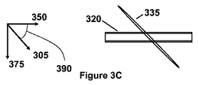
[0056]図3Aは、フローセルを照明する電磁放射のビームの別の斜視図を示す。この図において、ビーム310はビーム伝搬軸315と平行に進行している。フローセル320を流れる粒子及び流体は流れの方向350と平行に移動する。図3Bは、フローセル320の領域の拡大図を示す。粒子340は、軌道355に沿って流れの方向350と平行に移動し、領域365でビーム310と相互作用し、その領域で散乱又は放射された電磁放射を生成する。図3C、3D、及び3Eは、フローセル320及びビーム310の様々な図を示す。図3Cは、ビームの伝搬軸に沿って見たフローセル320及びビームの図を示す。ビームの断面プロファイル335がこの図に示されている。この実施形態では、断面プロファイル335は楕円形状を有する。図3Cは、さらに、この図が流れの方向350、光学収集軸375、及びビーム断面プロファイルの長軸305を示すために1組の軸を示している。角度390は、流れの方向350とビーム断面プロファイルの長軸305との間に形成される。様々な実施形態において、角度390は90°とは異なり、すなわち、流れの方向350とビーム断面プロファイルの長軸305とは非直角である。しかし、実施形態によっては、角度390は90°である。図3Dは、流れの方向に沿って見たフローセル320の図を示す。ビーム310は、フローセル320を照明するビーム伝搬軸315に沿って伝搬する。粒子がビーム310と相互作用することによって生成された散乱又は放射された電磁放射は光学収集軸375に沿って収集される。図3Eは、光学収集軸に沿った図を示す。粒子及び流体は流れの方向350にフローセル320を通って流れる。ビーム310は、フローセル320を照明するビーム伝搬軸315に沿って伝搬する。この実施形態では、フローセル320のわずかな部分しかビーム310によって照明されない。照明される領域は図3Eの破線によって示される。しかし、流体はすべてビームを通って流れる。
[0056] FIG. 3A shows another perspective view of a beam of electromagnetic radiation illuminating the flow cell. In this figure, the
[0057]本発明は、以下の非限定の実施例によってさらに理解することができる。 [0057] The invention can be further understood by the following non-limiting examples.
実施例1:粒子検出器画像及び計数効率
[0058]図4A、4B、及び4Cは、流れの方向とビーム断面プロファイルの長軸との間の様々な角度について粒子検出システムの実施形態の2次元検出器によって検出された画像を示す。これらのグレースケール画像は2次元検出器によって観察された強度を表し、黒色は低い強度であり、白色は高い強度である。これらの画像は図3Eと同様のフローセルの図を表す。これらの画像において、画像の最上部の明るい白色スポットは、ビームがフローセルに入るフローセルの壁とビームが相互作用することによって生成された散乱又は放射された電磁放射を表す。画像の最下部の明るい白色スポットは、ビームがフローセルを出るフローセルの壁とビームが相互作用することによって生成された散乱又は放射された電磁放射を表す。これらの画像において、125nmのサイズを有する粒子が、流れの方向350に沿って流体中で移動しており、ビームは軸315に沿って伝搬している。これらの画像中の差込み図は、ビーム伝搬軸に沿ったフローセルの図を示し、フローセル及び流れの方向350に対するビーム断面プロファイルの長軸305の方位を示す。
Example 1: Particle detector image and counting efficiency
[0058] FIGS. 4A, 4B, and 4C show images detected by the two-dimensional detector of the particle detection system embodiment for various angles between the direction of flow and the long axis of the beam cross-sectional profile. These grayscale images represent the intensity observed by the two-dimensional detector, with black being a low intensity and white being a high intensity. These images represent a flow cell diagram similar to FIG. 3E. In these images, the bright white spot at the top of the image represents scattered or radiated electromagnetic radiation generated by the interaction of the beam with the walls of the flow cell where the beam enters the flow cell. The bright white spot at the bottom of the image represents scattered or radiated electromagnetic radiation generated by the interaction of the beam with the flow cell wall where the beam exits the flow cell. In these images, particles having a size of 125 nm are moving in the fluid along the
[0059]図4Aにおいて、ビーム断面プロファイルの長軸305は流れの方向350に垂直であり、すなわち、角度390は90°である。画像の中心にある明るい白色スポットはフローセルの壁の汚染の結果である。画像の最上部から画像の最下部に移動するかすかな線は、軸315に沿って伝搬するビームとフローセル中の流体が相互作用するによって散乱された電磁放射を表す。図4Aの画像において、周辺よりも明るいかすかなスポットは単一の粒子の検出を示すことができる(画像中の矢印によって示されている)。明るい白色スポットは、恐らく、ビームと相互作用するフローセルの壁にある汚染の結果である。この方位で、これのような汚染によって散乱又は放射された電磁放射は、粒子が移動することができる流れの領域に沿って位置し、それによりこれらの領域からの粒子の検出を不明瞭にする。角度390が90°とは異なる場合、フローセルの壁の汚染は画像の左側又は右側の方に現れ、そのような大きい領域を不明瞭にしないはずである。
[0059] In FIG. 4A, the
[0060]図4Bにおいて、ビーム断面プロファイルの長軸305及び流れの方向350は約45°の角度390を形成する。画像の左側に沿った2つの明るい白色スポットはフローセルの壁の汚染の結果である。以前に述べたように、ビームの断面プロファイルは、今では、45°の角度390であるので、汚染からの散乱又は放射された電磁放射は、もはや流れ領域の主要部分を不明瞭にせず、画像の両側に現れる。画像の最上部から画像の最下部に移動するかすかなグローは、軸315に沿って伝搬するビームとフローセル中の流体が相互作用することによって散乱された電磁放射を表す。図4Bの画像において、周辺よりも明るいいくつかのかすかなスポットは粒子の検出を示すことができる(画像中の矢印によって示された3つの例)。角度390が90°である図4Aの幾何学的構成では、長い矢印によって示された粒子は、恐らく、画像の左側にある最高に明るい汚染スポットにより検出が不明瞭となるであろう。これは、雑音を低減し、検出効率及び感度を向上する際に非直角幾何学的構成の有用な利点を示している。さらに、ビーム断面プロファイルの長軸305が、図4Bのように流れの方向350に非直角である場合、散乱又は放射された放射が2次元検出器上で検出される場所は、フローセル中の散乱又は放射された放射の起点の位置に関連する。例えば、画像の左側の明るい汚染スポットは、差込み図中の要素395によって示されるようにフローセルの一方の側の汚染からのものであるように見え、一方、長い矢印によって示された粒子は、差込み図中の要素340によって示されたフローセルの反対側の近くを移動する粒子からのものであるように見える。
[0060] In FIG. 4B, the
[0061]図4Cにおいて、ビーム断面プロファイルの長軸305は約21°の角度390で流れの方向350に位置合わせされる。画像の最上部から画像の最下部に移動するかすかなグローは、軸315に沿って伝搬するビームとフローセル中の流体が相互作用することによって散乱された電磁放射を表す。図4Cの画像において、周辺よりも明るいいくつかのかすかなスポットは粒子の検出を示している(画像中の矢印によって示された5つの例)。フローセルの壁からの散乱又は放射された電磁放射の分離とは別に、ビーム断面プロファイルの長軸305が流れの方向350に非直角である場合、粒子はビームを通って移動する距離がより長く、それにより、より多く光散乱された粒子及びより小さい粒子を検出することができる。
[0061] In FIG. 4C, the
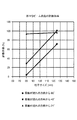
[0062]粒子の計数効率を決定するために、80nm及び125nmのサイズを有するポリスチレンラテックス粒子を、粒子検出システムを通して流すことができた。流れの方向とビーム断面プロファイルの長軸との間の角度は、3つの方向に、すなわち、流れの方向とビーム断面プロファイルの長軸との間の21°の角度、流れの方向とビーム断面プロファイルの長軸との間の45°の角度、及び流れの方向とビーム断面プロファイルの長軸との間の90°の角度に変更された。図5は、流れの方向とビーム断面プロファイルの長軸との間の角度の関数として80nmの粒子の計数効率を例示するデータを示す。図5で分かるように、80nmの粒子の計数効率は、角度が21°から45°、さらに90°に増加するにつれて低下している。図6は、125nmの粒子の計数効率を例示する同様のデータを示す。図6で分かるように、125nmの粒子の計数効率は21°及び45°でほぼ100%であるが、90°の角度で80%未満の計数効率にかなり減少している。図7は、80nm及び125nmのポリスチレンラテックス粒子の計数効率を集約している。 [0062] To determine particle counting efficiency, polystyrene latex particles having sizes of 80 nm and 125 nm could be flowed through the particle detection system. The angle between the direction of flow and the major axis of the beam cross-sectional profile is in three directions, ie the angle of 21 ° between the direction of flow and the major axis of the beam cross-sectional profile, the direction of flow and the beam cross-sectional profile. The angle was changed to 45 ° between the major axis of the beam and 90 ° between the direction of flow and the major axis of the beam cross-sectional profile. FIG. 5 shows data illustrating the counting efficiency of 80 nm particles as a function of the angle between the direction of flow and the long axis of the beam cross-sectional profile. As can be seen in FIG. 5, the counting efficiency of 80 nm particles decreases as the angle increases from 21 ° to 45 ° and further to 90 °. FIG. 6 shows similar data illustrating the counting efficiency of 125 nm particles. As can be seen in FIG. 6, the counting efficiency of the 125 nm particles is almost 100% at 21 ° and 45 °, but is significantly reduced to a counting efficiency of less than 80% at the 90 ° angle. FIG. 7 summarizes the counting efficiency of 80 nm and 125 nm polystyrene latex particles.
実施例2:一体化シールをもつ粒子計数法用細管マウント
[0063]液体粒子カウンタを悩ませてきた1つの問題は、フローセルに試料細管を封着するための化学耐性シールがないことである。この問題を解決する一手法は、細管入口との封止を生成するために、反応しにくく実質的に剛性のポリマー、例えば、80 Shore DのKel−fを含むホルダ又はマウントを使用する。ホルダ又はマウントは、ホルダ又はマウントに一体化される細管の開口のまわりに1つ又は複数の同心シールを含む。これにより、潜在的な漏れ経路の数が減らされ、不適切に取り付けられることがある構成要素が除去され、許容範囲の数値が低減され、より均一なシール圧力が保証される。実施形態では、粒子カウンタ又は粒子検出システムはそのような細管マウントを含む。
Example 2: Capillary mount for particle counting method with integral seal
[0063] One problem that has plagued liquid particle counters is the lack of a chemically resistant seal to seal the sample capillaries to the flow cell. One approach to solving this problem uses a holder or mount that includes a non-reactive and substantially rigid polymer, such as 80 Shore D Kel-f, to create a seal with the capillary inlet. The holder or mount includes one or more concentric seals around a capillary opening integrated into the holder or mount. This reduces the number of potential leak paths, removes components that may be improperly installed, reduces tolerance numbers, and ensures a more uniform seal pressure. In embodiments, the particle counter or particle detection system includes such a capillary mount.
[0064]本発明の画像化ベース粒子カウンタは、例えば、ホルダと一体化する細管開口のまわりに一連の同心シールを生成するように機械加工又は成型によって形成される剛性ポリマー(例えば、80 Shore DのKel−f)を使用する一体化シールを備えた粒子計数用細管マウントを適宜含む。一体化シールを備えた細管マウントを使用するのは、用途によっては、それにより、潜在的な漏れ経路の数が減らされ、不適切に取り付けられることがある構成要素が除去され、許容範囲の数値が低減され、より均一なシール圧力が保証されるので有益である。 [0064] The imaging-based particle counter of the present invention is a rigid polymer (eg, 80 Shore D) formed, for example, by machining or molding to produce a series of concentric seals around a capillary opening that is integral with the holder. Optionally includes a particle counting capillary mount with an integral seal using Kel-f). Using capillary mounts with integral seals, depending on the application, reduces the number of potential leak paths, eliminates components that may be improperly installed, and is an acceptable numerical value. Is beneficial, and a more uniform sealing pressure is ensured.
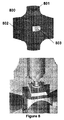
[0065]図8は、例示的な細管マウント800の斜視図を示す。細管マウント800は、細管との封止を生成するための複数の封止領域801を含む。細管マウント800は、フローセルと、フローセルへのレーザビームの入りと出を可能にするための複数のウィンドウ領域802とをさらに含む。追加のウィンドウ領域803は散乱光を検出器に送出するために含まれる。いくつかの実施形態では、細管マウント800は単一構造体であり、すなわち、1つ又は複数の細管との封止を形成するための単一片の材料を含む。
[0065] FIG. 8 shows a perspective view of an
実施例3:非直角粒子検出器の自動合焦
[0066]粒子走行時間、適用区域を最大化し、被写界深度を最小にするために、粒子検出器中のレーザ経路は細管セルに対して傾けられる。一実施形態では、ビーム断面プロファイルの長軸は、細管セル内の流れの方向に非直角に向けられる。別の実施形態では、ビーム伝搬軸は細管セル内の流れの方向に非直角に向けられる。例えば、これらの軸は69°又は21°の相対角度で向けることができる。流れ中の粒子から散乱された又は流れ中の粒子によって放射された放射を収集すること、及び適切な合焦を保証することのために、検出器及び細管は、任意のセンサ画像化光学系、例えば上述のような光学系に対して傾けられる。本発明の画像化ベース粒子カウンタは、粒子スポットサイズ若しくはレーザビーム構造のいずれか又は両方の組合せを使用する自動合焦を適宜含む。
Example 3: Automatic focusing of a non-right angle particle detector
[0066] The laser path in the particle detector is tilted with respect to the capillary cell to maximize particle transit time, application area, and minimize depth of field. In one embodiment, the long axis of the beam cross-sectional profile is oriented non-perpendicular to the direction of flow in the capillary cell. In another embodiment, the beam propagation axis is oriented non-perpendicular to the direction of flow in the capillary cell. For example, these axes can be oriented at a relative angle of 69 ° or 21 °. In order to collect the radiation scattered from or emitted by the particles in the flow, and to ensure proper focusing, the detector and tubules are optional sensor imaging optics, For example, it is tilted with respect to the optical system as described above. The imaging-based particle counter of the present invention optionally includes automatic focusing using either particle spot size or laser beam structure or a combination of both.
[0067]画像化光学系の光軸に沿った検出器の場所は、散乱又は放射された放射の最良の合焦を達成するように移動によって調整することができるが、さらに、移動の範囲の全体にわたって検出器の同じ場所に画像を保持しなければならない。これを達成する方法には、画像化光学系の光軸に対して固定角で検出器を取り付けるステップと、合焦するために画像化軸に沿って検出器を移動するステップとが含まれる。一実施形態では、検出器は、検出器を光軸に沿って移動するために光軸に位置合わせされた直線レールシステムに取り付けられる。特定の実施形態では、ばねを取り付けて、画像化光学系に予圧をかけて傾いた面の一方の側に押し付け、移動ステップモーターの精度を向上させ(例えば5倍以上)、ステップモーターのステップ当たりの直線運動のより小さい増加(例えば2μm以下)を可能にする。一実施形態では、粒子カウンタ又は粒子検出システムは自動合焦システムを含む。 [0067] The location of the detector along the optical axis of the imaging optics can be adjusted by movement to achieve the best focus of the scattered or emitted radiation, but further The image must be kept at the same location on the detector throughout. Methods for accomplishing this include attaching the detector at a fixed angle with respect to the optical axis of the imaging optics and moving the detector along the imaging axis to focus. In one embodiment, the detector is attached to a linear rail system aligned with the optical axis to move the detector along the optical axis. In certain embodiments, a spring is attached and pressed against one side of the tilted surface with pre-loading on the imaging optics to improve the accuracy of the moving step motor (e.g., more than 5 times) and per step of the step motor. Allows a smaller increase (eg 2 μm or less) in linear motion. In one embodiment, the particle counter or particle detection system includes an autofocus system.
[0068]図9は特定の自動合焦システムの実施形態900を示す。細管セルは細管マウント901に取り付けられ、検出器902はブロック903内に収容された画像化光学系に対してある角度で取り付けられる。直線レールシステム904は、ブロック903内に収容された画像化光学系の光軸に沿った検出器902の移動のために、検出器902及びステップモーター905に取り付けられる。
[0068] FIG. 9 shows an
実施例3:検出器アレイ処理
[0069]実施形態では、電磁放射は、粒子が粒子検出システムの電磁放射のビームと相互作用することによって散乱又は放射され、2次元検出器に達する散乱又は放射された電磁放射は検出され、それによって、散乱又は放射された電磁放射の強度に対応する複数の出力信号を生成する。これらの出力信号をさらに処理及び/又は分析して、粒子の特性を決定することができる。
Example 3: Detector array processing
[0069] In an embodiment, electromagnetic radiation is scattered or emitted by particles interacting with a beam of electromagnetic radiation of a particle detection system, and scattered or emitted electromagnetic radiation reaching a two-dimensional detector is detected, and Produces a plurality of output signals corresponding to the intensity of the scattered or radiated electromagnetic radiation. These output signals can be further processed and / or analyzed to determine the characteristics of the particles.
[0070]いくつかの実施形態では、2次元検出器のすべての要素からの出力信号が記録されるか、又はさらなる分析のためにプロセッサに送出される。しかし、他の実施形態では、2次元検出器の要素のサブアレイ(すなわち一部だけ)からの出力信号が記録されるか、又はさらなる分析のためにプロセッサに送出される。このように、粒子の特性の検出又は感知に使用するために2次元検出器のサブセットを選択することが可能である。特定の実施形態では、サブアレイの出力信号の一部だけが粒子の特性を決定する際に利用される。注目するそのような領域は、例えば、検出された粒子のより良好なサイズ解像度の生成及び/又は検出にかけられる試料容積の増大の防止に有用である。 [0070] In some embodiments, output signals from all elements of the two-dimensional detector are recorded or sent to a processor for further analysis. However, in other embodiments, the output signal from a sub-array (ie, only a portion) of the elements of the two-dimensional detector is recorded or sent to the processor for further analysis. In this way, it is possible to select a subset of a two-dimensional detector for use in detecting or sensing particle properties. In certain embodiments, only a portion of the subarray output signal is utilized in determining particle characteristics. Such regions of interest are useful, for example, in generating a better size resolution of the detected particles and / or preventing an increase in sample volume subjected to detection.
[0071]例えば、2次元検出器全体は、粒子検出システムのフローセル全体を画像化することができる。特定のサブアレイは、フローセルの画像化領域、例えば、電磁放射のビームによって照明されたフローセルの領域の出力信号に対応することができる。別の例として、サブアレイは、電磁放射のビームによって照明されたフローセルの画像化領域の出力信号に対応するが、フローセルの壁を排除することができる。注目する領域は、例えば、電磁放射のビームの中心によって照明されたフローセルの画像化領域及び/又は電磁放射のビームの強度が実質的に均一である場所に対応する出力信号を含むことができる。 [0071] For example, the entire two-dimensional detector can image the entire flow cell of the particle detection system. A particular sub-array can correspond to the output signal of the flow cell imaging region, for example the region of the flow cell illuminated by a beam of electromagnetic radiation. As another example, the subarray corresponds to the output signal of the imaging region of the flow cell illuminated by a beam of electromagnetic radiation, but can eliminate the flow cell walls. The region of interest may include, for example, an imaging region of the flow cell illuminated by the center of the beam of electromagnetic radiation and / or an output signal corresponding to a location where the intensity of the beam of electromagnetic radiation is substantially uniform.
[参照による援用及び変形に関する説明]
[0072]本出願の全体にわたるすべての参考文献、例えば、発行済み特許若しくは登録特許又は均等物を含む特許文献、特許出願公開、及び非特許文献若しくは他の資料は、あたかも各参照が本出願の開示と少なくとも部分的に矛盾しない範囲で参照により個々に組み込まれる(例えば、部分的に矛盾する参照は、参照の部分的に矛盾する部分を除いて参照により組み込まれる)ように、参照によりそれらの全体が本明細書に組み込まれる。それぞれ2007年12月4日、2007年12月4日、及び2008年10月22日に出願された米国特許仮出願第61/005,336号、第60/992,192号、及び第61/107,397号は、参照によりそれらの全体が本明細書に組み込まれる。代理人整理番号No.171−07を有し、2008年12月2日に出願された、発明者のMitchell、Sandberg、Sehler、Williamson、及びRiceによる「Two−Dimensional Optical Imaging Methods and Systems for Particle Detection」という名称の米国非仮出願は参照によりその全体が本明細に組み込まれる。
[Explanation on Incorporation and Modification by Reference]
[0072] All references throughout this application, for example, patent documents including issued patents or registered patents or equivalents, patent application publications, and non-patent documents or other materials, are as if each reference is Those references are incorporated by reference so that they are individually incorporated by reference to the extent that they are at least partially inconsistent with the disclosure (eg, partially inconsistent references are incorporated by reference except for partially inconsistent parts of the reference). The entirety is incorporated herein. U.S. Provisional Application Nos. 61 / 005,336, 60 / 992,192, and 61 / filed on Dec. 4, 2007, Dec. 4, 2007, and Oct. 22, 2008, respectively. Nos. 107,397 are hereby incorporated by reference in their entirety. Agent reference number No. "The Two-Dimensional Optical Imaging Methods and Part of the United States" by Inventors Mitchell, Sandberg, Sehler, Williamson, and Rice, filed December 2, 2008. The provisional application is incorporated herein by reference in its entirety.
[0073]明細書で述べられたすべての特許及び刊行物は本発明が関係する当業者の技術レベルを示している。本明細書に引用された参考文献は、いくつかの場合それらの出願日の時点での最新技術を示すために参照によりそれらの全体が本明細書に組み込まれ、この情報は、必要であれば、先行技術である特定の実施形態を除外するために(例えば、放棄するために)本明細書で使用することができるものである。例えば、化合物が特許請求される場合、本明細書で開示された参考文献に(特に参照された特許文献に)開示されているいくつかの化合物を含む先行技術で既知の化合物は、特許請求の範囲に含まれるものではないことが理解されるべきである。 [0073] All patents and publications mentioned in the specification are indicative of the levels of skill of those skilled in the art to which this invention pertains. References cited herein are hereby incorporated by reference in their entirety to indicate state of the art as of their filing date, and this information is , Which can be used herein to exclude (eg, to abandon) certain embodiments that are prior art. For example, if a compound is claimed, compounds known in the prior art, including some compounds disclosed in the references disclosed herein (especially in the referenced patent documents), are claimed. It should be understood that it is not included in the scope.
[0074]置換基の群が本明細書で開示される場合、群のメンバーの任意の異性体及び鏡像異性体を含むそれらの群及びすべての亜群のすべての個別のメンバー、並びに置換基を使用して形成することができる化合物の種類は別々に開示されることが理解されよう。化合物が特許請求される場合、本明細書で開示された参考文献に開示されている化合物を含む当技術分野で既知の化合物は含まれるものではないことが理解されるべきである。マーカッシュ群又は他の群分けが本明細書で使用される場合、群の個々のメンバーのすべて、及び群の可能な組合せ及び部分組合せ(subcombination)のすべては本開示に個別に含まれるものである。 [0074] Where groups of substituents are disclosed herein, all individual members of those groups and all subgroups, including any isomers and enantiomers of the members of the group, and substituents It will be appreciated that the types of compounds that can be formed using are disclosed separately. When compounds are claimed, it should be understood that compounds known in the art, including those disclosed in the references disclosed herein, are not included. When a Markush group or other grouping is used herein, all of the individual members of the group, and all possible combinations and subcombinations of the group, are individually included in the disclosure. .
[0075]記載又は例示された成分のあらゆる調合物又は組合せは、特に明言されない限り本発明を実施するために使用することができる。当業者が同じ化合物を異なるように命名することができることが知られている場合、化合物の特定の名称は例示的なものである。化合物の特定の異性体又は鏡像異性体が例えば化学式又は化学名で指定されていないような化合物が本明細書で説明されている場合、その説明は個別に又は任意の組合せで記載された化合物の各異性体及び鏡像異性体を含むものである。方法、デバイス要素、出発原料、及び詳細に例示されたもの以外の合成方法は、必要以上の実験に頼ることなく本発明の実行において使用することができることが当業者には理解されよう。任意のそのような方法、デバイス要素、出発原料、及び合成方法の当技術分野で既知の機能的均等物はすべて本発明に含まれるものである。範囲、例えば温度範囲、時間範囲、又は組成範囲が明細書に与えられている場合はいつでも、すべての中間範囲及び部分範囲並びに所与の範囲に含まれるすべての個々の値は本開示に含まれるものである。 [0075] Any formulation or combination of ingredients described or exemplified can be used to practice the invention, unless expressly stated otherwise. Where it is known that one skilled in the art can name the same compound differently, the specific names of the compounds are exemplary. Where a compound is described herein in which a particular isomer or enantiomer of the compound is not specified by, for example, a chemical formula or chemical name, the description is for the compounds described individually or in any combination. Each isomer and enantiomer are included. Those skilled in the art will appreciate that methods, device elements, starting materials, and synthetic methods other than those specifically illustrated can be used in the practice of the present invention without undue experimentation. Any such methods, device elements, starting materials, and functional equivalents known in the art of synthetic methods are intended to be included in the present invention. Whenever a range, such as a temperature range, a time range, or a composition range is given in the specification, all intermediate and subranges and all individual values included in a given range are included in this disclosure. Is.
[0076]本明細書で使用される「含む(comprising)」は、「含む(including)」、「含む(containing)」、又は「によって特徴づけられる(characterized by)」と同義であり、包括的(inclusive)又は非限定的(open−ended)であり、追加要素、記載されなかった要素、又は方法ステップを排除しない。本明細書で使用される「からなる(consisting of)」は請求項の要素に指定されていないいかなる要素、ステップ、又は成分も排除する。本明細書で使用される「本質的に〜からなる(consisting essentially of)」は、請求項の基本的及び新規な特徴に実質的に影響を与えない材料又はステップを排除しない。特に組成物の成分の説明又はデバイスの要素の説明における「含む(comprising)」という用語の本明細書でのいかなる詳述も記載された成分又は要素から本質的になる、及び記載された成分又は要素からなるこれらの組成物及び方法を包含することが理解されよう。本明細書で例示として説明された本発明は、本明細書で詳細には開示されていないいかなる1つ又は複数の要素、1つ又は複数の限定がない状態でも適切に実施することができる。 [0076] As used herein, "comprising" is synonymous with "including", "containing", or "characterized by" and is comprehensive (Inclusive) or open-ended and does not exclude additional elements, elements not described, or method steps. As used herein, “consisting of” excludes any element, step, or ingredient not specified in the claim element. As used herein, “consisting essentially of” does not exclude materials or steps that do not materially affect the basic and novel characteristics of the claim. In particular, any detailed description herein of the term “comprising” in the description of the components of the composition or in the description of the elements of the device consists essentially of the described component or element, and the described component or It will be understood to encompass these compositions and methods of elements. The invention described herein by way of example can be suitably practiced without any one or more elements, one or more limitations, not disclosed in detail herein.
[0077]使用された用語及び表現は制限のためではなく説明のための用語として使用されており、そのような用語及び表現の使用において図示及び説明された特徴又はそれらの一部のいかなる均等物も排除することを意図していないが、本発明の特許請求の範囲内で様々な改変が可能であることが認識されよう。したがって、本発明が好ましい実施形態及び任意選択の特徴によって詳細に開示されたが、本明細書で開示された概念の改変及び変形を当業者は用いることができること、並びにそのような改変及び変形は添付の特許請求の範囲によって規定されるような本発明の範囲内にあると見なされることが理解されるべきである。 [0077] The terms and expressions used are used as terms for description, not for limitation, and any equivalents of the features illustrated and described in the use of such terms and expressions, or portions thereof. Although not intended to be excluded, it will be appreciated that various modifications can be made within the scope of the appended claims. Thus, although the present invention has been disclosed in detail with preferred embodiments and optional features, those skilled in the art can use modifications and variations of the concepts disclosed herein, and such modifications and variations are not It is to be understood that the invention is deemed to be within the scope of the invention as defined by the appended claims.
Claims (33)
長軸及び短軸を有する断面プロファイルを有する電磁放射のビームを生成するための供給源であり、前記供給源が前記ビームを前記フローセル経由で導くように位置決めされ、前記長軸と前記流れの方向との間の角度が非直角であり、前記流体内に含まれる粒子が前記ビームと相互作用し、それによって散乱又は放射された電磁放射を生成する、供給源と、
前記散乱又は放射された電磁放射の少なくとも一部を受け取るように前記フローセルと光通信して位置決めされた2次元検出器と、
前記散乱又は放射された電磁放射を前記2次元検出器上に収集及び導くための光学系と、
を備え、
前記光学系は、前記長軸に非直角に位置決めされた光軸を有し、
前記2次元検出器は、前記光学系の前記光軸に非直角に位置決めされている粒子検出システム。 A flow cell containing a fluid, wherein the fluid flows through the flow cell in a predetermined flow direction;
A source for generating a beam of electromagnetic radiation having a cross-sectional profile having a major axis and a minor axis, wherein the source is positioned to direct the beam through the flow cell, the major axis and the direction of the flow A source that is non-perpendicular between and particles contained within the fluid interact with the beam, thereby generating scattered or radiated electromagnetic radiation;
A two-dimensional detector positioned in optical communication with the flow cell to receive at least a portion of the scattered or emitted electromagnetic radiation ;
An optical system for collecting and directing the scattered or radiated electromagnetic radiation onto the two-dimensional detector;
Equipped with a,
The optical system has an optical axis positioned non-perpendicular to the major axis;
The two-dimensional detector is a particle detection system that is positioned non-perpendicular to the optical axis of the optical system.
所定の流れの方向を有する流体中の粒子を供給するステップと、
長軸及び短軸を有する断面プロファイルを有する電磁放射のビームを前記流体経由で通過させるステップであり、前記長軸と前記流れの方向との間の角度が非直角であり、前記粒子が前記ビームと相互作用し、それによって散乱又は放射された電磁放射を生成する、ステップと、
前記散乱又は放射された電磁放射を、光学系を用いて2次元検出器上に収集又は導くステップであって、前記光学系は前記長軸に非直角に位置決めされた光軸を有する、ステップと、
前記散乱又は放射された電磁放射の少なくとも一部を、前記光学系の前記光軸に非直角に位置決めされた2次元検出器を用いて検出し、それによって前記粒子を検出するステップと、
を含む方法。 A method for detecting particles comprising:
Providing particles in a fluid having a predetermined flow direction;
Passing a beam of electromagnetic radiation having a cross-sectional profile having a major axis and a minor axis through the fluid, wherein an angle between the major axis and the direction of flow is non-perpendicular, and the particles are the beam Interacting with and thereby generating scattered or radiated electromagnetic radiation; and
Collecting or directing the scattered or radiated electromagnetic radiation onto a two-dimensional detector using an optical system, the optical system having an optical axis positioned non-perpendicular to the major axis; ,
Detecting at least a portion of the scattered or emitted electromagnetic radiation using a two-dimensional detector positioned non-perpendicular to the optical axis of the optical system , thereby detecting the particles ;
Including methods.
流れの方向に流れる流体内に浮遊する粒子を供給するステップと、
電磁放射のビームを前記流体経由で通過させるステップであり、前記ビームが長軸及び短軸を有する断面プロファイルを有し、前記長軸と前記流れの方向との間の角度が非直角であり、前記粒子が前記ビームと相互作用し、それによって散乱又は放射された電磁放射を生成する、ステップと、
前記散乱又は放射された電磁放射を、光学系を用いて2次元検出器上に収集又は導くステップであって、前記光学系は前記長軸に非直角に位置決めされた光軸を有し、前記2次元検出器は、前記光学系の前記光軸に非直角に位置決めされた、ステップと、
前記散乱又は放射された電磁放射の少なくとも一部を前記2次元検出器を用いて検出し、それによって、前記散乱又は放射された電磁放射を前記ビームの伝搬軸と平行な第1の方向に及び前記ビームの前記断面プロファイルの前記長軸と平行な第2の方向に空間的に分離する、ステップとを含む方法。 A method of spatially separating the interaction of particles with a beam of electromagnetic radiation,
Supplying suspended particles in a fluid flowing in the direction of flow;
Passing a beam of electromagnetic radiation through the fluid, wherein the beam has a cross-sectional profile having a major axis and a minor axis, and the angle between the major axis and the direction of flow is non-perpendicular; The particles interact with the beam, thereby generating scattered or emitted electromagnetic radiation;
Collecting or directing the scattered or radiated electromagnetic radiation onto a two-dimensional detector using an optical system, the optical system having an optical axis positioned non-perpendicular to the major axis; A two-dimensional detector positioned non-perpendicular to the optical axis of the optical system;
Wherein at least a portion of the scattered or emitted electromagnetic radiation detected by using the two-dimensional detector, thereby Oyobi the scattered or emitted electromagnetic radiation in a first direction parallel to the propagation axis of the beam Spatially separating in a second direction parallel to the major axis of the cross-sectional profile of the beam.
フローセルを通って流れの方向に流れる流体内に浮遊する粒子を供給するステップと、
電磁放射のビームを前記流体経由で通過させるステップであり、前記ビームが長軸及び短軸を有する断面プロファイルを有し、前記長軸と前記流れの方向との間の角度が非直角であり、前記粒子が前記ビームと相互作用し、それによって散乱又は放射された電磁放射を生成する、ステップと、
前記散乱又は放射された電磁放射を、光学系を用いて2次元検出器上に収集又は導くステップであって、前記光学系は前記長軸に非直角に位置決めされた光軸を有し、前記2次元検出器は、前記光学系の前記光軸に非直角に位置決めされた、ステップと、
前記散乱又は放射された電磁放射の少なくとも一部を前記2次元検出器上に画像化するステップと、
前記2次元検出器上に画像化された前記散乱又は放射された電磁放射の強度を決定するステップと、
前記2次元検出器上に画像化された前記散乱又は放射された電磁放射の前記強度を1つ又は複数の閾値基準値と比較し、それによって前記粒子のサイズを決定するステップと
を含む方法。 A method for sizing particles comprising:
Supplying suspended particles in a fluid flowing in the direction of flow through the flow cell;
Passing a beam of electromagnetic radiation through the fluid, wherein the beam has a cross-sectional profile having a major axis and a minor axis, and the angle between the major axis and the direction of flow is non-perpendicular; The particles interact with the beam, thereby generating scattered or emitted electromagnetic radiation;
Collecting or directing the scattered or radiated electromagnetic radiation onto a two-dimensional detector using an optical system, the optical system having an optical axis positioned non-perpendicular to the major axis; A two-dimensional detector positioned non-perpendicular to the optical axis of the optical system;
A step of imaging at least a portion of said scattered or emitted electromagnetic radiation onto the two-dimensional detector,
A method to decide the imaged said scattered or emitted intensity of the electromagnetic radiation on the two-dimensional detector,
Comparing the intensity of the scattered or emitted electromagnetic radiation imaged on the two-dimensional detector with one or more threshold reference values, thereby determining the size of the particles.
Applications Claiming Priority (7)
| Application Number | Priority Date | Filing Date | Title |
|---|---|---|---|
| US533607P | 2007-12-04 | 2007-12-04 | |
| US99219207P | 2007-12-04 | 2007-12-04 | |
| US61/005,336 | 2007-12-04 | ||
| US60/992,192 | 2007-12-04 | ||
| US10739708P | 2008-10-22 | 2008-10-22 | |
| US61/107,397 | 2008-10-22 | ||
| PCT/US2008/085236 WO2009073649A1 (en) | 2007-12-04 | 2008-12-02 | Non-orthogonal particle detection systems and methods |
Publications (3)
| Publication Number | Publication Date |
|---|---|
| JP2011505577A JP2011505577A (en) | 2011-02-24 |
| JP2011505577A5 JP2011505577A5 (en) | 2011-12-22 |
| JP5324598B2 true JP5324598B2 (en) | 2013-10-23 |
Family
ID=40718129
Family Applications (3)
| Application Number | Title | Priority Date | Filing Date |
|---|---|---|---|
| JP2010537010A Active JP5324598B2 (en) | 2007-12-04 | 2008-12-02 | Non-right angle particle detection system and method |
| JP2010537012A Active JP5478501B2 (en) | 2007-12-04 | 2008-12-02 | Two-dimensional optical imaging method and system for particle detection |
| JP2012261043A Active JP5610167B2 (en) | 2007-12-04 | 2012-11-29 | Two-dimensional optical imaging method and system for particle detection |
Family Applications After (2)
| Application Number | Title | Priority Date | Filing Date |
|---|---|---|---|
| JP2010537012A Active JP5478501B2 (en) | 2007-12-04 | 2008-12-02 | Two-dimensional optical imaging method and system for particle detection |
| JP2012261043A Active JP5610167B2 (en) | 2007-12-04 | 2012-11-29 | Two-dimensional optical imaging method and system for particle detection |
Country Status (5)
| Country | Link |
|---|---|
| US (5) | US7916293B2 (en) |
| EP (2) | EP2232229B1 (en) |
| JP (3) | JP5324598B2 (en) |
| CN (2) | CN101925809B (en) |
| WO (2) | WO2009073652A1 (en) |
Families Citing this family (114)
| Publication number | Priority date | Publication date | Assignee | Title |
|---|---|---|---|---|
| AU2003902319A0 (en) | 2003-05-14 | 2003-05-29 | Garrett Thermal Systems Limited | Laser video detector |
| CN102539384B (en) * | 2004-11-12 | 2016-08-03 | 爱克斯崔里斯科技有限公司 | Particle detector, System and method for |
| US8021469B2 (en) * | 2005-07-14 | 2011-09-20 | Access Business Group International Llc | Control methods for an air treatment system |
| WO2008010870A2 (en) | 2006-05-18 | 2008-01-24 | Massachusetts Institute Of Technology | Method and apparatus for measuring a position of a particle in a flow |
| CA3103407A1 (en) | 2007-11-15 | 2009-05-22 | Garrett Thermal Systems Limited | Particle detection |
| US7916293B2 (en) * | 2007-12-04 | 2011-03-29 | Particle Measuring Systems, Inc. | Non-orthogonal particle detection systems and methods |
| US7920261B2 (en) * | 2008-02-11 | 2011-04-05 | Massachusetts Institute Of Technology | Method and apparatus for detecting and discriminating particles in a fluid |
| ITFI20080095A1 (en) * | 2008-05-15 | 2009-11-16 | Oglio Giorgio Dall | METHOD AND COMPENSATION DEVICE FOR SCATTERING LIGHT SIGNALS GENERATED BY INTERACTION OF LIGHT WITH PARTICLES OR BIOLOGICAL CELLS IN MOTION IN FLUID CURRENT AS IN FLOW CITOMETRY. |
| JP5574250B2 (en) | 2009-08-24 | 2014-08-20 | パーティクル・メージャーリング・システムズ・インコーポレーテッド | Particle sensor whose flow rate is monitored |
| DE102010005962B4 (en) * | 2010-01-21 | 2012-01-26 | Alv-Laser Vertriebsgesellschaft Mbh | Method for determining the static and / or dynamic light scattering |
| KR101675112B1 (en) * | 2010-01-21 | 2016-11-22 | 삼성전자주식회사 | Method of extractig depth information and optical apparatus employing the method |
| WO2011097032A1 (en) | 2010-02-05 | 2011-08-11 | Cytonome/St, Llc | Multiple flow channel particle analysis system |
| EP2531873A4 (en) | 2010-02-05 | 2017-01-25 | Halliburton Energy Services, Inc. | Compensated optical detection apparatus, systems, and methods |
| US9231890B2 (en) | 2010-06-08 | 2016-01-05 | Brocade Communications Systems, Inc. | Traffic management for virtual cluster switching |
| US9274042B2 (en) * | 2010-05-07 | 2016-03-01 | Stc.Unm | Spatially correlated light collection from multiple sample streams excited with a line focused light source |
| WO2011156713A1 (en) | 2010-06-11 | 2011-12-15 | Vanderbilt University | Multiplexed interferometric detection system and method |
| DE102010024964B4 (en) * | 2010-06-24 | 2012-01-26 | Siemens Aktiengesellschaft | Cell monitoring by means of scattered light measurement |
| DK2469264T3 (en) * | 2010-12-21 | 2016-10-03 | Grundfos Management As | Monitoring system |
| CN102288530B (en) * | 2010-12-29 | 2014-05-14 | 天津炜辐医疗科技有限公司 | Time delay integral imaging system for measuring diffraction image of moving particle |
| DE102011000099A1 (en) * | 2011-01-11 | 2012-07-12 | Universität Duisburg-Essen | Analyzer for, e.g. smoke detector, has analysis unit that analyzes aerosol filled analysis portion transverse to illumination direction, where scattering plane spans illumination direction transversely to aerosol flow direction |
| US9562853B2 (en) | 2011-02-22 | 2017-02-07 | Vanderbilt University | Nonaqueous backscattering interferometric methods |
| US8670124B2 (en) * | 2012-01-31 | 2014-03-11 | Nokia Corporation | Apparatus and method for converting sensor input signals into digital output signals |
| WO2013177289A1 (en) | 2012-05-23 | 2013-11-28 | Brocade Communications Systems, Inc. | Layer-3 overlay gateways |
| US10132736B2 (en) | 2012-05-24 | 2018-11-20 | Abbvie Inc. | Methods for inspection of protein particles in a liquid beneficial agent |
| KR101411428B1 (en) * | 2012-07-12 | 2014-06-24 | 한국과학기술원 | Condensing type portable fluorescence detection system |
| US20140080223A1 (en) * | 2012-09-14 | 2014-03-20 | Halliburton Energy Services, Inc. | Systems and Methods for Inspecting and Monitoring a Pipeline |
| CN103728236B (en) | 2012-10-12 | 2016-01-20 | 厦门福流生物科技有限公司 | A kind of method detecting nano particle |
| US9638622B2 (en) * | 2012-12-21 | 2017-05-02 | Sony Corporation | Particle detection apparatus and particle detection method |
| US9070180B2 (en) * | 2013-02-21 | 2015-06-30 | Applied Materials Israel, Ltd. | Method, system, and computer program product for detection of defects based on multiple references |
| US10190960B2 (en) | 2013-03-14 | 2019-01-29 | Cytonome/St, Llc | Micro-lens systems for particle processing systems |
| US9677990B2 (en) | 2014-04-30 | 2017-06-13 | Particles Plus, Inc. | Particle counter with advanced features |
| US10352844B2 (en) | 2013-03-15 | 2019-07-16 | Particles Plus, Inc. | Multiple particle sensors in a particle counter |
| US10983040B2 (en) | 2013-03-15 | 2021-04-20 | Particles Plus, Inc. | Particle counter with integrated bootloader |
| US9401818B2 (en) | 2013-03-15 | 2016-07-26 | Brocade Communications Systems, Inc. | Scalable gateways for a fabric switch |
| US11579072B2 (en) | 2013-03-15 | 2023-02-14 | Particles Plus, Inc. | Personal air quality monitoring system |
| US10701287B1 (en) * | 2013-05-23 | 2020-06-30 | Rockwell Collins, Inc. | Passive clear air turbulence detection system and method |
| CA2911407C (en) * | 2013-06-03 | 2022-12-13 | Xtralis Technologies Ltd | Particle detection system and related methods |
| US9025863B2 (en) * | 2013-06-27 | 2015-05-05 | Intel Corporation | Depth camera system with machine learning for recognition of patches within a structured light pattern |
| US10126220B2 (en) | 2013-07-22 | 2018-11-13 | National Oilwell Varco, L.P. | Systems and methods for determining specific gravity and minerological properties of a particle |
| ITRM20130128U1 (en) | 2013-07-23 | 2015-01-24 | Particle Measuring Systems S R L | DEVICE FOR MICROBIAL AIR SAMPLING |
| EP2860513B1 (en) * | 2013-10-08 | 2018-04-25 | Anton Paar GmbH | Apparatus and method for analyzing a sample which compensate for refraction index related distortions |
| WO2015069566A1 (en) | 2013-11-05 | 2015-05-14 | Arizona Board Of Regents For And On Behalf Of Arizona State University | Adaptive detection sensor array and method of providing and using the same |
| US9523771B2 (en) * | 2014-01-13 | 2016-12-20 | Facebook, Inc. | Sub-resolution optical detection |
| WO2015138695A2 (en) | 2014-03-14 | 2015-09-17 | Particle Measuring Systems, Inc. | Filter and blower geometry for particle sampler |
| US9810558B2 (en) | 2014-03-14 | 2017-11-07 | Particle Measuring Systems, Inc. | Pressure-based airflow sensing in particle impactor systems |
| US10581758B2 (en) | 2014-03-19 | 2020-03-03 | Avago Technologies International Sales Pte. Limited | Distributed hot standby links for vLAG |
| JP6316064B2 (en) * | 2014-03-31 | 2018-04-25 | 株式会社日立ハイテクサイエンス | ICP emission spectrometer |
| JP6546933B2 (en) * | 2014-04-17 | 2019-07-17 | ガタン インコーポレイテッドGatan,Inc. | Hybrid energy converter |
| CN106662773B (en) * | 2014-06-26 | 2021-08-06 | 瑞尔D 斯帕克有限责任公司 | Directional peep-proof display |
| CN104142289A (en) * | 2014-07-24 | 2014-11-12 | 北京大学 | Online monitoring system for atmospheric aerosol |
| JP6282969B2 (en) * | 2014-10-31 | 2018-02-21 | 日本光電工業株式会社 | Flow analysis apparatus, flow cytometer, and flow analysis method |
| US9696265B2 (en) * | 2014-11-04 | 2017-07-04 | Exnodes Inc. | Computational wafer inspection filter design |
| KR102409471B1 (en) * | 2014-12-22 | 2022-06-16 | 가부시키가이샤 호리바 에스텍 | Fluid heater |
| EP3037804A1 (en) * | 2014-12-22 | 2016-06-29 | Grundfos Holding A/S | Method for quantitative and qualitative detection of particles in liquid |
| FR3031180A1 (en) | 2014-12-30 | 2016-07-01 | Commissariat Energie Atomique | METHOD AND DEVICE FOR CONTROLLING THE POSITION OF A TRANSPARENT PARTICLE BY A PILE OF HOLOGRAPHIC IMAGES |
| EP3247988A4 (en) | 2015-01-23 | 2018-12-19 | Vanderbilt University | A robust interferometer and methods of using same |
| CA2977481C (en) | 2015-02-24 | 2021-02-02 | The University Of Tokyo | Dynamic high-speed high-sensitivity imaging device and imaging method |
| US10038592B2 (en) | 2015-03-17 | 2018-07-31 | Brocade Communications Systems LLC | Identifier assignment to a new switch in a switch group |
| KR102436123B1 (en) * | 2015-04-02 | 2022-08-24 | 파티클 머슈어링 시스템즈, 인크. | Laser Noise Detection and Mitigation in Particle Counting Instruments |
| EP3088863A1 (en) * | 2015-05-01 | 2016-11-02 | Malvern Instruments Limited | Improvements relating to particle characterisation |
| AT516759B1 (en) * | 2015-05-12 | 2016-08-15 | Avl List Gmbh | Apparatus and method for determining the number of solid particles in a fluid stream |
| US9476818B1 (en) * | 2015-09-23 | 2016-10-25 | Raytheon Company | Method and apparatus for high sensitivity particulate detection in infrared detector assemblies |
| CN114062231A (en) | 2015-10-28 | 2022-02-18 | 国立大学法人东京大学 | Analysis device |
| CN105547945A (en) * | 2016-01-14 | 2016-05-04 | 天津大学 | Discriminating method for particles in interference particle imaging system sampling area |
| WO2017132483A1 (en) | 2016-01-29 | 2017-08-03 | Vanderbilt University | Free-solution response function interferometry |
| US9857283B1 (en) * | 2016-07-01 | 2018-01-02 | MANTA Instruments, Inc. | Method for calibrating investigated volume for light sheet based nanoparticle tracking and counting apparatus |
| EP4050322A1 (en) * | 2016-08-04 | 2022-08-31 | Malvern Panalytical Limited | Method of characterising particles suspended in a fluid dispersant by light diffraction, processor or instrument and machine-readable, non-transient storage medium |
| US9933350B2 (en) | 2016-08-16 | 2018-04-03 | International Business Machines Corporation | Atmospheric particle counting |
| DK3532865T3 (en) * | 2016-10-31 | 2021-03-08 | Faunaphotonics Agriculture & Env A/S | OPTICAL REMOTE REGISTRATION SYSTEM FOR DETECTING AIR AND WATER FAUNA |
| DE102017201252A1 (en) * | 2017-01-26 | 2018-07-26 | Universität Ulm | Method and device for the examination of cells |
| JP7058271B2 (en) * | 2017-07-26 | 2022-04-21 | 浜松ホトニクス株式会社 | Sample observation device and sample observation method |
| AU2018315048B2 (en) * | 2017-08-10 | 2024-02-15 | Commonwealth Scientific And Industrial Research Organisation | Device and method for monitoring material flow parameters along a passage |
| US11380438B2 (en) | 2017-09-27 | 2022-07-05 | Honeywell International Inc. | Respiration-vocalization data collection system for air quality determination |
| JP7326256B2 (en) | 2017-10-26 | 2023-08-15 | パーティクル・メージャーリング・システムズ・インコーポレーテッド | Particle counting system and method |
| CN108169086A (en) * | 2017-12-05 | 2018-06-15 | 西人马(厦门)科技有限公司 | A kind of fluid particle object concentration detection method |
| CN108051348A (en) * | 2017-12-05 | 2018-05-18 | 西人马(厦门)科技有限公司 | A kind of detecting system and method for fluid non-metallic particle concentration |
| CN111758019A (en) * | 2018-01-23 | 2020-10-09 | 贝克顿·迪金森公司 | System for dynamic light detection masking and method of use thereof |
| WO2019152539A1 (en) * | 2018-01-30 | 2019-08-08 | Optical Biosystems, Inc. | Method for detecting particles using structured illumination |
| CA3093811A1 (en) * | 2018-04-13 | 2019-10-17 | University Of Washington | Methods and apparatus for single biological nanoparticle analysis |
| CN112638529B (en) * | 2018-06-13 | 2023-05-30 | 新克赛特株式会社 | Method and system for cell counting |
| CN108896587A (en) * | 2018-07-23 | 2018-11-27 | 浙江理工大学 | The experimental provision and experimental method of gas-solid two-phase shock tube flash X-ray imaging |
| WO2020047457A1 (en) * | 2018-08-31 | 2020-03-05 | Particle Measuring Systems, Inc. | Fluid refractive index optimizing particle counter |
| WO2020051131A1 (en) | 2018-09-04 | 2020-03-12 | Particle Measuring Systems, Inc. | Detecting nanoparticles on production equipment and surfaces |
| WO2020076872A1 (en) | 2018-10-08 | 2020-04-16 | Bioelectronica Corporation | Systems and methods for optically processing samples |
| US11385161B2 (en) | 2018-11-12 | 2022-07-12 | Particle Measuring Systems, Inc. | Calibration verification for optical particle analyzers |
| WO2020102038A1 (en) | 2018-11-12 | 2020-05-22 | Particle Measuring Systems, Inc. | Calibration verification for optical particle analyzers |
| JP7436473B2 (en) | 2018-11-16 | 2024-02-21 | パーティクル・メージャーリング・システムズ・インコーポレーテッド | Particle sampling system and method for robot-controlled manufacturing barrier systems |
| US10908059B2 (en) * | 2018-11-16 | 2021-02-02 | Particle Measuring Systems, Inc. | Slurry monitor coupling bulk size distribution and single particle detection |
| JP7465273B2 (en) * | 2019-03-21 | 2024-04-10 | ベクトン・ディキンソン・アンド・カンパニー | Optical detection system and method of use |
| WO2020194150A1 (en) * | 2019-03-22 | 2020-10-01 | Precision Planting Llc | Particle counting apparatus, systems and methods |
| KR20220005478A (en) | 2019-04-25 | 2022-01-13 | 파티클 머슈어링 시스템즈, 인크. | Particle detection systems and methods for on-axis particle detection and/or differential detection |
| JP2020178683A (en) | 2019-04-25 | 2020-11-05 | パーティクル・メージャーリング・システムズ・インコーポレーテッド | Firmware design for facility navigation, and area and location data management of particle sampling and analysis instruments |
| US10876949B2 (en) * | 2019-04-26 | 2020-12-29 | Honeywell International Inc. | Flow device and associated method and system |
| JP7217677B2 (en) * | 2019-07-16 | 2023-02-03 | 株式会社日立製作所 | Sample measuring device and sample measuring method |
| US10794810B1 (en) | 2019-08-02 | 2020-10-06 | Honeywell International Inc. | Fluid composition sensor device and method of using the same |
| JP2022543352A (en) | 2019-08-09 | 2022-10-12 | パーティクル・メージャーリング・システムズ・インコーポレーテッド | User access restriction system and method for operating particle sampling device |
| WO2021041420A1 (en) | 2019-08-26 | 2021-03-04 | Particle Measuring Systems, Inc | Triggered sampling systems and methods |
| WO2021055732A1 (en) * | 2019-09-20 | 2021-03-25 | Kansas State University Research Foundation | Methods and apparatus for contactless orthographic imaging of aerosol particles |
| JP2022552594A (en) | 2019-10-07 | 2022-12-19 | パーティクル・メージャーリング・システムズ・インコーポレーテッド | Particle detector with remote alarm monitoring and control |
| US11215546B2 (en) | 2019-10-07 | 2022-01-04 | Particle Measuring Systems, Inc. | Antimicrobial particle detectors |
| IT201900020248A1 (en) | 2019-11-04 | 2021-05-04 | Particle Measuring Systems S R L | MOBILE MONITORING DEVICE FOR CONTROLLED CONTAMINATION AREAS |
| US11442000B2 (en) * | 2019-12-16 | 2022-09-13 | Applied Materials, Inc. | In-situ, real-time detection of particulate defects in a fluid |
| WO2021150472A1 (en) | 2020-01-21 | 2021-07-29 | Particle Measuring Systems, Inc. | Robotic control for aseptic processing |
| US11221288B2 (en) | 2020-01-21 | 2022-01-11 | Honeywell International Inc. | Fluid composition sensor device and method of using the same |
| US11181456B2 (en) | 2020-02-14 | 2021-11-23 | Honeywell International Inc. | Fluid composition sensor device and method of using the same |
| US11333593B2 (en) | 2020-02-14 | 2022-05-17 | Honeywell International Inc. | Fluid composition sensor device and method of using the same |
| US11391613B2 (en) | 2020-02-14 | 2022-07-19 | Honeywell International Inc. | Fluid composition sensor device and method of using the same |
| US11353389B2 (en) | 2020-09-25 | 2022-06-07 | Applied Materials, Inc. | Method and apparatus for detection of particle size in a fluid |
| US11835432B2 (en) | 2020-10-26 | 2023-12-05 | Honeywell International Inc. | Fluid composition sensor device and method of using the same |
| US11573166B2 (en) * | 2020-12-16 | 2023-02-07 | Caterpillar Inc. | System and method for calibrating a particle monitoring sensor |
| US20220364973A1 (en) * | 2021-05-13 | 2022-11-17 | Honeywell International Inc. | In situ fluid sampling device and method of using the same |
| WO2022241246A1 (en) * | 2021-05-13 | 2022-11-17 | Fluid-Screen, Inc. | Techniques for optimizing detection of particles captured by a microfluidic system |
| AU2022309457A1 (en) * | 2021-07-13 | 2024-02-01 | Becton, Dickinson And Company | Methods for determining a photodetector gain correction factor for optical signals in a flow cytometer |
| DE102022123464A1 (en) * | 2022-09-14 | 2024-03-14 | Q.ant GmbH | Device and method for characterizing a particle |
Family Cites Families (220)
| Publication number | Priority date | Publication date | Assignee | Title |
|---|---|---|---|---|
| US2643541A (en) | 1949-12-19 | 1953-06-30 | Phillips Petroleum Co | Means and method for measuring and controlling hydrate forming conditions |
| US3200373A (en) | 1960-11-22 | 1965-08-10 | Control Data Corp | Handwritten character reader |
| US3303466A (en) | 1963-03-05 | 1967-02-07 | Control Data Corp | Character separating reading machine |
| US3422422A (en) | 1964-11-05 | 1969-01-14 | Gen Radio Co | Method of and apparatus for frequency display |
| DE1598288C3 (en) | 1965-11-06 | 1974-10-03 | Ceskoslovenska Akademie Ved, Prag | Method and device for the analysis of disperse systems |
| US3406289A (en) | 1965-11-10 | 1968-10-15 | Univ Iowa State Res Found Inc | Laser small-particle detector and method |
| US3534289A (en) | 1967-02-06 | 1970-10-13 | Xerox Corp | Laser system with optical discriminator |
| DE1774314B1 (en) | 1968-05-22 | 1972-03-23 | Standard Elek K Lorenz Ag | DEVICE FOR MACHINE CHARACTER RECOGNITION |
| US3621150A (en) | 1969-09-17 | 1971-11-16 | Sanders Associates Inc | Speech processor for changing voice pitch |
| US3669542A (en) | 1969-10-09 | 1972-06-13 | Coulter Electronics | Liquid borne particle sensor |
| US3705771A (en) | 1970-01-14 | 1972-12-12 | Bio Physics Systems Inc | Photoanalysis apparatus |
| US3718868A (en) | 1970-07-20 | 1973-02-27 | Univ Case Western Reserve | I{11 {11 {11 {11 INVERTED LAMB DIP STABILIZED He-Ne LASER |
| US3700333A (en) | 1971-02-04 | 1972-10-24 | Battelle Development Corp | Method and apparatus for making an in-situ determination of the chemical properties of atmospheric aerosols |
| CH549796A (en) | 1971-03-29 | 1974-05-31 | Sigrist Willy | METHOD FOR MEASURING SUBSTANCES SUSPENDED IN A LIQUID AND EQUIPMENT FOR CARRYING OUT THE METHOD. |
| BE789352A (en) | 1971-09-27 | 1973-01-15 | Siemens Ag | METHOD FOR STABILIZING THE FREQUENCY OF A LASER |
| US3770351A (en) | 1971-11-23 | 1973-11-06 | Science Spectrum | Optical analyzer for microparticles |
| US3766489A (en) | 1972-02-07 | 1973-10-16 | Bell Telephone Labor Inc | Optical device, such as a dye laser, employing a free-flowing liquid stream |
| US3797937A (en) | 1972-03-01 | 1974-03-19 | Environmental Systems Corp | System for making particle measurements |
| DE2213859C3 (en) | 1972-03-22 | 1974-12-05 | Sartorius-Membranfilter Gmbh, 3400 Goettingen | Device for determining the particle size distribution of aerosols |
| US3753145A (en) | 1972-06-26 | 1973-08-14 | Bell Telephone Labor Inc | Compact end-pumped solid-state laser |
| US3822095A (en) | 1972-08-14 | 1974-07-02 | Block Engineering | System for differentiating particles |
| US3835294A (en) | 1973-04-06 | 1974-09-10 | Binks Mfg Co | High pressure electric fluid heater |
| US3893766A (en) | 1973-06-14 | 1975-07-08 | Coulter Electronics | Apparatus for orienting generally flat particles for slit-scan photometry |
| US3983743A (en) | 1973-09-19 | 1976-10-05 | Sierra Instruments, Inc. | Apparatus and method for the analysis of a particle-laden gas |
| US3851169A (en) | 1973-11-23 | 1974-11-26 | Gen Motors Corp | Apparatus for measuring aerosol particles |
| US4074939A (en) | 1973-12-19 | 1978-02-21 | Max-Planck-Gesellschaft Zur Foerderung Der Wissenschaften E.V. | Apparatus for investigating fast chemical reactions by optical detection |
| US3941982A (en) | 1974-07-22 | 1976-03-02 | Particle Measuring Systems, Inc. | Method and apparatus for two-dimensional data acquisition |
| US4075462A (en) | 1975-01-08 | 1978-02-21 | William Guy Rowe | Particle analyzer apparatus employing light-sensitive electronic detector array |
| US3960449A (en) | 1975-06-05 | 1976-06-01 | The Board Of Trustees Of Leland Stanford Junior University | Measurement of angular dependence of scattered light in a flowing stream |
| DE2543310C2 (en) | 1975-09-27 | 1982-04-29 | Gesellschaft für Strahlen- und Umweltforschung mbH, 8000 München | Device for counting and classifying particles suspended in a liquid |
| US4173415A (en) | 1976-08-20 | 1979-11-06 | Science Spectrum, Inc. | Apparatus and process for rapidly characterizing and differentiating large organic cells |
| US4113386A (en) | 1976-09-20 | 1978-09-12 | Climet Instruments Company | Photometer |
| US4178103A (en) | 1977-03-28 | 1979-12-11 | Chromatix, Inc. | Light scattering photometer and sample handling system therefor |
| US4274745A (en) | 1977-05-12 | 1981-06-23 | Eisai Co., Ltd. | Method and apparatus for detecting foreign matters in liquids |
| DE2732272C2 (en) | 1977-07-16 | 1979-07-05 | Deutsches Krebsforschungszentrum Stiftung Des Oeffentlichen Rechts, 6900 Heidelberg | Method and device for fluorescence analysis of colored particles, in particular biological cells |
| JPS54109488A (en) | 1978-02-08 | 1979-08-28 | Fuji Photo Optical Co Ltd | Analyzing method and device of optically scattered image information |
| US4188122A (en) | 1978-03-27 | 1980-02-12 | Rockwell International Corporation | Interferometer |
| SE7806922L (en) | 1978-06-15 | 1979-12-16 | Svenska Traeforskningsinst | PROCEDURE AND DEVICE FOR INDICATING THE SIZE DISTRIBUTION OF PARTICLES EXISTING IN A FLOWING MEDIUM |
| GB2040443B (en) | 1978-12-07 | 1983-01-12 | English Electric Co Ltd | Optical particle size analyser |
| US4273443A (en) | 1979-11-21 | 1981-06-16 | Coulter Electronics, Inc. | Method and apparatus for measurement of reradiation in particle flow cell systems |
| US4281924A (en) | 1979-01-24 | 1981-08-04 | Coulter Electronics, Inc. | Reflector for the laser beam of a particle analyzer |
| FR2448134A1 (en) | 1979-01-30 | 1980-08-29 | Commissariat Energie Atomique | SPECTROPHOTOMETRIC DEVICE FOR REMOTE MEASUREMENT |
| US4272193A (en) | 1979-04-13 | 1981-06-09 | The United States Of America As Represented By The United States Department Of Energy | Method and apparatus for timing of laser beams in a multiple laser beam fusion system |
| US4293221A (en) * | 1979-04-17 | 1981-10-06 | Research Corporation | Multidimensional slit-scan flow system |
| US4291983A (en) | 1979-05-22 | 1981-09-29 | American Home Products Corporation | Photometric apparatus and method |
| US4329054A (en) | 1979-08-16 | 1982-05-11 | Spectron Development Laboratories, Inc. | Apparatus for sizing particles, droplets or the like with laser scattering |
| US4284355A (en) | 1979-10-29 | 1981-08-18 | Ortho Diagnostics, Inc. | Automated method for cell volume determination |
| US4338024A (en) | 1980-05-02 | 1982-07-06 | International Remote Imaging Systems, Inc. | Flow analyzer and system for analysis of fluids with particles |
| NL8003429A (en) | 1980-06-13 | 1982-01-04 | Stichting Energie | METHOD AND APPARATUS FOR MEASURING PARTICLES IN A FLUIDUM |
| US4429995A (en) | 1980-07-21 | 1984-02-07 | National Research Development Corporation | Two dimensinal flow analyzer |
| EP0047094B1 (en) | 1980-08-21 | 1986-11-20 | Oriel Scientific Limited | Analytical optical instruments |
| US4361400A (en) | 1980-11-26 | 1982-11-30 | The United States Of America As Represented By The United States Department Of Energy | Fluidic assembly for an ultra-high-speed chromosome flow sorter |
| US4387993A (en) | 1981-06-25 | 1983-06-14 | Tsi Incorporated | Particle size measuring method and apparatus |
| US4498766A (en) | 1982-03-25 | 1985-02-12 | Becton, Dickinson And Company | Light beam focal spot elongation in flow cytometry devices |
| US4522494A (en) | 1982-07-07 | 1985-06-11 | The United States Of America As Represented By The Department Of Health And Human Services | Non-invasive optical assessment of platelet viability |
| FR2535053B1 (en) | 1982-10-22 | 1985-06-21 | Saint Etienne Universite | APPARATUS FOR OPTICAL IDENTIFICATION OF INDIVIDUAL MULTIPARAMETRIC PROPERTIES OF PARTICLES OR OBJECTS IN CONTINUOUS FLOW |
| US4496839A (en) | 1982-11-03 | 1985-01-29 | Spectral Sciences Incorporated | System and method for remote detection and identification of chemical species by laser initiated nonresonant infrared spectroscopy |
| US4596464A (en) | 1983-10-14 | 1986-06-24 | Ortho Diagnostic Systems, Inc. | Screening method for red cell abnormality |
| US4594715A (en) | 1983-11-17 | 1986-06-10 | Particle Measuring Systems, Inc. | Laser with stabilized external passive cavity |
| US4571079A (en) | 1983-12-29 | 1986-02-18 | Particle Measuring Systems, Inc. | Aerosol sampling device and method with improved sample flow characteristics |
| US4573796A (en) | 1984-01-06 | 1986-03-04 | The United States Of America As Represented By The United States Department Of Energy | Apparatus for eliminating background interference in fluorescence measurements |
| US4600302A (en) | 1984-03-26 | 1986-07-15 | Becton, Dickinson And Company | Flow cytometry apparatus with uniform incoherent light excitation |
| DE3412620A1 (en) | 1984-04-04 | 1985-10-17 | Basf Ag, 6700 Ludwigshafen | LASER OPTICAL ARRANGEMENT FOR MEASURING THE DEGREE OF DISPERSION IN FLOWING SYSTEMS |
| US4685802A (en) | 1984-04-11 | 1987-08-11 | Hitachi, Ltd. | Small particle detection system |
| US4609286A (en) | 1984-04-16 | 1986-09-02 | Becton, Dickinson And Company | Dispersion prism for separation of wavelengths of spectrally rich light in a flow cytometry apparatus |
| US4636075A (en) | 1984-08-22 | 1987-01-13 | Particle Measuring Systems, Inc. | Particle measurement utilizing orthogonally polarized components of a laser beam |
| US4661913A (en) | 1984-09-11 | 1987-04-28 | Becton, Dickinson And Company | Apparatus and method for the detection and classification of articles using flow cytometry techniques |
| US4693602A (en) | 1984-11-06 | 1987-09-15 | Wyatt Technology Corporation | Method and apparatus for measuring the light scattering properties of small particles |
| US4673820A (en) | 1984-11-07 | 1987-06-16 | Baxter Travenol Laboratories | Drop detecting system with focusing mirror element and vibrator |
| US4616927A (en) | 1984-11-15 | 1986-10-14 | Wyatt Technology Corporation | Sample cell for light scattering measurements |
| US4739507A (en) | 1984-11-26 | 1988-04-19 | Board Of Trustees, Stanford University | Diode end pumped laser and harmonic generator using same |
| US4809291A (en) | 1984-11-26 | 1989-02-28 | Board Of Trustees, Of Leland Stanford Jr U. | Diode pumped laser and doubling to obtain blue light |
| US4798765A (en) * | 1985-03-28 | 1989-01-17 | Victor Company Of Japan Ltd. | Perpendicular magnetic recording medium |
| US4872177A (en) | 1985-05-01 | 1989-10-03 | Spectra-Physics | Laser diode pumped solid state laser |
| US4665529A (en) | 1986-05-19 | 1987-05-12 | Spectra-Physics, Inc. | Laser diode pumped solid state laser with miniaturized quick disconnect laser head |
| US4653056A (en) | 1985-05-01 | 1987-03-24 | Spectra-Physics, Inc. | Nd-YAG laser |
| US4662742A (en) | 1985-05-10 | 1987-05-05 | Becton, Dickinson And Company | Scatter/fluorescene beam splitter in a flow cytometry apparatus |
| JPH0336914Y2 (en) | 1985-05-17 | 1991-08-05 | ||
| NO156916C (en) | 1985-07-10 | 1987-12-16 | Harald B Steen | FLOW CLEANING FOR FLUID FLOW PHOTOMETER. |
| US4710642A (en) | 1985-08-20 | 1987-12-01 | Mcneil John R | Optical scatterometer having improved sensitivity and bandwidth |
| US4710940A (en) | 1985-10-01 | 1987-12-01 | California Institute Of Technology | Method and apparatus for efficient operation of optically pumped laser |
| US4728190A (en) | 1985-10-15 | 1988-03-01 | Particle Measuring Systems, Inc. | Device and method for optically detecting particles in a fluid |
| USRE33213E (en) | 1985-12-10 | 1990-05-08 | High Yield Technology | Light scattering particle detector for wafer processing equipment |
| US4739177A (en) | 1985-12-11 | 1988-04-19 | High Yield Technology | Light scattering particle detector for wafer processing equipment |
| US4798465B2 (en) | 1986-04-14 | 1994-08-30 | Particle Measuring Syst | Particle size detection device having high sensitivity in high molecular scattering environment |
| US4746215A (en) | 1986-04-24 | 1988-05-24 | Pacific Scientific Company | Particle counter air inlet assembly |
| US4723257A (en) | 1986-05-19 | 1988-02-02 | Spectra-Physics, Inc. | Laser diode pumped solid state laser with miniaturized laser head |
| US4850707A (en) | 1986-06-06 | 1989-07-25 | Massachusetts Institute Of Technology | Optical pulse particle size analyzer |
| US4830494A (en) | 1986-07-10 | 1989-05-16 | Kowa Company Ltd. | Method and apparatus for measuring particles in a fluid |
| US4786165A (en) | 1986-07-10 | 1988-11-22 | Toa Medical Electronics Co., Ltd. | Flow cytometry and apparatus therefor |
| JPS6337235A (en) * | 1986-07-31 | 1988-02-17 | Hitachi Electronics Eng Co Ltd | Apparatus for detecting fine particle in liquid |
| US4764013A (en) | 1987-03-23 | 1988-08-16 | The United States Of America As Represented By The United States Department Of Energy | Interferometric apparatus and method for detection and characterization of particles using light scattered therefrom |
| JPS63311144A (en) | 1987-06-13 | 1988-12-19 | Horiba Ltd | Apparatus for measuring fine grain in liquid |
| JP2642632B2 (en) | 1987-07-03 | 1997-08-20 | 株式会社日立製作所 | Particle measuring device and particle measuring method |
| FR2617971B1 (en) | 1987-07-10 | 1989-11-10 | Onera (Off Nat Aerospatiale) | OPTICAL GRANULOMETRY METHOD AND DEVICES FOR WIDE RANGES OF MEASUREMENT |
| US4814868A (en) | 1987-10-02 | 1989-03-21 | Quadtek, Inc. | Apparatus and method for imaging and counting moving particles |
| DE3832901A1 (en) | 1987-10-02 | 1989-04-20 | Hitachi Ltd | PARTICLE MEASURING DEVICE |
| US4885473A (en) | 1988-04-29 | 1989-12-05 | Shofner Engineering Associates, Inc. | Method and apparatus for detecting particles in a fluid using a scanning beam |
| US4896048A (en) | 1988-05-27 | 1990-01-23 | High Yield Technology | Scattering-type particle detection device for use in high temperature process chambers |
| JPH0213830A (en) * | 1988-06-30 | 1990-01-18 | Canon Inc | Article measuring apparatus |
| US4917496A (en) | 1988-07-11 | 1990-04-17 | Pacific Scientific Company | Particle size measuring instrument with direct scattered light detection |
| JPH0240535A (en) | 1988-07-30 | 1990-02-09 | Horiba Ltd | Partial measuring type fine particle counter |
| JP2641927B2 (en) | 1988-11-16 | 1997-08-20 | 興和株式会社 | Particle measurement device |
| US4920275A (en) | 1988-12-30 | 1990-04-24 | Canon Kabushiki Kaisha | Particle measuring device with elliptically-shaped scanning beam |
| US5075552A (en) | 1989-01-13 | 1991-12-24 | Iowa State University Research Foundation Inc. | Apparatus and method for transient thermal infrared emission spectrometry |
| IT1233398B (en) | 1989-03-24 | 1992-03-27 | Sotelco Di Zaglio F & C S N C | OPTICAL METER SUITABLE FOR DETERMINING THE PERCENTAGE OF FAT IN MILK. |
| US5101113A (en) | 1989-05-16 | 1992-03-31 | Arizona Board Of Regents | Ensemble scattering particle sizing system with axial spatial resolution |
| US5033851A (en) | 1989-05-30 | 1991-07-23 | Pacific Scientific Company | Light scattering method and apparatus for detecting particles in liquid sample |
| US4992190A (en) | 1989-09-22 | 1991-02-12 | Trw Inc. | Fluid responsive to a magnetic field |
| US5121988A (en) | 1989-10-04 | 1992-06-16 | Tsi Incorporated | Single particle detector method and apparatus utilizing light extinction within a sheet of light |
| US5092675A (en) | 1989-11-14 | 1992-03-03 | Pacific Scientific Company | Vacuum line particle detector with slab laser |
| US5085500A (en) | 1989-11-28 | 1992-02-04 | Tsi Incorporated | Non-imaging laser particle counter |
| US5153926A (en) | 1989-12-05 | 1992-10-06 | E. I. Du Pont De Nemours And Company | Parallel processing network that corrects for light scattering in image scanners |
| GB8927742D0 (en) | 1989-12-07 | 1990-02-07 | Diatec A S | Process and apparatus |
| US5160974A (en) | 1990-06-25 | 1992-11-03 | Flow Science, Inc. | Closed sample cell for use in flow cytometry |
| JPH0462455A (en) * | 1990-06-29 | 1992-02-27 | Shimadzu Corp | Particle size distribution measuring instrument |
| JPH0734012B2 (en) | 1991-02-27 | 1995-04-12 | 東亜医用電子株式会社 | Flow image cytometer |
| JP3084295B2 (en) | 1991-02-27 | 2000-09-04 | シスメックス株式会社 | Flow image cytometer |
| US5282151A (en) * | 1991-02-28 | 1994-01-25 | Particle Measuring Systems, Inc. | Submicron diameter particle detection utilizing high density array |
| US5156461A (en) | 1991-05-17 | 1992-10-20 | Texas Instruments Incorporated | Multi-point pyrometry with real-time surface emissivity compensation |
| US5200972A (en) | 1991-06-17 | 1993-04-06 | The United States Of America As Represented By The Secretary Of The Navy | ND laser with co-doped ion(s) pumped by visible laser diodes |
| US5412466A (en) | 1991-07-26 | 1995-05-02 | Toa Medical Electronics Co., Ltd. | Apparatus for forming flattened sample flow for analyzing particles |
| US5262841A (en) * | 1991-10-16 | 1993-11-16 | Tsi Incorporated | Vacuum particle detector |
| US5370842A (en) | 1991-11-29 | 1994-12-06 | Canon Kabushiki Kaisha | Sample measuring device and sample measuring system |
| ES2152946T3 (en) * | 1992-02-18 | 2001-02-16 | Neopath Inc | METHOD OF IDENTIFICATION OF OBJECTS THROUGH DATA PROCESSING TECHNIQUES. |
| JP2722362B2 (en) | 1992-03-27 | 1998-03-04 | 三井金属鉱業株式会社 | Method and apparatus for measuring particle or defect size information |
| US5396333A (en) | 1992-05-21 | 1995-03-07 | General Electric Company | Device and method for observing and analyzing a stream of material |
| US5402438A (en) | 1992-10-16 | 1995-03-28 | Fuji Electric Co., Ltd. | Solid state laser device |
| US5329351A (en) | 1992-11-24 | 1994-07-12 | Estek Corporation | Particle detection system with coincident detection |
| US5467189A (en) | 1993-01-22 | 1995-11-14 | Venturedyne, Ltd. | Improved particle sensor and method for assaying a particle |
| US5481357A (en) | 1994-03-03 | 1996-01-02 | International Business Machines Corporation | Apparatus and method for high-efficiency, in-situ particle detection |
| US5459569A (en) | 1993-04-21 | 1995-10-17 | Particle Measuring Systems, Inc. | Nonintrusive modular particle detecting device |
| JPH09500968A (en) | 1993-08-19 | 1997-01-28 | ヴェンチュアダイン リミテッド | Particle sensor with low pressure drop airflow system |
| JP2529661B2 (en) | 1993-08-20 | 1996-08-28 | アネルバ株式会社 | Particle detector |
| JPH07120375A (en) | 1993-10-21 | 1995-05-12 | Hitachi Ltd | Method and apparatus for flow-type particle image analysis |
| US5841126A (en) | 1994-01-28 | 1998-11-24 | California Institute Of Technology | CMOS active pixel sensor type imaging system on a chip |
| US5471515A (en) | 1994-01-28 | 1995-11-28 | California Institute Of Technology | Active pixel sensor with intra-pixel charge transfer |
| JPH07218419A (en) * | 1994-02-07 | 1995-08-18 | Mitsubishi Electric Corp | Light scattering type instrument and method for measuring particles in wide area |
| US5576827A (en) * | 1994-04-15 | 1996-11-19 | Micromeritics Instrument Corporation | Apparatus and method for determining the size distribution of particles by light scattering |
| US5475487A (en) | 1994-04-20 | 1995-12-12 | The Regents Of The University Of California | Aqueous carrier waveguide in a flow cytometer |
| EP0770219B1 (en) | 1994-07-08 | 1999-10-20 | Forskningscenter Riso | An optical measurement method and apparatus |
| US5887439A (en) | 1995-05-22 | 1999-03-30 | Kotliar; Igor K. | Hypoxic cleanroom systems for industrial applications |
| US5565984A (en) | 1995-06-12 | 1996-10-15 | Met One, Inc. | Re-entrant illumination system for particle measuring device |
| US5654797A (en) | 1996-02-22 | 1997-08-05 | National Research Council Of Canada | Method and apparatus for monitoring the diameter of thermally sprayed particles |
| US5726753A (en) | 1996-02-26 | 1998-03-10 | Research Electro-Optics, Inc. | Intracavity particle detection using optically pumped laser media |
| US5751422A (en) | 1996-02-26 | 1998-05-12 | Particle Measuring Systems, Inc. | In-situ particle detection utilizing optical coupling |
| US5642193A (en) | 1996-03-08 | 1997-06-24 | Met One, Inc. | Particle counter employing a solid-state laser with an intracavity view volume |
| US5671046A (en) | 1996-07-01 | 1997-09-23 | Particle Measuring Systems, Inc. | Device and method for optically detecting particles in a free liquid stream |
| US6003389A (en) | 1996-09-05 | 1999-12-21 | California Institute Of Technology | Enhanced automated classified aerosol detector |
| US5825487A (en) | 1996-10-10 | 1998-10-20 | Venturedyne, Ltd. | Particle sensor with features for setting, adjusting and trimming the flow rate of the sampled air |
| US5920388A (en) | 1996-10-15 | 1999-07-06 | Research Electro-Optics, Inc. | Small particle characteristic determination |
| CA2279574C (en) | 1997-01-31 | 2007-07-24 | The Horticulture & Food Research Institute Of New Zealand Ltd. | Optical apparatus |
| US5872361A (en) | 1997-03-24 | 1999-02-16 | Hach Company | Turbidimeter with non-imaging optical concentrator |
| US5805281A (en) | 1997-04-21 | 1998-09-08 | Particle Measuring Systems | Noise reduction utilizing signal multiplication |
| EP1935983B1 (en) | 1997-05-05 | 2011-06-22 | ChemoMetec A/S | Method for determination of biological particles in blood |
| US5861950A (en) | 1997-07-10 | 1999-01-19 | Particle Measuring Systems, Inc. | Particle detection system utilizing an inviscid flow-producing nozzle |
| JP3853034B2 (en) * | 1997-08-13 | 2006-12-06 | シスメックス株式会社 | Object boundary determination method and apparatus, and recording medium recording object boundary determination program |
| US6005619A (en) | 1997-10-06 | 1999-12-21 | Photobit Corporation | Quantum efficiency improvements in active pixel sensors |
| US5870190A (en) | 1997-11-25 | 1999-02-09 | Venturedyne, Ltd. | Particle sensor and related method offering improved particle discrimination |
| JP3480669B2 (en) | 1998-01-26 | 2003-12-22 | リオン株式会社 | Particle passing position detector |
| US6137572A (en) | 1998-02-27 | 2000-10-24 | Pacific Scientific Instruments Company | High sensitivity optical fluid-borne particle detection |
| US5946092A (en) | 1998-02-27 | 1999-08-31 | Pacific Scientific Instruments Company | Dual laser heterodyne optical particle detection technique |
| CA2272255C (en) | 1998-05-22 | 2005-05-10 | David R. Snelling | Absolute light intensity measurements in laser induced incandescence |
| US6016194A (en) | 1998-07-10 | 2000-01-18 | Pacific Scientific Instruments Company | Particles counting apparatus and method having improved particle sizing resolution |
| US5946093A (en) | 1998-08-19 | 1999-08-31 | Met One, Inc. | Particle detection system and method employing an upconversion laser |
| JP3287345B2 (en) * | 1998-09-14 | 2002-06-04 | 日本電気株式会社 | Particle monitoring device, particle monitoring method, and recording medium |
| US6067157A (en) * | 1998-10-09 | 2000-05-23 | University Of Washington | Dual large angle light scattering detection |
| US6211956B1 (en) | 1998-10-15 | 2001-04-03 | Particle Sizing Systems, Inc. | Automatic dilution system for high-resolution particle size analysis |
| US6104491A (en) | 1998-12-14 | 2000-08-15 | Microtrac, Inc. | System for determining small particle size distribution in high particle concentrations |
| US6404494B1 (en) | 1998-12-22 | 2002-06-11 | University Of Washington | Measurement of the lidar ratio for atmospheric aerosols using a 180 degree-backscatter nephelometer |
| US6256096B1 (en) | 1999-01-11 | 2001-07-03 | Softray | Flow cytometry apparatus and method |
| US8005314B2 (en) | 2005-12-09 | 2011-08-23 | Amnis Corporation | Extended depth of field imaging for high speed object analysis |
| US6249341B1 (en) | 1999-01-25 | 2001-06-19 | Amnis Corporation | Imaging and analyzing parameters of small moving objects such as cells |
| US7057732B2 (en) | 1999-01-25 | 2006-06-06 | Amnis Corporation | Imaging platform for nanoparticle detection applied to SPR biomolecular interaction analysis |
| GB9902549D0 (en) | 1999-02-05 | 1999-03-24 | Jorin Limited | Apparatus for and method of monitoring particulate material in a fluid |
| US6465802B1 (en) | 1999-03-18 | 2002-10-15 | Rion Co., Ltd. | Particle measurement apparatus flow cell useful for sample fluids having different refractive indexes |
| US6275288B1 (en) | 1999-04-14 | 2001-08-14 | Innovative Lasers Corp. | Gas cell for detection of trace gases via intracavity laser spectroscopy |
| US6091494A (en) | 1999-05-25 | 2000-07-18 | Venturedyne, Ltd. | Particle sensor with cooled light trap and related method |
| US6710878B1 (en) | 1999-06-14 | 2004-03-23 | General Electric Company | In-line particulate detector |
| US6167107A (en) | 1999-07-16 | 2000-12-26 | Particle Measuring Systems, Inc. | Air pump for particle sensing using regenerative fan, and associated methods |
| US7006682B1 (en) * | 1999-09-09 | 2006-02-28 | Nec Corporation | Apparatus for monitoring particles and method of doing the same |
| DE19948889C1 (en) | 1999-10-11 | 2001-06-07 | Unique M O D E Ag | Device for balancing the radiation from linear optical emitters and use of the device |
| AU2001247195A1 (en) | 2000-01-31 | 2001-08-07 | Board Of Regents, The University Of Texas System | Method and system for collecting and transmitting chemical information |
| US6414754B1 (en) | 2000-03-08 | 2002-07-02 | Pacific Scientific Instruments Company | Method and apparatus for suppressing stray light in particle detectors |
| US6784981B1 (en) | 2000-06-02 | 2004-08-31 | Idexx Laboratories, Inc. | Flow cytometry-based hematology system |
| US6778263B2 (en) | 2000-08-25 | 2004-08-17 | Amnis Corporation | Methods of calibrating an imaging system using calibration beads |
| EP1322936A2 (en) | 2000-10-03 | 2003-07-02 | California Institute Of Technology | Microfluidic devices and methods of use |
| US6563583B2 (en) | 2000-10-12 | 2003-05-13 | Amnis Corporation | Multipass cavity for illumination and excitation of moving objects |
| JP2002223019A (en) | 2001-01-24 | 2002-08-09 | Rion Co Ltd | Laser oscillator and light-scattering type particle- detecting apparatus using the same |
| US6714299B2 (en) | 2001-07-13 | 2004-03-30 | Genicon Sciences Corporation | Use of light scattering particles in design, manufacture, and quality control of small volume instruments, devices, and processes |
| WO2003021853A2 (en) * | 2001-09-05 | 2003-03-13 | Genicon Sciences Corporation | Apparatus for reading signals generated from resonance light scattered particle labels |
| US6628386B2 (en) | 2001-12-12 | 2003-09-30 | Pointsource Technologies, Llc | Particle detection beam |
| JP2003344259A (en) | 2002-05-28 | 2003-12-03 | Rion Co Ltd | Particle detector |
| US20030016357A1 (en) | 2002-07-30 | 2003-01-23 | Shofner Frederick M. | Measurement of aerosol mass concentration and mass delivery rate |
| CN2570775Y (en) * | 2002-08-08 | 2003-09-03 | 上海市激光技术研究所 | Liquid corpuscular counter |
| US6859277B2 (en) | 2002-08-27 | 2005-02-22 | Particle Measuring Systems, Inc. | Particle counter with strip laser diode |
| US7576857B2 (en) | 2002-08-27 | 2009-08-18 | Particle Measuring Systems, Inc. | Particle counter with laser diode |
| WO2004025279A1 (en) | 2002-09-13 | 2004-03-25 | Rion Co., Ltd. | Light scattering type particle sensor |
| JP4050748B2 (en) | 2002-09-27 | 2008-02-20 | リオン株式会社 | Particle measuring device |
| US20040067167A1 (en) | 2002-10-08 | 2004-04-08 | Genoptix, Inc. | Methods and apparatus for optophoretic diagnosis of cells and particles |
| US6903818B2 (en) | 2002-10-28 | 2005-06-07 | Particle Measuring Systems, Inc. | Low noise intracavity laser particle counter |
| US7053783B2 (en) | 2002-12-18 | 2006-05-30 | Biovigilant Systems, Inc. | Pathogen detector system and method |
| US6784990B1 (en) * | 2003-04-04 | 2004-08-31 | Pacific Scientific Instruments Company | Particle detection system implemented with a mirrored optical system |
| US7692773B2 (en) | 2003-08-05 | 2010-04-06 | Luminex Corporation | Light emitting diode based measurement systems |
| US7352900B2 (en) * | 2003-10-22 | 2008-04-01 | Sysmex Corporation | Apparatus and method for processing particle images and program product for same |
| JP4184241B2 (en) | 2003-11-20 | 2008-11-19 | 株式会社ケンウッド | Car navigation apparatus, car navigation method, and car navigation program |
| US8634072B2 (en) * | 2004-03-06 | 2014-01-21 | Michael Trainer | Methods and apparatus for determining characteristics of particles |
| WO2005091970A2 (en) * | 2004-03-06 | 2005-10-06 | Michael Trainer | Methods and apparatus for determining the size and shape of particles |
| US7075647B2 (en) | 2004-06-30 | 2006-07-11 | Beckman Coulter, Inc. | Back-scatter detection in flow cytometers |
| CN100595564C (en) | 2004-07-30 | 2010-03-24 | 百维吉伦特系统有限公司 | Pathogen and particle detector system and method |
| US7030980B1 (en) | 2004-12-29 | 2006-04-18 | Particle Measuring Systems, Inc. | Diode pumped intracavity laser particle counter with improved reliability and reduced noise |
| US7113266B1 (en) * | 2005-03-30 | 2006-09-26 | Beckman Coulter, Inc. | Flow cytometer for differentiating small particles in suspension |
| US7456960B2 (en) | 2005-06-06 | 2008-11-25 | Particle Measuring Systems, Inc. | Particle counter with improved image sensor array |
| US7554661B2 (en) | 2005-09-19 | 2009-06-30 | Jmar Technologies, Inc. | Systems and methods for detection and classification of waterborne particles using a multiple angle light scattering (MALS) instrument |
| US7518723B2 (en) * | 2005-09-19 | 2009-04-14 | Jmar Technologies, Inc. | Systems and methods for detecting radiation, biotoxin, chemical, and biological warfare agents using a multiple angle light scattering (MALS) instrument |
| US8798338B2 (en) * | 2006-01-09 | 2014-08-05 | University Of Wyoming | Method and system for counting particles in a laminar flow with an imaging device |
| JP4369464B2 (en) | 2006-11-27 | 2009-11-18 | 株式会社 伊藤園 | Containerized green tea beverage and method for producing the same |
| EP2144377B8 (en) | 2007-05-10 | 2013-03-06 | Murata Manufacturing Co. Ltd. | Composite high-frequency component |
| JP4462310B2 (en) | 2007-09-10 | 2010-05-12 | アイシン・エィ・ダブリュ株式会社 | Disk unit |
| US7916293B2 (en) | 2007-12-04 | 2011-03-29 | Particle Measuring Systems, Inc. | Non-orthogonal particle detection systems and methods |
-
2008
- 2008-12-02 US US12/326,335 patent/US7916293B2/en active Active
- 2008-12-02 WO PCT/US2008/085243 patent/WO2009073652A1/en active Application Filing
- 2008-12-02 EP EP08856561.9A patent/EP2232229B1/en active Active
- 2008-12-02 US US12/326,577 patent/US8154724B2/en active Active
- 2008-12-02 CN CN2008801257449A patent/CN101925809B/en active Active
- 2008-12-02 JP JP2010537010A patent/JP5324598B2/en active Active
- 2008-12-02 JP JP2010537012A patent/JP5478501B2/en active Active
- 2008-12-02 CN CN2008801239510A patent/CN101910821B/en active Active
- 2008-12-02 EP EP08857289.6A patent/EP2232231A4/en not_active Withdrawn
- 2008-12-02 WO PCT/US2008/085236 patent/WO2009073649A1/en active Application Filing
-
2011
- 2011-03-08 US US13/043,305 patent/US8027035B2/en active Active
- 2011-09-26 US US13/245,366 patent/US8174697B2/en active Active
-
2012
- 2012-02-14 US US13/396,393 patent/US8427642B2/en active Active
- 2012-11-29 JP JP2012261043A patent/JP5610167B2/en active Active
Also Published As
| Publication number | Publication date |
|---|---|
| WO2009073649A1 (en) | 2009-06-11 |
| JP5478501B2 (en) | 2014-04-23 |
| US20120140223A1 (en) | 2012-06-07 |
| JP2013083656A (en) | 2013-05-09 |
| EP2232229A4 (en) | 2015-10-14 |
| EP2232229A1 (en) | 2010-09-29 |
| US20110155927A1 (en) | 2011-06-30 |
| US20120012757A1 (en) | 2012-01-19 |
| JP2011505578A (en) | 2011-02-24 |
| JP2011505577A (en) | 2011-02-24 |
| CN101910821B (en) | 2012-09-05 |
| EP2232231A1 (en) | 2010-09-29 |
| EP2232231A4 (en) | 2015-12-02 |
| CN101925809B (en) | 2013-03-27 |
| US8174697B2 (en) | 2012-05-08 |
| CN101910821A (en) | 2010-12-08 |
| US7916293B2 (en) | 2011-03-29 |
| CN101925809A (en) | 2010-12-22 |
| US20090244536A1 (en) | 2009-10-01 |
| US20090219530A1 (en) | 2009-09-03 |
| US8427642B2 (en) | 2013-04-23 |
| US8027035B2 (en) | 2011-09-27 |
| EP2232229B1 (en) | 2021-02-17 |
| US8154724B2 (en) | 2012-04-10 |
| JP5610167B2 (en) | 2014-10-22 |
| WO2009073652A1 (en) | 2009-06-11 |
Similar Documents
| Publication | Publication Date | Title |
|---|---|---|
| JP5324598B2 (en) | Non-right angle particle detection system and method | |
| US9134230B2 (en) | Microbial detection apparatus and method | |
| CN102192872B (en) | Optical measuring device and optical measuring method | |
| US20210381948A1 (en) | Particle detection via scattered light combined with incident light | |
| US11442000B2 (en) | In-situ, real-time detection of particulate defects in a fluid | |
| US7355706B2 (en) | Particle detection system implemented with an immersed optical system | |
| EP3227740B1 (en) | Image cytometer | |
| KR102447224B1 (en) | apparatus for qualitative and quantitative analysis of fine particles | |
| US20120057019A1 (en) | Dynamic In-Situ Feature Imager Apparatus and Method | |
| US20020030815A1 (en) | Light scattering type particle detector | |
| JP2009128125A (en) | Liquid analyzer | |
| JP3144687B2 (en) | Particle measurement device | |
| JP2017207336A (en) | Particle detection device and inspection method thereof | |
| TW202346835A (en) | Enhanced dual-pass and multi-pass particle detection | |
| Sommerfeld et al. | Imaging and Pulse Light Velocimetry Applied to Bubbly Flows (Keynote) |
Legal Events
| Date | Code | Title | Description |
|---|---|---|---|
| A521 | Request for written amendment filed |
Free format text: JAPANESE INTERMEDIATE CODE: A523 Effective date: 20111107 |
|
| A621 | Written request for application examination |
Free format text: JAPANESE INTERMEDIATE CODE: A621 Effective date: 20111107 |
|
| A131 | Notification of reasons for refusal |
Free format text: JAPANESE INTERMEDIATE CODE: A131 Effective date: 20121030 |
|
| A601 | Written request for extension of time |
Free format text: JAPANESE INTERMEDIATE CODE: A601 Effective date: 20130115 |
|
| A602 | Written permission of extension of time |
Free format text: JAPANESE INTERMEDIATE CODE: A602 Effective date: 20130122 |
|
| A601 | Written request for extension of time |
Free format text: JAPANESE INTERMEDIATE CODE: A601 Effective date: 20130329 |
|
| A602 | Written permission of extension of time |
Free format text: JAPANESE INTERMEDIATE CODE: A602 Effective date: 20130405 |
|
| TRDD | Decision of grant or rejection written | ||
| A01 | Written decision to grant a patent or to grant a registration (utility model) |
Free format text: JAPANESE INTERMEDIATE CODE: A01 Effective date: 20130618 |
|
| A61 | First payment of annual fees (during grant procedure) |
Free format text: JAPANESE INTERMEDIATE CODE: A61 Effective date: 20130718 |
|
| R150 | Certificate of patent or registration of utility model |
Ref document number: 5324598 Country of ref document: JP Free format text: JAPANESE INTERMEDIATE CODE: R150 Free format text: JAPANESE INTERMEDIATE CODE: R150 |
|
| R250 | Receipt of annual fees |
Free format text: JAPANESE INTERMEDIATE CODE: R250 |
|
| R250 | Receipt of annual fees |
Free format text: JAPANESE INTERMEDIATE CODE: R250 |
|
| R250 | Receipt of annual fees |
Free format text: JAPANESE INTERMEDIATE CODE: R250 |
|
| R250 | Receipt of annual fees |
Free format text: JAPANESE INTERMEDIATE CODE: R250 |
|
| R250 | Receipt of annual fees |
Free format text: JAPANESE INTERMEDIATE CODE: R250 |
|
| R250 | Receipt of annual fees |
Free format text: JAPANESE INTERMEDIATE CODE: R250 |
|
| R250 | Receipt of annual fees |
Free format text: JAPANESE INTERMEDIATE CODE: R250 |
|
| R250 | Receipt of annual fees |
Free format text: JAPANESE INTERMEDIATE CODE: R250 |