US9231890B2 - Traffic management for virtual cluster switching - Google Patents
Traffic management for virtual cluster switching Download PDFInfo
- Publication number
- US9231890B2 US9231890B2 US13/092,877 US201113092877A US9231890B2 US 9231890 B2 US9231890 B2 US 9231890B2 US 201113092877 A US201113092877 A US 201113092877A US 9231890 B2 US9231890 B2 US 9231890B2
- Authority
- US
- United States
- Prior art keywords
- switch
- vcs
- traffic
- ethernet
- fabric
- Prior art date
- Legal status (The legal status is an assumption and is not a legal conclusion. Google has not performed a legal analysis and makes no representation as to the accuracy of the status listed.)
- Active, expires
Links
Images


Classifications
-
- H—ELECTRICITY
- H04—ELECTRIC COMMUNICATION TECHNIQUE
- H04L—TRANSMISSION OF DIGITAL INFORMATION, e.g. TELEGRAPHIC COMMUNICATION
- H04L49/00—Packet switching elements
- H04L49/35—Switches specially adapted for specific applications
- H04L49/356—Switches specially adapted for specific applications for storage area networks
- H04L49/357—Fibre channel switches
-
- H—ELECTRICITY
- H04—ELECTRIC COMMUNICATION TECHNIQUE
- H04L—TRANSMISSION OF DIGITAL INFORMATION, e.g. TELEGRAPHIC COMMUNICATION
- H04L45/00—Routing or path finding of packets in data switching networks
- H04L45/58—Association of routers
- H04L45/586—Association of routers of virtual routers
-
- H—ELECTRICITY
- H04—ELECTRIC COMMUNICATION TECHNIQUE
- H04L—TRANSMISSION OF DIGITAL INFORMATION, e.g. TELEGRAPHIC COMMUNICATION
- H04L45/00—Routing or path finding of packets in data switching networks
- H04L45/66—Layer 2 routing, e.g. in Ethernet based MAN's
-
- H—ELECTRICITY
- H04—ELECTRIC COMMUNICATION TECHNIQUE
- H04L—TRANSMISSION OF DIGITAL INFORMATION, e.g. TELEGRAPHIC COMMUNICATION
- H04L47/00—Traffic control in data switching networks
- H04L47/10—Flow control; Congestion control
- H04L47/26—Flow control; Congestion control using explicit feedback to the source, e.g. choke packets
-
- H—ELECTRICITY
- H04—ELECTRIC COMMUNICATION TECHNIQUE
- H04L—TRANSMISSION OF DIGITAL INFORMATION, e.g. TELEGRAPHIC COMMUNICATION
- H04L49/00—Packet switching elements
- H04L49/65—Re-configuration of fast packet switches
-
- H—ELECTRICITY
- H04—ELECTRIC COMMUNICATION TECHNIQUE
- H04L—TRANSMISSION OF DIGITAL INFORMATION, e.g. TELEGRAPHIC COMMUNICATION
- H04L49/00—Packet switching elements
- H04L49/70—Virtual switches
-
- H—ELECTRICITY
- H04—ELECTRIC COMMUNICATION TECHNIQUE
- H04L—TRANSMISSION OF DIGITAL INFORMATION, e.g. TELEGRAPHIC COMMUNICATION
- H04L47/00—Traffic control in data switching networks
- H04L47/10—Flow control; Congestion control
- H04L47/26—Flow control; Congestion control using explicit feedback to the source, e.g. choke packets
- H04L47/265—Flow control; Congestion control using explicit feedback to the source, e.g. choke packets sent by intermediate network nodes
Definitions
- the present disclosure relates to network design. More specifically, the present disclosure relates to a method and system for traffic management in a virtual cluster switch.
- switch stacking One way to increase the throughput of a switch system is to use switch stacking.
- switch stacking multiple smaller-scale, identical switches are interconnected in a special pattern to form a larger logical switch.
- switch stacking requires careful configuration of the ports and inter-switch links. The amount of required manual configuration becomes prohibitively complex and tedious when the stack reaches a certain size, which precludes switch stacking from being a practical option in building a large-scale switching system.
- a system based on stacked switches often has topology limitations which restrict the scalability of the system due to fabric bandwidth considerations.
- the switch includes one or more ports on the switch configured to transmit packets encapsulated based on a first protocol.
- the switch further includes a traffic management mechanism and a control mechanism.
- the control mechanism forms a logical switch based on a second protocol, receives an automatically assigned identifier for the logical switch without requiring manual configuration of the identifier, and joins a virtual cluster switch.
- the traffic management mechanism forwards incoming traffic to two equal-cost data paths to a common destination, thereby facilitating load balancing.
- the traffic management mechanism performs priority-based flow control on a respective link.
- the traffic management mechanism performs enhanced transmission selection for ingress traffic.
- the traffic management mechanism notifies a traffic source upon detecting a congestion
- the traffic management mechanism monitors a local queue to detect the congestion, and constructs a congestion notification frame to the traffic source based on a source media access control (MAC) address of a frame stored in the queue
- MAC media access control
- the virtual cluster switch comprises one or more physical switches which are allowed to be coupled in an arbitrary topology. Furthermore, the virtual cluster switch appears to be one single switch.
- the first protocol is a Transparent Interconnection of Lots of Links (TRILL) protocol
- TRILL Transparent Interconnection of Lots of Links
- the logical switch formed by the control mechanism is a logical Fibre Channel (FC) switch.
- FC Fibre Channel
- the identifier assigned to the logical switch is an FC switch domain ID.
- control mechanism is further configured to maintain a copy of configuration information for the virtual cluster switch.
- the configuration information for the virtual cluster switch comprises a number of logical switch identifiers assigned to the physical switches in the virtual cluster switch.
- the switch includes a media access control (MAC) learning mechanism which is configured to learn a source MAC address and a corresponding VLAN identifier of an ingress packet associated with a port and communicate a learned MAC address, a corresponding VLAN identifier, and the corresponding port information to a name service.
- MAC media access control
- One embodiment of the present invention provides a switching system that includes a plurality of switches configured to transport packets using a first protocol.
- Each switch includes a control mechanism.
- the plurality switches are allowed to be coupled in an arbitrary topology.
- the control mechanism automatically configures the respective switch within the switching system based on a second protocol without requiring manual configuration, and the switching system appears externally as a single switch.
- a respective switch in the switching system receives an automatically configured identifier associated with a logical switch formed on the respective switch.
- the logical switch is a logical FC switch.
- the identifier is an FC switch domain ID.
- the packets are transported between switches based on a TRILL protocol.
- the respective switch is assigned a TRILL RBridge identifier that corresponds to the FC switch domain ID.
- a respective switch maintains a copy of configuration information of all the switches in the switching system.
- the switching system includes a name service which maintains records of MAC addresses and VLAN information learned by a respective switch.
- FIG. 1A illustrates an exemplary virtual cluster switch (VCS) system, in accordance with an embodiment of the present invention.
- VCS virtual cluster switch
- FIG. 1B illustrates an exemplary VCS system where the member switches are configured in a CLOS network, in accordance with an embodiment of the present invention.
- FIG. 2 illustrates the protocol stack within a virtual cluster switch, in accordance with an embodiment of the present invention.
- FIG. 3 illustrates an exemplary configuration of a virtual cluster switch, in accordance with an embodiment of the present invention.
- FIG. 4 illustrates an exemplary configuration of how a virtual cluster switch can be connected to different edge networks, in accordance with an embodiment of the present invention.
- FIG. 5A illustrates how a logical Fibre Channel switch fabric is formed in a virtual cluster switch in conjunction with the example in FIG. 4 , in accordance with an embodiment of the present invention.
- FIG. 5B illustrates an example of how a logical FC switch can be created within a physical Ethernet switch, in accordance with one embodiment of the present invention.
- FIG. 6 illustrates an exemplary VCS configuration database, in accordance with an embodiment of the present invention.
- FIG. 7 illustrates an exemplary process of a switch joining a virtual cluster switch, in accordance with an embodiment of the present invention.
- FIG. 8 presents a flowchart illustrating the process of looking up an ingress frame's destination MAC address and forwarding the frame in a VCS, in accordance with one embodiment of the present invention.
- FIG. 9 illustrates how data frames and control frames are transported through a VCS, in accordance with one embodiment of the present invention.
- FIG. 10 illustrates an exemplary switch that facilitates formation of a virtual cluster switch, in accordance with an embodiment of the present invention.
- FIG. 11 illustrates an example of VCS congestion notification, in accordance with one embodiment of the present invention.
- FIG. 12 illustrates an exemplary hybrid trunk, in accordance with one embodiment of the present invention.
- FIG. 13 illustrates an exemplary VCS member switch, in accordance with one embodiment of the present invention.
- the problem of building a versatile, cost-effective, and scalable switching system with intelligent traffic management is solved by running a control plane with automatic configuration capabilities (such as the Fibre Channel control plane) over a conventional transport protocol, thereby allowing a number of switches to be inter-connected to form a single, scalable logical switch without requiring burdensome manual configuration.
- a control plane with automatic configuration capabilities such as the Fibre Channel control plane
- VCS virtual cluster switch
- This feature makes it possible to use many smaller, inexpensive switches to construct a large cluster switch, which can be viewed as a single logical switch externally.
- various traffic management mechanisms can be implemented in such a switch.
- traffic management mechanisms include equal cost multi-pathing (ECMP), loss-less flow control, congestion notification, and hybrid trunking.
- ECMP equal cost multi-pathing
- FIGS. 1-9 the description in conjunction with FIGS. 1-9 is associated with the general architecture of VCS, and the description in conjunction with FIG. 10 and onward provide more details on VCS traffic management.
- a virtual cluster switch is not the same as conventional switch stacking.
- switch stacking multiple switches are interconnected at a common location (often within the same rack), based on a particular topology, and manually configured in a particular way. These stacked switches typically share a common address, e.g., IP address, so they can be addressed as a single switch externally.
- switch stacking requires a significant amount of manual configuration of the ports and inter-switch links. The need for manual configuration prohibits switch stacking from being a viable option in building a large-scale switching system.
- the topology restriction imposed by switch stacking also limits the number of switches that can be stacked. This is because it is very difficult, if not impossible, to design a stack topology that allows the overall switch bandwidth to scale adequately with the number of switch units.
- a VCS can include an arbitrary number of switches with individual addresses, can be based on an arbitrary topology, and does not require extensive manual configuration.
- the switches can reside in the same location, or be distributed over different locations.
- VCS automatic and dynamic configurability
- a network operator to build its switching system in a distributed and “pay-as-you-grow” fashion without sacrificing scalability.
- the VCS's ability to respond to changing network conditions makes it an ideal solution in a virtual computing environment, where network loads often change with time.
- TRILL Transparent Interconnection of Lots of Links
- FC Fibre Channel
- RBridge and switch
- RBridge does not limit embodiments of the present invention to TRILL networks only.
- the TRILL protocol is described in IETF draft “RBridges: Base Protocol Specification,” available at http://tools.ietf.org/html/draft-ietf-trill-rbridge-protocol, which is incorporated by reference herein
- VCS virtual cluster switch
- VCS virtual cluster switching
- RBridge refers to routing bridges, which are bridges implementing the TRILL protocol as described in IETF draft “RBridges: Base Protocol Specification.” Embodiments of the present invention are not limited to the application among RBridges. Other types of switches, routers, and forwarders can also be used.
- frame or “packet” refer to a group of bits that can be transported together across a network. “Frame” should not be interpreted as limiting embodiments of the present invention to layer-2 networks. “Packet” should not be interpreted as limiting embodiments of the present invention to layer-3 networks. “Frame” or “packet” can be replaced by other terminologies referring to a group of bits, such as “cell” or “datagram.”
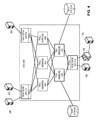
- FIG. 1A illustrates an exemplary virtual cluster switch system, in accordance with an embodiment of the present invention.
- a VCS 100 includes physical switches 101 , 102 , 103 , 104 , 105 , 106 , and 107 .
- a given physical switch runs an Ethernet-based transport protocol on its ports (e.g., TRILL on its inter-switch ports, and Ethernet transport on its external ports), while its control plane runs an FC switch fabric protocol stack.
- TRILL protocol facilitates transport of Ethernet frames within and across VCS 100 in a routed fashion (since TRILL provides routing functions to Ethernet frames).
- the FC switch fabric protocol stack facilitates the automatic configuration of individual physical switches, in a way similar to how a conventional FC switch fabric is formed and automatically configured.
- VCS 100 can appear externally as an ultra-high-capacity Ethernet switch. More details on FC network architecture, protocols, naming/address conventions, and various standards are available in the documentation available from the NCITS/ANSI T11 committee (www.t11.org) and publicly available literature, such as “Designing Storage Area Networks,” by Tom Clark, 2nd Ed., Addison Wesley, 2003, the disclosures of which are incorporated by reference in their entirety herein.
- a physical switch may dedicate a number of ports for external use (i.e., to be coupled to end hosts or other switches external to the VCS) and other ports for inter-switch connection.
- VCS 100 appears to be one switch to a device from the outside, and any port from any of the physical switches is considered one port on the VCS.
- port groups 110 and 112 are both VCS external ports and can be treated equally as if they were ports on a common physical switch, although switches 105 and 107 may reside in two different locations.
- the physical switches can reside at a common location, such as a data center or central office, or be distributed in different locations. Hence, it is possible to construct a large-scale centralized switching system using many smaller, inexpensive switches housed in one or more chassis at the same location. It is also possible to have the physical switches placed at different locations, thus creating a logical switch that can be accessed from multiple locations.
- the topology used to interconnect the physical switches can also be versatile.
- VCS 100 is based on a mesh topology. In further embodiments, a VCS can be based on a ring, fat tree, or other types of topologies.
- the protocol architecture of a VCS is based on elements from the standard IEEE 802.1Q Ethernet bridge, which is emulated over a transport based on the Fibre Channel Framing and Signaling-2 (FC-FS-2) standard.
- FC-FS-2 Fibre Channel Framing and Signaling-2
- FIG. 1B presents an exemplary VCS with its member switches connected in a CLOS network, in accordance with one embodiment of the present invention.
- a VCS 120 forms a fully non-blocking 8 ⁇ 8 switch, using eight 4 ⁇ 4 switches and four 2 ⁇ 2 switches connected in a three-stage CLOS network.
- a large-scale switch with a higher port count can be built in a similar way.
- FIG. 2 illustrates the protocol stack within a virtual cluster switch, in accordance with an embodiment of the present invention.
- Switch 202 includes an ingress Ethernet port 206 and an inter-switch port 208 .
- Switch 204 includes an egress Ethernet port 212 and an inter-switch port 210 .
- Ingress Ethernet port 206 receives Ethernet frames from an external device.
- the Ethernet header is processed by a medium access control (MAC) layer protocol.
- MAC medium access control
- FDB forwarding database
- FDB 214 is maintained locally in a switch, which would perform a lookup based on the destination MAC address and the VLAN indicated in the Ethernet frame. The lookup result would provide the corresponding output port. However, since VCS 200 is not one single physical switch, FDB 214 would return the egress switch's identifier (i.e., switch 204 's identifier). In one embodiment, FDB 214 is a data structure replicated and distributed among all the physical switches. That is, every physical switch maintains its own copy of FDB 214 .
- the forwarding of the Ethernet frame between ingress switch 202 and egress switch 204 is performed via inter-switch ports 208 and 210 .
- the frame transported between the two inter-switch ports is encapsulated in an outer MAC header and a TRILL header, in accordance with the TRILL standard.
- the protocol stack associated with a given inter-switch port includes the following (from bottom up): MAC layer, TRILL layer, FC-FS-2 layer, FC E-Port layer, and FC link services (FC-LS) layer.
- the FC-LS layer is responsible for maintaining the connectivity information of a physical switch's neighbor, and populating an FC routing information base (RIB) 222 . This operation is similar to what is done in an FC switch fabric.
- FC-LS protocol is also responsible for handling joining and departure of a physical switch in VCS 200 .
- the operation of the FC-LS layer is specified in the FC-LS standard, which is available at http://www.t11.org/ftp/t11/member/fc/ls/06-393v5.pdf, the disclosure of which is incorporated herein in its entirety.
- Path selector 218 performs a fabric shortest-path first (FSPF)-based route lookup in conjunction with RIB 222 , and identifies the next-hop switch within VCS 200 .
- FSPF fabric shortest-path first
- each physical switch includes an address manager 216 and a fabric controller 220 .
- Address manager 216 is responsible for configuring the address of a physical switch when the switch first joins the VCS. For example, when switch 202 first joins VCS 200 , address manager 216 can negotiate a new FC switch domain ID, which is subsequently used to identify the switch within VCS 200 .
- Fabric controller 220 is responsible for managing and configuring the logical FC switch fabric formed on the control plane of VCS 200 .
- VCS protocol architecture
- FC switch fabric with an Ethernet/TRILL transport.
- Each physical switch from an external point of view, appears to be a TRILL RBridge.
- the switch's control plane implements the FC switch fabric software.
- embodiments of the present invention facilitate the construction of an “Ethernet switch fabric” running on FC control software. This unique combination provides the VCS with automatic configuration capability and allows it to provide the ubiquitous Ethernet services in a very scalable fashion.
- FIG. 3 illustrates an exemplary configuration of a virtual cluster switch, in accordance with an embodiment of the present invention.
- a VCS 300 includes four physical switches 302 , 304 , 306 , and 308 .
- VCS 300 constitutes an access layer which is coupled to two aggregation switches 310 and 312 .
- the physical switches within VCS 300 are connected in a ring topology.
- Aggregation switch 310 or 312 can connect to any of the physical switches within VCS 300 .
- aggregation switch 310 is coupled to physical switches 302 and 308 .
- FIG. 4 illustrates an exemplary configuration of how a virtual cluster switch can be connected to different edge networks, in accordance with an embodiment of the present invention.
- a VCS 400 includes a number of TRILL RBridges 402 , 404 , 406 , 408 , and 410 , which are controlled by the FC switch-fabric control plane. Also included in VCS 400 are RBridges 412 , 414 , and 416 . Each RBridge has a number of edge ports which can be connected to external edge networks.
- RBridge 412 is coupled with hosts 420 and 422 via 10GE ports.
- RBridge 414 is coupled to a host 426 via a 10GE port.
- These RBridges have TRILL-based inter-switch ports for connection with other TRILL RBridges in VCS 400 .
- RBridge 416 is coupled to host 428 and an external Ethernet switch 430 , which is coupled to an external network that includes a host 424 .
- network equipment can also be coupled directly to any of the physical switches in VCS 400 .
- TRILL RBridge 408 is coupled to a data storage 417
- TRILL RBridge 410 is coupled to a data storage 418 .
- TRILL RBridges Although the physical switches within VCS 400 are labeled as “TRILL RBridges,” they are different from the conventional TRILL RBridge in the sense that they are controlled by the FC switch fabric control plane. In other words, the assignment of switch addresses, link discovery and maintenance, topology convergence, routing, and forwarding can be handled by the corresponding FC protocols. Particularly, each TRILL RBridge's switch ID or nickname is mapped from the corresponding FC switch domain ID, which can be automatically assigned when a switch joins VCS 400 (which is logically similar to an FC switch fabric).
- TRILL is only used as a transport between the switches within VCS 400 . This is because TRILL can readily accommodate native Ethernet frames. Also, the TRILL standards provide a ready-to-use forwarding mechanism that can be used in any routed network with arbitrary topology (although the actual routing in VCS is done by the FC switch fabric protocols). Embodiments of the present invention should be not limited to using only TRILL as the transport. Other protocols (such as multi-protocol label switching (MPLS) or Internet Protocol (IP)), either public or proprietary, can also be used for the transport.
- MPLS multi-protocol label switching
- IP Internet Protocol
- a VCS is created by instantiating a logical FC switch in the control plane of each switch.
- a virtual generic port (denoted as G_Port) is created for each Ethernet port on the RBridge.
- G_Port assumes the normal G_Port behavior from the FC switch perspective.
- the specific transition from a G_Port to either an FC F_Port or E_Port is determined by the underlying link and physical layer protocols. For example, if the physical Ethernet port is connected to an external device which lacks VCS capabilities, the corresponding G_Port will be turned into an F_Port. On the other hand, if the physical Ethernet port is connected to a switch with VCS capabilities and it is confirmed that the switch on the other side is part of a VCS, then the G_Port will be turned into an E_port.
- FIG. 5A illustrates how a logical Fibre Channel switch fabric is formed in a virtual cluster switch in conjunction with the example in FIG. 4 , in accordance with an embodiment of the present invention.
- RBridge 412 contains a virtual, logical FC switch 502 .
- logical FC switch 502 Corresponding to the physical Ethernet ports coupled to hosts 420 and 422 , logical FC switch 502 has two logical F_Ports, which are logically coupled to hosts 420 and 422 . In addition, two logical N_Ports, 506 and 504 , are created for hosts 420 and 422 , respectively.
- logical FC switch 502 On the VCS side, logical FC switch 502 has three logical E_Ports, which are to be coupled with other logical FC switches in the logical FC switch fabric in the VCS.
- RBridge 416 contains a virtual, logical FC switch 512 .
- logical FC switch 512 Corresponding to the physical Ethernet ports coupled to host 428 and external switch 430 , logical FC switch 512 has a logical F_Port coupled to host 428 , and a logical FL_Port coupled to switch 430 .
- a logical N_Port 510 is created for host 428
- a logical NL_Port 508 is created for switch 430 .
- the logical FL_Port is created because that port is coupled to a switch (switch 430 ), instead of a regular host, and therefore logical FC switch 512 assumes an arbitrated loop topology leading to switch 430 .
- Logical NL_Port 508 is created based on the same reasoning to represent a corresponding NL_Port on switch 430 .
- logical FC switch 512 On the VCS side, logical FC switch 512 has two logical E_Ports, which to be coupled with other logical FC switches in the logical FC switch fabric in the VCS.
- FIG. 5B illustrates an example of how a logical FC switch can be created within a physical Ethernet switch, in accordance with one embodiment of the present invention.
- fabric port refers to a port used to couple multiple switches in a VCS.
- the clustering protocols control the forwarding between fabric ports.
- edge port refers to a port that is not currently coupled to another switch unit in the VCS. Standard IEEE 802.1Q and layer-3 protocols control forwarding on edge ports.
- a logical FC switch 521 is created within a physical switch (RBridge) 520 .
- Logical FC switch 521 participates in the FC switch fabric protocol via logical inter-switch links (ISLs) to other switch units and has an FC switch domain ID assigned to it just as a physical FC switch does. In other words, the domain allocation, principal switch selection, and conflict resolution work just as they would on a physical FC ISL.
- ISLs logical inter-switch links
- the physical edge ports 522 and 524 are mapped to logical F_Ports 532 and 534 , respectively.
- physical fabric ports 526 and 528 are mapped to logical E_Ports 536 and 538 , respectively.
- logical FC switch 521 when logical FC switch 521 is created (for example, during the boot-up sequence), logical FC switch 521 only has four G_Ports which correspond to the four physical ports. These G_Ports are subsequently mapped to F_Ports or E_Ports, depending on the devices coupled to the physical ports.
- Neighbor discovery is the first step in VCS formation between two VCS-capable switches. It is assumed that the verification of VCS capability can be carried out by a handshake process between two neighbor switches when the link is first brought up.
- VCS presents itself as one unified switch composed of multiple member switches. Hence, the creation and configuration of VCS is of critical importance.
- the VCS configuration is based on a distributed database, which is replicated and distributed over all switches.
- a VCS configuration database includes a global configuration table (GT) of the VCS and a list of switch description tables (STs), each of which describes a VCS member switch.
- a member switch can have a VCS configuration database that includes a global table and one switch description table, e.g., [ ⁇ GT> ⁇ ST>].
- a VCS with multiple switches will have a configuration database that has a single global table and multiple switch description tables, e.g., [ ⁇ GT> ⁇ ST 0 > ⁇ ST 1 > . . . ⁇ STn ⁇ 1>].
- the number n corresponds to the number of member switches in the VCS.
- the GT can include at least the following information: the VCS_ID, number of nodes in the VCS, a list of VLANs supported by the VCS, a list of all the switches (e.g., list of FC switch domain IDs for all active switches) in the VCS, and the FC switch domain ID of the principal switch (as in a logical FC switch fabric).
- a switch description table can include at least the following information: the IN_VCS flag, indication whether the switch is a principal switch in the logical FC switch fabric, the FC switch domain ID for the switch, the FC world-wide name (WWN) for the corresponding logical FC switch; the mapped ID of the switch, and optionally the IP address of the switch.
- each switch's global configuration database is associated with a transaction ID.
- the transaction ID specifies the latest transaction (e.g., update or change) incurred to the global configuration database.
- the transaction IDs of the global configuration databases in two switches can be compared to determine which database has the most current information (i.e., the database with the more current transaction ID is more up-to-date).
- the transaction ID is the switch's serial number plus a sequential transaction number. This configuration can unambiguously resolve which switch has the latest configuration.
- VCS configuration database 600 describes the VCS configuration when the switch is part of a VCS.
- Default switch configuration table 604 describes the switch's default configuration.
- VCS configuration database 600 includes a GT 602 , which includes a VCS identifier (denoted as VCS_ID) and a VLAN list within the VCS.
- VCS_ID VCS identifier
- STn a number of STs, such as ST 0 , ST 1 , and STn. Each ST includes the corresponding member switch's MAC address and FC switch domain ID, as well as the switch's interface details. Note that each switch also has a VCS-mapped ID which is a switch index within the VCS.
- each switch also has a VCS-mapped ID (denoted as “mappedID”), which is a switch index within the VCS.
- mappedID is unique and persistent within the VCS. That is, when a switch joins the VCS for the first time, the VCS assigns a mapped ID to the switch. This mapped ID persists with the switch, even if the switch leaves the VCS. When the switch joins the VCS again at a later time, the same mapped ID is used by the VCS to retrieve previous configuration information for the switch. This feature can reduce the amount of configuration overhead in VCS.
- the persistent mapped ID allows the VCS to “recognize” a previously configured member switch when it re-joins the VCS, since a dynamically assigned FC fabric domain ID would change each time the member switch joins and is configured by the VCS.
- Default switch configuration table 604 has an entry for the mappedID that points to the corresponding ST in VCS configuration database 600 . Note that only VCS configuration database 600 is replicated and distributed to all switches in the VCS. Default switch configuration table 604 is local to a particular member switch.
- the “IN_VCS” value in default switch configuration table 604 indicates whether the member switch is part of a VCS.
- a switch is considered to be “in a VCS” when it is assigned one of the FC switch domains by the FC switch fabric with two or more switch domains. If a switch is part of an FC switch fabric that has only one switch domain, i.e., its own switch domain, then the switch is considered to be “not in a VCS.”
- the logical FC switch fabric formation process allocates a new switch domain ID to the joining switch. In one embodiment, only the switches directly connected to the new switch participate in the VCS join operation.
- the global configuration database of a joining switch is current and in sync with the global configuration database of the VCS based on a comparison of the transaction IDs of the two databases (e.g., when a member switch is temporarily disconnected from the VCS and re-connected shortly afterward), a trivial merge is performed. That is, the joining switch can be connected to the VCS, and no change or update to the global VCS configuration database is required.
- FIG. 7 illustrates an exemplary process of a switch joining a virtual cluster switch, in accordance with an embodiment of the present invention.
- a switch 702 is within an existing VCS, and a switch 704 is joining the VCS.
- both switches 702 and 704 trigger an FC State Change Notification (SCN) process.
- SCN FC State Change Notification
- both switches 702 and 704 perform a PRE-INVITE operation.
- the pre-invite operation involves the following process.
- both neighbors on each end of the link present to the other switch a VCS four-tuple of ⁇ Prior VCS_ID, SWITCH_MAC, mappedID, IN_VCS> from a prior incarnation, if any. Otherwise, the switch presents to the counterpart a default tuple. If the VCS_ID value was not set from a prior join operation, a VCS_ID value of ⁇ 1 is used. In addition, if a switch's IN_VCS flag is set to 0, it sends out its interface configuration to the neighboring switch. In the example in FIG. 7 , both switches 702 and 704 send the above information to the other switch.
- a driver switch for the join process is selected.
- switch 702 After switch 702 is selected as the driver switch, switch 702 then attempts to reserve a slot in the VCS configuration database corresponding to the mappedID value in switch 704 's PRE-INVITE information. Next, switch 702 searches the VCS configuration database for switch 704 's MAC address in any mappedID slot. If such a slot is found, switch 702 copies all information from the identified slot into the reserved slot. Otherwise, switch 702 copies the information received during the PRE-INVITE from switch 704 into the VCS configuration database. The updated VCS configuration database is then propagated to all the switches in the VCS as a prepare operation in the database (note that the update is not committed to the database yet).
- the prepare operation may or may not result in configuration conflicts, which may be flagged as warnings or fatal errors.
- Such conflicts can include inconsistencies between the joining switch's local configuration or policy setting and the VCS configuration. For example, a conflict arises when the joining switch is manually configured to allow packets with a particular VLAN value to pass through, whereas the VCS does not allow this VLAN value to enter the switch fabric from this particular RBridge (for example, when this VLAN value is reserved for other purposes).
- the prepare operation is handled locally and/or remotely in concert with other VCS member switches. If there is an un-resolvable conflict, switch 702 sends out a PRE-INVITE-FAILED message to switch 704 . Otherwise, switch 702 generates an INVITE message with the VCS's merged view of the switch (i.e., the updated VCS configuration database).
- switch 704 Upon receiving the INVITE message, switch 704 either accepts or rejects the INVITE. The INVITE can be rejected if the configuration in the INVITE is in conflict with what switch 704 can accept. If the INVITE is acceptable, switch 704 sends back an INVITE-ACCEPT message in response. The INVITE-ACCEPT message then triggers a final database commit throughout all member switches in the VCS. In other words, the updated VCS configuration database is updated, replicated, and distributed to all the switches in the VCS.
- each VCS switch unit performs source MAC address learning, similar to what an Ethernet bridge does.
- Each ⁇ MAC address, VLAN ⁇ tuple learned on a physical port on a VCS switch unit is registered into the local Fibre Channel Name Server (FC-NS) via a logical Nx_Port interface corresponding to that physical port. This registration binds the address learned to the specific interface identified by the Nx_Port.
- FC-NS Fibre Channel Name Server
- Each FC-NS instance on each VCS switch unit coordinates and distributes all locally learned ⁇ MAC address, VLAN ⁇ tuples with every other FC-NS instance in the fabric. This feature allows the dissemination of locally learned ⁇ MAC addresses, VLAN ⁇ information to every switch in the VCS.
- the learned MAC addresses are aged locally by individual switches.
- FIG. 8 presents a flowchart illustrating the process of looking up an ingress frame's destination MAC address and forwarding the frame in a VCS, in accordance with one embodiment of the present invention.
- a VCS switch receives an Ethernet frame at one of its Ethernet ports (operation 802 ).
- the switch then extracts the frame's destination MAC address and queries the local FC Name Server (operation 804 ).
- the switch determines whether the FC-NS returns an N_Port or an NL_Port identifier that corresponds to an egress Ethernet port (operation 806 ).
- the switch forwards the frame to the identified N_Port or NL_Port (operation 808 ). Otherwise, the switch floods the frame on the TRILL multicast tree as well as on all the N_Ports and NL_Ports that participate in that VLAN (operation 810 ).
- This flood/broadcast operation is similar to the broadcast process in a conventional TRILL RBridge, wherein all the physical switches in the VCS will receive and process this frame, and learn the source address corresponding to the ingress RBridge.
- each receiving switch floods the frame to its local ports that participate in the frame's VLAN (operation 812 ).
- FIG. 9 illustrates how data frames and control frames are transported in a VCS, in accordance with an embodiment of the present invention.
- a VCS 930 includes member switches 934 , 936 , 938 , 944 , 946 , and 948 .
- An end host 932 is communicating with an end host 940 .
- Switch 934 is the ingress VCS member switch corresponding to host 932
- switch 938 is the egress VCS member switch corresponding to host 938 .
- host 932 sends an Ethernet frame 933 to host 940 .
- Ethernet frame 933 is first encountered by ingress switch 934 .
- switch 934 Upon receiving frame 933 , switch 934 first extracts frame 933 's destination MAC address.
- Switch 934 then performs a MAC address lookup using the Ethernet name service, which provides the egress switch identifier (i.e., the RBridge identifier of egress switch 938 ). Based on the egress switch identifier, the logical FC switch in switch 934 performs a routing table lookup to determine the next-hop switch, which is switch 936 , and the corresponding output port for forwarding frame 933 . The egress switch identifier is then used to generate a TRILL header (which specifies the destination switch's RBridge identifier), and the next-hop switch information is used to generate an outer Ethernet header.
- the egress switch identifier i.e., the RBridge identifier of egress switch 938
- switch 934 encapsulates frame 933 with the proper TRILL header and outer Ethernet header, and sends the encapsulated frame 935 to switch 936 .
- switch 936 Based on the destination RBridge identifier in the TRILL header of frame 935 , switch 936 performs a routing table lookup and determines the next hop. Based on the next-hop information, switch 936 updates frame 935 's outer Ethernet header and forwards frame 935 to egress switch 938 .
- switch 938 Upon receiving frame 935 , switch 938 determines that it is the destination RBridge based on frame 935 's TRILL header. Correspondingly, switch 938 strips frame 935 of its outer Ethernet header and TRILL header, and inspects the destination MAC address of its inner Ethernet header. Switch 938 then performs a MAC address lookup and determines the correct output port leading to host 940 . Subsequently, the original Ethernet frame 933 is transmitted to host 940 .
- the logical FC switches within the physical VCS member switches may send control frames to one another (for example, to update the VCS global configuration database or to notify other switches of the learned MAC addresses).
- control frames can be FC control frames encapsulated in a TRILL header and an outer Ethernet header.
- switch 944 can sends a TRILL-encapsulated FC control frame 942 to switch 946 .
- Switch 946 can forward frame 942 just like a regular data frame, since switch 946 is not concerned with the payload in frame 942 .
- FIG. 10 illustrates an exemplary equal cost multi-pathing configuration in a VCS, in accordance with one embodiment of the present invention.
- a VCS 1030 includes switches 1034 , 1036 , 1038 , 1044 , 1046 , and 1048 .
- switches 1034 , 1036 , 1038 , 1044 , 1046 , and 1048 Assume that a traffic flow enters VCS 1030 via ingress switch 1034 and exits VCS 1030 via egress switch 1048 . Based on the hop distance, there are two equal-cost data paths, 1050 and 1052 .
- switch 1034 's forwarding engine when determining the output interface, can return two possible output ports, corresponding to data paths 1050 and 1052 , respectively. If load balancing is desired, traffic from switch 1034 to switch 1048 can be split between the two data paths.
- the traffic splitting can be based on any field in a frame header.
- the traffic can be split based on VLAN tags.
- the traffic can also be split based on layer-4 port numbers or application types.
- the VCS can achieve loss-less packet transport by implementing a number of flow control mechanisms.
- the VCS member switches implement a priority-based flow control (PFC)-like mechanism to ensure a loss-less packet transport between neighboring switches.
- PFC priority-based flow control
- traffic class is identified by the VLAN tag priority values.
- Priority-based flow control is intended to eliminate frame loss due to congestion. This is achieved by a mechanism similar to the IEEE 802.3x PAUSE, but operating on individual priorities. This mechanism enables support for higher layer protocols that are highly loss sensitive while not affecting the operation of traditional LAN protocols utilizing other priorities. Details of PFC can be found in the IEEE 802.1Qbb standard, available at http://www.ieee802.org/1/pages/802.1bb.html, which is incorporated by reference herein.
- the VCS member switch also employ enhanced transmission selection mechanisms, which support allocation of bandwidth amongst different traffic classes.
- enhanced transmission selection will allow other traffic classes to use the available bandwidth.
- the bandwidth-allocation priorities can coexist with strict priorities.
- the VCS can prioritize traffic to provide different service characteristics to traffic classes. It is possible to share bandwidth between priorities carrying bursty loads rather than servicing them with strict priority while allowing strict priority for time-sensitive and management traffic requiring minimum latency. Also, when traffic at a given priority level does not use its allocation, it is possible to allow other priorities to use that bandwidth. Details of ETS can be found in the IEEE 802.1Qas standard, available at http://www.ieee802.org/1/pages/802.1az.html, which is incorporated by reference herein.
- the VCS member switches can also implement congestion notification mechanisms to facilitate source-oriented flow control.
- FIG. 11 illustrates an example of VCS congestion notification, in accordance with one embodiment of the present invention.
- a source host 1102 is transmitting frames to a destination host 1104 via a VCS 1100 .
- congestion occurs at an intermediary switch 1106 .
- As frames accumulate at switch 1106 its corresponding queue 1108 becomes full.
- a queue monitoring mechanism within switch 1106 is triggered when the content of queue 1108 passes a predetermined threshold.
- switch 1106 can randomly select a frame in queue 1108 , extract the source MAC address of the selected frame to construct a congestion notification frame, and send this notification frame to the source device corresponding to the extracted source MAC address (which is host 1102 ).
- Switch 1106 can perform the same action with multiple frames in queue 1108 , so that if multiple sources are contributing to the congestion, these sources can all be notified.
- FIG. 12 illustrates an exemplary hybrid trunk in accordance with one embodiment of the present invention.
- two link trunk groups 1206 and 1208 are formed between VCS member switches 1202 and 1204 .
- trunk groups 1206 and 1208 can be identified by both switches without using a link aggregation group (LAG) ID
- LAG link aggregation group
- trunks 1206 and 1208 can be regarded as logical links.
- LAG 1210 can also include other individual, physical links (not shown).
- FIG. 13 illustrates an exemplary VCS member switch, in accordance with one embodiment of the present invention.
- the VCS member switch is a TRILL RBridge 1300 running special VCS software.
- RBridge 1300 includes a number of Ethernet communication ports 1301 , which can transmit and receive Ethernet frames and/or TRILL encapsulated frames.
- Also included in RBridge 1300 is a packet processor 1302 , a virtual FC switch management module 1304 , a logical FC switch 1305 , a VCS configuration database 1306 , a traffic management module 1307 , and a TRILL header generation module 1308 .
- packet processor 1302 extracts the source and destination MAC addresses of incoming frames, and attaches proper Ethernet or TRILL headers to outgoing frames.
- Virtual FC switch management module 1304 maintains the state of logical FC switch 1305 , which is used to join other VCS switches using the FC switch fabric protocols.
- VCS configuration database 1306 maintains the configuration state of every switch within the VCS.
- TRILL header generation module 1308 is responsible for generating property TRILL headers for frames that are to be transmitted to other VCS member switches.
- Traffic management module 1307 facilitates the aforementioned traffic management functions, such as multi-pathing, flow control, congestion notification, and hybrid trunking.
- the methods and processes described herein can be embodied as code and/or data, which can be stored in a computer-readable non-transitory storage medium.
- a computer system reads and executes the code and/or data stored on the computer-readable non-transitory storage medium, the computer system performs the methods and processes embodied as data structures and code and stored within the medium.
- the methods and processes described herein can be executed by and/or included in hardware modules or apparatus.
- These modules or apparatus may include, but are not limited to, an application-specific integrated circuit (ASIC) chip, a field-programmable gate array (FPGA), a dedicated or shared processor that executes a particular software module or a piece of code at a particular time, and/or other programmable-logic devices now known or later developed.
- ASIC application-specific integrated circuit
- FPGA field-programmable gate array
- a dedicated or shared processor that executes a particular software module or a piece of code at a particular time
- other programmable-logic devices now known or later developed.
Abstract
Description
Claims (19)
Priority Applications (10)
| Application Number | Priority Date | Filing Date | Title |
|---|---|---|---|
| US13/092,877 US9231890B2 (en) | 2010-06-08 | 2011-04-22 | Traffic management for virtual cluster switching |
| CN201180030594.5A CN102986172B (en) | 2010-05-03 | 2011-05-03 | Virtual Cluster exchanges |
| US14/912,585 US20170155599A1 (en) | 2010-05-03 | 2011-05-03 | Virtual cluster switching |
| CA2797278A CA2797278A1 (en) | 2010-05-03 | 2011-05-03 | Virtual cluster switching |
| EP16155677.4A EP3041173B1 (en) | 2010-05-03 | 2011-05-03 | Virtual cluster switching |
| EP21211732.9A EP4027611A1 (en) | 2010-05-03 | 2011-05-03 | Virtual cluster switching |
| CN201610899192.3A CN106850381B (en) | 2010-05-03 | 2011-05-03 | Switching system, switching device, switch and method executed by the same |
| EP11721162.3A EP2567512B1 (en) | 2010-05-03 | 2011-05-03 | Virtual cluster switching |
| JP2013509167A JP5801383B2 (en) | 2010-05-03 | 2011-05-03 | Virtual cluster exchange |
| PCT/US2011/034917 WO2011140028A1 (en) | 2010-05-03 | 2011-05-03 | Virtual cluster switching |
Applications Claiming Priority (2)
| Application Number | Priority Date | Filing Date | Title |
|---|---|---|---|
| US35281910P | 2010-06-08 | 2010-06-08 | |
| US13/092,877 US9231890B2 (en) | 2010-06-08 | 2011-04-22 | Traffic management for virtual cluster switching |
Related Parent Applications (1)
| Application Number | Title | Priority Date | Filing Date |
|---|---|---|---|
| US13/092,724 Continuation US9001824B2 (en) | 2010-05-03 | 2011-04-22 | Fabric formation for virtual cluster switching |
Related Child Applications (1)
| Application Number | Title | Priority Date | Filing Date |
|---|---|---|---|
| US13/092,701 Continuation US8989186B2 (en) | 2010-05-03 | 2011-04-22 | Virtual port grouping for virtual cluster switching |
Publications (2)
| Publication Number | Publication Date |
|---|---|
| US20110299391A1 US20110299391A1 (en) | 2011-12-08 |
| US9231890B2 true US9231890B2 (en) | 2016-01-05 |
Family
ID=45064380
Family Applications (1)
| Application Number | Title | Priority Date | Filing Date |
|---|---|---|---|
| US13/092,877 Active 2031-10-05 US9231890B2 (en) | 2010-05-03 | 2011-04-22 | Traffic management for virtual cluster switching |
Country Status (1)
| Country | Link |
|---|---|
| US (1) | US9231890B2 (en) |
Cited By (26)
| Publication number | Priority date | Publication date | Assignee | Title |
|---|---|---|---|---|
| US20150071122A1 (en) * | 2013-09-06 | 2015-03-12 | Brocade Communications Systems, Inc. | Transparent inteconnection of ethernet fabric switches |
| US9848040B2 (en) | 2010-06-07 | 2017-12-19 | Brocade Communications Systems, Inc. | Name services for virtual cluster switching |
| US9912614B2 (en) | 2015-12-07 | 2018-03-06 | Brocade Communications Systems LLC | Interconnection of switches based on hierarchical overlay tunneling |
| US9912612B2 (en) | 2013-10-28 | 2018-03-06 | Brocade Communications Systems LLC | Extended ethernet fabric switches |
| US9942097B2 (en) | 2015-01-05 | 2018-04-10 | Brocade Communications Systems LLC | Power management in a network of interconnected switches |
| US9942173B2 (en) | 2010-05-28 | 2018-04-10 | Brocade Communications System Llc | Distributed configuration management for virtual cluster switching |
| US9998365B2 (en) | 2012-05-18 | 2018-06-12 | Brocade Communications Systems, LLC | Network feedback in software-defined networks |
| US10003552B2 (en) | 2015-01-05 | 2018-06-19 | Brocade Communications Systems, Llc. | Distributed bidirectional forwarding detection protocol (D-BFD) for cluster of interconnected switches |
| US10038592B2 (en) | 2015-03-17 | 2018-07-31 | Brocade Communications Systems LLC | Identifier assignment to a new switch in a switch group |
| US10044568B2 (en) | 2014-05-13 | 2018-08-07 | Brocade Communications Systems LLC | Network extension groups of global VLANs in a fabric switch |
| US10063473B2 (en) | 2014-04-30 | 2018-08-28 | Brocade Communications Systems LLC | Method and system for facilitating switch virtualization in a network of interconnected switches |
| US10075394B2 (en) | 2012-11-16 | 2018-09-11 | Brocade Communications Systems LLC | Virtual link aggregations across multiple fabric switches |
| US10164883B2 (en) | 2011-11-10 | 2018-12-25 | Avago Technologies International Sales Pte. Limited | System and method for flow management in software-defined networks |
| US10171303B2 (en) | 2015-09-16 | 2019-01-01 | Avago Technologies International Sales Pte. Limited | IP-based interconnection of switches with a logical chassis |
| US10237090B2 (en) | 2016-10-28 | 2019-03-19 | Avago Technologies International Sales Pte. Limited | Rule-based network identifier mapping |
| US10284469B2 (en) | 2014-08-11 | 2019-05-07 | Avago Technologies International Sales Pte. Limited | Progressive MAC address learning |
| US10348643B2 (en) | 2010-07-16 | 2019-07-09 | Avago Technologies International Sales Pte. Limited | System and method for network configuration |
| US10355879B2 (en) | 2014-02-10 | 2019-07-16 | Avago Technologies International Sales Pte. Limited | Virtual extensible LAN tunnel keepalives |
| US10419276B2 (en) | 2010-06-07 | 2019-09-17 | Avago Technologies International Sales Pte. Limited | Advanced link tracking for virtual cluster switching |
| US10439929B2 (en) | 2015-07-31 | 2019-10-08 | Avago Technologies International Sales Pte. Limited | Graceful recovery of a multicast-enabled switch |
| US10462049B2 (en) | 2013-03-01 | 2019-10-29 | Avago Technologies International Sales Pte. Limited | Spanning tree in fabric switches |
| US10476698B2 (en) | 2014-03-20 | 2019-11-12 | Avago Technologies International Sales Pte. Limited | Redundent virtual link aggregation group |
| US10579406B2 (en) | 2015-04-08 | 2020-03-03 | Avago Technologies International Sales Pte. Limited | Dynamic orchestration of overlay tunnels |
| US10581758B2 (en) | 2014-03-19 | 2020-03-03 | Avago Technologies International Sales Pte. Limited | Distributed hot standby links for vLAG |
| US10616108B2 (en) | 2014-07-29 | 2020-04-07 | Avago Technologies International Sales Pte. Limited | Scalable MAC address virtualization |
| US10673703B2 (en) | 2010-05-03 | 2020-06-02 | Avago Technologies International Sales Pte. Limited | Fabric switching |
Families Citing this family (63)
| Publication number | Priority date | Publication date | Assignee | Title |
|---|---|---|---|---|
| US8665886B2 (en) | 2009-03-26 | 2014-03-04 | Brocade Communications Systems, Inc. | Redundant host connection in a routed network |
| US8369335B2 (en) | 2010-03-24 | 2013-02-05 | Brocade Communications Systems, Inc. | Method and system for extending routing domain to non-routing end stations |
| US9231890B2 (en) | 2010-06-08 | 2016-01-05 | Brocade Communications Systems, Inc. | Traffic management for virtual cluster switching |
| US8989186B2 (en) | 2010-06-08 | 2015-03-24 | Brocade Communication Systems, Inc. | Virtual port grouping for virtual cluster switching |
| US9461840B2 (en) | 2010-06-02 | 2016-10-04 | Brocade Communications Systems, Inc. | Port profile management for virtual cluster switching |
| US9001824B2 (en) | 2010-05-18 | 2015-04-07 | Brocade Communication Systems, Inc. | Fabric formation for virtual cluster switching |
| US8625616B2 (en) | 2010-05-11 | 2014-01-07 | Brocade Communications Systems, Inc. | Converged network extension |
| US8634308B2 (en) | 2010-06-02 | 2014-01-21 | Brocade Communications Systems, Inc. | Path detection in trill networks |
| US8885488B2 (en) | 2010-06-02 | 2014-11-11 | Brocade Communication Systems, Inc. | Reachability detection in trill networks |
| US9608833B2 (en) | 2010-06-08 | 2017-03-28 | Brocade Communications Systems, Inc. | Supporting multiple multicast trees in trill networks |
| US9246703B2 (en) | 2010-06-08 | 2016-01-26 | Brocade Communications Systems, Inc. | Remote port mirroring |
| US9628293B2 (en) | 2010-06-08 | 2017-04-18 | Brocade Communications Systems, Inc. | Network layer multicasting in trill networks |
| US9806906B2 (en) | 2010-06-08 | 2017-10-31 | Brocade Communications Systems, Inc. | Flooding packets on a per-virtual-network basis |
| US8446914B2 (en) | 2010-06-08 | 2013-05-21 | Brocade Communications Systems, Inc. | Method and system for link aggregation across multiple switches |
| US8929218B2 (en) * | 2010-09-10 | 2015-01-06 | Brocade Communication Systems, Inc. | Congestion notification across multiple layer-2 domains |
| US20120163164A1 (en) * | 2010-12-27 | 2012-06-28 | Brocade Communications Systems, Inc. | Method and system for remote load balancing in high-availability networks |
| US20120170462A1 (en) * | 2011-01-05 | 2012-07-05 | Alcatel Lucent Usa Inc. | Traffic flow control based on vlan and priority |
| US8989009B2 (en) | 2011-04-29 | 2015-03-24 | Futurewei Technologies, Inc. | Port and priority based flow control mechanism for lossless ethernet |
| US9270572B2 (en) | 2011-05-02 | 2016-02-23 | Brocade Communications Systems Inc. | Layer-3 support in TRILL networks |
| US8693341B2 (en) * | 2011-06-10 | 2014-04-08 | Force10 Networks, Inc. | Method and apparatus for optimizing data traffic path through a stacked switch LAG configuration |
| US9401861B2 (en) | 2011-06-28 | 2016-07-26 | Brocade Communications Systems, Inc. | Scalable MAC address distribution in an Ethernet fabric switch |
| US9407533B2 (en) | 2011-06-28 | 2016-08-02 | Brocade Communications Systems, Inc. | Multicast in a trill network |
| US8948056B2 (en) | 2011-06-28 | 2015-02-03 | Brocade Communication Systems, Inc. | Spanning-tree based loop detection for an ethernet fabric switch |
| US8879549B2 (en) | 2011-06-28 | 2014-11-04 | Brocade Communications Systems, Inc. | Clearing forwarding entries dynamically and ensuring consistency of tables across ethernet fabric switch |
| US9007958B2 (en) | 2011-06-29 | 2015-04-14 | Brocade Communication Systems, Inc. | External loop detection for an ethernet fabric switch |
| US8885641B2 (en) | 2011-06-30 | 2014-11-11 | Brocade Communication Systems, Inc. | Efficient trill forwarding |
| US9736085B2 (en) | 2011-08-29 | 2017-08-15 | Brocade Communications Systems, Inc. | End-to end lossless Ethernet in Ethernet fabric |
| US9699117B2 (en) | 2011-11-08 | 2017-07-04 | Brocade Communications Systems, Inc. | Integrated fibre channel support in an ethernet fabric switch |
| US9231870B2 (en) | 2011-12-22 | 2016-01-05 | International Business Machines Corporation | Flexible and scalable data link layer flow control for network fabrics |
| US8995272B2 (en) | 2012-01-26 | 2015-03-31 | Brocade Communication Systems, Inc. | Link aggregation in software-defined networks |
| US9742693B2 (en) | 2012-02-27 | 2017-08-22 | Brocade Communications Systems, Inc. | Dynamic service insertion in a fabric switch |
| US9154416B2 (en) | 2012-03-22 | 2015-10-06 | Brocade Communications Systems, Inc. | Overlay tunnel in a fabric switch |
| US10277464B2 (en) | 2012-05-22 | 2019-04-30 | Arris Enterprises Llc | Client auto-configuration in a multi-switch link aggregation |
| WO2013177289A1 (en) | 2012-05-23 | 2013-11-28 | Brocade Communications Systems, Inc. | Layer-3 overlay gateways |
| JP6007595B2 (en) * | 2012-05-28 | 2016-10-12 | 富士通株式会社 | Transmission method, apparatus and program |
| US9602430B2 (en) | 2012-08-21 | 2017-03-21 | Brocade Communications Systems, Inc. | Global VLANs for fabric switches |
| CN102891803B (en) * | 2012-10-10 | 2015-05-13 | 华为技术有限公司 | Congestion processing method and network device |
| CN103856397B (en) | 2012-12-07 | 2018-08-14 | 中兴通讯股份有限公司 | Multicast forward method and device, routing bridge in transparent interconnection of lots of links interference networks |
| US9413691B2 (en) | 2013-01-11 | 2016-08-09 | Brocade Communications Systems, Inc. | MAC address synchronization in a fabric switch |
| US9350680B2 (en) | 2013-01-11 | 2016-05-24 | Brocade Communications Systems, Inc. | Protection switching over a virtual link aggregation |
| US9548926B2 (en) | 2013-01-11 | 2017-01-17 | Brocade Communications Systems, Inc. | Multicast traffic load balancing over virtual link aggregation |
| CN103460675B (en) | 2013-01-14 | 2016-09-28 | 华为技术有限公司 | Cluster and retransmission method |
| US9565113B2 (en) | 2013-01-15 | 2017-02-07 | Brocade Communications Systems, Inc. | Adaptive link aggregation and virtual link aggregation |
| US9379976B2 (en) | 2013-03-13 | 2016-06-28 | Brocade Communications Systems, Inc. | FCoE VN—port to FC N—port operations in an ethernet fabric |
| US9401818B2 (en) | 2013-03-15 | 2016-07-26 | Brocade Communications Systems, Inc. | Scalable gateways for a fabric switch |
| US9397958B2 (en) | 2013-04-04 | 2016-07-19 | Brocade Communications Systems, Inc. | FCoE VN—port virtualizer |
| US9692706B2 (en) * | 2013-04-15 | 2017-06-27 | International Business Machines Corporation | Virtual enhanced transmission selection (VETS) for lossless ethernet |
| US9565028B2 (en) | 2013-06-10 | 2017-02-07 | Brocade Communications Systems, Inc. | Ingress switch multicast distribution in a fabric switch |
| US9699001B2 (en) | 2013-06-10 | 2017-07-04 | Brocade Communications Systems, Inc. | Scalable and segregated network virtualization |
| US9438439B2 (en) * | 2013-10-30 | 2016-09-06 | Aruba Networks, Inc. | Dynamic optimization of advertisement packets |
| US20150149536A1 (en) * | 2013-11-27 | 2015-05-28 | Sharp Kabushiki Kaisha | Network system, constant connection method, communication method, electronic device, constant connection server, application server, and program |
| KR20160011774A (en) * | 2014-07-22 | 2016-02-02 | 한국전자통신연구원 | Network path setup method based on identifier, and apparatus thereof |
| US9544219B2 (en) | 2014-07-31 | 2017-01-10 | Brocade Communications Systems, Inc. | Global VLAN services |
| US9524173B2 (en) | 2014-10-09 | 2016-12-20 | Brocade Communications Systems, Inc. | Fast reboot for a switch |
| US9699029B2 (en) | 2014-10-10 | 2017-07-04 | Brocade Communications Systems, Inc. | Distributed configuration management in a switch group |
| US9628407B2 (en) | 2014-12-31 | 2017-04-18 | Brocade Communications Systems, Inc. | Multiple software versions in a switch group |
| US9626255B2 (en) | 2014-12-31 | 2017-04-18 | Brocade Communications Systems, Inc. | Online restoration of a switch snapshot |
| US9807005B2 (en) | 2015-03-17 | 2017-10-31 | Brocade Communications Systems, Inc. | Multi-fabric manager |
| US10693832B1 (en) | 2015-12-30 | 2020-06-23 | Avago Technologies International Sales Pte. Limited | Address resolution protocol operation in a fibre channel fabric |
| US10333866B1 (en) | 2016-10-21 | 2019-06-25 | Avago Technologies International Sales Pte. Limited | Soft zoning of virtual local area networks in a fibre channel fabric |
| US10348859B1 (en) | 2016-10-21 | 2019-07-09 | Avago Technologies International Sales Pte. Limited | Automatic zoning of virtual local area networks in a fibre channel fabric |
| US10374980B1 (en) | 2016-10-21 | 2019-08-06 | Avago Technologies International Sales Pte. Limited | Hard zoning of virtual local area networks in a fibre channel fabric |
| US10560550B1 (en) | 2017-04-10 | 2020-02-11 | Juniper Networks, Inc. | Automatic configuration of a replacement network device in a high-availability cluster |
Citations (262)
| Publication number | Priority date | Publication date | Assignee | Title |
|---|---|---|---|---|
| US5390173A (en) | 1992-10-22 | 1995-02-14 | Digital Equipment Corporation | Packet format in hub for packet data communications system |
| US5802278A (en) | 1995-05-10 | 1998-09-01 | 3Com Corporation | Bridge/router architecture for high performance scalable networking |
| US5959968A (en) | 1997-07-30 | 1999-09-28 | Cisco Systems, Inc. | Port aggregation protocol |
| US5973278A (en) | 1998-05-07 | 1999-10-26 | Eaton Corporation | Snap acting charge/discharge and open/closed indicators displaying states of electrical switching apparatus |
| US5983278A (en) * | 1996-04-19 | 1999-11-09 | Lucent Technologies Inc. | Low-loss, fair bandwidth allocation flow control in a packet switch |
| US6041042A (en) | 1997-05-27 | 2000-03-21 | Cabletron Systems, Inc. | Remote port mirroring system and method thereof |
| US6085238A (en) | 1996-04-23 | 2000-07-04 | Matsushita Electric Works, Ltd. | Virtual LAN system |
| US6104696A (en) | 1998-07-08 | 2000-08-15 | Broadcom Corporation | Method for sending packets between trunk ports of network switches |
| US6185241B1 (en) | 1998-10-29 | 2001-02-06 | Xerox Corporation | Metal spatial filter to enhance model reflectivity in a vertical cavity surface emitting laser |
| US6185214B1 (en) | 1997-09-11 | 2001-02-06 | 3Com Corporation | Use of code vectors for frame forwarding in a bridge/router |
| US20010055274A1 (en) | 2000-02-22 | 2001-12-27 | Doug Hegge | System and method for flow mirroring in a network switch |
| US20020021701A1 (en) | 2000-08-21 | 2002-02-21 | Lavian Tal I. | Dynamic assignment of traffic classes to a priority queue in a packet forwarding device |
| US20020091795A1 (en) | 2001-01-05 | 2002-07-11 | Michael Yip | Method and system of aggregate multiple VLANs in a metropolitan area network |
| US6438106B1 (en) * | 1998-12-22 | 2002-08-20 | Nortel Networks Limited | Inter-class schedulers utilizing statistical priority guaranteed queuing and generic cell-rate algorithm priority guaranteed queuing |
| US20030041085A1 (en) | 2001-08-23 | 2003-02-27 | Kazuhiko Sato | Management system and method for network devices using information recordable medium |
| US6542266B1 (en) | 1999-06-24 | 2003-04-01 | Qwest Communications International Inc. | System and method for providing broadband data service |
| US20030123393A1 (en) | 2002-01-03 | 2003-07-03 | Feuerstraeter Mark T. | Method and apparatus for priority based flow control in an ethernet architecture |
| US20030174706A1 (en) | 2002-03-15 | 2003-09-18 | Broadcom Corporation | Fastpath implementation for transparent local area network (LAN) services over multiprotocol label switching (MPLS) |
| US20030189905A1 (en) | 2002-04-03 | 2003-10-09 | Accton Technology Corporation | Method of setting network configuration and device and system thereof |
| US6633761B1 (en) | 2000-08-11 | 2003-10-14 | Reefedge, Inc. | Enabling seamless user mobility in a short-range wireless networking environment |
| US20040001433A1 (en) | 2001-07-18 | 2004-01-01 | Gram Charles Andrew | Interactive control of network devices |
| US20040010600A1 (en) | 2002-07-09 | 2004-01-15 | Baldwin Duane Mark | Methods and apparatus for storage area network component registration |
| US20040049699A1 (en) | 2002-09-06 | 2004-03-11 | Capital One Financial Corporation | System and method for remotely monitoring wireless networks |
| EP1398920A2 (en) | 2002-08-27 | 2004-03-17 | Alcatel Canada Inc. | Stackable virtual local area network provisioning in bridged networks |
| US20040117508A1 (en) | 2002-02-20 | 2004-06-17 | Keiichi Shimizu | Mobile body network |
| US20040120326A1 (en) | 2002-12-24 | 2004-06-24 | Hyeon-Sik Yoon | System and method for VLAN configuration of E-PON, and recording medium with stored program thereof |
| US20040165595A1 (en) | 2003-02-25 | 2004-08-26 | At&T Corp. | Discovery and integrity testing method in an ethernet domain |
| US20040213232A1 (en) | 2003-04-28 | 2004-10-28 | Alcatel Ip Networks, Inc. | Data mirroring in a service |
| US20050007951A1 (en) | 2003-07-11 | 2005-01-13 | Roger Lapuh | Routed split multilink trunking |
| US20050044199A1 (en) | 2003-08-06 | 2005-02-24 | Kenta Shiga | Storage network management system and method |
| US6873602B1 (en) | 1999-08-06 | 2005-03-29 | Fujitsu Limited | Network system, switch, and server |
| US20050094630A1 (en) | 2003-10-31 | 2005-05-05 | Ezio Valdevit | Network path tracing method |
| US20050094568A1 (en) | 2003-10-31 | 2005-05-05 | Josh Judd | Network path tracing method |
| US20050122979A1 (en) | 2003-11-13 | 2005-06-09 | David Gross | System and method for traversing metadata across multiple network domains at various layers of the protocol stack |
| US20050157751A1 (en) | 2004-01-20 | 2005-07-21 | Sameh Rabie | Method and system for ethernet and frame relay network interworking |
| US20050169188A1 (en) | 2002-06-12 | 2005-08-04 | Andiamo Systems, Inc. | Methods and apparatus for characterizing a route in a fibre channel fabric |
| US20050195813A1 (en) * | 2004-02-23 | 2005-09-08 | Sinett Corporation | Unified architecture for wired and wireless networks |
| US20050213561A1 (en) | 2001-10-26 | 2005-09-29 | Maxxan Systems, Inc. | System, apparatus and method for address forwarding for a computer network |
| US6957269B2 (en) | 2001-01-03 | 2005-10-18 | Advanced Micro Devices, Inc. | Method and apparatus for performing priority-based flow control |
| US6956824B2 (en) | 2001-06-14 | 2005-10-18 | Tropic Networks Inc. | Extension of link aggregation protocols over the network |
| US20050265356A1 (en) | 2004-05-14 | 2005-12-01 | Fujitsu Limited | Method and apparatus for keeping track of virtual LAN topology in network of nodes |
| US6975581B1 (en) | 1998-07-08 | 2005-12-13 | Marvell Semiconductor Israel Ltd. | VLAN protocol |
| US20050278565A1 (en) | 2004-03-10 | 2005-12-15 | Enterasys Networks, Inc. | Method for network traffic mirroring with data privacy |
| US20060018302A1 (en) | 2004-07-22 | 2006-01-26 | Alcatel | Local area network with one or more virtual groups of core equipments appropriate for layer 2 switching |
| US20060034292A1 (en) | 2000-06-02 | 2006-02-16 | Koji Wakayama | Apparatus and method for interworking between MPLS network and non-MPLS network |
| US20060059163A1 (en) | 2004-08-20 | 2006-03-16 | Enterasys Networks, Inc. | System, method and apparatus for traffic mirror setup, service and security in communication networks |
| US7016352B1 (en) | 2001-03-23 | 2006-03-21 | Advanced Micro Devices, Inc. | Address modification within a switching device in a packet-switched network |
| US20060062187A1 (en) | 2002-10-04 | 2006-03-23 | Johan Rune | Isolation of hosts connected to an access network |
| US20060072550A1 (en) | 2004-10-06 | 2006-04-06 | Davis Thomas C | Providing CALEA/LegaI Intercept information to law enforcement agencies for internet protocol multimedia subsystems (IMS) |
| US20060083254A1 (en) | 2004-10-15 | 2006-04-20 | An Ge | Network with MAC table overflow protection |
| US20060168109A1 (en) | 2004-11-12 | 2006-07-27 | Brocade Communications Systems, Inc. | Methods, devices and systems with improved zone merge operation by operating on a switch basis |
| US20060184937A1 (en) | 2005-02-11 | 2006-08-17 | Timothy Abels | System and method for centralized software management in virtual machines |
| US20060221960A1 (en) | 2005-04-01 | 2006-10-05 | Gaetano Borgione | Performing extended lookups on mac-based tables |
| US20060235995A1 (en) | 2005-04-18 | 2006-10-19 | Jagjeet Bhatia | Method and system for implementing a high availability VLAN |
| US20060242311A1 (en) | 2000-06-29 | 2006-10-26 | Khanh Mai | Virtual multicasting |
| US20060245439A1 (en) | 2005-04-28 | 2006-11-02 | Cisco Technology, Inc. | System and method for DSL subscriber identification over ethernet network |
| US20060251067A1 (en) * | 2004-10-22 | 2006-11-09 | Cisco Technology, Inc., A Corporation Of California | Fibre channel over ethernet |
| US20060256767A1 (en) | 2003-06-11 | 2006-11-16 | Nec Corporation | Router and network connecting method |
| US20060285499A1 (en) | 2005-06-17 | 2006-12-21 | Broadcom Corporation | Loop detection for a network device |
| US20060291388A1 (en) * | 2001-05-24 | 2006-12-28 | F5 Networks, Inc. | Method and system for scaling network traffic managers |
| US7173934B2 (en) | 2001-09-10 | 2007-02-06 | Nortel Networks Limited | System, device, and method for improving communication network reliability using trunk splitting |
| US20070036178A1 (en) | 2005-02-02 | 2007-02-15 | Susan Hares | Layer 2 virtual switching environment |
| US20070086362A1 (en) | 2000-04-28 | 2007-04-19 | Oki Electric Industry Co., Ltd. | Network management method and communications network system |
| US20070094464A1 (en) | 2001-12-26 | 2007-04-26 | Cisco Technology, Inc. A Corporation Of California | Mirror consistency checking techniques for storage area networks and network based virtualization |
| US20070097968A1 (en) | 2005-10-19 | 2007-05-03 | Wenhua Du | Bridge forwarding method and apparatus |
| US20070116223A1 (en) | 2005-10-28 | 2007-05-24 | Burke Paul M | Telephony and web services coordination |
| US20070116224A1 (en) | 2005-10-28 | 2007-05-24 | Burke Paul M | Service chaining |
| US20070177597A1 (en) | 2006-02-02 | 2007-08-02 | Yu Ju | Ethernet connection-based forwarding process |
| US20070183313A1 (en) | 2006-02-08 | 2007-08-09 | Narayanan Manoj T | System and method for detecting and recovering from virtual switch link failures |
| US20070211712A1 (en) | 2006-03-13 | 2007-09-13 | Nortel Networks Limited | Modular scalable switch architecture |
| US20070274234A1 (en) | 2006-05-26 | 2007-11-29 | Fujitsu Limited | Network management method |
| US20070289017A1 (en) | 2001-01-31 | 2007-12-13 | Lancope, Inc. | Network port profiling |
| US7310664B1 (en) | 2004-02-06 | 2007-12-18 | Extreme Networks | Unified, configurable, adaptive, network architecture |
| US7313637B2 (en) | 2003-02-18 | 2007-12-25 | Hitachi, Ltd. | Fabric and method for sharing an I/O device among virtual machines formed in a computer system |
| US20080052487A1 (en) | 2006-08-25 | 2008-02-28 | Shinichi Akahane | Network switching device and control method of network switching device |
| US20080065760A1 (en) | 2006-09-11 | 2008-03-13 | Alcatel | Network Management System with Adaptive Sampled Proactive Diagnostic Capabilities |
| US20080080517A1 (en) * | 2006-09-28 | 2008-04-03 | At & T Corp. | System and method for forwarding traffic data in an MPLS VPN |
| EP1916807A2 (en) | 2006-10-26 | 2008-04-30 | Ericsson AB | Telecommunications system and method for communicating using tunnelling into a MAC address unique to an interface of a device |
| US7380025B1 (en) | 2003-10-07 | 2008-05-27 | Cisco Technology, Inc. | Method and apparatus providing role-based configuration of a port of a network element |
| US20080133760A1 (en) | 2002-11-02 | 2008-06-05 | Berkvens Winfried Antonius Hen | Method and Apparatus Allowing Remote Access in Data Networks |
| US20080159277A1 (en) * | 2006-12-15 | 2008-07-03 | Brocade Communications Systems, Inc. | Ethernet over fibre channel |
| US20080172492A1 (en) | 2007-01-11 | 2008-07-17 | Mandayam Thondanur Raghunath | System and method for virtualized resource configuration |
| US20080181243A1 (en) * | 2006-12-15 | 2008-07-31 | Brocade Communications Systems, Inc. | Ethernet forwarding in high performance fabrics |
| US20080181196A1 (en) | 2007-01-31 | 2008-07-31 | Alcatel Lucent | Link aggregation across multiple chassis |
| US20080186981A1 (en) | 2007-02-07 | 2008-08-07 | Hitachi Cable, Ltd. | Switching hub and lan system |
| US20080205377A1 (en) | 2007-02-22 | 2008-08-28 | Blade Network Technologies, Inc. | System and methods for providing server virtualization assistance |
| US20080219172A1 (en) | 2005-09-12 | 2008-09-11 | Nortel Networks Limited | Forwarding Plane Data Communications Channel for Ethernet Transport Networks |
| US20080228897A1 (en) * | 2007-03-12 | 2008-09-18 | Ko Michael A | Layering serial attached small computer system interface (sas) over ethernet |
| US20080225853A1 (en) | 2007-02-14 | 2008-09-18 | Melman David | Logical bridging system and method |
| US7430164B2 (en) | 1998-05-04 | 2008-09-30 | Hewlett-Packard Development Company, L.P. | Path recovery on failure in load balancing switch protocols |
| US20080240129A1 (en) | 2007-04-02 | 2008-10-02 | Khaled Elmeleegy | System and method for preventing count-to-infinity problems in ethernet networks |
| US20080267179A1 (en) | 2007-04-30 | 2008-10-30 | Lavigne Bruce E | Packet processing |
| US20080285555A1 (en) | 2007-05-17 | 2008-11-20 | Nec Corporation | Node, communication method, and program for node |
| US20080298248A1 (en) * | 2007-05-28 | 2008-12-04 | Guenter Roeck | Method and Apparatus For Computer Network Bandwidth Control and Congestion Management |
| EP2001167A1 (en) | 2006-08-30 | 2008-12-10 | Huawei Technologies Co Ltd | A root path computation method in shortest path bridge |
| US20080310342A1 (en) | 2007-06-12 | 2008-12-18 | Cisco Technology, Inc. | Addressing Messages in a Two-Tier Network |
| US7477894B1 (en) | 2004-02-23 | 2009-01-13 | Foundry Networks, Inc. | Methods and apparatus for handling wireless roaming among and across wireless area networks |
| US7480258B1 (en) | 2003-07-03 | 2009-01-20 | Cisco Technology, Inc. | Cross stack rapid transition protocol |
| US20090037607A1 (en) | 2007-07-31 | 2009-02-05 | Cisco Technology, Inc. | Overlay transport virtualization |
| US20090044270A1 (en) | 2007-08-07 | 2009-02-12 | Asaf Shelly | Network element and an infrastructure for a network risk management system |
| US20090067422A1 (en) | 2007-07-16 | 2009-03-12 | Cellcrypt Limited | Communication system and method |
| US20090067442A1 (en) | 2001-05-01 | 2009-03-12 | Thomas Joseph Killian | Method and system for managing multiple networks over a set of ports |
| US20090079560A1 (en) | 2007-09-26 | 2009-03-26 | General Electric Company | Remotely monitoring railroad equipment using network protocols |
| US20090083445A1 (en) | 2007-09-24 | 2009-03-26 | Ganga Ilango S | Method and system for virtual port communications |
| US20090080345A1 (en) | 2007-09-21 | 2009-03-26 | Ericsson, Inc. | Efficient multipoint distribution tree construction for shortest path bridging |
| US20090092042A1 (en) | 2007-10-05 | 2009-04-09 | Honda Motor Co., Ltd. | Navigation device and navigation system |
| US20090092043A1 (en) * | 2007-10-03 | 2009-04-09 | Nortel Networks Limited | Providing an abstraction layer in a cluster switch that includes plural switches |
| US20090106405A1 (en) | 2007-10-23 | 2009-04-23 | Mazarick Michael S | System and method for initializing and maintaining a series of virtual local area networks contained in a clustered computer system |
| US20090116381A1 (en) * | 2007-11-07 | 2009-05-07 | Brocade Communications Systems, Inc. | Method and system for congestion management in a fibre channel network |
| US20090138752A1 (en) | 2007-11-26 | 2009-05-28 | Stratus Technologies Bermuda Ltd. | Systems and methods of high availability cluster environment failover protection |
| US20090161670A1 (en) | 2007-12-24 | 2009-06-25 | Cisco Technology, Inc. | Fast multicast convergence at secondary designated router or designated forwarder |
| US20090168647A1 (en) | 2007-12-31 | 2009-07-02 | Nortel Networks Limited | Interworking an Ethernet Ring Network and an Ethernet Network with Traffic Engineered Trunks |
| US7558195B1 (en) * | 2002-04-16 | 2009-07-07 | Foundry Networks, Inc. | System and method for providing network route redundancy across layer 2 devices |
| US7558273B1 (en) | 2003-12-23 | 2009-07-07 | Extreme Networks, Inc. | Methods and systems for associating and translating virtual local area network (VLAN) tags |
| US7571447B2 (en) | 2005-06-20 | 2009-08-04 | International Business Machines Corporation | Loose coupling of web services |
| US20090199177A1 (en) | 2004-10-29 | 2009-08-06 | Hewlett-Packard Development Company, L.P. | Virtual computing infrastructure |
| US20090204965A1 (en) | 2008-02-07 | 2009-08-13 | Youji Tanaka | Usb port shared control method |
| US20090213783A1 (en) | 2004-11-12 | 2009-08-27 | Stmicroelectronics R&D Ltd. | Roaming Network Stations Using A Mac Address Identifier To Select New Access Point |
| US20090222879A1 (en) | 2008-03-03 | 2009-09-03 | Microsoft Corporation | Super policy in information protection systems |
| US20090245242A1 (en) | 2008-03-31 | 2009-10-01 | International Business Machines Corporation | Virtual Fibre Channel Over Ethernet Switch |
| US20090245137A1 (en) | 2008-03-03 | 2009-10-01 | Green Hills Software, Inc. | Highly available virtual stacking architecture |
| US7599901B2 (en) | 2006-12-06 | 2009-10-06 | Microsoft Corporation | Processing data-centric business models |
| US20090252049A1 (en) | 2005-12-12 | 2009-10-08 | Reiner Ludwig | Method and devices for specifying the quality of service in a transmission of data packets |
| US20090260083A1 (en) | 2003-05-21 | 2009-10-15 | Foundry Networks, Inc. | System and method for source ip anti-spoofing security |
| US20090279558A1 (en) | 2002-05-06 | 2009-11-12 | Ian Edward Davis | Network routing apparatus for enhanced efficiency and monitoring capability |
| US20090292858A1 (en) | 2008-05-23 | 2009-11-26 | Vmware, Inc. | Distributed Virtual Switch for Virtualized Computer Systems |
| US20090323708A1 (en) | 2005-10-06 | 2009-12-31 | Markus Ihle | Subscriber and Communication Controller of a communication System and Method for Implementing a Gateway Functionality in a Subscriber of a Communication System |
| US20090327392A1 (en) | 2008-06-30 | 2009-12-31 | Sun Microsystems, Inc. | Method and system for creating a virtual router in a blade chassis to maintain connectivity |
| US20090327462A1 (en) | 2008-06-27 | 2009-12-31 | International Business Machines Corporation | Method, system and program product for managing assignment of mac addresses in a virtual machine environment |
| US20100027420A1 (en) | 2008-07-31 | 2010-02-04 | Cisco Technology, Inc. | Dynamic distribution of virtual machines in a communication network |
| US20100054260A1 (en) | 2008-08-28 | 2010-03-04 | Blade Network Technologies, Inc. | Method and Apparatus to Switch Packets between Virtual Ports |
| US20100061269A1 (en) | 2008-09-09 | 2010-03-11 | Cisco Technology, Inc. | Differentiated services for unicast and multicast frames in layer 2 topologies |
| US20100074175A1 (en) | 2008-09-23 | 2010-03-25 | Banks Kevin R | Systems and methods for wirelessly communicating multidrop packets via wireless networks |
| US7688960B1 (en) | 2002-02-26 | 2010-03-30 | Sprint Communications Company L.P. | Method and system for separating business and device logic in a computing network system |
| US20100097941A1 (en) | 2008-10-20 | 2010-04-22 | International Business Machines Corporation | Redundant Intermediary Switch Solution for Detecting and Managing Fibre Channel over Ethernet FCoE Switch Failures |
| US7706255B1 (en) * | 2007-01-29 | 2010-04-27 | Solace Systems, Inc. | Communications apparatus with redundant switching or backpressure mechanism |
| US20100103939A1 (en) * | 2008-10-24 | 2010-04-29 | Carlson Scott M | Determining the configuration of an ethernet fabric |
| US20100103813A1 (en) | 2008-10-28 | 2010-04-29 | Nortel Networks Limited | Provisioned provider link state bridging (plsb) with routed back-up |
| US7716370B1 (en) | 2002-10-18 | 2010-05-11 | Foundry Networks, Inc. | Redundancy support for network address translation (NAT) |
| US20100131636A1 (en) | 2008-11-24 | 2010-05-27 | Vmware, Inc. | Application delivery control module for virtual network switch |
| US7729296B1 (en) | 2007-09-07 | 2010-06-01 | Force 10 Networks, Inc. | Distributed BPDU processing for spanning tree protocols |
| US20100158024A1 (en) | 2008-12-23 | 2010-06-24 | Ali Sajassi | Optimized forwarding for provider backbone bridges with both i&b components (ib-pbb) |
| US20100169948A1 (en) | 2008-12-31 | 2010-07-01 | Hytrust, Inc. | Intelligent security control system for virtualized ecosystems |
| US20100165877A1 (en) | 2008-12-30 | 2010-07-01 | Amit Shukla | Methods and apparatus for distributed dynamic network provisioning |
| US20100169467A1 (en) | 2008-12-30 | 2010-07-01 | Amit Shukla | Method and apparatus for determining a network topology during network provisioning |
| US20100165995A1 (en) | 2008-12-29 | 2010-07-01 | Juniper Networks, Inc. | Routing frames in a computer network using bridge identifiers |
| US20100182920A1 (en) | 2009-01-21 | 2010-07-22 | Fujitsu Limited | Apparatus and method for controlling data communication |
| US7787480B1 (en) * | 2009-03-04 | 2010-08-31 | Juniper Networks, Inc. | Routing frames in a trill network using service VLAN identifiers |
| US20100220724A1 (en) | 2004-01-20 | 2010-09-02 | Nortel Networks Limited | Metro ethernet service enhancements |
| US7792920B2 (en) | 2004-04-30 | 2010-09-07 | Vulcan Inc. | Network-accessible control of one or more media devices |
| US7796593B1 (en) | 2007-12-21 | 2010-09-14 | Juniper Networks, Inc. | Router using internal flood groups for flooding VPLS traffic |
| WO2010111142A1 (en) | 2009-03-26 | 2010-09-30 | Brocade Communications Systems, Inc . | Redundant host connection in a routed network |
| US7808992B2 (en) | 2004-12-30 | 2010-10-05 | Cisco Technology, Inc. | Platform independent implementation of private VLANS |
| US20100257263A1 (en) | 2009-04-01 | 2010-10-07 | Nicira Networks, Inc. | Method and apparatus for implementing and managing virtual switches |
| US20100271960A1 (en) | 2009-04-24 | 2010-10-28 | Verizon Patent And Licensing Inc. | Tracing routes and protocols |
| US20100281106A1 (en) | 2009-05-01 | 2010-11-04 | Futurewei Technologies, Inc. | Automatic Subnet Creation in Networks That Support Dynamic Ethernet-Local Area Network Services for Use by Operation, Administration, and Maintenance |
| US20100287548A1 (en) | 2009-05-06 | 2010-11-11 | Vmware, Inc. | Long Distance Virtual Machine Migration |
| US20100287262A1 (en) | 2009-05-08 | 2010-11-11 | Uri Elzur | Method and system for guaranteed end-to-end data flows in a local networking domain |
| US20100284418A1 (en) | 2007-11-16 | 2010-11-11 | Eric Ward Gray | Method and system for telecommunications including self-organizing scalable ethernet using is-is hierarchy |
| US7836332B2 (en) | 2007-07-18 | 2010-11-16 | Hitachi, Ltd. | Method and apparatus for managing virtual ports on storage systems |
| US20100290473A1 (en) | 2009-05-15 | 2010-11-18 | Cisco Technology, Inc. | Port grouping for association with virtual interfaces |
| US7843907B1 (en) | 2004-02-13 | 2010-11-30 | Habanero Holdings, Inc. | Storage gateway target for fabric-backplane enterprise servers |
| US20100303071A1 (en) | 2009-05-26 | 2010-12-02 | Alcatel-Lucent Usa Inc. | System and method for converting unicast client requests into multicast client requests |
| US20100303075A1 (en) | 2009-05-29 | 2010-12-02 | Sun Microsystems, Inc. | Managing traffic on virtualized lanes between a network switch and a virtual machine |
| US20100303083A1 (en) | 2009-05-27 | 2010-12-02 | International Business Machines Corporation | Two-Layer Switch Apparatus To Avoid First Layer Inter-Switch Link Data Traffic In Steering Packets Through Bump-In-The-Wire Service Applications |
| US20100309820A1 (en) | 2009-06-04 | 2010-12-09 | Cisco Technology, Inc. | Preventing loss of network traffic due to inconsistent configurations within the network |
| US7860097B1 (en) | 2004-02-13 | 2010-12-28 | Habanero Holdings, Inc. | Fabric-backplane enterprise servers with VNICs and VLANs |
| US20110019678A1 (en) | 2009-07-24 | 2011-01-27 | Juniper Networks, Inc. | Routing frames in a shortest path computer network for a multi-homed legacy bridge node |
| US20110035498A1 (en) | 2009-08-07 | 2011-02-10 | Hemal Shah | Method and System for Managing Network Power Policy and Configuration of Data Center Bridging |
| US20110044339A1 (en) | 2009-08-21 | 2011-02-24 | Alcatel-Lucent Usa Inc. | Server-side load balancing using parent-child link aggregation groups |
| US7898959B1 (en) | 2007-06-28 | 2011-03-01 | Marvell Israel (Misl) Ltd. | Method for weighted load-balancing among network interfaces |
| US20110055274A1 (en) | 2004-02-06 | 2011-03-03 | Vmware, Inc. | Providing multiple concurrent access to a file system |
| US20110064086A1 (en) | 2009-09-14 | 2011-03-17 | Futurewei Technologies, Inc. | Fiber Channel over Ethernet and Fiber Channel Switching Based on Ethernet Switch Fabrics |
| US20110072208A1 (en) | 2009-09-24 | 2011-03-24 | Vmware, Inc. | Distributed Storage Resource Scheduler and Load Balancer |
| US7924837B1 (en) | 2000-07-31 | 2011-04-12 | Avaya Communication Israel Ltd. | IP multicast in VLAN environment |
| US20110085563A1 (en) | 2009-10-14 | 2011-04-14 | Dell Products, Lp | Virtualization Aware Network Switch |
| US20110085560A1 (en) | 2009-10-12 | 2011-04-14 | Dell Products L.P. | System and Method for Implementing a Virtual Switch |
| US7937756B2 (en) | 2005-08-19 | 2011-05-03 | Cpacket Networks, Inc. | Apparatus and method for facilitating network security |
| US20110110266A1 (en) | 2009-11-10 | 2011-05-12 | Li Gordon Yong | Methods quality of service (qos) from a wireless network to a wired network |
| US7949638B1 (en) | 2006-10-31 | 2011-05-24 | Netapp, Inc. | System and method for nearly in-band search indexing |
| US7957386B1 (en) | 2004-08-30 | 2011-06-07 | Juniper Networks, Inc. | Inter-autonomous system (AS) multicast virtual private networks |
| US20110134925A1 (en) | 2009-11-02 | 2011-06-09 | Uri Safrai | Switching Apparatus and Method Based on Virtual Interfaces |
| US20110134802A1 (en) | 2009-12-09 | 2011-06-09 | Cisco Technology, Inc. | Determining A Routing Tree For Networks With Different Routing Protocols |
| US20110134803A1 (en) | 2008-05-01 | 2011-06-09 | Juniper Networks, Inc. | Configuring networks including spanning trees |
| US20110142053A1 (en) | 2009-12-15 | 2011-06-16 | Jacobus Van Der Merwe | Methods and apparatus to communicatively couple virtual private networks to virtual machines within distributive computing networks |
| US20110142062A1 (en) | 2009-12-15 | 2011-06-16 | Songbo Wang | iSCSI to FCoE Gateway |
| US20110161695A1 (en) | 2009-01-21 | 2011-06-30 | Hitachi, Ltd. | Power-saving network management server, network system, and method of determining supply of power |
| US20110161494A1 (en) | 2009-12-30 | 2011-06-30 | Verizon Patent And Licensing, Inc. | Feature delivery packets for peer-to-peer based feature network |
| US20110188373A1 (en) | 2010-02-01 | 2011-08-04 | Shuichi Saito | Interface control system and interface control method |
| US20110194403A1 (en) | 2010-02-05 | 2011-08-11 | Cisco Technology, Inc. | Fault isolation in trill networks |
| US20110194563A1 (en) | 2010-02-11 | 2011-08-11 | Vmware, Inc. | Hypervisor Level Distributed Load-Balancing |
| US20110231574A1 (en) | 2005-04-27 | 2011-09-22 | Peter Saunderson | Network including snooping |
| US20110228780A1 (en) | 2010-03-16 | 2011-09-22 | Futurewei Technologies, Inc. | Service Prioritization in Link State Controlled Layer Two Networks |
| US8027354B1 (en) | 2009-04-29 | 2011-09-27 | Cisco Technology, Inc. | Network consolidation for virtualized servers |
| US8027035B2 (en) | 2007-12-04 | 2011-09-27 | Particle Measuring Systems, Inc. | Non-orthogonal particle detection systems and methods |
| US20110235523A1 (en) | 2010-03-24 | 2011-09-29 | Brocade Communications Systems, Inc. | Method and system for extending routing domain to non-routing end stations |
| US20110246669A1 (en) | 2010-03-30 | 2011-10-06 | Hitachi, Ltd. | Method and system of virtual machine migration |
| US20110243136A1 (en) | 2010-03-30 | 2011-10-06 | Cisco Technology, Inc. | Forwarding multi-destination packets in a network with virtual port channels |
| US20110243133A9 (en) | 2005-06-07 | 2011-10-06 | Anil Villait | Port management system |
| US20110255538A1 (en) | 2010-04-16 | 2011-10-20 | Udayakumar Srinivasan | Method of identifying destination in a virtual environment |
| US20110255540A1 (en) | 2010-04-20 | 2011-10-20 | Tal Mizrahi | System and Method for Adapting a Packet Processing Pipeline |
| US20110261828A1 (en) | 2010-04-27 | 2011-10-27 | Cisco Technology, Inc. | Virtual switching overlay for cloud computing |
| US20110268120A1 (en) | 2010-05-03 | 2011-11-03 | Brocade Communications Systems, Inc. | Fabric switching |
| US8054832B1 (en) | 2008-12-30 | 2011-11-08 | Juniper Networks, Inc. | Methods and apparatus for routing between virtual resources based on a routing location policy |
| US20110274114A1 (en) | 2010-05-06 | 2011-11-10 | Sandeep Dhar | FCoE ISOLATED PORT CHANNELS AND FCoE SESSION RESYNCHRONIZATION IN vPC/MCEC ENVIRONMENTS USING DCBXP |
| US20110286457A1 (en) | 2010-05-24 | 2011-11-24 | Cheng Tien Ee | Methods and apparatus to route control packets based on address partitioning |
| US8068442B1 (en) | 2004-08-27 | 2011-11-29 | Juniper Networks, Inc. | Spanning tree protocol synchronization within virtual private networks |
| US20110296052A1 (en) | 2010-05-28 | 2011-12-01 | Microsoft Corportation | Virtual Data Center Allocation with Bandwidth Guarantees |
| US20110299533A1 (en) | 2010-06-08 | 2011-12-08 | Brocade Communications Systems, Inc. | Internal virtual network identifier and internal policy identifier |
| US20110299531A1 (en) | 2010-06-08 | 2011-12-08 | Brocade Communications Systems, Inc. | Flooding packets on a per-virtual-network basis |
| US20110299414A1 (en) | 2010-06-08 | 2011-12-08 | Brocade Communications Systems, Inc. | Preserving quality of service across trill networks |
| US20110299535A1 (en) | 2010-06-07 | 2011-12-08 | Brocade Communications Systems, Inc. | Name services for virtual cluster switching |
| US20110299532A1 (en) | 2010-06-08 | 2011-12-08 | Brocade Communications Systems, Inc. | Remote port mirroring |
| US20110299528A1 (en) | 2010-06-08 | 2011-12-08 | Brocade Communications Systems, Inc. | Network layer multicasting in trill networks |
| US20110299391A1 (en) | 2010-06-08 | 2011-12-08 | Brocade Communications Systems, Inc. | Traffic management for virtual cluster switching |
| US20110299536A1 (en) | 2010-06-08 | 2011-12-08 | Brocade Communications Systems, Inc. | Method and system for link aggregation across multiple switches |
| US20110299527A1 (en) | 2010-06-08 | 2011-12-08 | Brocade Communications Systems, Inc. | Supporting multiple multicast trees in trill networks |
| US20110299534A1 (en) | 2010-06-08 | 2011-12-08 | Brocade Communications Systems, Inc. | Virtual port grouping for virtual cluster switching |
| US8078704B2 (en) | 2007-04-12 | 2011-12-13 | Hewlett-Packard Development Company, L.P. | Provisioning of a service environment using web services |
| US20120014387A1 (en) | 2010-05-28 | 2012-01-19 | Futurewei Technologies, Inc. | Virtual Layer 2 and Mechanism to Make it Scalable |
| US20120014261A1 (en) | 2010-07-14 | 2012-01-19 | Cisco Technology, Inc. | Monitoring A Flow Set To Detect Faults |
| US20120027017A1 (en) | 2010-07-30 | 2012-02-02 | Cisco Technology, Inc. | Multi-destination forwarding in network clouds which include emulated switches |
| US20120033665A1 (en) | 2010-08-04 | 2012-02-09 | Alcatel-Lucent Usa Inc. | System and method for multi-chassis link aggregation |
| US20120033663A1 (en) | 2010-08-05 | 2012-02-09 | Cisco Technology, Inc., A Corporation Of California | Discovery of Services Provided by Application Nodes in a Network |
| US8116307B1 (en) | 2004-09-23 | 2012-02-14 | Juniper Networks, Inc. | Packet structure for mirrored traffic flow |
| US8134922B2 (en) | 2008-09-12 | 2012-03-13 | Cisco Technology, Inc. | Reducing flooding in a bridged network |
| US8155150B1 (en) | 2009-03-11 | 2012-04-10 | Juniper Networks, Inc. | Cooperative MAC learning/aging in highly distributed forwarding system |
| US8160063B2 (en) | 2008-06-09 | 2012-04-17 | Microsoft Corporation | Data center interconnect and traffic engineering |
| US8160080B1 (en) | 2006-05-08 | 2012-04-17 | Marvell Israel (M.I.S.L.) Ltd. | Implementation of reliable synchronization of distributed databases |
| US20120099602A1 (en) | 2010-10-25 | 2012-04-26 | Brocade Communications Systems, Inc. | End-to-end virtualization |
| US20120106339A1 (en) | 2010-11-01 | 2012-05-03 | Cisco Technology, Inc. | Probing Specific Customer Flow in Layer-2 Multipath Networks |
| US20120131289A1 (en) | 2010-11-18 | 2012-05-24 | Hitachi, Ltd. | Multipath switching over multiple storage systems |
| US20120131097A1 (en) | 2009-07-30 | 2012-05-24 | Calix, Inc. | Isolation vlan for layer two access networks |
| US8194674B1 (en) | 2007-12-20 | 2012-06-05 | Quest Software, Inc. | System and method for aggregating communications and for translating between overlapping internal network addresses and unique external network addresses |
| US8204061B1 (en) | 2009-07-23 | 2012-06-19 | Cisco Technology, Inc. | Virtual port channel switches with distributed control planes |
| US20120163164A1 (en) | 2010-12-27 | 2012-06-28 | Brocade Communications Systems, Inc. | Method and system for remote load balancing in high-availability networks |
| US8213336B2 (en) | 2009-02-23 | 2012-07-03 | Cisco Technology, Inc. | Distributed data center access switch |
| US8213313B1 (en) | 2009-04-15 | 2012-07-03 | Tellabs Operations, Inc. | Methods and apparatus for shared layer 3 application card in multi-service router |
| US20120177039A1 (en) | 2011-01-07 | 2012-07-12 | Berman Stuart B | Methods, systems and apparatus for converged network adapters |
| US8230069B2 (en) | 2008-03-04 | 2012-07-24 | International Business Machines Corporation | Server and storage-aware method for selecting virtual machine migration targets |
| US8270401B1 (en) | 2001-07-30 | 2012-09-18 | Cisco Technology, Inc. | Packet routing and switching device |
| US20120243539A1 (en) | 2011-03-21 | 2012-09-27 | Avaya Inc. | Usage of masked ethernet addresses between transparent interconnect of lots of links (trill) routing bridges |
| US8295291B1 (en) | 2009-12-21 | 2012-10-23 | Juniper Networks, Inc. | Computation of next hops within layer two networks |
| US8301686B1 (en) | 2007-04-16 | 2012-10-30 | Citrix Systems, Inc. | Systems and methods for decentralized computing |
| US20120294194A1 (en) | 2011-05-18 | 2012-11-22 | Cisco Technology, Inc. | Method and apparatus for preserving extensions in multi-vendor trill networks |
| US20120294192A1 (en) | 2011-05-19 | 2012-11-22 | Hitachi, Ltd. | Method and apparatus of connectivity discovery between network switch and server based on vlan identifiers |
| CN102801599A (en) | 2012-07-26 | 2012-11-28 | 华为技术有限公司 | Communication method and system |
| US20120320800A1 (en) | 2011-06-17 | 2012-12-20 | International Business Machines Corporation | Mac Learning in a Trill Network |
| US8339994B2 (en) | 2009-08-27 | 2012-12-25 | Brocade Communications Systems, Inc. | Defining an optimal topology for a group of logical switches |
| US8351352B1 (en) | 2009-07-15 | 2013-01-08 | Eastlake Iii Donald E | Methods and apparatus for RBridge hop-by-hop compression and frame aggregation |
| US20130028072A1 (en) | 2011-07-27 | 2013-01-31 | Fujitsu Network Communications, Inc. | Method and system for management of flood traffic over multiple 0:n link aggregation groups |
| US20130034015A1 (en) | 2011-08-05 | 2013-02-07 | International Business Machines Corporation | Automated network configuration in a dynamic virtual environment |
| US8392496B2 (en) | 2008-12-19 | 2013-03-05 | Watchguard Technologies, Inc. | Cluster architecture for network security processing |
| US20130067466A1 (en) | 2011-09-09 | 2013-03-14 | Microsoft Corporation | Virtual Switch Extensibility |
| US20130127848A1 (en) | 2010-09-24 | 2013-05-23 | Pushkar P. Joshi | System and Method for Generating 3D Surface Patches from Unconstrained 3D Curves |
| US20130194914A1 (en) | 2012-01-26 | 2013-08-01 | Brocade Communications Systems, Inc. | Link aggregation in software-defined networks |
| US8520595B2 (en) | 2010-05-04 | 2013-08-27 | Cisco Technology, Inc. | Routing to the access layer to support mobility of internet protocol devices |
| US20130250951A1 (en) | 2012-03-22 | 2013-09-26 | Brocade Communications Systems, Inc. | Overlay tunnel in a fabric switch |
| US20130259037A1 (en) | 2007-07-11 | 2013-10-03 | Foundry Networks, Inc. | Duplicating network traffic through transparent vlan flooding |
| US8599864B2 (en) | 2009-10-08 | 2013-12-03 | Brocade Communications Systems, Inc. | Transit switches in a network of logical switches |
| US8599850B2 (en) | 2009-09-21 | 2013-12-03 | Brocade Communications Systems, Inc. | Provisioning single or multistage networks using ethernet service instances (ESIs) |
| US20140105034A1 (en) | 2011-06-17 | 2014-04-17 | Huawei Technologies Co., Ltd. | Method and ethernet switching device for detecting loop position in ethernet |
-
2011
- 2011-04-22 US US13/092,877 patent/US9231890B2/en active Active
Patent Citations (288)
| Publication number | Priority date | Publication date | Assignee | Title |
|---|---|---|---|---|
| US5390173A (en) | 1992-10-22 | 1995-02-14 | Digital Equipment Corporation | Packet format in hub for packet data communications system |
| US5802278A (en) | 1995-05-10 | 1998-09-01 | 3Com Corporation | Bridge/router architecture for high performance scalable networking |
| US5983278A (en) * | 1996-04-19 | 1999-11-09 | Lucent Technologies Inc. | Low-loss, fair bandwidth allocation flow control in a packet switch |
| US6085238A (en) | 1996-04-23 | 2000-07-04 | Matsushita Electric Works, Ltd. | Virtual LAN system |
| US6041042A (en) | 1997-05-27 | 2000-03-21 | Cabletron Systems, Inc. | Remote port mirroring system and method thereof |
| US5959968A (en) | 1997-07-30 | 1999-09-28 | Cisco Systems, Inc. | Port aggregation protocol |
| US6185214B1 (en) | 1997-09-11 | 2001-02-06 | 3Com Corporation | Use of code vectors for frame forwarding in a bridge/router |
| US7430164B2 (en) | 1998-05-04 | 2008-09-30 | Hewlett-Packard Development Company, L.P. | Path recovery on failure in load balancing switch protocols |
| US5973278A (en) | 1998-05-07 | 1999-10-26 | Eaton Corporation | Snap acting charge/discharge and open/closed indicators displaying states of electrical switching apparatus |
| US6975581B1 (en) | 1998-07-08 | 2005-12-13 | Marvell Semiconductor Israel Ltd. | VLAN protocol |
| US6104696A (en) | 1998-07-08 | 2000-08-15 | Broadcom Corporation | Method for sending packets between trunk ports of network switches |
| US6185241B1 (en) | 1998-10-29 | 2001-02-06 | Xerox Corporation | Metal spatial filter to enhance model reflectivity in a vertical cavity surface emitting laser |
| US6438106B1 (en) * | 1998-12-22 | 2002-08-20 | Nortel Networks Limited | Inter-class schedulers utilizing statistical priority guaranteed queuing and generic cell-rate algorithm priority guaranteed queuing |
| US6542266B1 (en) | 1999-06-24 | 2003-04-01 | Qwest Communications International Inc. | System and method for providing broadband data service |
| US6873602B1 (en) | 1999-08-06 | 2005-03-29 | Fujitsu Limited | Network system, switch, and server |
| US20010055274A1 (en) | 2000-02-22 | 2001-12-27 | Doug Hegge | System and method for flow mirroring in a network switch |
| US20070086362A1 (en) | 2000-04-28 | 2007-04-19 | Oki Electric Industry Co., Ltd. | Network management method and communications network system |
| US20060034292A1 (en) | 2000-06-02 | 2006-02-16 | Koji Wakayama | Apparatus and method for interworking between MPLS network and non-MPLS network |
| US20060242311A1 (en) | 2000-06-29 | 2006-10-26 | Khanh Mai | Virtual multicasting |
| US7924837B1 (en) | 2000-07-31 | 2011-04-12 | Avaya Communication Israel Ltd. | IP multicast in VLAN environment |
| US6633761B1 (en) | 2000-08-11 | 2003-10-14 | Reefedge, Inc. | Enabling seamless user mobility in a short-range wireless networking environment |
| US6975864B2 (en) | 2000-08-11 | 2005-12-13 | Symantec Corporation | Seamless user mobility in a short-range wireless networking environment |
| US7197308B2 (en) | 2000-08-11 | 2007-03-27 | Symantec Corporation | Enabling seamless user mobility in a short-range wireless networking environment |
| US20020021701A1 (en) | 2000-08-21 | 2002-02-21 | Lavian Tal I. | Dynamic assignment of traffic classes to a priority queue in a packet forwarding device |
| US6957269B2 (en) | 2001-01-03 | 2005-10-18 | Advanced Micro Devices, Inc. | Method and apparatus for performing priority-based flow control |
| US20020091795A1 (en) | 2001-01-05 | 2002-07-11 | Michael Yip | Method and system of aggregate multiple VLANs in a metropolitan area network |
| US20070289017A1 (en) | 2001-01-31 | 2007-12-13 | Lancope, Inc. | Network port profiling |
| US7016352B1 (en) | 2001-03-23 | 2006-03-21 | Advanced Micro Devices, Inc. | Address modification within a switching device in a packet-switched network |
| US20090067442A1 (en) | 2001-05-01 | 2009-03-12 | Thomas Joseph Killian | Method and system for managing multiple networks over a set of ports |
| US20060291388A1 (en) * | 2001-05-24 | 2006-12-28 | F5 Networks, Inc. | Method and system for scaling network traffic managers |
| US6956824B2 (en) | 2001-06-14 | 2005-10-18 | Tropic Networks Inc. | Extension of link aggregation protocols over the network |
| US20040001433A1 (en) | 2001-07-18 | 2004-01-01 | Gram Charles Andrew | Interactive control of network devices |
| US8270401B1 (en) | 2001-07-30 | 2012-09-18 | Cisco Technology, Inc. | Packet routing and switching device |
| US20030041085A1 (en) | 2001-08-23 | 2003-02-27 | Kazuhiko Sato | Management system and method for network devices using information recordable medium |
| US7173934B2 (en) | 2001-09-10 | 2007-02-06 | Nortel Networks Limited | System, device, and method for improving communication network reliability using trunk splitting |
| US20050213561A1 (en) | 2001-10-26 | 2005-09-29 | Maxxan Systems, Inc. | System, apparatus and method for address forwarding for a computer network |
| US20070094464A1 (en) | 2001-12-26 | 2007-04-26 | Cisco Technology, Inc. A Corporation Of California | Mirror consistency checking techniques for storage area networks and network based virtualization |
| US20030123393A1 (en) | 2002-01-03 | 2003-07-03 | Feuerstraeter Mark T. | Method and apparatus for priority based flow control in an ethernet architecture |
| US20040117508A1 (en) | 2002-02-20 | 2004-06-17 | Keiichi Shimizu | Mobile body network |
| US7688960B1 (en) | 2002-02-26 | 2010-03-30 | Sprint Communications Company L.P. | Method and system for separating business and device logic in a computing network system |
| US20030174706A1 (en) | 2002-03-15 | 2003-09-18 | Broadcom Corporation | Fastpath implementation for transparent local area network (LAN) services over multiprotocol label switching (MPLS) |
| US20030189905A1 (en) | 2002-04-03 | 2003-10-09 | Accton Technology Corporation | Method of setting network configuration and device and system thereof |
| US7558195B1 (en) * | 2002-04-16 | 2009-07-07 | Foundry Networks, Inc. | System and method for providing network route redundancy across layer 2 devices |
| US20090279558A1 (en) | 2002-05-06 | 2009-11-12 | Ian Edward Davis | Network routing apparatus for enhanced efficiency and monitoring capability |
| US7206288B2 (en) | 2002-06-12 | 2007-04-17 | Cisco Technology, Inc. | Methods and apparatus for characterizing a route in fibre channel fabric |
| US20050169188A1 (en) | 2002-06-12 | 2005-08-04 | Andiamo Systems, Inc. | Methods and apparatus for characterizing a route in a fibre channel fabric |
| US20040010600A1 (en) | 2002-07-09 | 2004-01-15 | Baldwin Duane Mark | Methods and apparatus for storage area network component registration |
| US7330897B2 (en) | 2002-07-09 | 2008-02-12 | International Business Machines Corporation | Methods and apparatus for storage area network component registration |
| US7453888B2 (en) | 2002-08-27 | 2008-11-18 | Alcatel Lucent | Stackable virtual local area network provisioning in bridged networks |
| EP1398920A2 (en) | 2002-08-27 | 2004-03-17 | Alcatel Canada Inc. | Stackable virtual local area network provisioning in bridged networks |
| US7316031B2 (en) | 2002-09-06 | 2008-01-01 | Capital One Financial Corporation | System and method for remotely monitoring wireless networks |
| US20040049699A1 (en) | 2002-09-06 | 2004-03-11 | Capital One Financial Corporation | System and method for remotely monitoring wireless networks |
| US20060062187A1 (en) | 2002-10-04 | 2006-03-23 | Johan Rune | Isolation of hosts connected to an access network |
| US7716370B1 (en) | 2002-10-18 | 2010-05-11 | Foundry Networks, Inc. | Redundancy support for network address translation (NAT) |
| US20080133760A1 (en) | 2002-11-02 | 2008-06-05 | Berkvens Winfried Antonius Hen | Method and Apparatus Allowing Remote Access in Data Networks |
| US20040120326A1 (en) | 2002-12-24 | 2004-06-24 | Hyeon-Sik Yoon | System and method for VLAN configuration of E-PON, and recording medium with stored program thereof |
| US7313637B2 (en) | 2003-02-18 | 2007-12-25 | Hitachi, Ltd. | Fabric and method for sharing an I/O device among virtual machines formed in a computer system |
| US20040165595A1 (en) | 2003-02-25 | 2004-08-26 | At&T Corp. | Discovery and integrity testing method in an ethernet domain |
| US20090129384A1 (en) | 2003-04-28 | 2009-05-21 | Alcatel-Lucent Usa Inc. | Data mirroring in a service |
| US20040213232A1 (en) | 2003-04-28 | 2004-10-28 | Alcatel Ip Networks, Inc. | Data mirroring in a service |
| US20090260083A1 (en) | 2003-05-21 | 2009-10-15 | Foundry Networks, Inc. | System and method for source ip anti-spoofing security |
| US20060256767A1 (en) | 2003-06-11 | 2006-11-16 | Nec Corporation | Router and network connecting method |
| US7480258B1 (en) | 2003-07-03 | 2009-01-20 | Cisco Technology, Inc. | Cross stack rapid transition protocol |
| US20050007951A1 (en) | 2003-07-11 | 2005-01-13 | Roger Lapuh | Routed split multilink trunking |
| US20060265515A1 (en) | 2003-08-06 | 2006-11-23 | Hitachi, Ltd. | Storage network management system and method |
| US20050044199A1 (en) | 2003-08-06 | 2005-02-24 | Kenta Shiga | Storage network management system and method |
| US7380025B1 (en) | 2003-10-07 | 2008-05-27 | Cisco Technology, Inc. | Method and apparatus providing role-based configuration of a port of a network element |
| US20050094630A1 (en) | 2003-10-31 | 2005-05-05 | Ezio Valdevit | Network path tracing method |
| US20050094568A1 (en) | 2003-10-31 | 2005-05-05 | Josh Judd | Network path tracing method |
| US20050122979A1 (en) | 2003-11-13 | 2005-06-09 | David Gross | System and method for traversing metadata across multiple network domains at various layers of the protocol stack |
| US7558273B1 (en) | 2003-12-23 | 2009-07-07 | Extreme Networks, Inc. | Methods and systems for associating and translating virtual local area network (VLAN) tags |
| US20050157751A1 (en) | 2004-01-20 | 2005-07-21 | Sameh Rabie | Method and system for ethernet and frame relay network interworking |
| US20100220724A1 (en) | 2004-01-20 | 2010-09-02 | Nortel Networks Limited | Metro ethernet service enhancements |
| US20110055274A1 (en) | 2004-02-06 | 2011-03-03 | Vmware, Inc. | Providing multiple concurrent access to a file system |
| US7310664B1 (en) | 2004-02-06 | 2007-12-18 | Extreme Networks | Unified, configurable, adaptive, network architecture |
| US7843907B1 (en) | 2004-02-13 | 2010-11-30 | Habanero Holdings, Inc. | Storage gateway target for fabric-backplane enterprise servers |
| US7860097B1 (en) | 2004-02-13 | 2010-12-28 | Habanero Holdings, Inc. | Fabric-backplane enterprise servers with VNICs and VLANs |
| US20050195813A1 (en) * | 2004-02-23 | 2005-09-08 | Sinett Corporation | Unified architecture for wired and wireless networks |
| US7477894B1 (en) | 2004-02-23 | 2009-01-13 | Foundry Networks, Inc. | Methods and apparatus for handling wireless roaming among and across wireless area networks |
| US8239960B2 (en) | 2004-03-10 | 2012-08-07 | Enterasys Networks, Inc. | Method for network traffic mirroring with data privacy |
| US20050278565A1 (en) | 2004-03-10 | 2005-12-15 | Enterasys Networks, Inc. | Method for network traffic mirroring with data privacy |
| US7690040B2 (en) | 2004-03-10 | 2010-03-30 | Enterasys Networks, Inc. | Method for network traffic mirroring with data privacy |
| US7792920B2 (en) | 2004-04-30 | 2010-09-07 | Vulcan Inc. | Network-accessible control of one or more media devices |
| US20050265356A1 (en) | 2004-05-14 | 2005-12-01 | Fujitsu Limited | Method and apparatus for keeping track of virtual LAN topology in network of nodes |
| US20060018302A1 (en) | 2004-07-22 | 2006-01-26 | Alcatel | Local area network with one or more virtual groups of core equipments appropriate for layer 2 switching |
| US20060059163A1 (en) | 2004-08-20 | 2006-03-16 | Enterasys Networks, Inc. | System, method and apparatus for traffic mirror setup, service and security in communication networks |
| US8068442B1 (en) | 2004-08-27 | 2011-11-29 | Juniper Networks, Inc. | Spanning tree protocol synchronization within virtual private networks |
| US7957386B1 (en) | 2004-08-30 | 2011-06-07 | Juniper Networks, Inc. | Inter-autonomous system (AS) multicast virtual private networks |
| US8116307B1 (en) | 2004-09-23 | 2012-02-14 | Juniper Networks, Inc. | Packet structure for mirrored traffic flow |
| US20060072550A1 (en) | 2004-10-06 | 2006-04-06 | Davis Thomas C | Providing CALEA/LegaI Intercept information to law enforcement agencies for internet protocol multimedia subsystems (IMS) |
| US7508757B2 (en) | 2004-10-15 | 2009-03-24 | Alcatel Lucent | Network with MAC table overflow protection |
| US20060083254A1 (en) | 2004-10-15 | 2006-04-20 | An Ge | Network with MAC table overflow protection |
| US20060251067A1 (en) * | 2004-10-22 | 2006-11-09 | Cisco Technology, Inc., A Corporation Of California | Fibre channel over ethernet |
| US20090199177A1 (en) | 2004-10-29 | 2009-08-06 | Hewlett-Packard Development Company, L.P. | Virtual computing infrastructure |
| US20060168109A1 (en) | 2004-11-12 | 2006-07-27 | Brocade Communications Systems, Inc. | Methods, devices and systems with improved zone merge operation by operating on a switch basis |
| US20090213783A1 (en) | 2004-11-12 | 2009-08-27 | Stmicroelectronics R&D Ltd. | Roaming Network Stations Using A Mac Address Identifier To Select New Access Point |
| US7808992B2 (en) | 2004-12-30 | 2010-10-05 | Cisco Technology, Inc. | Platform independent implementation of private VLANS |
| US20070036178A1 (en) | 2005-02-02 | 2007-02-15 | Susan Hares | Layer 2 virtual switching environment |
| US20060184937A1 (en) | 2005-02-11 | 2006-08-17 | Timothy Abels | System and method for centralized software management in virtual machines |
| US20060221960A1 (en) | 2005-04-01 | 2006-10-05 | Gaetano Borgione | Performing extended lookups on mac-based tables |
| US20060235995A1 (en) | 2005-04-18 | 2006-10-19 | Jagjeet Bhatia | Method and system for implementing a high availability VLAN |
| US20110231574A1 (en) | 2005-04-27 | 2011-09-22 | Peter Saunderson | Network including snooping |
| US20060245439A1 (en) | 2005-04-28 | 2006-11-02 | Cisco Technology, Inc. | System and method for DSL subscriber identification over ethernet network |
| US20110243133A9 (en) | 2005-06-07 | 2011-10-06 | Anil Villait | Port management system |
| US20060285499A1 (en) | 2005-06-17 | 2006-12-21 | Broadcom Corporation | Loop detection for a network device |
| US7571447B2 (en) | 2005-06-20 | 2009-08-04 | International Business Machines Corporation | Loose coupling of web services |
| US7937756B2 (en) | 2005-08-19 | 2011-05-03 | Cpacket Networks, Inc. | Apparatus and method for facilitating network security |
| US20080219172A1 (en) | 2005-09-12 | 2008-09-11 | Nortel Networks Limited | Forwarding Plane Data Communications Channel for Ethernet Transport Networks |
| US20090323708A1 (en) | 2005-10-06 | 2009-12-31 | Markus Ihle | Subscriber and Communication Controller of a communication System and Method for Implementing a Gateway Functionality in a Subscriber of a Communication System |
| US20070097968A1 (en) | 2005-10-19 | 2007-05-03 | Wenhua Du | Bridge forwarding method and apparatus |
| US20070116223A1 (en) | 2005-10-28 | 2007-05-24 | Burke Paul M | Telephony and web services coordination |
| US20070116224A1 (en) | 2005-10-28 | 2007-05-24 | Burke Paul M | Service chaining |
| US20090252049A1 (en) | 2005-12-12 | 2009-10-08 | Reiner Ludwig | Method and devices for specifying the quality of service in a transmission of data packets |
| US20070177597A1 (en) | 2006-02-02 | 2007-08-02 | Yu Ju | Ethernet connection-based forwarding process |
| US20070183313A1 (en) | 2006-02-08 | 2007-08-09 | Narayanan Manoj T | System and method for detecting and recovering from virtual switch link failures |
| US20070211712A1 (en) | 2006-03-13 | 2007-09-13 | Nortel Networks Limited | Modular scalable switch architecture |
| US8160080B1 (en) | 2006-05-08 | 2012-04-17 | Marvell Israel (M.I.S.L.) Ltd. | Implementation of reliable synchronization of distributed databases |
| US20070274234A1 (en) | 2006-05-26 | 2007-11-29 | Fujitsu Limited | Network management method |
| US20080052487A1 (en) | 2006-08-25 | 2008-02-28 | Shinichi Akahane | Network switching device and control method of network switching device |
| EP2001167A1 (en) | 2006-08-30 | 2008-12-10 | Huawei Technologies Co Ltd | A root path computation method in shortest path bridge |
| US20080065760A1 (en) | 2006-09-11 | 2008-03-13 | Alcatel | Network Management System with Adaptive Sampled Proactive Diagnostic Capabilities |
| US20080080517A1 (en) * | 2006-09-28 | 2008-04-03 | At & T Corp. | System and method for forwarding traffic data in an MPLS VPN |
| EP1916807A2 (en) | 2006-10-26 | 2008-04-30 | Ericsson AB | Telecommunications system and method for communicating using tunnelling into a MAC address unique to an interface of a device |
| US20080101386A1 (en) | 2006-10-26 | 2008-05-01 | Ericsson, Inc. | MAC (media access control) tunneling and control and method |
| US7949638B1 (en) | 2006-10-31 | 2011-05-24 | Netapp, Inc. | System and method for nearly in-band search indexing |
| US7599901B2 (en) | 2006-12-06 | 2009-10-06 | Microsoft Corporation | Processing data-centric business models |
| US20080181243A1 (en) * | 2006-12-15 | 2008-07-31 | Brocade Communications Systems, Inc. | Ethernet forwarding in high performance fabrics |
| US20080159277A1 (en) * | 2006-12-15 | 2008-07-03 | Brocade Communications Systems, Inc. | Ethernet over fibre channel |
| US20080172492A1 (en) | 2007-01-11 | 2008-07-17 | Mandayam Thondanur Raghunath | System and method for virtualized resource configuration |
| US7706255B1 (en) * | 2007-01-29 | 2010-04-27 | Solace Systems, Inc. | Communications apparatus with redundant switching or backpressure mechanism |
| US20080181196A1 (en) | 2007-01-31 | 2008-07-31 | Alcatel Lucent | Link aggregation across multiple chassis |
| US20080186981A1 (en) | 2007-02-07 | 2008-08-07 | Hitachi Cable, Ltd. | Switching hub and lan system |
| US20080225853A1 (en) | 2007-02-14 | 2008-09-18 | Melman David | Logical bridging system and method |
| US20080205377A1 (en) | 2007-02-22 | 2008-08-28 | Blade Network Technologies, Inc. | System and methods for providing server virtualization assistance |
| US20080228897A1 (en) * | 2007-03-12 | 2008-09-18 | Ko Michael A | Layering serial attached small computer system interface (sas) over ethernet |
| US20080240129A1 (en) | 2007-04-02 | 2008-10-02 | Khaled Elmeleegy | System and method for preventing count-to-infinity problems in ethernet networks |
| US8078704B2 (en) | 2007-04-12 | 2011-12-13 | Hewlett-Packard Development Company, L.P. | Provisioning of a service environment using web services |
| US8301686B1 (en) | 2007-04-16 | 2012-10-30 | Citrix Systems, Inc. | Systems and methods for decentralized computing |
| US20080267179A1 (en) | 2007-04-30 | 2008-10-30 | Lavigne Bruce E | Packet processing |
| US20080285555A1 (en) | 2007-05-17 | 2008-11-20 | Nec Corporation | Node, communication method, and program for node |
| US20080298248A1 (en) * | 2007-05-28 | 2008-12-04 | Guenter Roeck | Method and Apparatus For Computer Network Bandwidth Control and Congestion Management |
| US20080310342A1 (en) | 2007-06-12 | 2008-12-18 | Cisco Technology, Inc. | Addressing Messages in a Two-Tier Network |
| US7898959B1 (en) | 2007-06-28 | 2011-03-01 | Marvell Israel (Misl) Ltd. | Method for weighted load-balancing among network interfaces |
| US20130259037A1 (en) | 2007-07-11 | 2013-10-03 | Foundry Networks, Inc. | Duplicating network traffic through transparent vlan flooding |
| US8615008B2 (en) | 2007-07-11 | 2013-12-24 | Foundry Networks Llc | Duplicating network traffic through transparent VLAN flooding |
| US20090067422A1 (en) | 2007-07-16 | 2009-03-12 | Cellcrypt Limited | Communication system and method |
| US7836332B2 (en) | 2007-07-18 | 2010-11-16 | Hitachi, Ltd. | Method and apparatus for managing virtual ports on storage systems |
| US20120011240A1 (en) | 2007-07-18 | 2012-01-12 | Hitachi, Ltd. | Method and apparatus for managing virtual ports on storage systems |
| US20090037607A1 (en) | 2007-07-31 | 2009-02-05 | Cisco Technology, Inc. | Overlay transport virtualization |
| US20090044270A1 (en) | 2007-08-07 | 2009-02-12 | Asaf Shelly | Network element and an infrastructure for a network risk management system |
| US7729296B1 (en) | 2007-09-07 | 2010-06-01 | Force 10 Networks, Inc. | Distributed BPDU processing for spanning tree protocols |
| US20090080345A1 (en) | 2007-09-21 | 2009-03-26 | Ericsson, Inc. | Efficient multipoint distribution tree construction for shortest path bridging |
| US20090083445A1 (en) | 2007-09-24 | 2009-03-26 | Ganga Ilango S | Method and system for virtual port communications |
| US20090079560A1 (en) | 2007-09-26 | 2009-03-26 | General Electric Company | Remotely monitoring railroad equipment using network protocols |
| US20090092043A1 (en) * | 2007-10-03 | 2009-04-09 | Nortel Networks Limited | Providing an abstraction layer in a cluster switch that includes plural switches |
| US20090092042A1 (en) | 2007-10-05 | 2009-04-09 | Honda Motor Co., Ltd. | Navigation device and navigation system |
| US20090106405A1 (en) | 2007-10-23 | 2009-04-23 | Mazarick Michael S | System and method for initializing and maintaining a series of virtual local area networks contained in a clustered computer system |
| US20090116381A1 (en) * | 2007-11-07 | 2009-05-07 | Brocade Communications Systems, Inc. | Method and system for congestion management in a fibre channel network |
| US20100284418A1 (en) | 2007-11-16 | 2010-11-11 | Eric Ward Gray | Method and system for telecommunications including self-organizing scalable ethernet using is-is hierarchy |
| US20090138752A1 (en) | 2007-11-26 | 2009-05-28 | Stratus Technologies Bermuda Ltd. | Systems and methods of high availability cluster environment failover protection |
| US8027035B2 (en) | 2007-12-04 | 2011-09-27 | Particle Measuring Systems, Inc. | Non-orthogonal particle detection systems and methods |
| US8194674B1 (en) | 2007-12-20 | 2012-06-05 | Quest Software, Inc. | System and method for aggregating communications and for translating between overlapping internal network addresses and unique external network addresses |
| US7796593B1 (en) | 2007-12-21 | 2010-09-14 | Juniper Networks, Inc. | Router using internal flood groups for flooding VPLS traffic |
| US20090161670A1 (en) | 2007-12-24 | 2009-06-25 | Cisco Technology, Inc. | Fast multicast convergence at secondary designated router or designated forwarder |
| US20090168647A1 (en) | 2007-12-31 | 2009-07-02 | Nortel Networks Limited | Interworking an Ethernet Ring Network and an Ethernet Network with Traffic Engineered Trunks |
| US20090204965A1 (en) | 2008-02-07 | 2009-08-13 | Youji Tanaka | Usb port shared control method |
| US20090222879A1 (en) | 2008-03-03 | 2009-09-03 | Microsoft Corporation | Super policy in information protection systems |
| US20090245137A1 (en) | 2008-03-03 | 2009-10-01 | Green Hills Software, Inc. | Highly available virtual stacking architecture |
| US8230069B2 (en) | 2008-03-04 | 2012-07-24 | International Business Machines Corporation | Server and storage-aware method for selecting virtual machine migration targets |
| US20090245242A1 (en) | 2008-03-31 | 2009-10-01 | International Business Machines Corporation | Virtual Fibre Channel Over Ethernet Switch |
| US20110134803A1 (en) | 2008-05-01 | 2011-06-09 | Juniper Networks, Inc. | Configuring networks including spanning trees |
| US20090292858A1 (en) | 2008-05-23 | 2009-11-26 | Vmware, Inc. | Distributed Virtual Switch for Virtualized Computer Systems |
| US8195774B2 (en) | 2008-05-23 | 2012-06-05 | Vmware, Inc. | Distributed virtual switch for virtualized computer systems |
| US8160063B2 (en) | 2008-06-09 | 2012-04-17 | Microsoft Corporation | Data center interconnect and traffic engineering |
| US20090327462A1 (en) | 2008-06-27 | 2009-12-31 | International Business Machines Corporation | Method, system and program product for managing assignment of mac addresses in a virtual machine environment |
| US20090327392A1 (en) | 2008-06-30 | 2009-12-31 | Sun Microsystems, Inc. | Method and system for creating a virtual router in a blade chassis to maintain connectivity |
| US8102781B2 (en) | 2008-07-31 | 2012-01-24 | Cisco Technology, Inc. | Dynamic distribution of virtual machines in a communication network |
| US20100027420A1 (en) | 2008-07-31 | 2010-02-04 | Cisco Technology, Inc. | Dynamic distribution of virtual machines in a communication network |
| US20100054260A1 (en) | 2008-08-28 | 2010-03-04 | Blade Network Technologies, Inc. | Method and Apparatus to Switch Packets between Virtual Ports |
| US20120275347A1 (en) | 2008-09-09 | 2012-11-01 | Cisco Technology, Inc. | Differentiated services for unicast and multicast frames in layer 2 topologies |
| US20100061269A1 (en) | 2008-09-09 | 2010-03-11 | Cisco Technology, Inc. | Differentiated services for unicast and multicast frames in layer 2 topologies |
| US8134922B2 (en) | 2008-09-12 | 2012-03-13 | Cisco Technology, Inc. | Reducing flooding in a bridged network |
| US20100074175A1 (en) | 2008-09-23 | 2010-03-25 | Banks Kevin R | Systems and methods for wirelessly communicating multidrop packets via wireless networks |
| US20100097941A1 (en) | 2008-10-20 | 2010-04-22 | International Business Machines Corporation | Redundant Intermediary Switch Solution for Detecting and Managing Fibre Channel over Ethernet FCoE Switch Failures |
| US20100103939A1 (en) * | 2008-10-24 | 2010-04-29 | Carlson Scott M | Determining the configuration of an ethernet fabric |
| US20100103813A1 (en) | 2008-10-28 | 2010-04-29 | Nortel Networks Limited | Provisioned provider link state bridging (plsb) with routed back-up |
| US20100131636A1 (en) | 2008-11-24 | 2010-05-27 | Vmware, Inc. | Application delivery control module for virtual network switch |
| US8392496B2 (en) | 2008-12-19 | 2013-03-05 | Watchguard Technologies, Inc. | Cluster architecture for network security processing |
| US20100158024A1 (en) | 2008-12-23 | 2010-06-24 | Ali Sajassi | Optimized forwarding for provider backbone bridges with both i&b components (ib-pbb) |
| US20100165995A1 (en) | 2008-12-29 | 2010-07-01 | Juniper Networks, Inc. | Routing frames in a computer network using bridge identifiers |
| US8054832B1 (en) | 2008-12-30 | 2011-11-08 | Juniper Networks, Inc. | Methods and apparatus for routing between virtual resources based on a routing location policy |
| US20100165877A1 (en) | 2008-12-30 | 2010-07-01 | Amit Shukla | Methods and apparatus for distributed dynamic network provisioning |
| US20100169467A1 (en) | 2008-12-30 | 2010-07-01 | Amit Shukla | Method and apparatus for determining a network topology during network provisioning |
| US20100169948A1 (en) | 2008-12-31 | 2010-07-01 | Hytrust, Inc. | Intelligent security control system for virtualized ecosystems |
| US20100182920A1 (en) | 2009-01-21 | 2010-07-22 | Fujitsu Limited | Apparatus and method for controlling data communication |
| US20110161695A1 (en) | 2009-01-21 | 2011-06-30 | Hitachi, Ltd. | Power-saving network management server, network system, and method of determining supply of power |
| US8213336B2 (en) | 2009-02-23 | 2012-07-03 | Cisco Technology, Inc. | Distributed data center access switch |
| US7787480B1 (en) * | 2009-03-04 | 2010-08-31 | Juniper Networks, Inc. | Routing frames in a trill network using service VLAN identifiers |
| US20100226381A1 (en) | 2009-03-04 | 2010-09-09 | Juniper Networks, Inc. | Routing frames in a trill network using service vlan identifiers |
| US8155150B1 (en) | 2009-03-11 | 2012-04-10 | Juniper Networks, Inc. | Cooperative MAC learning/aging in highly distributed forwarding system |
| WO2010111142A1 (en) | 2009-03-26 | 2010-09-30 | Brocade Communications Systems, Inc . | Redundant host connection in a routed network |
| US20100246388A1 (en) | 2009-03-26 | 2010-09-30 | Brocade Communications Systems, Inc. | Redundant host connection in a routed network |
| US20100257263A1 (en) | 2009-04-01 | 2010-10-07 | Nicira Networks, Inc. | Method and apparatus for implementing and managing virtual switches |
| US8213313B1 (en) | 2009-04-15 | 2012-07-03 | Tellabs Operations, Inc. | Methods and apparatus for shared layer 3 application card in multi-service router |
| US20100271960A1 (en) | 2009-04-24 | 2010-10-28 | Verizon Patent And Licensing Inc. | Tracing routes and protocols |
| US8027354B1 (en) | 2009-04-29 | 2011-09-27 | Cisco Technology, Inc. | Network consolidation for virtualized servers |
| US20100281106A1 (en) | 2009-05-01 | 2010-11-04 | Futurewei Technologies, Inc. | Automatic Subnet Creation in Networks That Support Dynamic Ethernet-Local Area Network Services for Use by Operation, Administration, and Maintenance |
| US20100287548A1 (en) | 2009-05-06 | 2010-11-11 | Vmware, Inc. | Long Distance Virtual Machine Migration |
| US20100287262A1 (en) | 2009-05-08 | 2010-11-11 | Uri Elzur | Method and system for guaranteed end-to-end data flows in a local networking domain |
| US20100290473A1 (en) | 2009-05-15 | 2010-11-18 | Cisco Technology, Inc. | Port grouping for association with virtual interfaces |
| US20100303071A1 (en) | 2009-05-26 | 2010-12-02 | Alcatel-Lucent Usa Inc. | System and method for converting unicast client requests into multicast client requests |
| US20100303083A1 (en) | 2009-05-27 | 2010-12-02 | International Business Machines Corporation | Two-Layer Switch Apparatus To Avoid First Layer Inter-Switch Link Data Traffic In Steering Packets Through Bump-In-The-Wire Service Applications |
| US8170038B2 (en) | 2009-05-27 | 2012-05-01 | International Business Machines Corporation | Two-layer switch apparatus to avoid first layer inter-switch link data traffic in steering packets through bump-in-the-wire service applications |
| US20100303075A1 (en) | 2009-05-29 | 2010-12-02 | Sun Microsystems, Inc. | Managing traffic on virtualized lanes between a network switch and a virtual machine |
| US20100309820A1 (en) | 2009-06-04 | 2010-12-09 | Cisco Technology, Inc. | Preventing loss of network traffic due to inconsistent configurations within the network |
| US8351352B1 (en) | 2009-07-15 | 2013-01-08 | Eastlake Iii Donald E | Methods and apparatus for RBridge hop-by-hop compression and frame aggregation |
| US8204061B1 (en) | 2009-07-23 | 2012-06-19 | Cisco Technology, Inc. | Virtual port channel switches with distributed control planes |
| US20110019678A1 (en) | 2009-07-24 | 2011-01-27 | Juniper Networks, Inc. | Routing frames in a shortest path computer network for a multi-homed legacy bridge node |
| US8125928B2 (en) | 2009-07-24 | 2012-02-28 | Juniper Networks, Inc. | Routing frames in a shortest path computer network for a multi-homed legacy bridge node |
| US20120131097A1 (en) | 2009-07-30 | 2012-05-24 | Calix, Inc. | Isolation vlan for layer two access networks |
| US20110035498A1 (en) | 2009-08-07 | 2011-02-10 | Hemal Shah | Method and System for Managing Network Power Policy and Configuration of Data Center Bridging |
| US20110044339A1 (en) | 2009-08-21 | 2011-02-24 | Alcatel-Lucent Usa Inc. | Server-side load balancing using parent-child link aggregation groups |
| US8339994B2 (en) | 2009-08-27 | 2012-12-25 | Brocade Communications Systems, Inc. | Defining an optimal topology for a group of logical switches |
| US8369347B2 (en) | 2009-09-14 | 2013-02-05 | Futurewei Technologies, Inc. | Fiber channel over Ethernet and fiber channel switching based on Ethernet switch fabrics |
| US20110064086A1 (en) | 2009-09-14 | 2011-03-17 | Futurewei Technologies, Inc. | Fiber Channel over Ethernet and Fiber Channel Switching Based on Ethernet Switch Fabrics |
| US8599850B2 (en) | 2009-09-21 | 2013-12-03 | Brocade Communications Systems, Inc. | Provisioning single or multistage networks using ethernet service instances (ESIs) |
| US20110072208A1 (en) | 2009-09-24 | 2011-03-24 | Vmware, Inc. | Distributed Storage Resource Scheduler and Load Balancer |
| US8599864B2 (en) | 2009-10-08 | 2013-12-03 | Brocade Communications Systems, Inc. | Transit switches in a network of logical switches |
| US20110085560A1 (en) | 2009-10-12 | 2011-04-14 | Dell Products L.P. | System and Method for Implementing a Virtual Switch |
| US20110085563A1 (en) | 2009-10-14 | 2011-04-14 | Dell Products, Lp | Virtualization Aware Network Switch |
| US20110134925A1 (en) | 2009-11-02 | 2011-06-09 | Uri Safrai | Switching Apparatus and Method Based on Virtual Interfaces |
| US20110110266A1 (en) | 2009-11-10 | 2011-05-12 | Li Gordon Yong | Methods quality of service (qos) from a wireless network to a wired network |
| US20110134802A1 (en) | 2009-12-09 | 2011-06-09 | Cisco Technology, Inc. | Determining A Routing Tree For Networks With Different Routing Protocols |
| US20110142053A1 (en) | 2009-12-15 | 2011-06-16 | Jacobus Van Der Merwe | Methods and apparatus to communicatively couple virtual private networks to virtual machines within distributive computing networks |
| US20110142062A1 (en) | 2009-12-15 | 2011-06-16 | Songbo Wang | iSCSI to FCoE Gateway |
| US8295291B1 (en) | 2009-12-21 | 2012-10-23 | Juniper Networks, Inc. | Computation of next hops within layer two networks |
| US20110161494A1 (en) | 2009-12-30 | 2011-06-30 | Verizon Patent And Licensing, Inc. | Feature delivery packets for peer-to-peer based feature network |
| US20110188373A1 (en) | 2010-02-01 | 2011-08-04 | Shuichi Saito | Interface control system and interface control method |
| US20110194403A1 (en) | 2010-02-05 | 2011-08-11 | Cisco Technology, Inc. | Fault isolation in trill networks |
| US20110194563A1 (en) | 2010-02-11 | 2011-08-11 | Vmware, Inc. | Hypervisor Level Distributed Load-Balancing |
| US20110228780A1 (en) | 2010-03-16 | 2011-09-22 | Futurewei Technologies, Inc. | Service Prioritization in Link State Controlled Layer Two Networks |
| US8369335B2 (en) | 2010-03-24 | 2013-02-05 | Brocade Communications Systems, Inc. | Method and system for extending routing domain to non-routing end stations |
| US20110235523A1 (en) | 2010-03-24 | 2011-09-29 | Brocade Communications Systems, Inc. | Method and system for extending routing domain to non-routing end stations |
| US20110246669A1 (en) | 2010-03-30 | 2011-10-06 | Hitachi, Ltd. | Method and system of virtual machine migration |
| US20110243136A1 (en) | 2010-03-30 | 2011-10-06 | Cisco Technology, Inc. | Forwarding multi-destination packets in a network with virtual port channels |
| US8249069B2 (en) | 2010-03-30 | 2012-08-21 | Cisco Technology, Inc. | Forwarding multi-destination packets in a network with virtual port channels |
| US20110255538A1 (en) | 2010-04-16 | 2011-10-20 | Udayakumar Srinivasan | Method of identifying destination in a virtual environment |
| US20110255540A1 (en) | 2010-04-20 | 2011-10-20 | Tal Mizrahi | System and Method for Adapting a Packet Processing Pipeline |
| US20110261828A1 (en) | 2010-04-27 | 2011-10-27 | Cisco Technology, Inc. | Virtual switching overlay for cloud computing |
| US20110268120A1 (en) | 2010-05-03 | 2011-11-03 | Brocade Communications Systems, Inc. | Fabric switching |
| US8520595B2 (en) | 2010-05-04 | 2013-08-27 | Cisco Technology, Inc. | Routing to the access layer to support mobility of internet protocol devices |
| US20110274114A1 (en) | 2010-05-06 | 2011-11-10 | Sandeep Dhar | FCoE ISOLATED PORT CHANNELS AND FCoE SESSION RESYNCHRONIZATION IN vPC/MCEC ENVIRONMENTS USING DCBXP |
| US20110286457A1 (en) | 2010-05-24 | 2011-11-24 | Cheng Tien Ee | Methods and apparatus to route control packets based on address partitioning |
| US20120014387A1 (en) | 2010-05-28 | 2012-01-19 | Futurewei Technologies, Inc. | Virtual Layer 2 and Mechanism to Make it Scalable |
| US20110296052A1 (en) | 2010-05-28 | 2011-12-01 | Microsoft Corportation | Virtual Data Center Allocation with Bandwidth Guarantees |
| US20110299535A1 (en) | 2010-06-07 | 2011-12-08 | Brocade Communications Systems, Inc. | Name services for virtual cluster switching |
| US20110299414A1 (en) | 2010-06-08 | 2011-12-08 | Brocade Communications Systems, Inc. | Preserving quality of service across trill networks |
| US20110299532A1 (en) | 2010-06-08 | 2011-12-08 | Brocade Communications Systems, Inc. | Remote port mirroring |
| US20110299536A1 (en) | 2010-06-08 | 2011-12-08 | Brocade Communications Systems, Inc. | Method and system for link aggregation across multiple switches |
| US20110299527A1 (en) | 2010-06-08 | 2011-12-08 | Brocade Communications Systems, Inc. | Supporting multiple multicast trees in trill networks |
| US20110299391A1 (en) | 2010-06-08 | 2011-12-08 | Brocade Communications Systems, Inc. | Traffic management for virtual cluster switching |
| US20110299528A1 (en) | 2010-06-08 | 2011-12-08 | Brocade Communications Systems, Inc. | Network layer multicasting in trill networks |
| US20110299533A1 (en) | 2010-06-08 | 2011-12-08 | Brocade Communications Systems, Inc. | Internal virtual network identifier and internal policy identifier |
| US20110299534A1 (en) | 2010-06-08 | 2011-12-08 | Brocade Communications Systems, Inc. | Virtual port grouping for virtual cluster switching |
| US20110299531A1 (en) | 2010-06-08 | 2011-12-08 | Brocade Communications Systems, Inc. | Flooding packets on a per-virtual-network basis |
| US20120014261A1 (en) | 2010-07-14 | 2012-01-19 | Cisco Technology, Inc. | Monitoring A Flow Set To Detect Faults |
| US20120027017A1 (en) | 2010-07-30 | 2012-02-02 | Cisco Technology, Inc. | Multi-destination forwarding in network clouds which include emulated switches |
| US8462774B2 (en) | 2010-08-04 | 2013-06-11 | Alcatel Lucent | Virtual IP interfaces on multi-chassis link aggregates |
| US20120033665A1 (en) | 2010-08-04 | 2012-02-09 | Alcatel-Lucent Usa Inc. | System and method for multi-chassis link aggregation |
| US20120033669A1 (en) | 2010-08-04 | 2012-02-09 | Alcatel-Lucent Usa Inc. | System and method for traffic distribution in a multi-chassis link aggregation |
| US20120033663A1 (en) | 2010-08-05 | 2012-02-09 | Cisco Technology, Inc., A Corporation Of California | Discovery of Services Provided by Application Nodes in a Network |
| US20130127848A1 (en) | 2010-09-24 | 2013-05-23 | Pushkar P. Joshi | System and Method for Generating 3D Surface Patches from Unconstrained 3D Curves |
| US20120099602A1 (en) | 2010-10-25 | 2012-04-26 | Brocade Communications Systems, Inc. | End-to-end virtualization |
| US20120106339A1 (en) | 2010-11-01 | 2012-05-03 | Cisco Technology, Inc. | Probing Specific Customer Flow in Layer-2 Multipath Networks |
| US20120131289A1 (en) | 2010-11-18 | 2012-05-24 | Hitachi, Ltd. | Multipath switching over multiple storage systems |
| US20120163164A1 (en) | 2010-12-27 | 2012-06-28 | Brocade Communications Systems, Inc. | Method and system for remote load balancing in high-availability networks |
| US20120177039A1 (en) | 2011-01-07 | 2012-07-12 | Berman Stuart B | Methods, systems and apparatus for converged network adapters |
| US20120243539A1 (en) | 2011-03-21 | 2012-09-27 | Avaya Inc. | Usage of masked ethernet addresses between transparent interconnect of lots of links (trill) routing bridges |
| US20120294194A1 (en) | 2011-05-18 | 2012-11-22 | Cisco Technology, Inc. | Method and apparatus for preserving extensions in multi-vendor trill networks |
| US20120294192A1 (en) | 2011-05-19 | 2012-11-22 | Hitachi, Ltd. | Method and apparatus of connectivity discovery between network switch and server based on vlan identifiers |
| US20120320800A1 (en) | 2011-06-17 | 2012-12-20 | International Business Machines Corporation | Mac Learning in a Trill Network |
| US20140105034A1 (en) | 2011-06-17 | 2014-04-17 | Huawei Technologies Co., Ltd. | Method and ethernet switching device for detecting loop position in ethernet |
| US20130028072A1 (en) | 2011-07-27 | 2013-01-31 | Fujitsu Network Communications, Inc. | Method and system for management of flood traffic over multiple 0:n link aggregation groups |
| US20130034015A1 (en) | 2011-08-05 | 2013-02-07 | International Business Machines Corporation | Automated network configuration in a dynamic virtual environment |
| US20130067466A1 (en) | 2011-09-09 | 2013-03-14 | Microsoft Corporation | Virtual Switch Extensibility |
| US20130194914A1 (en) | 2012-01-26 | 2013-08-01 | Brocade Communications Systems, Inc. | Link aggregation in software-defined networks |
| US20130250951A1 (en) | 2012-03-22 | 2013-09-26 | Brocade Communications Systems, Inc. | Overlay tunnel in a fabric switch |
| CN102801599A (en) | 2012-07-26 | 2012-11-28 | 华为技术有限公司 | Communication method and system |
Non-Patent Citations (148)
| Title |
|---|
| "An Introduction to Brocade VCS Fabric Technology", Brocade white paper, http://community.brocade.com/docs/DOC-2954, Dec. 3, 2012. |
| "Switched Virtual Internetworking moved beyond bridges and routers", 8178 Data Communications 23(Sep. 1994) No. 12, New York. |
| "The Effortless Network: HyperEdge Technology for the Campus LAN", 2012. |
| Brocade 'An Introduction to Brocade VCS Fabric Technology', Dec. 3, 2012. |
| Brocade Fabric OS (FOS) 6.2 Virtual Fabrics Feature Frequently Asked Questions, 2009. |
| Brocade Fabric OS (FOS) 6.2 Virtual Fabrics Feature Frequently Asked Questions. |
| Brocade Unveils "The Effortless Network", http://newsroom.brocade.com/press-releases/brocade-unveils-the-effortless-network--nasdaq-brcd-0859535, 2012. |
| Christensen, M. et al., "Considerations for Internet Group Management Protocol (IGMP) and Multicast Listener Discovery (MLD) Snooping Switches", May 2006. |
| Eastlake 3rd., Donald et al., "RBridges: TRILL Header Options", Draft-ietf-trill-rbridge-options-00.txt, Dec. 24, 2009. |
| FastIron and TurboIron 24X Configuration Guide Supporting FSX 05.1.00 for FESX, FWSX, and FSX; FGS 04.3.03 for FGS, FLS and FWS; FGS 05.0.02 for FGS-STK and FLS-STK, FCX 06.0.00 for FCX; and TIX 04.1.00 for TI24X, Feb. 16, 2010. |
| FastIron Configuration Guide Supporting Ironware Software Release 07.0.00, Dec. 18, 2009. |
| Foundry Fastlron Configuration Guide, Software Release FSX 04.2.00b, Software Release FWS 04.3.00, Software Release FGS 05.0.00a, Sep. 26, 2008. |
| Huang, Nen-Fu et al., 'An Effective Spanning Tree Algorithm for a Bridged LAN', Mar. 16, 1992. |
| J. Touch, et al., "Transparent Interconnection of Lots of Links (TRILL): Problem and Applicability Statement", May 2009. |
| Knight, Paul et al., "Layer 2 and 3 Virtual Private Networks: Taxonomy, Technology, and Standardization Efforts", IEEE Communications Magazine, Jun. 2004. |
| Knight, Paul et al., "Network based IP VPN Architecture using Virtual Routers", May 2003. |
| Kreeger, L. et al., "Network Virtualization Overlay Control Protocol Requirements", Draft-kreeger-nvo3-overlay-cp-00, Jan. 30, 2012. |
| Lapuh, Roger et al., "Split Multi-link Trunking (SMLT) draft-lapuh-network-smlt-08", 2008. |
| Lapuh, Roger et al., "Split Multi-link Trunking (SMLT)", Oct. 2002. |
| Lapuh, Roger et al., 'Split Multi-link Trunking (SMLT) draft-lapuh-network-smlt-08', Jan. 2009. |
| Louati, Wajdi et al., "Network-based virtual personal overlay networks using programmable virtual routers", IEEE Communications Magazine, Jul. 2005. |
| Nadas, S. et al., "Virtual Router Redundancy Protocol (VRRP) Version 3 for IPv4 and IPv6", Mar. 2010. |
| Narten, T. et al. "Problem Statement: Overlays for Network Virtualization", draft-narten-nvo3-overlay-problem-statement-01, Oct. 31, 2011. |
| Office action dated Apr. 22, 2014, U.S. Appl. No. 13/030,806, filed Feb. 18, 2011. |
| Office action dated Apr. 25, 2013, U.S. Appl. No. 13/030,688, filed Feb. 18, 2011. |
| Office action dated Apr. 26, 2012, U.S. Appl. No. 12/725,249, filed Mar. 16, 2010. |
| Office Action dated Apr. 9, 2014, U.S. Appl. No. 13/092,724, filed Apr. 22, 2011. |
| Office Action dated Apr. 9, 2014, U.S. Appl. No. 13/092,752, filed Apr. 22, 2011. |
| Office action dated Aug. 21, 2014, U.S. Appl. No. 13/184,526, filed Jul. 16, 2011. |
| Office action dated Aug. 29, 2014, U.S. Appl. No. 13/042,259, filed Mar. 7, 2011. |
| Office action dated Aug. 4, 2014, U.S. Appl. No. 13/050,102, filed Mar. 17, 2011. |
| Office action dated Dec. 2, 2013, U.S. Appl. No. 13/184,526, filed Jul. 16, 2011. |
| Office action dated Dec. 20, 2012, U.S. Appl. No. 12/950,974, filed Nov. 19, 2010. |
| Office action dated Dec. 21, 2012, U.S. Appl. No. 13/098,490, filed May 2, 2011. |
| Office action dated Dec. 3, 2012, U.S. Appl. No. 13/030,806, filed Feb. 18, 2011. |
| Office action dated Dec. 5, 2012, U.S. Appl. No. 13/087,239, filed Apr. 14, 2011. |
| Office Action dated Feb. 20, 2014, U.S. Appl. No. 13/598,204, filed Aug. 29, 2012. |
| Office action dated Feb. 22, 2013, U.S. Appl. No. 13/044,301, filed Mar. 9, 2011. |
| Office Action dated Feb. 28, 2014, U.S. Appl. No. 13/351,513, filed Jan. 17, 2012. |
| Office action dated Feb. 5, 2013, U.S. Appl. No. 13/092,724, filed Apr. 22, 2011. |
| Office action dated Jan. 10, 2014, U.S. Appl. No. 13/092,580, filed Apr. 22, 2011. |
| Office action dated Jan. 16, 2014, U.S. Appl. No. 13/042,259, filed Mar. 7, 2011. |
| Office action dated Jan. 28, 2013, U.S. Appl. No. 13/092,701, filed Apr. 22, 2011. |
| Office action dated Jan. 28, 2013, U.S. Appl. No. 13/148,526, filed Jul. 16, 2011. |
| Office action dated Jan. 4, 2013, U.S. Appl. No. 12/950,968, filed Nov. 19, 2010. |
| Office action dated Jan. 6, 2014, U.S. Appl. No. 13/092,877, filed Apr. 22, 2011. |
| Office action dated Jul. 18, 2013, U.S. Appl. No. 13/092,752, filed Apr. 22, 2011. |
| Office action dated Jul. 18, 2013, U.S. Appl. No. 13/365,808, filed Feb. 3, 2012. |
| Office action dated Jul. 3, 2013, U.S. Appl. No. 13/092,701, filed Apr. 22, 2011. |
| Office action dated Jul. 9, 2013, U.S. Appl. No. 13/098,490, filed May 2, 2011. |
| Office action dated Jun. 10, 2013, U.S. Appl. No. 13/092,580, filed Apr. 22, 2011. |
| Office action dated Jun. 11, 2013, U.S. Appl. No. 13/030,806, filed Feb. 18, 2011. |
| Office action dated Jun. 11, 2013, U.S. Appl. No. 13/044,301, filed Mar. 9, 2011. |
| Office action dated Jun. 13, 2013, U.S. Appl. No. 13/312,903, filed Dec. 6, 2011. |
| Office Action dated Jun. 18, 2014, U.S. Appl. No. 13/440,861, filed Apr. 5, 2012. |
| Office action dated Jun. 19, 2013, U.S. Appl. No. 13/092,873, filed Apr. 22, 2011. |
| Office action dated Jun. 21, 2013, U.S. Appl. No. 13/092,460, filed Apr. 22, 2011. |
| Office Action dated Jun. 6, 2014, U.S. Appl. No. 13/669,357, filed Nov. 5, 2012. |
| Office action dated Jun. 7, 2012, U.S. Appl. No. 12/950,968, filed Nov. 19, 2010. |
| Office Action dated Mar. 14, 2014, U.S. Appl. No. 13/092,460, filed Apr. 22, 2011. |
| Office action dated Mar. 18, 2013, U.S. Appl. No. 13/042,259, filed Mar. 7, 2011. |
| Office Action dated Mar. 26, 2014, U.S. Appl. No. 13/092,701, filed Apr. 22, 2011. |
| Office action dated Mar. 27, 2014, U.S. Appl. No. 13/098,490, filed May 2, 2011. |
| Office action dated Mar. 4, 2013, U.S. Appl. No. 13/092,877, filed Apr. 22, 2011. |
| Office Action dated Mar. 6, 2014, U.S. Appl. No. 13/425,238, filed Mar. 20, 2012. |
| Office Action dated May 14, 2014, U.S. Appl. No. 13/533,843, filed Jun. 26, 2012. |
| Office action dated May 16, 2013, U.S. Appl. No. 13/050,102, filed Mar. 17, 2011. |
| Office action dated May 22, 2013, U.S. Appl. No. 13/087,239, filed Apr. 14, 2011. |
| Office action dated May 22, 2013, U.S. Appl. No. 13/148,526, filed Jul. 16, 2011. |
| Office action dated May 24, 2012, U.S. Appl. No. 12/950,974, filed Nov. 19, 2010. |
| Office action dated May 31, 2013, U.S. Appl. No. 13/098,360, filed Apr. 29, 2011. |
| Office Action dated May 9, 2014, U.S. Appl. No. 13/484,072, filed May 30, 2012. |
| Office action dated Nov. 12, 2013, U.S. Appl. No. 13/312,903, filed Dec. 6, 2011. |
| Office action dated Nov. 29, 2013, U.S. Appl. No. 13/092,873, filed Apr. 22, 2011. |
| Office action dated Oct. 2, 2013, U.S. Appl. No. 13/044,326, filed Mar. 9, 2011. |
| Office action dated Oct. 26, 2012, U.S. Appl. No. 13/050,102, filed Mar. 17, 2011. |
| Office action dated Sep. 12, 2012, U.S. Appl. No. 12/725,249, filed Mar. 16, 2010. |
| Office action dated Sep. 19, 2012, U.S. Appl. No. 13/092,864, filed Apr. 22, 2011. |
| Office action dated Sep. 5, 2013, U.S. Appl. No. 13/092,877, filed Apr. 22, 2011. |
| Office Action for U.S. Appl. No. 13/030,688, filed Feb. 18, 2011, dated Jul. 17, 2014. |
| Office Action for U.S. Appl. No. 13/030,806, filed Feb. 18, 2011, dated Dec. 3, 2012. |
| Office Action for U.S. Appl. No. 13/042,259, filed Mar. 7, 2011, dated Jan. 16, 2014. |
| Office Action for U.S. Appl. No. 13/044,326, filed Mar. 9, 2011, dated Jul. 7, 2014. |
| Office Action for U.S. Appl. No. 13/087,239, filed Apr. 14, 2011, dated Dec. 5, 2012. |
| Office Action for U.S. Appl. No. 13/092,752, filed Apr. 22, 2011, dated Apr. 9, 2014. |
| Office Action for U.S. Appl. No. 13/092,873, filed Apr. 22, 2011, dated Jul. 25, 2014. |
| Office Action for U.S. Appl. No. 13/092,873, filed Apr. 22, 2011, dated Nov. 29, 2013. |
| Office Action for U.S. Appl. No. 13/092,877, filed Apr. 22, 2011, dated Jun. 20, 2014. |
| Office Action for U.S. Appl. No. 13/092,887, dated Jan. 6, 2014. |
| Office Action for U.S. Appl. No. 13/098,490, filed May 2, 2011, dated Mar. 27, 2014. |
| Office Action for U.S. Appl. No. 13/184,526, filed Jul. 16, 2011, dated Dec. 2, 2013. |
| Office Action for U.S. Appl. No. 13/312,903, filed Dec. 6, 2011, dated Aug. 7, 2014. |
| Office Action for U.S. Appl. No. 13/351,513, filed Jan. 17, 2012, dated Feb. 28, 2014. |
| Office Action for U.S. Appl. No. 13/351,513, filed Jan. 17, 2012, dated Jul. 24, 2014. |
| Office Action for U.S. Appl. No. 13/365,993, filed Feb. 3, 2012, dated Jul. 23, 2013. |
| Office Action for U.S. Appl. No. 13/425,238, filed Mar. 20, 2012, dated Mar. 6, 2014. |
| Office Action for U.S. Appl. No. 13/533,843, filed Jun. 26, 2012, dated Oct. 21, 2013. |
| Office Action for U.S. Appl. No. 13/556,061, filed Jul. 23, 2012, dated Jun. 6, 2014. |
| Office Action for U.S. Appl. No. 13/598,204, filed Aug. 29, 2012, dated Feb. 20, 2014. |
| Office Action for U.S. Appl. No. 13/742,207, filed Jan. 15, 2013. |
| Office Action for U.S. Appl. No. 13/950,974, filed Nov. 19, 2010, dated Dec. 2, 2012. |
| Office Action for U.S. Appl. No.. 13/312,903, filed Dec. 6, 2011, dated Jun. 13, 2013. |
| Perlman R: 'Challenges and opportunities in the design of TRILL: a routed layer 2 technology', 2009 IEEE Globecom Workshops, Honolulu, HI, USA, Piscataway, NJ, USA, Nov. 30, 2009, pp. 1-6, XP002649647, DOI: 10.1109/GLOBECOM.2009.5360776 ISBN: 1-4244-5626-0 [retrieved on Jul. 19, 2011]. |
| Perlman, Radia "Challenges and Opportunities in the Design of TRILL: a Routed layer 2 Technology", XP-002649647, 2009. |
| Perlman, Radia et al., "RBridge VLAN Mapping", Draft-ietf-trill-rbridge-vlan-mapping-01.txt, Dec. 4, 2009. |
| Perlman, Radia et al., "RBridges: Base Protocol Specification", draft-ietf-trill-rbridge-protocol-16.txt, Mar. 3, 2010. |
| 'RBridges: Base Protocol Specification', IETF Draft, Perlman et al., Jun. 26, 2009. |
| S. Night et al., "Virtual Router Redundancy Protocol", Network Working Group, XP-002135272, Apr. 1998. |
| TRILL Working Group Internet-Draft Intended status: Proposed Standard RBridges: Base Protocol Specificaiton Mar. 3, 2010. |
| U.S. Appl. No. 12/312,903 Office Action dated Jun. 13, 2013. |
| U.S. Appl. No. 12/725,249 Office Action dated Apr. 26, 2013. |
| U.S. Appl. No. 12/725,249 Office Action dated Sep. 12, 2012. |
| U.S. Appl. No. 12/950,968 Office Action dated Jan. 4, 2013. |
| U.S. Appl. No. 12/950,968 Office Action dated Jun. 7, 2012. |
| U.S. Appl. No. 12/950,974 Office Action dated Dec. 20, 2012. |
| U.S. Appl. No. 12/950,974 Office Action dated May 24, 2012. |
| U.S. Appl. No. 13/030,688 Office Action dated Apr. 25, 2013. |
| U.S. Appl. No. 13/030,806 Office Action dated Dec. 3, 2012. |
| U.S. Appl. No. 13/030,806 Office Action dated Jun. 11, 2013. |
| U.S. Appl. No. 13/042,259 Office Action dated Jul. 31, 2013. |
| U.S. Appl. No. 13/042,259 Office Action dated Mar. 18, 2013. |
| U.S. Appl. No. 13/044,301 Office Action dated Feb. 22, 2013. |
| U.S. Appl. No. 13/044,301 Office Action dated Jun. 11, 2013. |
| U.S. Appl. No. 13/044,326 Office Action dated Oct. 2, 2013. |
| U.S. Appl. No. 13/050,102 Office Action dated May 16, 2013. |
| U.S. Appl. No. 13/050,102 Office Action dated Oct. 26, 2012. |
| U.S. Appl. No. 13/087,239 Office Action dated Dec. 5, 2012. |
| U.S. Appl. No. 13/087,239 Office Action dated May 22, 2013. |
| U.S. Appl. No. 13/092,460 Office Action dated Jun. 21, 2013. |
| U.S. Appl. No. 13/092,580 Office Action dated Jun. 10, 2013. |
| U.S. Appl. No. 13/092,701 Office Action dated Jan. 28, 2013. |
| U.S. Appl. No. 13/092,701 Office Action dated Jul. 3, 2013. |
| U.S. Appl. No. 13/092,724 Office Action dated Feb. 5, 2013. |
| U.S. Appl. No. 13/092,724 Office Action dated Jul. 16, 2013. |
| U.S. Appl. No. 13/092,752 Office Action dated Feb. 5, 2013. |
| U.S. Appl. No. 13/092,752 Office Action dated Jul. 18, 2013. |
| U.S. Appl. No. 13/092,864 Office Action dated Sep. 19, 2012. |
| U.S. Appl. No. 13/092,873 Office Action dated Jun. 19, 2013. |
| U.S. Appl. No. 13/092,877 Office Action dated Mar. 4, 2013. |
| U.S. Appl. No. 13/092,877 Office Action dated Sep. 5, 2013. |
| U.S. Appl. No. 13/098,360 Office Action dated May 31, 2013. |
| U.S. Appl. No. 13/098,490 Office Action dated Dec. 21, 2012. |
| U.S. Appl. No. 13/098,490 Office Action dated Jul. 9, 2013. |
| U.S. Appl. No. 13/184,526 Office Action dated Jan. 28, 2013. |
| U.S. Appl. No. 13/184,526 Office Action dated May 22, 2013. |
| U.S. Appl. No. 13/365,808 Office Action dated Jul. 18, 2013. |
| U.S. Appl. No. 13/365,993 Office Action dated Jul. 23, 2013. |
| Zhai F. Hu et al. 'RBridge: Pseudo-Nickname; draft-hu-trill-pseudonode-nickname-02.txt', May 15, 2012. |
Cited By (30)
| Publication number | Priority date | Publication date | Assignee | Title |
|---|---|---|---|---|
| US10673703B2 (en) | 2010-05-03 | 2020-06-02 | Avago Technologies International Sales Pte. Limited | Fabric switching |
| US9942173B2 (en) | 2010-05-28 | 2018-04-10 | Brocade Communications System Llc | Distributed configuration management for virtual cluster switching |
| US11757705B2 (en) | 2010-06-07 | 2023-09-12 | Avago Technologies International Sales Pte. Limited | Advanced link tracking for virtual cluster switching |
| US9848040B2 (en) | 2010-06-07 | 2017-12-19 | Brocade Communications Systems, Inc. | Name services for virtual cluster switching |
| US11438219B2 (en) | 2010-06-07 | 2022-09-06 | Avago Technologies International Sales Pte. Limited | Advanced link tracking for virtual cluster switching |
| US10924333B2 (en) | 2010-06-07 | 2021-02-16 | Avago Technologies International Sales Pte. Limited | Advanced link tracking for virtual cluster switching |
| US10419276B2 (en) | 2010-06-07 | 2019-09-17 | Avago Technologies International Sales Pte. Limited | Advanced link tracking for virtual cluster switching |
| US10348643B2 (en) | 2010-07-16 | 2019-07-09 | Avago Technologies International Sales Pte. Limited | System and method for network configuration |
| US10164883B2 (en) | 2011-11-10 | 2018-12-25 | Avago Technologies International Sales Pte. Limited | System and method for flow management in software-defined networks |
| US9998365B2 (en) | 2012-05-18 | 2018-06-12 | Brocade Communications Systems, LLC | Network feedback in software-defined networks |
| US10075394B2 (en) | 2012-11-16 | 2018-09-11 | Brocade Communications Systems LLC | Virtual link aggregations across multiple fabric switches |
| US10462049B2 (en) | 2013-03-01 | 2019-10-29 | Avago Technologies International Sales Pte. Limited | Spanning tree in fabric switches |
| US20150071122A1 (en) * | 2013-09-06 | 2015-03-12 | Brocade Communications Systems, Inc. | Transparent inteconnection of ethernet fabric switches |
| US9806949B2 (en) * | 2013-09-06 | 2017-10-31 | Brocade Communications Systems, Inc. | Transparent interconnection of Ethernet fabric switches |
| US9912612B2 (en) | 2013-10-28 | 2018-03-06 | Brocade Communications Systems LLC | Extended ethernet fabric switches |
| US10355879B2 (en) | 2014-02-10 | 2019-07-16 | Avago Technologies International Sales Pte. Limited | Virtual extensible LAN tunnel keepalives |
| US10581758B2 (en) | 2014-03-19 | 2020-03-03 | Avago Technologies International Sales Pte. Limited | Distributed hot standby links for vLAG |
| US10476698B2 (en) | 2014-03-20 | 2019-11-12 | Avago Technologies International Sales Pte. Limited | Redundent virtual link aggregation group |
| US10063473B2 (en) | 2014-04-30 | 2018-08-28 | Brocade Communications Systems LLC | Method and system for facilitating switch virtualization in a network of interconnected switches |
| US10044568B2 (en) | 2014-05-13 | 2018-08-07 | Brocade Communications Systems LLC | Network extension groups of global VLANs in a fabric switch |
| US10616108B2 (en) | 2014-07-29 | 2020-04-07 | Avago Technologies International Sales Pte. Limited | Scalable MAC address virtualization |
| US10284469B2 (en) | 2014-08-11 | 2019-05-07 | Avago Technologies International Sales Pte. Limited | Progressive MAC address learning |
| US10003552B2 (en) | 2015-01-05 | 2018-06-19 | Brocade Communications Systems, Llc. | Distributed bidirectional forwarding detection protocol (D-BFD) for cluster of interconnected switches |
| US9942097B2 (en) | 2015-01-05 | 2018-04-10 | Brocade Communications Systems LLC | Power management in a network of interconnected switches |
| US10038592B2 (en) | 2015-03-17 | 2018-07-31 | Brocade Communications Systems LLC | Identifier assignment to a new switch in a switch group |
| US10579406B2 (en) | 2015-04-08 | 2020-03-03 | Avago Technologies International Sales Pte. Limited | Dynamic orchestration of overlay tunnels |
| US10439929B2 (en) | 2015-07-31 | 2019-10-08 | Avago Technologies International Sales Pte. Limited | Graceful recovery of a multicast-enabled switch |
| US10171303B2 (en) | 2015-09-16 | 2019-01-01 | Avago Technologies International Sales Pte. Limited | IP-based interconnection of switches with a logical chassis |
| US9912614B2 (en) | 2015-12-07 | 2018-03-06 | Brocade Communications Systems LLC | Interconnection of switches based on hierarchical overlay tunneling |
| US10237090B2 (en) | 2016-10-28 | 2019-03-19 | Avago Technologies International Sales Pte. Limited | Rule-based network identifier mapping |
Also Published As
| Publication number | Publication date |
|---|---|
| US20110299391A1 (en) | 2011-12-08 |
Similar Documents
| Publication | Publication Date | Title |
|---|---|---|
| US9231890B2 (en) | Traffic management for virtual cluster switching | |
| US11438219B2 (en) | Advanced link tracking for virtual cluster switching | |
| US9942173B2 (en) | Distributed configuration management for virtual cluster switching | |
| US9461911B2 (en) | Virtual port grouping for virtual cluster switching | |
| US9628336B2 (en) | Virtual cluster switching | |
| US9848040B2 (en) | Name services for virtual cluster switching | |
| US9485148B2 (en) | Fabric formation for virtual cluster switching | |
| US9461840B2 (en) | Port profile management for virtual cluster switching | |
| EP3041173B1 (en) | Virtual cluster switching | |
| US8625616B2 (en) | Converged network extension | |
| US8995435B2 (en) | Port profile analytics |
Legal Events
| Date | Code | Title | Description |
|---|---|---|---|
| AS | Assignment |
Owner name: BROCADE COMMUNICATIONS SYSTEMS, INC., CALIFORNIA Free format text: ASSIGNMENT OF ASSIGNORS INTEREST;ASSIGNORS:VOBBILISETTY, SURESH;KOGANTI, PHANIDHAR;CHATWANI, DILIP;SIGNING DATES FROM 20110615 TO 20110621;REEL/FRAME:026648/0995 |
|
| AS | Assignment |
Owner name: BANK OF AMERICA, N.A., AS ADMINISTRATIVE AGENT, CA Free format text: SUPPLEMENTAL PATENT SECURITY AGREEMENT;ASSIGNORS:BROCADE COMMUNICATIONS SYSTEMS, INC.;FOUNDRY NETWORKS, LLC;MCDATA CORPORATION;REEL/FRAME:026938/0922 Effective date: 20110916 |
|
| AS | Assignment |
Owner name: WELLS FARGO BANK, NATIONAL ASSOCIATION, AS COLLATE Free format text: SUPPLEMENTAL PATENT SECURITY AGREEMENT;ASSIGNORS:BROCADE COMMUNICATIONS SYSTEMS, INC.;FOUNDRY NETWORKS, LLC;INRANGE TECHNOLOGIES CORPORATION;AND OTHERS;REEL/FRAME:026971/0042 Effective date: 20110916 |
|
| FEPP | Fee payment procedure |
Free format text: PAYOR NUMBER ASSIGNED (ORIGINAL EVENT CODE: ASPN); ENTITY STATUS OF PATENT OWNER: LARGE ENTITY |
|
| AS | Assignment |
Owner name: FOUNDRY NETWORKS, LLC, CALIFORNIA Free format text: RELEASE BY SECURED PARTY;ASSIGNOR:BANK OF AMERICA, N.A., AS ADMINISTRATIVE AGENT;REEL/FRAME:034784/0609 Effective date: 20150114 Owner name: BROCADE COMMUNICATIONS SYSTEMS, INC., CALIFORNIA Free format text: RELEASE BY SECURED PARTY;ASSIGNOR:BANK OF AMERICA, N.A., AS ADMINISTRATIVE AGENT;REEL/FRAME:034784/0609 Effective date: 20150114 |
|
| AS | Assignment |
Owner name: FOUNDRY NETWORKS, LLC, CALIFORNIA Free format text: RELEASE BY SECURED PARTY;ASSIGNOR:WELLS FARGO BANK, NATIONAL ASSOCIATION, AS COLLATERAL AGENT;REEL/FRAME:034804/0793 Effective date: 20150114 Owner name: BROCADE COMMUNICATIONS SYSTEMS, INC., CALIFORNIA Free format text: RELEASE BY SECURED PARTY;ASSIGNOR:WELLS FARGO BANK, NATIONAL ASSOCIATION, AS COLLATERAL AGENT;REEL/FRAME:034804/0793 Effective date: 20150114 |
|
| FEPP | Fee payment procedure |
Free format text: PAYER NUMBER DE-ASSIGNED (ORIGINAL EVENT CODE: RMPN); ENTITY STATUS OF PATENT OWNER: LARGE ENTITY Free format text: PAYOR NUMBER ASSIGNED (ORIGINAL EVENT CODE: ASPN); ENTITY STATUS OF PATENT OWNER: LARGE ENTITY |
|
| STCF | Information on status: patent grant |
Free format text: PATENTED CASE |
|
| AS | Assignment |
Owner name: BROCADE COMMUNICATIONS SYSTEMS LLC, CALIFORNIA Free format text: CHANGE OF NAME;ASSIGNOR:BROCADE COMMUNICATIONS SYSTEMS, INC.;REEL/FRAME:044891/0536 Effective date: 20171128 |
|
| AS | Assignment |
Owner name: AVAGO TECHNOLOGIES INTERNATIONAL SALES PTE. LIMITED, SINGAPORE Free format text: ASSIGNMENT OF ASSIGNORS INTEREST;ASSIGNOR:BROCADE COMMUNICATIONS SYSTEMS LLC;REEL/FRAME:047270/0247 Effective date: 20180905 Owner name: AVAGO TECHNOLOGIES INTERNATIONAL SALES PTE. LIMITE Free format text: ASSIGNMENT OF ASSIGNORS INTEREST;ASSIGNOR:BROCADE COMMUNICATIONS SYSTEMS LLC;REEL/FRAME:047270/0247 Effective date: 20180905 |
|
| MAFP | Maintenance fee payment |
Free format text: PAYMENT OF MAINTENANCE FEE, 4TH YEAR, LARGE ENTITY (ORIGINAL EVENT CODE: M1551); ENTITY STATUS OF PATENT OWNER: LARGE ENTITY Year of fee payment: 4 |
|
| MAFP | Maintenance fee payment |
Free format text: PAYMENT OF MAINTENANCE FEE, 8TH YEAR, LARGE ENTITY (ORIGINAL EVENT CODE: M1552); ENTITY STATUS OF PATENT OWNER: LARGE ENTITY Year of fee payment: 8 |