JP5318008B2 - Sailing ship - Google Patents
Sailing ship Download PDFInfo
- Publication number
- JP5318008B2 JP5318008B2 JP2010065143A JP2010065143A JP5318008B2 JP 5318008 B2 JP5318008 B2 JP 5318008B2 JP 2010065143 A JP2010065143 A JP 2010065143A JP 2010065143 A JP2010065143 A JP 2010065143A JP 5318008 B2 JP5318008 B2 JP 5318008B2
- Authority
- JP
- Japan
- Prior art keywords
- mast
- hard
- stage
- hard sail
- sail
- Prior art date
- Legal status (The legal status is an assumption and is not a legal conclusion. Google has not performed a legal analysis and makes no representation as to the accuracy of the status listed.)
- Active
Links
Images


Classifications
-
- B—PERFORMING OPERATIONS; TRANSPORTING
- B63—SHIPS OR OTHER WATERBORNE VESSELS; RELATED EQUIPMENT
- B63H—MARINE PROPULSION OR STEERING
- B63H9/00—Marine propulsion provided directly by wind power
- B63H9/04—Marine propulsion provided directly by wind power using sails or like wind-catching surfaces
- B63H9/08—Connections of sails to masts, spars, or the like
-
- B—PERFORMING OPERATIONS; TRANSPORTING
- B63—SHIPS OR OTHER WATERBORNE VESSELS; RELATED EQUIPMENT
- B63B—SHIPS OR OTHER WATERBORNE VESSELS; EQUIPMENT FOR SHIPPING
- B63B15/00—Superstructures, deckhouses, wheelhouses or the like; Arrangements or adaptations of masts or spars, e.g. bowsprits
- B63B15/0083—Masts for sailing ships or boats
-
- B—PERFORMING OPERATIONS; TRANSPORTING
- B63—SHIPS OR OTHER WATERBORNE VESSELS; RELATED EQUIPMENT
- B63H—MARINE PROPULSION OR STEERING
- B63H9/00—Marine propulsion provided directly by wind power
- B63H9/04—Marine propulsion provided directly by wind power using sails or like wind-catching surfaces
- B63H9/06—Types of sail; Constructional features of sails; Arrangements thereof on vessels
- B63H9/061—Rigid sails; Aerofoil sails
-
- B—PERFORMING OPERATIONS; TRANSPORTING
- B63—SHIPS OR OTHER WATERBORNE VESSELS; RELATED EQUIPMENT
- B63H—MARINE PROPULSION OR STEERING
- B63H9/00—Marine propulsion provided directly by wind power
- B63H9/04—Marine propulsion provided directly by wind power using sails or like wind-catching surfaces
- B63H9/06—Types of sail; Constructional features of sails; Arrangements thereof on vessels
- B63H9/067—Sails characterised by their construction or manufacturing process
-
- B—PERFORMING OPERATIONS; TRANSPORTING
- B63—SHIPS OR OTHER WATERBORNE VESSELS; RELATED EQUIPMENT
- B63B—SHIPS OR OTHER WATERBORNE VESSELS; EQUIPMENT FOR SHIPPING
- B63B15/00—Superstructures, deckhouses, wheelhouses or the like; Arrangements or adaptations of masts or spars, e.g. bowsprits
- B63B2015/0016—Masts characterized by mast configuration or construction
- B63B2015/0041—Telescoping masts
-
- B—PERFORMING OPERATIONS; TRANSPORTING
- B63—SHIPS OR OTHER WATERBORNE VESSELS; RELATED EQUIPMENT
- B63B—SHIPS OR OTHER WATERBORNE VESSELS; EQUIPMENT FOR SHIPPING
- B63B35/00—Vessels or similar floating structures specially adapted for specific purposes and not otherwise provided for
- B63B2035/009—Wind propelled vessels comprising arrangements, installations or devices specially adapted therefor, other than wind propulsion arrangements, installations, or devices, such as sails, running rigging, or the like, and other than sailboards or the like or related equipment
-
- Y—GENERAL TAGGING OF NEW TECHNOLOGICAL DEVELOPMENTS; GENERAL TAGGING OF CROSS-SECTIONAL TECHNOLOGIES SPANNING OVER SEVERAL SECTIONS OF THE IPC; TECHNICAL SUBJECTS COVERED BY FORMER USPC CROSS-REFERENCE ART COLLECTIONS [XRACs] AND DIGESTS
- Y02—TECHNOLOGIES OR APPLICATIONS FOR MITIGATION OR ADAPTATION AGAINST CLIMATE CHANGE
- Y02T—CLIMATE CHANGE MITIGATION TECHNOLOGIES RELATED TO TRANSPORTATION
- Y02T70/00—Maritime or waterways transport
- Y02T70/50—Measures to reduce greenhouse gas emissions related to the propulsion system
- Y02T70/5218—Less carbon-intensive fuels, e.g. natural gas, biofuels
- Y02T70/5236—Renewable or hybrid-electric solutions
Description
本発明は、硬帆を有する帆走機構を備える帆走船に関するものである。 The present invention relates to a sailing ship provided with a sailing mechanism having hard sails.
硬帆を有する帆走機構を備える帆走船が特許文献1で提案されている。 A sailing ship including a sailing mechanism having a hard sail is proposed in Patent Document 1.
特許文献1の硬帆は、横方向に折り畳み可能であるが高さは不変なので、橋梁下を航行する際の障害になるという問題がある。
本発明は上記課題に鑑みてなされたものであり、硬帆を有する帆走機構を備える帆走船であって、硬帆の高さが可変の帆走船を提供することを目的とする。
The hard sail of Patent Document 1 can be folded in the lateral direction, but the height remains unchanged, and therefore there is a problem that it becomes an obstacle when navigating under a bridge.
The present invention has been made in view of the above problems, a sail run ship comprising a sailing unit with hard sail, the height of the hard sail has an object to provide variable sailing ship.
上記課題を解決するために、本発明においては、上下に整列して積層した複数の翼断面筒体の硬帆から成り最下段の硬帆を除く各段の硬帆が直下段の硬帆に外嵌合した硬帆集合体と、上下に整列して積層した複数の筒体のマストから成り最下段のマストを除く各段のマストが直下段のマストに内嵌合したマスト集合体と、同一段の硬帆の上端部とマストの上端部とを連結する連結体と、最下段のマストを除く各段のマストを直下段のマストに対して接近離隔駆動する第1駆動手段と、最下段のマストを上下軸線回りに回転駆動する第2駆動手段とを有する帆走機構を備え、積層するマスト間の上下方向重畳量を可変制御して積層する硬帆間の上下方向重畳量を可変制御することにより、硬帆集合体を展縮可能であることを特徴とする帆走船を提供する。
本発明に係る帆走船においては、第1駆動手段を用いて積層するマスト間の上下方向重畳量を可変制御することにより、積層する硬帆間の上下方向重畳量を可変制御し、硬帆集合体を展帆又は縮帆する。第2駆動手段を用いて展帆状態にある硬帆集合体を風に対して最適方向へ差し向ける。
本発明に係る帆走船においては、上下に整列して積層した複数の翼断面筒体の硬帆から成る硬帆集合体を展縮により高さ可変としたので、硬帆集合体は橋梁下の航行の障害にならない。
本発明に係る帆走船においては、同一段の硬帆の上端部とマスト上端部とを連結して、マストが硬帆を支える構造としたので、大寸法の硬帆を軽量の樹脂で形成し、硬帆に比べて小寸法のマストを鋼などの高強度素材で形成することにより、帆走機構の軽量化と適正な強度とを実現することが可能である。
In order to solve the above-mentioned problems, in the present invention, a hard sail of each stage excluding the lowermost hard sail is formed of a plurality of wing cross-section cylindrical hard sails that are aligned vertically and stacked. A hard sail assembly that is externally fitted, and a mast assembly in which the masts of each stage excluding the lowest mast are internally fitted to the mast of the immediately lower stage, consisting of a plurality of cylindrical masts that are aligned vertically. A connecting body that connects the upper end of the hard sail of the same stage and the upper end of the mast, first drive means for driving the mast of each stage excluding the lowermost mast closer to and away from the mast of the lower stage; A sailing mechanism having a second driving means for driving the lower mast to rotate about the vertical axis, and variably controlling the vertical overlap amount between the stacked masts to variably control the vertical overlap amount between the hard sails stacked. A sailing ship that is capable of expanding and contracting hard sail assemblies. Subjected to.
In the sailing boat according to the present invention, the vertical overlap amount between the stacked masts is variably controlled by variably controlling the vertical overlap amount between the stacked masts using the first driving means, and the hard sail set Expand or contract the body. Using the second drive means, the hard sail assembly in the state of sailing is directed in the optimum direction with respect to the wind.
In the sailing ship according to the present invention, the height of a hard sail assembly made of hard sails of a plurality of wing cross-section cylinders aligned in the vertical direction is made variable by expansion and contraction. There is no obstacle to navigation.
In the sailing ship according to the present invention, the upper end of the same level of hard sail and the upper end of the mast are connected so that the mast supports the hard sail. Therefore, the large-sized hard sail is formed of a lightweight resin. It is possible to realize a light weight and appropriate strength of the sailing mechanism by forming a mast that is smaller in size than a hard sail with a high-strength material such as steel.
本発明の好ましい態様においては、硬帆は、筒体上端部と筒体下端部とに翼断面形状維持部材を有し、筒体上端部の翼断面形状維持部材は同一段の硬帆の上端部とマストの上端部とを連結する連結体であり、筒体下端部の翼断面形状維持部材は硬帆外周面を取り巻くフレームである。
翼断面筒体の形状を維持するために、筒体上端部と筒体下端部とに翼断面維形状持部材を設けるのが望ましい。同一段の硬帆の上端部とマストの上端部とを連結する連結体を筒体上端部の翼断面形状維持部材として利用することにより、硬帆の上端部に翼断面形状維持部材を別途設ける必要がなくなり、部材数が減少する。筒体下端部の翼断面形状維持部材である硬帆外周面を取り巻くフレームには、硬帆集合体の展縮を妨げない利点がある。
In a preferred aspect of the present invention, the hard sail has a wing cross-sectional shape maintaining member at the upper end portion and the lower end portion of the cylindrical body, and the wing cross-sectional shape maintaining member at the upper end portion of the cylindrical body is the upper end of the hard sail on the same stage. The wing cross-sectional shape maintaining member at the lower end of the cylindrical body is a frame surrounding the outer peripheral surface of the hard sail.
In order to maintain the shape of the blade cross-section cylinder, it is desirable to provide a blade cross-section holding member at the upper end of the cylinder and the lower end of the cylinder. A wing cross-sectional shape maintaining member is separately provided at the upper end of the hard sail by using a connecting body that connects the upper end of the hard sail and the upper end of the mast as the wing cross-sectional shape maintaining member of the upper end of the cylindrical body. There is no need and the number of members is reduced. The frame surrounding the outer surface of the hard sail, which is the blade cross-sectional shape maintaining member at the lower end of the cylindrical body, has an advantage that does not hinder the expansion and contraction of the hard sail aggregate.
本発明の好ましい態様においては、帆走機構は、最下段の硬帆を除く各段の硬帆を直下段の硬帆に対して上下方向に案内する案内手段を有する。
最下段の硬帆を除く各段の硬帆を直下段の硬帆に対して上下方向に案内する案内手段を設けることにより、硬帆集合体の展縮動作がスムーズになる。
In a preferred aspect of the present invention, the sailing mechanism has guide means for guiding the hard sails of each stage excluding the lowermost hard sail in the vertical direction with respect to the hard sails immediately below.
By providing guide means for vertically guiding the hard sails of each stage except the hard sail at the lowermost stage with respect to the hard sails at the immediately lower stage, the expansion and contraction operation of the hard sail aggregate becomes smooth.
本発明の実施例に係る硬帆を備える帆走船を説明する。
図1に示すように、双胴式の海洋調査船Aは、プロペラ推進機構1と、硬帆を有する帆走機構2とを備えている。
帆走機構2は、図2に示すように、硬帆集合体3と、マスト集合体4と、マスト集合体4を伸縮駆動する油圧シリンダ5と、マスト集合体4を長手方向軸線回りに回転駆動するモータ・歯車装置6と、後述するマスト同士の係脱機構とマストと油圧シリンダとの係脱機構とを備えている。
硬帆集合体3は、図2に示すように、上下に整列して5段に積層した炭素繊維強化プラスチック製の硬帆31を有している。硬帆31は対称翼断面筒体であり、最下段の硬帆31を除く各段の硬帆31は、直下段の硬帆31に外嵌合している。各硬帆31は、翼断面形状維持部材として、筒体上端部に配設された頂壁31aと、筒体下端部の外周面を取り巻くフレーム31bとを有している。
マスト集合体4は、図2に示すように、上下に整列して5段に積層した鋼製のマスト41を有している。マスト41は正方形断面筒体であり、最下段のマスト41を除く各段のマスト41は、直下段のマスト41に内嵌合している。
同一段の硬帆31の上端部とマスト41の上端部とが、硬帆31の頂壁31aによって連結されている。
最上段のマスト41の上端は最上段の硬帆31の頂壁31aによって塞がれている。最上段のマスト41を除く各段のマスト41の上端は開放されている。最下段のマスト41の下端は底壁41aによって閉鎖されている。最下段のマスト41を除く各段のマスト41の下端は開放されている。
最下段のマスト4内に油圧シリンダ5が配設されている。油圧シリンダ5は最下段のマスト41の底壁41aに取り付けられて上方へ延在している。
海洋調査船Aの甲板A’を貫通して上下に延在するポスト7が、最下段のマスト41を支持している。モータ・歯車装置6がポスト7に係合している。
A sailing ship provided with a hard sail according to an embodiment of the present invention will be described.
As shown in FIG. 1, a catamaran oceanographic survey ship A includes a propeller propulsion mechanism 1 and a
As shown in FIG. 2, the
As shown in FIG. 2, the
As shown in FIG. 2, the
The upper end portion of the
The upper end of the
A
A post 7 extending up and down through the deck A ′ of the oceanographic survey ship A supports the
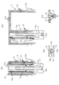
図3に示すように、油圧シリンダ5は、最下段のマスト41の底壁41aに下端が軸支されたシリンダロッド5aと、シリンダロッド5aの上部が挿入されたシリンダチューブ5bとを有している。
マスト同士の係脱機構とマストと油圧シリンダとの係脱機構とを説明する。以下に説明する係脱機構と当該係脱機構と油圧シリンダ5とを用いたマスト集合体4の伸縮機構の詳細は、特許第3212467号、特許第4263280号等に開示されたものと同様である。
シリンダチューブ5bには、図示しない油圧シリンダによって水平方向に進退駆動される係合部材8と、図示しない他の油圧シリンダによって水平方向に進退駆動される一対のピン9とが取り付けられている。係合部材8とピン9とは、周方向に90度間隔を隔てて配設されている。
最下段のマスト41を除く各段のマスト41の下端近傍部に、バネで水平方向外側へ付勢されたピン10が取り付けられている。
最上段のマスト41を除く各段のマスト41の下端近傍部に、直上段のマスト41のピン10が嵌入可能な孔11が形成され、最上段のマスト41を除く各段のマスト41の上端近傍部に、直上段のマスト41のピン10が嵌入可能な孔12が形成されている。
最下段のマスト41を除く各段のマスト41の下端近傍部に、シリンダチューブ5bに取り付けられた一対のピン9が嵌入可能な一対の孔13が形成されている。
As shown in FIG. 3, the
The engagement / disengagement mechanism between the masts and the engagement / disengagement mechanism between the mast and the hydraulic cylinder will be described. The details of the engagement / disengagement mechanism described below and the expansion / contraction mechanism of the
An engagement member 8 that is driven back and forth in a horizontal direction by a hydraulic cylinder (not shown) and a pair of
A
A hole 11 into which the
A pair of
帆走機構2の作動を説明する。
非帆走時には、図3に示すように、油圧シリンダ5は収縮している。マスト集合体4を構成するマスト41間の上下方向重畳量が最大値になってマスト集合体4は収縮しており、硬帆集合体3を構成する硬帆31間の上下方向重畳量が最大値になって硬帆集合体3は縮帆している。
シリンダチューブ5に取り付けられた係合部材8が進出位置に在って、最上段のマスト41に取り付けられたピン10に係合している。
シリンダチューブ5に取り付けられた一対のピン9が進出位置に在って、最上段のマスト41の一対の孔13に嵌入し、最上段のマスト41をシリンダチューブ5に固定している。
最下段のマスト41を除く各段のマスト41に取り付けられたピン10が、バネの付勢力を受けて直下段のマスト41の孔11に嵌入し、最下段のマスト41を除く各段のマスト41を直下段のマスト41に固定している。
The operation of the
When not sailing, the
The engaging member 8 attached to the
A pair of
The
帆走時には、係合部材8が後退位置へ移動し、最上段のマスト41に取り付けられたピン10が、バネの付勢力に抗して直下段のマスト41に形成された孔11から離脱して、最上段のマスト41と直下段のマスト41との固定状態を解除する。
図4に示すように、油圧シリンダ5が伸長してシリンダチューブ5bが上方へ移動し、シリンダチューブ5bに固定された最上段のマスト41が上方へ移動し、頂壁31aを介して最上段のマスト41に連結されたす最上段の硬帆31が上方へ移動する。
シリンダチューブ5に取り付けられた係合部材8が進出位置へ移動し、最上段のマスト41に取り付けられたピン10が、直下段のマスト41に形成された孔12に嵌入して、最上段のマスト41を直下段のマスト41に固定する。
During sailing, the engaging member 8 moves to the retracted position, and the
As shown in FIG. 4, the
The engaging member 8 attached to the
シリンダチューブ5に取り付けられた一対のピン9が後退位置へ移動し、最上段のマスト41の一対の孔13から離脱して、最上段のマスト41とシリンダチューブ5との固定状態を解除する。
油圧シリンダ5が収縮してシリンダチューブ5bが下方へ移動する。最上段のマスト41に取り付けられたピン10は、バネの付勢力を受けて直下段のマスト41に形成された孔12に嵌入した状態を維持するので、最上段のマスト41と直下段のマスト41との固定状態は維持される。進出位置に在る係合部材8と最上段のマスト41に取り付けられたピン10との係合状態は、シリンダチューブ5bの下方への移動によって解除される。従って、シリンダチューブ5bは支障なく下方へ移動することができる。
進出位置に在る係合部材8が、上から2段目のマスト41に取り付けられたピン10と係合すると、シリンダチューブ5bが停止する。
The pair of
The
When the engaging member 8 at the advanced position engages with the
係合部材8が後退位置へ移動し、上から2段目のマスト41に取り付けられたピン10が、バネの付勢力に抗して直下段のマスト41に形成された孔11から離脱し、上から2段目のマスト41と直下段のマスト41との固定状態を解除する。
シリンダチューブ5に取り付けられた一対のピン9が進出位置へ移動し、上から2段目のマスト41の一対の孔13に嵌入し、上から2段目のマスト41をシリンダチューブ5に固定する。
油圧シリンダ5が伸長してシリンダチューブ5bが上方へ移動し、シリンダチューブ5bに固定された上から2段目のマスト41が上方へ移動し、頂壁31aを介して上から2段目のマスト41に連結されたす上から2段目の硬帆31が上方へ移動する。
シリンダチューブ5に取り付けられた係合部材8が進出位置へ移動し、上から2段目のマスト41に取り付けられたピン10が、直下段のマスト41に形成された孔12に嵌入して、上から2段目のマスト41を直下段のマスト41に固定する。
シリンダチューブ5に取り付けられた一対のピン9が後退位置へ移動し、上から2段目のマスト41の一対の孔13から離脱して、上から2段目のマスト41とシリンダチューブ5との固定状態を解除する。
油圧シリンダ5が収縮してシリンダチューブ5bが下方へ移動する。
進出位置に在る係合部材8が、上から3段目のマスト41に取り付けられたピン10と係合すると、シリンダチューブ5bが停止する。
The engaging member 8 moves to the retracted position, and the
The pair of
The
The engaging member 8 attached to the
The pair of
The
When the engaging member 8 at the advanced position engages with the
上述の動作が繰り返されて、マスト集合体4を構成するマスト41間の上下方向重畳量が最小値まで減少してマスト集合体4が伸長し、硬帆集合体3を構成する硬帆31間の上下方向重畳量が最小値まで減少して、硬帆集合体3が展帆する。
モータ・歯車装置6が作動してポスト7が上下に延在する中心軸線回りに回転し、硬帆集合体3を風に対して最適方向へ差し向ける。
双胴式の海洋調査船Aは、プロペラ推進器1の推力に加えて帆走機構2の硬帆集合体3が発生させた推力をも用いて航行する。
By repeating the above-described operation, the amount of overlap in the vertical direction between the
The motor / gear device 6 is actuated to rotate the post 7 around the central axis extending vertically, thereby directing the
The catamaran marine research ship A navigates using the thrust generated by the
展帆した硬帆集合体3を縮帆する際には、展帆時の手順と逆の手順で、最下段のマスト41を除く各段のマスト41を直下段のマスト41へ向けて下降させ、マスト集合体4を構成するマスト41間の上下方向重畳量を最大値まで増加させ、硬帆集合体3を構成する硬帆31間の上下方向重畳量を最大値まで増加させる。
When the expanded
海洋調査船Aにおいては、上下に整列して積層した複数の翼断面筒体の硬帆31から成る硬帆集合体3を展縮により高さ可変としたので、硬帆集合体3は橋梁下の航行の障害にならない。
海洋調査船Aにおいては、同一段の硬帆31の上端部とマスト41上端部とを連結して、マスト41が硬帆31を支える構造としたので、大寸法の硬帆31を軽量の樹脂で形成し、硬帆31に比べて小寸法のマスト41を鋼などの高強度素材で形成することにより、帆走機構2の軽量化と適正な強度とを実現することが可能である。
硬帆31の筒体上端部に設けた頂壁31aと、硬帆31の筒体下端部に設けたフレーム31bとは、硬帆31の翼断面形状を維持する部材として効果的に機能する。硬帆31の上端部とマスト41の上端部とを連結する頂壁31aを翼断面形状維持部材として利用することにより、筒体上部に翼断面形状維持部材を別途設ける必要がなくなり、部材数が減少する。筒体下端部の翼断面形状維持部材である硬帆外周面を取り巻くフレーム31bには、硬帆集合体3の展縮を妨げない利点がある。
In the oceanographic survey ship A, the height of the
In the oceanographic survey ship A, the upper end of the
The
図3(d)に示すように、最下段の硬帆31を除く各段の硬帆31の内面に、周方向に間隔を隔てて複数の上下に延在するレール14aを固定し、直下段の硬帆31の外面上部に、周方向に間隔を隔てて複数の台車部材14bを固定し、ボールベアリング14cを介してレール14aに台車部材14bを係合させても良い。レール14aと台車部材14bとボールベアリング14cとで形成される案内部材14が、最下段の硬帆31を除く各段の硬帆31を直下段の硬帆31に対して上下方向に案内するので、硬帆集合体3の展縮動作がスムーズになる。案内部材の構成は、上記のものに限定されない。
図5(a)に示すように、最上段のマスト41を除く各段のマスト41の下部内面と直上のマスト41の上部外面とを油圧ジャッキ15を介して連結し、4個の油圧ジャッキ15を駆動して、マスト集合体4を伸縮させても良い。
図5(b)に示すように、最上段のマスト41を除く各段のマスト41の内面と直上のマスト41の外面とをラック・ピニオン16を介して連結し、ピニオンを駆動するモータを設置して、マスト集合体4を伸縮させても良い。
図5(c)に示すように、最上段のマスト41を除く各段のマスト41と直上のマスト41との間に巻き上げ機17を設置して、マスト集合体4を伸縮させても良い。
図5(d)に示すように、重畳する硬帆31の頂壁31a間に、パンタグラフ18とパンタグラフを昇降駆動する油圧ジャッキ19とを設置して、マスト集合体4を伸縮させても良い。
マスト集合体4の伸縮機構は上述の構成に限定されない。マスト集合体4を伸縮でき且つ伸長状態に保持できるものであれば良い。
帆走機構2を、各種商船、客船等種々の船に搭載しても良い。
As shown in FIG. 3 (d), a plurality of upper and lower rails 14a extending at intervals in the circumferential direction are fixed to the inner surface of each stage of the hard sails 31 except for the lowermost stage
As shown in FIG. 5A, the lower inner surface of the
As shown in FIG. 5B, a motor for driving the pinion is installed by connecting the inner surface of the
As shown in FIG. 5C, the
As shown in FIG. 5 (d), the
The expansion and contraction mechanism of the
The
本発明は、船舶に広く利用可能である。 The present invention is widely applicable to ships.
A 海洋調査船
1 プロペラ推進器
2 帆走機構
3 硬帆集合体
31 硬帆
4 マスト集合体
41 マスト
5 油圧ジャッキ
6 モータ・歯車装置
A Ocean Research Vessel 1
Claims (3)
Priority Applications (5)
| Application Number | Priority Date | Filing Date | Title |
|---|---|---|---|
| JP2010065143A JP5318008B2 (en) | 2010-03-19 | 2010-03-19 | Sailing ship |
| EP11157174.1A EP2366621B1 (en) | 2010-03-19 | 2011-03-07 | Sailing Ship |
| US13/051,841 US8413598B2 (en) | 2010-03-19 | 2011-03-18 | Sailing ship |
| KR1020110024255A KR20110105727A (en) | 2010-03-19 | 2011-03-18 | Sailing ship |
| CN2011100659871A CN102190078A (en) | 2010-03-19 | 2011-03-18 | Sailing ship |
Applications Claiming Priority (1)
| Application Number | Priority Date | Filing Date | Title |
|---|---|---|---|
| JP2010065143A JP5318008B2 (en) | 2010-03-19 | 2010-03-19 | Sailing ship |
Publications (2)
| Publication Number | Publication Date |
|---|---|
| JP2011195059A JP2011195059A (en) | 2011-10-06 |
| JP5318008B2 true JP5318008B2 (en) | 2013-10-16 |
Family
ID=44235953
Family Applications (1)
| Application Number | Title | Priority Date | Filing Date |
|---|---|---|---|
| JP2010065143A Active JP5318008B2 (en) | 2010-03-19 | 2010-03-19 | Sailing ship |
Country Status (5)
| Country | Link |
|---|---|
| US (1) | US8413598B2 (en) |
| EP (1) | EP2366621B1 (en) |
| JP (1) | JP5318008B2 (en) |
| KR (1) | KR20110105727A (en) |
| CN (1) | CN102190078A (en) |
Cited By (1)
| Publication number | Priority date | Publication date | Assignee | Title |
|---|---|---|---|---|
| EP3511601B1 (en) * | 2011-03-21 | 2023-10-11 | Engineered Controls International, LLC | Rapid-connect coupler with vent-stop |
Families Citing this family (20)
| Publication number | Priority date | Publication date | Assignee | Title |
|---|---|---|---|---|
| CN102407928B (en) * | 2011-10-24 | 2014-08-13 | 重庆长航东风船舶工业公司 | Hydraulic lift chimney for ship |
| CA2880376C (en) * | 2012-06-29 | 2019-02-19 | Windship Technology Limited | Aerofoil sail |
| DK2925600T3 (en) * | 2012-11-28 | 2019-04-08 | Robert Reginald Bray | A WINGLE AND USE THEREOF |
| CN103253351B (en) * | 2013-05-14 | 2015-12-02 | 上海珐伊玻璃钢船艇有限公司 | Sailing boat |
| CN103538710B (en) * | 2013-11-04 | 2015-09-30 | 上海海事大学 | A kind of adjustable for height segment type sail |
| JP6439260B2 (en) * | 2014-03-18 | 2018-12-19 | 株式会社タダノ | Telescopic hard sail control method and control device for hard sail ship |
| JP2015205525A (en) * | 2014-04-17 | 2015-11-19 | 株式会社タダノ | Hard sail ship |
| CN104118551B (en) * | 2014-08-11 | 2017-02-15 | 中国船舶重工集团公司第七○二研究所 | Automatic retractable type combined wind blade device |
| JP6373156B2 (en) * | 2014-10-14 | 2018-08-15 | 株式会社大内海洋コンサルタント | Container side windshield device and side windshield method for container ship |
| CN104890845B (en) * | 2015-06-23 | 2017-04-05 | 江苏科技大学 | Horizontal foldable automatic deploying and retracting aerofoil profile sail |
| CN104973217A (en) * | 2015-07-20 | 2015-10-14 | 中国船舶重工集团公司第七○二研究所 | Layout structure of upper-layer construction of sailboat |
| ES2557518B1 (en) * | 2015-08-24 | 2016-10-19 | Andrés CHACON FIDALGO | Lifting and lowering system for wing sails and corresponding sails |
| CN105539795A (en) * | 2015-12-21 | 2016-05-04 | 中国船舶重工集团公司第七○二研究所 | Sailing boat with layered adjustable hard sail surfaces |
| FR3058386B1 (en) * | 2016-11-08 | 2019-06-28 | Ayro | VELIC PROPULSION SHIP. |
| CN107878720B (en) * | 2017-11-09 | 2019-06-04 | 沈阳工程学院 | A kind of retractable symmetrical airfoil wind sail device |
| EP3891063A1 (en) | 2018-12-06 | 2021-10-13 | Ayro | Ship with sail propulsion |
| DE202019102941U1 (en) | 2019-02-18 | 2019-06-05 | Becker Marine Systems Gmbh | Fixed sails for watercraft, in particular for large ships, and watercraft with rigid sails |
| KR102596174B1 (en) * | 2019-09-23 | 2023-10-30 | 삼성중공업 주식회사 | Apparatus for propulsion |
| DE102021213123A1 (en) | 2021-10-08 | 2023-04-13 | Detlev Löll & Uwe Reum Wingsails GbR (Dipl.-Ing. Uwe Reum, 99817 Eisenach) | Wing sail, watercraft and method of operating a wing sail |
| CN115027653A (en) * | 2022-07-15 | 2022-09-09 | 上海外高桥造船有限公司 | Lifting type wind power navigation aid device and ship |
Family Cites Families (16)
| Publication number | Priority date | Publication date | Assignee | Title |
|---|---|---|---|---|
| JPS57198194A (en) * | 1981-05-28 | 1982-12-04 | Nippon Kokan Kk <Nkk> | Furling and unfurling system for marine canvas |
| JPS57198195A (en) * | 1981-05-28 | 1982-12-04 | Nippon Kokan Kk <Nkk> | Marine canvas rig |
| JPS5828098U (en) * | 1981-08-17 | 1983-02-23 | 日立造船株式会社 | sailing ship |
| JPS61200091A (en) * | 1985-02-28 | 1986-09-04 | Osaka Sosenjo:Kk | Hard sail device for ship |
| US4685410A (en) * | 1985-04-08 | 1987-08-11 | Fuller Robert R | Wing sail |
| IT1231705B (en) * | 1989-09-15 | 1991-12-20 | Giorgio Magrini | SAIL STRUCTURE SO-CALLED AT WING. |
| JPH03212467A (en) | 1990-01-17 | 1991-09-18 | Toppan Printing Co Ltd | Acrylic coating material and its use |
| JPH04263280A (en) | 1991-02-18 | 1992-09-18 | Canon Inc | Fixing heater for image forming device |
| EP0511419B1 (en) * | 1991-04-29 | 1995-01-25 | Wilhelm Brinkmann | Wingsail |
| DE4344795A1 (en) * | 1993-12-28 | 1995-06-29 | Liebherr Werk Ehingen | Mobile crane with a telescopic boom |
| US5517940A (en) * | 1995-05-08 | 1996-05-21 | Beyer; Jay R. | Variable width multi-hulled boat with telescoping mast |
| JP4263280B2 (en) * | 1998-11-24 | 2009-05-13 | 株式会社タダノ | Mobile crane boom telescopic mechanism |
| US6526901B2 (en) * | 2001-03-30 | 2003-03-04 | Camillo M. Iacoboni | Retractable mast for sailboats |
| JP2005280533A (en) | 2004-03-30 | 2005-10-13 | Sumitomo Heavy Industries Marine & Engineering Co Ltd | Rig merchant ship |
| JP2006111026A (en) | 2004-10-12 | 2006-04-27 | Fukushima Zosen Tekkosho:Kk | Telescopic mast device |
| JP5137628B2 (en) * | 2008-03-08 | 2013-02-06 | 株式会社大内海洋コンサルタント | Sailing ship with hard sails |
-
2010
- 2010-03-19 JP JP2010065143A patent/JP5318008B2/en active Active
-
2011
- 2011-03-07 EP EP11157174.1A patent/EP2366621B1/en active Active
- 2011-03-18 US US13/051,841 patent/US8413598B2/en active Active
- 2011-03-18 KR KR1020110024255A patent/KR20110105727A/en active Search and Examination
- 2011-03-18 CN CN2011100659871A patent/CN102190078A/en active Pending
Cited By (1)
| Publication number | Priority date | Publication date | Assignee | Title |
|---|---|---|---|---|
| EP3511601B1 (en) * | 2011-03-21 | 2023-10-11 | Engineered Controls International, LLC | Rapid-connect coupler with vent-stop |
Also Published As
| Publication number | Publication date |
|---|---|
| US20110226172A1 (en) | 2011-09-22 |
| KR20110105727A (en) | 2011-09-27 |
| EP2366621A3 (en) | 2014-06-18 |
| EP2366621B1 (en) | 2017-01-25 |
| EP2366621A2 (en) | 2011-09-21 |
| CN102190078A (en) | 2011-09-21 |
| US8413598B2 (en) | 2013-04-09 |
| JP2011195059A (en) | 2011-10-06 |
Similar Documents
| Publication | Publication Date | Title |
|---|---|---|
| JP5318008B2 (en) | Sailing ship | |
| US7581507B2 (en) | Launch and recovery devices for water vehicles and methods of use | |
| CN102712350B (en) | Offshore wind turbines is installed | |
| US8117978B2 (en) | Sailing ship equipped with a hard sail | |
| JP5826948B2 (en) | Thruster system and ship including the same | |
| US9139256B2 (en) | Improvements relating to masts | |
| KR101865164B1 (en) | Separable type offshore structures installation vessels and method of operating the same | |
| JP2012240540A (en) | Ship having square sail formed with hard sail, and method for accommodating and deploying square sail | |
| KR20120119335A (en) | A vessel with retractable thruster | |
| JP2012240539A (en) | Ship having square sail formed with hard sail, and method for accommodating and deploying square sail | |
| US11168666B1 (en) | Jack-up platform with receiving space for a barge and method for offshore installation of a wind turbine | |
| JP2018108790A (en) | Lifting device for boat, ship and lifting method for boat | |
| JP6001750B2 (en) | Ship with side sail formed by hard sail and method for storing and deploying side sail | |
| JP2011098669A (en) | Sailing device and sailing trading vessel | |
| JP2014080051A (en) | Sail device of craft, sail motorboat, and sailing method for craft | |
| JP6964339B2 (en) | How to hold the onboard boat using the boat davit and the onboard boat holding mechanism | |
| KR101556268B1 (en) | Method for installing canister guide apparatus | |
| KR101487678B1 (en) | Canister-type thruster | |
| KR102479127B1 (en) | Semi-submersible marine structure | |
| KR101475205B1 (en) | Canister-type thruster | |
| KR101487675B1 (en) | Canister-type thruster | |
| KR101475199B1 (en) | Canister-type thruster and lifting method for canister | |
| KR101487677B1 (en) | Guiding device for canister-type thruster | |
| KR101516560B1 (en) | Method for installing canister guide apparatus | |
| KR101540303B1 (en) | Canister-type thruster |
Legal Events
| Date | Code | Title | Description |
|---|---|---|---|
| A621 | Written request for application examination |
Free format text: JAPANESE INTERMEDIATE CODE: A621 Effective date: 20120527 |
|
| A977 | Report on retrieval |
Free format text: JAPANESE INTERMEDIATE CODE: A971007 Effective date: 20130619 |
|
| TRDD | Decision of grant or rejection written | ||
| A01 | Written decision to grant a patent or to grant a registration (utility model) |
Free format text: JAPANESE INTERMEDIATE CODE: A01 Effective date: 20130702 |
|
| A61 | First payment of annual fees (during grant procedure) |
Free format text: JAPANESE INTERMEDIATE CODE: A61 Effective date: 20130709 |
|
| R150 | Certificate of patent or registration of utility model |
Ref document number: 5318008 Country of ref document: JP Free format text: JAPANESE INTERMEDIATE CODE: R150 Free format text: JAPANESE INTERMEDIATE CODE: R150 |
|
| R250 | Receipt of annual fees |
Free format text: JAPANESE INTERMEDIATE CODE: R250 |
|
| R250 | Receipt of annual fees |
Free format text: JAPANESE INTERMEDIATE CODE: R250 |
|
| R250 | Receipt of annual fees |
Free format text: JAPANESE INTERMEDIATE CODE: R250 |
|
| R250 | Receipt of annual fees |
Free format text: JAPANESE INTERMEDIATE CODE: R250 |
|
| S111 | Request for change of ownership or part of ownership |
Free format text: JAPANESE INTERMEDIATE CODE: R313117 |
|
| R250 | Receipt of annual fees |
Free format text: JAPANESE INTERMEDIATE CODE: R250 |
|
| R350 | Written notification of registration of transfer |
Free format text: JAPANESE INTERMEDIATE CODE: R350 |
|
| R250 | Receipt of annual fees |
Free format text: JAPANESE INTERMEDIATE CODE: R250 |
|
| R250 | Receipt of annual fees |
Free format text: JAPANESE INTERMEDIATE CODE: R250 |
|
| R250 | Receipt of annual fees |
Free format text: JAPANESE INTERMEDIATE CODE: R250 |