JP5317267B2 - Wafer mounting device - Google Patents
Wafer mounting device Download PDFInfo
- Publication number
- JP5317267B2 JP5317267B2 JP2008291870A JP2008291870A JP5317267B2 JP 5317267 B2 JP5317267 B2 JP 5317267B2 JP 2008291870 A JP2008291870 A JP 2008291870A JP 2008291870 A JP2008291870 A JP 2008291870A JP 5317267 B2 JP5317267 B2 JP 5317267B2
- Authority
- JP
- Japan
- Prior art keywords
- wafer
- frame
- dicing tape
- dicing
- air
- Prior art date
- Legal status (The legal status is an assumption and is not a legal conclusion. Google has not performed a legal analysis and makes no representation as to the accuracy of the status listed.)
- Expired - Fee Related
Links
Images


Landscapes
- Container, Conveyance, Adherence, Positioning, Of Wafer (AREA)
- Dicing (AREA)
Abstract
Description
本発明は、ウエハをダイシングテープを介してダイシングフレームにマウントするウエハのマウント装置に関する。さらに詳しくは、その一面が凹凸形状に形成されたウエハをダイシングテープを介してダイシングフレームにマウントするウエハのマウント装置に関する。 The present invention relates to a wafer mounting apparatus for mounting a wafer on a dicing frame via a dicing tape. More specifically, the present invention relates to a wafer mounting apparatus for mounting a wafer having one surface thereof having an uneven shape on a dicing frame via a dicing tape.
従来より、一般的な半導体の製造工程においては、ウエハのパターン形成面(表面)に保護テープを貼り付けた後、前記ウエハの裏面を研削して薄厚化し、その後、保護テープに貼り付けられた状態のウエハをダイシングテープを介してダイシングフレームにマウントし、前記保護テープを剥離テープ等で剥離した後、ダイシングしてチップ化することが行われている。 Conventionally, in a general semiconductor manufacturing process, after a protective tape is applied to the pattern forming surface (front surface) of a wafer, the back surface of the wafer is ground and thinned, and then applied to the protective tape. A wafer in a state is mounted on a dicing frame via a dicing tape, the protective tape is peeled off with a peeling tape or the like, and then diced into chips.
ところで、ダイオード、トランジスタ等の単機能半導体(ディスクリート)用のウエハの製造工程においては、ウエハ裏面に電極を形成するため、ウエハ裏面に金属蒸着等で金属薄膜を形成する工程が行われている。このようにウエハ裏面に金属薄膜を形成するには、スパッタリングや蒸着等の高温での処理が必要であり、ウエハのパターン形成面に貼り付けられた保護テープは処理温度に耐えることができないため剥離する必要がある。また、低温で処理を行う場合であっても、保護テープに使用されている粘着剤等の不純物の混入の面から保護テープが蒸着等の処理の前に剥離されている。このような単機能半導体用のウエハはその後、ダイシングテープを介してダイシングフレームにマウントされ、ダイシング工程を経てチップ化される。 By the way, in a manufacturing process of a wafer for a single function semiconductor (discrete) such as a diode or a transistor, a process of forming a metal thin film on the back surface of the wafer by metal deposition or the like is performed in order to form an electrode on the back surface of the wafer. In order to form a metal thin film on the backside of the wafer in this way, processing at a high temperature such as sputtering or vapor deposition is required, and the protective tape attached to the pattern forming surface of the wafer cannot withstand the processing temperature, so that it is peeled off. There is a need to. Further, even when the treatment is performed at a low temperature, the protective tape is peeled off before the treatment such as vapor deposition from the side where impurities such as an adhesive used for the protective tape are mixed. Such a wafer for a single function semiconductor is then mounted on a dicing frame via a dicing tape, and is formed into a chip through a dicing process.
しかし最近の携帯機器の小型化の要請からウエハの厚みは100μmを切り、50μm以下のものも使用されるようになってきており、上記のように保護テープを剥離したウエハは取扱いが非常に困難になってきている。 However, due to recent demands for miniaturization of portable devices, the thickness of wafers has been reduced to less than 100 μm, and those with a thickness of 50 μm or less are also being used. It is becoming.
そこで、ウエハの反りや欠けを防止し、取扱いを容易にすべく、ウエハ裏面の外周にリング状のリブを残し、内周部分が研削された凹凸形状のウエハも出てきている(例えば特許文献1)。 Therefore, in order to prevent the wafer from warping and chipping and to facilitate handling, an uneven wafer having a ring-shaped rib on the outer periphery of the wafer back surface and an inner peripheral portion ground has also come out (for example, Patent Documents). 1).
本方法によればウエハの外周のリング状のリブは内周部分の厚みに比べ厚く構成されており、外周部分の欠けやウエハの反りを防止できるとともに取扱いが容易となる。 According to this method, the ring-shaped ribs on the outer periphery of the wafer are configured to be thicker than the thickness of the inner peripheral portion, so that chipping of the outer peripheral portion and warpage of the wafer can be prevented and handling becomes easy.
上記のウエハの形成方法について、図24(a)乃至(g)及び図25に基づいて説明する。 The wafer forming method will be described with reference to FIGS. 24 (a) to 24 (g) and FIG.
図24(a)のように、まず、表面に回路パターンが形成されたウエハ1が準備され、続いて図24(b)のようにウエハ1のパターン形成面に保護テープが貼り付けられる。なお、図24(a)乃至(g)においては、説明の便宜上、ウエハ1のパターン形成面(表面)が図示下側となるように描いている。
As shown in FIG. 24A, first, a
続いて図24(c)のように表面に保護テープ2が貼り付けられたウエハ1の裏面の外周にリング状のリブを残して内周部分が所定の厚みに研削され、外周リブ62と仕上げ研磨面61が形成された凹凸形状のウエハ1が形成される。
Subsequently, as shown in FIG. 24C, the inner peripheral portion is ground to a predetermined thickness, leaving a ring-shaped rib on the outer periphery of the back surface of the
図25のように、内周部分の研削は、通常、粗めの砥石でウエハ1の内周部分をある程度研削して粗削りした後、目の細かい砥石で仕上げ研磨が行われる。このため、ウエハ1の内周研削部分には研削途中での砥石の変更により、粗削り面63(厚みd2は100μm程度、幅L2は0.5〜0.8mm程度)と仕上げ研磨面61(厚みd3は例えば50μm)が形成される。なお、リング状に形成された外周リブ62の厚みd1は例えば725μmであり、幅L1は例えば2.5mmである。また、保護テープ2の厚みd4は例えば130μmである。
As shown in FIG. 25, the inner peripheral portion is usually ground by grinding the inner peripheral portion of the
続いて図24(d)のように保護テープ2が剥離テープ等で剥離され、図24(e)のようにウエハ1裏面に蒸着又はスパッタリング等で金属膜60が形成され、続いて図24(f)のように金属膜60が形成されたウエハ1は再度パターン形成面に保護テープ2が貼り付けられ、図24(g)のようにウエハ1はダイシングテープ4を介してダイシングフレーム3にマウントされる。前記マウントされたウエハ1は表面の保護テープ2が剥離され、ダイシング工程に供される。
Subsequently, the
上記ダイシングフレーム3へのウエハ1のマウントは、ウエハ1裏面の凹凸形状面に対して行なう必要があり、例えば図23(a)及び(b)のように行われている。
The mounting of the
図23(a)のように貼付テーブル71上にウエハ1をその凹凸形状面を上にして載置保持しておき、貼付テーブル71の外周外側全域に設けられたフレーム台72上にダイシングテープ4の貼り付けられたダイシングフレーム3を傾斜状態で保持する。
As shown in FIG. 23A, the
次に図示矢印のように貼付ローラ74でダイシングテープ4をウエハ1に押圧していくことでフレーム台72が上方に付勢されたバネ75に抗して水平となるように揺動し、ダイシングテープ4がウエハ1に貼り付けられる。水平状態となったフレーム台72は、適宜な機構で水平状態で固定される。
Next, the
図23(b)のようにウエハ1がダイシングフレーム3にマウントされ、貼付ローラ74が初期位置に復帰する。
As shown in FIG. 23B, the
このように、ウエハ1裏面の凹凸形状面が上面となるようにウエハ1を貼付テーブル71上に保持し、貼付ローラ74でダイシングテープ4をウエハ1に押圧しながら貼り付ける方法では、ウエハ1の内周研削面を完全には押圧できず、特に外周リブ62を残して、内周部分が研削されたウエハ1では外周リブ62と内周研削部分との境界で気泡が発生する問題があった。
In this way, in the method in which the
そこで、これを解決すべく、外周リブを残して、内周部分が研削されたウエハに真空中で前記外周リブの内側に内嵌する部材でダイシングテープをウエハに押圧して貼り付けたり、ウエハの内周研削部の中央から外側に向けてブラシでらせん状にダイシングテープを押圧して貼り付けることが行なわれている(例えば特許文献2)。 Therefore, in order to solve this problem, the outer peripheral rib is left and the dicing tape is pressed and pasted on the wafer with a member fitted inside the outer peripheral rib in a vacuum on the wafer whose inner peripheral portion is ground, A dicing tape is pressed and pasted in a spiral shape with a brush from the center to the outside of the inner peripheral grinding portion (for example, Patent Document 2).
また、上記以外にも配線の取り回しを簡素化させるために裏面にバンプ電極を設けたウエハをダイシングテープを介してダイシングフレームにマウントし、その後、ダイシングすることも行なわれている。
しかし、上記特許文献2のようにウエハ内周研削部分へ内嵌部材でダイシングテープを押圧する方法は、ウエハの外周リブの内径に合わせて、内嵌部材が内嵌できるように内嵌部材の大きさを精密に調整しなければならず、内嵌部材が外周リブの内径より若干小さく形成されているので、ウエハ内周研削部と外周リブとの境界部分を完全には押圧できずに気泡が発生する問題がある。
However, the method of pressing the dicing tape with the inner fitting member to the inner peripheral grinding portion of the wafer as in the above-mentioned
また、内嵌部材がウエハの外周リブの内径より大きく形成されている場合は、内嵌部材と外周リブとが干渉し、ウエハが破損したり、気泡が発生したりする問題がある。 Further, when the inner fitting member is formed larger than the inner diameter of the outer peripheral rib of the wafer, there is a problem that the inner fitting member and the outer peripheral rib interfere with each other and the wafer is damaged or bubbles are generated.
また、内嵌部材とウエハの外周リブの内径が同一径であっても、内嵌時に精密な位置決めが必要であり、制御が複雑となったり、図25のように内周研削部と外周リブ62との境界部分には内周研削時に発生する粗削り面63と仕上げ研磨面61との段差があり、ダイシングテープを全体に均一に押圧することができない問題がある。
Further, even if the inner diameter of the inner fitting member and the outer peripheral rib of the wafer is the same diameter, precise positioning is required at the time of the inner fitting, and the control becomes complicated, or the inner peripheral grinding portion and the outer peripheral rib as shown in FIG. There is a step between the roughened
さらに、ブラシでウエハ内周研削部の中央から外側に向けてダイシングテープをらせん状に押圧する方法は、らせん運動によりダイシングテープが順次外側に向けて押圧されていくため、ダイシングテープが回転方向に引き伸ばされてダイシングテープにしわが入る問題もある。 Furthermore, the method of spirally pressing the dicing tape from the center to the outside of the wafer inner peripheral grinding part with a brush is because the dicing tape is sequentially pressed outward by the spiral motion, so that the dicing tape is rotated in the rotation direction. There is also a problem that wrinkles of the dicing tape are stretched.
また、ダイシングテープをウエハ裏面の凹凸形状に沿って貼り付けるには、押圧部材の表面がその剛性に負けない程度の硬度が必要であり、特にダイシングテープはウエハを支持するだけの剛性を有しているため、これに打ち勝つ程度の硬度が必要となる。 In addition, in order to attach the dicing tape along the uneven shape on the back surface of the wafer, the surface of the pressing member needs to have a hardness that does not lose its rigidity. In particular, the dicing tape has a rigidity that supports the wafer. Therefore, a hardness that can overcome this is required.
しかし、上記特許文献2のように内嵌部材の硬度を高めると、ウエハと内嵌部材との接触時にウエハを破損したり、また、位置決め精度が悪いとウエハの外周リブと内嵌部材が接触してウエハを破損する場合がある。
However, if the hardness of the inner fitting member is increased as in
また、特許文献2のようにブラシを中央部から外周に向けてらせん状に押圧して貼り付ける場合は、ブラシをダイシングテープの剛性に打ち勝つ硬度とすると、ダイシングテープを傷つけたり、ウエハの外周リブを破損したりする問題がある。逆に、ウエハ裏面の凹凸形状に追従するように内嵌部材又はブラシを柔軟にすればダイシングテープの剛性に負け、ウエハ裏面の凹凸形状に沿ってダイシングテープを密着させることが困難となる問題がある。
Also, as in
このため、ウエハ内周研削部と外周リブとの高低差により、ダイシングテープがウエハ内周研削部と外周リブの内壁に完全に密着して貼り付けられておらず、内周研削部と外周リブの境界部分での接着不良により、ダイシング時にチップが飛散する問題がある。また、ダイシングテープの剛性に打ち勝つように接着を行わなければ、経時的にダイシングテープがその剛性により剥がれ、気泡が広がっていく問題がある。 Therefore, due to the difference in height between the wafer inner peripheral grinding part and the outer peripheral rib, the dicing tape is not completely adhered and adhered to the inner wall of the wafer inner peripheral grinding part and the outer peripheral rib. There is a problem that chips are scattered during dicing due to poor adhesion at the boundary portion. In addition, unless bonding is performed so as to overcome the rigidity of the dicing tape, there is a problem in that the dicing tape is peeled off due to the rigidity over time, and bubbles are spread.
上記は特許文献2のように内嵌部材を加熱してダイシングテープを軟化させて貼り付けた場合においても、内嵌部材とウエハの凹凸を完全に密着させることが困難であるので、このままダイシングを行なうと、チップがダイシングテープから剥離して飛散する問題がある。
Even when the inner fitting member is heated and the dicing tape is softened and pasted as in
そこで本発明の目的は、凹凸形状に形成されたウエハ裏面の凹凸形状に沿ってしわや気泡無くダイシングテープを貼り付けるとともに、経時的にもダイシングテープが剥がれないようにし、ダイシング時にチップを飛散させないウエハのマウント装置を提供することにある。 Accordingly, an object of the present invention is to apply a dicing tape without wrinkles or bubbles along the uneven shape on the back surface of the wafer formed into an uneven shape, and to prevent the dicing tape from peeling over time, so that chips are not scattered during dicing. An object of the present invention is to provide a wafer mounting apparatus.
また、ウエハ裏面にバンプ電極等が設けられ凹凸形状に形成されたウエハの凹凸形状に沿って埋め込み良くダイシングテープを貼り付け、ダイシング時にチップを飛散させないウエハのマウント装置を提供することにある。 It is another object of the present invention to provide a wafer mounting apparatus in which a bump electrode or the like is provided on the back surface of a wafer and a dicing tape is affixed well along the uneven shape of the wafer formed into an uneven shape so that chips are not scattered during dicing.
そこで請求項1の発明は、その一面が凹凸形状に形成されたウエハをダイシングテープを介してダイシングフレームにマウントするウエハのマウント装置において、互いに昇降可能に支持された上下一対の上部枠体と下部枠体とからなり、これら上部枠体と下部枠体の密着により、その内部を密閉状態になるように構成するとともに、前記上部枠体には、その下面に弾性変形可能な材質からなる通気性部材を装着して、この上部枠体に穿設された通気孔を通して前記通気性部材全域に圧縮空気を導入するように構成し、前記下部枠体には、その上面にウエハを載置保持するようにテーブル面を形成し、前記下部枠体の外周外側全域にはダイシングテープが貼り付けられたダイシングフレームを保持するフレーム台が設けられており、前記上部枠体の下降動で前記通気性部材を介してダイシングテープを押し下げ、然る後、下部枠体の上昇動により、通気性部材を弾性変形させながら該下部枠体のテーブル面に保持されたウエハの凹凸形状に沿ってダイシングテープを押圧するとともに、これら上下枠体の密着により、その内部を密閉状態に保持せしめた後、上部枠体の通気孔から圧縮空気を導入し、この導入された圧縮空気を通気性部材の全域から噴射せしめることにより、ダイシングテープをウエハの凹凸面の形状に沿って貼り付けるようにしたウエハのマウント装置である。
Accordingly, the invention of
また、請求項2の発明は、請求項1記載の発明において、前記通気性部材の押圧面がウエハの中央部から外周に向かってダイシングテープを押圧するように円錐形状に形成されているウエハのマウント装置である。 According to a second aspect of the present invention, there is provided the wafer according to the first aspect, wherein the pressing surface of the breathable member is formed in a conical shape so as to press the dicing tape from the central portion toward the outer periphery of the wafer. It is a mounting device.
また、請求項3の発明は、請求項1または2記載の発明において、前記上下一対の上部枠体と下部枠体及びフレーム台とを真空チャンバ内に設け、ウエハへのダイシングテープの貼り付けを減圧雰囲気下で行うようにしたウエハのマウント装置である。 According to a third aspect of the present invention, in the first or second aspect of the invention, the pair of upper and lower upper frames, a lower frame, and a frame base are provided in a vacuum chamber, and a dicing tape is attached to a wafer. This is a wafer mounting apparatus which is performed in a reduced pressure atmosphere.
また、請求項4の発明は、その一面が凹凸形状に形成されたウエハをダイシングテープを介してダイシングフレームにマウントした後、このウエハに前記ダイシングテープを再押圧せしめるウエハのマウント装置であって、互いに昇降可能に支持された上下一対の上部枠体と下部枠体とからなり、これら上部枠体と下部枠体の密着により、その内部を密閉状態になるように構成するとともに、前記上部枠体には、その下面に弾性変形可能な材質からなる通気性部材を装着して、この上部枠体に穿設された通気孔を通して前記通気性部材全域に圧縮空気を導入するように構成し、前記下部枠体の上面には、ウエハがマウントされたダイシングフレームを前記ウエハが下面となるように載置保持するようにテーブル面を形成し、前記下部枠体の外周外側全域にはウエハがマウントされたダイシングフレームのダイシングフレーム部分を保持するフレーム台が設けられており、ウエハがマウントされたダイシングフレームのウエハ部分を前記下部枠体のテーブル面に保持するとともにダイシングフレーム部分をフレーム台に保持し、この後、前記上部枠体の下降動で前記通気性部材を介してダイシングテープを押圧することで通気性部材を弾性変形させながら該下部枠体のテーブル面に保持されたウエハの凹凸形状に沿ってダイシングテープを押圧するとともに、これら上下枠体の密着により、その内部を密閉状態に保持せしめた後、上部枠体の通気孔から圧縮空気を導入し、この導入された圧縮空気を通気性部材の全域から噴射せしめることにより、ダイシングテープをウエハの凹凸面の形状に沿って貼り付けるようにしたウエハのマウント装置である。
Further, the invention of
ウエハのマウント装置において、上部枠体の下面に装着された弾性変形可能な材質からなる通気性部材で、ダイシングテープを押し下げるとともに下部枠体でウエハを前記ダイシングテープに押圧することで通気性部材をウエハの凹凸形状に沿って弾性変形させながら、上下枠体の密着により、その内部を密閉状態に保持した後、上部枠体の通気孔から圧縮空気を導入し、この導入された圧縮空気を通気性部材の全域から噴射するようにしたので、通気性部材がウエハの凹凸形状に沿って弾性変形した状態でさらにダイシングテープの剛性に負けない圧縮空気による加圧力でダイシングテープが押圧されるので、ウエハの凹凸形状に沿って密着して貼り付けることができ、全体にしわや気泡を発生することなくダイシングフレームにウエハをマウントすることができる。 In the wafer mounting apparatus, a breathable member made of an elastically deformable material attached to the lower surface of the upper frame body, and the breathable member is pushed down by pressing the wafer against the dicing tape with the lower frame body. The inside of the upper and lower frame bodies is kept in a sealed state while being elastically deformed along the uneven shape of the wafer, and then the compressed air is introduced from the ventilation holes of the upper frame body, and the introduced compressed air is vented. Because the air-permeable member is elastically deformed along the concave and convex shape of the wafer, the dicing tape is pressed by the pressure applied by the compressed air that does not lose the rigidity of the dicing tape. The wafer can be attached in close contact with the concave and convex shape of the wafer, and the wafer is placed on the dicing frame without generating wrinkles or bubbles on the entire surface. It is possible to count.
また、通気性部材の押圧面をウエハの中央部から外周に向かってダイシングテープを押圧するように円錐形状に形成しておけばウエハの中央部から外側に向けて順次押圧することができ、ダイシングテープの貼り付け面に気泡やしわが入らない。 In addition, if the pressing surface of the air-permeable member is formed in a conical shape so as to press the dicing tape from the central portion of the wafer toward the outer periphery, it can be sequentially pressed outward from the central portion of the wafer. Air bubbles and wrinkles do not enter the tape application surface.
さらに上部枠体と下部枠体とフレーム台とを真空チャンバ内に設け、ウエハとダイシングテープの貼り付けを減圧雰囲気下で行うようにすれば、ダイシングテープをウエハに押圧する際にさらに気泡やしわの発生が起こり難くなる。 Furthermore, if the upper frame, the lower frame, and the frame base are provided in the vacuum chamber and the wafer and the dicing tape are attached in a reduced pressure atmosphere, further bubbles and wrinkles are generated when the dicing tape is pressed against the wafer. Is unlikely to occur.
また、上記のような構成を採用することで、通気性部材にウエハの凹凸形状に沿って変形する柔軟性とダイシングテープの剛性に打ち勝つ剛性を保有させることができ、各種の凹凸形状を有するウエハをダイシングフレームに埋め込み性良くマウントすることができる。 In addition, by adopting the above-described configuration, the breathable member can have the flexibility to deform along the uneven shape of the wafer and the rigidity to overcome the rigidity of the dicing tape, and the wafer has various uneven shapes. Can be mounted in a dicing frame with good embedding.
また、従来から行われている貼付ローラやブラシ、内嵌部材等でウエハにダイシングテープを押圧して貼り付けた後、ウエハがマウントされたダイシングフレームを、上チャンバと下チャンバで形成される密閉室に収納し、この状態で通気孔を通じて圧縮空気を導入することによりダイシングテープを圧縮空気でウエハに押圧せしめ、ダイシングテープをウエハの凹凸形状に沿うように貼り付けするようにすれば、従来装置で完全に貼り付けることができなかったダイシングテープを圧縮空気で凹凸形状に沿ってさらに押圧することができ、ウエハの凹凸形状に沿ったマウントを行うことができる。また、従来のウエハのマウント装置を利用でき、コストをかけずにウエハをダイシングフレームに精度良くマウントできる。
In addition, a dicing frame on which a wafer is mounted is sealed with an upper chamber and a lower chamber after a dicing tape is pressed and pasted on the wafer with a conventional application roller, brush, internal fitting member, or the like. If the dicing tape is pressed against the wafer with the compressed air by introducing the compressed air through the vent hole in this state and the dicing tape is attached so as to follow the uneven shape of the wafer, the conventional device The dicing tape that could not be completely attached in
また、従来から行われている貼付ローラやブラシ、内嵌部材等でウエハにダイシングテープを押圧して貼り付けた後、ダイシングフレームにマウントされたウエハを下部枠体のテーブル面に保持するとともにダイシングフレームをフレーム台に保持し、この後、前記上部枠体で前記通気性部材を介してダイシングテープを押圧することで通気性部材を弾性変形させながら該下部枠体のテーブル面に保持されたウエハの凹凸形状に沿ってダイシングテープを押圧するとともに、これら上下枠体の密着により、その内部を密閉状態に保持せしめた後、上部枠体の通気孔から圧縮空気を導入し、この導入された圧縮空気を通気性部材の全域から噴射せしめることにより、ダイシングテープをウエハの凹凸面の形状に沿って貼り付けるようにしたので、さらにダイシングテープの密着性良くウエハの凹凸面の形状に沿ってウエハをマウントできる。 In addition, the wafer mounted on the dicing frame is held on the table surface of the lower frame and the dicing is performed after the dicing tape is pressed and pasted to the wafer with a conventional application roller, brush, internal fitting member or the like. A wafer held on a table surface of the lower frame while holding the frame on a frame base and then elastically deforming the air permeable member by pressing a dicing tape through the air permeable member with the upper frame. The dicing tape is pressed along the concave and convex shape of the upper and lower frames, and the inside of the upper and lower frame members is kept in a sealed state, and then compressed air is introduced from the vent holes of the upper frame member. Because the dicing tape is attached along the shape of the uneven surface of the wafer by spraying air from the entire area of the breathable member You can mount wafer along the shape of the uneven surface of the high adhesion wafer further dicing tape.
また、外周リブを残して内周部が研削されたウエハに適用する際にウエハの内周研削面より大径で外周リブに達するまでの径に通気性部材を形成しておけば、内嵌させる場合のように位置決め精度を高める必要がなく、また、柔軟性のある通気性部材を使用しているのでウエハを破損することもない。 In addition, when applying to a wafer whose inner peripheral portion is ground with the outer peripheral rib remaining, if a breathable member is formed with a diameter larger than the inner peripheral grinding surface of the wafer and reaching the outer peripheral rib, the inner fit is achieved. It is not necessary to increase the positioning accuracy as in the case of making it, and since the flexible air-permeable member is used, the wafer is not damaged.
さらに、また、回転方向への力を付与せずにダイシングフレームにマウントするのでダイシングテープにしわや気泡を発生させることなくマウントできる。 Furthermore, since it is mounted on the dicing frame without applying a force in the rotational direction, the dicing tape can be mounted without generating wrinkles or bubbles.
また、ダイシングテープの剛性に打ち勝つように押圧しているので、貼り付け後の経時的なダイシングテープのウエハからの剥がれが発生し難く、ダイシング工程に供するまでの時間の制限が少なくなる。 Further, since the pressing is performed so as to overcome the rigidity of the dicing tape, it is difficult for the dicing tape to be peeled off from the wafer after the pasting, and the time until the dicing tape is used is reduced.
以下に本発明の第1の実施形態に係るウエハのマウント装置について図1乃至図8に基づいて説明する。なお、図1乃至図25は理解が容易なようにウエハ、ダイシングフレーム、保護テープ、ダイシングテープの形状、厚みについてやや誇張して描いてある。また、従来例に示した符号と共通するものについては同一の番号を付してある。 A wafer mounting apparatus according to a first embodiment of the present invention will be described below with reference to FIGS. 1 to 25 show the wafer, dicing frame, protective tape, and dicing tape in a slightly exaggerated shape and thickness for easy understanding. In addition, the same reference numerals are given to those common to the reference numerals shown in the conventional example.
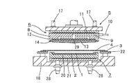
図1は第1の実施形態に係るウエハのマウント装置5の縦断正面図であり、その上部にはダイシングテープ4をウエハに押圧する上部枠体6が、下部にはウエハ1の凹凸形状に形成されたダイシングテープの貼り付け面を上面にして保持する下部枠体7が、その下部枠体7の外周外側全域には、ダイシングテープ4が貼り付けられたダイシングフレーム3を保持するフレーム台22が設けられている。
FIG. 1 is a longitudinal front view of a
前記上部枠体6は、図示しない機台上に水平に設けた支持枠15の下方にこの支持枠15と平行に設けられている。前記支持枠15上には下方に向けてその軸が伸出可能となるように昇降シリンダ16が設けられると共にこの昇降シリンダ16に沿った両側にガイド17、17が設けられている。前記昇降シリンダ16の軸の下端には上部枠体6が固定され、この上部枠体6は昇降シリンダ16の作用により、上端位置からダイシングテープ4を押し下げるまでの位置への昇降が自在になっている。前記上部枠体6は、円形状でその内周部分が凹状に形成された保持枠8と、弾性変形可能な部材からなる円形状の通気性部材13と、前記通気性部材13を接着等により固定支持する支持板12とから構成され、前記支持板12に固定支持された通気性部材13が保持枠8の凹状部に接着等により内嵌固定されている。
The
また、前記保持枠8には、図2及び図3のように、内部に通気孔9が前記凹状部分に向けて十字状に穿設され、通気性部材13を支持する支持板12の5箇所に設けられた開孔29を介して通気性部材13に連通するように形成されている。また、前記保持枠8の側面には通気孔9に圧縮空気を導入する通気パイプ10が設けられ、その一端には図示しないバルブと圧縮空気を送出するポンプが接続されている。また、前記保持枠8には、圧縮空気及び通気性部材13を加熱するヒータ11が前記通気性部材13とほぼ同径に埋設されている。また、前記保持枠8に装着された通気性部材13の外周にはゴムリング等のシール14が設けられている。
Further, as shown in FIG. 2 and FIG. 3, the holding
上記通気性部材13は、発泡ポリウレタン等の柔軟な弾性部材をウエハ1の凹凸形状に沿って弾性変形させる面から好ましく用いることができ、且つ通気性を有するように各セルが連通したものを好ましく用いることができる。
The
また、上記通気性部材13の大きさは、ウエハ1の凹凸形状をした貼り付け面を覆うことができるものを好ましく使用でき、通気性部材13の形状は、ダイシングテープ4を押圧する表面が平坦なものや中央が凸になるようにアールが付いたもの、また円錐形上の中央部が突出したもの等、ウエハ1の凹凸形状面に沿って弾性変形するものであれば特に制限無く使用できる。なお、この弾性変形も完全にウエハ1の凹凸形状面に沿って弾性変形するものでなくともある程度凹凸形状面に沿って弾性変形するものであれば、その後の通気性部材13を通じた圧縮空気の導入でダイシングテープ4が押圧されて凹凸面の形状に倣って変形するので問題なく使用できる。また、中央が凸になるようにアールが付いたものや円錐形状の中央部が突出したものを使用すれば、ダイシングテープ4をウエハ1に押圧する際に中央部から外周に向かって順次押圧することができるので気泡の発生やしわを防止する面で好ましい。
Further, the size of the air-
次に下部枠体7について図1に基づいて説明する。
Next, the
下部枠体7は、上面にウエハ1を載置して保持するように円形で凹状のテーブル面20が形成され、下部枠体7の内部にはテーブル面20とほぼ同径にヒータ21が埋設されている。前記下部枠体7は、図示しない機台上に設けられた支持枠18上に設けられ、下部枠体7の下方は支持枠18に対して昇降可能にガイド28が接続されている。
The
前記ガイド28は支持板27上に固定され、この支持板27にはナット部材26がボールネジ25と螺合するように設けられている。前記ボールネジ25は、支持枠18の下方に設けられた固定枠23に固定されたモータ24の軸と接続されており、このモータ24を駆動することで下部枠体7は支持板27を通じて支持枠18に対して昇降自在になっている。また下部枠体7は、ダイシングテープ4を押し下げた下降端に位置する上部枠体6に向けて上昇し、ダイシングテープ4を挟持して上部枠体6と密着するようになっている。
The
また、支持枠18上には、前記下部枠体7の外周外側全域に下部枠体7を取り囲むようにフレーム台22が設けられており、ダイシングフレーム3を吸着または適宜な固定手段で固定するようになっている。ダイシングテープ4が貼り付けられたダイシングフレーム3は、そのダイシングテープ4の粘着面が下方となるように固定される。
Further, a
以上が本発明の第1の実施形態の構成であり、次に第1の実施形態のウエハのマウント動作について図4乃至図9並びに図18に基づいて説明する。 The above is the configuration of the first embodiment of the present invention. Next, the wafer mounting operation of the first embodiment will be described with reference to FIGS. 4 to 9 and FIG.
図4のように上部枠体6は上昇位置に位置し、下部枠体7は下降位置に位置しており、この状態で下部枠体7のテーブル面20上に図示しない適宜の搬送手段で凹凸形状面を上にしたウエハ1を搬送する。
As shown in FIG. 4, the
次にダイシングテープ4が貼り付けられたダイシングフレーム3を図示しない適宜な搬送手段によりダイシングテープ4の粘着面がウエハ1の貼り付け面と対向するようにフレーム台22上に搬送する。なお、ウエハ1及びダイシングフレーム3は、予め適宜な位置決め手段で位置決めしておけば良い。
Next, the
図5のように搬送されたウエハ1を下部枠体7のテーブル面20上にその上面がテーブル面20の外周上面とほぼ一致するように載置保持し、ヒータ21でウエハ1を加熱する。上記ウエハ1の保持は適宜吸着等で固定するようにしても良い。なお、ヒータ21での加熱はダイシングテープ4の特性に応じて加熱温度を調節でき、加熱しないこともできる。また、ダイシングテープ4が貼り付けられたダイシングフレーム3はダイシングテープ4の粘着面とウエハ1が接しない程度の間隔を開けてフレーム台22に吸着や固定爪等の適宜手段で載置固定される。
The
図6及び図18(a)のようにヒータ11で加熱された上部枠体6を昇降シリンダ16の作用で下降させ、上部枠体6の下面に取り付けられた通気性部材13をダイシングテープ4の非粘着面側から押圧し、ダイシングテープ4を押し下げる。
このダイシングテープ4の押し下げによって、加熱や貼り付け時の張力等によって発生するダイシングテープ4の弛みやしわが伸ばされ、ダイシングテープ4が張った状態となる。このことにより、ダイシングテープ4がウエハ1と接触する際にしわや気泡が発生しない。なお、上記ヒータ11での加熱はダイシングテープ4の特性に合わせ適宜加熱温度を調節したり、ヒータ11を使用せずに行っても良い。
As shown in FIGS. 6 and 18A, the
When the dicing
次に図7、図18(b)のように下部枠体7をモータ24の駆動で上昇させてウエハ1の凹凸形状面をダイシングテープ4に押圧することで通気性部材13をウエハ1の凹凸形状に沿って弾性変形させるとともに上部枠体6のシール14と下部枠体7の外周上面とでダイシングテープ4を挟持することで上部枠体6と下部枠体7とを密着させてその内部を密閉状態に保持せしめる。なお、通気性部材13の弾性変形は、図18(b)のようにウエハ1の凹凸形状に完全に沿ったものでなくとも、ダイシングテープ4をウエハ1に押圧でき、ある程度ウエハ1の凹凸形状に沿って変形すれば良い。
Next, as shown in FIG. 7 and FIG. 18B, the
図7及び図18(c)のように前記通気性部材13をウエハ1の凹凸形状に沿って弾性変形させた状態で、圧縮空気(例えば0.1〜0.5MPaの加圧力)を通気性パイプ10を通じて上部枠体7の通気孔9に導入し、圧縮空気を支持板12の開孔29から通気性部材13に送出して通気性部材13の全域からダイシングテープ4に向けて圧縮空気を噴射させる。これによって通気性部材13を通じて噴射される圧縮空気の加圧力がダイシングテープ4の剛性に打ち勝ってダイシングテープ4をウエハ1の凹凸形状に沿ってさらに押込み、ウエハ1の凹凸形状に沿ってダイシングテープ4が密着する。この圧縮空気を導入して加圧する時間は30秒から90秒程度が好ましく、密着度合と量産性の面から60秒程度がより好ましい(この時間はダイシングテープ4の材質やウエハ1の凹凸形状、量産性を加味して上記に限定されずに適宜選択できる)。
7 and 18 (c), the air-
なお、上記はウエハ1の凹凸形状としてウエハ1の外周にリング状の外周リブ62を残し、その内周部分を研削したものを使用したが、図19(a)乃至(c)のようにウエハ1の裏面にバンプ38が設けられた凹凸形状を有するウエハやMEMS(マイクロエレクトロメカニカルシステム)の基板など各種の凹凸形状を有する基板やウエハに適用できる。
In the above description, the concave / convex shape of the
また、上記はダイシングテープ4を上部枠体6で押し下げた後、下部枠体7を押し上げてマウントするようにしたが、ダイシングテープ4の押し下げと下部枠体7の押し上げは連続的な動作で行なっても良い。
In the above, the dicing
上記のバンプ38を有するウエハ1の場合も図19(a)のようにダイシングテープ4を通気性部材13で押圧して押し下げる。次に図19(b)のように下部枠体6を押し上げてダイシングテープ4を挟持しながら上部枠体6と下部枠体7とを密着させてその内部を密閉状態にせしめるとともに通気性部材13をウエハ1の凹凸形状に沿って弾性変形させる。
Also in the case of the
この状態で図19(c)のように圧縮空気を通気孔9を通じて導入することで通気性部材13からその全域に圧縮空気を噴射させ、ダイシングテープ4をウエハ1のバンプ38の形状に沿って押圧して密着させる。
In this state, as shown in FIG. 19C, compressed air is introduced through the
この後、図8のように圧縮空気の通気を停止し大気解放した後、上部枠体6を昇降シリンダ16の作用で上昇させて下部枠体7との密着を解除させる。
Thereafter, as shown in FIG. 8, after the compressed air is stopped from flowing and released to the atmosphere, the
図9のように図示しない適宜の搬送手段により、ウエハ1のマウントが完了したダイシングフレーム3を取り出し、次のダイシング工程に供する。
The
以上が本発明の第1のウエハのマウント装置の実施形態であり、次に第2のウエハのマウント装置の実施形態について図10乃至図17に基づいて説明する。なお、同一部材については、第1の実施形態の符号と同じものを使用している。 The first embodiment of the first wafer mounting apparatus according to the present invention has been described above. Next, the second embodiment of the wafer mounting apparatus will be described with reference to FIGS. In addition, about the same member, the same thing as the code | symbol of 1st Embodiment is used.
図10は、本発明の第2の実施形態に係るウエハのマウント装置の縦断正面図であり、上部枠体6と下部枠体7の構成は第1の実施形態と同様であるので説明を省略する。
FIG. 10 is a longitudinal front view of the wafer mounting apparatus according to the second embodiment of the present invention, and the configuration of the
上部枠体6を取り囲むように上チャンバ30aが設けられ、この上チャンバ30aは、支持板36に設けられた昇降シリンダ37に支持され、前記支持板36が図示しない機台上の支柱に固定されている。前記上チャンバ30aは、後述する下チャンバ30bと合わさるまでの昇降が可能になっている。
An
また、前記上チャンバ30aの上部には支持枠34が立設され、その支持枠34の上部に2連の昇降シリンダ35、35が設けられており、この昇降シリンダ35、35のシリンダ軸が中央部に開口を持つドーナツ状の支持板33に固定されることで支持板33は昇降可能になっている。
Further, a
また、前記上チャンバ30aにはガイド32が取り付けられ、このガイド32の軸の下端が上部枠体6と接続されており、このガイド32の軸の上端が前記支持板33に固定されることで、上部枠体6は昇降シリンダ35、35の作用により支持板33とともに上チャンバ30aに対して昇降するようになっている。
In addition, a
また、上チャンバ30aには真空アダプタ31が設けられて図示しない適宜の真空ポンプと接続されている。前記上チャンバ30aは、下チャンバ30bと合わさって真空室を形成するようになっており、前記真空室を形成した際にその内部を前記真空アダプタ31を通じて減圧雰囲気にすることが可能になっている。また、上チャンバ30aには外部から圧縮空気を上部枠体6に導入する通気パイプ10が設けられている。
The
前記下チャンバ30bは、上チャンバ30bと対向するように設けられ、その内部に下部枠体7が下チャンバ30bに対して第1の実施形態同様に昇降動可能に設けられている。また、下部枠体7の外周外側全域に下部枠体7を取り囲むようにフレーム台22が固定して設けられている。
The
以上が、第2の実施形態に係るウエハのマウント装置の実施形態であり、第1の実施形態のウエハのマウント装置を上チャンバ30aと下チャンバ30bの内部に収めた構成となっている。
The above is the embodiment of the wafer mounting apparatus according to the second embodiment, and the wafer mounting apparatus of the first embodiment is housed in the
次に第2の実施形態に係るウエハのマウント装置のマウント動作について図11乃至図17に基づいて説明する。 Next, the mounting operation of the wafer mounting apparatus according to the second embodiment will be described with reference to FIGS.
図11のように上チャンバ30aが開放した状態で下部枠体7のテーブル面20上に位置決めされたウエハ1を図示しない適宜な搬送手段で搬送し、テーブル面20上にウエハ1を載置保持する。また、ダイシングテープ4の貼り付けられたダイシングフレーム3を図示しない適宜な手段でフレーム台22上に搬送し、ダイシングテープ4の粘着面とウエハ1の凹凸形状面が対向するようにするとともにウエハ1とダイシングテープ4が接着しない程度の間隔を開けてダイシングフレーム3をフレーム台22に適宜手段で固定する。
As shown in FIG. 11, the
図12のように上チャンバ30aを昇降シリンダ37の作用で下降させ、下チャンバ30bと密着させて真空室を形成するとともに、図示しない真空ポンプの作用で真空アダプタ31から排気し、真空室内を減圧雰囲気(例えば100〜1000Pa)にするとともにヒータ21でウエハ1を加熱する。このヒータ21での加熱はダイシングテープ4の材質に応じて適宜加熱温度を調節でき、加熱せずに行うようにしても良い。
As shown in FIG. 12, the
次に図13及び図18(a)のように減圧雰囲気を保った状態で上部枠体6を昇降シリンダ35、35の作用で下降させ、適宜、ヒータ11で加熱しながら通気性部材13でダイシングテープ4を押圧して押し下げる。
Next, as shown in FIG. 13 and FIG. 18A, the
図14、図18(b)及び(c)のように下部枠体7をモータ24の駆動で上昇させてウエハ1をダイシングテープ4に押圧して通気性部材13をウエハ1の凹凸形状面に沿って弾性変形させるとともに通気性パイプ10から圧縮空気(例えば0.1〜0.5MPaの加圧力)を導入して、通気孔9及び支持板12の開孔29を通じて通気性部材13の全域からダイシングテープ4に向けて圧縮空気を噴射させる。この圧縮空気を導入して加圧する時間は第1の実施形態と同様にすれば良い。
As shown in FIGS. 14, 18 (b) and 18 (c), the
これによって通気性部材13の弾性力がその後の加圧空気の噴射によりダイシングテープ4の剛性に打ち勝ってダイシングテープ4をウエハ1の凹凸形状に沿ってさらに押込み、ウエハ1の凹凸形状とダイシングテープ4が密着する。また、減圧雰囲気下でダイシングテープ4とウエハ1を貼り合わせるようにしているので気泡の発生がない。
As a result, the elastic force of the air-
図15のように圧縮空気の通気を停止し大気開放した後、真空アダプタ31から大気を導入して減圧雰囲気を解除する。
As shown in FIG. 15, after the compressed air is stopped from flowing and released to the atmosphere, the reduced pressure atmosphere is released by introducing the atmosphere from the
続いて図16のように昇降シリンダ37の作用で上チャンバ30aを上昇させ、図17のように図示しない適宜の搬送機構でウエハ1がマウントされたダイシングフレーム4を次のダイシング工程に供する。
Subsequently, the
以上が、本発明の第2の実施形態に係るウエハのマウント装置の実施形態である。 The above is the embodiment of the wafer mounting apparatus according to the second embodiment of the present invention.
次に第3の実施形態に係るウエハのマウント装置について図20、図22及び図23に基づいて説明する。 Next, a wafer mounting apparatus according to a third embodiment will be described with reference to FIGS. 20, 22 and 23. FIG.
第3の実施形態は、従来のウエハのマウント装置を利用しながら、さらにウエハ1の凹凸形状面に沿って密着性良くウエハ1をマウントするものである。
In the third embodiment, the
従来のウエハのマウント装置は、例えば、背景技術で説明した図23のような装置が利用できる。 As a conventional wafer mounting apparatus, for example, the apparatus shown in FIG. 23 described in the background art can be used.
また、別のウエハのマウント装置について以下に説明する図22のような装置も利用できる。 Further, another apparatus for mounting a wafer as shown in FIG. 22 described below can be used.
図22(a)のように図示しない適宜な開閉機構で開閉自在な上チャンバ52aと下チャンバ52bが設けられ、この上部チャンバ52aにはモータ51で回転可能でウエハ1の外周リブと内周研削部分の境界の凹凸形状に沿って弾性変形する弾性ローラ58が設けられている。この弾性ローラ58は、適宜円周方向に複数配置すれば良い。
As shown in FIG. 22A, an
また、下部チャンバ52bの内部には円形の貼付テーブル55が設けられ、その上面でウエハ1を載置保持するようになっており、この貼付テーブル55は適宜の機構で昇降可能になっている。
Further, a circular sticking table 55 is provided inside the
また、ダイシングテープ4が貼り付けられたダイシングフレーム3を載置固定するフレーム台53が貼付テーブル55の外周外側全域に設けられ、シリンダ56により昇降可能になっている。
In addition, a
次に、上記のウエハのマウント装置の動作について説明すると、図22(a)のように貼付テーブル55にウエハ1を載置し、ダイシングテープ4が貼り付けられたダイシングフレーム3をフレーム台53に載置固定するとともに上チャンバ52aを閉じて下チャンバ52bとで真空室を形成し、その内部を真空アダプタ57を通じて減圧雰囲気にする。
Next, the operation of the wafer mounting apparatus will be described. As shown in FIG. 22A, the
図22(b)のように貼付テーブル55及びフレーム台53を上昇させて弾性ローラ58をウエハ1の外周リブと内周研削部とに跨るように押圧して弾性ローラ58を凹凸部分の形状に沿って弾性変形させる。この状態でモータ51を駆動させて弾性ローラ58を回転させ、ウエハ1の外周部分全体を押圧してダイシングテープ4を貼り付ける。
As shown in FIG. 22B, the sticking table 55 and the
この後、図示しないが減圧状態を解除し、真空アダプタ57から大気を導入してウエハ1の内周研削部も大気による押圧でダイシングテープ4を密着させる。このようにしてダイシングフレーム3にマウントされたウエハ1は、本発明の第3の実施形態に係るウエハのマウント装置に供される。
Thereafter, although not shown, the reduced pressure state is released, the atmosphere is introduced from the
図20は、本発明の第3の実施形態に係るウエハのマウント装置であり、図20(a)のように図示しない適宜の駆動手段で昇降可能な上チャンバ47aとこの上チャンバ47aと合わさって密着することにより密閉室を形成する下チャンバ47bとから構成されている。
FIG. 20 shows a wafer mounting apparatus according to the third embodiment of the present invention. As shown in FIG. 20A, the
前記上チャンバ47aは、通気パイプ50が設けられ、図示しない圧縮ポンプと接続されて圧縮空気の通気が可能になっている。
The
また、前記下チャンバ47bは、前記ウエハ1のマウントされたダイシングフレーム3を載置して保持するテーブル面48が形成されている。なお、理解が容易なように図示誇張してあるためテーブル面48のウエハ1の載置面が凹状に形成されているが、載置面に上記マウント済みダイシングフレーム3が平坦に載置できるように構成すれば良い。また、下チャンバ47bの上チャンバ47aと密着する部分にはシール49が設けられている。
The
次に本発明の第3の実施形態について説明する。 Next, a third embodiment of the present invention will be described.
図20(a)のように開放状態の下チャンバ47bのテーブル面48上に適宜の手段でマウントされたウエハ1のマウント済みダイシングフレーム3をそのダイシングテープ4が上面となるように載置する。
As shown in FIG. 20A, the mounted
図20(b)のように上チャンバ47aを閉じて密閉室を形成する。
As shown in FIG. 20B, the
図20(c)のように前記密閉室内に通気パイプ50を通じて圧縮空気(例えば0.1〜0.5MPa)を導入し、その圧縮空気をダイシングテープ4に向けて噴射させてダイシングテープ4をウエハ1の凹凸形状に沿って押圧する。このようにすることで、従来のマウント装置を有効利用し、且つ、従来のマウント装置で不十分であったダイシングテープ4の貼り付けをさらに精度良くウエハ1の凹凸形状に沿って密着させて貼り付けることが可能となる。また、適宜ウエハ1や圧縮空気を加熱するようにしても良い。
As shown in FIG. 20 (c), compressed air (for example, 0.1 to 0.5 MPa) is introduced into the sealed chamber through the
以上が本発明の第3の実施形態であり、次に第4の実施形態に係るウエハのマウント装置70について図21に基づいて説明する。 The above is the third embodiment of the present invention. Next, a wafer mounting apparatus 70 according to the fourth embodiment will be described with reference to FIG.
上記第3の実施形態のように図23のような従来のウエハのマウント装置70でダイシングテープ4をウエハ1に貼り付けてマウントした後、第1の実施形態のウエハのマウント装置を適用してダイシングテープ4をウエハ1の凹凸形状に沿って押圧して貼り付けるものであり、共通部分には同一の符号を付して説明は省略する。
After the
図21(a)のように上部枠体6を上昇位置に位置させるとともに、下部枠体7を上昇位置に位置させて、ウエハ1がマウントされたダイシングフレーム3をフレーム台22に載置固定した際に、ダイシングフレーム3の上面と、下部枠体7の外周上面とがほぼ面一になるようにしておく。この状態で、ウエハ1がマウントされたダイシングフレーム3をフレーム台22に載置固定するとともにウエハ1を下部枠体7のテーブル面20上に載置保持する。
As shown in FIG. 21A, the
図21(b)のように上部枠体6を昇降シリンダ16の作用で下降させ、通気性部材13でダイシングテープ4をウエハ1に押圧して、通気性部材13をウエハ1の凹凸形状に沿って弾性変形させるとともに上部枠体6と下部枠体7とをダイシングテープ4を挟持しながら密着させ、密閉状態を形成する。この時、適宜ヒータ11及びヒータ21で加熱を行っても良い。
As shown in FIG. 21B, the
図21(c)のように上部枠体6と下部枠体7とで密閉状態を保持せしめながら、通気性パイプ10を通じて上部枠体6に圧縮空気を導入し、通気性部材13の全域に圧縮空気を噴射せしめて、ダイシングテープ4をウエハ1の凹凸形状に沿って押圧する。
As shown in FIG. 21 (c), compressed air is introduced into the
以上が本発明の実施形態であるが、適宜発明の範囲内で変更することができる。例えば、本発明の第1及び第2の実施形態では上部枠体6及び下部枠体7を昇降可能に設けたが、上部枠体6を固定しておき、フレーム台22と下部枠体7とを昇降可能に構成しても良く、相対的な動作で同一の作用効果が得られれば適用可能である。また、各実施形態においてウエハ1に保護テープ2が貼り付けられたものを用いたが、保護テープ2が貼り付けられていないウエハ1にも同様に適用でき、この場合は、ウエハ1を載置するテーブル面に保護シートを敷設するなどすれば良い。
The above is the embodiment of the present invention, but can be appropriately changed within the scope of the invention. For example, in the first and second embodiments of the present invention, the
また、第4の実施形態において定型のマウントウエハを使用する場合は、下部枠体7を適宜位置で固定しておいても良い。
Moreover, when using a fixed mount wafer in the fourth embodiment, the
また、上部枠体6のヒータ11による加熱や下部枠体7のヒータ21による加熱は、適用するダイシングテープ4の特性に応じて加熱温度を変更したり、ヒータ11、ヒータ21を使用せずに貼り付けたりすることも可能である。
The heating of the
また、前記の各実施形態においては、円形状のウエハを前提に記載したが、通気性部材13の形状等を変更すれば矩形状の各種基板等に利用することができる。また、通気性部材13の厚みも各種基板の凹凸の深さに合わせて適宜に選択すれば良い。
In each of the embodiments described above, a circular wafer has been described. However, if the shape of the air-
なお、マウント後のウエハ1から保護テープ2の剥離を行なう際は、ウエハ1の内周研削部分がダイシングテープ4を介して凹面となっているので、内周研削面の部分を凸状になったテーブルで保持したり、内外周が独立して制御できるテーブルで外周リブと内周研削面を保持したりあるいはエアの圧力で内周研削面部分を保持するなど、適宜な手段で保持して行なえば良い。
When the
1 ウエハ
2 保護テープ
3 ダイシングフレーム
4 ダイシングテープ
5 マウント装置
6 上部枠体
7 下部枠体
8 保持枠
9 通気孔
10 通気パイプ
11 ヒータ
12 支持板
13 通気性部材
14 シール
15 支持枠
16 昇降シリンダ
17 ガイド
18 支持枠
20 テーブル面
21 ヒータ
22 フレーム台
23 固定枠
24 モータ
25 ボールネジ
26 ナット部材
27 支持板
28 ガイド
29 開孔
30a 上チャンバ
30b 下チャンバ
31 真空アダプタ
32 ガイド
33 支持板
34 支持枠
35 昇降シリンダ
36 支持板
37 昇降シリンダ
38 バンプ
39 マウント装置
46 マウント装置
47a 上チャンバ
47b 下チャンバ
48 テーブル面
49 シール
50 通気パイプ
51 モータ
52a 上チャンバ
52b 下チャンバ
53 フレーム台
54 ヒータ
55 貼付テーブル
56 シリンダ
57 真空アダプタ
58 弾性ローラ
60 金属膜
61 仕上研磨面
62 外周リブ
63 粗削り面
71 貼付テーブル
72 フレーム台
73 揺動軸
74 貼付ローラ
75 バネ
76 機台
DESCRIPTION OF
Claims (4)
互いに昇降可能に支持された上下一対の上部枠体と下部枠体とからなり、これら上部枠体と下部枠体の密着により、その内部を密閉状態になるように構成するとともに、
前記上部枠体には、その下面に弾性変形可能な材質からなる通気性部材を装着して、この上部枠体に穿設された通気孔を通して前記通気性部材全域に圧縮空気を導入するように構成し、
前記下部枠体には、その上面にウエハを載置保持するようにテーブル面を形成し、前記下部枠体の外周外側全域にはダイシングテープが貼り付けられたダイシングフレームを保持するフレーム台が設けられており、
前記上部枠体の下降動で前記通気性部材を介してダイシングテープを押し下げ、然る後、下部枠体の上昇動により、通気性部材を弾性変形させながら該下部枠体のテーブル面に保持されたウエハの凹凸形状に沿ってダイシングテープを押圧するとともに、これら上下枠体の密着により、その内部を密閉状態に保持せしめた後、上部枠体の通気孔から圧縮空気を導入し、この導入された圧縮空気を通気性部材の全域から噴射せしめることにより、ダイシングテープをウエハの凹凸面の形状に沿って貼り付けるようにしたことを特徴とするウエハのマウント装置。 In a wafer mounting apparatus that mounts a wafer having one surface with an uneven shape on a dicing frame via a dicing tape,
Consists of a pair of upper and lower upper and lower frames supported so as to be able to move up and down.
A breathable member made of an elastically deformable material is attached to the lower surface of the upper frame body, and compressed air is introduced to the entire area of the breathable member through a vent hole formed in the upper frame body. Configure
A table surface is formed on the upper surface of the lower frame so as to place and hold a wafer, and a frame base for holding a dicing frame with a dicing tape attached is provided on the entire outer periphery of the lower frame. And
The dicing tape is pushed down through the air-permeable member by the lowering movement of the upper frame, and then held by the table surface of the lower frame while the air-permeable member is elastically deformed by the upward movement of the lower frame. The dicing tape is pressed along the concave and convex shape of the wafer, and the inside of the upper and lower frames is held in a sealed state by the close contact between the upper and lower frames, and then compressed air is introduced from the vents of the upper frame. A wafer mounting apparatus, wherein the compressed air is sprayed from the entire area of the air-permeable member so that the dicing tape is attached along the shape of the uneven surface of the wafer.
互いに昇降可能に支持された上下一対の上部枠体と下部枠体とからなり、これら上部枠体と下部枠体の密着により、その内部を密閉状態になるように構成するとともに、
前記上部枠体には、その下面に弾性変形可能な材質からなる通気性部材を装着して、この上部枠体に穿設された通気孔を通して前記通気性部材全域に圧縮空気を導入するように構成し、
前記下部枠体の上面には、ウエハがマウントされたダイシングフレームを前記ウエハが下面となるように載置保持するようにテーブル面を形成し、前記下部枠体の外周外側全域にはウエハがマウントされたダイシングフレームのダイシングフレーム部分を保持するフレーム台が設けられており、
ウエハがマウントされたダイシングフレームのウエハ部分を前記下部枠体のテーブル面に保持するとともにダイシングフレーム部分をフレーム台に保持し、この後、前記上部枠体の下降動で前記通気性部材を介してダイシングテープを押圧することで通気性部材を弾性変形させながら該下部枠体のテーブル面に保持されたウエハの凹凸形状に沿ってダイシングテープを押圧するとともに、これら上下枠体の密着により、その内部を密閉状態に保持せしめた後、上部枠体の通気孔から圧縮空気を導入し、この導入された圧縮空気を通気性部材の全域から噴射せしめることにより、ダイシングテープをウエハの凹凸面の形状に沿って貼り付けるようにしたことを特徴とするウエハのマウント装置。 A wafer mounting apparatus for mounting a wafer having one surface with an uneven shape on a dicing frame via a dicing tape, and then pressing the dicing tape against the wafer again.
Consists of a pair of upper and lower upper and lower frames supported so as to be able to move up and down.
A breathable member made of an elastically deformable material is attached to the lower surface of the upper frame body, and compressed air is introduced to the entire area of the breathable member through a vent hole formed in the upper frame body. Configure
A table surface is formed on the upper surface of the lower frame so that a dicing frame on which the wafer is mounted is placed and held so that the wafer is on the lower surface, and the wafer is mounted on the entire outer periphery of the lower frame. A frame base for holding a dicing frame portion of the dicing frame is provided,
The wafer portion of the dicing frame on which the wafer is mounted is held on the table surface of the lower frame body, and the dicing frame portion is held on the frame base. Thereafter, the upper frame body is moved downward through the air-permeable member. While pressing the dicing tape, the air-permeable member is elastically deformed while pressing the dicing tape along the uneven shape of the wafer held on the table surface of the lower frame, Is held in a hermetically sealed state, and then compressed air is introduced from the ventilation holes of the upper frame, and the introduced compressed air is sprayed from the entire area of the air-permeable member, so that the dicing tape is formed into the shape of the uneven surface of the wafer. A wafer mounting device characterized in that the wafer mounting device is attached along.
Priority Applications (1)
| Application Number | Priority Date | Filing Date | Title |
|---|---|---|---|
| JP2008291870A JP5317267B2 (en) | 2008-11-14 | 2008-11-14 | Wafer mounting device |
Applications Claiming Priority (1)
| Application Number | Priority Date | Filing Date | Title |
|---|---|---|---|
| JP2008291870A JP5317267B2 (en) | 2008-11-14 | 2008-11-14 | Wafer mounting device |
Publications (3)
| Publication Number | Publication Date |
|---|---|
| JP2010118584A JP2010118584A (en) | 2010-05-27 |
| JP2010118584A5 JP2010118584A5 (en) | 2012-01-05 |
| JP5317267B2 true JP5317267B2 (en) | 2013-10-16 |
Family
ID=42306047
Family Applications (1)
| Application Number | Title | Priority Date | Filing Date |
|---|---|---|---|
| JP2008291870A Expired - Fee Related JP5317267B2 (en) | 2008-11-14 | 2008-11-14 | Wafer mounting device |
Country Status (1)
| Country | Link |
|---|---|
| JP (1) | JP5317267B2 (en) |
Families Citing this family (28)
| Publication number | Priority date | Publication date | Assignee | Title |
|---|---|---|---|---|
| JP5261308B2 (en) * | 2009-07-24 | 2013-08-14 | リンテック株式会社 | Pressing device |
| JP5543812B2 (en) * | 2010-03-23 | 2014-07-09 | 日東電工株式会社 | Adhesive tape application method and adhesive tape application device |
| CN101916739B (en) * | 2010-07-13 | 2012-08-01 | 上海技美电子科技有限公司 | Wafer carrying device |
| JP5660821B2 (en) * | 2010-08-06 | 2015-01-28 | リンテック株式会社 | Sheet sticking device and sticking method |
| JP5542582B2 (en) * | 2010-08-26 | 2014-07-09 | リンテック株式会社 | Sheet sticking device and sticking method |
| JP5542583B2 (en) * | 2010-08-26 | 2014-07-09 | リンテック株式会社 | Sheet sticking device and sticking method |
| JP5643579B2 (en) * | 2010-09-03 | 2014-12-17 | リンテック株式会社 | Sheet sticking device and sticking method |
| JP5626782B2 (en) * | 2010-09-13 | 2014-11-19 | リンテック株式会社 | Sheet pasting device |
| JP5691364B2 (en) * | 2010-10-06 | 2015-04-01 | 富士電機株式会社 | Tape sticking device and tape sticking method |
| JP5563423B2 (en) * | 2010-10-19 | 2014-07-30 | リンテック株式会社 | Sheet sticking device and sticking method |
| JP5953033B2 (en) * | 2011-11-21 | 2016-07-13 | リンテック株式会社 | Sheet sticking device and sticking method |
| JP5895676B2 (en) * | 2012-04-09 | 2016-03-30 | 三菱電機株式会社 | Manufacturing method of semiconductor device |
| JP2013232582A (en) * | 2012-05-01 | 2013-11-14 | Nitto Denko Corp | Method of applying adhesive tape and adhesive tape applying apparatus |
| JP6126938B2 (en) * | 2013-08-09 | 2017-05-10 | リンテック株式会社 | Sheet sticking device and sheet sticking method |
| JP6641209B2 (en) * | 2016-03-22 | 2020-02-05 | 株式会社ディスコ | Protective member forming device |
| JP6837717B2 (en) * | 2017-05-11 | 2021-03-03 | 株式会社ディスコ | Wafer processing method |
| JP6925714B2 (en) * | 2017-05-11 | 2021-08-25 | 株式会社ディスコ | Wafer processing method |
| SG11202010427SA (en) * | 2018-04-24 | 2020-11-27 | Disco Hi Tec Europe Gmbh | Device and method for attaching protective tape on semiconductor wafer |
| CN109659263B (en) * | 2019-01-10 | 2023-09-05 | 江苏汇成光电有限公司 | Wafer film laminating device |
| WO2020196794A1 (en) * | 2019-03-27 | 2020-10-01 | 三井化学東セロ株式会社 | Protection film, method for affixing same, and method for manufacturing semiconductor component |
| JP7246244B2 (en) * | 2019-05-09 | 2023-03-27 | 株式会社ディスコ | Method for attaching protective member to workpiece |
| JP7285133B2 (en) * | 2019-05-17 | 2023-06-01 | 日東電工株式会社 | Sheet material pasting method and sheet material pasting device |
| KR102258721B1 (en) * | 2019-08-28 | 2021-05-28 | 에스케이실트론 주식회사 | Wafer mounting device and operating method thereof |
| JP7417246B2 (en) * | 2019-10-31 | 2024-01-18 | 株式会社タカトリ | Pasting device and method |
| JP7521902B2 (en) * | 2020-02-14 | 2024-07-24 | 株式会社ディスコ | Tape application device |
| JP2023544933A (en) * | 2021-09-10 | 2023-10-26 | 中国華能集団清潔能源技術研究院有限公司 | In-situ flash evaporation deposition system for perovskite solar cells |
| CN115036253A (en) * | 2022-05-05 | 2022-09-09 | 武汉新芯集成电路制造有限公司 | Adsorption device and adsorption method |
| CN115241063A (en) * | 2022-07-04 | 2022-10-25 | 江苏东海半导体股份有限公司 | Preparation method of insulated gate bipolar transistor |
Family Cites Families (7)
| Publication number | Priority date | Publication date | Assignee | Title |
|---|---|---|---|---|
| JPS5938278B2 (en) * | 1976-09-24 | 1984-09-14 | 株式会社日立製作所 | How to attach items |
| JPS5578545A (en) * | 1978-12-11 | 1980-06-13 | Fujitsu Ltd | Manufacture of semiconductor |
| JPH0254564A (en) * | 1988-08-18 | 1990-02-23 | Nec Corp | Device for application of adhesive tape to semiconductor wafer |
| JPH08172061A (en) * | 1994-10-20 | 1996-07-02 | Murata Mfg Co Ltd | Method of affixing sheet |
| JP4841355B2 (en) * | 2006-08-08 | 2011-12-21 | 日東電工株式会社 | Method for holding semiconductor wafer |
| JP2009141276A (en) * | 2007-12-10 | 2009-06-25 | Fuji Electric Device Technology Co Ltd | Semiconductor device and its manufacturing method |
| JP4773419B2 (en) * | 2007-12-20 | 2011-09-14 | リンテック株式会社 | Sheet sticking device and sticking method |
-
2008
- 2008-11-14 JP JP2008291870A patent/JP5317267B2/en not_active Expired - Fee Related
Also Published As
| Publication number | Publication date |
|---|---|
| JP2010118584A (en) | 2010-05-27 |
Similar Documents
| Publication | Publication Date | Title |
|---|---|---|
| JP5317267B2 (en) | Wafer mounting device | |
| JP2010118584A5 (en) | ||
| JP4022306B2 (en) | Wafer bonding method and bonding apparatus | |
| KR101280670B1 (en) | Method for joining adhesive tape to semiconductor wafer, method for separating protective tape from semiconductor wafer, and apparatuses using the methods | |
| KR102445608B1 (en) | Wafer processing method | |
| JP2008103493A (en) | Method and apparatus for picking up chip | |
| JP2008066684A (en) | Device for mounting substrate to dicing frame | |
| JP2006100763A (en) | Manufacturing method and joining apparatus of solid-state imaging device | |
| JP6029354B2 (en) | Wafer grinding apparatus and wafer grinding method | |
| KR101747485B1 (en) | Sheet attaching device and attaching method | |
| JP5337620B2 (en) | Workpiece adhesive holding device and vacuum bonding machine | |
| JP5451335B2 (en) | Mounting apparatus and mounting method | |
| WO2009081880A1 (en) | Sticking method and sticking device of sticking material | |
| JP3816297B2 (en) | Polishing equipment | |
| JP2009170761A (en) | Pasting apparatus of substrate body, and treating method of substrate body | |
| KR101583816B1 (en) | Chemical mechanical polishing apparatus which prevents wafer dechuck error and control method thereof | |
| KR102445610B1 (en) | Wafer processing method | |
| JP5551418B2 (en) | Sheet sticking device and sheet sticking method | |
| JP7271619B2 (en) | CMP apparatus and method | |
| JP4051125B2 (en) | Wafer bonding equipment | |
| JP6472666B2 (en) | Holding method for plate workpiece | |
| JP5475481B2 (en) | Sheet sticking device and sheet sticking method | |
| JP2013222749A (en) | Wafer suction device and wafer suction method | |
| JP2011155099A (en) | Apparatus and method for sticking sheet | |
| JPH07226350A (en) | Wafer pasting device and its method |
Legal Events
| Date | Code | Title | Description |
|---|---|---|---|
| A521 | Request for written amendment filed |
Free format text: JAPANESE INTERMEDIATE CODE: A523 Effective date: 20111031 |
|
| A621 | Written request for application examination |
Free format text: JAPANESE INTERMEDIATE CODE: A621 Effective date: 20111031 |
|
| A977 | Report on retrieval |
Free format text: JAPANESE INTERMEDIATE CODE: A971007 Effective date: 20130220 |
|
| A131 | Notification of reasons for refusal |
Free format text: JAPANESE INTERMEDIATE CODE: A131 Effective date: 20130326 |
|
| A521 | Request for written amendment filed |
Free format text: JAPANESE INTERMEDIATE CODE: A523 Effective date: 20130426 |
|
| TRDD | Decision of grant or rejection written | ||
| A01 | Written decision to grant a patent or to grant a registration (utility model) |
Free format text: JAPANESE INTERMEDIATE CODE: A01 Effective date: 20130628 |
|
| A61 | First payment of annual fees (during grant procedure) |
Free format text: JAPANESE INTERMEDIATE CODE: A61 Effective date: 20130705 |
|
| R150 | Certificate of patent or registration of utility model |
Ref document number: 5317267 Country of ref document: JP Free format text: JAPANESE INTERMEDIATE CODE: R150 Free format text: JAPANESE INTERMEDIATE CODE: R150 |
|
| R250 | Receipt of annual fees |
Free format text: JAPANESE INTERMEDIATE CODE: R250 |
|
| R250 | Receipt of annual fees |
Free format text: JAPANESE INTERMEDIATE CODE: R250 |
|
| LAPS | Cancellation because of no payment of annual fees |